audio video surround receiver vr-7080 krf …manual.kenwood.com/files/b60-5341-00.pdfb60-5341-00 00...
TRANSCRIPT

B60-5341-00 00 MA (K, P, Y) 0209
AUDIO VIDEO SURROUND RECEIVER
VR-7080KRF-X9070DINSTRUCTION MANUALKENWOOD CORPORATION
About the supplied remote controlCompared to standard remote controls, the remote control supplied with this receiver has severaloperation modes. These modes enable the remote control to control other audio/video components. Inorder to effectively use the remote control, it is important to read the operating instructions and obtaina proper understanding of the remote control and how to switch its operation modes (etc.).Using the remote control without completely understanding its design and how to switch the operationmodes may result in incorrect operations.
This instruction manual is for some models. Model availability and features (functions) may differdepending on the country and sales area.
*5341/01-09/EN 2003/03/19, 4:12 PM1

2 EN
Units are designed for operation as follows.
U.S.A. and Canada ........................................... AC 120 V only
Australia ........................................................... AC 240 V only
Europe and U.K ................................................ AC 230 V only
China and Russia ............................................. AC 220 V only
Other countries .......... AC 110-120 / 220-240 V switchable*
Before applying the power Caution : Read this page carefully to ensure safeoperation.
CAUTIONRISK OF ELECTRIC SHOCK
DO NOT OPEN
Safety precautions
WARNING :TO PREVENT FIRE OR ELECTRIC SHOCK,DO NOT EXPOSE THIS APPLIANCE TORAIN OR MOISTURE.
CAUTION: TO REDUCE THE RISK OF ELECTRIC SHOCK, DO NOTREMOVE COVER (OR BACK). NO USER-SERVICEABLE PARTSINSIDE. REFER SERVICING TO QUALIFIED SERVICE PERSONNEL.
THE LIGHTNING FLASH WITH ARROWHEAD SYMBOL,WITHIN AN EQUILATERAL TRIANGLE, IS INTENDED TOALERT THE USER TO THE PRESENCE OF UNINSULATED“DANGEROUS VOLTAGE” WITHIN THE PRODUCT’SENCLOSURE THAT MAY BE OF SUFFICIENT MAGNITUDETO CONSTITUTE A RISK OF ELECTRIC SHOCK TO PERSONS.
THE EXCLAMATION POINT WITHIN AN EQUILATERALTRIANGLE IS INTENDED TO ALERT THE USER TO THEPRESENCE OF IMPORTANT OPERATING ANDMAINTENANCE (SERVICING) INSTRUCTIONS IN THELITERATURE ACCOMPANYING THE APPLIANCE.
How to use this manual
This manual is divided into four sections, Preparations, Operations,Remote Control, and Additional Information.
PreparationsShows you how to connect your audio and video components to thereceiver and prepare the surround processor.Since this receiver works with all your audio and video components, wewill guide you in setting up your system to be as easy as possible.
OperationsShows you how to operate the various functions available on thereceiver.
Remote ControlShows you how to operate other components using the remote control,as well as a detailed explanation of all remote control operations. Onceyou have registered your components with the proper setup codes, you’llbe able to operate both this receiver and your other AV components (TV,VCR, DVD player, CD player, etc.) using the remote control supplied withthis receiver.
Additional InformationShows you additional information such as “In case of difficulty”(troubleshooting) and “Specifications”.
* AC voltage selectionThe AC voltage selector switch on the rear panel is set to the voltagethat prevails in the area to which the unit is shipped. Beforeconnecting the power cord to your AC outlet, make sure that thesetting position of this switch matches your line voltage. If not, itmust be set to your voltage in accordance with the following direction.
VOLTAGE SELECTORAC 110-120V~
AC 220-240V~
Note:
Our warranty does not cover damage caused by excessive linevoltage due to improper setting of the AC voltage selector switch.
AC voltage selector switch
Move switch lever to matchyour line voltage with a smallscrewdriver or other pointedtool.
*5341/01-09/EN 2003/03/19, 4:12 PM2

3 EN
Basic remote control operations for othercomponents ....................................................... 40
Registering setup codes for othercomponents ..................................................... 40Searching for your codes ................................. 40Checking the codes ......................................... 41Re-assigning device keys ................................ 41Operating other components .......................... 41Storing the remote control code of the othercomponents ..................................................... 42Setup code chart .............................................. 43CASSETTE deck, CD player & MD recorderoperations ........................................................ 47Other components’ operations ....................... 48
In case of difficulty .......................................... 50Specifications .................................................. 52
ContentsCaution : Read the pages marked carefully to ensure
safe operation.
Before applying the power
Before applying the power .............................. 2Safety precautions ............................................. 2How to use this manual ..................................... 2Unpacking .......................................................... 4Preparing the remote control ............................ 4Special features ................................................. 6
Names and functions of parts ......................... 7Main unit ............................................................ 7Remote control unit ............................................... 8
Setting up the system ...................................... 10Connecting the terminals ................................ 11Connecting audio components ........................ 12Connecting video components ........................ 13Digital connections .......................................... 14Connecting video components(COMPONENT VIDEO) .................................... 15Connecting a DVD player (6-channel input) ..... 16Connecting the speakers ................................. 17PRE OUT connections ..................................... 18Connecting to another room (ROOM B) ......... 19Connecting the external IR Repeater .............. 20Connecting to the AV AUX jacks ..................... 21Connecting the antennas ................................. 21Connecting the system control ....................... 22
Preparing for surround sound ....................... 23Speaker settings .............................................. 23
Normal playback.............................................. 26Preparing for playback ..................................... 26Listening to a source component .................... 26Adjusting the sound ......................................... 27
Recording .......................................................... 29Recording audio (analog sources) ................... 29Recording video ............................................... 29Recording audio (digital sources) .................... 29
Listening to radio broadcasts ....................... 30Tuning radio stations ....................................... 30Presetting radio stations manually .................. 30Receiving preset stations ................................ 31Receiving preset stations in order (P.CALL) ... 31
Ambience effects ............................................. 32Surround modes .............................................. 32Surround play ................................................... 35DVD 6-channel playback .................................. 36Convenient functions ....................................... 37
Preparations
Operations
Remote Control
AdditionalInformation
*5341/01-09/EN 2003/03/19, 4:12 PM3

4 EN
Remote control operationWhen the STANDBY indicator is lit, the power turns ON when you pressthe RCVR PWR (receiver power) key on the remote control. When thepower comes ON, press the key you want to operate.
PTY
RCVRPWR
6 m
• When pressing more than one remote control key successively, press thekeys securely by leaving an interval of 1 second or more between keys.
Notes1. The supplied batteries may have shorter lives than ordinary batteries
due to use during operation checks.2. When the remote-controllable distance gets shorter than before,
replace all batteries with new ones.3. Placing the remote sensor in direct sunlight, or in direct light from a
high frequency fluorescent lamp may cause malfunction.In such a case, change the location of the system installation toprevent malfunction.
Before applying the power
Loading the batteries1 Remove the cover. 2 Insert the batteries.
3 Close the cover.
• Insert four AAA-size (R03) batteries as indicated by the polaritymarkings.
Preparing the remote control
Operating range (Approx.) Remote sensor
Infrared ray system
Memory back up functionPlease note that the following items will be deleted from the unit'smemory if the power cord is disconnected from the AC outlet forapproximately 1 day.
• Power mode.• Input selector settings.• Picture output.• Speaker ON/OFF.• Volume level.• BASS, TREBLE, INPUT level.• TONE ON/OFF.• LOUDNESS ON/OFF.• Dimmer level.• MD/TAPE settings.• Listen mode setting.• Speaker settings.• SURR : MIX ON/OFF.• SW RE-MIX ON/OFF.• Distance setting.
• Bass peak level.• Display mode.• Input mode setting.• Midnight mode setting.• PRO LOGIC II mode setting.• CS II mode setting.• Broadcast band.• Frequency setting.• Preset stations.• Tuning mode.• THX mode.• DSP mode.• ACTIVE EQ mode.• SPEAKER EQ mode.
UnpackingUnpack the unit carefully and make sure that all accessories are
present.
FM indoor antenna (1) AM loop antenna (1)
Remote control unit (1) Batteries (R03/AAA) (4)RC-R2003
PTY
If any accessories are missing, or if the unit is damaged or fails to operate,notify your dealer immediately. If the unit was shipped to you directly,notify your shipper immediately. Kenwood recommends that you retainthe original carton and packing materials in case you need to move or shipthe unit in the future.Keep this manual handy for future reference.
1
2
1
2
*5341/01-09/EN 2003/03/19, 4:12 PM4

5 EN
Note to CATV system installerThis reminder is provided to call the CATV system installer's attentionto Article 820-40 of the NEC that provides guidelines for propergrounding and, in particular, specifies that the cable ground shall beconnected to the grounding system of the building, as close to thepoint of cable entry as practical.
For the U.S.A.
FCC WARNINGThis equipment may generate or use radio frequency energy. Changesor modifications to this equipment may cause harmful interferenceunless the modifications are expressly approved in the instructionmanual. The user could lose the authority to operate this equipmentif an unauthorized change or modification is made.
NOTE:This equipment has been tested and found to comply with the limits fora Class B digital device, pursuant to Part 15 of the FCC Rules. Theselimits are designed to provide reasonable protection against harmfulinterference in a residential installation. This equipment may causeharmful interference to radio communications, if it is not installed andused in accordance with the instructions. However, there is no guaranteethat interference will not occur in a particular installation. If thisequipment does cause harmful interference to radio or televisionreception, which can be determined by turning the equipment off andon, the user is encouraged to try to correct the interference by one ormore of the following measures:– – Reorient or relocate the receiving antenna.– – Increase the separation between the equipment and receiver.– – Connect the equipment into an outlet on a circuit different from
that to which the receiver is connected.– – Consult the dealer or an experienced radio / TV technician for help.
For the U.S.A. Channel space switching(Except for the U.S.A., Canada, U.K., and Australia)
The space between radio channels has been set to the one thatprevails in the area to which the system is shipped. However, if thecurrent channel space setting does not match the setting in the areawhere the system is to be used, for instance when you move fromarea 1 or area 2 shown in the following table or vice versa, properreception of AM/FM broadcasts cannot be expected. In this case,change the channel space setting in accordance with your area byreferring to the following table.
Area CHANNELSpace Frequency
1 U.S.A., Canada and South FM: 100 kHzAmerican countries AM: 10 kHz
2 Other countries FM: 50 kHzAM: 9 kHz
Turn the power OFF by pressing the POWER key before moving theswitch lever. Move switch lever to match your area with a smallscrewdriver or other pointed tool, then turn the power on again.
As an ENERGY STAR® Partner, KenwoodCorporation has determined that this productmeets the ENERGY STAR® guidelines forenergy efficiency.This product can saveenergy. Saving energy reduces air pollution
and lowers utility bills.
Maintenance of the unitWhen the front panel or case becomes dirty, wipe with a soft, drycloth. Do not use thinner, benzine, alcohol, etc. for these agents maycause discoloration.
In regard to contact cleanerDo not use contact cleaners because it could cause a malfunction. Bespecially careful not to use contact cleaners containing oil, for theymay deform the plastic component.
Before applying the power
50µs AM 9kHz FM50kHz
75µs AM 10kHz FM100kHz
DE-EMPHASISCHANNEL SPACE
DE-EMPHASISCHANNEL SPACE
50us AM 9kHz FM50kHz
75us AM 10kHz FM100kHz
*5341/01-09/EN 2003/03/19, 4:12 PM5

6 EN
Before applying the power
Special features
True home theater soundThis receiver incorporates a wide variety of surround modes to bring youmaximum enjoyment from your video software. Select a surround modeaccording to your equipment or the software you are going to play andenjoy! ¤
THXTHX mode activates proprietary THX features that help recreate thecinematic experience in a home environment. fl
THX Surround EXDuring THX Surround EX mode, film soundtracks that have beenencoded with Dolby Digital Surround EX technology are able to reproducean extra channel which has been added during the mixing of theprogram. This channel is called Surround Back.THX Surround EX mode activates proprietary THX features that helprecreate the cinematic experience in a home environment. fl
Dolby Digital and Dolby Digital EXThe DOLBY DIGITAL mode lets you enjoy full digital surround fromsoftware processed in the Dolby Digital format. Dolby Digital providesup to 5.1 channels of independent digital audio for better sound qualityand more powerful presence than conventional Dolby Surround.As for Dolby Digital EX, it creates six full-bandwidth output channelsfrom the 5.1 channel sources. This is done using a matrix decoder thatderives three surround channels from the two in the original recording.For best results, Dolby Digital EX should be used with movie soundtracksrecorded with Dolby Digital Surround EX.
Dolby PRO LOGIC IIDOLBY PRO LOGIC II, whilst totally compatible with its predecessorPRO LOGIC, provides greater advantages in surround sound. It allowsthe user to enjoy the conventional stereo or Dolby Surround with aconvincing “5.1 like” presentation. PRO LOGIC II offers special featuresfor controlling the overall spatial, dimensionality and frontal sound fieldimaging. PRO LOGIC II produces an impressive surround sound fromvideo software marked and three-dimensional spacefrom music CD. When listening to music, you will be able to enjoy theexperience of sheer STEREO surround sound.
DTS and DTS-ESDTS (Digital Theater System) is a 5.1 channel digital audio format thatprovides five full spectrum channels and one low-frequency (subwoofer)channel for unprecedented clarity, optimum channel separation and a(wide) dynamic range.DTS-ES (Extended Surround) presents 6.1 channels surround systemwith additional Surround Back channel which evolved from theconventional 5.1 channels surround system. DTS-ES format that wasrecorded in DVD, CD or LD comprises of two modes. DTS-ES Discrete6.1 produce the discrete surround back which is completely independentand DTS-ES Matrix 6.1 produces the surround back which synthesizedwithin the left and right surround channels using matrix technology.DTS-ES has perfect compatibility with the conventional 5.1 channelssurround system. 6.1 channels surround with an additional surroundback presents a more natural presence and surround effects byincreasing the impression of the sound image from back.Important:When a DTS disc is played on a CD, LD or DVD player, noise may beoutput from the analog output. It is recommended that you connect thedigital output of the player to the digital input of this unit.
Neo:6Neo:6 is a new technology which was developed by DTS. It can producehigh grade 6 channels surround with an astonishing fidelity from 2channels content. Neo:6 has 2 mode, "CINEMA" mode is for movieplayback and "MUSIC" mode is for music playback.
SRS Circle Surround IISRS Circle Surround II™ improves on its predecessor CS-5.1™ resultingin the CS-6.1™ system, enabling you to listen to realistic, multi-channel,surround sound playback from a stereo source or conventional surround-encoded video source. You already enjoy listening to Dolby Digital /DTSmulti-channel sound with your multi-speakers. Now you can listen toaudio CDs, MDs, Broadcast and Home Theater using your multi-speakers. You will discover a new type of sound through SRS CircleSurround II.
DSP surround modesThe DSP (Digital Signal Processor) used for this receiver incorporatesa variety of high quality adjustable sound fields, like “ARENA”, “JAZZCLUB”, “THEATER”, “STADIUM” and “DISCO”. It is compatible withalmost any kind of program source.
DVD 6-channel inputIf you own a DVD player equipped with 6-channel output, this receiverallows you to obtain the full surround sound impact of DVD sourcematerial featuring multi-channel encoding. Since the source signals aredigital and each channel is input independently, the resulting ambienceis far superior to what can be achieved with conventional surroundsound systems.
ACTIVE EQACTIVE EQ mode will produce a more dynamic sound quality in anycondition. You can enjoy a more impressive sound effect when ACTIVEEQ is turned on during Dolby Digital and DTS playback.
SPEAKER EQSPEAKER EQ function is to adjust the receiver’s audio outputcharacteristics with the speakers’ characteristics which differsdepending on the size of the speakers. Especially for the music soundsource playback, the reproduced sound becomes more natural whenadjusting the output characteristics. When activating the SPEAKER EQfunction, you will be able to enjoy a more natural and dynamic soundexperience even with small size speakers.
Universal IR (InfraRed) remote controlIn addition to the basic receiver, the remote control supplied with thisreceiver can also operate almost all of your remote controllable audioand video components. Just follow the simple setup procedure toregister the components you have connected.
*5341/01-09/EN 2003/03/19, 4:12 PM6

7 EN
L
SL S SB SR
C R
SP MUTE OPTICAL 6CH INPUT
COAXIAL ANALOG 96kHzfs DSP MODE
DTSMATRIX
DISCRETE
DOLBY DIGITAL
PRO LOGIC
STEREO
LOUDNESS
NEO:6
CS II A B CLIPAUTO DETECT THX
AUTOMEMORYSTEREOTUNED
SWLFE
THX SPEAKER EQ ACTIVE EQ DSP STEREO INPUT MODE DIMMER
SOUND TONE SETUP
BAND AUTO MEMORY
MULTI CONTROL LISTEN MODETUNER
MD/TAPEVIDEO 3VIDEO 2VIDEO 1
PHONOCD/DVD
THX
DTS
CS II
DOLBY DIGITAL
SPEAKER EQ
ACTIVE EQ
STANDBY
ON/STANDBY
A SPEAKERS B
POWER
PHONES
DOWN
MUTE
AV AUX
S VIDEO VIDEO L-AUDIO-R
UP
VOLUME CONTROL
DVD/6CH
Surround EX
STANDBYPOWER
ON/STANDBY
Names and functions of parts
1 POWER ON/OFF key
(For KRF-X9070D) £Use to turn the main power ON/OFF.
2 ON/STANDBY key
(For KRF-X9070D) £Use to turn the power ON/STANDBY whenthe POWER is turned ON.STANDBY indicator
2 POWER ON/STANDBY key
(For VR-7080) £Use to turn the power ON/STANDBY.STANDBY indicator
3 SPEAKERS keys §Use to turn the A/B speakers on or off.
4 THX key fiUse to switch the status of THX.
5 SPEAKER EQ key ¶Use to select SPEAKER EQ’s setting.
6 Surround LED (light-emitting diode)
indicators
THX indicator flLights when THX mode has been chosen.THX mode may or may not be activateddepending upon the applicable playbackmode.SPEAKER EQ indicator •Lights when the receiver is in the SPEAKEREQ mode.
Main unit
% Input Selector keys §(DVD/6CH, CD/DVD, PHONO, TUNER,
VIDEO 1, VIDEO 2, VIDEO 3, MD/TAPE)
Use to select input sources.^ SOUND key ‡
Use to adjust the sound quality and theambience effects.
& BAND key ºUse to select the broadcast band.
* AUTO key ºUse to select the auto or manual tuningmode.
( TONE key ¶Use to switch the status of TONE control.
) MEMORY key ºUse to store radio stations in the presetmemory.
¡ SETUP key £Use to select the speakers' settings etc.
™ ∧∧∧∧∧/∨∨∨∨∨ keys £Use for selection adjustments during sound,set up and preset channel functions.
£ MULTI CONTROL knob £Use to control a variety of settings.
¢ LISTEN MODE knob ‡Use to select the listening mode.
∞ AV AUX (S VIDEO, VIDEO, L-AUDIO-R)
jacks ¡§ AV AUX key ¡
Use to switch the input to AV AUX.
ACTIVE EQ indicator •Lights when the receiver is in the ACTIVE EQmode.DOLBY DIGITAL indicator fiLights when the receiver is in the DolbyDigital mode.DTS indicator fiLights when the receiver is in the DTS mode.CS II indicator fiLights when the receiver is in the CIRCLESURROUND II mode.
7 ACTIVE EQ key ¶Use to select ACTIVE EQ’s setting.
8 DSP key fiUse to select any of the DSP mode.
9 STEREO key ‡Use to switch the listen mode to STEREO.
0 INPUT MODE key 0Use to switch between the full auto, digitaland analog inputs.
! DIMMER key
Use to select the REC MODE. ªUse to adjust the brightness of the display.
‡@ VOLUME CONTROL knob §# MUTE key ¶
Use to temporarily mute the sound.$ PHONES jack •
Use for headphone listening.
Standby modeWhile the standby indicator is lit, a small amount of power is supplied tothe system to back up the memory. This is called standby mode. Underthe condition, the system can be turned ON by remote control unit.
Display
Speaker selection indicatorsInput channel indicatorsOutput channel indicators
AUTO indicatorMEMORY indicator
STEREO indicator
TUNED indicator
Frequency displayInput displayPreset channel displaySurround mode display
Speakerindicators
MUTEindicator
CLIPindicator
Input modeindicators
Listen modeindicators
CAUTIONThe power in this equipment will not be completely cut off from theAC wall outlet when the main switch is turned OFF.
(For VR-7080)
for KRF-X9070D
*5341/01-09/EN 2003/03/19, 4:12 PM7

8 EN
Names and functions of parts
Remote control unit
• This remote control unit can be used not only for Kenwood products but also for other non-Kenwood products by setting the appropriate manufacturer’s setup codes. e• When you pick up the remote control unit or press any key, all keys will be illuminated and then the remote control unit will be activated with last active mode screen. To switch ON or OFF the full illumination mode :
1 Press and hold the LEARN key for 3 seconds until the IR indicator blinks twice, then release the LEARN key.2 Press the Numeric keys to enter “9 - 7 - 8”.
• If you don’t use the remote control unit, put it under no tilt condition.• This remote control unit has “MAIN” screen mode and “SUB” screen mode. (see page 9, 9)
If the name of a function is different on the receiver and on the remote control, the name of the remote control key in this manual is indicated
in parentheses.
RCVRPWROFF
TAPEA
MUTE
PTY
MAINSUB
MULTI
P.C
ALL
P.CA
LL
MULTI
B
MD / TAPE
CD/DVD
VIDEO1 VIDEO2 VIDEO3
TUNERDVD/6CH
TV AV AUX
PHONO
CH SCAN
SRCPWR
MODESETUP
SOUND
TVPWR
RCVR PWR
ON
MEMORYTV MUTE
PAGELISTEN MODE
ENTER
TUNE +
ACT. EQ
BAND
SP. EQ
TUNE –
LOUD.
B. BOOST
M. ZONE
LANG.AUTO
STEREO
DIMMER
DSP MODE
INFO. / DISP. TV / SATLAST CH.
AMESEEK
THXFLIP
DISC SEL.INPUT SEL.
DISC SKIP
TONE INPUT M.
BYPASS A /
VOL
9
81
2 7
3 6
4 5
0
C. SEARCH DIRECT
EXITGUIDE
OSD RETURN
TOP MENU MENU
+ 100 + 10
LEARN
TV INPUT
TV VOL
B
CH
1
2
4
*
(
&
5
6
8
9
7
)
™
¡
%
£
^
@
!
$
3
#
0∞
¢
¶
⁄
º
•
ª
§
¤
*5341/01-09/EN 2003/03/19, 4:12 PM8

9 EN
# 2 key
If Tape is selected, this key functions asreverse play key.INFO./DISP. (information/display) key
Use to operate other components.FLIP key
Use to operate the DVD component.$ DISC SEL. (disc selection) key
Use to operate other components.TONE key ¶Use to switch the status of TONE control.INPUT SEL. (input selection) key
Use to operate other components.% TV Input key
Use when in TV operation.^ TAPE A B display
Use to display Tape A or Tape B system’ssetup.
& Source keys (DVD/6CH, TUNER, CD/DVD,
VIDEO1, VIDEO2, VIDEO3, MD/TAPE, TV,
AV AUX, PHONO) ‚When press and hold for more than 3 seconds,they are used to select the registeredcomponents.Input Selector keys (DVD/6CH, TUNER, CD/
DVD, VIDEO1, VIDEO2, VIDEO3, MD/TAPE,
TV, AV AUX, PHONO) §When press and release in less than 3seconds, they are used to select the inputsources.
* RCVR PWR (receiver power) key £Use to turn the receiver on or off.
( RETURN key
Use to operate other components.EXIT key
Use to operate other components.DIRECT key
Use to operate other components.) MENU key
Use to operate other components.MODE key
Use to operate other components.SOUND key ‡Use to adjust the sound quality and theambience effects.
¡ Numeric keys ‚Provide functions identical to those of theoriginal remote control supplied with thecomponent you are controlling.MULTI (multi control) %/fi/@/# keys
£Use to control a variety of settings.Use to operate other components.P.CALL @/# keys ⁄Use to receive preset stations in order.ENTER key
Use to operate other components.™ +10 key
Use as numeric key function.
£ VOL %/fi keys §Use to adjust the receiver’s volume.
¢ MUTE key ¶Use to temporarily mute the sound.
∞ 1/¡ keys
If CD, MD or Tape is selected as the inputsource, this key functions as search keys.LOUD. (loudness) key ¶Use to switch the status of LOUDNESS.ACT. EQ (active equalizer) key ¶Use to select ACTIVE EQ’s setting.TUNE – /+ keys
Use to operate the tuner mode.§ ÷ key
If VCR is selected, this key functions asrecord key.B. BOOST (bass boost) key ¶Use to select the maximum adjustmentsetting for the low frequency range.LANG. (language) key
Use to operate other components.¶ 7 key
If CD, MD, or TAPE is selected as the inputsource, this key functions as the stop key.DSP MODE key fiUse to select any of the DSP mode.AUTO key ºUse to select the auto or manual tuningmode.
• SEEK key
Use to operate other components.THX key fiUse to switch the status of THX.TV/SAT key
Use to operate other components.ª TV VOL %/fi keys
Use to adjust the TV’s volume.º DISC SKIP key
If CD is selected as the input source, this keyfunctions as the multi-CD player disc skipkey.INPUT M. (input mode) key
Use to switch between the full auto, digitaland analog inputs.BYPASS A/B key
If TAPE is selected as the input source, this isA and B deck of a double cassette deck.Use to operate other components.
⁄ LEARN key ‚Use to memorize the operation of the otherremote controls.
¤ (brightness) key
Use to change the brightness of the remotecontrol screen to toggle between currentscreen and brightness screen.CH %/fi keys will be used to adjust thebrightness between 5 settings.
1 IR (infrared) indicator
The segments turn on and off to show signaltransmission. ‚
2 SRC PWR (source power) key
Use to turn the other components on or off.3 TV PWR (power) key
Use to turn the TV on or off.4 OSD (on screen display) key
Use to operate the DVD component.GUIDE key
Use to operate other components.C. SEARCH (category search) key
Use to operate other components.5 TOP MENU key
Use to operate the DVD component.SETUP key £Use to select the speakers’ settings etc.CH SCAN (channel scan) key
Use to operate other components.6 +100 key
Use to select the disc number with the multi-CD player.TV MUTE key
Use to temporarily mute the TV sound.7 LISTEN MODE 5/∞ keys ‡
Use to select the listening mode.PAGE 5/∞ keys
Use to operate the DVD component.8 CH %/fi keys
Use to select the channels.¢/4 keys
When in CD, MD and DVD player operations,these keys function as skip keys.
9 MAIN/SUB key
Use to change between the main screen andthe sub screen.“MAIN” illumination:Lights when sub screen
mode is activated“SUB” illumination :Lights when main screen
mode is activated0 3/8 key
If CD is selected as the input source, this keyfunctions as the play/pause key.If MD or TAPE key is selected as input source,this key functions as the play key.SP. EQ (speaker equalizer) key ¶Use to select SPEAKER EQ’s setting.BAND key ºUse to select the broadcast band.
! 8 keyUse to operate other components.STEREO key ‡Use to switch the listen mode to STEREO.DIMMER key ‡Use to adjust the brightness of the display.
@ LAST CH. (last channel) key
Use to operate other components.AME key
Use to operate other components.
Names and functions of parts
*5341/01-09/EN 2003/03/19, 4:12 PM9

10 EN
Make connections as shown in the following pages.When connecting the related system components, be sureto refer to the instruction manuals supplied with thecomponents you are connecting.Do not connect the power cord to a wall outlet until allconnections are completed.
Notes1. Be sure to insert all connection cords securely. If their connections are
imperfect, sound may not be produced or there will be noise inference.2. Be sure to remove the power cord from the AC outlet before plugging
or unplugging any connection cords. Plugging/unplugging connectioncords without disconnecting the power cord can cause malfunctionsand may damage the unit.
3. Do not connect power cords from components whose powerconsumption is larger than what is indicated on the AC outlet at therear of this unit.
Analog connectionsAudio connections are made using RCA pin cords. These cables transferstereo audio signal in an “analog” form. This means the audio signalcorresponds to the actual audio of two channels. These cables usuallyhave 2 plugs on each end, one red for the right channel and one white forthe left channel. These cables are usually packed together with thesource unit, or are available at your local electronics retailer.
Microcomputer malfunctionIf operation is not possible or an erroneous display appears, eventhough all connections have been made properly, reset themicrocomputer referring to “In case of difficulty”. p
CAUTIONBe sure to adhere to the following, or proper ventilation will be
blocked causing damage or fire hazard.
• Do not place any objects impairing heat radiation onto the top of theunit.
• Leave some space around the unit (from the largest outsidedimension including projection) equal to or greater than, shownbelow.Top panel : 50 cm Side panel : 10 cm Back panel : 10 cm
Setting up the system
Input mode settingsCD/DVD, VIDEO 2, VIDEO 3 and DVD/6CH inputs each include jacksfor digital audio input and analog audio input.The initial factory settings for audio signal playback for CD/DVD,
DVD/6CH, VIDEO 2 and VIDEO 3 are full auto.
After completing connections and turning on the receiver, follow thesteps below.
INPUT MODE
Input Selector LISTEN MODE
1 Use the Input Selector keys to select CD/DVD, VIDEO 2, VIDEO 3
or DVD/6CH.
2 Press the INPUT MODE key.
Each press switches the setting as follows:
In DTS play mode
1 FULL AUTO (digital input, analog input)2 DIGITAL MANUAL (digital input)
In CD/DVD, VIDEO 2, VIDEO 3 or DVD/6CH play mode
1 FULL AUTO (digital input, analog input)2 DIGITAL MANUAL (digital input)3 6CH INPUT (DVD/6CH input)4 ANALOG (analog input)
Digital input:
Select this setting to play digital signals from a DVD, CD, or LDplayer.
Analog input:
Select this setting to play analog signals from a cassette deck, VCR,or record player.
Auto detect:
In “FULL AUTO” mode (AUTO DETECT indicator light up), thereceiver detects the digital or analog input signals automatically.Priority is given to digital signal during input mode selection. Thereceiver will select the input mode and listening mode automaticallyduring playback to match the type of input signal (Dolby Digital,PCM, DTS) and the speaker setting. The OPTICAL and COAXIALindicator on the display will light up when digital signal is detected.If the input signal is analog, the ANALOG indicator will light up.To keep the receiver set to the currently selected listening mode,use the INPUT MODE key to select “DIGITAL MANUAL” (manualsound). However, even when this setting is selected, there may becases in which the listening mode is selected automatically tomatch a Dolby Digital source signal depending on the combinationof listening mode and source signal.At DIGITAL MANUAL, if the audio reproduction stops in the middledue to change in the input signals, etc. press the LISTEN MODE
knob.If the INPUT MODE key is pressed quickly, sound may not beproduced. Press the INPUT MODE key again.
*5341/10-11/EN 2003/03/19, 5:24 AM10

11 EN
Setting up the system
Connecting the terminals
1 Strip coating. 2 Loosen.
3 Insert. 4 Secure.
1 Strip coating. 2 Push the lever.
3 Insert the cord. 4 Return the lever.
Connection of banana plugs1 Secure. 2 Insert.
• Sound will not be heard if the speaker terminal is not fully secured.
• Never short circuit the + and – speaker cords.• If the left and right speakers are connected inversely or the speaker
cords are connected with reversed polarity, the sound will beunnatural with ambiguous acoustic imaging. Be sure to connect thespeakers correctly.
Speaker impedanceAfter confirming the speaker impedance indications printed on therear panel of the receiver, connect speakers with matching impedanceratings. Using speakers with a rated impedance other than thatindicated on the rear panel of the receiver could result in malfunctionsor damage to the speakers or receiver.
Speaker placement
Center speaker
SubwooferFront speakers(L,R)
Surroundspeakers(L,R)
Listeningposition
Surroundback speakers(SBL/SBR)
Front (left and right) speakers
Place at the front left and right of the listening position. Front speakersare required for all surround modes.Center speaker
Place front and center. This speaker stabilizes the sound image andhelps recreate sound motion. Required for surround playback.Surround (left and right) speakers
Place at the direct left and right, or slightly behind, the listeningposition at even heights, approximately 1 meter above the ears of thelisteners. These speakers recreate sound motion and atmosphere.Required for surround playback.Subwoofer
Reproduces powerful deep bass sounds.Surround back (left and right) speakers
Place the speaker directly at the rear of the listening position. Theoptimum position depends mainly on the room condition.
• Although the ideal surround system consists of all the speakerslisted above, if you don't have a center speaker or a subwoofer, youcan divide those signals between the available speakers in thespeaker settings steps to obtain the best possible surroundreproduction from the speakers you have available. £
*5341/10-11/EN 2003/03/19, 5:24 AM11

12 EN
IN IN REC OUT PLAY INGND CD/DVD MD/ TAPEPHONO
R
L
R
L
Connecting audio components
Record player
Setting up the system
To AC wall outlet
Cassette deck or MD
recorder
CD or DVD player
SYSTEM CONTROLjacks ™
IN
OUT
Moving coil (MC)
cartridge record player
cannot be used directly
from the receiver unit.
It can only be used
when another equalizer
amplifier is connected.
OUT
OUT
*5341/12-22/EN 2003/03/19, 5:25 AM12

13 EN
VIDEO 1 VIDEO 2 VIDEO 3PLAY INPLAY INPLAY INREC OUT
OUTVIDEO
OUTVIDEO
INVIDEO
INVIDEO
INVIDEO
S VIDEOOUT
VIDEO
S VIDEOIN
VIDEO
S VIDEOIN
VIDEO
S VIDEOIN
VIDEO
S VIDEOIN
VIDEO
S VIDEOOUT
VIDEO
INVIDEO
MONITORDVD
Connecting video components
Video deck
Monitor TV
VideoIN/OUT
INVideo inputs and outputs(Yellow RCA pin cords)
OUTAudio inputsand outputs
S Video jacks
Video inputs(Yellow RCA pin cords)
VIDEOIN
OUT
AudioIN/OUT
Setting up the system
DVD player or LD player
DVD player or LD player
A video component with digital audio outputs should be connected to the VIDEO 2 or VIDEO 3 jacks.
About the S-VIDEOjacks
S VIDEO
Use the S-VIDEO jacks to
make connections to
video components with
S-VIDEO IN/OUT jacks.
• If you use the S-VIDEO
jacks to connect your videoplayback components, besure to use the S-VIDEO
jacks when connectingyour monitor and videorecording components.
OUT
OUTOUT
OUT IN
*5341/12-22/EN 2003/03/19, 5:25 AM13

14 EN
COAXIAL OPTICAL OPTICALVIDEO 3
OPTICALMONITORCD/DVD
DIGITAL IN DIGITAL OUT
DVD/6CH
VIDEO2
CD or DVD player
Digital connectionsThe digital in jacks can accept DTS, Dolby Digital, or PCM signals. Connect components capable of outputting DTS, Dolby Digital, or standard PCM (CD)format digital signals.If you have connected any digital components to the receiver, be sure to read the “Input mode settings” section carefully. 0
COAXIALDIGITAL
OUT(AUDIO)
Connect the video signal and digitalaudio signals to the VIDEO 3 jacks.(See “Connecting video components”.)
#
DOLBY DIGITAL RFOUT (AUDIO)
OPTICAL DIGITAL OUT (AUDIO)
LD player
PCM OUT
Component with DTS,
Dolby Digital, or PCM
OPTICAL DIGITAL OUT
Setting up the system
RFdigitaldemodulator(DEM-9991D)(sold separately)
OPTICAL DIGITAL IN (AUDIO)
Optical fiber cable
Component with DTS,
Dolby Digital, or PCM
COAXIAL DIGITAL OUT
Opticalfiber cable
COAXIAL DIGITAL OUT (AUDIO)
Connect the video signal and analogaudio signals to the VIDEO 2 jacks.(See “Connecting video components”.)
#
To connect an LD player with a DIGITAL RF OUT, connect the LD player to the KENWOOD RF digital demodulator (DEM-9991D).
Next, connect the DIGITAL OUT jacks of the demodulator to the DIGITAL IN jacks of the receiver.
Connect the video signal and analog audio signals to the VIDEO 2 or VIDEO 3 jacks. (See “Connecting video components”.)
The RF digital demodulator (DEM-9991D) may not be on the market in concern areas countries.
OPTICAL DIGITAL OUT (AUDIO)
Optical fiber cable
MD recorder
*5341/12-22/EN 2003/03/19, 5:25 AM14

15 EN
DVDIN
VIDEO3IN
MONITOR OUT
CRCBY
CRCBY
CR INCB IN
Y IN
CR OUTCB OUT
Y OUT
CR OUTCB OUT
Y OUT
COMPONENT VIDEO
Connecting video components (COMPONENT VIDEO)If you have connected the receiver to a video component with COMPONENT jacks, you can get a better picture quality than by connecting to the S-VIDEOjacks.
Monitor TV(with component jacks)
Video Recorder, DVD Recorder, Satellite
Cable Tuner & Game Player (with
component jacks)
DVD player (with component jacks)
• Connect to the VIDEO cord.
Setting up the system
When connecting the TV to the COMPONENT jacks, be sure to connect all the other components to the COMPONENT jacks.
*5341/12-22/EN 2003/03/19, 5:25 AM15

16 EN
DVD/6CH INPUTFRONT SURROUND
SUBWOOFER
CENTER
PLAY INPLAY INVIDEO 2 VIDEO 3
VIDEO
ROOM BOUT
VIDEOOUT
VIDEO
COAXIAL OPTICAL OPTICALVIDEO 3
OPTICALMONITORCD/DVD
DIGITAL IN DIGITAL OUT
DVD/6CH
VIDEO2
DVD MONITOR
Connecting a DVD player (6-channel input)If you have connected a DVD player to the receiver with digital connection, be sure to read the “Input mode settings” section carefully. 0
FRONTOUT L/R
S VIDEOOUT
COAXIALDIGITAL OUT
(AUDIO)
DVD player
S VIDEO cord
SURROUNDOUT L/R
VIDEO OUT(Yellow RCA
pin cord)CENTEROUT
SUBWOOFEROUT
Setting up the system
*5341/12-22/EN 2003/03/19, 5:25 AM16

17 EN
+ +--
FRONT B
R L
SUBWOOFER
CENTER
GRAY
SURROUND
R L
-
+
BLUEPURPLE
SURROUND BACK/SUBWOOFER
GREENWHITERED
R L CENTERFRONT A
-
+
Right
Front Speakers A
Right
Center
Speaker
Surround Speakers(Be sure to connect bothsurround speakers)
Left
Surround Back/SubwooferUse this terminal if you wish toconnect to a Surround Backspeaker with the SETUP of“6ch AMP SB” or to connectto a subwoofer speaker withthe SETUP of “6ch AMP SW”.
Connecting the speakers
Setting up the system
Right
Front Speakers B
Powered
subwoofer
Left
Left
*5341/12-22/EN 2003/03/19, 5:25 AM17

18 EN
ROOM B FRONT SURROUND SURROUNDBACK
SUBWOOFER
CENTER
PRE OUT
R
L
Setting up the system
Power amplifierCenter speaker
Subwoofer
Surround speakers
Front speakers
L R
Surround Back speakers
L R
L R
Power amplifier
Power amplifier
Power amplifier
Power amplifier
PRE OUT connectionsThis receiver has additional PRE OUT jacks. These can be used for various purposes, but will need to be connected to an external power amplifier asshown in the example below.
• Connecting a speaker cord directly to a PRE OUT jack will not produce any sound from the speaker.• To use the PRE OUT jacks, press only the SPEAKERS A key to the ON position.• If you choose “6ch AMP SB”, sound will be heard from the PRE OUT Surround Back Left speaker (monaural) only.• This connection is available for listening in ROOM B.
*5341/12-22/EN 2003/03/19, 5:25 AM18

19 EN
Setting up the system
Monitor TV (Room B)
L R
ROOM BOUT
ROOM B FRONT SURROUND SURROUNDBACK
SUBWOOFER
CENTER
PRE OUT
R
L
ROOM BROOM A(Main System)
Connecting to another room (ROOM B)This connection allows you to connect your main system to a monitor TV and speaker system located in another area (ROOM B).
Power amplifier
Front speakers(Room B)
*5341/12-22/EN 2003/03/19, 5:25 AM19

20 EN
MONITOR
IRRECEIVER
IN
IRREPEATER
OUT
Connecting the external IR RepeaterThe remote control for this receiver has the IR (infrared rays) transmission function. IR repeaters enables you to control components located in cabinetsor behind glass doors. You can enjoy a wider remote control signal range by placing the IR repeater away from the receiver.
KENWOOD components (except DVD player): System control ™Other components: (Registering setup codes) IR REPEATER ‚
Monitor TV
IR repeaters
Shape of plug to be connected.
IR RECEIVER IN IR REPEATER OUT
Stereo mini plug Mono mini plug
IR IN / OUT SPECIFICATION:
Terminal IR RECEIVER IR REPEATERIN OUT
To Tip Signal Signal
To Ring Ground
To Sleeve + 8V Ground
Sleeve
Ring
TipSleeve
Tip
IR RECEIVER(IR-9991-soldseparately)
AC adapter
IR IN
To AC walloutlet
IR OUT is free
Connecting IR repeater
1 Connect the IR repeater to the device as described in therepeater’s manual.
2 Connect the IR repeater cable(s) to the IR REPEATER OUTjack(s).
Notes• IR repeaters send a signal similar to the device’s own remote control.
Xantech repeaters (models 282-00, 286-00, or 283-00) are compatiblewith your new audio-video receiver.
Setting up the system
*5341/12-22/EN 2003/03/19, 5:26 AM20

21 EN
FM75
GND
AM
ANTENNA
S VIDEO VIDEO L-AUDIO-R
AV AUX
Connecting the antennasAM loop antennaThe supplied loop antenna is for indoor use. Place it as far as possiblefrom the receiver, TV set, speaker cords and power cord, and adjust thedirection for best reception.
AM antenna terminal connections1 Push lever. 2 Insert cord. 3 Release lever.
FM indoor antennaThe supplied indoor antenna is for temporary use only. For stable signalreception we recommend using an outdoor antenna. Disconnect theindoor antenna when you connect one outdoors.
FM antenna terminal connectionsInsert cord.
FM outdoor antennaLead the 75Ω coaxial cable connected to the FM outdoor antenna into theroom and connect it to the FM 75Ω terminal.
S-VIDEO OUT
S-VIDEO cord
VIDEO OUT
AUDIO OUT
AM loop antenna
FM indoor antenna
Use an antennaadaptor
(Commerciallyavailable)
Attach to the stand
Setting up the system
Connecting to the AV AUX jacksThe AV AUX jacks are convenient for connection of video componentssuch as a camcorder or a video game.
Camcorder, other VCR,
video game or portable
MD player
FM outdoor antenna
• To select the source connected to the AV AUX jacks press AV
AUX key. §• When you connect the audio source such as the MD player, you
do not need to connect the video cable.
• When you connect the unit and the component with the
S-VIDEO cord, you can get better picture quality.
*5341/12-22/EN 2003/03/19, 5:26 AM21

22 EN
Connecting the system controlConnecting system control cords after connecting a KENWOOD
audio component system lets you take advantage of convenient
system control operations.
This unit is compatible only with the [SL-16] mode. The system
control operation is not available if the unit is connected in the
[XS8], [XS], or [XR] connection mode.
If your component has the mode select switch, set the connected
components to the [SL16] mode.
SYSTEM CONTROL
• You may connect the system control cord to either the up or downjack.
EXAMPLE: [SL16] mode connections
The underlined portion represents the setting of the system controlmode.
[SL16] Receiver
[SL16] [XS] [XS8] [XR]Cassette deckor MD recorder
[SL16] [XS] [XS8] CD player
[XS] Record player
• In order to take advantage of the system control operations, thecomponents must be connected to the correct jacks. To use a CDplayer it must be connected to the CD jacks. To use a cassette deck(or MD recorder) it must be connected to the MD/TAPE jacks. Whenusing more than one CD player (etc.) only the one connected to thespecified jacks may be connected for system control.
• Some CD players and cassette decks are not compatible with the[SL16] system control mode. Do not make system connections withequipment that is not [SL16] compatible.
• Some MD players are not system control compatible. You cannotmake system control connections to this kind of equipment.
Notes1. [SL16] equipment cannot be combined with [XR], [XS], and [XS8]
equipment for system operations. If your equipment consists ofthis kind of combination, please do not connect any system con-trol cords. Even without system control cords, normal operationscan be carried out without effecting performance.
2. Do not connect system control cords to any components otherthan those specified by KENWOOD. It may cause a malfunctionand damage your equipment.
3. Be sure the system control plugs are inserted all the way in to thesystem control terminals.
SYSTEMCONTROLcord
Setting up the system
SYSTEM CONTROLcord
SYSTEM CONTROL OPERATIONSRemote Control
Lets you operate this unit with the system remote supplied with thereceiver.
Automatic Operation
When you start playback from a source component, the input selectoron this unit switches to that component automatically.
Synchronized Recording
Lets you synchronize recording with the start of playback whenrecording from CD, MD or analog discs.
Registering setup codes for KENWOOD audio componentsIf you own remote controllable KENWOOD audio components thatare not compatible with system control, registering the setup codeenables you to control those components using the remote controlsupplied with this unit (without connecting system control cords). Toregister setup codes for your remote controllable KENWOOD audiocomponents, see “Registering setup codes for other components”.
‚
*5341/12-22/EN 2003/03/19, 5:26 AM22

23 EN
Preparing for surround sound
Speaker settings
To enable you to obtain optimum enjoyment from the receiver’s listeningmodes, make sure to complete the speaker settings (subwoofer, front,center, and surround speakers) as described below.
PTY
SETUP MULTI CONTROL
RCVR PWRSETUPMULTI
TUNER
POWER ON/STANDBY
(VR-7080)
ON/STANDBY (KRF-X9070D)
POWER ON/OFF(KRF-X9070D)
%/fi/@/#
SOUND
SOUND
1 Turn on the power to this receiver by pressing the POWERON/STANDBY key or RCVR PWR key. • When you use the remote control, press the SUB key to switch
to sub screen mode.
2 Press the SETUP key to enter the SETUP mode.The Surround Back and Subwoofer speaker output selections aredisplayed as follows:
1 6ch AMP SB : Surround Back/Subwoofer speaker terminalwill output SB sound. Surround Back pre outwill have output from SBL only.
2 6ch AMP SW : Surround Back/Subwoofer speaker terminalwill output SW sound. Surround Back preout will have output from SBL and SBR.
3 6ch AMP OFF : It is not advisable to use Surround Back/Subwoofer speaker terminal for thisselection.
Use the MULTI CONTROL knob or MULTI %/fi keys to select thespeakers.Press the SETUP key to proceed to the next SETUP selection.
Use ∧∧∧∧∧/∨∨∨∨∨ keys or MULTI @/# keys for the following displays.
1 SP SETUP
2 TEST TONE
3 BASS PEAK
4 SP DISTANCE
5 DISP MODE
6 EXIT
The flow of the SETUP is as follows:
3Select a speaker system.
If you have THX certified speakers, please set them to NML/THX.
1 Select the SP SETUP and press the SETUP key again so that
the subwoofer setting indication “SUBW ON” appears.
L
SL S SB SR
C R
SP MUTE OPTICAL 6CH INPUT
COAXIAL ANALOG 96kHzfs
CINEMA EQ.ACTIVE EQ.DSP MODE
DTS.MATRIX
DISCRETE
DOLBY DIGITAL
PRO LOGIC
STEREO
LOUDNESS
NEO:6
CSII A B CLIPAUTO DETECT THX
AUTO
RDSRTY
MEMOSTEREOTUNED
Surround EXSW
LFE
2 Use the MULTI CONTROL knob or MULTI %/fi keys to select
the appropriate subwoofer setting.
1 SUBW ON : Subwoofer setting mode to the receiver is ON.2 SUBW OFF : Subwoofer setting mode to the receiver is OFF.
• The initial setting is “SUBW ON”.• When the setting “SUBW OFF” is selected, the front speakers
are automatically set to “FRNT LARGE” and the procedure skipsto step 6.Before step 6, press the SETUP key to accept the setting.
• When subwoofer output sound is required, select “FRNT NML/THX”, or select both “FRNT LARGE” and “SW RE-MIX ON”.
• After setting SW (subwoofer) from OFF to ON, 6ch AMP setupdisplay will appear to enable you to re-select either SW, SB or OFFfrom the surround back or subwoofer speaker terminal.
3 Press the ∧∧∧∧∧ key or MULTI # key to accept the setting.
• The front speakers setting indication “FRNT” appears.
L
SL S SB SR
C R
SP MUTE OPTICAL 6CH INPUT
COAXIAL ANALOG 96kHzfs
CINEMA EQ.ACTIVE EQ.DSP MODE
DTS.MATRIX
DISCRETE
DOLBY DIGITAL
PRO LOGIC
STEREO
LOUDNESS
NEO:6
CSII A B CLIPAUTO DETECT THX
AUTO
RDSRTY
MEMOSTEREOTUNED
Surround EXSW
LFE
4 Use the MULTI CONTROL knob or MULTI %/fi keys to select
the appropriate front speakers setting.
1 FRNT LARGE : Large front speakers are connectedto the receiver.
2 FRNT NML/THX : Average size front speakers areconnected to the receiver.
• For “FRNT LARGE” selection, no sound will be heard fromsubwoofer speaker even when it is set to on. However, if youselect “SW RE-MIX ON” when subwoofer is selected, you willbe able to hear sound from the subwoofer.When in STEREO mode, the sound goes directly to frontspeaker.
5 Press the ∧∧∧∧∧ key or MULTI # key to accept the setting.
• The center speaker setting indication “CNTR” appears.
Continued to next page
SP SETUP TEST TONE BASS PEAK SP DISTANCE EXITDISP MODE
Front Left
Center
Front Right
Surround Right
Surround Back(Surround Back
Right/Left)
Surround Left
Subwoofer
Display Selector
Display Listen
Subwoofer
Front
Center
Surround
SurroundBack
SurroundMix
SubwooferRe-mix
T. TONEMANUAL
T. TONEAUTO
LCR
SR
SL
SB(SBR/SBL)
SW
L
C
R
SR
SB(SBR/SBL)
SL
SW
*5341/23-31/EN 2003/03/19, 6:29 AM23

24 EN
Preparing for surround sound
6 Use the MULTI CONTROL knob or MULTI %/fi keys to select
the appropriate center speaker setting.
If you selected “LARGE” as the front speakers setting,
1 CNTR LARGE : A large center speaker is connectedto the receiver.
2 CNTR NML/THX : An average size center speaker isconnected to the receiver.
3 CNTR OFF : Center speaker setting mode to thereceiver is OFF.
If you selected “NML/THX” as the front speakers setting,
1 CNTR NML/THX : Center speaker setting mode to thereceiver is ON.
2 CNTR OFF : Center speaker setting mode to thereceiver is OFF.
7 Press the ∧∧∧∧∧ key or MULTI # key again to accept the setting.
• The surround speaker setting indication “SURR” appears.
8 Use the MULTI CONTROL knob or MULTI %/fi keys to select
the appropriate surround speaker setting.
If you selected “LARGE” as the center speaker setting,
1 SURR LARGE : Large surround speakers areconnected to the receiver.
2 SURR NML/THX : Average size surround speakers areconnected to the receiver.
3 SURR OFF : Surround speaker setting mode tothe receiver is OFF.
If you selected other than “LARGE” as the center speaker setting,
1 SURR NML/THX : Surround speaker setting mode tothe receiver is ON.
2 SURR OFF : Surround speaker setting mode tothe receiver is OFF.
• When the setting “SURR OFF” is selected, the procedure skipsto step #.
9 Press the ∧∧∧∧∧ key or MULTI # key again to accept the setting.
• The surround back speaker setting indication “SB” appears.
0 Use the MULTI CONTROL knob or MULTI %/fi keys to
select appropriate surround back speaker setting.
If you selected “LARGE” as the surround speaker setting,
1 SB NML/THX : Average size surround back speaker isconnected to the receiver.
2 SB LARGE : Large surround back speaker isconnected to the receiver.
3 SB OFF : Surround back speaker setting mode tothe receiver is OFF.
L
SL S SB SR
C R
SP MUTE OPTICAL 6CH INPUT
COAXIAL ANALOG 96kHzfs
CINEMA EQ.ACTIVE EQ.DSP MODE
DTS.MATRIX
DISCRETE
DOLBY DIGITAL
PRO LOGIC
STEREO
LOUDNESS
NEO:6
CSII A B CLIPAUTO DETECT THX
AUTO
RDSRTY
MEMOSTEREOTUNED
Surround EXSW
LFE
If you selected “NML/THX” as the surround speaker setting,
1 SB NML/THX : Surround back speaker setting mode tothe receiver is ON.
2 SB OFF : Surround back speaker setting mode tothe receiver is OFF.
• After setting SB (surround back) from OFF to NML/THX, 6chAMP setup display will appear to enable you to re-select eitherSW, SB or OFF from the surround back or subwoofer speakerterminal.
! Press the ∧∧∧∧∧ key or MULTI # key again to accept the setting
and “SURR:MIX” appears.
• “SURR:MIX” is when the SL and SR speakers signals are mixedto produce sound from the surround back speaker which wouldenable the listener to enjoy sound coming from the back.
L
SL S SB SR
C R
SP MUTE OPTICAL 6CH INPUT
COAXIAL ANALOG 96kHzfs
CINEMA EQ.ACTIVE EQ.DSP MODE
DTS.MATRIX
DISCRETE
DOLBY DIGITAL
PRO LOGIC
STEREO
LOUDNESS
NEO:6
CSII A B CLIPAUTO DETECT THX
AUTO
RDSRTY
MEMOSTEREOTUNED
Surround EXSW
LFE
@ Use the MULTI CONTROL knob or MULTI %/fi keys to select
the following.
1 SURR:MIX ON : Surround mix setting mode to thereceiver is ON.
2 SURR:MIX OFF : Surround mix setting mode to thereceiver is OFF.
• If surround back speaker is turned off, SURR:MIX setting is notvisible and the procedure skips to step #.
# Press the ∧∧∧∧∧ key or MULTI # key again to accept the setting.
• The subwoofer re-mix setting indication “SW RE-MIX” appears.
$ Use the MULTI CONTROL knob or MULTI %/fi keys to select
the appropriate subwoofer re-mix setting.
1 SW RE-MIX ON : Subwoofer re-mix setting mode tothe receiver is ON.
2 SW RE-MIX OFF : Subwoofer re-mix setting mode tothe receiver is OFF.
• If subwoofer is turned off, subwoofer re-mix setting is not visible.
% Press the SETUP key again to return to the main setup
displays.
• The receiver enters the speaker volume level adjustment mode.• In steps 4 and 5, indications appear only for the selected
channels of the speakers that require adjusting.
4 Adjust the speaker volume level.
From your usual listening position, adjust the volume levels. Using ahandheld SPL meter at arms length from your body, adjust the noiseto read 75dB when set to “C” weighting, “Slow” reading on themeter. If you do not have an SPL meter, adjust the volume levels sothat the speakers sound about the same level, starting at the 0dBsetting on the display.
1 Press the ∧∧∧∧∧/∨∨∨∨∨ keys or MULTI @/#keys to select TEST TONE.
2 Press the SETUP key for the following displays:
1 T.TONE AUTO
2 T.TONE MANUAL
3 The selection of AUTO/MANUAL TEST TONE is done by the
MULTI CONTROL knob or MULTI %/fi keys.
Press the SETUP key again to begin TEST TONE.
Use the MULTI CONTROL knob or MULTI %/fi keys to adjust
the volume level of the test tone output from the speaker
channel to be adjusted.
For AUTO selection, the first test tone is heard from the front left
speaker for 2.5 seconds. The next test tone is heard from the
speakers in the following sequence for 2 seconds each.
When the 6ch AMP SB has been selected.
LEFT CNTR RIGHT SR
SBSLSUBW
When the 6ch AMP SW or OFF has been selected.
LEFT CNTR RIGHT SR
SBL SBRSLSUBW
*5341/23-31/EN 2003/03/19, 6:29 AM24

25 EN
The channel indication blinks while the test tone is being output.
• If you change the volume level settings for the speakers whilelistening to music, the settings referred to on this page are alsochanged. ‡
• If any of the speaker is set as OFF during SP SETUP, the TESTTONE adjustment for the speaker will be skipped.
For MANUAL selection, press the ∧∧∧∧∧/∨∨∨∨∨ keys or MULTI @/# keys
each time to select the speaker channel.
4 Press the SETUP key again.
• The test tone is turned off and return to the main setup displays.
5Adjust the bass peak level.
A restriction is put on the low frequency so that the bass peak levelwill not go higher than the acceptable level when the volume isincreased.If subwoofer speaker is OFF, the limitation will affect the lowfrequency of the front left and right speakers
1 Press the ∧∧∧∧∧/∨∨∨∨∨ keys or MULTI @/# keys to select BASS PEAK
and press the SETUP key.
SP MUTE OPTICAL 6CH INPUT
COAXIAL ANALOG 96kHzfs
CINEMA EQ.ACTIVE EQ.DSP MODE
DTS.MATRIX
DISCRETE
DOLBY DIGITAL
PRO LOGIC
STEREO
LOUDNESS
NEO:6
CSII A B CLIPAUTO DETECT THX
AUTO
RDSRTY
MEMOSTEREOTUNED
Surround EXSW
LFE
2 Use the MULTI CONTROL knob or MULTI %/fi keys to adjust
the bass peak level to –30dB.
• The adjustment range is from – 30dB to 0dB and OFF.
3 For optimum bass peak level, keep increasing the bass peak
level by using the MULTI CONTROL knob or or MULTI %/fi
keys while test tone is being output until clip sound is heard
from the subwoofer or front speaker.
SP MUTE OPTICAL 6CH INPUT
COAXIAL ANALOG 96kHzfs
CINEMA EQ.ACTIVE EQ.DSP MODE
DTS.MATRIX
DISCRETE
DOLBY DIGITAL
PRO LOGIC
STEREO
LOUDNESS
NEO:6
CSII A B CLIPAUTO DETECT THX
AUTO
RDSRTY
MEMOSTEREOTUNED
Surround EXSW
LFE
4 Press the SETUP key to accept the setting.
6 Input the distance to the speakers.
1 Press the ∧∧∧∧∧/∨∨∨∨∨ keys or MULTI @/# keys to select the SP
DISTANCE on setup displays and press the SETUP key again.
2 Measure the distance from the listening position to each of
the speakers.
Jot down the distance to each of the speakers.
Distance to Front left speaker (L) : ____ feet (meters)Distance to Center speaker (C) : ____ feet (meters)Distance to Front right speaker (R) : ____ feet (meters)Distance to Surround right (SR) : ____ feet (meters)Distance to Surround back right (SBR) : ____ feet (meters)Distance to Surround back left (SBL) : ____ feet (meters)Distance to Surround back (SB) : ____ feet (meters)Distance to Surround left (SL) : ____ feet (meters)Distance to Subwoofer (SW) : ____ feet (meters)
3 Use the ∧∧∧∧∧/∨∨∨∨∨ keys or MULTI @/# keys to select the speakers
and the MULTI CONTROL knob or MULTI %/fi keys to adjust
the distance to the front speakers.
The speaker indicator to be adjusted blinks.
Indication in feet Indication in meters
L
SL S SB SR
C R
SP MUTE OPTICAL 6CH INPUT
COAXIAL ANALOG 96kHzfs
CINEMA EQ.ACTIVE EQ.DSP MODE
DTS.MATRIX
DISCRETE
DOLBY DIGITAL
PRO LOGIC
STEREO
LOUDNESS
NEO:6
CSII A B CLIPAUTO DETECT THX
AUTO
RDSRTY
MEMOSTEREOTUNED
Surround EXSW
LFE
• The allowable setting range is 1 to 30 feet (0.3 to 9.0 m),adjustable in 1 foot (0.3 m) increments.
4 Repeat steps 3 to input the distance for each of the speakers.
5 Press the SETUP key again to return to main setup displays.
• The speakers you have selected should appear on the display. Confirm that all the speakers have been currently selected.
7 Select the display mode.1 Press the ∧∧∧∧∧/∨∨∨∨∨ key or MULTI @/# keys to select the DISP
MODE.
2 Press the SETUP key for the following displays:
1 DISP SELECTOR : Displays the current input selector.2 DISP LISTEN : Displays the current listen mode.
3 Use the MULTI CONTROL knob or MULTI %/fi keys to select
the display mode.
SL S SB SR
SP MUTE OPTICAL 6CH INPUT
COAXIAL ANALOG 96kHzfs
CINEMA EQ.ACTIVE EQ.DSP MODE
DTS.MATRIX
DISCRETE
DOLBY DIGITAL
PRO LOGIC
STEREO
LOUDNESS
NEO:6
CSII A B CLIPAUTO DETECT THX
AUTO
RDSRTY
MEMOSTEREOTUNED
Surround EX
LFEL C RSW
4 Press the SETUP key again to accept the setting.
5 Use the ∧∧∧∧∧ key or MULTI # key to select EXIT.
L C R
SP MUTE OPTICAL 6CH INPUT
COAXIAL ANALOG 96kHzfs
CINEMA EQ.ACTIVE EQ.DSP MODE
DTS.MATRIX
DISCRETE
DOLBY DIGITAL
PRO LOGIC
STEREO
LOUDNESS
NEO:6
CSII A B CLIPAUTO DETECT THX
AUTO
RDSRTY
MEMOSTEREOTUNED
Surround EXSW
LFE
SL S SB SR
6 Press the SETUP key to exit the SETUP mode.
Input level adjustment (analog sources only)If the input level of an analog source signal is too high, the CLIP
indicator will blink to indicate the source signal. Adjust the input level.
L
SL S SB SR
C R
SP MUTE OPTICAL 6CH INPUT
COAXIAL ANALOG 96kHzfs
CINACDSA B CLIP
AUTO DETECT
SWLFE
CLIPCLIP
1 Use the Input Selector keys to select the source of which the
input level you want to adjust.
• You can store a separate input level for each input source.
2 Press the SOUND and ∧∧∧∧∧/∨∨∨∨∨ keys or MULTI @/# keys repeatedly
until the “INPUT” indication appears.
3 Use the MULTI CONTROL knob or MULTI %/fi keys to adjust the
input level.
L
SL S SB SR
C R
SP MUTE OPTICAL 6CH INPUT
COAXIAL ANALOG 96kHzfs
CINEMA EQ.ACTIVE EQ.DSP MODE
DTS.MATRIX
DISCRETE
DOLBY DIGITAL
PRO LOGIC
STEREO
LOUDNESS
NEO:6
CSII A B CLIPAUTO DETECT THX
AUTO
RDSRTY
MEMOSTEREOTUNED
Surround EXSW
LFE
• The adjustment mode is displayed for approximately 8 seconds.• The input level may be adjusted to any one of three settings:
0dB, -3dB, and -6dB. (The initial setting is 0dB.)
4 Press the SOUND key again to return to the input indication.
Preparing for surround sound
L
SL S SB SR
C R
SP MUTE OPTICAL 6CH INPUT
COAXIAL ANALOG 96kHzfs
CINEMA EQ.ACTIVE EQ.DSP MODE
DTS.MATRIX
DISCRETE
DOLBY DIGITAL
PRO LOGIC
STEREO
LOUDNESS
NEO:6
CSII A B CLIPAUTO DETECT THX
AUTO
RDSRTY
MEMOSTEREOTUNED
Surround EXSW
LFE
*5341/23-31/EN 2003/03/19, 6:29 AM25

26 EN
Normal playback
The indicator for the speakersyou want to use should be lit.
Preparing for playback
Some preparatory steps are needed before starting playback.
INPUT MODE
MD/TAPE
SPEAKERS
POWER ON/STANDBY
(VR-7080)
ON/STANDBY (KRF-X9070D)
POWER ON/OFF(KRF-X9070D)
Turning on the receiver1 Turn on the power to the related components.
2 Turn on the power to this receiver by pressing the POWER
ON/STANDBY key.
Selecting the input modeIf you have selected a component connected to the CD/DVD, VIDEO
2, VIDEO 3 or DVD/6CH jacks, make sure that the input mode settingis correct for the type of audio signal to be used. 0
Selecting MD/TAPESelect the source name corresponding to the component connectedto the MD/TAPE jacks. The initial factory setting is “TAPE”. Tochange the source to “MD”, follow the steps below:
Hold down the MD/TAPE key for more than 2 seconds.
• The source indication changes to “MD”.• To return to the original indication, repeat the above procedure.
Selecting the speaker systemPress the SPEAKERS key to select the speaker system to be
used.
A ON : Sound from the speakers connected to the SPEAKERS A
terminals on the rear panel.B ON : Sound from the speakers connected to the SPEAKERS B
terminals on the rear panel. No sound will be heard fromthe subwoofer.
A+B ON : Sound from both the speakers connected to theSPEAKERS A and B terminals on the rear panel.
A+B OFF : No sound from the speakers. Use this setting whenlistening with headphones for stereo sound in all playbackmodes. The display segments are different depending onthe type of input signal.
L
SL S SB SR
C R
SP MUTE OPTICAL 6CH INPUT
COAXIAL ANALOG 96kHzfs
CINACTDSA B CLIP
AUTO DETECT
SWLFE
• Selecting “6CH INPUT” by pressing the INPUT MODE key, whereby“DVD/6CH” is the input source will cause SPEAKERS A to be selectedautomatically.
Listening to a source component
PTY
VOLUME CONTROL
VOL %/fi
Input Selector
Input Selector AV AUX
1 Use the Input Selector and AV AUX key to select thesource you want to listen to.
Selecting a source using each key.
1 “DVD/6CH”
2 “CD/DVD”
3 “PHONO”
4 “TUNER”
5 “VIDEO 1”
6 “VIDEO 2”
7 “VIDEO 3”
8 “MD/TAPE”
9 “AV AUX”
2 Start playback from the selected source.
3 Use the VOLUME CONTROL knob or VOL %/ fi keys toadjust the volume.
*5341/23-31/EN 2003/03/19, 6:29 AM26

27 EN
Normal playback
PTY
LOUD.
TONE
B. BOOST
TONE
VOLUME CONTROL
MUTE
SPEAKERSSPEAKER EQ ACTIVE EQ
PHONES
MULTI CONTROL
SP. EQACT. EQ
MUTE
RCVR PWR
MULTI %/fi
VOL %/fi
TUNER
Blinks
Adjusting the sound
Adjusting the TONEYou can adjust the sound quality when the receiver is in the PCMstereo mode, analog stereo mode and when “THX OFF”.
1 For the remote control, press and hold the TUNER key for
more than 3 seconds to switch to receiver mode.
• When you use the remote control, press the SUB key to switchto sub screen mode.
2 Use the MULTI CONTROL knob or MULTI %/fi keys to select
TONE ON/OFF.
L
SL S SB SR
C R
SP MUTE OPTICAL 6CH INPUT
COAXIAL ANALOG 96kHzfs
CINEMA EQ.ACTIVE EQ.DSP MODE
DTS.MATRIX
DISCRETE
DOLBY DIGITAL
PRO LOGIC
STEREO
LOUDNESS
NEO:6
CSII A B CLIPAUTO DETECT THX
AUTO
RDSRTY
MEMOSTEREOTUNED
Surround EXSW
LFE
3 When in TONE ON selection, press the TONE key for the
following displays.
BASS : Select this to adjust the low frequency range.TREBLE : Select this to adjust the high frequency range.
4 Use the MULTI CONTROL knob or MULTI %/fi keys to adjust the
sound quality.
L
SL S SB SR
C R
SP MUTE OPTICAL 6CH INPUT
COAXIAL ANALOG 96kHzfs
CINEMA EQ.ACTIVE EQ.DSP MODE
DTS.MATRIX
DISCRETE
DOLBY DIGITAL
PRO LOGIC
STEREO
LOUDNESS
NEO:6
CSII A B CLIPAUTO DETECT THX
AUTO
RDSRTY
MEMOSTEREOTUNED
Surround EXSW
LFE
• The bass and treble levels are adjustable from -10 to +10 in 2 stepincrements.
• The adjustment item is displayed for approximately 8 seconds.
Once-touch low frequency emphasis (Bass Boost)(remote control only)You can adjust the sound quality when the receiver is in the PCMstereo mode, analog stereo mode and when “THX OFF”.
Press the B. BOOST key.
• Press the key once to select the maximum (+10) low frequencyemphasis setting.
• This key does not function when the receiver is in the sound qualityor ambience effects adjustment mode.
Switching back to the previous settingPress the B. BOOST key again.
Adjusting the LOUDNESS mode (remote control only)You can adjust the Loudness function which controls the low volumesettings to maintain the music's richness. The adjustment can bemade when the receiver is in the PCM stereo mode, analog stereomode and when “THX OFF”.
Press the LOUD. key to turn the LOUDNESS setting ON.
To cancelPress the LOUD. key again so that the “LOUDNESS” indicator
goes off.
Muting the soundThe MUTE key lets you mute the sound of the speakers.
Press the MUTE key.
THX
AUTO
RDSRTY
MEMOSTEREOTUNED
L
SL S SB SR
C R
MUTE OPTICAL 6CH INPUT
COAXIAL ANALOG 96kHzfs
CINACDSA B CLIP
AUTO DETECT
SWLFE
SP
To cancelPress the MUTE key again so that the “MUTE” indicator goes off.
• MUTE ON can also be deactivated by turning the VOLUME
CONTROL knob or pressing VOL %/fi keys.
*5341/23-31/EN 2003/03/19, 6:29 AM27

28 EN
Normal playback
Listening with headphones1 Press the A and B speaker keys so that the speaker indicator
goes off.
STEREO
LOUDNESS
NEO:6
CSII
THX
AUTO
RDSRTY
MEMOSTEREOTUNED
Surround EX
SL S SB SR
SP MUTE OPTICAL 6CH INPUT
COAXIAL ANALOG 96kHzfs
CIACDSA B CLIP
AUTO DETECT
LFE
• If you turn off all of the speakers when in surround mode, the surroundmode will be canceled as well, resulting in stereo playback.
2 Connect headphones to the PHONES jack.
PHONES
3 Use the VOLUME CONTROL knob or VOL %/fi keys to adjust
the volume.
ACTIVE EQ modeYou can enjoy a more impressive sound effect when ACTIVE EQ isturned ON during Dolby Digital and DTS playback and, when in PCMand analog stereo mode.
Press the ACTIVE EQ key for the following selections;
1 ACTIVE EQ MUSIC : Effective when listening to music.(The ACTIVE EQ indicator lights up.)
2 ACTIVE EQ CINEMA : Effective when watching a movie.(The ACTIVE EQ indicator lights up.)
3 ACTIVE EQ TV : Effective when watching TV.(The ACTIVE EQ indicator lights up.)
4 ACTIVE EQ OFF : The ACTIVE EQ function is turned OFF.(The ACTIVE EQ indicator goes off.)
• “ACTIVE EQ” will scroll from right to left.• When ACTIVE EQ and SPEAKER EQ are OFF and ACTIVE EQ
(MUSIC) is turned ON, SPEAKER EQ (SMALL) will turn ONautomatically.
• ACTIVE EQ function will not be available when REC MODE, AUTOTUNING, PRESET MEMORY or DTS-ES MATRIX is ON, and during96kHz LPCM playback.
SPEAKER EQ modeSPEAKER EQ function is to adjust the receiver’s audio outputcharacteristics with the speakers’ characteristics which differs dependingon the size of the speakers. Especially for the music sound sourceplayback, the reproduced sound becomes more natural when adjustingthe output characteristics. When activating the SPEAKER EQ function,you will be able to enjoy a more natural and dynamic sound experienceeven with small size speakers.
Press the SPEAKER EQ key to switch the following setting;
1 SPEAKER EQ SMALL : To select a small size speaker.(The SPEAKER EQ indicator lights up.)
2 SPEAKER EQ NORMAL : To select an average size speaker.(The SPEAKER EQ indicator lights up.)
3 SPEAKER EQ LARGE : To select a large size speaker.(The SPEAKER EQ indicator lights up.)
4 SPEAKER EQ OFF : The SPEAKER EQ function is turnedOFF.(The SPEAKER EQ indicator goes off.)
• “SPEAKER EQ” will scroll from right to left.• SPEAKER EQ cannot be turned OFF when ACTIVE EQ is turned ON.• SPEAKER EQ function will not be available when REC MODE, AUTO
TUNING, PRESET MEMORY or DTS-ES MATRIX is ON, and during96kHz LPCM playback.
Make sure the SP indicator turns off.
*5341/23-31/EN 2003/03/19, 6:29 AM28

29 EN
Recording audio (analog sources)
MD/TAPE
Recording a music source1 Use the Input Selector keys to select the source (other than “MD/
TAPE”) you want to record.
2 Set the MD or TAPE recorder to record.
3 Start playback, then start recording.
Recording video
1 Use the Input selector keys to select the video source (other than
“VIDEO 1”) you want to record.
2 Set the video deck connected to VIDEO 1 to record.
• Select the REC mode to record a digital input source.
3 Start playback, then start recording.
• Recording may not be normal for some video software. This is dueto the copy guard condition. p
Recording audio (digital sources)
Switch on the REC mode to record a digital input source.Usually use the AUTO REC mode to record audio input sources. Whenthe digital mode changes during recording in the AUTO REC mode, theaudio input source may be interrupted momentarily.
Recording music in AUTO REC or MANUAL REC mode
Input Selector
DIMMER
1 Use the Input Selector keys to select the source (CD/DVD,
DVD/6CH, VIDEO 2, VIDEO 3) you want to record.
2 Set the MD or TAPE recorder to record.
Recording
3 Press and hold the DIMMER key for more than 2 seconds to
select the AUTO REC or MANUAL REC mode.
1 REC MODE off : The digital input record mode isswitched off.
2 AUTO REC mode : The digital input signals (DTS, DolbyDigital, or PCM) are identifiedautomatically and converted intostereo signals that are ready forrecording.
3 MANUAL REC mode : The input signal type at the momentthis mode is selected is heldthroughout this mode.
For AUTO REC mode :
L
S SBSL SR
C R
SP MUTE OPTICAL 6CH INPUT
COAXIAL ANALOG 96kHzfs
CINEMA EQ.ACTIVE EQ.DSP MODE
DTS.MATRIX
DISCRETE
DOLBY DIGITAL
PRO LOGIC
STEREO
LOUDNESS
NEO:6
CSII A B CLIPAUTO DETECT THX
AUTO
RDSRTY
MEMOSTEREOTUNED
Surround EXSW
LFE
L
S SB
C R
SP MUTE OPTICAL 6CH INPUT
COAXIAL ANALOG 96kHzfs
CINEMA EQ.ACTIVE EQ.DSP MODE
DTS.MATRIX
DISCRETE
DOLBY DIGITAL
PRO LOGIC
STEREO
LOUDNESS
NEO:6
CSII A B CLIPAUTO DETECT THX
AUTO
RDSRTY
MEMOSTEREOTUNED
Surround EXSW
LFE
SL SR
For MANUAL REC mode :
L
SL S SB SR
C RSWLFE
SP MUTE OPTICAL 6CH INPUT
COAXIAL ANALOG 96kHzfs
CINEMA EQ.ACTIVE EQ.DSP MODE
DTS.MATRIX
DISCRETE
DOLBY DIGITAL
PRO LOGIC
STEREO
LOUDNESS
NEO:6
CSII A B CLIPAUTO DETECT THX
AUTO
RDSRTY
MEMOSTEREOTUNED
Surround EX
L
SL S SB SR
C RSWLFE
SP MUTE OPTICAL 6CH INPUT
COAXIAL ANALOG 96kHzfs
CINEMA EQ.ACTIVE EQ.DSP MODE
DTS.MATRIX
DISCRETE
DOLBY DIGITAL
PRO LOGIC
STEREO
LOUDNESS
NEO:6
CSII A B CLIPAUTO DETECT THX
AUTO
RDSRTY
MEMOSTEREOTUNED
Surround EX
4 Start playback, then start recording.
• If the audio reproduction stops in the middle due to change in theinput signals, etc., press the DIMMER key.
*5341/23-31/EN 2003/03/19, 6:29 AM29

30 EN
Listening to radio broadcasts
PTY
BAND MULTI CONTROL
TUNER AUTO
AUTO
TUNE – /+
TUNER
BAND
MULTI %/fi
Proceed to step 3 within 5 seconds.
(If more than 5 seconds elapse, press the MEMORY key
again).
MULTI CONTROL
MEMORYTUNER
Presetting radio stations manually
1 Tune to the station you want to store.
2 Press the MEMORY key while receiving the station.
Blinks for 5 seconds Lights for 5 seconds
L
SL S SB SR
C RSWLFE
SP MUTE OPTICAL 6CH INPUT
COAXIAL ANALOG 96kHzfs
CINEMA EQ.ACTIVE EQ.DSP MODE
DTS.MATRIX
DISCRETE
DOLBY DIGITAL
PRO LOGIC
STEREO
LOUDNESS
NEO:6
CSII A B CLIPAUTO DETECT THX
AUTO
RDSRTY
STEREOTUNED
Surround EX
MEMORY
3 Use the MULTI CONTROL knob to select one of the stationpresets (1 – 40).
4 Press the MEMORY key again to confirm the setting.
• Repeat steps 1, 2, 3 and 4 to store as many stations asnecessary.
• If you store a station at a previously used preset, the old station willbe replaced by the new one.
The receiver can store up to 40 stations in the memory and recallthem by one-touch operation.
Tuning radio stations
1Use the TUNER key to select the tuner.
2Use the BAND key to select the desired broadcast band.
Each press switches the band.
L
SL S SB SR
C RSWLFE
SP MUTE OPTICAL 6CH INPUT
COAXIAL ANALOG 96kHzfs
CINEMA EQ.ACTIVE EQ.DSP MODE
DTS.MATRIX
DISCRETE
DOLBY DIGITAL
PRO LOGIC
STEREO
LOUDNESS
NEO:6
CSII A B CLIPAUTO DETECT THX
AUTO
RDSRTY
MEMOSTEREOTUNED
Surround EX
3Use the AUTO key to select the desired tuning method.
Each press switches the tuning method to either auto or manual
tuning.
“AUTO” indicator lights up in the display.
CAL 6CH INPUT
XIAL ANALOG 96kHzfs
CINEMA EQ.ACTIVE EQ.DSP MODE
DTS.MATRIX
DISCRETE
DOLBY DIGITAL
PRO LOGIC
STEREO
LOUDNESS
NEO:6
CSII
AUTO DETECT THX RDSRTY
MEMOSTEREOTUNED
Surround EX
AUTO
• Normally, set to “AUTO” (auto tuning). If the radio waves are weakand there is a lot of interference, switch to manual tuning. (Withmanual tuning, stereo broadcasts will be received in monaural.)
4Use the MULTI CONTROL knob or MULTI %/ fi keys, orTUNE – / + keys to select the station.“STEREO” lights when a broadcast is being received in stereo.
TICAL 6CH INPUT
AXIAL ANALOG 96kHzfs
CINEMA EQ.ACTIVE EQ.DSP MODE
DTS.MATRIX
DISCRETE
DOLBY DIGITAL
PRO LOGIC
STEREO
LOUDNESS
NEO:6
CSII
AUTO DETECT THX
AUTO
RDSRTY
MEMO
Surround EX
STEREOTUNED
“TUNED” is displayed when a station is received.
Auto tuning : The next station is tuned automatically.Manual tuning : Turn the MULTI CONTROL knob or use the
MULTI %/fi keys to select the desired station.
*5341/23-31/EN 2003/03/19, 6:29 AM30

31 EN
Listening to radio broadcasts
Receiving preset stations
PTY
TUNER
Numeric keys
1 Press the TUNER key to select tuner as the source.
2 Enter the number of the preset station you want to receive(up to “40”).
Press the numeric keys in the following order:
For “15”, press +10, 5
For “20”, press +10, +10, 0
• If you make a mistake entering a two digit number, press the +10
key repeatedly to return to the original display and start again.
L
SL S SB SR
C RSWLFE
SP MUTE OPTICAL 6CH INPUT
COAXIAL ANALOG 96kHzfs
CINEMA EQ.ACTIVE EQ.DSP MODE
DTS.MATRIX
DISCRETE
DOLBY DIGITAL
PRO LOGIC
STEREO
LOUDNESS
NEO:6
CSII A B CLIPAUTO DETECT THX
AUTO
RDSRTY
MEMOSTEREOTUNED
Surround EX
Receiving preset stations in order (P.CALL)
PTY
TUNER
P.CALL @/#
1 Press the TUNER key to select the tuner as the source.
2 Use the P.CALL @/ # keys to select the desired station.
• Each time you press the key, another preset station is received inorder.
Pressing the P.CALL # does the following:
Pressing the P.CALL @ does the following:
Holding down the # or @ keys, lets you skip through the
presets, receiving each preset station at 0.5 second intervals.
*5341/23-31/EN 2003/03/19, 6:29 AM31

32 EN
Ambience effects
This receiver is equipped with listening modes that allow you to enjoy an enhanced sonic ambience with a variety of video
sources.
In order to obtain the optimum effect from the surround modes, make sure to input the proper speaker settings beforehand.
£
Surround modes
The below speaker placements are for 6.1 channel surround soundsystem which are;• Dolby Digital EX• THX Surround EX• DTS ES• NEO : 6• SRS Circle Surround II• Dolby Digital, Dolby Pro logic II and DSP if "SURR MIX ON" ¢
No Surround Back speaker Surround Back speakers
L Front left speaker SR Surround right speaker
SW Subwoofer SBR Surround back right speaker
C Center speaker SBL Surround back left speaker
R Front right speaker SL Surround left speaker
SRSL
CL RSW
TV / SCREEN
“Circle Surround II,SRS and the (O)symbol are trademarks of SRS Labs,Inc. Circle Surround II technology isincorporated under license from SRS
“DTS”, “DTS-ES ExtendedSurround” and “Neo:6” areregistered trademarks of DigitalTheater Systems, Inc.
SBL SBR
SRSL
CL RSW
TV / SCREEN
Lucasfilm and THX are trademarks or registered trademarks ofLucasfilm, Ltd. ©Lucasfilm Ltd. & TM. Surround EX is a jointlydeveloped technology of THX and Dolby Laboratories Inc. and is atrademark of Dolby Laboratories Inc. All rights reserved. Used underauthorization.
Manufactured under license from Dolby Laboratories. “Dolby”,“Pro Logic”, “Surround EX” and the double-D symbol aretrademarks of Dolby Laboratories.
The below speaker placements are for 5.1 channel surround soundsystem which are;• Dolby Digital• Dolby Pro Logic II• DTS• DSP• DVD 6-channel
*5341/32-39/EN 2003/03/20, 12:05 AM32

33 EN
Ambience effects
Dolby DigitalThe Dolby Digital surround format lets you enjoy up to 5.1 channelsof digital surround sound from Dolby Digital program sources (suchas Laserdisc or DVD software marked ). Compared withprevious Dolby surround, Dolby Digital provides even better soundquality, greater spatial accuracy, and improved dynamic range.
Although a full set of speakers (front left, right, and center, surroundleft and right, and a subwoofer) is required for true 5.1 channel DolbyDigital surround sound, this receiver lets you enjoy Dolby Digital (andDolby Surround) program sources, even if you connect only the frontspeakers.
Dolby Digital EXDolby Digital EX is an extension of Dolby Digital technology, DolbyDigital EX creates six full-bandwidth output channels from 6.1-channel sources. This is done using a matrix decoder that derivesthree surround channels from the two in the original recording. Thisis achieved by using three different surround signals, Left Surround,Right Surround, and Back Surround, each driving its own array ofspeakers. Think of it as adding a center channel for the rear speakers,which give more diffuse and natural surround effect, even if youwanted the ability to completely encircle the audience with sound,positioning sound effects exactly where they would be heard in reallife. For best results, Dolby Digital EX should be used with moviesoundtracks recorded with Dolby Digital Surround EX which containa digital flag that will automatically activate this feature. However, fortitles released prior to late 2001, this feature has to be activatedmanually.
Although a full set of speakers (front left, right, and center, surroundleft and right, surround back and a subwoofer) is required for true 6.1channel Dolby Digital Surround EX sound, this receiver lets you enjoyDolby Digital (and Dolby Surround) program sources, even if youconnect only the front speakers.
Although only Dolby Digital soundtracks incorporate a separate lowfrequency channel, connecting a subwoofer will also improve deepbass performance in the other surround modes.
The indication “LFE” appears in the display when a signal is beinginput for this channel.
Dolby PRO LOGIC IIDolby Pro Logic II was designed specifically to provide a new senseof spatiality, directionality and articulation of sounds from DolbySurround encoded sources (such as video and Laserdisc softwaremarked ). This is achieved with an intelligent, built-infeedback logic design, a matrix surround decoding and the decodingof stereo, full bandwidth surround outputs. The PRO LOGIC II modesprogrammed into this receiver are “MOVIE”, “MUSIC” and “PROLOGIC”. The “MOVIE” mode of the PRO LOGIC II has presetcharacteristics to produce a calibrated, high-level surround soundplayback while the “MUSIC” mode has user-adjustable characteris-tics to offer the three optional controls, like “Dimension”, “CenterWidth” and “Panorama” modes to allow optimization of thesoundfields as desired. The “Dimension” control allows the user togradually adjust the soundfield either towards the front or towardsthe rear; the “Center Width” control allows various adjustment of theleft-center-right speakers’ balance; the “Panorama” mode extendsthe front stereo image to include the surround speakers for anexciting “wrap-around” effect with side wall imaging.
DTSDTS (Digital Theater System) is a 5.1 channel digital audio format thatprovides five full spectrum channels and one low-frequency(subwoofer) channel for unprecedented clarity, optimum channelseparation and a (wide) dynamic range.In the DTS mode, the 5.1 channel digital input from a DTS CD, LD orDVD disc (carrying the "DTS" marking) can be played in DigitalSurround.
DTS-ESDTS-ES (Digital Theater System-Extended Surround) presents 6.1channels surround system with additional Surround Back channelwhich evolved from the conventional 5.1 channels surround system.DTS-ES format that was recorded in DVD, CD or LD comprises of twomodes. DTS-ES Discrete 6.1 produce the discrete surround backwhich is completely independent and DTS-ES Matrix 6.1 producesthe surround back which synthesised within the left and right surroundchannels using matrix technology. DTS-ES has perfect compatibilitywith the conventional 5.1 channels surround system. 6.1 channelssurround with an additional surround back presents a more naturalpresence and surround effects by increasing the impression of thesound image from back. Programs which are recorded using DTS-EStechnology consist of information flags which will be able to controlthe Discrete and Matrix mode. Thus, it can automatically select thebest matched mode.
Neo:6Neo:6 is a new technology which was developed by DTS. It canproduce high grade 6 channels surround with an astonishing fidelityfrom 2 channels content. Neo:6 has 2 mode, "CINEMA" mode is formovie playback and "MUSIC" mode is for music playback.
DTS has a .1 or LFE channel.The indication “LFE” appears in the display when a signal is beinginput for this channel.
NoteLFE = Low Frequency Effects. This channel delivers separate non-directional bass signals to the subwoofer for more dynamic deepbass sound effects.
SRS Circle Surround IISRS Circle Surround II™ improves on its predecessor CS-5.1™resulting in the CS-6.1™ system, enabling you to listen to realistic,multi-channel, surround sound playback from a stereo source orconventional surround-encoded video source. You already enjoylistening to Dolby Digital/DTS multi-channel sound with your multi-speakers. Now you can listen to audio CDs, MDs, Broadcast andHome Theater using your multi-speakers. You will discover a newtype of sound through SRS Circle Surround II.The CS system dramatically reduces storage space requirements formulti-channel content. It creates a listening environment that placesthe listener “inside” music performances, and dramatically improvesboth hi-fi audio and conventional surround-encoded video material.The CS decoder also includes the SRS technologies Focus™ andTruBass™. Focus electronically raises the sound stage from thespeaker location to an optimal position. TruBass creates deep, richbass in small speaker systems without the need for a subwoofer.
*5341/32-39/EN 2003/03/20, 12:05 AM33

34 EN
Ambience effects
THXMovie soundtracks are mixed in special movie theatres called dub-bing stages and are designed to be played back in movie theatres withsimilar equipment and conditions. This same soundtrack is thentransferred directly onto Laserdisc, VHS tape, DVD, etc., and is notchanged for playback in a small home theatre environment.THX engineers developed patented technologies to accurately trans-late the sound from the movie theatre environment into the home,correcting the tonal and spatial errors that occur. Activate THXwhenever watching a movie that was intended for the playback in aCinema. On this product, when the THX indicator is on, the followingTHX features are automatically added in movie playback modes (e.g.Dolby Digital+THX, DTS+THX, THX Surround EX, etc):
Re-equalization (Re-EQ)
The tonal balance of a film soundtrack will be excessively bright andharsh when played back over audio equipment in the home becausefilm soundtracks were designed to be played back in large movietheatres using very different professional equipment. Re-Equalizationrestores the correct tonal balance for watching a movie soundtrack ina small home environment.
Timbre Matching
The human ear changes our perception of a sound depending on thedirection from which the sound is coming. In a movie theatre, thereis an array of surround speakers so that the surround information is allaround you. In a home theatre, you use only two speakers located tothe side of your head. The Timbre Matching feature filters theinformation going to the surround speakers so that they more closelymatch the tonal characteristics of the sound coming from the frontspeakers. This ensures seamless panning between the front andsurround speakers.
Adaptive Decorrelation
In a movie theatre, a large number of surround speakers help createan enveloping surround sound experience, but in a home theatrethere are usually only two speakers. This can make the surroundspeakers sound like headphones that lack spaciousness and envelop-ment. The surround sounds will also collapse into the closest speakeras you move away from the middle seating position. AdaptiveDecorrelation slightly changes one surround channel's time andphase relationship with respect to the other surround channel. Thisexpands the listening position and creates - with only two speakers- the same spacious surround experience as in a movie theatre.
THX Select
Before any home theatre component can be THX Select certified, itmust incorporate all the features above and also pass a rigorous seriesof quality and performance tests. Only then can a product feature theTHX Select logo. Hundreds of parameters in both the digital andanalog domain are tested and required to meet very specific highquality standards which is your guarantee that the Home Theatreproducts you purchase will give you superb performance for manyyears to come. THX Select requirements cover every aspect of theproduct including pre-amplifier and power amplifier performance andoperation.
THX Surround EX modeTHX Surround EX-Dolby Digital Surround EX is a joint development ofDolby Laboratories and the THX division of Lucasfilm Ltd.
In a movie theatre, film soundtracks that have been encoded withDolby Digital Surround EX technology are able to reproduce an extrachannel which has been added during the mixing of the program. Thischannel, called Surround Back, places sounds behind the listener inaddition to the currently available front left, front center, front right,surround right, surround left and subwoofer channels. This additionalchannel provides the opportunity for moredetailed imaging behind the listener and bring more depth, spaciousambience and sound localization than ever before.
Movies that were created using the Dolby Digital Surround EXtechnology, when released into the home consumer market mayexhibit a Dolby Digital Surround EX logo on the packaging. A list ofmovies created using this technology can be found on the Dolby website at http://www.dolby.com
Only receiver and controller product bearing the THX Surround EXlogo, when in the THX Surround EX mode, faithfully reproduce thisnew technology in the home.
This product may also engage the “THX Surround EX” mode duringthe playback of 5.1 channel material that is not Dolby Digital SurroundEX encoded. In such case the information delivered to the SurroundBack channel will be program dependent and may or may not be verypleasing depending on the particular soundtrack and the taste of theindividual listener.
DSP modeThe DSP mode lets you add the atmosphere of a live concert or hallto almost any type of program source. These modes are particularlyeffective when used with stereo program sources, like CD, television,and FM radio. You might enjoy trying the ARENA, JAZZ CLUB,THEATER, STADIUM or DISCO mode the next time you watch aconcert or sporting event!
What's DSP?DSP stands for Digital Signal Processor.The way a sound is heard in an actual environment depends on avariety of different factors. One of the most important is reverberation(the act of decaying elements of sound echoing in various places).The DSP modes produce the feeling of presence by using the DSP tocreate reverberation, without spoiling the sound quality of the originalsignal.
DVD 6-channel modeUsing a DVD player or the like equipped with six (5.1) output channelsand the receiver, you can enjoy multi-channel encoded DVD sourcematerial in all its splendor. Since the source signals are digital andeach channel is input independently, the resulting sound quality,sense of spaciousness, and dynamic range are superb.
The indication “LFE” appears in the display during DVD 6-channelmode selection.
*5341/32-39/EN 2003/03/20, 12:05 AM34

35 EN
Ambience effects
Continued to next page
Surround play
The DTS compatible models can reproduce a CD, DVD, or LD carryingthe DTS mark.DOLBY DIGITAL can be used when playing DVD or LD softwarebearing the mark and DOLBY DIGITAL format digitalbroadcasts (etc.). DOLBY PRO LOGIC can be used when playingvideo, DVD, or LD software bearing the mark.SRS Circle Surround II enables you to listen to multi channel soundfrom the stereo source.
PTY
INPUT M.
DSP INPUT MODE
LISTEN MODEInput Selector
LISTEN MODE5/∞
Input Selector
DSP MODETHX
THX
SUB
Preparations• Turn ON related components.• Complete “Preparing for surround sound” (speaker settings). £• Use the Input Selector keys to select the component you wish to play
back with surround sound.• Use the INPUT MODE key to select the input mode (analog or digital)
for the source you wish to play back. 0• Noise will be produced when a DTS source is played by selecting the
analog input.
1 Start playing the video software.• When you use the remote control, press the SUB key to switch to sub
screen mode.
2Use the LISTEN MODE knob or LISTEN MODE 5/∞ keys toselect the listening mode.
The listening mode settings are stored separately for each input. Ifthe input mode is set to full auto (“AUTO DETECT” lights), thereceiver selects the optimal listening mode automatically based onthe type of input signal and the speaker settings.
Each turn of the LISTEN MODE knob or press of the LISTEN
MODE 5/∞ keys switches the setting as listed.
The listening mode settings are different depending on the type
of input signal.
When the DOLBY DIGITAL or DOLBY DIGITAL EX signal isinput :(The DOLBY DIGITAL or PRO LOGIC, indicator lights up.)
1 DOLBY DIGITAL : DOLBY DIGITAL surround.2 DOLBY D EX : DOLBY DIGITAL EX surround.3 PLII MOVIE : PRO LOGIC II surround MOVIE mode.
(The PRO LOGIC indicator lights up.)4 PLII MUSIC : PRO LOGIC II surround MUSIC mode.
(The PRO LOGIC indicator lights up.)5 PRO LOGIC : PRO LOGIC II surround PRO LOGIC
mode.(The PRO LOGIC indicator lights up.)
6 STEREO : Normal stereo playback.
When you select DOLBY DIGITAL
“DOLBY DIGITAL” will be displayed.
SB
SW
DOLBY DIGITAL
PRO LOGIC L
SL SR
C R
SP MUTE OPTICAL 6CH INPUT
COAXIAL ANALOG 96kHzfs
CINEMA EQ.ACTIVE EQ.DSP MODE
DTS.MATRIX
DISCRETE
STEREO
LOUDNESS
NEO:6
CSII A B CLIPAUTO DETECT THX
AUTO
RDSRTY
MEMOSTEREOTUNED
Surround EX
LFE
When the DTS or DTS-ES (matrix or discrete) signal isinput :1 DTS : (DTS indicator lights up.)2 DTS-ES MATRIX : (DTS and MATRIX indicators light up.)3 DTS-ES DISCRETE : (DTS and DISCRETE indicators light up.)4 STEREO : Normal stereo playback.
When the analog signal or the digital signal (except forDOLBY DIGITAL or DTS signal) is input :
1 PLII MOVIE : PRO LOGIC II surround MOVIE mode.(The PRO LOGIC indicator lights up.)
2 PLII MUSIC : PRO LOGIC II surround MUSIC mode.(The PRO LOGIC indicator lights up.)
3 PRO LOGIC : PRO LOGIC II surround PRO LOGIC mode.(The PRO LOGIC indicator lights up.)
4 NEO:CINEMA : NEO:6 surround.(The NEO:6 indicator lights up.)
5 NEO:MUSIC : NEO:6 surround.(The NEO:6 indicator lights up.)
6 CSII CINEMA : CS 6.1 surround.(The CS II indicator lights up.)
7 CSII MUSIC : CS 6.1 surround.(The CS II indicator lights up.)
8 CSII MONO : CS 6.1 surround.(The CS II indicator lights up.)
9 STEREO : Normal stereo playback.(The STEREO indicator lights up.)
• Dolby Digital or DTS signal having more channels than the maximumnumber of playback channels available using the receiver’s currentsettings is input, downmixing is performed to match the number ofavailable channels.
3 DSP mode (Digital Signal Processor).
DSP can produce these effects without spoiling the sound qualityof the original music or video source.
1 Pressing the DSP key or DSP MODE key will display the
current DSP MODE status.
2 Each press of the key will switch to the next status as shown
bellow:
1 ARENA : DSP surround ARENA mode.2 JAZZ CLUB : DSP surround JAZZ CLUB mode.3 THEATER : DSP surround THEATER mode.4 STADIUM : DSP surround STADIUM mode.5 DISCO : DSP surround DISCO mode.
• The DSP mode selection is displayed for approximately 3 seconds.
*5341/32-39/EN 2003/03/20, 12:05 AM35

36 EN
Ambience effects
4 THX mode.This mode creates a home theater environment which is able toreproduce a cinema surround sound system featuring improvedspecial representation and acoustic imaging of surround channels bytranslating THX Surround EX technology.
Press the THX key to switch the following setting :
1 THX Sur EX ON : THX Surround EX function is turned ONwhen Dolby Digital 5.1ch signal is detected.(THX indicator lights up.)
2 THX Sur EX AUTO : THX Surround EX function is turned ONwhen Dolby Digital Surround EX signal isdetected.(THX indicator lights up.)
3 THX ON : THX mode is turned ON.(THX indicator lights up.)
4 THX OFF : THX mode is turned OFF.(THX indicator goes off.)
• THX functions when the display segment is turned ON.• THX Sur EX ON and THX Sur EX AUTO will not be available if
surround back speakers are turned OFF.• The THX setting differs depending on the input selector.• When CS II, PL II MUSIC, NEO:MUSIC, ACTIVE EQ or SPEAKER
EQ is ON, THX function will not be effective.
5Adjust the volume.
Notes• Depending on the type of the signal or speaker setting, some listening
modes cannot be selected.• When playback is started, the sound may be cut or interrupted before
the input source is confirmed as Dolby Digital.• To enjoy Dolby Digital surround (as well as all the other listening modes)
from a single component, be sure to use a Dolby Digital compatiblesource component.
• Dialogue Normalization (Dial Norm) is a feature of Dolby Digital. It is ableto automatically maintain the overall audio output level constant.
L
SL SR
C R
SP MUTE OPTICAL 6CH INPUT
COAXIAL ANALOG 96kHzfs
CINEMA EQ.ACTIVE EQ.DSP MODE
DTS.MATRIX
DISCRETE
STEREO
LOUDNESS
NEO:6
CSII A B CLIPAUTO DETECT THX
AUTO
RDSRTY
MEMOSTEREOTUNED
Surround EXDOLBY DIGITAL
PRO LOGIC SW
S SB
When playing some Dolby Digital sources, you may see in the displaya message "DIALNORM OFFSET xxdB". This is because somesoundtracks may be recorded either louder or quieter than normal. Thexx number shows by how much.For example, if the message says “DIALNORM OFFSET +4dB” youknow that this particular recording was encoded 4dB louder thannormal. If you wish, you can turn down the volume control by 4dB tokeep the playback level consistent.
DVD 6-channel playback
Using a DVD player or the like equipped with six (5.1) output channels andthe receiver, you can enjoy surround sound playback.Connecting a DVD player which can decode the surround signal itself isalso acceptable.
PTY
INPUT MODE
DVD/6CH
VOLUME CONTROL
DVD/6CH
VOL %/fi
INPUT M.
Preparations• Connect your DVD player to the DVD/6CH jacks of the receiver.• Turn on all other components that will be used.• Complete “Preparing for surround sound”. £
1 Press “DVD/6CH” as the input source.
• When you use the remote control, press SUB key to switch to subscreen mode.
• If speaker system B is on when “DVD/6CH” is selected as the inputsource, it switches off and speaker system A turns on automatically.
2 Select "6CH INPUT" by pressing the INPUT MODE key.
3 Start playback of the DVD software.
4 Adjust the volume.
• It is not possible to adjust the volume level or sound quality (SET
UP, SOUND, LISTEN MODE, ACT. EQ and TONE key will not be
functional) of the channels separately when the receiver is in the6CH INPUT mode. Adjust the volume with the controls of the DVDplayer.For the powered subwoofer, you can adjust the volume of thesubwoofer using the subwoofer’s own volume control.
*5341/32-39/EN 2003/03/20, 12:05 AM36

37 EN
Ambience effects
Convenient functions
PTY
MULTI CONTROLDIMMERSTEREO
SOUND LISTEN MODE
SOUND
DIMMERSTEREO
MULTI %/fi/@/#
LISTEN MODE5/∞
Adjusting the soundYou can make further adjustments to the sound while listening toplayback in the surround mode.
1 Press the SOUND key and then use the ∧∧∧∧∧/∨∨∨∨∨ keys or MULTI @/#
keys until the desired item appears in the display.
Each time you press the ∧∧∧∧∧/∨∨∨∨∨ keys or MULTI @/# keys, the menu
changes as follows:
Note that some items are not displayed in certain modes.
1 CNTR (Center speaker level adjustment)*2 SR (Right surround speaker level adjustment)*3 SBR (Surround back right speaker level adjustment)*4 SBL (Surround back left speaker level adjustment)*5 SB (Surround back speaker level adjustment)*6 SL (Left surround speaker level adjustment)*7 SUBW (Subwoofer level adjustment)*8 INPUT (Input level adjustment - analog mode only) ∞9 MIDNIGHT (Midnight mode ON/OFF - Dolby Digital mode only)0 PANORAMA (Panorama mode ON/OFF)**- DIMENSION (Dimension adjustment)**= CENTER WIDTH (Center Width adjustment)**~ CENTER FOCUS (Center Focus adjustment)***! CSII DLY (Rear Delay adjustment)***@ CSII GAIN (Input gain adjustment)***# TruBass (Trubass adjustment)***
* The adjustment is only temporary for the current input selection.The value will return automatically to the original setup valuewhen the power is turned on/off or when the input selection ischanged.
** Pro Logic II Music mode only.*** CS II mode only.
2 Use the MULTI CONTROL knob or MULTI %/fi keys to adjust the
setting as desired.
•The adjustment item is displayed for approximately 8 seconds.
Midnight mode (Dolby Digital mode only)When watching movies at night , you might not be able to raise thevolume as loud as normal. Midnight mode compresses the dynamicrange of previously specified heavy sound passage of the Dolby Digitalsound track (like scenes with sudden increases in volume) to minimizethe difference in volume between the scenes with heavy sound passageand scenes with normal sound passage. This makes it easy to hear all ofthe sound track, even when listening at low volumes.
1 Press the SOUND key, then press the ∧∧∧∧∧/∨∨∨∨∨ keys or MULTI @/# keys
until “MIDNIGHT” appears on the display.
• This can be selected only if CD/DVD, DVD/6CH, VIDEO 2 or VIDEO 3is selected as the source and the listen mode is set to “DOLBYDIGITAL.”
2 Use the MULTI CONTROL knob or MULTI %/fi keys to select
the ON or OFF setting.
PRO LOGIC L
SL S SB SR
C RSWLFE
SP MUTE OPTICAL 6CH INPUT
COAXIAL ANALOG 96kHzfs
CINEMA EQ.ACTIVE EQ.DSP MODE
DTS.MATRIX
DISCRETE
STEREO
LOUDNESS
NEO:6
CSII A B CLIPAUTO DETECT THX
AUTO
RDSRTY
MEMOSTEREOTUNED
Surround EXDOLBY DIGITAL
• The adjustment item is displayed for approximately 8 seconds.• Some Dolby Digital software may not be compatible with the
Midnight mode.
Panorama mode (Pro Logic II Music mode only)When listening to music, you will be able to enjoy the “wrap-around”sound effect when you adjust the panorama mode.
1 Press the SOUND key, then press the ∧∧∧∧∧/∨∨∨∨∨ keys or MULTI @/# keys
until “PANORAMA” appears on the display.
2 Use the MULTI CONTROL knob or MULTI %/fi keys to
select PANORAMA ON or OFF.
1 PANORAMA ON : PANORAMA mode is ON.2 PANORAMA OFF : PANORAMA mode is OFF.
L
SL S SB SR
C RSWLFE
SP MUTE OPTICAL 6CH INPUT
COAXIAL ANALOG 96kHzfs
CINEMA EQ.ACTIVE EQ.DSP MODE
DTS.MATRIX
DISCRETE
STEREO
LOUDNESS
NEO:6
CSII A B CLIPAUTO DETECT THX
AUTO
RDSRTY
MEMOSTEREOTUNED
Surround EXPRO LOGIC
DOLBY DIGITAL
*5341/32-39/EN 2003/03/20, 12:05 AM37

38 EN
Ambience effects
Circle Surround II modeWhen you select the Circle Surround II mode, you will be able to enjoythe multi surround sound from the stereo source.
Use the LISTEN MODE knob or LISTEN MODE 5/∞ keys for CS IIselection.
Center Focus mode (CS II mode only)Center focus elevate level adjustment allows you to enjoy an enhancedsound when you select CS II CINEMA/MUSIC/MONO. It repositions thesound image to an optimal position more natural to the listener throughthe center image.
1 Press the SOUND key, then press the ∧∧∧∧∧/∨∨∨∨∨ keys or MULTI @/# keysuntil “CENTER FOCUS” appears on the display.
L
SL SB SR
C R
SP MUTE OPTICAL 6CH INPUT
COAXIAL ANALOG 96kHzfs
CINEMA EQ.ACTIVE EQ.DSP MODE
DTS.MATRIX
DISCRETE
DOLBY DIGITAL
PRO LOGIC
STEREO
LOUDNESS
NEO:6
CSII A B CLIPAUTO DETECT THX
AUTO
RDSRTY
MEMOSTEREOTUNED
Surround EXSW
LFE
2 Use the MULTI CONTROL knob or MULTI %/fi keys to adjustthe center elevation level.• The adjustment range is from 0 to 10.
L
SL SB SR
C R
SP MUTE OPTICAL 6CH INPUT
COAXIAL ANALOG 96kHzfs
CINEMA EQ.ACTIVE EQ.DSP MODE
DTS.MATRIX
DISCRETE
DOLBY DIGITAL
PRO LOGIC
STEREO
LOUDNESS
NEO:6
CSII A B CLIPAUTO DETECT THX
AUTO
RDSRTY
MEMOSTEREOTUNED
Surround EXSW
LFE
• CENTER FOCUS will not be available when the center speaker is OFF.
CS II Rear Delay adjustment mode (CS II mode only)CS II Rear Delay adjustment provides a better sound effect from the rearspeakers.
1 Press the SOUND key, then press the ∧∧∧∧∧/∨∨∨∨∨ keys or MULTI @/# keysuntil “CSII DLY” appears on the display.
2 Use the MULTI CONTROL knob or MULTI %/fi keys to adjustthe rear speaker.
• The adjustment range is from 0 ms to 25 ms.
L
SL SB SR
C R
SP MUTE OPTICAL 6CH INPUT
COAXIAL ANALOG 96kHzfs
CINEMA EQ.ACTIVE EQ.DSP MODE
DTS.MATRIX
DISCRETE
DOLBY DIGITAL
PRO LOGIC
STEREO
LOUDNESS
NEO:6
CSII A B CLIPAUTO DETECT THX
AUTO
RDSRTY
MEMOSTEREOTUNED
Surround EXSW
LFE
Dimension mode (Pro Logic II Music mode only)When listening to music with certain recordings, you will also be able toachieve a suitable balance from all the speakers by adjusting thedimension mode.
1 Press the SOUND key, then press the ∧∧∧∧∧/∨∨∨∨∨ keys or MULTI @/# keys
until “DIMENSION” appears on the display.
2 Use the MULTI CONTROL knob or MULTI %/fi keys to adjust
the soundfield towards the rear or the front.
Soundfield is adjusted towards the front.
L
SL S SB SR
C RSWLFE
SP MUTE OPTICAL 6CH INPUT
COAXIAL ANALOG 96kHzfs
CINEMA EQ.ACTIVE EQ.DSP MODE
DTS.MATRIX
DISCRETE
STEREO
LOUDNESS
NEO:6
CSII A B CLIPAUTO DETECT THX
AUTO
RDSRTY
MEMOSTEREOTUNED
Surround EXPRO LOGIC
DOLBY DIGITAL
Soundfield is in neutral position.
L
SL S SB SR
C RSWLFE
SP MUTE OPTICAL 6CH INPUT
COAXIAL ANALOG 96kHzfs
CINEMA EQ.ACTIVE EQ.DSP MODE
DTS.MATRIX
DISCRETE
STEREO
LOUDNESS
NEO:6
CSII A B CLIPAUTO DETECT THX
AUTO
RDSRTY
MEMOSTEREOTUNED
Surround EXPRO LOGIC
DOLBY DIGITAL
Soundfield is adjusted towards the rear.
L
SL S SB SR
C RSWLFE
SP MUTE OPTICAL 6CH INPUT
COAXIAL ANALOG 96kHzfs
CINEMA EQ.ACTIVE EQ.DSP MODE
DTS.MATRIX
DISCRETE
STEREO
LOUDNESS
NEO:6
CSII A B CLIPAUTO DETECT THX
AUTO
RDSRTY
MEMOSTEREOTUNED
Surround EXPRO LOGIC
DOLBY DIGITAL
Center Width mode (Pro Logic II Music mode only)Center width adjustment allows you to enjoy an enhanced sound whenlistening to music through center image from only center speaker, or leftand right speakers or various combinations adjustments.
1 Press the SOUND key, then press the ∧∧∧∧∧/∨∨∨∨∨ keys or MULTI @/# keysuntil “CENTER WIDTH” appears on the display.
• The CENTER WIDTH indication scrolls across the display.• When the center speaker is switched OFF, this mode will not be
effective.
2 Use the MULTI CONTROL knob or MULTI %/fi keys to adjustthe left-center-right output.
Center image will be heard from center speaker only.
L
SL S SB SR
C RSWLFE
SP MUTE OPTICAL 6CH INPUT
COAXIAL ANALOG 96kHzfs
CINEMA EQ.ACTIVE EQ.DSP MODE
DTS.MATRIX
DISCRETE
STEREO
LOUDNESS
NEO:6
CSII A B CLIPAUTO DETECT THX
AUTO
RDSRTY
MEMOSTEREOTUNED
Surround EXPRO LOGIC
DOLBY DIGITAL
Center image will be heard from left and right speakers only.
L
SL S SB SR
C RSWLFE
SP MUTE OPTICAL 6CH INPUT
COAXIAL ANALOG 96kHzfs
CINEMA EQ.ACTIVE EQ.DSP MODE
DTS.MATRIX
DISCRETE
STEREO
LOUDNESS
NEO:6
CSII A B CLIPAUTO DETECT THX
AUTO
RDSRTY
MEMOSTEREOTUNED
Surround EXPRO LOGIC
DOLBY DIGITAL
• When in other position, center image from center speaker, left andright speakers can be heard simultaneously with various combinations.
*5341/32-39/EN 2003/03/20, 12:05 AM38

39 EN
Ambience effects
CS II Gain adjustment mode (CS II mode only)CS II GAIN allows user to adjust the input gain for the Circle Surround IIprocessing.
1 Press the SOUND key, then press the ∧∧∧∧∧/∨∨∨∨∨ keys or MULTI @/# keysuntil “CSII GAIN” appears on the display.
2 Use the MULTI CONTROL knob or MULTI %/fi keys to adjustthe input gain.
• The adjustment range is from 0 to -18.
L
SL SB SR
C R
SP MUTE OPTICAL 6CH INPUT
COAXIAL ANALOG 96kHzfs
CINEMA EQ.ACTIVE EQ.DSP MODE
DTS.MATRIX
DISCRETE
DOLBY DIGITAL
PRO LOGIC
STEREO
LOUDNESS
NEO:6
CSII A B CLIPAUTO DETECT THX
AUTO
RDSRTY
MEMOSTEREOTUNED
Surround EXSW
LFE
TruBass adjustment mode (CS II mode only)TruBass adjustment provides deep, rich bass sound to variousspeakers.
1 Press the SOUND key, then press the ∧∧∧∧∧/∨∨∨∨∨ keys or MULTI @/# keys
until “TruBass” appears.
2 Use the MULTI CONTROL knob or MULTI %/fi keys to select
the following;
1 TruBass OFF
2 TruBass SW
3 TruBass LR
4 TruBass SW + LR
• After selecting 2, 3 or 4, TruBass speaker size and level adjustmentselection will be available.
3 For TruBass speaker selection, use the MULTI CONTROL knob
or MULTI %/fi keys to select any of the following display;
1 TruBass LARGE
2 TruBass MID
3 TruBass SMALL
4 Use the MULTI CONTROL knob or MULTI %/fi keys to adjust
the TruBass Level.
• The adjustment range is from 0 (Trubass OFF) to 10.
L
SL SB SR
C R
SP MUTE OPTICAL 6CH INPUT
COAXIAL ANALOG 96kHzfs
CINEMA EQ.ACTIVE EQ.DSP MODE
DTS.MATRIX
DISCRETE
DOLBY DIGITAL
PRO LOGIC
STEREO
LOUDNESS
NEO:6
CSII A B CLIPAUTO DETECT THX
AUTO
RDSRTY
MEMOSTEREOTUNED
Surround EXSW
LFE
Display dimmer adjustmentThe dimmer function lets you select the brightness of the receiver'sdisplay. You might find this useful if you darken your room to watchmovies or listen to music.
Each time you press the DIMMER key, the display brightness
changes among the three available settings.
Select the brightness level you find most pleasing.
L C R
SP MUTE OPTICAL 6CH INPUT
COAXIAL ANALOG 96kHzfs
CINEMA EQ.ACTIVE EQ.DSP MODE
DTS.MATRIX
DISCRETE
DOLBY DIGITAL
PRO LOGIC
STEREO
LOUDNESS
NEO:6
CSII A B CLIPAUTO DETECT THX
AUTO
RDSRTY
MEMOSTEREOTUNED
Surround EXSW
LFE
L C R
SP STEREO
ASW
L C R
SP STEREO
ASW
96kHz LPCM playbackThe receiver is compatible with the 96kHz LPCM playback. To play a96kHz DVD, set the listen mode to “STEREO”.
• In FULL AUTO input mode the listen mode will automatically beSTEREO.
• When in DIGITAL MANUAL input mode (listen mode is not STEREO),“96kHz LPCM” will appear in the display and no sound can be heardfrom the speakers.Press the LISTEN MODE or STEREO key (the listen mode changes tothe STEREO mode) to output sound from the speakers.
*5341/32-39/EN 2003/03/20, 12:06 AM39

40 EN
Basic remote control operations for other components
Low battery warningReplace all four batteries with new ones when you notice a shorteningof the distance from which the remote control will operate.Theremote control is designed to retain setup codes in memory whileyou change batteries.
PTY
SRC PWR
IR indicator
Numeric keys
Source keys
LEARN
Source key Other components
DVD/6CH DVDCD/DVD CD and MD (Kenwood)MD/TAPE Cassette deck (Kenwood)VIDEO1 , AV AUX VCR and PVRVIDEO2 Cable and DTV decoderVIDEO3 DSSPHONO Additional key for re-assigning
TV TV/VCR combo, TV/DVD combo, TV
The remote control supplied with this receiver is also
capable of controlling components from a variety of
manufacturers once you register the appropriate setup
codes into the remote control unit.
• To initialize the remote control, press and hold the LEARN key for 3seconds until the IR indicator blinks twice, then release the LEARN key.And then press the numeric key to enter “9-8-1”.The IR indicator willblink twice as confirmation.
Registering setup codes for other components
1 Find the setup code of the component to be registered.
• Refer to the setup code lists to find the setup code for thecomponent to be registered. eExample: To register a DVD made by KENWOOD, you would enter“0534”.
Input Component Maker Code Key
(DVD) DVD player KENWOOD 0534 DVD/6CH
2Press the Source keys (DVD/6CH, CD/DVD, VIDEO1, VIDEO2,VIDEO3, MD/TAPE, TV, AV AUX, PHONO).• PHONO key has to re-assigned to another key before a setup
code can be registered. e• While in Tuner mode, setup code function will not be available.
3Press and hold the LEARN key for 3 seconds until the IRindicator blinks twice, then release the LEARN key.
4Press the Numeric keys to enter the four-digit code for thecomponent to be registered.• If performed correctly, the IR indicator will blink twice as confirmation.• Point the remote control at the component and press SRC Power
key once. It should turn on/off but if it does not, repeat step 2 to 4• If the component still does not work, try searching for the code.
5Repeat steps 2 to 4 to register additional components untilall components have been registered.
NoteAlthough each setup code is designed to work with a number ofdifferent models, certain codes may not work with some models.(Also, certain codes may only operate some of the functions availableon a given model.)
Searching for your codes
If you component does not respond after trying all the codes listed foryour component, or if your component is not listed at all, try searchingfor your code.For example, to search for code for your TV:
1Press the TV key once. Next, press and hold the LEARN key for3 seconds until the IR indicator blinks twice, then release theLEARN key.
2Press the numeric key to enter "9 - 9 - 1".
• The IR indicator will blink twice as confirmation.
3Point the remote control at the TV and slowly alternatebetween pressing the TV PWR and TV keys.
• Stop when the TV turns on or off.• In the search mode, the remote control will send IR codes from its
library to the selected device, starting with the most popular codefirst.
4Press the LEARN key once to lock in the code.
5To search for the codes of your other components, repeatsteps 1 through 4, but substitute the appropriate key (i.e.,DVD/6CH, CD/DVD, VIDEO1, VIDEO2, VIDEO3, MD/TAPE, TV,AV AUX, PHONO, SRC PWR).
• PHONO key has to be re-assigned to another key before a setupcode can be programmed.
*5341/40-52/EN 2003/03/19, 6:03 AM40

41 EN
Basic remote control operations for other components
Checking the codes
If you have setup the remote control using the procedures described in“Searching for your codes”, you may need to find out which four-digitcode is operating your equipment:For example, to find out which code is operating your TV:
1Press the TV key once. Next, press and hold the LEARN key for3 seconds until the IR indicator blinks twice, then release theLEARN key.
2Press the numeric key to enter "9 - 9 - 0".
• The IR indicator will illuminate twice as confirmation.
3To view the code for the first digit, press “1” once.Counts the number of times the IR indicator blinks (e.g.blinks=3) and write down that number.
• If a code digit is “0”, the IR indicator will not illuminate.
4Repeat step 3 three more times for the remaining digits. Use“2” for the second digit, “3” for the third digit, and “4” for thefourth digit.
5To check the codes of your other components, repeat steps1 through 4, but substitute the appropriate key (i.e. DVD/6CH, CD/DVD, VIDEO1, VIDEO2, VIDEO3, MD/TAPE, TV, AVAUX, PHONO) for the component you are checking.
• As suggested earlier on, write down each of the four-digit code.• PHONO key has to be re-assigned to another key before a setup
code can be programmed.
Re-assigning device keysThe remote control can be setup to control second TV or VCR, or anycombination of nine home entertainment components.For example, to control the operation of two different VCR using theremote control, the user need to re-assign the unused VIDEO2 key tooperate the second VCR(VIDEO1) as follows:
1Press and hold the LEARN key for 3 seconds until the IRindicator blinks twice, then release the LEARN key.
2Press the numeric key to enter "9 - 9 - 2".
• The IR indicator will blink twice as confirmation.
3Press VIDEO1 key once, then press the VIDEO2 key once.
• The user now can operate VIDEO2 as a second VCR along withVIDEO1.
• Refer to the table in the previous page for the combination ofsource keys and the other components assignment. ‚
4To re-assign other device keys, repeat steps 1 through 3 bysubstituting the key sequence from the below chart for themost popular components:
5To clear the re-assignment and reset the remote control to itsoriginal operation mode:
1 Press and hold the LEARN key for 3 seconds until the IR
indicator blinks twice, then release the LEARN key.
2 Press the numeric key to enter "9 - 9 - 2".
3 Press VIDEO2 key twice.
• When a re-assignment is done, the IR indicator will blink twice toconfirm your choice. At that time, you will need to program theremote control in order to control the new component.
• If an invalid key sequence is entered, the IR indicator will blinkonce and return to normal operation.
• When in Tuner mode, re-assignment is not available.
Operating other components
This operation lets you operate the registered components.KENWOOD audio components with system control turn on and offautomatically with the receiver via the system control connections.
1Use the Source keys to select the component you desire.• Pressing the Source keys also changes the input selector on the
receiver.
• When you operate your registered DVD player, CD player, Cable, DSS,DTV Decoder or VCR, go to step 2.
• When you operate the CD player, Cassette deck, MD player, orTuner with system control connection, go to step 3.
2Press the SRC PWR key.
3Press the operation keys you desire. u
The remote control mode remains at the selected input.If you wish to operate another component, repeat step 2 or3.
To re-assign key
Sequence Perform
TV as 2nd VIDEO1 key Learn - 9 - 9 - 2 VIDEO1 - TVTV as 2nd VIDEO2 key Learn - 9 - 9 - 2 VIDEO2 - TVTV as 2nd CD/DVD key Learn - 9 - 9 - 2 CD/DVD - TVTV as 2nd TV key Learn - 9 - 9 - 2 TV - TVVIDEO1 as 2nd TV key Learn - 9 - 9 - 2 TV - VIDEO1VIDEO1 as 2nd VIDEO2 key Learn - 9 - 9 - 2 VIDEO2 - VIDEO1VIDEO1 as 2nd CD/DVD key Learn - 9 - 9 - 2 CD/DVD - VIDEO1VIDEO1 as 2nd VIDEO1 key Learn - 9 - 9 - 2 VIDEO1 - VIDEO1
PTY
SRC PWRSource
*5341/40-52/EN 2003/03/19, 6:03 AM41

42 EN
Basic remote control operations for other components
LEARN
MULTI
SOUND
PTY
SRCPWR
C. SEARCH DIRECT
OSD RETURN
MEMORYTV MUTE
TUNE +BANDTUNE –
M. ZONE
LANG.AUTODIMMER
INFO. / DISP. TV / SATLAST CH.
AMESEEK
FLIP
DISC SEL.INPUT SEL.
DISC SKIP
EXITGUIDE
+ 100 + 10
BYPASS A /B
81
2 7
3 6
9
4 5
0
P.C
ALL
P.CA
LL
TOP MENU MENU
CH
PAGE
Infrared ray system part
5Press the desired key on the remote control unit.
6From the remote control of the other component, press the keywhich you want to store.
• If the process is successful, the IR indicator will blink twice. Repeatfrom step 2 onwards up to the limit of the memory.
• If the code cannot be stored, the IR indicator will display one longblink. Try again by repeating from step 2 onwards.
7The remote control code of the other component is stored onthe key of this remote control unit.
8Repeat steps 4 to 7 to store additional components until allthe desired components are stored.
9Press the LEARN key again to exit the learning mode.
0To clear the stored remote control code of the othercomponents :
1 Press and hold the LEARN key for 3 seconds until the IR
indicator blinks twice, then release the LEARN key.
2 Press the Numeric keys to enter "9 - 7 - 6".
• The IR indicator will blink twice as confirmation.
3 Press the Source key, then press the stored key twice.
• The IR indicator will blink twice as confirmation.
Note• Be sure to point the remote control at the remote sensor on the receiver
when you want to operate KENWOOD components connected bysystem control cords. Otherwise, point the remote control at thecomponent you want to operate.
Storing the remote control code of the othercomponents
This remote control unit can store the remote control code of the othercomponents and you can operate the other components from thisremote control unit. The remote control code is stored on the key ormemory of this remote control unit.
Storing on the keysYou can store the remote control code of the other components to thesekeys as shown below:
1Point the infrared ray system part of the other component’sremote control unit to the IR indicator of this remote controlunit.
• This remote control is ready to receive the remote control code ofthe other component.
2Press and hold the LEARN key for 3 seconds until the IRindicator blinks twice, then release the LEARN key.
3Press the Numeric keys to enter "9 - 7 - 5".
• The IR indicator will blink twice as confirmation.
4Press any of the Source keys (DVD/6CH, CD/DVD, VIDEO1,VIDEO2, VIDEO3, MD/TAPE, TV, AV AUX, PHONO) to select theinput of the desired remote control unit.
• When in Tuner mode, learning code function will not be available.
Remote controlunit of the othercomponent
PTY
*5341/40-52/EN 2003/03/19, 6:03 AM42

43 EN
Basic remote control operations for other components
Setup code chartCassette deck setup codes
Maker Setup codes
Kenwood 0070, 0071, 0092, 0183,0205, 0251, 0386
Sharp 0205Yamaha 0205
Maker Setup codes
Kenwood 0028, 0037, 0190, 0338,0339, 0340, 0523, 0626,0677, 0858, 0859, 1490
Marantz 0626Optimus 0037Philips 0626Sharp 0037Yamaha 0036
MD recorder setup codes
Maker Setup codes
Kenwood 0681, 0826
CD player setup codes
Maker Setup codes
A-Mark 0003AOC 0003, 0019, 0030, 0052,
0137, 0185Abex 0032Admiral 0093, 0463Adventura 0046Aiko 0092Aiwa 0701Akai 0030, 0098, 0702Alaron 0179, 0183, 0216America Action 0180Ampro 0751Anam 0004, 0009, 0068, 0180Anam National 0055, 0161Apex Digital 0748, 0765, 0767Archer 0003Audiovox 0003, 0092, 0180, 0451,
0623Baysonic 0180Belcor 0019Bell & Howell 0016, 0154Bradford 0180Brockwood 0019Broksonic 0003, 0236, 0463CCE 0217, 0329CXC 0180Candle 0030, 0046, 0056, 0186Carnivale 0030Carver 0054Celebrity 0000Celera 0765Changhong 0765Cineral 0092, 0451Citizen 0030, 0039, 0046, 0056,
0060, 0092, 0186, 0280Clairtone 0185Clarion 0180Concerto 0056Contec 0157, 0158, 0180, 0185Craig 0161, 0180Crosley 0054Crown 0039, 0180Curtis Mathes 0016, 0030, 0039, 0047,
0054, 0056, 0060, 0093,0145, 0154, 0166, 0451,0466, 0702, 0747, 1147,1347
Daewoo 0019, 0039, 0091, 0092,0451, 0623
Daytron 0019Denon 0145Dumont 0017, 0019Dwin 0720, 0774Dynatech 0049Electroband 0000, 0185Electrohome 0381, 0389, 0409Emerson 0019, 0038, 0039, 0154,
0158, 0178, 0179, 0180,0181, 0182, 0183, 0185,0236, 0270, 0280, 0282,0463, 0623
Envision 0030Fisher 0154, 0159Fujitsu 0179, 0683Funai 0171, 0179, 0180Futuretech 0180
Maker Setup codes
GE 0021, 0027, 0029, 0047,0051, 0055, 0135, 0174,0178, 0251, 0279, 0282,0451, 0747, 1147, 1347
Gibralter 0017, 0019, 0030GoldStar 0001, 0002, 0019, 0030,
0032, 0106, 0178, 0409Gradiente 0053, 0056, 0392Grunpy 0179, 0180Haier 0768Hallmark 0178Harley Davidson 0179Harman/Kardon 0054, 0078Harvard 0068, 0180Havermy 0093Hitachi 0016, 0032, 0038, 0056,
0097, 0145, 0151, 0279,0409, 0413, 1145
IRT 0628Infinity 0054Inteq 0017JBL 0054JCB 0000JVC 0036, 0053, 0069, 0160,
0169, 0182, 0463Janeil 0046KEC 0180KMC 0106KTV 0030, 0039, 0180, 0183,
0185, 0217, 0280Kamp 0216Kawasho 0158, 0216Kaypani 0052Kenwood 0019, 0030Kloss 0024, 0046, 0078Konka 0628, 0632, 0638, 0703,
0707LG 0056LXI 0047, 0054, 0148, 0154,
0156, 0178, 0747Logik 0016Luxman 0056MEI 0185MGA 0019, 0030, 0150, 0155,
0178MTC 0019, 0030, 0049, 0056,
0060, 0091, 0185, 0216Magnavox 0020, 0024, 0028, 0030,
0036, 0054, 0096, 0179,0186, 0187, 0230, 0386,1254, 1454
Majestic 0015, 0016Marantz 0030, 0054Matsushita 0250Megatron 0003, 0145, 0178Memorex 0016, 0106, 0150, 0154,
0178, 0179, 0250, 0463Mercury 0001Midland 0017, 0032, 0039, 0047,
0051, 0135, 0747Minutz 0021Mitsubishi 0014, 0019, 0093, 0098,
0150, 0155, 0178, 0331,0358
Motorola 0055, 0093Multitech 0049, 0180, 0217NAD 0156, 0166, 0178NEC 0019, 0030, 0036, 0056,
0497
TV setup codes
Maker Setup codes
CD 1353MD 1359Cassette deck 0234
Setup codes for Kenwood components withSystem Control connection
*5341/40-52/EN 2003/03/19, 6:03 AM43

44 EN
Maker Setup codes
Sony 0000, 0011, 0080, 0111,1400
Soundesign 0178, 0179, 0180, 0186Spectricon 0003, 0137Squareview 0171Starlite 0180Supre-Macy 0046Supreme 0000Sylvania 0020, 0028, 0030, 0054,
0065, 0096, 0171, 0381Symphonic 0171, 0180TMK 0056, 0178TNCi 0017TVS 0463Tandy 0093Tatung 0003, 0049, 0055Technics 0051, 0250Technol Ace 0179Techwood 0003, 0051, 0056Teknika 0016, 0019, 0039, 0054,
0056, 0060, 0092, 0150,0179, 0180, 0186, 0312
Telefunken 0056, 0702Tera 0031Toshiba 0036, 0060, 0154, 0156,
1256Tosonic 0185Totevision 0039Trical 0157Universal 0027Vector Research 0030Victor 0053Video Concepts 0098Vidikron 0054, 0242Vidtech 0019, 0036, 0178Viking 0046, 0312Wards 0016, 0019, 0020, 0021,
0027, 0028, 0029, 0030,0054, 0056, 0080, 0096,0111, 0165, 0174, 0178,0179
Waycon 0156White Westinghouse 0463, 0623Yamaha 0019, 0030, 0769Zenith 0016, 0017, 0092, 0178,
0463Zonda 0003
Basic remote control operations for other components
Setup code chart
Maker Setup codes
Admiral 0048, 0209Adventura 0000Aiko 0278Aiwa 0000, 0037, 0307Akai 0041, 0049, 0053, 0061,
0106American Action 0278American High 0035Asha 0240Audiovox 0037, 0278Beaumark 0240Bell & Howell 0104Broksonic 0002, 0121, 0184, 0209,
0211, 0295, 0361, 0479,1479
CCE 0072, 0278Calix 0037Canon 0035, 0102Capehart 0020Carver 0081Cineral 0278Citizen 0037, 0278, 1278Colt 0072Craig 0037, 0047, 0072, 0240,
0271Curtis Mathes 0035, 0041, 0060, 0162,
0760, 1035Cybernex 0051, 0240Daewoo 0020, 0045, 0278,
0561, 1278Daytron 0020Denon 0042Dynatech 0000Electrohome 0037Electrophonic 0037Emerex 0032Emerson 0000, 0002, 0036, 0037,
0043, 0061, 0068, 0088,0121, 0184, 0208, 0209,0211, 0212, 0278, 0294,0295, 0361, 0479, 0510,0561, 1278, 1479
Fisher 0047, 0054, 0066, 0104Fuji 0033, 0035Funai 0000GE 0035, 0060, 0065, 0202,
0240, 0760, 0761, 0807,1035, 1060
Garrard 0000Go Video 0232, 0279, 0432, 0526,
0643GoldStar 0037, 0038, 1237Gradiente 0000, 0008, 0408Grundig 0195HI-Q 0047Harley Davidson 0000Harman/Kardon 0038, 0075, 0081Harwood 0068, 0072Headquarter 0046Hitachi 0000, 0041, 0042, 0065,
0082, 0105, 0166Hughes Network Systems 0042JVC 0008, 0041, 0067, 0206Jensen 0041KEC 0037, 0278KLH 0072Kenwood 0038, 0041, 0067Kodak 0035, 0037LXI 0037
Maker Setup codes
NTC 0092Nikko 0030, 0092, 0178Noblex 0430Noshi 0018Onwa 0180Optimus 0154, 0166, 0250Optonica 0093, 0165Orion 0179, 0236, 0463Panasonic 0051, 0055, 0226, 0250Penney 0002, 0003, 0018, 0019,
0021, 0027, 0030, 0032,0039, 0047, 0051, 0060,0110, 0135, 0156, 0178,0747, 1347,
Philco 0019, 0020, 0028, 0030,0054, 0096, 0145, 0463
Philips 0054, 1454Pilot 0019, 0030, 0039Pioneer 0038, 0166, 0679Portland 0019, 0039, 0092Princeton 0717Prism 0051Proscan 0047, 0747Proton 0003, 0031, 0052, 0178,
0466Pulsar 0017, 0019Quasar 0051, 0055, 0165, 0219,
0250RCA 0018, 0019, 0029, 0038,
0047, 0090, 0135, 0174,0278, 0679, 0747, 1047,1147, 1247, 1347, 1447,1547
RadioShack 0019, 0030, 0032, 0039,0047, 0056, 0154, 0165,0178, 0180, 0409, 0747
Realistic 0019, 0030, 0032, 0039,0056, 0154, 0165, 0178,0180
Rhapsody 0183, 0185, 0216Runco 0017, 0030, 0251, 0497,
0603SSS 0019, 0180Sampo 0030, 0032, 0039, 0052,
0110Samsung 0019, 0030, 0032, 0056,
0060, 0178, 0329, 0427,0482, 0702, 0766
Samsux 0039Sansei 0451Sansui 0463Sanyo 0146, 0154, 0159, 0484Scimitsu 0019Scotch 0178Scott 0019, 0178, 0179, 0180,
0236Sears 0015, 0047, 0054, 0056,
0146, 0148, 0154, 0156,0159, 0171, 0178, 0179,0281, 0747
Semivox 0180Semp 0156Sharp 0039, 0093, 0153, 0157,
0165, 0281, 0386, 0491,0688, 0689
Shogun 0019Signature 0016Simpson 0186, 0187
TV setup codes (continue) VCR setup codes
*5341/40-52/EN 2003/03/19, 6:03 AM44

45 EN
Basic remote control operations for other components
Setup code chart
Maker Setup codes
Lloyd’s 0000, 0208Logik 0072MEI 0035MGA 0043, 0061, 0240MGN Technology 0240MTC 0000, 0240Magnasonic 1278Magnavox 0000, 0035, 0039, 0081,
0110, 0149, 0563, 1781Magnin 0240Marantz 0035, 0081Marta 0037Matsushita 0035, 0162, 0454Memorex 0000, 0035, 0037, 0039,
0046, 0047, 0048, 0104,0162, 0209, 0240, 0307,0454, 0479, 1037, 1162,1237, 1262
Minolta 0042, 0105Mitsubishi 0043, 0061, 0067, 0075,
0173, 0443, 0807Motorola 0035, 0048Multitech 0000, 0072NAD 0058NEC 0038, 0040, 0041, 0067,
0082, 0104Nikko 0037Nikon 0034, 0253Noblex 0240Olympus 0035, 0226Optimus 0037, 0048, 0058, 0104,
0162, 0432, 0454, 1048,1062, 1162, 1262
Optonica 0062Orion 0002, 0184, 0209, 0295,
0479, 1479Panasonic 0035, 0077, 0102, 0162,
0225, 0226, 0378, 0454,0616, 1035, 1062, 1162,1262
Penney 0035, 0037, 0038, 0040,0042, 0054, 0240, 1035,1237
Pentax 0042, 0065, 0105Philco 0035, 0209, 0479Philips 0035, 0062, 0081, 0110,
0618, 1081, 1181Pilot 0037Pioneer 0058, 0067Polk Audio 0081Portland 0020Profitronic 0240Proscan 0060, 0202, 0760, 0761,
1060Protec 0072Pulsar 0039, 0051Quarter 0046Quartz 0046Quasar 0035, 0077, 0162, 0454,
1035, 1162RCA 0042, 0058, 0060, 0065,
0077, 0105, 0106, 0149,0202, 0240, 0760, 0761,0807, 1035,1060
RadioShack 0000, 1037Radix 0037Randex 0037
Maker Setup codes
AlphaStar 0772Chaparral 0216Crossdigital 1109DishPro 0775, 1005Echostar 0775, 1005Expressvu 0775GE 0566GOI 0775General Instrument 0869HTS 0775Hitachi 0819Hughes Network Systems 0749, 1142, 1749JVC 0775Magnavox 0722, 0724Memorex 0724Mitsubishi 0749Motorola 0869Next Level 0869Panasonic 0247, 0701paysat 0724Philips 0722, 0724, 0749,
1076, 1142, 1749Proscan 0392RCA 0143, 0392, 0566, 0855RadioShack 0869SKY 0856Samsung 1109Sony 0639Star Choice 0869Toshiba 0749, 0790, 1749Uniden 0722, 0724Zenith 0856, 1856
DSS Setup codesVCR setup codes (continue)
Maker Setup codes
Realistic 0000, 0035, 0037, 0046,0047, 0048, 0062, 0066,0104
ReplayTV 0614, 0616Ricoh 0034, 0253Runco 0039STS 0042Salora 0075Samsung 0045, 0051, 0053, 0240Samtron 0643Sanky 0039, 0048Sansui 0000, 0041, 0067, 0082,
0209, 0271, 0479, 1479Sanyo 0046, 0047, 0104, 0240Scott 0043, 0045, 0121, 0184,
0210, 0211, 0212Sears 0000, 0035, 0037, 0042,
0046, 0047, 0054, 0066,0104, 0105, 1237
Semp 0045Sharp 0048, 0062, 0738, 0807,
0848Shintom 0072Shogun 0051, 0240Singer 0072Sonic Blue 0614, 0616Sony 0000, 0032, 0033, 0034,
0035, 0253, 0636, 1032,1232
Sunpak 0253Sylvania 0000, 0035, 0043, 0081,
0110, 1781Symphonic 0000TMK 0036, 0208, 0240Tatung 0041Teac 0000, 0041Technics 0035, 0162Teknika 0000, 0035, 0037Thomas 0000Tivo 0618, 0636Toshiba 0043, 0045, 0066, 0120,
0212, 0366, 0845Totevision 0037, 0240Unitech 0240Vector 0045Vector Research 0038, 0040Video Concepts 0040, 0045, 0061Videomagic 0037Videosonic 0240Villian 0000Wards 0000, 0035, 0042, 0047,
0048, 0060, 0062, 0072,0081, 0149, 0212, 0240,0760
White Westinghouse 0072, 0209, 1278XR-1000 0000, 0035, 0072Yamaha 0038Zenith 0000, 0033, 0034, 0039,
0209, 0479, 0637, 1479
*5341/40-52/EN 2003/03/19, 6:03 AM45

46 EN
Basic remote control operations for other components
DTV Decoders setup codes
Setup code chart
Maker Setup codes
Panasonic 1120Pioneer 1010Princeton 0113, 0295Samsung 1190Sensory Science 1126Sharp 1010
Maker Setup codes
Aiwa 0641Amoisonic 0835Apex Digital 0672, 0717, 0755,
0794, 0795, 0796,0797, 0830, 0856
Audiologic 0736B & K 0655, 0662Blaupunkt 0717Blue Parade 0571Broksonic 0695, 0868Cyber Home 0816DVD2000 0521Daewoo 0784Denon 0490, 0634Emerson 0591Enterprise 0591Fisher 0670GE 0522, 0717, 0815GPX 0699, 0769Go Video 0715, 0783Gradiente 0651Greenhill 0717Harman/Kardon 0582, 0702Hitachi 0573, 0664Hiteker 0672IRT 0783Integra 0627JBL 0702JVC 0558, 0623, 0867KLH 0717Kenwood 0490, 0534, 0682, 0737Konka 0711, 0719, 0721Koss 0651Lasonic 0798Magnavox 0503, 0675Malata 0782
Maker Setup codes
Marantz 0539Microsoft 0522Mintek 0717, 0839Mitsubishi 0521Nesa 0717Next Base 0826Norcent 0872Onkyo 0503, 0627Oritron 0651Panasonic 0490, 0632, 1362, 1462,
1490Philips 0503, 0539, 0646, 0854Pioneer 0525, 0571, 0632Polk Audio 0539Princeton 0674Proscan 0522Qwestar 0651RCA 0522, 0571, 0717,
0822, 1022Raite 0665Rotel 0623Rowa 0823Sony 0533, 0864, 1033Sylvania 0675, 0821Technics 0490Techwood 0692Theta Digital 0571Sanyo 0670, 0695Sharp 0630Sherwood 0633Shinsonic 0533, 0839Sampo 0698Samsung 0573, 0820Sansui 0695Theta Digital 0571Toshiba 0503, 0695, 1045Tredex 0799, 0800, 0803Urban Concepts 0503XBox 0522Yamaha 0490, 0539, 0545, 0817Yamakawa 0665, 0710Zenith 0503, 0591
DVD Decoders setup codes
Maker Setup codes
ABC 0001, 0003, 0007, 0008,0011, 0013, 0014, 0017
Allegro 0153, 0315Americast 0899Antronix 0022Archer 0022, 0153, 0797Belcor 0056Bell & Howell 0014Bell South 0899Cable Star 0056Cabletenna 0022Cableview 0022Century 0153Citizen 0153, 0315Colour Voice 0025Comtronics 0040Contec 0019Digi 0637Director 0476Eastern 0002Emerson 0797Everquest 0015, 0040Focus 0400GC Electronics 0056Garrard 0153Gemini 0015, 0797General Instrument 0003, 0011, 0276, 0476,
0810GoldStar 0040, 0144Goodmind 0797Hamlin 0009, 0020, 0034, 0259,
0273Hitachi 0011Hytex 0007Jasco 0015, 0153, 0315Jerrold 0003, 0011, 0012, 0014,
0015, 0276, 0476, 0810Linsay 0440Memorex 0000Motorola 0276, 0476, 0810, 1106Movie Time 0063NSC 0063Oak 0007, 0019Optimus 0021Pace 0237Panasonic 0000, 0021, 0107Panther 0637Paragon 0000Philips 0025, 0153, 0305, 0317Pioneer 0144, 0533, 0877, 1877Popular Mechanics 0400Pulsar 0000Quasar 0000RCA 0021RadioShack 0015, 0315, 0797, 0883Recoton 0400Regal 0020, 0259, 0273, 0279Regency 0002Rembrandt 0011Runco 0000SL Marx 0040Samsung 0040, 0144Scientific Atlanta 0008, 0017, 0477, 0877,
1877Signal 0015, 0040Sinature 0011Sony 1006Sprucer 0021Starcom 0003, 0015
Cable setup codesMaker Setup codes
Stargate 0015, 0040, 0797Srarquest 0015Supercable 0276Sylvania 0001TV86 0063Tandy 0258Teleview 0040Texscan 0001Tocom 0012, 0013Torx 0003Toshiba 0000Tusa 0015Unika 0022, 0153United Artists 0007Universal 0022, 0056, 0153, 0191ViewMaster 0883Viewstar 0063, 0258Zenith 0000, 0525, 0899Zentek 0400
*5341/40-52/EN 2003/03/19, 6:03 AM46
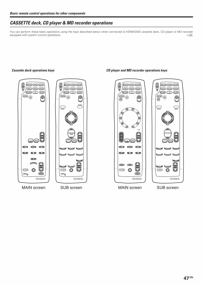
47 EN
Basic remote control operations for other components
CASSETTE deck, CD player & MD recorder operations
You can perform these basic operations using the keys described below when connected to KENWOOD cassette deck, CD player or MD recorderequipped with system control operations. ™
Cassette deck operations keys CD player and MD recorder operations keys
A
TUNE +BANDTUNE –
M. ZONE
LANG.AUTODIMMER
INFO. / DISP. TV / SATLAST CH.
AMESEEK
FLIP
DISC SEL.INPUT SEL.
DISC SKIPBYPASS A /
LEARN
SUB
MEMORYTV MUTE
+ 100 + 10
ENTER
P.C
ALL
P.CA
LL
9
4 5
0
81
2 7
3 6
CH SCAN
SRCPWR
MODE
RCVRPWROFF
ONC. SEARCH DIRECT
EXITGUIDE
OSD RETURN
TOP MENU MENU
A
TUNE +
ACT. EQ
BAND
SP. EQ
TUNE –
LOUD.
B. BOOST
M. ZONE
LANG.AUTO
STEREO
DIMMER
DSP MODE
INFO. / DISP. TV / SATLAST CH.
AMESEEK
THXFLIP
DISC SEL.INPUT SEL.
DISC SKIP
TONE INPUT M.
MAIN
MEMORYTV MUTE
+ 100 + 10
CH
PAGELISTEN MODE
ENTER
P.C
ALL
P.CA
LL
MULTI
MULTI
9
4 5
0
81
2 7
3 6
CH SCAN
SRCPWR
MODESETUP
SOUND
RCVRPWROFF
ONC. SEARCH DIRECT
EXITGUIDE
OSD RETURN
TOP MENU MENU
TAPE
MUTESUB
B
MD / TAPE
CD/DVD
VIDEO1 VIDEO2 VIDEO3
TUNERDVD/6CH
TV AV AUX
PHONOTV
PWRRCVR PWR
BYPASS A /
VOL
LEARN
TV INPUT
TV VOL
B
TAPE
MUTEMAIN
B
MD / TAPE
CD/DVD
VIDEO1 VIDEO2 VIDEO3
TUNERDVD/6CH
TV AV AUX
PHONO
SETUP
SOUND
TVPWR
RCVR PWR
ACT. EQSP. EQLOUD.
B. BOOSTSTEREO DSP MODE
THX
TONE INPUT M.
VOL
TV INPUT
B
CH
PAGELISTEN MODE
MULTI
MULTI
MAIN screen SUB screen
TV VOL
TAPEAB
TUNE +BANDTUNE –
M. ZONE
LANG.AUTODIMMER
INFO. / DISP. TV / SATLAST CH.
AMESEEK
FLIP
DISC SEL.INPUT SEL.
DISC SKIPBYPASS A /
LEARN
SUB
CH
PAGE
MEMORYTV MUTE
+ 100 + 10
P.C
ALL
P.CA
LL
ENTER
9
4 5
0
81
2 7
3 6
ON
CH SCAN SOUND
C. SEARCH DIRECT
EXITGUIDE
OSD RETURN
TOP MENU MENU
RCVRPWROFF
TAPEAB
TUNE +
ACT. EQ
BAND
SP. EQ
TUNE –
LOUD.
B. BOOST
M. ZONE
LANG.AUTO
STEREO
DIMMER
DSP MODE
INFO. / DISP. TV / SATLAST CH.
AMESEEK
THXFLIP
INPUT SEL.
TONE INPUT M.
BYPASS A /
MAIN
CH
PAGELISTEN MODE
MEMORYTV MUTE
P.C
ALL
P.CA
LL
MULTI
MULTI
ENTER
CH SCAN
MODESETUP
SOUND
C. SEARCH DIRECT
EXITGUIDE
OSD RETURN
TOP MENU MENU
ON
RCVRPWROFF
MUTESUB
MD / TAPE
CD/DVD
VIDEO1 VIDEO2 VIDEO3
TUNERDVD/6CH
TV AV AUX
PHONO
SRCPWR
TVPWR
RCVR PWR
DISC SEL. DISC SKIP
VOL
LEARN
TV INPUT
B
9
4 5
0
81
2 7
3 6
MUTEMAIN
MD / TAPE
CD/DVD
VIDEO1 VIDEO2 VIDEO3
TUNERDVD/6CH
TV AV AUX
PHONO
SRCPWR
MODESETUP
TVPWR
RCVR PWR
ACT. EQSP. EQLOUD.
B. BOOSTSTEREO DSP MODE
THX
TONE INPUT M.
VOL
TV INPUT
B
LISTEN MODE
MULTI
MULTI
MAIN screen SUB screen
TV VOL TV VOL
+ 10
*5341/40-52/EN 2003/03/19, 6:03 AM47

48 EN
Basic remote control operations for other components
Other components’ operations
Refer to the following for the type of remote control operations available for each component.
• When pressing keys in succession, press each key firmly and be sureto wait at least 1 second before pressing the next key.
• Numeric keys function the same as the numeric keys on the originalremote.
These keys can be used to perform the basic operations of KENWOOD and other manufacturers’ components which the setup code for
each component had been entered beforehand. e
TV operation keys VCR and PVR operation keys
1 Select the input source.
2 Press the keys corresponding to the operations you desire.
Refer to the following sections for details.
SRCPWR
TAPEAB
TUNE +BANDTUNE –
M. ZONE
LANG.AUTODIMMER
INFO. / DISP. TV / SATLAST CH.
AMESEEK
FLIP
DISC SEL.INPUT SEL.
DISC SKIPBYPASS A /
LEARN
PAGE
SUB
MEMORYTV MUTE
+ 100 + 10
ENTER
P.C
ALL
P.CA
LL
9
4 5
0
81
2 7
3 6
CH SCAN
SRCPWR
MODE
RCVRPWROFF
ONC. SEARCH DIRECT
EXITGUIDE
OSD RETURN
TOP MENU MENU
TAPEAB
TUNE +
ACT. EQ
BAND
SP. EQ
TUNE –
LOUD.
B. BOOST
M. ZONE
LANG.AUTO
STEREO
DIMMER
DSP MODE
TV / SATAMESEEK
THXFLIP
DISC SEL.INPUT SEL.
DISC SKIP
TONE INPUT M.
BYPASS A /
PAGELISTEN MODE
MAIN
MEMORY
+ 100
P.C
ALL
P.CA
LL
MULTI
MULTI
CH SCAN
MODESETUP
SOUND
RCVRPWROFF
ONC. SEARCH DIRECT
OSD RETURN
TOP MENU
MUTESUB
MD / TAPE
CD/DVD
VIDEO1 VIDEO2 VIDEO3
TUNERDVD/6CH
TV AV AUX
PHONOTV
PWRRCVR PWR
TV MUTE
INFO. / DISP.LAST CH.
VOL
EXITGUIDE
MENU
LEARN
TV INPUT
B
CH
ENTER
9
4 5
0
81
2 7
3 6
MUTEMAIN
MD / TAPE
CD/DVD
VIDEO1 VIDEO2 VIDEO3
TUNERDVD/6CH
TV AV AUX
PHONO
SETUP
SOUND
TVPWR
RCVR PWR
ACT. EQSP. EQLOUD.
B. BOOSTSTEREO DSP MODE
THX
TONE INPUT M.
VOL
TV INPUT
B
CH
LISTEN MODE
MULTI
MULTI
MAIN screen SUB screen
TV VOL TV VOL
+ 10
SUB
TAPEAB
MEMORYTV MUTE
TUNE +BANDTUNE –
M. ZONE
LANG.AUTODIMMER
INFO. / DISP. TV / SATLAST CH.
AMESEEK
FLIP
DISC SEL.INPUT SEL.
DISC SKIPBYPASS A /
+ 100 + 10
LEARN
P.C
ALL
P.CA
LL
ENTER
CH SCAN
MODE
RCVRPWROFF
ONC. SEARCH DIRECT
EXITGUIDE
OSD RETURN
TOP MENU MENU
9
4 5
0
81
2 7
3 6
TAPEAB
TUNE +
ACT. EQ
BAND
SP. EQ
TUNE –
LOUD.
B. BOOST
M. ZONE
LANG.AUTO
STEREO
DIMMER
DSP MODE
TV / SATAMESEEK
THXFLIP
DISC SEL. DISC SKIP
TONE INPUT M.
BYPASS A /
MAIN
MEMORYTV MUTE
+ 100
PAGELISTEN MODE
P.C
ALL
P.CA
LL
MULTI
MULTI
CH SCAN
MODESETUP
SOUND
RCVRPWROFF
ONC. SEARCH DIRECT
OSD RETURN
TOP MENU
MUTESUB
MD / TAPE
CD/DVD
VIDEO1 VIDEO2 VIDEO3
TUNERDVD/6CH
TV AV AUX
PHONO
SRCPWR
TVPWR
RCVR PWR
INFO. / DISP.LAST CH.
INPUT SEL.
VOL
EXITGUIDE
LEARN
TV INPUT
B
CH
ENTER
9
4 5
0
81
2 7
3 6
MUTEMAIN
MD / TAPE
CD/DVD
VIDEO1 VIDEO2 VIDEO3
TUNERDVD/6CH
TV AV AUX
PHONO
SRCPWR
SETUP
SOUND
TVPWR
RCVR PWR
ACT. EQSP. EQLOUD.
B. BOOSTSTEREO DSP MODE
THX
TONE INPUT M.
VOL
TV INPUT
B
CH
PAGELISTEN MODE
MULTI
MULTI
MENU
MAIN screen SUB screen
TV VOL TV VOL
+ 10
*5341/40-52/EN 2003/03/19, 6:03 AM48

49 EN
Basic remote control operations for other components
DSS operation keys Cable and DTV decorder operation keys
DVD player operation keys PHONO operations keys
TAPEAB
TUNE +BANDTUNE –
M. ZONE
LANG.AUTODIMMER
INFO. / DISP. TV / SATLAST CH.
AMESEEK
FLIP
DISC SEL.INPUT SEL.
DISC SKIPBYPASS A /
LEARN
SUB
MEMORYTV MUTE
+ 100 + 10
PAGE
ENTER
P.C
ALL
P.CA
LL
9
4 5
0
81
2 7
3 6
CH SCAN
MODE
RCVRPWROFF
ONC. SEARCH DIRECT
EXITGUIDE
OSD RETURN
TOP MENU MENU
TAPEAB
M. ZONE
AMESEEK
THXFLIP
DISC SEL.INPUT SEL.
DISC SKIP
TONE INPUT M.
BYPASS A /
MAIN
TUNE +
ACT. EQ
BAND
SP. EQ
TUNE –
LOUD.
B. BOOST
LANG.AUTO
STEREO
DIMMER
DSP MODE
LISTEN MODE
MEMORYTV MUTE
+ 100
P.C
ALL
P.CA
LL
MULTI
MULTI
CH SCAN
MODESETUP
SOUND
RCVRPWROFF
ONC. SEARCH DIRECT
OSD RETURN
TOP MENU
MUTESUB
MD / TAPE
CD/DVD
VIDEO1 VIDEO2 VIDEO3
TUNERDVD/6CH
TV AV AUX
PHONO
SRCPWR
TVPWR
RCVR PWR
INFO. / DISP. TV / SATLAST CH.
VOL
EXITGUIDE
MENU
TV INPUT
B
PAGE
ENTER
9
4 5
0
81
2 7
3 6
MUTEMAIN
MD / TAPE
CD/DVD
VIDEO1 VIDEO2 VIDEO3
TUNERDVD/6CH
TV AV AUX
PHONO
SRCPWR
SETUP
SOUND
TVPWR
RCVR PWR
ACT. EQSP. EQLOUD.
B. BOOSTSTEREO DSP MODE
THX
TONE INPUT M.
VOL
TV INPUT
B
CH
LISTEN MODE
MULTI
MULTI
LEARN
MAIN screen SUB screen
TV VOL TV VOL
CHCH
+ 1010
TAPEAB
TUNE +BANDTUNE –
M. ZONE
LANG.AUTODIMMER
INFO. / DISP. TV / SATLAST CH.
AMESEEK
FLIP
DISC SEL.INPUT SEL.
DISC SKIPBYPASS A /
LEARN
SUB
MEMORYTV MUTE
+ 100 + 10
PAGE
P.C
ALL
P.CA
LL
ENTER
9
4 5
0
81
2 7
3 6
CH SCAN
MODE
C. SEARCH DIRECT
EXITGUIDE
OSD RETURN
TOP MENU MENU
ON
RCVRPWROFF
TAPEAB
TUNE +
ACT. EQ
BAND
SP. EQ
TUNE –
LOUD.
B. BOOST
M. ZONE
LANG.AUTO
STEREO
DIMMER
DSP MODE
TV / SATAMESEEK
THXFLIP
DISC SEL.INPUT SEL.
DISC SKIP
TONE INPUT M.
MAIN
MEMORYTV MUTE
+ 100 + 10
LISTEN MODE
P.C
ALL
P.CA
LL
MULTI
MULTI
CH SCAN
MODESETUP
SOUND
RCVRPWROFF
ONC. SEARCH DIRECT
OSD RETURN
TOP MENU
MUTESUB
MD / TAPE
CD/DVD
VIDEO1 VIDEO2 VIDEO3
TUNERDVD/6CH
TV AV AUX
PHONO
SRCPWR
TVPWR
RCVR PWR
INFO. / DISP.LAST CH.
BYPASS A /
VOL
EXITGUIDE
MENU
LEARN
TV INPUT
B
PAGE
ENTER
9
4 5
0
81
2 7
3 6
MUTEMAIN
MD / TAPE
CD/DVD
VIDEO1 VIDEO2 VIDEO3
TUNERDVD/6CH
TV AV AUX
PHONO
SRCPWR
SETUP
SOUND
TVPWR
RCVR PWR
ACT. EQSP. EQLOUD.
B. BOOSTSTEREO DSP MODE
THX
TONE INPUT M.
VOL
TV INPUT
B
CH
LISTEN MODE
MULTI
MULTI
MAIN screen SUB screen
TV VOL TV VOL
CH
+ 1010
CH
P.C
ALL
P.CA
LL
MULTI
MULTI
TAPEAB
TUNE +BANDTUNE –
M. ZONE
LANG.AUTODIMMER
INFO. / DISP. TV / SATLAST CH.
AMESEEK
FLIP
DISC SEL.INPUT SEL.
DISC SKIPBYPASS A /
LEARN
CH
MEMORYTV MUTE
+ 100 + 10
SUB
PAGE
ENTER
P.C
ALL
P.CA
LL
9
4 5
0
81
2 7
3 6
CH SCAN
MODE
C. SEARCH DIRECT
EXITGUIDE
OSD RETURN
TOP MENU MENU
RCVRPWROFF
ON
TAPEAB
TUNE +
ACT. EQ
BAND
SP. EQ
TUNE –
LOUD.
B. BOOST
M. ZONE
LANG.AUTO
STEREO
DIMMER
DSP MODE
INFO. / DISP. TV / SATLAST CH.
AMESEEK
THX
INPUT SEL.
TONE INPUT M.
BYPASS A /
MAIN
LISTEN MODE
MEMORYTV MUTE
CH SCAN
MODESETUP
SOUND
C. SEARCH DIRECT
EXITGUIDE
ON
RCVRPWROFF
MUTESUB
MD / TAPE
CD/DVD
VIDEO1 VIDEO2 VIDEO3
TUNERDVD/6CH
TV AV AUX
PHONO
SRCPWR
TVPWR
RCVR PWR
FLIP
DISC SEL. DISC SKIP
VOL
OSD RETURN
TOP MENU MENU
LEARN
TV INPUT
B
PAGE
ENTER
9
4 5
0
81
2 7
3 6
MUTEMAIN
MD / TAPE
CD/DVD
VIDEO1 VIDEO2 VIDEO3
TUNERDVD/6CH
TV AV AUX
PHONO
SRCPWR
SETUP
SOUND
TVPWR
RCVR PWR
ACT. EQSP. EQLOUD.
B. BOOSTSTEREO DSP MODE
THX
TONE INPUT M.
VOL
TV INPUT
B
LISTEN MODE
MULTI
MULTI
MAIN screen SUB screen
TV VOL TV VOL
+ 10+ 100
TAPEAB
TUNE +BANDTUNE –
M. ZONE
LANG.AUTODIMMER
INFO. / DISP. TV / SATLAST CH.
AMESEEK
FLIP
DISC SEL.INPUT SEL.
DISC SKIPBYPASS A /
LEARN
P.C
ALL
P.CA
LL
RETURN
SUB
CH SCAN
SRCPWR
MODE
RCVRPWROFF
ON
MEMORYTV MUTE
C. SEARCH DIRECT
EXITGUIDE
OSD
TOP MENU MENU
+ 100 + 10
PAGE
ENTER
9
4 5
0
81
2 7
3 6
TAPEA
MAIN
B
SRCPWR
MEMORYTV MUTE
TUNE +
ACT. EQ
BAND
SP. EQ
TUNE –
LOUD.
B. BOOST
M. ZONE
LANG.AUTO
STEREO
DIMMER
DSP MODE
INFO. / DISP. TV / SATLAST CH.
AMESEEK
THXFLIP
DISC SEL.INPUT SEL.
DISC SKIP
TONE INPUT M.
BYPASS A /
+ 100 + 10
CH
PAGELISTEN MODE
CH SCAN
MODESETUP
SOUND
RCVRPWROFF
ONC. SEARCH DIRECT
EXITGUIDE
OSD RETURN
TOP MENU MENU
P.C
ALL
P.CA
LL
MULTI
MULTI
ENTER
9
4 5
0
81
2 7
3 6
MUTESUB
MD / TAPE
CD/DVD
VIDEO1 VIDEO2 VIDEO3
TUNERDVD/6CH
TV AV AUX
PHONOTV
PWRRCVR PWR
VOL
LEARN
TV INPUT
B
MUTEMAIN
MD / TAPE
CD/DVD
VIDEO1 VIDEO2 VIDEO3
TUNERDVD/6CH
TV AV AUX
PHONO
SETUP
SOUND
TVPWR
RCVR PWR
ACT. EQSP. EQLOUD.
B. BOOSTSTEREO DSP MODE
THX
TONE INPUT M.
VOL
TV INPUT
B
CH
LISTEN MODE
MULTI
MULTI
MAIN screen SUB screen
TV VOL TV VOL
*5341/40-52/EN 2003/03/19, 6:03 AM49

50 EN
In case of difficulty
Tuner
Cause
• No antenna is connected.• The broadcast band is not set properly.• The frequency of the desired station is not
tuned.
• Noise due to ignition noise from an automobile.• Noise due to interference from an electric
appliance.• Noise due to a nearby TV set.
• The preset station belongs to a frequency thatcannot be received.
• The preset memory was cleared because thepower cord had been unplugged for a longperiod of time.
Remedy
• Connect an antenna. ¡• Set the broadcast band properly.• Tune the frequency of the desired station.
º
• Install the outdoor antenna away from theroad.
• Turn off the power to the appliance.
• Install the receiver farther away from the TV.
• Preset a station with a receivable frequency.
• Preset the station again.
Symptom
Radio stations cannot be received.
Interference.
A station which was preset cannot be
received by pressing the corresponding
numeric key.
Amplifier
Cause
• The speaker cords are disconnected.
• VOLUME is set to the minimum position.• MUTE is ON.• The SPEAKERS switches are set to OFF.
• Speaker cords are short-circuited.
• The speaker cord is disconnected.
• The surround speaker cords and/or the centerspeaker cord is disconnected.
• A surround mode has not been engaged.• The surround and/or center volume controls
are set to the minimum level.
• The audio cord from the record player is notconnected to the PHONO jacks.
• The record player is not grounded.
• There are many possible causes for thisproblem, depending on the type of DVD playerused.
• The input mode is set to digital manual.
• The software is copy-guarded.
Remedy
• Connect them properly referring to“Connecting the speakers” &
• Adjust the volume to a proper level.• Turn OFF the MUTE. ¶• Set the SPEAKERS switches to ON. §
• Turn the power off, eliminate the short-circuiting, then turn on the power again.
• Connect it properly referring to “Connectingthe speakers”. &
• Connect it properly referring to “Connectingthe speakers”. &
• Select a surround mode.• Adjust the speaker levels using the test tone.
¢
• Insert the audio cord plugs securely into thePHONO jacks.
• Connect the grounding wire to the GNDterminal on the rear panel.
• Set the input mode to digital manual beforestarting playback of the Dolby Digital source.
0
• Press the INPUT MODE key to select to fullauto mode. 0
• Copy-guarded video software cannot berecorded.
Symptom
No sound from the speakers.
The standby indicator blinks and sound is
not output.
Sound is not output from one of the speakers.
Sound is not output from the surround
speakers and / or the center speaker, or their
sound is very small.
A humming noise is generated when the
PHONO input selector is selected.
When playing a Dolby Digital source signal
using a DVD player, the sound is cut off soon
after it starts.
No sound is produced during playback from
a DVD player.
A video source cannot be recordednormally.
Resetting the MicrocomputerThe microcomputer may malfunction (unit cannot be
operated, or shows an erroneous display) if the power cord is
unplugged while the power is ON, or due to some other
external factor. If this happens, execute the following
procedure to reset the microcomputer and return the unit to
its normal operating condition.
• Please note that resetting the microcomputer will clear the contentsof the memory and returns the unit to the state it was in when it leftthe factory.
For U.S.A. and Canada
Unplug the power cord from the wall outlet, then plug it
back in while holding down the POWER ON/STANDBY
key.
For other countries
With the power cord plugged in, turn the POWER key OFF.
Then, while holding down the ON/STANDBY key, press
POWER key.
*5341/40-52/EN 2003/03/19, 6:03 AM50

51 EN
Remote control unit
Cause
• No setup codes registered for the respectiveinput(s).
• The remote control is set to a different operationmode.
• Batteries are exhausted.• The remote control unit is too far away from
the main system, controlling angle is too large,or there is an obstacle between the receiverand the remote.
• The audio cords and system control cords arenot connected properly.
• No tape or CD is placed in the sourcecomponent.
• An attempt is made to play a tape which isbeing recorded in the cassette deck.
• The remote control has not been set to theoperation mode for the component you wishto control.
Remedy
• Register a setup code at the respective input(s).e
• Press the Input selector keys to select theappropriate operation mode.
• Replace with new batteries.• Operate the remote control unit within the
controllable range.
• Connect properly referring to “Setting up thesystem”.
• Place the tape or CD in the source componentwhich you want to play.
• Wait until recording has completed.
• Press any of the source keys or SRC PWR keyto activate the operation mode for thecomponent you want to control beforeoperation. q
Symptom
Certain inputs cannot be selected using the
remote control.
Remote control operation is not possible.
In case of difficulty
*5341/40-52/EN 2003/03/19, 6:03 AM51

52 EN
For your recordsRecord the serial number, found on the back of the unit, in the spacesdesignated on the warranty card, and in the space provided below. Referto the model and serial numbers whenever you call upon your dealer forinformation or service on this product.
Model__________________ Serial Number ________________________
Notes1. KENWOOD follows a policy of continuous advancements in development. For this reason specifications may be changed without notice.2. The full performance may not be exhibited in an extremely cold location (under a water-freezing temperature).
SpecificationsAUDIO sectionRated power output during STEREO operation
Effective power output during SURROUND operation (VR-7080)
FRONT (20 Hz ~ 20 kHz, 0.09 % T.H.D. at 8 Ω one channel driven)............................................................................... 100 W + 100 W
CENTER (20 Hz ~ 20 kHz, 0.09 % T.H.D. at 8 Ω one channeldriven) .................................................................................. 100 WSURROUND (20 Hz ~ 20 kHz, 0.7 % T.H.D. at 8 Ω one channeldriven) ................................................................... 100 W + 100 WSURROUND BACK/SUBWOOFER (20 ~ 20 kHz, 0.09 % T.H.D.at 8 Ω one channel driven) ................................................. 100 W
Effective power output during SURROUND operation (KRF-X9070D)FRONT (20 Hz ~ 20 kHz, 0.09 % T.H.D. at 8 Ω one channel driven)............................................................................... 100 W + 100 W
FRONT (1 kHz, 10 % T.H.D. at 8 Ω one channel driven)............................................................................... 130 W + 130 W
CENTER (20 Hz ~ 20 kHz, 0.09 % T.H.D. at 8 Ω one channeldriven) .................................................................................. 100 WCENTER (1 kHz, 10 % T.H.D. at 8 Ω one channel driven).............................................................................................. 130 W
SURROUND (20 Hz ~ 20 kHz, 0.7 % T.H.D. at 8 W one channeldriven) ................................................................... 100 W + 100 WSURROUND (1 kHz, 10 % T.H.D. at 8 Ω one channel driven)............................................................................... 130 W + 130 W
SURROUND BACK/SUBWOOFER (20 ~ 20 kHz, 0.09 % T.H.D.at 8 W one channel driven) ................................................ 100 WSURROUND BACK/SUBWOOFER (1 kHz, 10 % T.H.D. at 8 Ωone channel driven) ............................................................ 130 W
Total harmonic distortion ....................... 0.009 % (1 kHz, 50 W, 8 Ω)Frequency response
Line (CD/DVD, TAPE, VIDEO 1, VIDEO 2, VIDEO 3, DVD/6CH)................................................... 10 Hz ~ 100 kHz, 0 dB ~ –3.0 dB
PHONO ‘RIAA’ response .............. 40 Hz ~ 20 kHz, +1.5 dB ~ –3.0 dBMaximum input level
PHONO (MM) ....................................45 mV, 1 % T.H.D. at 1 kHzSignal to noise ratio (IHF’66)
PHONO (MM) ........................................................................ 75 dBLine (CD/DVD, TAPE, VIDEO 1, VIDEO 2, VIDEO 3, DVD/6CH)............................................................................................... 95 dB
Loudness controlVOLUME at –30 dB level ...................................... +6 dB (100 Hz)
Input sensitivity / impedancePHONO (MM) ........................................................... 4 mV / 47 kΩLine (CD/DVD, TAPE, VIDEO 1, VIDEO 2, VIDEO 3, DVD/6CH).............................................................................. 320 mV / 47 kΩ
Output level / impedanceTAPE REC ............................................................... 320 mV / 1 kΩPRE OUT (FRONT, CENTER, SURROUND) ...............1 V / 500 ΩPRE OUT (SURROUND BACK ) ................................. 1 V / 500 ΩPRE OUT (SUBWOOFER) .......................................... 1 V / 500 Ω
Tone controlBASS................................................................ ±10 dB (at 100 Hz)TREBLE ............................................................ ±10 dB (at 10 kHz)
DIGITAL AUDIO sectionSampling frequency ...................... 32 kHz, 44.1 kHz, 48 kHz, 96 kHzInput level / impedance / wave length
Optical ........................... (–15 dBm ~ –24 dBm), 660 nm ±30 nmCoaxial ................................................................... 0.5 Vp-p / 75 Ω
Output level / impedance / wave lengthOptical ........................... (–21 dBm ~ –15 dBm), 660 nm ±30 nm
100 watts per channel minimum RMS, both channels driven,at 8 Ω from 20 Hz to 20 kHz with no more than 0.09% totalharmonic distortion. (FTC)
VIDEO sectionVIDEO inputs / outputs
VIDEO (composite) .................................................. 1 Vp-p / 75 ΩS-VIDEO inputs /outputs
S-VIDEO (luminance signal) ................................... 1 Vp-p / 75 ΩS-VIDEO (chrominance signal) ...................... 0.286 Vp-p / 75 Ω
COMPONENT VIDEO inputs /outputsCOMPONENT VIDEO (luminance signal) .............. 1 Vp-p / 75 ΩCOMPONENT VIDEO (CB/CR-signal) ............ ±0.32 Vp-p / 75 Ω
FM tuner sectionTuning frequency range................................. 87.5 MHz ~ 108.0 MHz
Usable sensitivity (MONO)......................... 1.3 µV (75 W)/ 13.2 dBf (75 kHz dev, SINAD 30 dB)50 dB quieting sensitivity
STEREO ..................................................... 28 µV (75 Ω)/ 40.2 dBfTotal harmonic distortion
MONO (1 kHz, 75 kHz dev) .......................... 0.5% (65 dBf input)STEREO (1 kHz, 67.5 + 6.75 kHz dev) ......... 0.7% (65 dBf input)
Signal to noise ratioMONO (1 kHz, 75 kHz dev) ........................ 75 dB (65 dBf input)STEREO (1 kHz, 67.5 + 6.75 kHz dev) ....... 68 dB (65 dBf input)
Stereo separation (1 kHz) ........................................................... 40 dBSelectivity (±400 kHz) (VR-7080) ............................................... 70 dB
(KRF-X9070D) ........................................ 50 dBFrequency response (30 Hz ~ 15 kHz) .................... +0.5 dB, –3.0 dB
AM tuner sectionTuning frequency range
10 kHz step ................................ 530 kHz ~ 1,700 kHz (VR-7080)10 kHz step ......................... 530 kHz ~ 1,610 kHz (KRF-X9070D)9 kHz step ........................... 531 kHz ~ 1,602 kHz (KRF-X9070D)
Usable sensitivity (30% mod, S/N 20 dB) ......... 16 µV / (600 µV/m)Signal to noise ratio (30% mod, 400 Hz)................................................................. 50 dB (60 dB µV EMF input)
GENERALPower consumption VR-7080 ..................................................... 3 A
KRF-X9070D ......................................... 300 WStandby Power consumption ....................................... less than 2WAC outlet
SWITCHED VR-7080 ...................... (total 150 W, 1.25 A max.)KRF-X9070D ....................................... (total 90 W)
Dimensions ..................................................... W : 440 mm (17-5/16")H : 159 mm (6-1/4")D : 392 mm (15-7/16")
Weight (Net)VR-7080 ................................................................ 9.4 kg (20.7 lb)KRF-X9070D ........................................................ 10.2 kg (22.5 lb)
Caution : Read this page carefully to ensure safeoperation.
*5341/40-52/EN 2003/03/19, 6:03 AM52