audio ei3 extender board manual - analog.com · trademark and service mark notice the analog...
TRANSCRIPT
a
Audio EI3 Extender Board Manualan EZ-Extender® product
Revision 1.0, April 2012
Part Number 82-000300-01
Analog Devices, Inc.One Technology WayNorwood, Mass. 02062-9106
Copyright Information©2012 Analog Devices, Inc., ALL RIGHTS RESERVED. This document may not be reproduced in any form without prior, express written consent from Analog Devices, Inc.
Printed in the USA.
DisclaimerAnalog Devices, Inc. reserves the right to change this product without prior notice. Information furnished by Analog Devices is believed to be accurate and reliable. However, no responsibility is assumed by Analog Devices for its use; nor for any infringement of patents or other rights of third parties which may result from its use. No license is granted by impli-cation or otherwise under the patent rights of Analog Devices, Inc.
Trademark and Service Mark NoticeThe Analog Devices logo, Blackfin, CrossCore, EZ-Board, EZ-Extender, EZ-KIT Lite, and SigmaDSP are registered trademarks of Analog Devices, Inc.
EngineerZone is a trademark of Analog Devices, Inc.
All other brand and product names are trademarks or service marks of their respective owners.

Regulatory Compliance The Audio EI3 Extender Board is designed to be used solely in a labora-tory environment. The board is not intended for use as a consumer end product or as a portion of a consumer end product. The board is an open system design which does not include a shielded enclosure and therefore may cause interference to other electrical devices in close proximity. This board should not be used in or near any medical equipment or RF devices.
The Audio EI3 Extender Board is in the process of being certified to com-ply with the essential requirements of the European EMC directive 89/336/EEC (inclusive 93/68/EEC) and, therefore, carries the “CE” mark.
The extender board contains ESD (electrostatic discharge) sensitive devices. Electrostatic charges readily accumulate on the human body and equipment and can discharge without detection. Permanent damage may occur on devices subjected to high-energy discharges. Proper ESD precautions are recommended to avoid performance degradation or loss of functionality. Store unused extender boards in the protective shipping package.

CONTENTS
PREFACE
Product Overview ........................................................................ vii
Purpose of This Manual .............................................................. viii
Intended Audience ...................................................................... viii
Manual Contents .......................................................................... ix
What’s New in This Manual ........................................................... x
Technical Support .......................................................................... x
Supported Products ....................................................................... xi
Product Information ..................................................................... xi
Analog Devices Web Site ......................................................... xi
EngineerZone ......................................................................... xii
Related Documents ..................................................................... xiii
Notation Conventions .................................................................. xiv
USING AUDIO EI3 EXTENDER BOARD
Package Contents .......................................................................... 1-2
Supported Operating Systems ........................................................ 1-2
System Requirements .................................................................... 1-3
Audio EI3 Extender Board Setup ................................................... 1-3
Audio EI3 Extender Board Manual v
Contents
Audio Interface ............................................................................. 1-4
Connectors ................................................................................... 1-4
Power LED (LED1) ...................................................................... 1-6
Power ........................................................................................... 1-6
AUDIO EI3 EXTENDER BOARD BILL OF MATERIALS
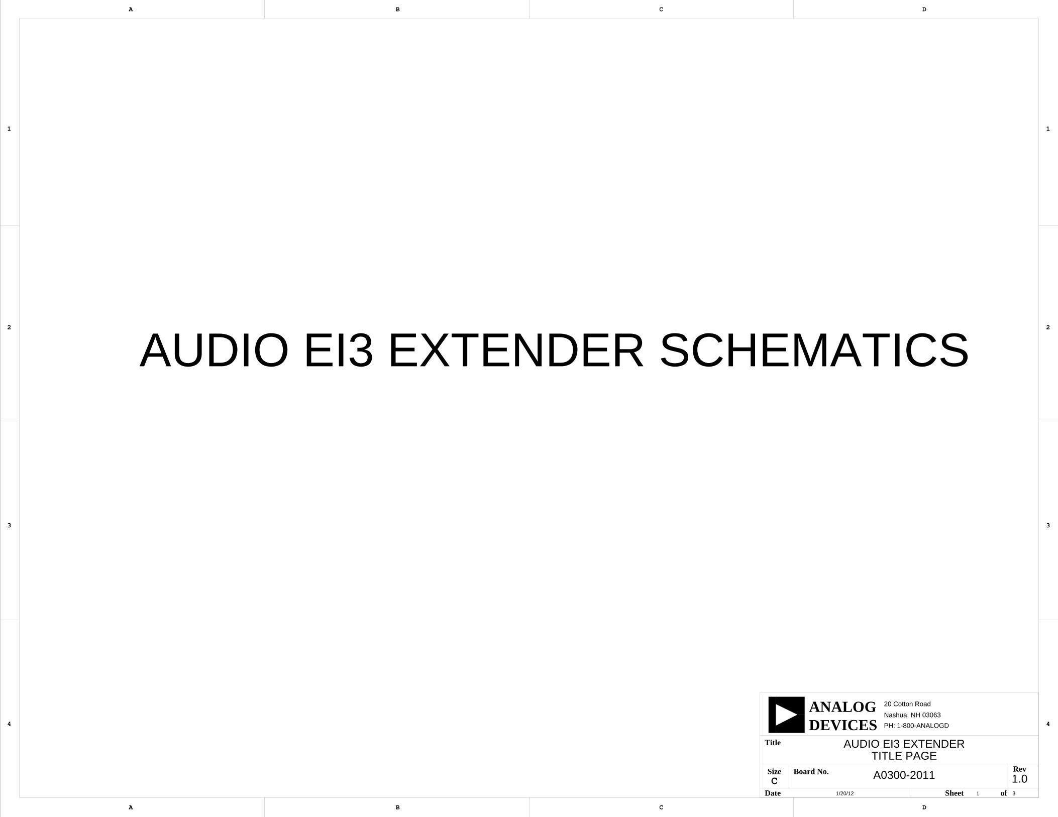
AUDIO EI3 EXTENDER BOARD SCHEMATIC
Title Page ..................................................................................... B-1
EI3 Conn, ADAU1761 ................................................................. B-2
Power, LED .................................................................................. B-3
INDEX
vi Audio EI3 Extender Board Manual
PREFACE
Thank you for purchasing the Audio EI3 Extender Board, an
EZ-Extender® product for EZ-KIT Lite®/EZ-Board® evaluation systems.The EZ-KIT Lite/EZ-Board and Audio EI3 Extender Board are designed to be used in conjunction with the CrossCore® Embedded Studio devel-opment environment. CrossCore Embedded Studio (CCES) offers a powerful programming tool with new flexibility that significantly decreases the time required to port software code to a processor, reducing time-to-market.
To learn more about Analog Devices development software, go to http://www.analog.com/processors/tools.
Product OverviewThe Audio EI3 Extender Board is a separately sold daughter board that plugs onto the expansion interface (EI3) of an EZ-KIT Lite/EZ-Board evaluation system. The extender board aids the design and prototyping phases of the embedded processor-targeted applications. For more infor-mation refer to the product website, http://www.analog.com/EI3-Audio.
The Audio EI3 Extender Board utilizes the ADAU1761 SigmaDSP® stereo, low power, 96 kHz, 24-bit audio codec. The codec provides line input, line output, auxiliary input and headphone output.
Audio EI3 Extender Board Manual vii
Purpose of This Manual
The following is a list of the Audio EI3 Extender Board interfaces.
• 3.5 mm line input connector (J4)
• 3.5 mm line output connector (J3)
• 3.5 mm auxiliary input (J5)
• 3.5 mm headphone (J2)
• Two omnidirectional MEMs microphones (U3 and U4)
Before using any of the interfaces, follow the setup procedure in “Audio EI3 Extender Board Setup” on page 1-3.
Example programs are available to demonstrate capabilities of the Audio EI3 Extender Board.
Purpose of This ManualThe Audio EI3 Extender Board Manual describes operation and configura-tion of the extender board components. A schematic and a bill of materials are provided as a reference guide for future processor board designs.
Intended AudienceThe primary audience for this manual is a programmer who is familiar with Analog Devices processors. This manual assumes that the audience has a working knowledge of the appropriate processor architecture, instruction set, and C/C++ programming languages.
Programmers who are unfamiliar with Analog Devices processors can use this manual, but should supplement it with other texts that describe your target architecture and hardware development tools.
viii Audio EI3 Extender Board Manual
Preface
Programmers who are unfamiliar with the CrossCore Embedded Studio programming environment or the mating evaluation board, should refer to the CCES online help or the manual describing the board (see “Related Documents”).
Manual ContentsThe manual consists of:
• Chapter 1, “Using Audio EI3 Extender Board” on page 1-1 Provides basic board information.
• Appendix A, “Audio EI3 Extender Board Bill Of Materials” on page A-1 Provides a list of hardware components used to manufacture the EZ-Extender board.
• Appendix B, “Audio EI3 Extender Board Schematic” on page B-1 Provides all of the circuits on the extender board.
Audio EI3 Extender Board Manual ix
What’s New in This Manual
What’s New in This ManualThis is the first revision of the Audio EI3 Extender Board Manual.
Technical SupportYou can reach Analog Devices processors and DSP technical support in the following ways:
• Post your questions in the processors and DSP support community at EngineerZoneTM: http://ez.analog.com/community/dsp
• Submit your questions to technical support directly at: http://www.analog.com/support
• E-mail your questions about processors, DSPs, and tools develop-ment software from CrossCore Embedded Studio or VisualDSP++:
Choose Help > Email Support. This creates an e-mail to [email protected] and automatically attaches your CrossCore Embedded Studio or VisualDSP++ version infor-mation and license.dat file.
• E-mail your questions about processors and processor applications to: [email protected] or [email protected] (Greater China support)
• In the USA only, call 1-800-ANALOGD (1-800-262-5643)
x Audio EI3 Extender Board Manual
Preface
• Contact your Analog Devices sales office or authorized distributor. Locate one at: www.analog.com/adi-sales
• Send questions by mail to: Processors and DSP Technical Support Analog Devices, Inc. Three Technology Way P.O. Box 9106 Norwood, MA 02062-9106 USA
Supported ProductsThis extender board supports the Expansion Interface 3 (EI3), and requires TWI and SPORT interfaces. When connecting to the ADSP-BF609 EZ-KIT Lite, use connector P1A, P1B, P2A, or P3A.
Product InformationProduct information can be obtained from the Analog Devices Web site and the CCES online help system.
Analog Devices Web SiteThe Analog Devices Web site, www.analog.com, provides information about a broad range of products—analog integrated circuits, amplifiers, converters, and digital signal processors.
To access a complete technical library for each processor family, go to http://www.analog.com/processors/technical_library. The manuals selection opens a list of current manuals related to the product as well as a link to the previous revisions of the manuals. When locating your manual
Audio EI3 Extender Board Manual xi
Product Information
title, note a possible errata check mark next to the title that leads to the current correction report against the manual.
Also note, myAnalog.com is a free feature of the Analog Devices Web site that allows customization of a Web page to display only the latest infor-mation about products you are interested in. You can choose to receive weekly e-mail notifications containing updates to the Web pages that meet your interests, including documentation errata against all manuals. myAnalog.com provides access to books, application notes, data sheets, code examples, and more.
Visit myAnalog.com (found on the Analog Devices home page) to sign up. If you are a registered user, just log on. Your user name is your e-mail address.
EngineerZoneEngineerZone is a technical support forum from Analog Devices. It allows you direct access to ADI technical support engineers. You can search FAQs and technical information to get quick answers to your embedded processing and DSP design questions.
Use EngineerZone to connect with other DSP developers who face similar design challenges. You can also use this open forum to share knowledge and collaborate with the ADI support team and your peers. Visit http://ez.analog.com to sign up.
xii Audio EI3 Extender Board Manual
Preface
Related DocumentsFor additional information about the product, refer to the following publications.
Table 1. Related Processor Publications
Title Description
Processor Data Sheet General functional description, pinout, and timing of the processor
Processor Hardware Reference Description of the internal processor archi-tecture and all register functions
Blackfin Processor Programming Reference Description of all allowed processor assembly instructions
Table 2. Related CCES Publications
Title Description
ADSP-BF60x EZ-KIT Lite Evaluation System Manual
Description of the boards’ interfaces and hardware components
CrossCore Embedded Studio Licensing Guide Description of the product’s licensing options, installation, and activation
CrossCore Embedded Studio Assembler and Preprocessor Manual
Description of the assembler functions and commands
CrossCore Embedded Studio C/C++ Complier and Library Manual for Blackfin Processors
Description of the complier functions and commands for Blackfin processors
CrossCore Embedded Studio Linker and Utilities Manual
Description of the linker functions and com-mands
CrossCore Embedded Studio Loader and Utilities Manual
Description of the loader/splitter functions and commands
Audio EI3 Extender Board Manual xiii

Notation Conventions
Notation ConventionsText conventions used in this manual are identified and described as follows.
Example Description
Close command (File menu)
Titles in reference sections indicate the location of an item within the CCES environment’s menu system (for example, the Close command appears on the File menu).
{this | that} Alternative required items in syntax descriptions appear within curly brackets and separated by vertical bars; read the example as this or that. One or the other is required.
[this | that] Optional items in syntax descriptions appear within brackets and sepa-rated by vertical bars; read the example as an optional this or that.
[this,…] Optional item lists in syntax descriptions appear within brackets delim-ited by commas and terminated with an ellipse; read the example as an optional comma-separated list of this.
.SECTION Commands, directives, keywords, and feature names are in text with letter gothic font.
filename Non-keyword placeholders appear in text with italic style format.
Note: For correct operation, ... A Note provides supplementary information on a related topic. In the online version of this book, the word Note appears instead of this
symbol.
Caution: Incorrect device operation may result if ... Caution: Device damage may result if ... A Caution identifies conditions or inappropriate usage of the product that could lead to undesirable results or product damage. In the online version of this book, the word Caution appears instead of this symbol.
Warning: Injury to device users may result if ... A Warning identifies conditions or inappropriate usage of the product that could lead to conditions that are potentially hazardous for the devices users. In the online version of this book, the word Warning appears instead of this symbol.
xiv Audio EI3 Extender Board Manual
1 USING AUDIO EI3 EXTENDER BOARD
This chapter provides the Audio EI3 Extender Board setup procedure and
describes the interfaces the extender supports.The information is presented in the following order.
• “Package Contents” on page 1-2
• “Supported Operating Systems” on page 1-2
• “System Requirements” on page 1-3
• “Audio EI3 Extender Board Setup” on page 1-3
• “Audio Interface” on page 1-4
• “Connectors” on page 1-4
• “Power LED (LED1)” on page 1-6
• “Power” on page 1-6
Audio EI3 Extender Board Manual 1-1
Package Contents
Package ContentsYour Audio EI3 Extender Board package contains the following items.
• Audio EI3 Extender Board
• A bag containing hardware for securing the extender board on the EZ-KIT Lite/EZ-Board
• One 3.5 mm male/male cable
• One set of stereo headphones
• Release note containing information about the product download
Contact the vendor where you purchased your extender board or contact Analog Devices, Inc. if any item is missing.
Supported Operating SystemsCCES is supported on the following operating systems:
• Windows® XP Professional SP3 (32-bit only)
• Windows Vista™ Business, Enterprise, or Ultimate SP2 (32-bit only)
• Windows 7 Professional, Enterprise, or Ultimate (32- and 64-bit)
Windows Vista and Windows 7 users may experience User Access Control (UAC) related errors if the software is installed into a pro-tected location, such as Program Files or Program Files (x86). We recommend installing the software in a non-UAC-protected location.
1-2 Audio EI3 Extender Board Manual
Using Audio EI3 Extender Board
System RequirementsVerify that your PC has these minimum requirements for the CCSE installation:
• 2 GHz single-core processor
• 1 GB RAM
• 8 GB available disk space
• One open USB port
A faster disk drive decreases the build time, especially for a large amount of source files.
Audio EI3 Extender Board SetupThe Audio EI3 Extender Board does not have any configuration that is required. Make sure the EZ-KIT Lite/EZ-Board that the Audio EI3 Extender Board will be connected to is set up properly.
Before powering the board, use the provided hardware to secure the extender to the EZ-KIT Lite/EZ-Board. The small spacers are intended for between the extender board and the mating board. If used, standoffs on the EZ-KIT Lite/EZ-Board may need to be removed. The extender board uses shorter standoffs and a screw secures these standoffs.
Refer to the readme text files in the CrossCore Embedded Studio direc-tory (<install_path>\Audio_EI3_Extender_Board-RelX.X.X\Audio_EI3, where X.X.X denotes the support package release number) for information on how to configure the EZ-KIT Lite boards. For more information on the Audio EI3 Extender Board, please go to http://www.analog.com/ EI3-Audio. The board support package (BSP) for the Audio EI3 Extender Board can be found at this website.
Audio EI3 Extender Board Manual 1-3
Audio Interface
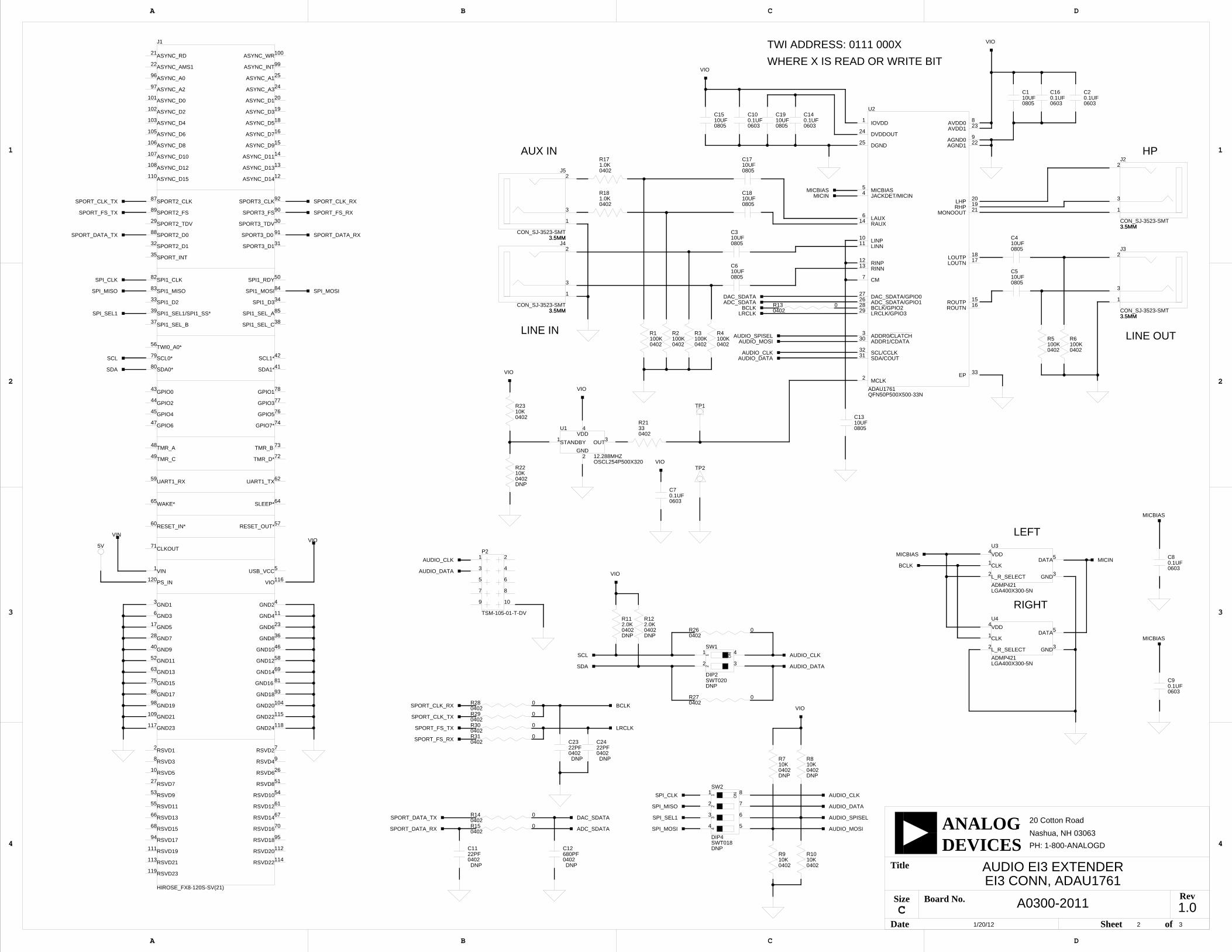
Audio InterfaceThe SigmaDSP ADAU1761 (U2) connects to the SPORT interface of the EI3 connector (J1). All control and setup communication uses the TWI interface. The TWI address is set to 0111 000X (where X is the read or write bit) by resistors R9 and R10. The last two address bits can be adjusted through populating R7 and/or R8, in conjunction with depopu-lating R9 and/or R10.
There are two input connectors and two output connectors. J2 is the ste-reo headphone output. J3 is line out and is a single-ended stereo output. J5 is the auxiliary input. J4 connects a single-ended stereo line in to the codec. A standard 3.5 mm male-to-male cable connects to any of these four connectors.
The board also has two omnidirectional MEMS microphones, which are Analog Devices part number ADMP421 ICs (U3 and U4). The micro-phones connect gluelessly to the ADAU1761 processor.
Example programs demonstrating the audio interface capabilities are included in the CrossCore Embedded Studio directory. Once installed, the example programs can be found in the <install_path>\Audio_EI3_ Extender_Board-RelX.X.X\Audio_EI3 directory, where X.X.X denotes the support package release number.
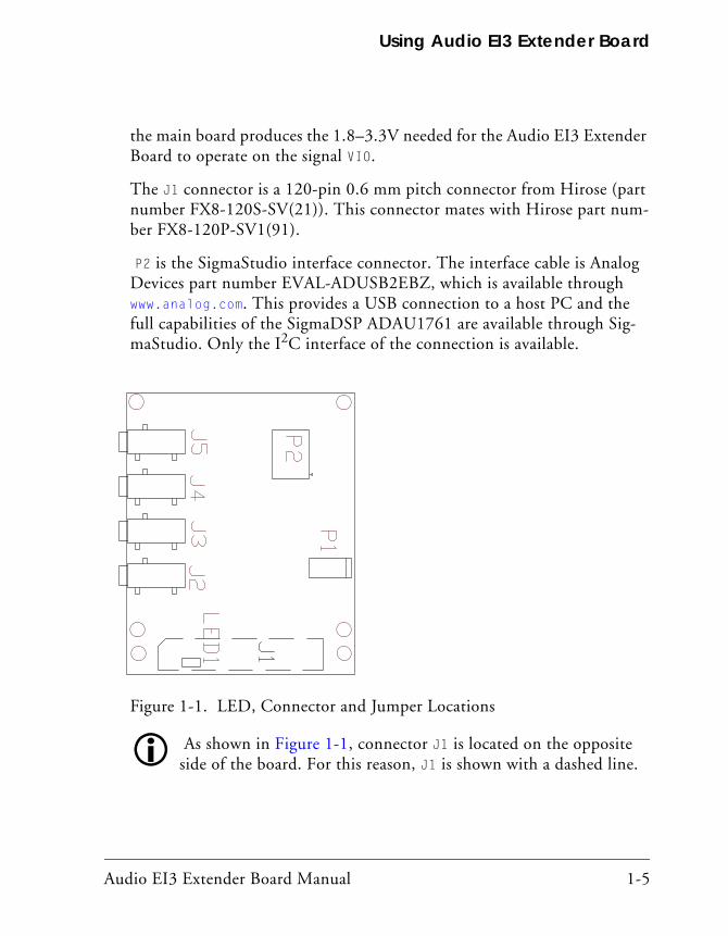
ConnectorsThe LED, connector, and jumper locations are shown in Figure 1-1.
The J2–J5 connectors are 3.5 mm stereo jacks from CUI Inc. (part num-ber SJ-3523-SMT). Use any 3.5 mm audio cable to connect to J2–J5.
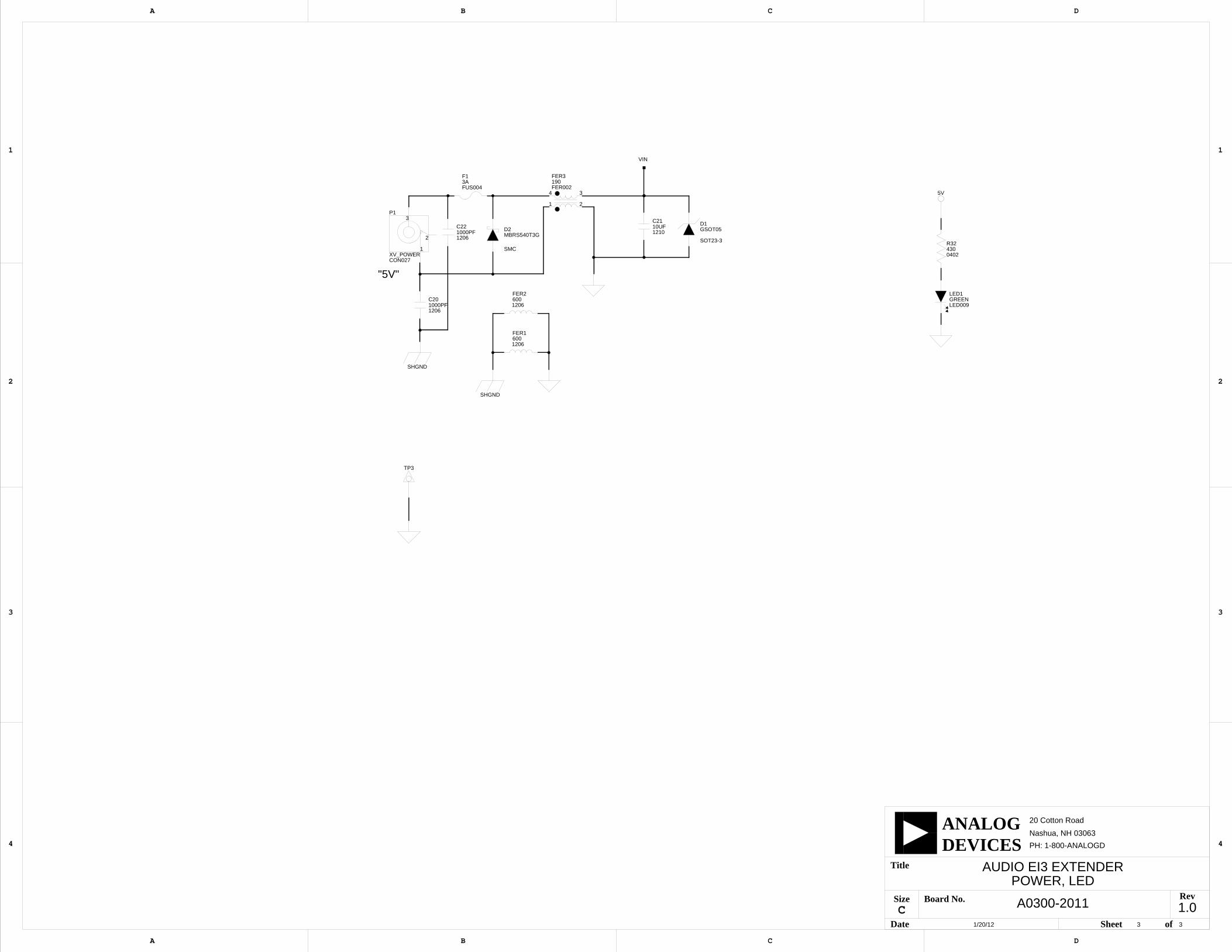
The P1 connector is a 0.65 mm power jack from CUI Inc. (part number CP1-022PJTR-ND). Use this jack when the EZ-KIT Lite/EZ-Board can-not provide adequate power. The 5V adaptor is then connected to P1 and
1-4 Audio EI3 Extender Board Manual
Using Audio EI3 Extender Board
the main board produces the 1.8–3.3V needed for the Audio EI3 Extender Board to operate on the signal VIO.
The J1 connector is a 120-pin 0.6 mm pitch connector from Hirose (part number FX8-120S-SV(21)). This connector mates with Hirose part num-ber FX8-120P-SV1(91).
P2 is the SigmaStudio interface connector. The interface cable is Analog Devices part number EVAL-ADUSB2EBZ, which is available through www.analog.com. This provides a USB connection to a host PC and the full capabilities of the SigmaDSP ADAU1761 are available through Sig-maStudio. Only the I2C interface of the connection is available.
As shown in Figure 1-1, connector J1 is located on the opposite side of the board. For this reason, J1 is shown with a dashed line.
Figure 1-1. LED, Connector and Jumper Locations
Audio EI3 Extender Board Manual 1-5
Power LED (LED1)
Power LED (LED1)The power LED (LED1) is located on the bottom of the board and is green when the Audio EI3 Extender Board is powered.
PowerThe Audio EI3 Audio Extender Board needs the EZ-KIT Lite/EZ-Board to be powered and does not require power input to the P2 power connector.
The VIO power rail of the Audio EI3 Extender Board must be in the range of 1.8V–3.3V for proper operation. Ensure that any main board con-nected to the Audio EI3 Extender Board supplies this voltage over pin 116 of J1.
1-6 Audio EI3 Extender Board Manual
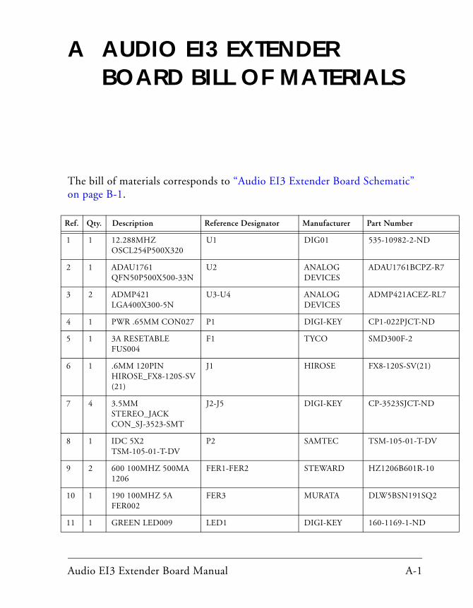
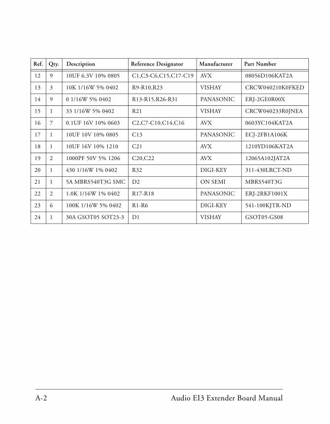
A AUDIO EI3 EXTENDER BOARD BILL OF MATERIALS
The bill of materials corresponds to “Audio EI3 Extender Board Schematic”
-R7
RL7
V
2
on page B-1.
Ref. Qty. Description Reference Designator Manufacturer Part Number
1 1 12.288MHZ OSCL254P500X320
U1 DIG01 535-10982-2-ND
2 1 ADAU1761 QFN50P500X500-33N
U2 ANALOG DEVICES
ADAU1761BCPZ
3 2 ADMP421 LGA400X300-5N
U3-U4 ANALOG DEVICES
ADMP421ACEZ-
4 1 PWR .65MM CON027 P1 DIGI-KEY CP1-022PJCT-ND
5 1 3A RESETABLE FUS004
F1 TYCO SMD300F-2
6 1 .6MM 120PIN HIROSE_FX8-120S-SV(21)
J1 HIROSE FX8-120S-SV(21)
7 4 3.5MM STEREO_JACK CON_SJ-3523-SMT
J2-J5 DIGI-KEY CP-3523SJCT-ND
8 1 IDC 5X2 TSM-105-01-T-DV
P2 SAMTEC TSM-105-01-T-D
9 2 600 100MHZ 500MA 1206
FER1-FER2 STEWARD HZ1206B601R-10
10 1 190 100MHZ 5A FER002
FER3 MURATA DLW5BSN191SQ
11 1 GREEN LED009 LED1 DIGI-KEY 160-1169-1-ND
Audio EI3 Extender Board Manual A-1
A
KED
NEA
A
12 9 10UF 6.3V 10% 0805 C1,C3-C6,C15,C17-C19 AVX 08056D106KAT2
13 3 10K 1/16W 5% 0402 R9-R10,R23 VISHAY CRCW040210K0F
14 9 0 1/16W 5% 0402 R13-R15,R26-R31 PANASONIC ERJ-2GE0R00X
15 1 33 1/16W 5% 0402 R21 VISHAY CRCW040233R0J
16 7 0.1UF 16V 10% 0603 C2,C7-C10,C14,C16 AVX 0603YC104KAT2A
17 1 10UF 10V 10% 0805 C13 PANASONIC ECJ-2FB1A106K
18 1 10UF 16V 10% 1210 C21 AVX 1210YD106KAT2
19 2 1000PF 50V 5% 1206 C20,C22 AVX 12065A102JAT2A
20 1 430 1/16W 1% 0402 R32 DIGI-KEY 311-430LRCT-ND
21 1 5A MBRS540T3G SMC D2 ON SEMI MBRS540T3G
22 2 1.0K 1/16W 1% 0402 R17-R18 PANASONIC ERJ-2RKF1001X
23 6 100K 1/16W 5% 0402 R1-R6 DIGI-KEY 541-100KJTR-ND
24 1 30A GSOT05 SOT23-3 D1 VISHAY GSOT05-GS08
Ref. Qty. Description Reference Designator Manufacturer Part Number
A-2 Audio EI3 Extender Board Manual
1.01 3
A0300-2011
AUDIO EI3 EXTENDERTITLE PAGE
1/20/12
D
4
3
2
1
A B C
20 Cotton Road
Nashua, NH 03063
A B C D
4
3
2
1
PH: 1-800-ANALOGD
C
Title
Size Board No.
Date Sheet of
DEVICESANALOG
Rev
AUDIO EI3 EXTENDER SCHEMATICS
DNP
R112.0K0402
1.02 3
A0300-2011
AUDIO EI3 EXTENDEREI3 CONN, ADAU1761
1/20/12
D
4
3
2
1
A B C
20 Cotton Road
Nashua, NH 03063
A B C D
4
3
2
1
PH: 1-800-ANALOGD
C
Title
Size Board No.
Date Sheet of
DEVICESANALOG
Rev
J4
3.5MMCON_SJ-3523-SMT
3
2
1
3.5MM
J3
3.5MMCON_SJ-3523-SMT
3
2
1
3.5MM
U2
ADAU1761QFN50P500X500-33N
33
32
30
27
22
23
21
1718
14
1312
7
6
25
1
1615
1920
9
2
31
3
262829
1110
8
4
24
5 MICBIAS
DVDDOUT
JACKDET/MICIN
AVDD0
LINPLINN
LRCLK/GPIO3BCLK/GPIO2ADC_SDATA/GPIO1
ADDR0/CLATCH
SDA/COUT
MCLK
AGND0
LHPRHP
ROUTPROUTN
IOVDD
DGND
LAUX
CM
RINPRINN
RAUX
LOUTPLOUTN
MONOOUT
AVDD1
AGND1
DAC_SDATA/GPIO0
ADDR1/CDATA
SCL/CCLK
EP
U1
12.288MHZOSCL254P500X320
2
4
31STANDBY OUT
VDD
GND
C310UF0805
C610UF0805
J2
3.5MMCON_SJ-3523-SMT
3
2
1
3.5MM
J1
HIROSE_FX8-120S-SV(21)
101
100
71
70
120
118
116
114
112
110
108
106
104
102
98
96
94
92
90
88
86
84
82
80
78
76
74
72
119
117
115
113
111
109
107
105
103
99
97
95
93
91
89
87
85
83
81
79
77
75
73
69
66
68
67
64
61
63
65
11
62
36
35
8
6
4
2
9
7
5
3
1
12
10
59
60
55
53
51
49
47
45
43
41
39
56
54
52
50
40
48
46
44
42
58
57
3433
16
18
20
22
14
24
26
28
30
32
13
15
17
19
21
23
25
27
29
31
37 38SPI1_SEL_CSPI1_SEL_B
SPORT3_D1
SPORT2_TDV
RSVD7
ASYNC_A1
GND6
ASYNC_RD
ASYNC_D3
GND5
ASYNC_D9
ASYNC_D13
SPORT2_D1
SPORT3_TDV
GND7
RSVD6
ASYNC_A3
ASYNC_D11
ASYNC_AMS1
ASYNC_D1
ASYNC_D5
ASYNC_D7
SPI1_D2 SPI1_D3
RESET_OUT*
GND12
SCL1*
GPIO2
GND10
TMR_A
GND9
SPI1_RDY
GND11
RSVD10
TWI0_A0*
SPI1_SEL1/SPI1_SS*
SDA1*
GPIO0
GPIO4
GPIO6
TMR_C
RSVD8
RSVD9
RSVD11
RESET_IN*
UART1_RX
RSVD5
ASYNC_D14
VIN
GND1
USB_VCC
RSVD2
RSVD4
RSVD1
GND2
GND3
RSVD3
SPORT_INT
GND8
UART1_TX
GND4
WAKE*
GND13
RSVD12
SLEEP*
RSVD14
RSVD15
RSVD13
GND14
TMR_B
GND15
GPIO3
SCL0*
GND16
SPI1_MISO
SPI1_SEL_A
SPORT2_CLK
SPORT2_FS
SPORT3_D0
GND18
RSVD18
ASYNC_A2
ASYNC_INT
ASYNC_D4
ASYNC_D6
ASYNC_D10
GND21
RSVD19
RSVD21
GND22
GND23
RSVD23
TMR_D*
GPIO7*
GPIO5
GPIO1
SDA0*
SPI1_CLK
SPI1_MOSI
GND17
SPORT2_D0
SPORT3_FS
SPORT3_CLK
RSVD17
ASYNC_A0
GND19
ASYNC_D2
GND20
ASYNC_D8
ASYNC_D12
ASYNC_D15
RSVD20
RSVD22
VIO
GND24
PS_IN
RSVD16
CLKOUT
ASYNC_WR
ASYNC_D0
C1310UF0805
R14 00402
R21330402
DNP
R2210K0402
R23
040210K
5V
DNP
R710K0402
C140.1UF0603
C70.1UF0603
C19
080510UF
C1510UF0805
C2
06030.1UF
C160.1UF0603
R810K0402DNP
C1710UF0805J5
CON_SJ-3523-SMT3.5MM
3
2
1
3.5MM
C18
080510UF
R15 00402
R181.0K0402
DNP
SW1
DIP2SWT020
3
4
2
1 12
ON
DNP
SW2
DIP4SWT018
8
7
6
54
1
3
2
ON1
23
4
R26 00402
R270402
0R280402
0
R290402
0
R300402
0
R310402
0
C1
080510UF
R1100K0402
R2100K0402
R3100K0402
R4100K0402
C410UF0805
DNP
C2322PF0402
R6100K0402
C5
080510UF
040210KR9 R10
040210K
P2
TSM-105-01-T-DV
5
9
87
6
43
2
10
1
R122.0K0402DNP
R5100K0402
C24
DNP
22PF0402
TP2
TP1
C80.1UF0603
C90.1UF0603
C10
06030.1UF
R130402
0
C12
DNP
680PF0402
U3
ADMP421LGA400X300-5N
2 3
51
4VDD
CLKDATA
GNDL_R_SELECT
R171.0K0402
U4
ADMP421LGA400X300-5N
2 3
51
4VDD
CLKDATA
GNDL_R_SELECT
DNP
C1122PF0402
MICBIAS
MICBIAS
MICBIAS
MICBIAS
MICIN
MICIN
SDA
SDA
SCL
SCL
SPORT_CLK_RX
SPORT_CLK_RX
SPORT_CLK_TX
SPORT_CLK_TX
SPI_SEL1
SPI_SEL1
SPI_MOSI
SPI_MOSI
SPORT_FS_RX
SPORT_FS_RX
SPORT_FS_TX
SPORT_FS_TX
SPORT_DATA_TX
SPORT_DATA_TX
SPI_CLK
SPI_CLK
SPORT_DATA_RX
SPORT_DATA_RX
SPI_MISO
SPI_MISO
VIO
VIO
VIO
VIO
VIO
VIO
VIO
VIO
BCLK
BCLK
BCLKAUDIO_DATA
AUDIO_DATA
AUDIO_DATA
AUDIO_DATA
AUDIO_CLK
AUDIO_CLK
AUDIO_CLK
AUDIO_CLK
LRCLK
LRCLK
AUDIO_SPISEL
AUDIO_SPISEL
AUDIO_MOSI
AUDIO_MOSI
ADC_SDATA
ADC_SDATA
DAC_SDATA
DAC_SDATA
VIN
AUX IN
LINE IN
HP
LEFT
RIGHT
LINE OUT
TWI ADDRESS: 0111 000X
WHERE X IS READ OR WRITE BIT
1.03 3
A0300-2011
AUDIO EI3 EXTENDERPOWER, LED
1/20/12
D
4
3
2
1
A B C
20 Cotton Road
Nashua, NH 03063
A B C D
4
3
2
1
PH: 1-800-ANALOGD
C
Title
Size Board No.
Date Sheet of
DEVICESANALOG
Rev
P1
CON027
1
2
3
XV_POWER
SHGND
SHGND
F13AFUS004
D2MBRS540T3G
SMC
FER3190FER002
2
3
1
4
C201000PF1206
D1GSOT05
SOT23-3
FER16001206
C2110UF1210
FER26001206
C221000PF1206
5V
LED1GREENLED009
R324300402
TP3
VIN
"5V"
I INDEX
A J
ADAU1761 SigmaDSP, 1-4Audio EI3 Extender Board interfaces, viiiaudio interface, 1-4Bbill of materials, A-1board layout, 1-4, 1-5board schematic (Audio EI3 Extender Board),
B-1
Cconfiguration, of Audio EI3 Extender Board,
1-3connectors, 1-4
J1, 1-5J2-J5, 1-4P1, 1-4P2, 1-5
connectors, diagram of locations, 1-5contents, of this EZ-Board package, 1-2
EEngineerZone, xiiexpansion interface, of EZ-KIT Lite, vii
Iinterfaces, viii
J1 connector, 1-5J2-J5 connectors, 1-4jumpers, diagram of locations, 1-5
LLED, diagram of location, 1-5
Mmanual contents, ixMEMS microphone, 1-4
Nnotation conventions, xiv
Ooperating systems, supported, 1-2
PP1 connector, 1-4P2 connector, 1-5package contents, 1-2power, 1-6power LED (LED1), 1-6product information, xiproduct overview, vii
Audio EI3 Extender Board Manual I-1
Index
Rrelated documents, xiii
Sschematic, of Audio EI3 Extender Board,
B-1setup, of Audio EI3 Extender Board, 1-3SigmaDSP ADAU1761, 1-4supported operating systems, 1-2supported products, xisystem requirements, 1-3
Ttechnical support, x
I-2 Audio EI3 Extender Board Manual