audi wiring explained
DESCRIPTION
Wiring diagramsTRANSCRIPT

http://S2central.net
Schematics Primer - Audi 80/90 Models
All B3 & B4 Platforms 1987 – 1996includes Coupe, Cabrio, Sedan, Avant, S2 & RS2
A demystifying guide to schematics & cabling
Rev02 - Paul Nugent, 3rd August 2009
http://S2central.netRev02 – 3rd August 2009
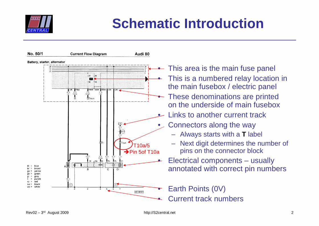
Schematic Introduction
• This area is the main fuse panel• This is a numbered relay location in
the main fusebox / electric panel• These denominations are printed
on the underside of main fusebox• Links to another current track• Connectors along the way
– Always starts with a T label– Next digit determines the number of
pins on the connector block
• Electrical components – usually annotated with correct pin numbers
• Earth Points (0V)• Current track numbers
T10a/5�Pin 5of T10a
2
http://S2central.netRev02 – 3rd August 2009
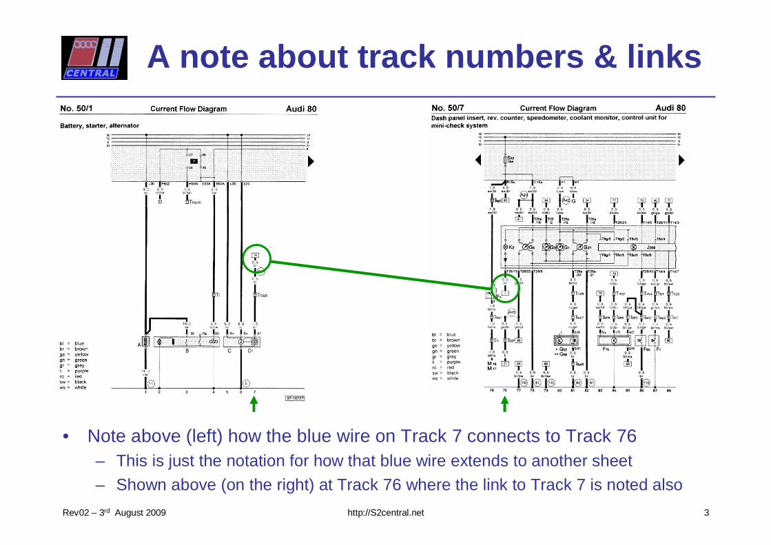
A note about track numbers & links
• Note above (left) how the blue wire on Track 7 connects to Track 76– This is just the notation for how that blue wire extends to another sheet
– Shown above (on the right) at Track 76 where the link to Track 7 is noted also
3
http://S2central.netRev02 – 3rd August 2009
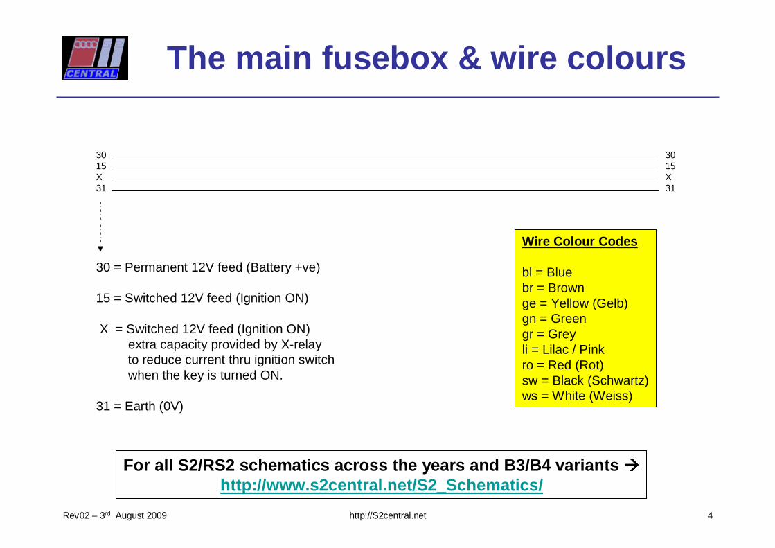
3015X31
3015X31
30 = Permanent 12V feed (Battery +ve)
15 = Switched 12V feed (Ignition ON)
X = Switched 12V feed (Ignition ON)extra capacity provided by X-relayto reduce current thru ignition switchwhen the key is turned ON.
31 = Earth (0V)
The main fusebox & wire colours
Wire Colour Codes
bl = Bluebr = Brownge = Yellow (Gelb)gn = Greengr = Greyli = Lilac / Pinkro = Red (Rot)sw = Black (Schwartz)ws = White (Weiss)
4
For all S2/RS2 schematics across the years and B3/B 4 variants ����http://www.s2central.net/S2_Schematics/
http://S2central.netRev02 – 3rd August 2009
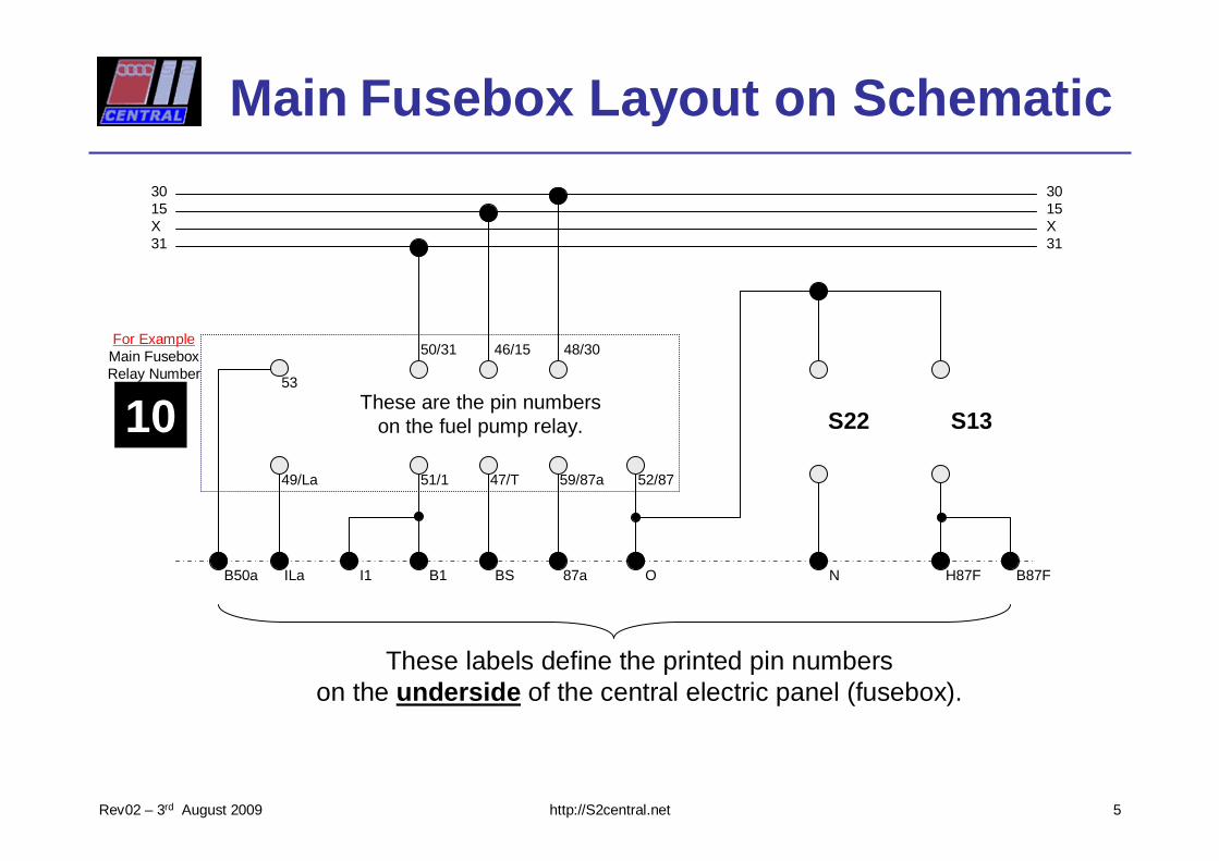
3015X31
3015X31
S22 S13
ILa I1 B1 BS 87a O N H87F B87F
49/La
53
51/1 47/T 59/87a 52/87
50/31 46/15 48/30
These labels define the printed pin numberson the underside of the central electric panel (fusebox).
These are the pin numberson the fuel pump relay.
Main Fusebox Layout on Schematic
10
For ExampleMain FuseboxRelay Number
B50a
5
http://S2central.netRev02 – 3rd August 2009
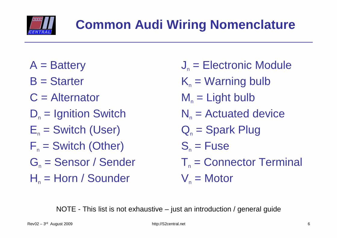
Common Audi Wiring Nomenclature
A = BatteryB = StarterC = AlternatorDn = Ignition SwitchEn = Switch (User)Fn = Switch (Other)Gn = Sensor / SenderHn = Horn / Sounder
Jn = Electronic Module Kn = Warning bulbMn = Light bulbNn = Actuated deviceQn = Spark PlugSn = FuseTn = Connector TerminalVn = Motor
6
NOTE - This list is not exhaustive – just an introduction / general guide
http://S2central.netRev02 – 3rd August 2009
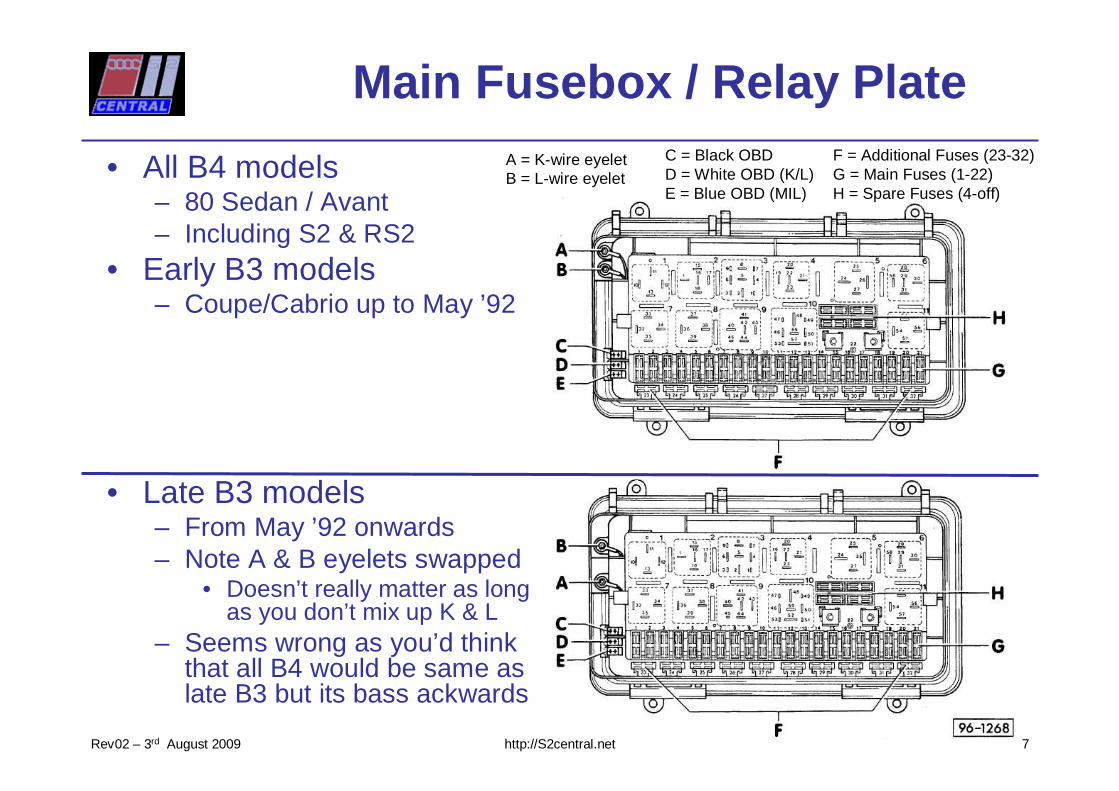
Main Fusebox / Relay Plate
• All B4 models– 80 Sedan / Avant– Including S2 & RS2
• Early B3 models– Coupe/Cabrio up to May ’92
• Late B3 models– From May ’92 onwards– Note A & B eyelets swapped
• Doesn’t really matter as long as you don’t mix up K & L
– Seems wrong as you’d think that all B4 would be same as late B3 but its bass ackwards
7
A = K-wire eyeletB = L-wire eyelet
C = Black OBDD = White OBD (K/L)E = Blue OBD (MIL)
F = Additional Fuses (23-32)G = Main Fuses (1-22)H = Spare Fuses (4-off)
http://S2central.netRev02 – 3rd August 2009
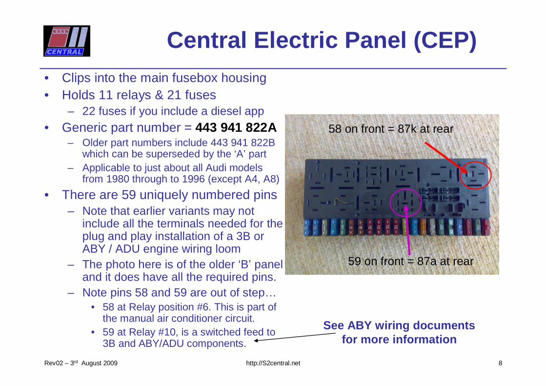
Central Electric Panel (CEP)• Clips into the main fusebox housing• Holds 11 relays & 21 fuses
– 22 fuses if you include a diesel app• Generic part number = 443 941 822A
– Older part numbers include 443 941 822B which can be superseded by the ‘A’ part
– Applicable to just about all Audi models from 1980 through to 1996 (except A4, A8)
• There are 59 uniquely numbered pins– Note that earlier variants may not
include all the terminals needed for the plug and play installation of a 3B or ABY / ADU engine wiring loom
– The photo here is of the older ‘B’ panel and it does have all the required pins.
– Note pins 58 and 59 are out of step…• 58 at Relay position #6. This is part of
the manual air conditioner circuit.• 59 at Relay #10, is a switched feed to
3B and ABY/ADU components.
59 on front = 87a at rear
58 on front = 87k at rear
8
See ABY wiring documentsfor more information
http://S2central.netRev02 – 3rd August 2009
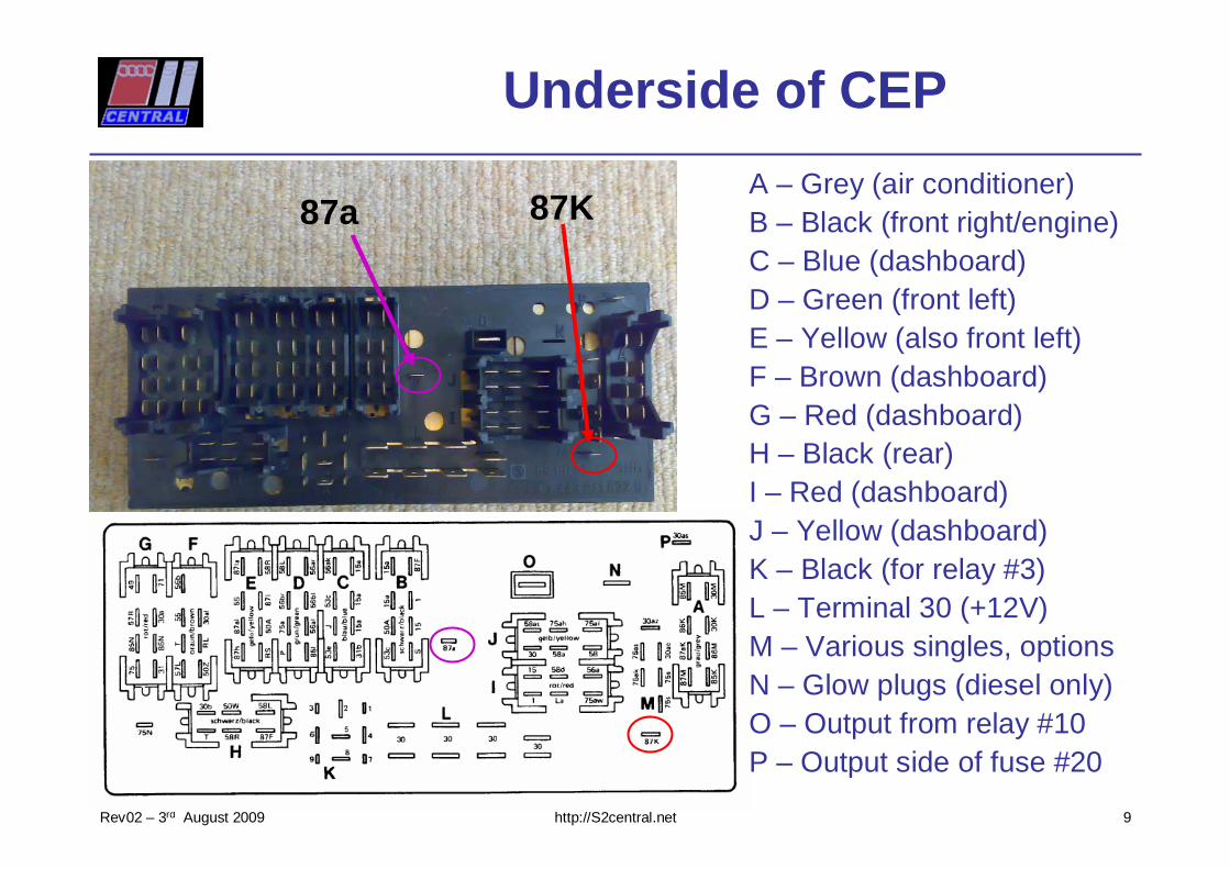
Underside of CEP
9
A – Grey (air conditioner)B – Black (front right/engine)C – Blue (dashboard)D – Green (front left)E – Yellow (also front left)F – Brown (dashboard)G – Red (dashboard)H – Black (rear)I – Red (dashboard)J – Yellow (dashboard)K – Black (for relay #3)L – Terminal 30 (+12V)M – Various singles, optionsN – Glow plugs (diesel only)O – Output from relay #10P – Output side of fuse #20
87a 87K
http://S2central.netRev02 – 3rd August 2009
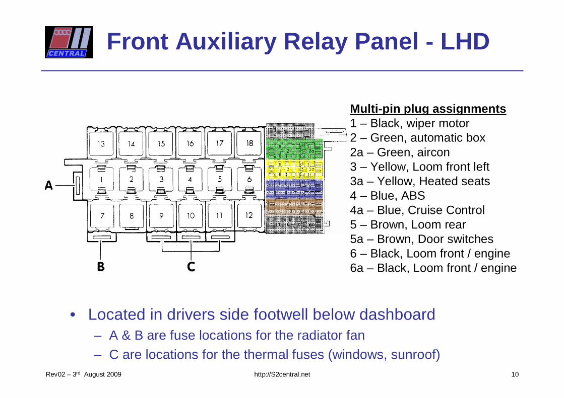
Front Auxiliary Relay Panel - LHD
• Located in drivers side footwell below dashboard– A & B are fuse locations for the radiator fan
– C are locations for the thermal fuses (windows, sunroof)10
Multi-pin plug assignments1 – Black, wiper motor2 – Green, automatic box2a – Green, aircon3 – Yellow, Loom front left3a – Yellow, Heated seats4 – Blue, ABS4a – Blue, Cruise Control 5 – Brown, Loom rear5a – Brown, Door switches6 – Black, Loom front / engine6a – Black, Loom front / engine
http://S2central.netRev02 – 3rd August 2009
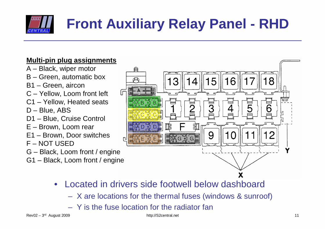
Front Auxiliary Relay Panel - RHD
• Located in drivers side footwell below dashboard– X are locations for the thermal fuses (windows & sunroof)– Y is the fuse location for the radiator fan
Multi-pin plug assignmentsA – Black, wiper motorB – Green, automatic boxB1 – Green, airconC – Yellow, Loom front leftC1 – Yellow, Heated seatsD – Blue, ABSD1 – Blue, Cruise Control E – Brown, Loom rearE1 – Brown, Door switchesF – NOT USEDG – Black, Loom front / engineG1 – Black, Loom front / engine
11
http://S2central.netRev02 – 3rd August 2009
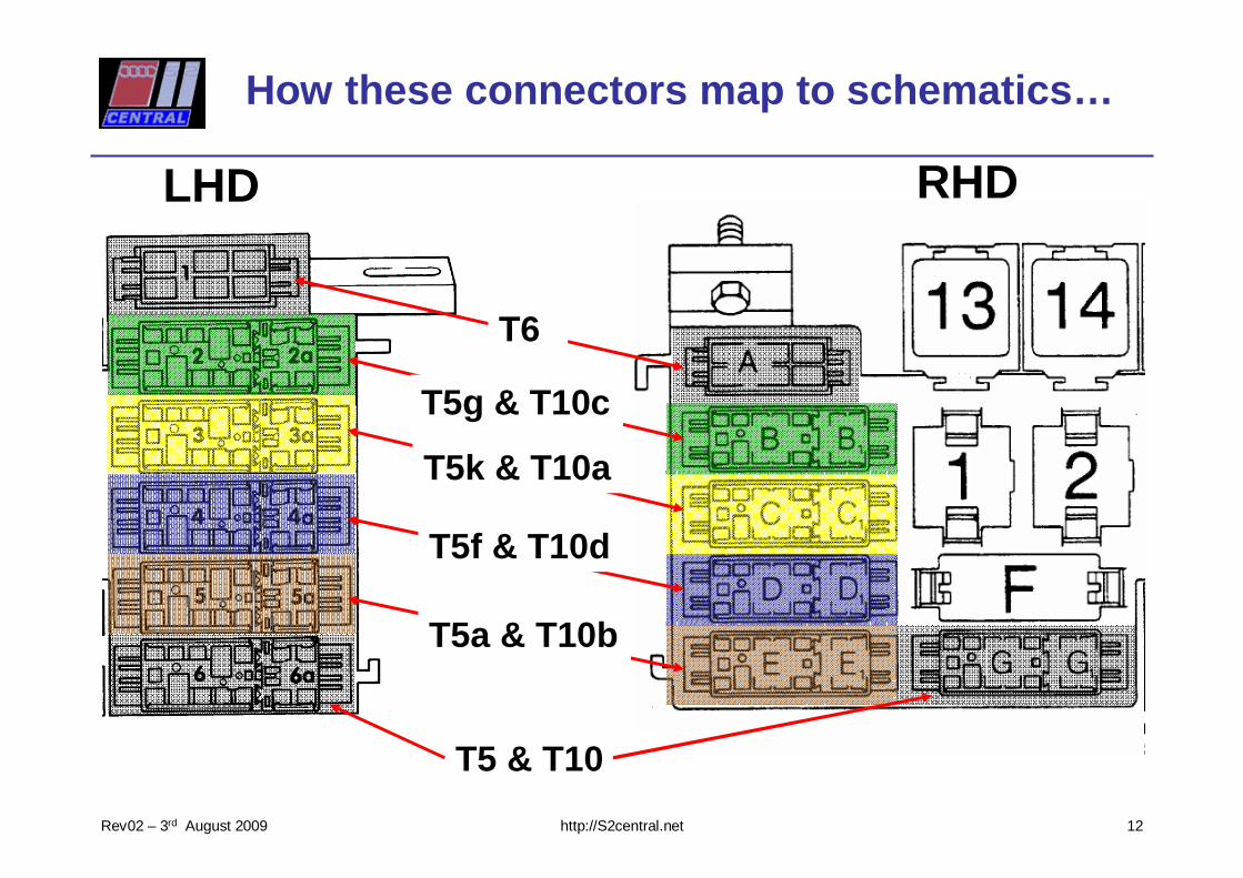
How these connectors map to schematics…
12
LHD RHD
T6
T5f & T10d
T5a & T10b
T5 & T10
T5g & T10c
T5k & T10a
http://S2central.netRev02 – 3rd August 2009
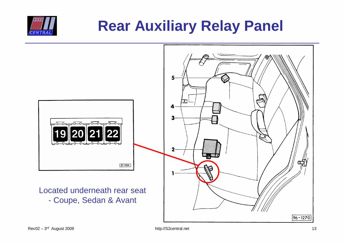
Rear Auxiliary Relay Panel
13
Located underneath rear seat- Coupe, Sedan & Avant
http://S2central.netRev02 – 3rd August 2009
END
Specific fuse and relay installationsare covered in another document.
Please send any comments, questions or corrections to
14