attachment e-7: oil spill prevention, control and countermeasure ( · pdf file ·...
TRANSCRIPT

LICENSE APPLICATION EXHIBIT E
Attachment E-7: Oil Spill Prevention, Control and
Countermeasure (SPCC) Plan
Boundary Hydroelectric Project Seattle City Light FERC No. 2144 September 2009

Seattle City Light
Oil Spill Prevention, Control andCountermeasure Plan
(SPCC Plan)
Boundary Powerhouse
(Revised February 17, 2006)
Prepared by:
Pam Hamlin
Seattle City LightGeneration Engineering Division
Becky Rufin, Acting Director


SPCC Plan, Boundary PowerhouseI:\pool\Civil\Pam\SPCC Plans\Generation\Boundary\2006Page i
Table of Contents
Page
Certification ............................................................................................. iii
Log of Updates and Amendments ......................................................... iiv
I. Purpose of the SPCC Plan ..................................................................... 1
II. General Information ................................................................................ 2
III. Summary of Compliance with 40 CFR 112.7 .......................................... 4
IV. What to do in the Event of an Oil Spill ................................................ 7
A. Notification Procedures ................................................................... 7
Spill Response Quick Reference ................................................ 10
B. Detailed Oil Spill Response Procedures ........................................ 11
C. When Oil Is Released to Water ...................................................... 11
D. Spill Kits ......................................................................................... 11
E. Methods of Disposal of Recovered Material (Spill Cleanup) .......... 11
V. Listing of Oil Storage Areas ................................................................... 12
1. Powerhouse.................................................................................... 142. Switchyard ..................................................................................... 213. Forebay .......................................................................................... 234. Oil House ....................................................................................... 255. Garage ........................................................................................... 276. Warehouse .................................................................................... 29
VI. Discharge Prevention Measures (Product Loading/Unloading) ............. 31
VII. Inspections, Tests, and Records............................................................. 32
VIII. Personnel Training for Discharge Prevention Procedures ..................... 33
SPCC Plan, Boundary PowerhouseI:\pool\Civil\Pam\SPCC Plans\Generation\Boundary\2006Page ii
IX. Security................................................................................................... 34
X. Recommendations ................................................................................. 35
XI. Appendices
Appendix "A" Facility Diagrams ............................................................ 37Appendix "B" Oil Containment System Capacity Calculations ............. 39Appendix "C" Hazardous Material Incident Report Form ..................... 40Appendix "D" Inspection Forms ........................................................... 42Appendix "E" Training Records ........................................................... 48Appendix "F" Certification of the "Substantial Harm Criteria" .............. 50Appendix "G" SCL Personnel List for Oil Spill Issues .......................... 51
Index ...................................................................................................... 52
SPCC Plan, Boundary PowerhouseI:\pool\Civil\Pam\SPCC Plans\Generation\Boundary\2006Page iv
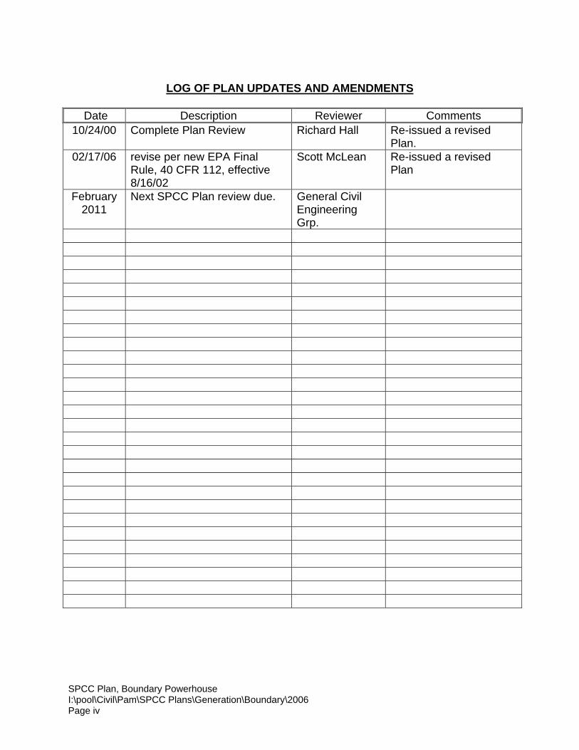
LOG OF PLAN UPDATES AND AMENDMENTS
Date Description Reviewer Comments10/24/00 Complete Plan Review Richard Hall Re-issued a revised
Plan.02/17/06 revise per new EPA Final
Rule, 40 CFR 112, effective8/16/02
Scott McLean Re-issued a revisedPlan
February2011
Next SPCC Plan review due. General CivilEngineeringGrp.
SPCC Plan, Boundary PowerhouseI:\pool\Civil\Pam\SPCC Plans\Generation\Boundary\2006Page 1
Spill Prevention, Control, and Countermeasure Plan (SPCC Plan)
BOUNDARY POWERHOUSE
I. PURPOSE OF THE SPCC PLAN
The purpose of this Spill Prevention, Control, Countermeasure Plan (SPCC) is to:
• Comply with the requirements of 40 CFR 112, which is the Federal regulationgoverning SPCC Plans;
• Document regulated oil storage quantities, locations and oil containmentmeasures/structures at the Boundary Powerhouse;
• Describe how oil spills at these locations could affect waters covered by the CleanWater Act;
• Set forth oil spill prevention and response procedures for the Boundary Powerhouse;
• Analyze the way oil is stored and used at this facility so as to insure adequate spillresponse procedures and spill containment to prevent oil spills and, moreimportantly, to prevent oil from entering navigable waters of the United States.
Roles and responsibilities in plan development and implementation:
• Responsibility for updating and certifying the SPCC Plan belongs to the GenerationEngineering Division. The Plan shall be reviewed every five (5) years and modified toinclude changes to the plan as they occur. Generation Engineering is responsiblefor determining whether current or future containment structures meet therequirements of 40 CFR 112.
• The Power Production Division is responsible for operating the BoundaryPowerhouse in compliance with this plan, and with the Clean Water Act. Thisincludes implementing the recommendations contained in Section X and ensuringthat workers are properly trained.
• The Environmental Affairs Division (EAD) will assist with regulatory requirements,and will conduct periodic audits of the Boundary to assess the adequacy of this plan.
SPCC Plan, Boundary PowerhouseI:\pool\Civil\Pam\SPCC Plans\Generation\Boundary\2006Page 2
II. GENERAL INFORMATION
A. Name and Address
Seattle City LightBoundary PowerhouseP.O. Box 219Metaline Falls, WA 99153
Note: this is the mailing address not the actual location.
B. Facility Covered by this SPCC Plan
This SPCC Plan covers the Seattle City Light Boundary Powerhouse on the PendOreille River in the State of Washington.
C. Features of the Boundary Powerhouse
The Boundary Powerhouse is located in the northeast corner of Washington on thePend Oreille River, 10 miles north of Metaline Falls and approximately 0.8 milessouth of the Canadian border. The Boundary Powerhouse is a 1,048-Mw capacityhydroelectric generating facility consisting of a thin concrete-arch dam, apowerhouse, and high voltage equipment located in a Bonneville PowerAdministration (BPA) switchyard. The dam is 340 feet high and 740 feet long at itscrest. The powerhouse is located downstream of the dam on the left bank and iscompletely underground. The BPA switchyard is approximately three-quarter milessouthwest of the powerhouse. A garage, an oil storage building, and a warehouseare located approximately one-half of a mile north of the powerhouse.
This 1,048-MW generating facility consists of the following major features;
• Dam
• Powerhouse and auxiliary buildings
• Switchyard transformers
D. Relationship to Waters of the United States
The Pend Oreille River flows north into Canada. The border is one miledownstream of Boundary Dam. The river flows through the Canadian Seven Mileand Waneta Dams, 10.5 and 17.5 miles downstream respectively from Boundary.The Pend Oreille River merges into the Columbia River just downstream of WanetaDam. The Columbia flows back into Washington and eventually empties into thePacific Ocean.
SPCC Plan, Boundary PowerhouseI:\pool\Civil\Pam\SPCC Plans\Generation\Boundary\2006Page 3
E. Responsibility for Oil Spill Prevention
The Power House Crew has the lead responsibility for oil spill prevention,containment, response and notification. The designated person accountable foroil spill prevention at the Boundary Powerhouse is:
Name: Lonnie Johnson
Telephone Numbers:Office: PAX 28-3214
(509) 446-3083Home: PAX 28-3248
(509) 442-4735Cell Phone: (509) 953-2037
F. Name and Address of Owner
City of SeattleCity Light Department700 5th Ave, Suite 3300P.O. Box 34023Seattle, WA 98124-4023
SPCC Plan, Boundary PowerhouseI:\pool\Civil\Pam\SPCC Plans\Generation\Boundary\2006Page 4
III. SUMMARY OF COMPLIANCE WITH 40 CFR 112.7
This Plan is prepared in accordance with 40 CFR 112.7, and follows the recommendedsequence. The following is a summary of the Plan components required by Sec. 112.7"General Requirements for Spill Prevention, Control, and Countermeasure Plans." Theparagraph numbers below are keyed to the paragraph numbers in 40 CFR 112.7, and across reference is provided for the corresponding parts of the Plan where applicable.
1. 40 CFR 112.7(a)(1). Discussion of The Facility's Conformance.
Generally, this facility is in conformance with the requirements of 40 CFR 112.Areas in which there are deficiencies that need to be corrected are summarized inSection X "Recommendations".
2. 40 CFR 112.7(a)(2). Compliance of this SPCC Plan with the requirements of 40CFR 112.
This Plan is in full compliance with the requirements of 40 CFR 112 as described inSec. 112.7(a)(2). There are no "equivalent environmental protection" or "alternate"methods employed.
3. 40 CFR 112.7(a)(3). Facility Diagrams.
For facility diagrams, see Appendix "A" of this Plan.
4. 40 CFR 112.7(a)(3). Transfer Stations and Connecting Pipes.
There is nothing at this facility of this type.
5. 40 CFR 112.7(a)(3)(i). Type of Oil and Storage Capacity.
This information is included in Section V "Listing of Oil Storage Areas"
6. 40 CFR 112.7(a)(3)(ii). Discharge Prevention Measures.
See Section VI "Discharge Prevention Measures (Product Loading/Unloading)"
7. 40 CFR 112.7(a)(3)(iii). Discharge or Drainage Controls (e.g. secondarycontainment)
This information is included in Section V of this Plan "Listing of Oil Storage Areas"
8. 40 CFR 112.7(a)(3)(iv). Countermeasures for Discharges (i.e. discovery, response,and cleanup)
See Section IV(B) "Oil Spill Response Procedures".
SPCC Plan, Boundary PowerhouseI:\pool\Civil\Pam\SPCC Plans\Generation\Boundary\2006Page 5
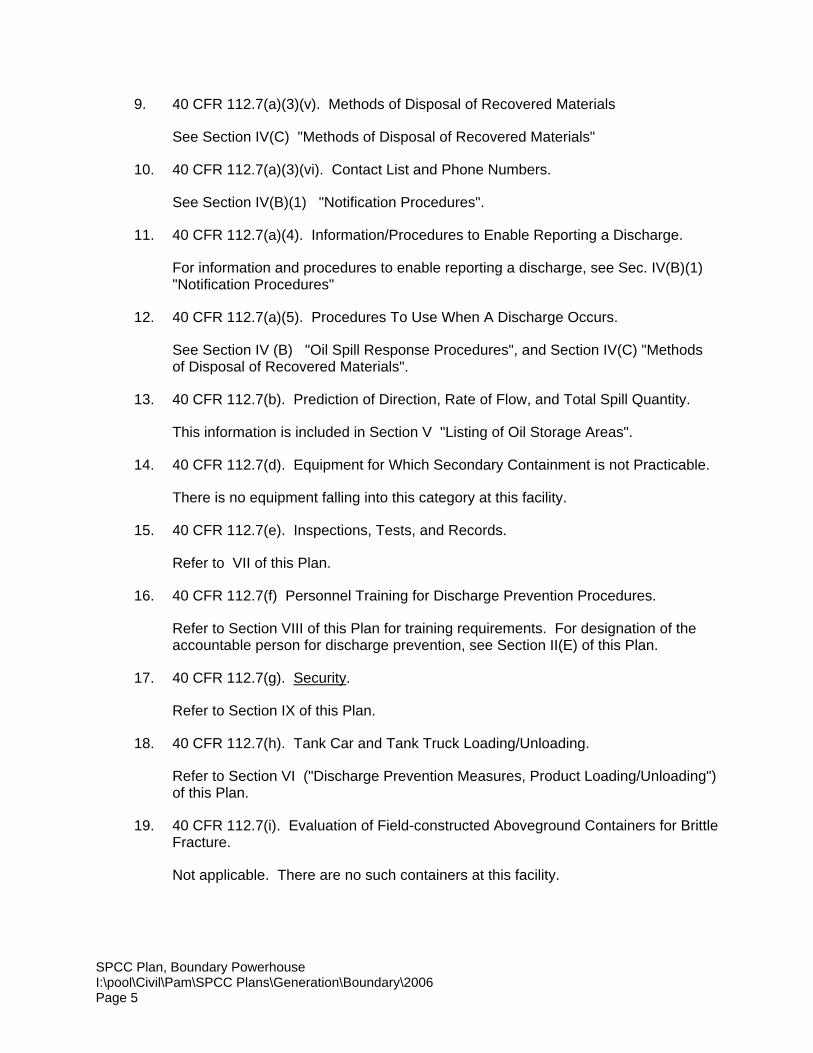
9. 40 CFR 112.7(a)(3)(v). Methods of Disposal of Recovered Materials
See Section IV(C) "Methods of Disposal of Recovered Materials"
10. 40 CFR 112.7(a)(3)(vi). Contact List and Phone Numbers.
See Section IV(B)(1) "Notification Procedures".
11. 40 CFR 112.7(a)(4). Information/Procedures to Enable Reporting a Discharge.
For information and procedures to enable reporting a discharge, see Sec. IV(B)(1)"Notification Procedures"
12. 40 CFR 112.7(a)(5). Procedures To Use When A Discharge Occurs.
See Section IV (B) "Oil Spill Response Procedures", and Section IV(C) "Methodsof Disposal of Recovered Materials".
13. 40 CFR 112.7(b). Prediction of Direction, Rate of Flow, and Total Spill Quantity.
This information is included in Section V "Listing of Oil Storage Areas".
14. 40 CFR 112.7(d). Equipment for Which Secondary Containment is not Practicable.
There is no equipment falling into this category at this facility.
15. 40 CFR 112.7(e). Inspections, Tests, and Records.
Refer to VII of this Plan.
16. 40 CFR 112.7(f) Personnel Training for Discharge Prevention Procedures.
Refer to Section VIII of this Plan for training requirements. For designation of theaccountable person for discharge prevention, see Section II(E) of this Plan.
17. 40 CFR 112.7(g). Security.
Refer to Section IX of this Plan.
18. 40 CFR 112.7(h). Tank Car and Tank Truck Loading/Unloading.
Refer to Section VI ("Discharge Prevention Measures, Product Loading/Unloading")of this Plan.
19. 40 CFR 112.7(i). Evaluation of Field-constructed Aboveground Containers for BrittleFracture.
Not applicable. There are no such containers at this facility.
SPCC Plan, Boundary PowerhouseI:\pool\Civil\Pam\SPCC Plans\Generation\Boundary\2006Page 6
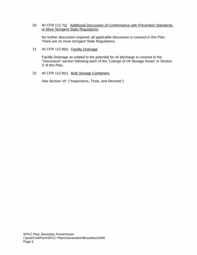
20. 40 CFR 112.7(j). Additional Discussion of Conformance with Prevention Standards,or More Stringent State Regulations.
No further discussion required; all applicable discussion is covered in this Plan.There are no more stringent State Regulations.
21. 40 CFR 112.8(b). Facility Drainage.
Facility Drainage as related to the potential for oil discharge is covered in the"Discussion" section following each of the "Listings of Oil Storage Areas" in SectionV of this Plan.
22. 40 CFR 112.8(c). Bulk Storage Containers.
See Section VII ("Inspections, Tests, and Records")
SPCC Plan, Boundary PowerhouseI:\pool\Civil\Pam\SPCC Plans\Generation\Boundary\2006Page 7
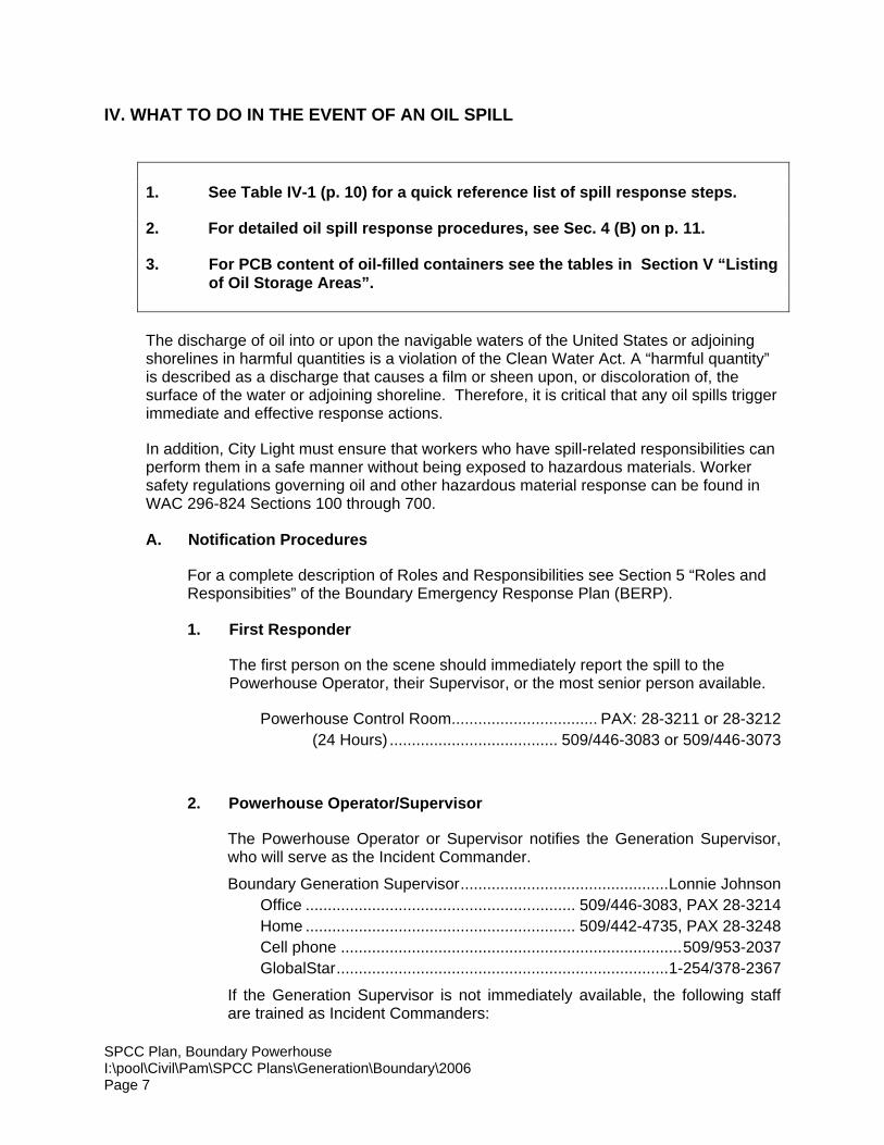
IV. WHAT TO DO IN THE EVENT OF AN OIL SPILL
1. See Table IV-1 (p. 10) for a quick reference list of spill response steps.
2. For detailed oil spill response procedures, see Sec. 4 (B) on p. 11.
3. For PCB content of oil-filled containers see the tables in Section V “Listingof Oil Storage Areas”.
The discharge of oil into or upon the navigable waters of the United States or adjoiningshorelines in harmful quantities is a violation of the Clean Water Act. A “harmful quantity”is described as a discharge that causes a film or sheen upon, or discoloration of, thesurface of the water or adjoining shoreline. Therefore, it is critical that any oil spills triggerimmediate and effective response actions.
In addition, City Light must ensure that workers who have spill-related responsibilities canperform them in a safe manner without being exposed to hazardous materials. Workersafety regulations governing oil and other hazardous material response can be found inWAC 296-824 Sections 100 through 700.
A. Notification Procedures
For a complete description of Roles and Responsibilities see Section 5 “Roles andResponsibities” of the Boundary Emergency Response Plan (BERP).
1. First Responder
The first person on the scene should immediately report the spill to thePowerhouse Operator, their Supervisor, or the most senior person available.
Powerhouse Control Room................................. PAX: 28-3211 or 28-3212(24 Hours) ...................................... 509/446-3083 or 509/446-3073
2. Powerhouse Operator/Supervisor
The Powerhouse Operator or Supervisor notifies the Generation Supervisor,who will serve as the Incident Commander.
Boundary Generation Supervisor...............................................Lonnie JohnsonOffice ............................................................. 509/446-3083, PAX 28-3214Home ............................................................. 509/442-4735, PAX 28-3248Cell phone .............................................................................509/953-2037GlobalStar...........................................................................1-254/378-2367
If the Generation Supervisor is not immediately available, the following staffare trained as Incident Commanders:

SPCC Plan, Boundary PowerhouseI:\pool\Civil\Pam\SPCC Plans\Generation\Boundary\2006Page 8
Wilhelm Botzheim, Office................................................................28-3216Home .........................................................................509/446-3943
Peggy Krabbenhoft, Office..............................................................28-3216Home .........................................................................509/446-2434
Todd McGregor, Office ...................................................................28-3216Home .........................................................................509/446-4402
Tim Pettis, Office ............................................................................28-3216Home .........................................................................509/442-3505
Rick Reiber, Office..........................................................................28-3216Home .........................................................................509/446-4195
Jeff Young, Office ...........................................................................28-3216Home .........................................................................509/442-3065
3. Incident Commander
If not previously notified, the Incident Commander notifies the System ControlCenter (SCC).
SCC Generation Dispatcher - Seattle line ....................................206/706-020424 hr. Service Dispatcher ......................................................206/706-0205Dispatcher (24 hr. South Desk) .............................................206/706-0201Dispatcher (24 hr. North Desk) ..............................................206/706-0202
The Incident Commander also does the following:• Decides whether immediate evacuation of a facility is necessary. If
yes, the Incident Commander alerts Project personnel and visitorsby:• Powerhouse: contacts the Powerhouse Operator to sound
the Powerhouse emergency alarm.• Maintenance Facilities: phone, radio, and/or door to door
communication. Assistance may be provided by the HazMatResponse Team.
• Notifies/designates the Boundary Hazardous Material IncidentResponse Team Leader
• Notifies the HazMat Response Team members, or instructs theResponse Team Leader to do so.
• If not previously notified, calls 911 (Pend Oreille County Sheriff’sOffice) if there are injuries or fire. Assigns someone to meet rescueworkers if 911 is called.

SPCC Plan, Boundary PowerhouseI:\pool\Civil\Pam\SPCC Plans\Generation\Boundary\2006Page 9
4. System Control Center/Incident Commander
Notifies Environmental Affairs, Environmental Management & Compliance Unit(EMC).
Work hours: ...........................................................................206/684-3270Off-hours:.................................................................. 206/995-2460 (pager)
5. Environmental Management and Compliance Unit
Notifies appropriate regulatory authorities. Notifies Emergency Response Contractor if needed. See Appendix II
of the BERP.
SPCC Plan, Boundary PowerhouseI:\pool\Civil\Pam\SPCC Plans\Generation\Boundary\2006Page 10
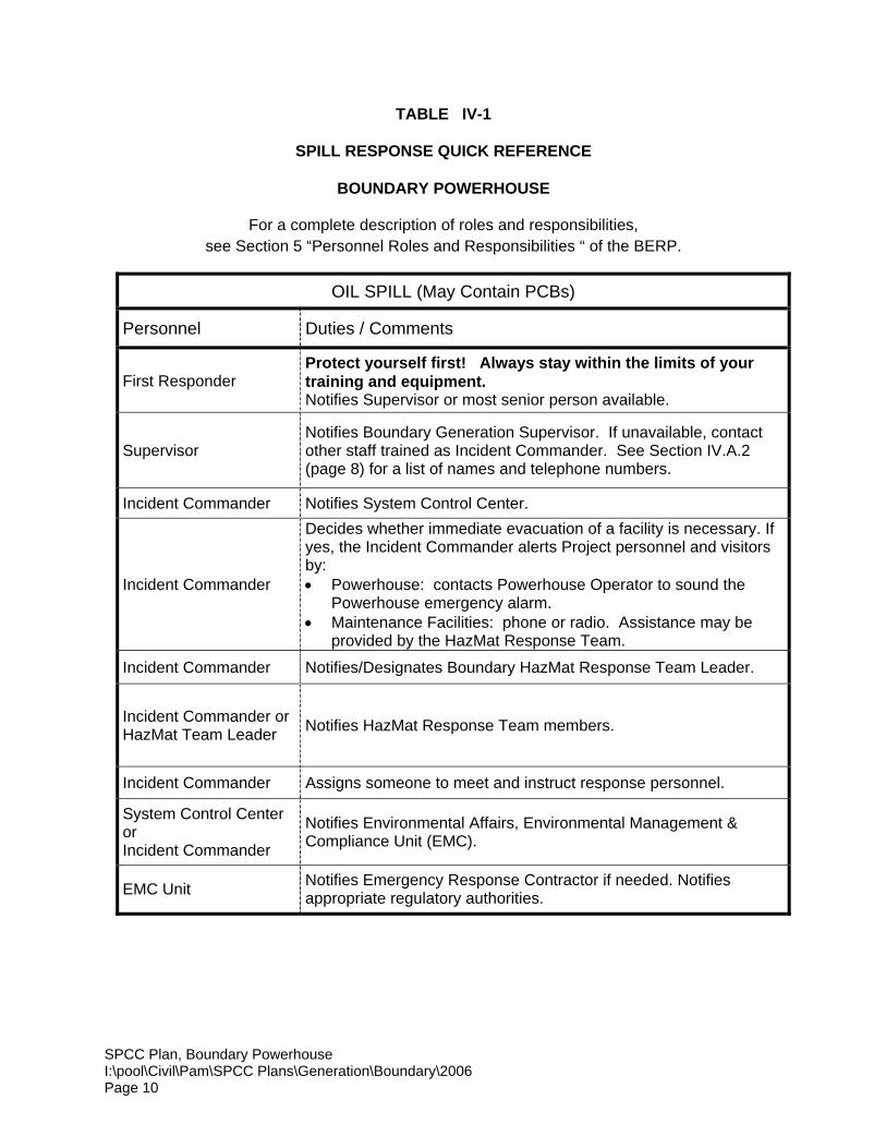
TABLE IV-1
SPILL RESPONSE QUICK REFERENCE
BOUNDARY POWERHOUSE
For a complete description of roles and responsibilities,see Section 5 “Personnel Roles and Responsibilities “ of the BERP.
OIL SPILL (May Contain PCBs)
Personnel Duties / Comments
First ResponderProtect yourself first! Always stay within the limits of yourtraining and equipment.Notifies Supervisor or most senior person available.
SupervisorNotifies Boundary Generation Supervisor. If unavailable, contactother staff trained as Incident Commander. See Section IV.A.2(page 8) for a list of names and telephone numbers.
Incident Commander Notifies System Control Center.
Incident Commander
Decides whether immediate evacuation of a facility is necessary. Ifyes, the Incident Commander alerts Project personnel and visitorsby:• Powerhouse: contacts Powerhouse Operator to sound the
Powerhouse emergency alarm.• Maintenance Facilities: phone or radio. Assistance may be
provided by the HazMat Response Team.
Incident Commander Notifies/Designates Boundary HazMat Response Team Leader.
Incident Commander orHazMat Team Leader Notifies HazMat Response Team members.
Incident Commander Assigns someone to meet and instruct response personnel.
System Control CenterorIncident Commander
Notifies Environmental Affairs, Environmental Management &Compliance Unit (EMC).
EMC Unit Notifies Emergency Response Contractor if needed. Notifiesappropriate regulatory authorities.
SPCC Plan, Boundary PowerhouseI:\pool\Civil\Pam\SPCC Plans\Generation\Boundary\2006Page 11
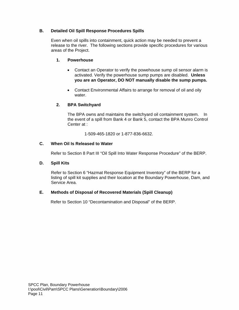
B. Detailed Oil Spill Response Procedures Spills
Even when oil spills into containment, quick action may be needed to prevent arelease to the river. The following sections provide specific procedures for variousareas of the Project.
1. Powerhouse
• Contact an Operator to verify the powehouse sump oil sensor alarm isactivated. Verify the powerhouse sump pumps are disabled. Unlessyou are an Operator, DO NOT manually disable the sump pumps.
• Contact Environmental Affairs to arrange for removal of oil and oilywater.
2. BPA Switchyard
The BPA owns and maintains the switchyard oil containment system. Inthe event of a spill from Bank 4 or Bank 5, contact the BPA Munro ControlCenter at :
1-509-465-1820 or 1-877-836-6632.
C. When Oil Is Released to Water
Refer to Section 8 Part III “Oil Spill Into Water Response Procedure” of the BERP.
D. Spill Kits
Refer to Section 6 “Hazmat Response Equipment Inventory” of the BERP for alisting of spill kit supplies and their location at the Boundary Powerhouse, Dam, andService Area.
E. Methods of Disposal of Recovered Materials (Spill Cleanup)
Refer to Section 10 “Decontamination and Disposal” of the BERP.
SPCC Plan, Boundary PowerhouseI:\pool\Civil\Pam\SPCC Plans\Generation\Boundary\2006Page 12
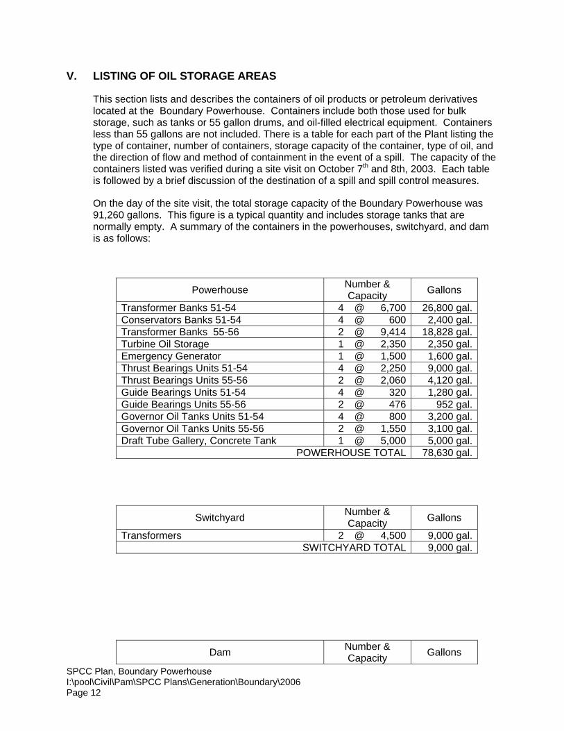
V. LISTING OF OIL STORAGE AREAS
This section lists and describes the containers of oil products or petroleum derivativeslocated at the Boundary Powerhouse. Containers include both those used for bulkstorage, such as tanks or 55 gallon drums, and oil-filled electrical equipment. Containersless than 55 gallons are not included. There is a table for each part of the Plant listing thetype of container, number of containers, storage capacity of the container, type of oil, andthe direction of flow and method of containment in the event of a spill. The capacity of thecontainers listed was verified during a site visit on October 7th and 8th, 2003. Each tableis followed by a brief discussion of the destination of a spill and spill control measures.
On the day of the site visit, the total storage capacity of the Boundary Powerhouse was91,260 gallons. This figure is a typical quantity and includes storage tanks that arenormally empty. A summary of the containers in the powerhouses, switchyard, and damis as follows:
Powerhouse Number &Capacity Gallons
Transformer Banks 51-54 4 @ 6,700 26,800 gal.Conservators Banks 51-54 4 @ 600 2,400 gal.Transformer Banks 55-56 2 @ 9,414 18,828 gal.Turbine Oil Storage 1 @ 2,350 2,350 gal.Emergency Generator 1 @ 1,500 1,600 gal.Thrust Bearings Units 51-54 4 @ 2,250 9,000 gal.Thrust Bearings Units 55-56 2 @ 2,060 4,120 gal.Guide Bearings Units 51-54 4 @ 320 1,280 gal.Guide Bearings Units 55-56 2 @ 476 952 gal.Governor Oil Tanks Units 51-54 4 @ 800 3,200 gal.Governor Oil Tanks Units 55-56 2 @ 1,550 3,100 gal.Draft Tube Gallery, Concrete Tank 1 @ 5,000 5,000 gal.
POWERHOUSE TOTAL 78,630 gal.
Switchyard Number &Capacity Gallons
Transformers 2 @ 4,500 9,000 gal.SWITCHYARD TOTAL 9,000 gal.
Dam Number &Capacity Gallons
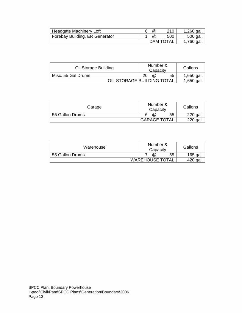
SPCC Plan, Boundary PowerhouseI:\pool\Civil\Pam\SPCC Plans\Generation\Boundary\2006Page 13
Headgate Machinery Loft 6 @ 210 1,260 gal.Forebay Building, ER Generator 1 @ 500 500 gal.
DAM TOTAL 1,760 gal.
Oil Storage Building Number &Capacity Gallons
Misc. 55 Gal Drums 20 @ 55 1,650 gal.OIL STORAGE BUILDING TOTAL 1,650 gal.
Garage Number &Capacity Gallons
55 Gallon Drums 6 @ 55 220 gal.GARAGE TOTAL 220 gal.
Warehouse Number &Capacity Gallons
55 Gallon Drums 7 @ 55 165 gal.WAREHOUSE TOTAL 420 gal.
SPCC Plan, Boundary PowerhouseI:\pool\Civil\Pam\SPCC Plans\Generation\Boundary\2006Page 14
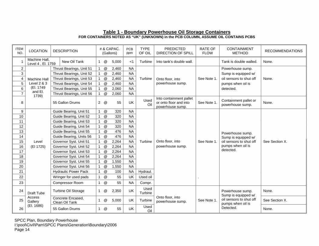
Table 1 - Boundary Powerhouse Oil Storage ContainersFOR CONTAINERS NOTED AS “UK” (UNKNOWN) in the PCB COLUMN, ASSUME OIL CONTAINS PCBS
ITEMNO. LOCATION DESCRIPTION # & CAPAC.
(Gallons)PCBppm
TYPEOF OIL
PREDICTEDDIRECTION OF SPILL
RATE OFFLOW
CONTAINMENTMETHOD RECOMMENDATIONS
1 Machine Hall,Level 4 , El. 1759 New Oil Tank 1 @ 5,000 <1 Turbine Into tank’s double wall. Tank is double walled. None.
2 Thrust Bearings, Unit 51 1 @ 2,460 NA Powerhouse sump.3 Thrust Bearings, Unit 52 1 @ 2,460 NA Sump is equipped w/4 Thrust Bearings, Unit 53 1 @ 2,460 NA Turbine See Note 1. oil sensors to shut off None.5 Thrust Bearings, Unit 54 1 @ 2,460 NA pumps when oil is6 Thrust Bearings, Unit 55 1 @ 2,060 NA detected.7 Thrust Bearings, Unit 56 1 @ 2,060 NA
Onto floor, intopowerhouse sump.
8
Machine HallLevel 2 & 3(El. 1749and El.1739)
55 Gallon Drums 2 @ 55 UK UsedOil
Into containment palletor onto floor and intopowerhouse sump.
See Note 1. Containment pallet orpowerhouse sump. None.
9 Guide Bearing, Unit 51 1 @ 320 NA10 Guide Bearing, Unit 52 1 @ 320 NA11 Guide Bearing, Unit 53 1 @ 320 NA12 Guide Bearing, Unit 54 1 @ 320 NA13 Guide Bearing, Unit 55 1 @ 476 NA14 Guide Bearing, Units 56 1 @ 476 NA15 Level Governor Syst. Unit 51 1 @ 2,264 NA Turbine Onto floor, into See Note 1. See Section X.16 (El 1725) Governor Syst. Unit 52 1 @ 2,264 NA powerhouse sump.17 Governor Syst. Unit 53 1 @ 2,264 NA
Powerhouse sump.Sump is equipped w/oil sensors to shut offpumps when oil isdetected.
18 Governor Syst. Unit 54 1 @ 2,264 NA19 Governor Syst. Unit 55 1 @ 1,550 NA20 Governor Syst. Unit 56 1 @ 1,550 NA21 Hydraulic Power Pack 1 @ 100 NA Hydraul.22 Wringer for used pads 1 @ 55 UK Used oil .23 Compressor Room 1 @ 55 NA Compr.
24 Turbine Oil Storage 1 @ 2,350 UK UsedTurbine None.
25 Concrete Encased,Clean Oil Tank 1 @ 5,000 UK Turbine See Note 1. See Section X.
26
Draft TubeAccessGallery(El. 1686)
55 Gallon Drums 1 @ 55 UK UsedOil
Onto floor, intopowerhouse sump.
Powerhouse sump.Sump is equipped w/oil sensors to shut offpumps when oil isDetected. None.
SPCC Plan, Boundary PowerhouseI:\pool\Civil\Pam\SPCC Plans\Generation\Boundary\2006Page 15
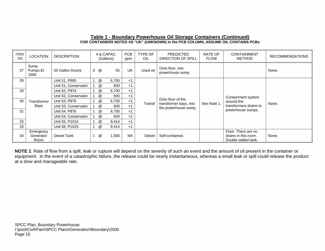
Table 1 - Boundary Powerhouse Oil Storage Containers (Continued)FOR CONTAINERS NOTED AS “UK” (UNKNOWN) in the PCB COLUMN, ASSUME OIL CONTAINS PCBs
ITEMNO. LOCATION DESCRIPTION # & CAPAC.
(Gallons)PCBppm
TYPE OFOIL
PREDICTEDDIRECTION OF SPILL
RATE OFFLOW
CONTAINMENTMETHOD RECOMMENDATIONS
27SumpPumps El.1666
55 Gallon Drums 3 @ 55 UK Used oil Onto floor, intopowerhouse sump None.
28 Unit 51, P900 1 @ 6,700 <1Unit 51, Conservator 1 @ 600 <1
29 Unit 52, P874 1 @ 6,700 <1Unit 52, Conservator 1 @ 600 <1
30 Unit 53, P875 1 @ 6,700 <1Unit 53, Conservator 1 @ 600 <1
31 Unit 54, P876 1 @ 6,700 <1Unit 54, Conservator 1 @ 600 <1
32 Unit 55, P1014 1 @ 9,414 <133
TransformerBays
Unit 56, P1015 1 @ 9,414 <1
TransilOnto floor of thetransformer bays, intothe powerhouse sump.
See Note 1.
Containment systemaround thetransformers drains topowerhouse sumps.
None.
34EmergencyGenerator
RoomDiesel Tank 1 @ 1,500 NA Diesel Self-contained.
Floor. There are nodrains in this room.Double walled tank.
None.
NOTE 1: Rate of flow from a spill, leak or rupture will depend on the severity of such an event and the amount of oil present in the container orequipment. In the event of a catastrophic failure, the release could be nearly instantaneous, whereas a small leak or spill could release the productat a slow and manageable rate.
SPCC Plan, Boundary PowerhouseI:\pool\Civil\Pam\SPCC Plans\Generation\Boundary\2006Page 16
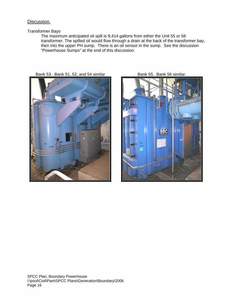
Discussion.
Transformer BaysThe maximum anticipated oil spill is 9,414 gallons from either the Unit 55 or 56transformer. The spilled oil would flow through a drain at the back of the transformer bay,then into the upper PH sump. There is an oil sensor in the sump. See the discussion“Powerhouse Sumps” at the end of this discussion.
Bank 53. Bank 51, 52, and 54 similar Bank 55. Bank 56 similar.

SPCC Plan, Boundary PowerhouseI:\pool\Civil\Pam\SPCC Plans\Generation\Boundary\2006Page 17
Emergency Generator RoomThe maximum anticipated oil spill is 1,500 gallons of diesel oil from the generator. Thetank is double-walled, so any leak in the tank should be contained within the tank. Thereare no drains in the generator room.
Level 4, Machine Hall (Elev. 1759)The maximum anticipated oil spill is 5,000 gallons from the new oil tank located nearUnit 56. The oil would flow onto the floor that drains to the upper sump.
New Oil Tank, Level 4
Level 2 (Elev. 1739 and Elev. 1749)

SPCC Plan, Boundary PowerhouseI:\pool\Civil\Pam\SPCC Plans\Generation\Boundary\2006Page 18
The maximum anticipated oil spill is 2,250 gallons of turbine oil from the thrust bearingsof either Unit 51, 52, 53 or 54. The oil would flow onto the floor that drains to the uppersump.
Level 1 (Elev. 1725)The maximum anticipated oil spill is 1,550 gallons from either the Unit 55 or 56 governorsystem. The oil would flow onto the floor that drains to the upper sump.
Governor Tanks, Unit 55
Draft Tube Access Gallery (Elev. 1686’)The maximum anticipated oil spill is 5,000 gallons from the concrete encased,clean oil tank. A spill would drain into the lower powerhouse sump.
Face oftank

SPCC Plan, Boundary PowerhouseI:\pool\Civil\Pam\SPCC Plans\Generation\Boundary\2006Page 19
Powerhouse Sump Oil Containment System
Upper Sump (Reference Drawing No. D-23458)The upper sump has two pumps. Under normal operation the two pumps are used tocontrol the liquid level in the sump. There is an oil sensor in the sump that disables thepumps when oil is detected. The sump will then overflow to the lower sump. At worst casethere is 2 feet of free board from the top of the operating limit (El. 1701) to the overflow (tothe lower sump) at El. 1703. This equates to 2,543 gallons of storage capacity. There is nooil skimmer in the upper sump.
Pumps at Upper Sump
Lower Sump (Reference Drawing No. D-23459)There are 7 pumps in the lower sump. The sump is equipped with an oil sensor that willeither activate the oil skimmer (2 mm oil thickness), or if the sensor detects a thick enoughlayer of oil (5 mm) the pump operating sequence will change. In the latter case the alarmsecures all 7 pumps and resets operating levels. Pumps 1 and 3 have the lowest suctionlevel. Initially only pumps 1 or 3 will operate with the stop/start elevations resetting from1645/1649 to 1649/1652 after the 5 mm alarm. If the liquid level continues to rise, pumps 4and 5 will begin operation at elevation 1657. Pumps 4 and 5 are located the farthest fromthe inlet to the dewatering section of the lower sump. At elevation 1658 all pumps willoperate regardless of the oil alarm condition.
In the worst case should an oil spill occur when pumps 1 and 3 are ready to cut in (El 1649normal condition), then there will be an additional 3 feet of sump available before the pumpsbegin again. Between these elevations (1649 to 1652) the sump is connected to thedrainage gallery such that there is an additional storage capacity gained of 25,622 gallonsfor a total of 39,183 gallons available. Normal water inflow into this sump from drains andmachinery leaks is 300 gpm.
SPCC Plan, Boundary PowerhouseI:\pool\Civil\Pam\SPCC Plans\Generation\Boundary\2006Page 20
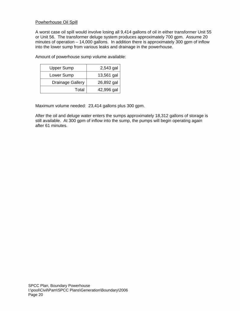
Powherhouse Oil Spill
A worst case oil spill would involve losing all 9,414 gallons of oil in either transformer Unit 55or Unit 56. The transformer deluge system produces approximately 700 gpm. Assume 20minutes of operation – 14,000 gallons. In addition there is approximately 300 gpm of inflowinto the lower sump from various leaks and drainage in the powerhouse.
Amount of powerhouse sump volume available:
Upper Sump 2,543 gal
Lower Sump 13,561 gal
Drainage Gallery 26,892 gal
Total 42,996 gal
Maximum volume needed: 23,414 gallons plus 300 gpm.
After the oil and deluge water enters the sumps approximately 18,312 gallons of storage isstill available. At 300 gpm of inflow into the sump, the pumps will begin operating againafter 61 minutes.
SPCC Plan, Boundary PowerhouseI:\pool\Civil\Pam\SPCC Plans\Generation\Boundary\2006Page 21
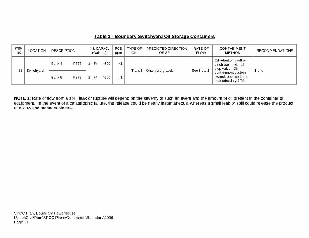
Table 2 - Boundary Switchyard Oil Storage Containers
ITEMNO. LOCATION DESCRIPTION # & CAPAC.
(Gallons)PCBppm
TYPE OFOIL
PREDICTED DIRECTIONOF SPILL
RATE OFFLOW
CONTAINMENTMETHOD RECOMMENDATIONS
Bank 4 P873 1 @ 4500 <1
35 Switchyard
Bank 5 P872 1 @ 4500 <1
Transil Onto yard gravel. See Note 1.
Oil retention vault orcatch basin with oilstop valve. Oilcontainment systemowned, operated, andmaintained by BPA.
None.
NOTE 1: Rate of flow from a spill, leak or rupture will depend on the severity of such an event and the amount of oil present in the container orequipment. In the event of a catastrophic failure, the release could be nearly instantaneous, whereas a small leak or spill could release the productat a slow and manageable rate.
SPCC Plan, Boundary PowerhouseI:\pool\Civil\Pam\SPCC Plans\Generation\Boundary\2006Page 22
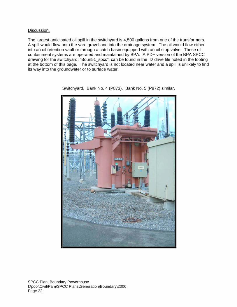
Discussion.
The largest anticipated oil spill in the switchyard is 4,500 gallons from one of the transformers.A spill would flow onto the yard gravel and into the drainage system. The oil would flow eitherinto an oil retention vault or through a catch basin equipped with an oil stop valve. These oilcontainment systems are operated and maintained by BPA. A PDF version of the BPA SPCCdrawing for the switchyard, “Boun51_spcc”, can be found in the I:\ drive file noted in the footingat the bottom of this page. The switchyard is not located near water and a spill is unlikely to findits way into the groundwater or to surface water.
Switchyard. Bank No. 4 (P873). Bank No. 5 (P872) similar.
SPCC Plan, Boundary PowerhouseI:\pool\Civil\Pam\SPCC Plans\Generation\Boundary\2006Page 23
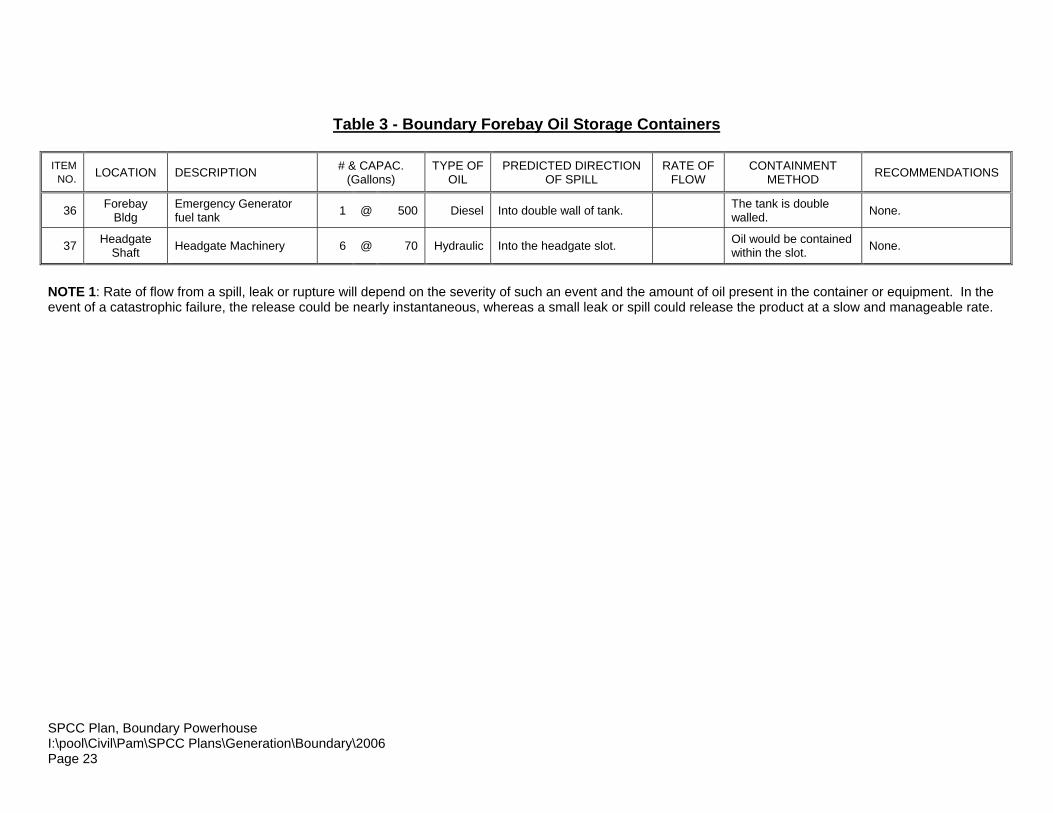
Table 3 - Boundary Forebay Oil Storage Containers
ITEMNO. LOCATION DESCRIPTION # & CAPAC.
(Gallons)TYPE OF
OILPREDICTED DIRECTION
OF SPILLRATE OF
FLOWCONTAINMENT
METHOD RECOMMENDATIONS
36 ForebayBldg
Emergency Generatorfuel tank 1 @ 500 Diesel Into double wall of tank. The tank is double
walled. None.
37 HeadgateShaft Headgate Machinery 6 @ 70 Hydraulic Into the headgate slot. Oil would be contained
within the slot. None.
NOTE 1: Rate of flow from a spill, leak or rupture will depend on the severity of such an event and the amount of oil present in the container or equipment. In theevent of a catastrophic failure, the release could be nearly instantaneous, whereas a small leak or spill could release the product at a slow and manageable rate.
SPCC Plan, Boundary PowerhouseI:\pool\Civil\Pam\SPCC Plans\Generation\Boundary\2006Page 24
Headgate Machinery
The headgate machinery consists of several pieces of equipment. The largest anticipated spillfrom this equipment is approximately 70 gallons of hydraulic fluid from the retarder. Dischargefrom this equipment is directed into the headgate slots. Because of the arrangement of theheadgate slots, any oil that spills into this area would be contained there until it is cleaned up.The headgates are inspected regularly, and any oil on the water surface in the slot would bedetected quickly.
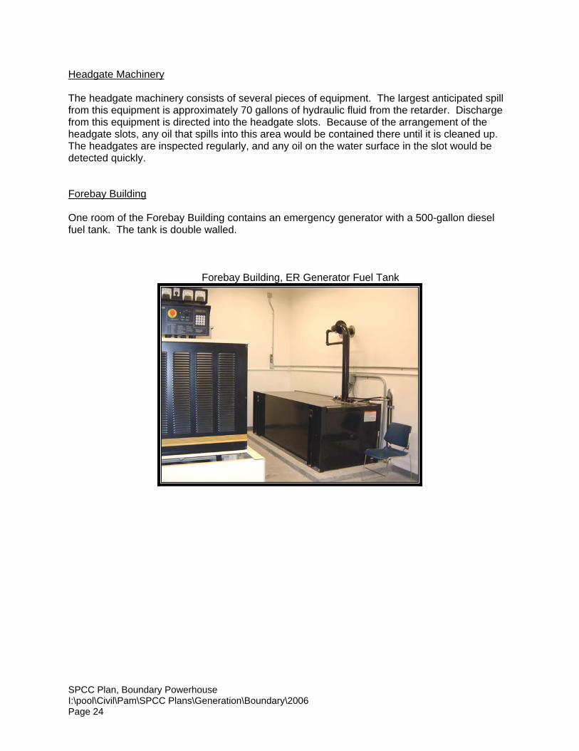
Forebay Building
One room of the Forebay Building contains an emergency generator with a 500-gallon dieselfuel tank. The tank is double walled.
Forebay Building, ER Generator Fuel Tank
SPCC Plan, Boundary PowerhouseI:\pool\Civil\Pam\SPCC Plans\Generation\Boundary\2006Page 25
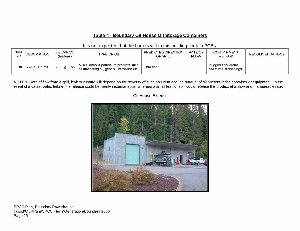
Table 4 - Boundary Oil House Oil Storage Containers
It is not expected that the barrels within this building contain PCBs.ITEM
NO. DESCRIPTION # & CAPAC.(Gallons) TYPE OF OIL PREDICTED DIRECTION
OF SPILLRATE OF
FLOWCONTAINMENT
METHOD RECOMMENDATIONS
38 55-Gal. Drums 20 @ 55 Miscellaneous petroleum products suchas lubricating oil, gear oil, kerosene etc. Onto floor. Plugged floor drains
and curbs at openings.
NOTE 1: Rate of flow from a spill, leak or rupture will depend on the severity of such an event and the amount of oil present in the container or equipment. In theevent of a catastrophic failure, the release could be nearly instantaneous, whereas a small leak or spill could release the product at a slow and manageable rate.
Oil House Exterior
SPCC Plan, Boundary PowerhouseI:\pool\Civil\Pam\SPCC Plans\Generation\Boundary\2006Page 26
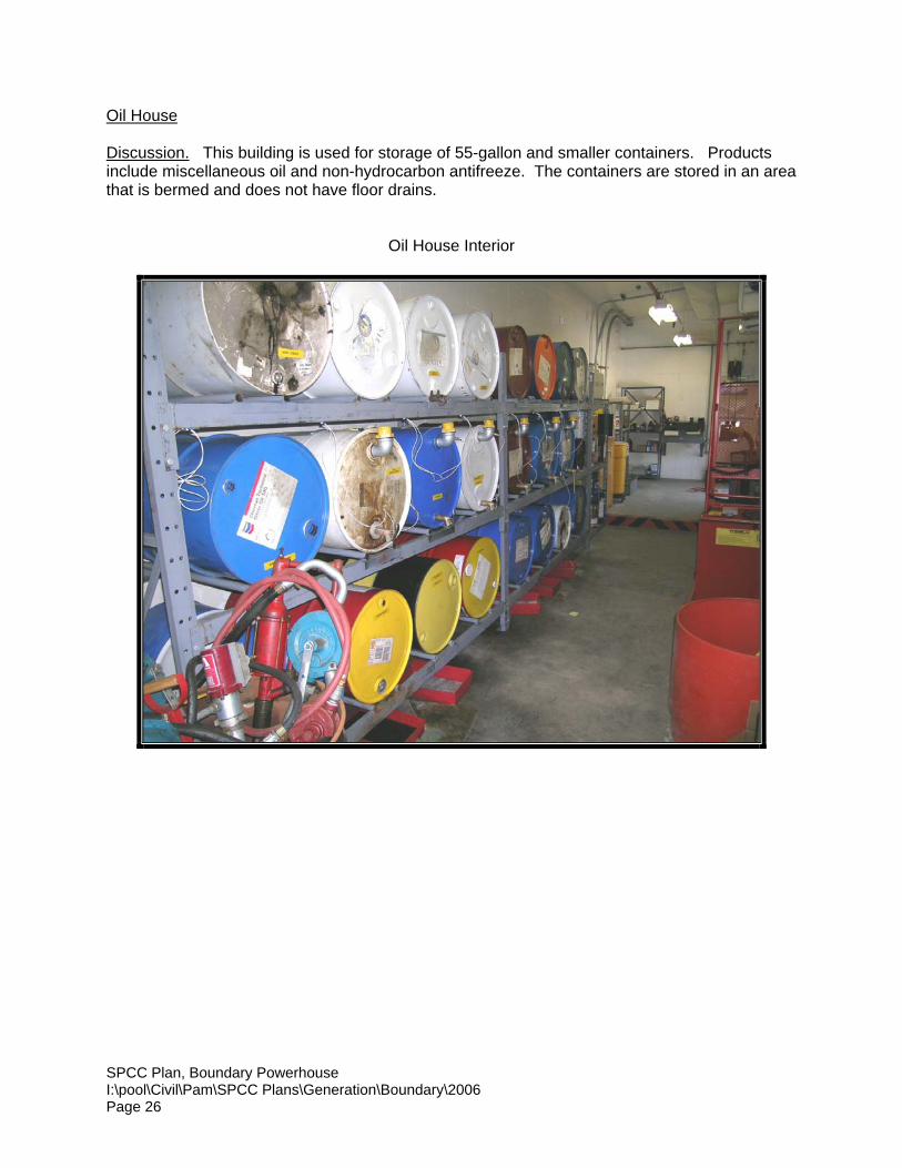
Oil House
Discussion. This building is used for storage of 55-gallon and smaller containers. Productsinclude miscellaneous oil and non-hydrocarbon antifreeze. The containers are stored in an areathat is bermed and does not have floor drains.
Oil House Interior
SPCC Plan, Boundary PowerhouseI:\pool\Civil\Pam\SPCC Plans\Generation\Boundary\2006Page 27
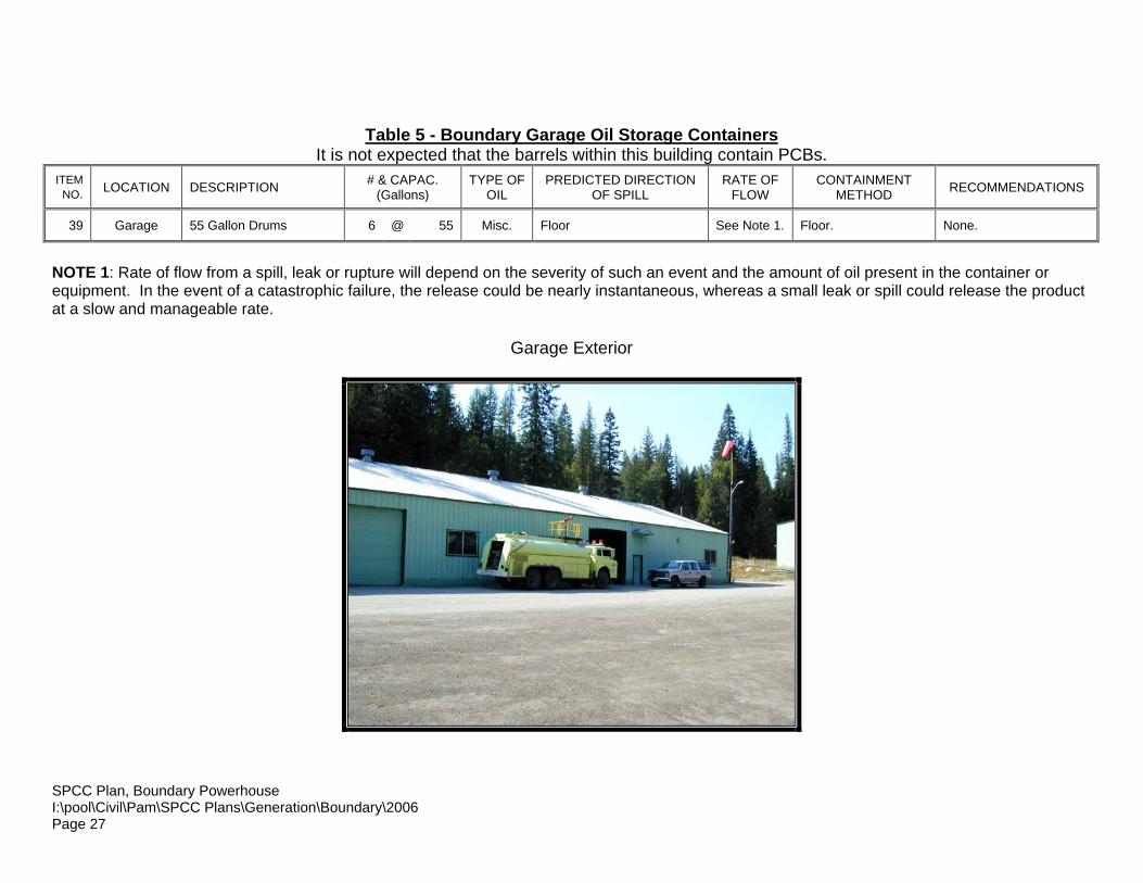
Table 5 - Boundary Garage Oil Storage ContainersIt is not expected that the barrels within this building contain PCBs.
ITEMNO. LOCATION DESCRIPTION # & CAPAC.
(Gallons)TYPE OF
OILPREDICTED DIRECTION
OF SPILLRATE OF
FLOWCONTAINMENT
METHOD RECOMMENDATIONS
39 Garage 55 Gallon Drums 6 @ 55 Misc. Floor See Note 1. Floor. None.
NOTE 1: Rate of flow from a spill, leak or rupture will depend on the severity of such an event and the amount of oil present in the container orequipment. In the event of a catastrophic failure, the release could be nearly instantaneous, whereas a small leak or spill could release the productat a slow and manageable rate.
Garage Exterior

SPCC Plan, Boundary PowerhouseI:\pool\Civil\Pam\SPCC Plans\Generation\Boundary\2006Page 28
Garage
Discussion.. The anticipated maximum spill is one 55-gallon drum. The drums are seated oncontainment pallets. If a drum tipped over a spill would spread across the floor. It is possible,but unlikely that a spill could spread across the floor and out the door into the storm waterdrainage system.
Garage Interior
SPCC Plan, Boundary PowerhouseI:\pool\Civil\Pam\SPCC Plans\Generation\Boundary\2006Page 29
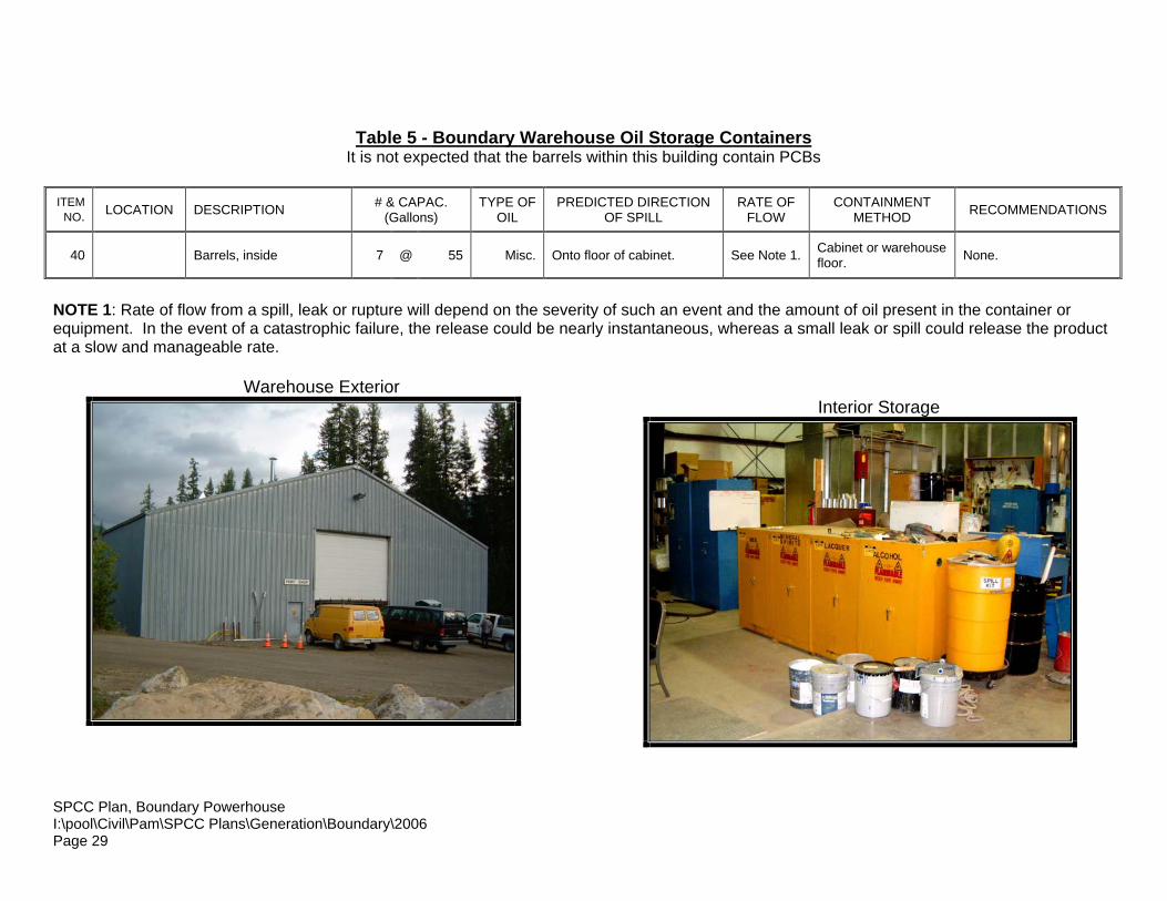
Table 5 - Boundary Warehouse Oil Storage ContainersIt is not expected that the barrels within this building contain PCBs
ITEMNO. LOCATION DESCRIPTION # & CAPAC.
(Gallons)TYPE OF
OILPREDICTED DIRECTION
OF SPILLRATE OF
FLOWCONTAINMENT
METHOD RECOMMENDATIONS
40 Barrels, inside 7 @ 55 Misc. Onto floor of cabinet. See Note 1. Cabinet or warehousefloor. None.
NOTE 1: Rate of flow from a spill, leak or rupture will depend on the severity of such an event and the amount of oil present in the container orequipment. In the event of a catastrophic failure, the release could be nearly instantaneous, whereas a small leak or spill could release the productat a slow and manageable rate.
Warehouse ExteriorInterior Storage
SPCC Plan, Boundary PowerhouseI:\pool\Civil\Pam\SPCC Plans\Generation\Boundary\2006Page 30
Discussion.
The maximum anticipated spill is 55-gallons from one of the drums of miscellaneous oil productsstored in the interior. No drain was found during the inspection and no drain was noted on theas-built drawings. A spill would spread onto the concrete floor where it would be cleaned up. Itis unlikely that a spill could reach a door and flow onto the ground.
The warehouse is also used as the storage location for the facilities’ waste materials, i.e. beadblasting sand, scrap equipment, dross (welding waste) and general garbage.
SPCC Plan, Boundary PowerhouseI:\pool\Civil\Pam\SPCC Plans\Generation\Boundary\2006Page 31
VI. DISCHARGE PREVENTION MEASURES (PRODUCT LOADING/UNLOADING)
Whenever oil is loaded or unloaded at this facility personnel are present to witness theentire operation. Suitable spill kit supplies are readily available should they be needed.
Any loading or unloading of oil products at the Powerhouse would occur at a locationwhere any spilled oil would either drain to the upper or lower sump.
Any loading or unloading of oil products at the Switchyard would occur at at locationwhere the spilled oil would enter the BPA oil containment system.
There are no policies or procedures in place regarding the transfer of oil at the facility.See Section X “Recommendations”.
SPCC Plan, Boundary PowerhouseI:\pool\Civil\Pam\SPCC Plans\Generation\Boundary\2006Page 32
VII. INSPECTIONS, TESTS, AND RECORDS
40 CFR 112.7(e) requires that regulated facilities develop and implement inspection,testing and recordkeeping procedures. This section documents procedures specific to thevarious areas of the Boundary Powerhouse facility.
A. Inspections
All inspections of oil-filled electrical equipment, bulk storage containers, and oilcontainment systems are conducted by plant Operators on a weekly basis. For thepurposes of this SPCC plan, inspection means a thorough visual examination. Theoperator will look for signs of deterioration, leaks, or other conditions that may causea leak or spill. The inspection of the equipment or storage containers shall includeany associated piping, flanges, valves, and containment systems.
B. Tests
40 CFR 112.8 (c)(6) requires that all bulk storage containers receive periodicintegrity testing. Electrical equipment is NOT considered bulk storage. Per theEPA, visual inspections of aboveground tanks that are not in contact with theground and can be seen from all sides would be considered an equivalentenvironmental protection and no integrity testing is required.
Per Tom Shinault's (EPA Region 10) e-mail of 1/10/03, we understand that EPAconsiders integrity testing beyond visual inspection of 55 gallon drums contrary tocommon sense. We concur with this assessment in "appropriate circumstances".By "appropriate circumstances", we mean: (1) drums not placed directly on theground, and (2) drums situated such that there is no danger of an oil spill making itsway to navigable waters. SCL will conduct periodic visual inspections as discussedin the preceding section.
The oil detection system in the upper and lower powerhouse sumps is tested on ayearly basis.
C. Records
Each inspection must be documented using the inspection forms included inAppendix "C". Any long-term leaking equipment or containers are documented onthe inspection forms. Long-term is defined as being longer than 6 months to makea repair or replace the equipment or container. Any newly leaking equipment orcontainers are also noted. For both new and long-term leaks the type of leak, actiontaken, and expected time-frame is documented on the inspection form.
Records of the inspections described above must be kept at the BoundaryPowerhouse. The inspection records must be kept with the SPCC Plan at thefacility for three years per 40 CFR 112.7(e), and must be readily available uponrequest. The Environment and Safety Division may request copies of the recordsperiodically. The person currently responsible for maintaining the required recordsis:
Lonnie Johnson – PAX 28-3214, or (509)446-3083
SPCC Plan, Boundary PowerhouseI:\pool\Civil\Pam\SPCC Plans\Generation\Boundary\2006Page 33
VIII. PERSONNEL TRAINING FOR DISCHARGE PREVENTION PROCEDURES
All of the Boundary Powerhouse crew members will likely be involved in oil handling fromtime to time. Therefore, as required by 40 CRF 112.7, they must all receive annual SPCCtraining. SPCC training for Boundary Powerhouse will include the following topics:
• Overview of applicable regulations – 40 CFR 112 and WAC 296-824
• Overview of SPCC Plan
• Review of regulated equipment – for each piece of equipment, the followinginformation will be covered:
a. Description of existing containment
b. Review of maintenance/calibration procedures
c. Review of inspection procedures
d. Review of spill response procedures
e. Review of any spills within the past year
• Review of spill response supplies, including quantity, type and location.
• Related training needs (confined space entry, spill response, etc)
In addition to the SPCC plan training, Federal and State Safety regulations require thatemployees who have responsibilities for emergency spill response receive certain safetytraining. The amount of training depends on the duties they are expected to perform inthe event of a spill. A summary of the duties and associated training levels is providedbelow. A more detailed description of the duties of the various levels is included inSection IV ("What To Do in the Event of an Oil Spill").
Workers who engage in spill response may require additional training such as confinedspace, lock-out/tag-out, fall protection or others depending on how and where the spillresponse activities will likely occur. It is the responsibility of the Facility Supervisor toensure workers receive this additional training as needed.
Records of SPCC Plan training, emergency spill response training, and any otherpertinent training will be maintained in Appendix "E" to this plan.

SPCC Plan, Boundary PowerhouseI:\pool\Civil\Pam\SPCC Plans\Generation\Boundary\2006Page 34
IX. SECURITY
In general, doors are locked when a building is unattended. There are security camerasthroughout the site that are controlled and monitored from the control room in thepowerhouse.
All visitors are under escort until leaving the facility.
A. Powerhouse
All restricted areas of this facility are under lock and key or other controlled access.All visitors are under escort until exiting the facility.
B. Switchyard
The switchyard is fully fenced. Gates in the fence are locked. Doors to thesubstation building are locked.
C. Dam
The gate controlling access across the dam is kept locked at all times. During thetourist season (June to September), visitors are accompanied by a guide whencrossing the dam or en route to the Vista House.
D. Oil Storage Building
The doors are kept locked at all times when the building is unattended.
E. Garage
Garage doors are kept locked at all times when the building is unattended
F. Warehouse
Doors to the warehouse are kept locked at all times when the building isunattended.
G. Forebay Building
Doors to the Forebay building are kept locked at all times when the building isunattended.
SPCC Plan, Boundary PowerhouseI:\pool\Civil\Pam\SPCC Plans\Generation\Boundary\2006Page 35
X. RECOMMENDATIONS
Mid-Term Recommendations.
The following mid-term measures (6-12 months) are recommended for this facility.
1. Training.
Train personnel on the SPCC Plan per Section VIII "Personnel Training forDischarge Prevention Procedures".
2. Integrity testing of the 5,000 gallon used oil tank near the end of the muckingtunnel.
The 5,000 gallon tank is encased in concrete. The SPCC regulations requireintegrity testing of these types of tanks. However the tank technically meetsthe definition of an underground storage tank (UST). If the tank wereregistered with the DOE then it would no longer need to be considered as partof the SPCC plan and would fall under the regulations for USTs. But the tankcannot be registered with DOE because it does not have monitoringequipment and would be considered out of compliance with UST regulations.Evaluate options such as whether to remove the tank, replace the tank, installmonitoring equipment, or close it in place. Implement the preferredalternative.
Long -Term Recommendations
The following long-term measures (1-2 years) are recommended for this facility.
1. Oil Spill in the Powerhouse
In a large scale event involving the loss of all oil in a transformer there is onlyapproximately one hour before the powerhouse sump pumps will beginoperation again. Evaluate how we would respond to such an event and whatways we might be able to prevent oil being released into the river. Implementthe preferred alternative.
SPCC Plan, Boundary PowerhouseI:\pool\Civil\Pam\SPCC Plans\Generation\Boundary\2006Page 36
XI. APPENDICES
Appendix "A" Facility Diagrams
Appendix "B" Oil Containment System Capacity Calculations
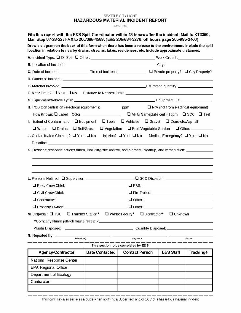
Appendix “C” Hazardous Material Incident Report Form (309-L 1-03)
Appendix “D” Inspection Forms
Appendix “E” Training Records
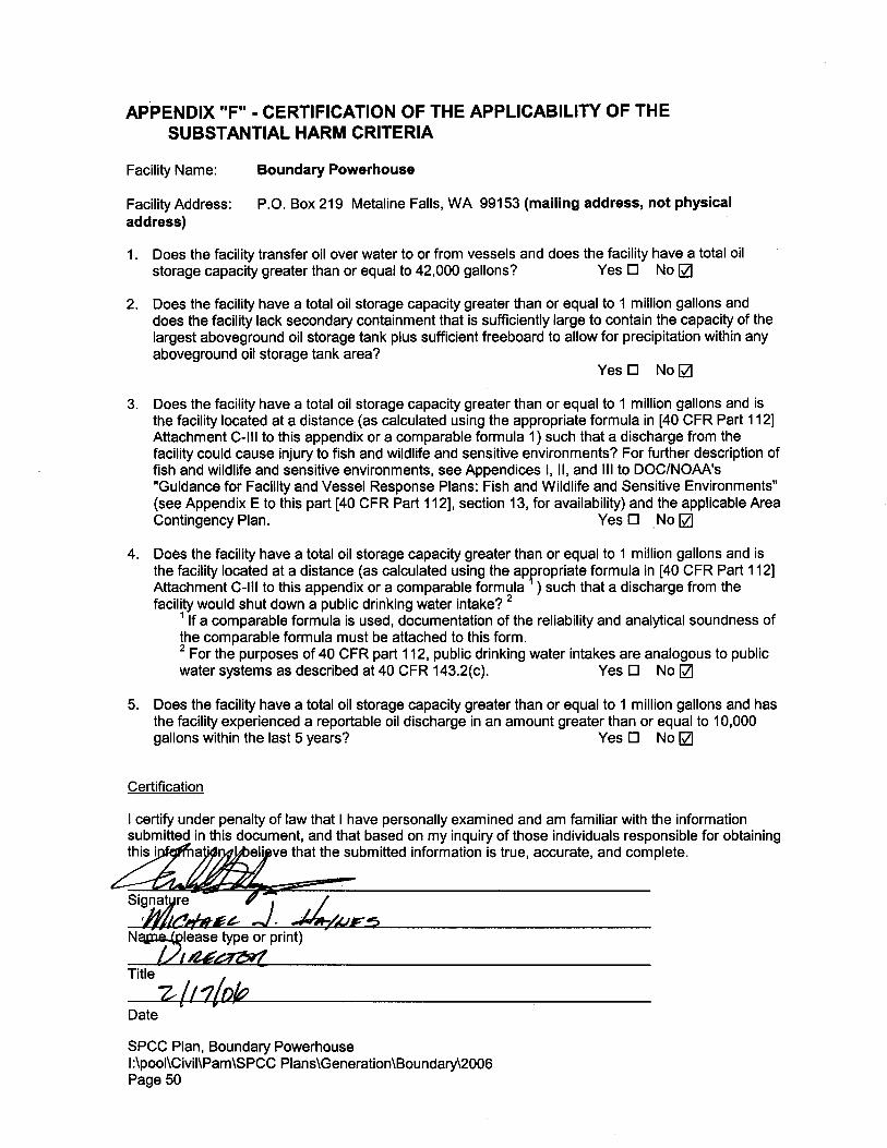
Appendix “F” Certification of the Applicability of the Substantial Harm Criteria
Appendix “G” SCL Personnel List for Oil Spill Issues
SPCC Plan, Boundary PowerhouseI:\pool\Civil\Pam\SPCC Plans\Generation\Boundary\2006Page 37
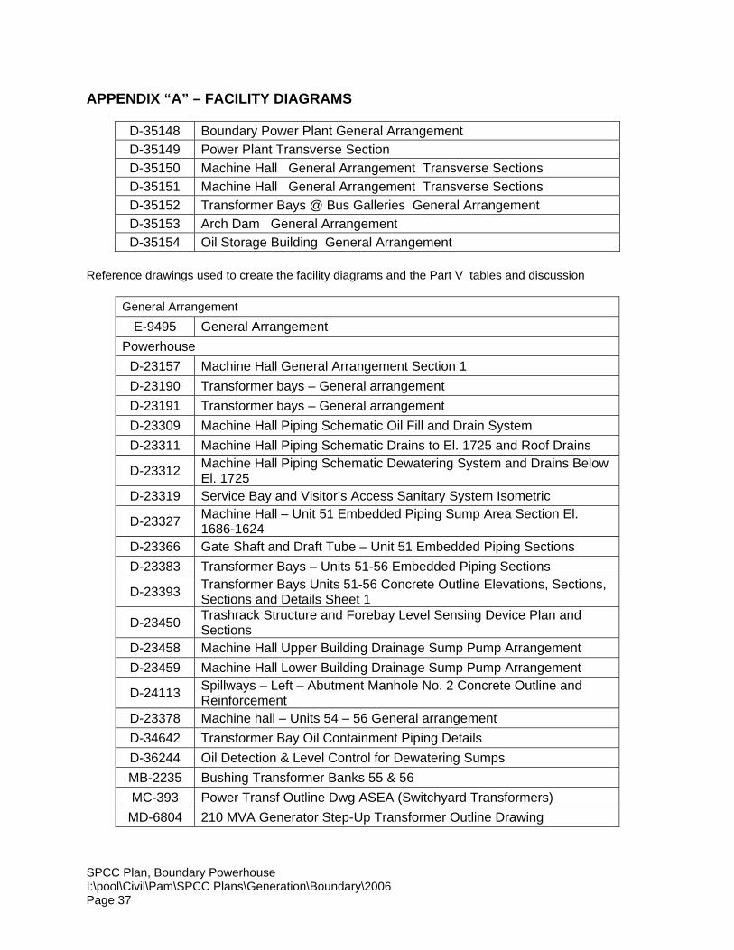
APPENDIX “A” – FACILITY DIAGRAMS
D-35148 Boundary Power Plant General ArrangementD-35149 Power Plant Transverse SectionD-35150 Machine Hall General Arrangement Transverse SectionsD-35151 Machine Hall General Arrangement Transverse SectionsD-35152 Transformer Bays @ Bus Galleries General ArrangementD-35153 Arch Dam General ArrangementD-35154 Oil Storage Building General Arrangement
Reference drawings used to create the facility diagrams and the Part V tables and discussion
General Arrangement
E-9495 General ArrangementPowerhouse
D-23157 Machine Hall General Arrangement Section 1D-23190 Transformer bays – General arrangementD-23191 Transformer bays – General arrangementD-23309 Machine Hall Piping Schematic Oil Fill and Drain SystemD-23311 Machine Hall Piping Schematic Drains to El. 1725 and Roof Drains
D-23312 Machine Hall Piping Schematic Dewatering System and Drains BelowEl. 1725
D-23319 Service Bay and Visitor’s Access Sanitary System Isometric
D-23327 Machine Hall – Unit 51 Embedded Piping Sump Area Section El.1686-1624
D-23366 Gate Shaft and Draft Tube – Unit 51 Embedded Piping SectionsD-23383 Transformer Bays – Units 51-56 Embedded Piping Sections
D-23393 Transformer Bays Units 51-56 Concrete Outline Elevations, Sections,Sections and Details Sheet 1
D-23450 Trashrack Structure and Forebay Level Sensing Device Plan andSections
D-23458 Machine Hall Upper Building Drainage Sump Pump ArrangementD-23459 Machine Hall Lower Building Drainage Sump Pump Arrangement
D-24113 Spillways – Left – Abutment Manhole No. 2 Concrete Outline andReinforcement
D-23378 Machine hall – Units 54 – 56 General arrangementD-34642 Transformer Bay Oil Containment Piping DetailsD-36244 Oil Detection & Level Control for Dewatering SumpsMB-2235 Bushing Transformer Banks 55 & 56MC-393 Power Transf Outline Dwg ASEA (Switchyard Transformers)
MD-6804 210 MVA Generator Step-Up Transformer Outline Drawing

SPCC Plan, Boundary PowerhouseI:\pool\Civil\Pam\SPCC Plans\Generation\Boundary\2006Page 38
DamD-23074 Arch dam - Upstream elevationD-23075 Arch dam - Downstream elevation
Oil House
D-24193 Oil Storage Building Concrete Outline, Plans and SectionsGarage
D-19061 City Construction Camp 60 feet by 160 feet Prefab Metal Warehouseand Garage Building
Shipping & Receiving BuildingD-32941 Sit Grading, Paving , and Utility PlanD-32948 Structural Foundation Plan
Warehouse
D-19165 Construction Camp 80 x 360 Storage Building #2 Foundation Plan &Details
SwitchyardMC-393 Power Transf Outline Dwg ASEA (Switchyard Transformers)
Boun51_SPCC PDF version of BPA SPCC drawing for the switchyard

[Note: Per guidance from the Federal Energy Regulatory Commission (FERC), project facility drawings contain Critical Energy Infrastructure Information (CEII) and have therefore been omitted from general distribution in the License Application. This information has been filed with FERC with a CEII designation in Volume 3 of the License Application submittal. Procedures for obtaining access to CEII may be found at 18 CFR§ 388.113. Requests for access to CEII should be made to FERC's CEII coordinator.]
Boundary power plant general arrangement

[Note: Per guidance from the Federal Energy Regulatory Commission (FERC), project facility drawings contain Critical Energy Infrastructure Information (CEII) and have therefore been omitted from general distribution in the License Application. This information has been filed with FERC with a CEII designation in Volume 3 of the License Application submittal. Procedures for obtaining access to CEII may be found at 18 CFR§ 388.113. Requests for access to CEII should be made to FERC's CEII coordinator.]
Machine hall and service bay floor plans
[Note: Per guidance from the Federal Energy Regulatory Commission (FERC), project facility drawings contain Critical Energy Infrastructure Information (CEII) and have therefore been omitted from general distribution in the License Application. This information has been filed with FERC with a CEII designation in Volume 3 of the License Application submittal. Procedures for obtaining access to CEII may be found at 18 CFR§ 388.113. Requests for access to CEII should be made to FERC's CEII coordinator.]
Machine hall general arrangement transverse sections

[Note: Per guidance from the Federal Energy Regulatory Commission (FERC), project facility drawings contain Critical Energy Infrastructure Information (CEII) and have therefore been omitted from general distribution in the License Application. This information has been filed with FERC with a CEII designation in Volume 3 of the License Application submittal. Procedures for obtaining access to CEII may be found at 18 CFR§ 388.113. Requests for access to CEII should be made to FERC's CEII coordinator.]
Power plant transverse section

[Note: Per guidance from the Federal Energy Regulatory Commission (FERC), project facility drawings contain Critical Energy Infrastructure Information (CEII) and have therefore been omitted from general distribution in the License Application. This information has been filed with FERC with a CEII designation in Volume 3 of the License Application submittal. Procedures for obtaining access to CEII may be found at 18 CFR§ 388.113. Requests for access to CEII should be made to FERC's CEII coordinator.]
Transformer bays at bus galleries transverse sections

[Note: Per guidance from the Federal Energy Regulatory Commission (FERC), project facility drawings contain Critical Energy Infrastructure Information (CEII) and have therefore been omitted from general distribution in the License Application. This information has been filed with FERC with a CEII designation in Volume 3 of the License Application submittal. Procedures for obtaining access to CEII may be found at 18 CFR§ 388.113. Requests for access to CEII should be made to FERC's CEII coordinator.]
Arch dam general arrangement

[Note: Per guidance from the Federal Energy Regulatory Commission (FERC), project facility drawings contain Critical Energy Infrastructure Information (CEII) and have therefore been omitted from general distribution in the License Application. This information has been filed with FERC with a CEII designation in Volume 3 of the License Application submittal. Procedures for obtaining access to CEII may be found at 18 CFR§ 388.113. Requests for access to CEII should be made to FERC's CEII coordinator.]
Oil storage building general arrangement

SPCC Plan, Boundary PowerhouseI:\pool\Civil\Pam\SPCC Plans\Generation\Boundary\2006Page 39
APPENDIX “B” – OIL CONTAINMENT SYSTEM CAPACITY CALCULATIONS
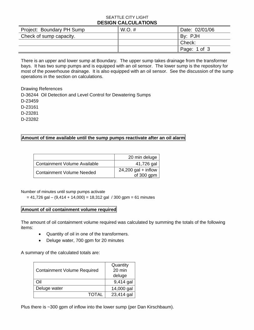
SEATTLE CITY LIGHT DESIGN CALCULATIONS
Project: Boundary PH Sump W.O. # Date: 02/01/06 Check of sump capacity. By: PJH Check: Page: 1 of 3
There is an upper and lower sump at Boundary. The upper sump takes drainage from the transformer bays. It has two sump pumps and is equipped with an oil sensor. The lower sump is the repository for most of the powerhouse drainage. It is also equipped with an oil sensor. See the discussion of the sump operations in the section on calculations. Drawing References D-36244 Oil Detection and Level Control for Dewatering Sumps D-23459 D-23161 D-23281 D-23282 Amount of time available until the sump pumps reactivate after an oil alarm
20 min delugeContainment Volume Available 41,726 gal
Containment Volume Needed 24,200 gal + inflow of 300 gpm
Number of minutes until sump pumps activate = 41,726 gal – (9,414 + 14,000) = 18,312 gal / 300 gpm = 61 minutes Amount of oil containment volume required The amount of oil containment volume required was calculated by summing the totals of the following items:
• Quantity of oil in one of the transformers. • Deluge water, 700 gpm for 20 minutes
A summary of the calculated totals are:
Containment Volume Required Quantity 20 min deluge
Oil 9,414 galDeluge water 14,000 gal
TOTAL 23,414 gal Plus there is ~300 gpm of inflow into the lower sump (per Dan Kirschbaum).
SEATTLE CITY LIGHT DESIGN CALCULATIONS
Project: Boundary PH Sump W.O. # Date: 02/01/06 Check of sump capacity. By: PJH Check: Page: 2 of 3
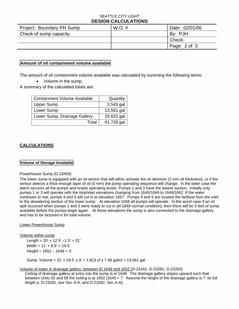
Amount of oil containment volume available The amount of oil containment volume available was calculated by summing the following items:
• Volume in the sump. A summary of the calculated totals are:
Containment Volume Available Quantity Upper Sump 2,543 galLower Sump 13,561 galLower Sump, Drainage Gallery 25,622 gal
Total 41,726 gal CALCULATIONS Volume of Storage Available Powerhouse Sump (D-23459) The lower sump is equipped with an oil sensor that will either activate the oil skimmer (2 mm oil thickness), or if the sensor detects a thick enough layer of oil (5 mm) the pump operating sequence will change. In the latter case the alarm secures all the pumps and resets operating levels. Pumps 1 and 3 have the lowest suction. Initially only pumps 1 or 3 will operate with the stop/start elevations changing from 1645/1649 to 1649/1652. If the water continues to rise, pumps 4 and 5 will cut in at elevation 1657. Pumps 4 and 5 are located the farthest from the inlet to the dewatering section of the lower sump. At elevation 1658 all pumps will operate. In the worst case if an oil spill occurred when pumps 1 and 3 were ready to cut in (el 1649 normal condition), then there will be 3 feet of sump available before the pumps begin again. At these elevations the sump is also connected to the drainage gallery and has to be factored in for total volume. Lower Powerhouse Sump Volume within sump
Length = 20’ + 12.5’ –1.5’ = 31’ Width = 11’ + 8.5’ = 19.5’ Height = 1652 – 1649 = 3’
Sump, Volume = 31’ x 19.5’ x 3’ = 1,813 cf x 7.48 gal/cf = 13,561 gal
Volume of water in drainage gallery, between El 1649 and 1652 (D-23161, D-23281, D-23282)
Ceiling of drainage gallery at entry into the sump is el 1649. The drainage gallery slopes upward such that between Units 55 and 56 the ceiling is at 1652 (1645 + 7. Assume the height of the drainage gallery is 7’ its full length p. D-23281, see Sec A-A, and D-23282, Sec A-A).
SEATTLE CITY LIGHT DESIGN CALCULATIONS
Project: Boundary PH Sump W.O. # Date: 02/01/06 Check of sump capacity. By: PJH Check: Page: 3 of 3
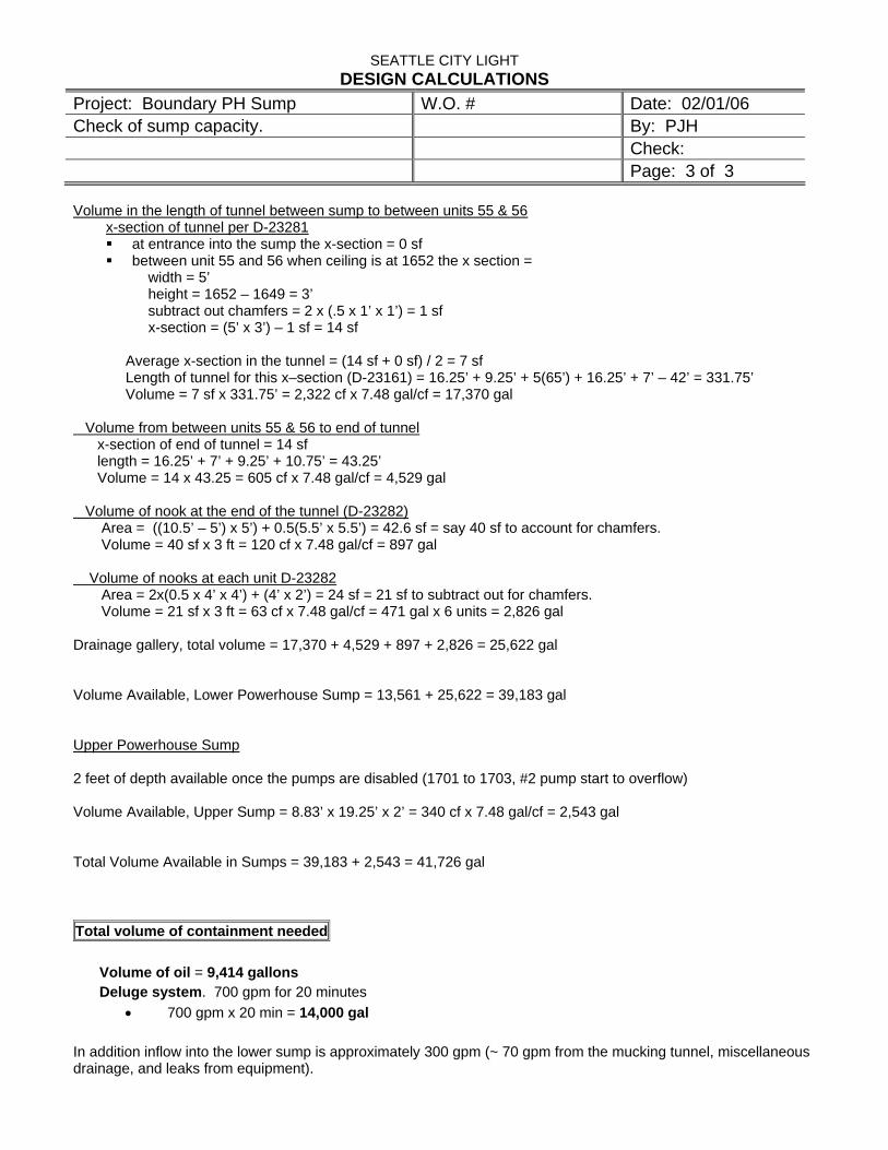
Volume in the length of tunnel between sump to between units 55 & 56
x-section of tunnel per D-23281 at entrance into the sump the x-section = 0 sf between unit 55 and 56 when ceiling is at 1652 the x section =
width = 5’ height = 1652 – 1649 = 3’ subtract out chamfers = 2 x (.5 x 1’ x 1’) = 1 sf x-section = (5’ x 3’) – 1 sf = 14 sf
Average x-section in the tunnel = (14 sf + 0 sf) / 2 = 7 sf Length of tunnel for this x–section (D-23161) = 16.25’ + 9.25’ + 5(65’) + 16.25’ + 7’ – 42’ = 331.75’ Volume = 7 sf x 331.75’ = 2,322 cf x 7.48 gal/cf = 17,370 gal
Volume from between units 55 & 56 to end of tunnel x-section of end of tunnel = 14 sf length = 16.25’ + 7’ + 9.25’ + 10.75’ = 43.25’ Volume = 14 x 43.25 = 605 cf x 7.48 gal/cf = 4,529 gal Volume of nook at the end of the tunnel (D-23282) Area = ((10.5’ – 5’) x 5’) + 0.5(5.5’ x 5.5’) = 42.6 sf = say 40 sf to account for chamfers. Volume = 40 sf x 3 ft = 120 cf x 7.48 gal/cf = 897 gal Volume of nooks at each unit D-23282 Area = 2x(0.5 x 4’ x 4’) + (4’ x 2’) = 24 sf = 21 sf to subtract out for chamfers. Volume = 21 sf x 3 ft = 63 cf x 7.48 gal/cf = 471 gal x 6 units = 2,826 gal Drainage gallery, total volume = 17,370 + 4,529 + 897 + 2,826 = 25,622 gal Volume Available, Lower Powerhouse Sump = 13,561 + 25,622 = 39,183 gal Upper Powerhouse Sump 2 feet of depth available once the pumps are disabled (1701 to 1703, #2 pump start to overflow) Volume Available, Upper Sump = 8.83’ x 19.25’ x 2’ = 340 cf x 7.48 gal/cf = 2,543 gal Total Volume Available in Sumps = 39,183 + 2,543 = 41,726 gal Total volume of containment needed
Volume of oil = 9,414 gallons Deluge system. 700 gpm for 20 minutes
• 700 gpm x 20 min = 14,000 gal In addition inflow into the lower sump is approximately 300 gpm (~ 70 gpm from the mucking tunnel, miscellaneous drainage, and leaks from equipment).

SPCC Plan, Boundary PowerhouseI:\pool\Civil\Pam\SPCC Plans\Generation\Boundary\2006Page 40
APPENDIX “C” - HAZARDOUS MATERIAL INCIDENT REPORT FORM
SPCC Plan, Boundary PowerhouseI:\pool\Civil\Pam\SPCC Plans\Generation\Boundary\2006Page 41

SPCC Plan, Boundary PowerhouseI:\pool\Civil\Pam\SPCC Plans\Generation\Boundary\2006Page 42
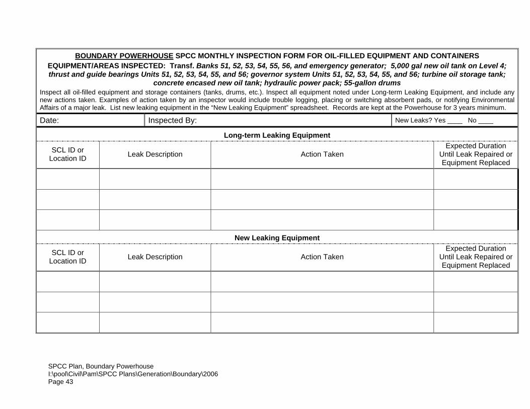
APPENDIX “D” - INSPECTION FORMS
SPCC Plan, Boundary Powerhouse I:\pool\Civil\Pam\SPCC Plans\Generation\Boundary\2006 Page 43
BOUNDARY POWERHOUSE SPCC MONTHLY INSPECTION FORM FOR OIL-FILLED EQUIPMENT AND CONTAINERS EQUIPMENT/AREAS INSPECTED: Transf. Banks 51, 52, 53, 54, 55, 56, and emergency generator; 5,000 gal new oil tank on Level 4; thrust and guide bearings Units 51, 52, 53, 54, 55, and 56; governor system Units 51, 52, 53, 54, 55, and 56; turbine oil storage tank;
concrete encased new oil tank; hydraulic power pack; 55-gallon drums Inspect all oil-filled equipment and storage containers (tanks, drums, etc.). Inspect all equipment noted under Long-term Leaking Equipment, and include any new actions taken. Examples of action taken by an inspector would include trouble logging, placing or switching absorbent pads, or notifying Environmental Affairs of a major leak. List new leaking equipment in the “New Leaking Equipment” spreadsheet. Records are kept at the Powerhouse for 3 years minimum. Date: Inspected By: New Leaks? Yes ____ No ____
Long-term Leaking Equipment
SCL ID or Location ID Leak Description Action Taken
Expected Duration Until Leak Repaired or Equipment Replaced
New Leaking Equipment
SCL ID or Location ID Leak Description Action Taken
Expected Duration Until Leak Repaired or Equipment Replaced
SPCC Plan, Boundary Powerhouse I:\pool\Civil\Pam\SPCC Plans\Generation\Boundary\2006 Page 44
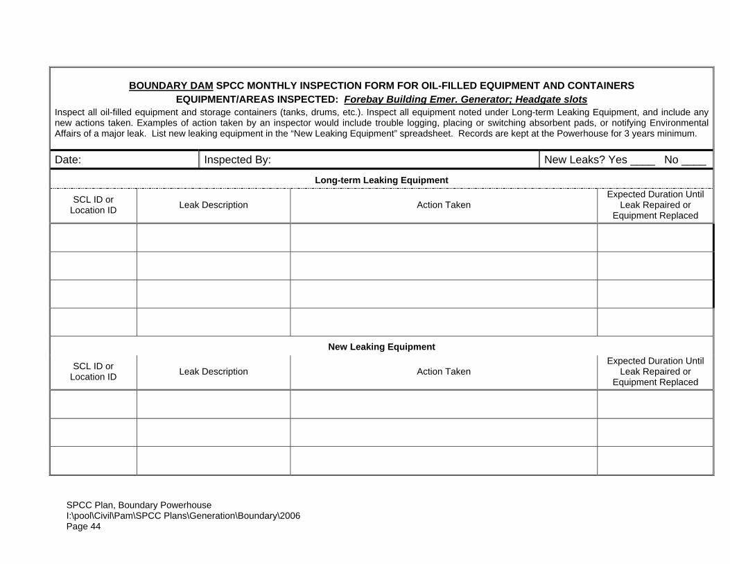
BOUNDARY DAM SPCC MONTHLY INSPECTION FORM FOR OIL-FILLED EQUIPMENT AND CONTAINERS EQUIPMENT/AREAS INSPECTED: Forebay Building Emer. Generator; Headgate slots
Inspect all oil-filled equipment and storage containers (tanks, drums, etc.). Inspect all equipment noted under Long-term Leaking Equipment, and include any new actions taken. Examples of action taken by an inspector would include trouble logging, placing or switching absorbent pads, or notifying Environmental Affairs of a major leak. List new leaking equipment in the “New Leaking Equipment” spreadsheet. Records are kept at the Powerhouse for 3 years minimum.
Date: Inspected By: New Leaks? Yes ____ No ____
Long-term Leaking Equipment
SCL ID or Location ID Leak Description Action Taken
Expected Duration Until Leak Repaired or
Equipment Replaced
New Leaking Equipment
SCL ID or Location ID Leak Description Action Taken
Expected Duration Until Leak Repaired or
Equipment Replaced
SPCC Plan, Boundary Powerhouse I:\pool\Civil\Pam\SPCC Plans\Generation\Boundary\2006 Page 45
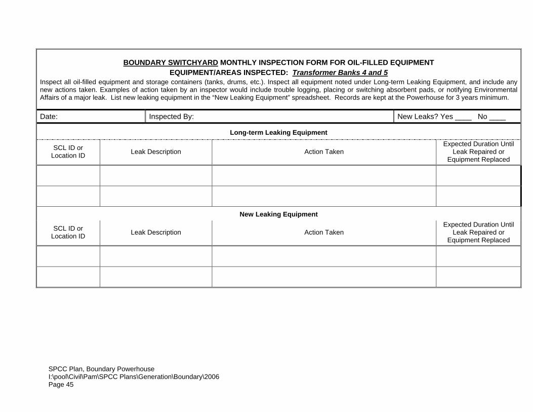
BOUNDARY SWITCHYARD MONTHLY INSPECTION FORM FOR OIL-FILLED EQUIPMENT EQUIPMENT/AREAS INSPECTED: Transformer Banks 4 and 5
Inspect all oil-filled equipment and storage containers (tanks, drums, etc.). Inspect all equipment noted under Long-term Leaking Equipment, and include any new actions taken. Examples of action taken by an inspector would include trouble logging, placing or switching absorbent pads, or notifying Environmental Affairs of a major leak. List new leaking equipment in the “New Leaking Equipment” spreadsheet. Records are kept at the Powerhouse for 3 years minimum.
Date: Inspected By: New Leaks? Yes ____ No ____
Long-term Leaking Equipment
SCL ID or Location ID Leak Description Action Taken
Expected Duration Until Leak Repaired or
Equipment Replaced
New Leaking Equipment
SCL ID or Location ID Leak Description Action Taken
Expected Duration Until Leak Repaired or
Equipment Replaced
SPCC Plan, Boundary Powerhouse I:\pool\Civil\Pam\SPCC Plans\Generation\Boundary\2006 Page 46
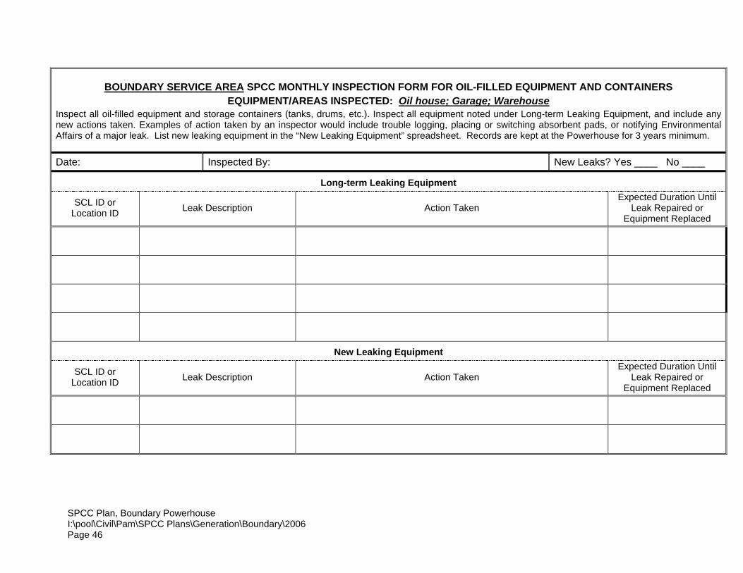
BOUNDARY SERVICE AREA SPCC MONTHLY INSPECTION FORM FOR OIL-FILLED EQUIPMENT AND CONTAINERS EQUIPMENT/AREAS INSPECTED: Oil house; Garage; Warehouse
Inspect all oil-filled equipment and storage containers (tanks, drums, etc.). Inspect all equipment noted under Long-term Leaking Equipment, and include any new actions taken. Examples of action taken by an inspector would include trouble logging, placing or switching absorbent pads, or notifying Environmental Affairs of a major leak. List new leaking equipment in the “New Leaking Equipment” spreadsheet. Records are kept at the Powerhouse for 3 years minimum.
Date: Inspected By: New Leaks? Yes ____ No ____
Long-term Leaking Equipment
SCL ID or Location ID Leak Description Action Taken
Expected Duration Until Leak Repaired or
Equipment Replaced
New Leaking Equipment
SCL ID or Location ID Leak Description Action Taken
Expected Duration Until Leak Repaired or
Equipment Replaced
SPCC Plan, Boundary Powerhouse I:\pool\Civil\Pam\SPCC Plans\Generation\Boundary\2006 Page 47
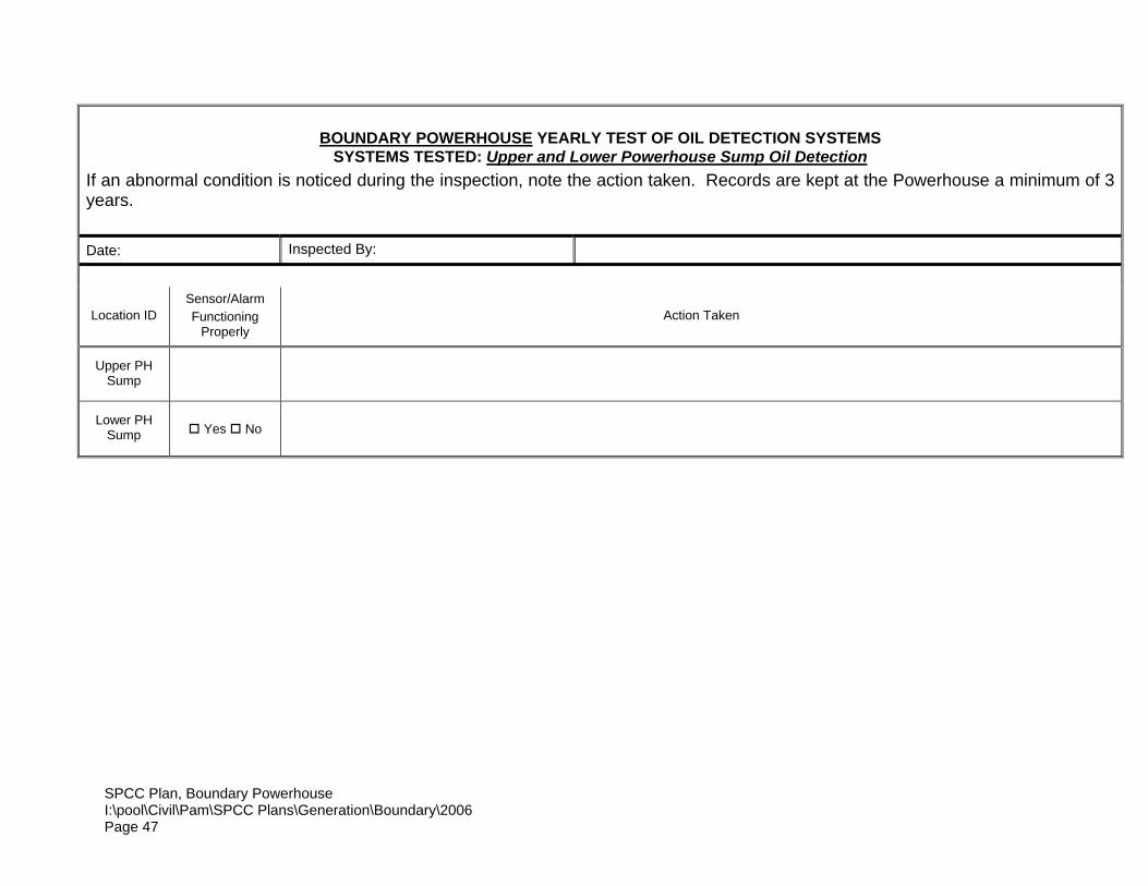
BOUNDARY POWERHOUSE YEARLY TEST OF OIL DETECTION SYSTEMS SYSTEMS TESTED: Upper and Lower Powerhouse Sump Oil Detection
If an abnormal condition is noticed during the inspection, note the action taken. Records are kept at the Powerhouse a minimum of 3 years.
Date: Inspected By:
Location ID Sensor/Alarm Functioning
Properly Action Taken
Upper PH Sump
Lower PH Sump Yes No

SPCC Plan, Boundary PowerhouseI:\pool\Civil\Pam\SPCC Plans\Generation\Boundary\2006Page 48
APPENDIX "E" - TRAINING RECORDS
SPCC Plan, Boundary PowerhouseI:\pool\Civil\Pam\SPCC Plans\Generation\Boundary\2006Page 49
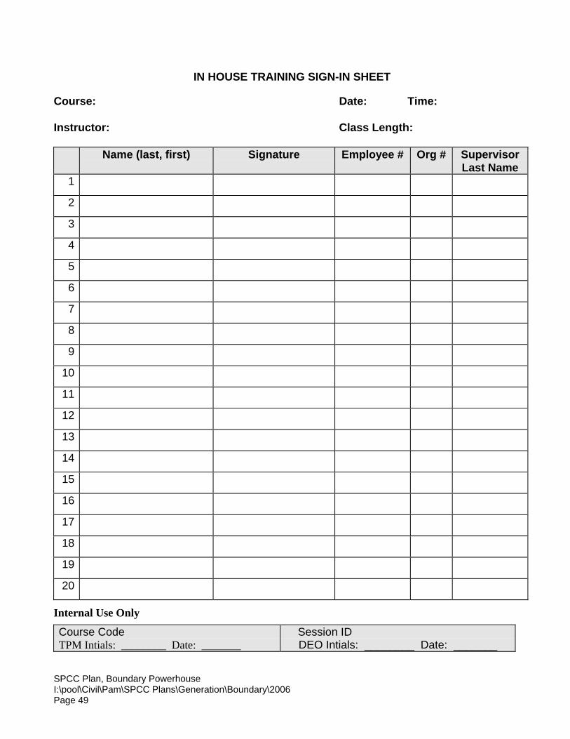
IN HOUSE TRAINING SIGN-IN SHEET
Course: Date: Time:
Instructor: Class Length:
Name (last, first) Signature Employee # Org # SupervisorLast Name
1
2
3
4
5
6
7
8
9
10
11
12
13
14
15
16
17
18
19
20
Internal Use Only
Course Code TPM Intials: ________ Date: _______
Session ID DEO Intials: ________ Date: _______
SPCC Plan, Boundary PowerhouseI:\pool\Civil\Pam\SPCC Plans\Generation\Boundary\2006Page 51
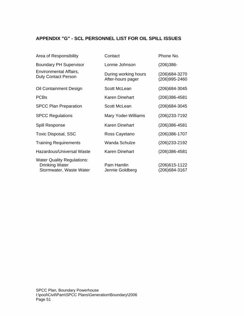
APPENDIX "G" - SCL PERSONNEL LIST FOR OIL SPILL ISSUES
Area of Responsibility Contact Phone No.
Boundary PH Supervisor Lonnie Johnson (206)386-Environmental Affairs,Duty Contact Person During working hours
After-hours pager(206)684-3270(206)995-2460
Oil Containment Design Scott McLean (206)684-3045
PCBs Karen Dinehart (206)386-4581
SPCC Plan Preparation Scott McLean (206)684-3045
SPCC Regulations Mary Yoder-Williams (206)233-7192
Spill Response Karen Dinehart (206)386-4581
Toxic Disposal, SSC Ross Cayetano (206)386-1707
Training Requirements Wanda Schulze (206)233-2192
Hazardous/Universal Waste Karen Dinehart (206)386-4581
Water Quality Regulations: Drinking Water Stormwater, Waste Water
Pam HamlinJennie Goldberg
(206)615-1122(206)684-3167
SPCC Plan, Boundary PowerhouseI:\pool\Civil\Pam\SPCC Plans\Generation\Boundary\2006Page 52
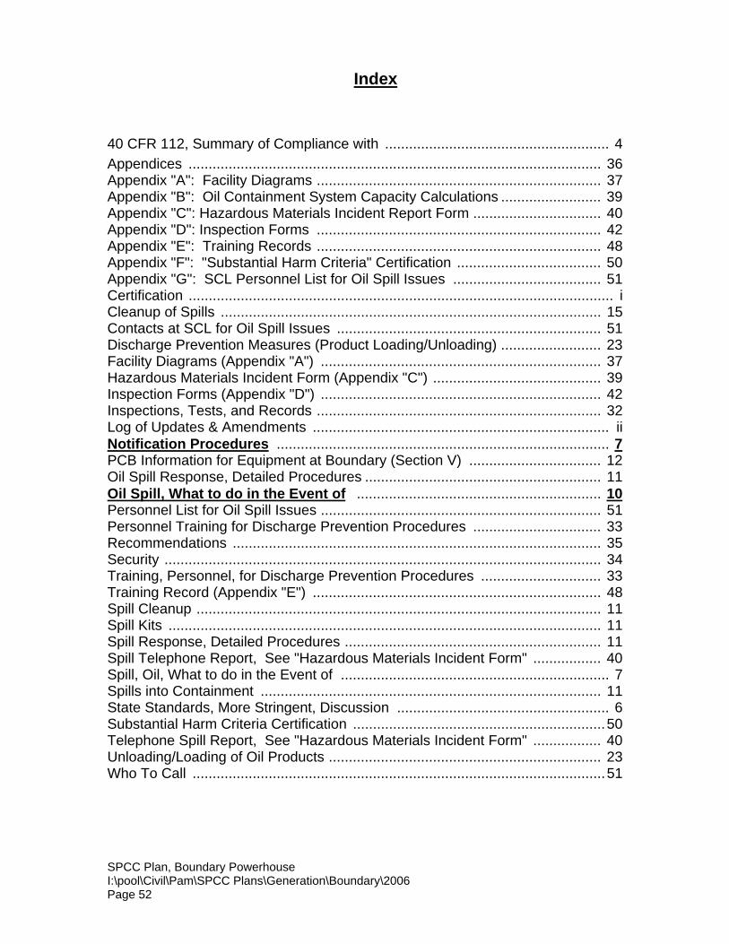
Index
40 CFR 112, Summary of Compliance with ........................................................ 4Appendices ....................................................................................................... 36Appendix "A": Facility Diagrams ....................................................................... 37Appendix "B": Oil Containment System Capacity Calculations ......................... 39Appendix "C": Hazardous Materials Incident Report Form ................................ 40Appendix "D": Inspection Forms ....................................................................... 42Appendix "E": Training Records ....................................................................... 48Appendix "F": "Substantial Harm Criteria" Certification .................................... 50Appendix "G": SCL Personnel List for Oil Spill Issues ..................................... 51Certification .......................................................................................................... iCleanup of Spills ............................................................................................... 15Contacts at SCL for Oil Spill Issues .................................................................. 51Discharge Prevention Measures (Product Loading/Unloading) ......................... 23Facility Diagrams (Appendix "A") ...................................................................... 37Hazardous Materials Incident Form (Appendix "C") .......................................... 39Inspection Forms (Appendix "D") ...................................................................... 42Inspections, Tests, and Records ....................................................................... 32Log of Updates & Amendments .......................................................................... iiNotification Procedures ................................................................................... 7PCB Information for Equipment at Boundary (Section V) ................................. 12Oil Spill Response, Detailed Procedures ........................................................... 11Oil Spill, What to do in the Event of ............................................................. 10Personnel List for Oil Spill Issues ...................................................................... 51Personnel Training for Discharge Prevention Procedures ................................ 33Recommendations ............................................................................................ 35Security ............................................................................................................. 34Training, Personnel, for Discharge Prevention Procedures .............................. 33Training Record (Appendix "E") ........................................................................ 48Spill Cleanup ..................................................................................................... 11Spill Kits ............................................................................................................ 11Spill Response, Detailed Procedures ................................................................ 11Spill Telephone Report, See "Hazardous Materials Incident Form" ................. 40Spill, Oil, What to do in the Event of ................................................................... 7Spills into Containment ..................................................................................... 11State Standards, More Stringent, Discussion ..................................................... 6Substantial Harm Criteria Certification ...............................................................50Telephone Spill Report, See "Hazardous Materials Incident Form" ................. 40Unloading/Loading of Oil Products .................................................................... 23Who To Call .......................................................................................................51