attachment 3 ocan071303 stator drop root cause …22kv voa~e raulaksi1617kv ris #3 sul #2su 16 ~ 6....
TRANSCRIPT

Attachment 3
OCAN071303
Stator Drop Root Cause Evaluation (Non-Proprietary)

7
I
ATTACHMENT 9.11 REPORT FORMAT
Page 1 of 189
Entergy Operations, Arkansas Nuclear One (ANO)
Root Cause Evaluation Report
Unit I Main Turbine Genbera Sttor
CR-ANO-C-2013-00888; Eve D1-2013
REPORT DAT 07-2213, Rev. 0
Position Date
Evaluator J.J. Nadeau 07-22-2013
Reviewer L.A. McCarty 07-22-2013
O&P Review S.C Marrs 07-22-2013
Responsible Manager .E. es 07-22-2013
CARB Chairpersum 07-22-2013
EN-LI-1 18, Attachment 9.11, Rev 18

I
ATTACHMENT 9.11 REPORT FORMAT
Page 2 of 189
Problem Statement
At approximately 0750 on 3/31/2013, during movement of the Unit 1 Main Turbine GeneratorStator (-524 tons), the temporary lift assembly failed resulting in loss of life, loss of'off-sitepower to Unit 1, structural damage to the Turbine Building and physical injuries.
Event Narrative
Event
Entergy Operations, Inc. (Entergy) contracted with ,Siemens Energy, Inc. (Siemens) toperform Generator Modernization on Unit 1 Main Turbine- Generator Stator (stator) duringArkansas Nuclear One (ANO) 1R24 refueling outage. Si'emens subcontracted with BiggeCrane and Rigging Co. (Bigge) for crane and.rigging services to remove the original statorand install the Unit 1 refurbished stator. A description ofýhe intended lift process is includedas Exhibit 1.
At the time of the event, ANO-2 was operating at 100% power and ANO-1 was in day sevenof the 1 R24 refueling outage. ANO-1 personnel had just completed filling the refueling canaland were in the process of checking out refueling equipment. The Bigge girders and strandjack lifting device had been raised-into place during the March 30th night shift and the lift ofthe stator had begun late in" that shift:
At approximately 0750 on March 31, 2013 the temporary lift assembly used to lift andtransport the ANO-1 stator ffro the turbine building. failed resulting in the -524 ton statordropping onto the ANO-i turbine deck (Elev. 386') and then rolling and falling onto thetransport vehicle p'rked in the train bay (Elev. 354'). Upon the failure of the lift assembly, itsstructu.ral members came down onto the ANO-1 and 2 turbine deck resulting in the death ofone individual, ten other injuries requiring offsite medical treatment, and multiple first aids.The impact ofAhe stator on the ANO-1 turbine deck resulted in substantial damage to turbinebuildl•g structural members and to the turbine deck floor itself in the vicinity of the impact.The 4160 VAC switchgear Al and A2 located immediately below where the stator impactedthe turbine deck were damaged, rendering offsite power sources from startup #1 and startup#2 transformers inoperable. The 4160 VAC supply to ANO-1 from Alternate AC Current(Black) Diesel Generator also was damaged.
EN-LI-118, Attachment 9.11, Rev 18

I
ATTACHMENT 9.11 REPORT FORMAT
Page 3 of 189Falling components impacted the north wall of the train bay causing structural damage,rupturing an 8" fire main and a 2'" hose reel supply resulting in substantial fire water sprayinto the train bay area. The stator came to rest against the south wall of the train bay on topof the transport vehicle. Both the north and south non-structural concrete masonry unit wallsof the train bay suffered substantial damage.
The shock caused by the temporary lift assembly failure and the stator falling was detectedby seismic Sensor XR-8007 located on the Unit 1 Spent Fuel Pool Deck (Elev. 404') jintheAuxiliary Building. The horizontal pseudo cumulative absolute velocity calc ulated-by-SensorXR-8007 was 0.01242g in the north-south direction and 0.02263g in the east-west direction.Both of these values are well below the 0.05g threshold for anticipated vibration-induceddamage. The other five seismic monitors installed at the station were functioning and did notexperience vibration above their recording triggers. There are two desigin basis earthquakesfor ANO: 0.1g Operating Basis Earthquake (OBE) and 0.2g Safe Shutdown Earthquake(SSE). Based on the calculated results, there is no indication that vibrations exceeding 0.1gOBE occurred.
The shock from the stator contacting the turbine building, and temporary lift assemblycomponents falling into the turbine building, caused relays; in the ANO-2 switchgear arealocated just adjacent to the train bay to actuate resulting in the trip of 2P-32B reactor coolantpump. This, in turn, resulted in a trip to the Unit 2'reactor, (CR-ANO-2-2013-00583). TheANO-2 post-trip response was normal wth the exception that the position indication for 2CV-0748 Feedwater Loop A Main Feedwater, Regulating Valve showed the valve to be 7.7%open, when in fact the valve had closed as designed (CR-ANO-2-2013-00823). In responseto this indication, the operators'\tripped thie main feedwater pumps and manually initiatedEmergency Feedwater.
The loss of offsite power to ANO-1 resulted in the automatic start and tie into their respectivesafety buses of both emergency,,diesel generators. Service water pumps automaticallystarted and restored hejaderpressure as designed. The ANO-1 operators restored decayheat removal-in a timely manner in accordance with OP-1203.028, Loss of Decay HeatRemoval. The; protected red train was placed in service first, with P34A Decay HeatRemoval (DHR) pump started at 0754 and DHR flow initiated at 0756. As a backup to P34A,P34B DHR pump was started at 0805 with its DHR flow path established at 0806. There areno bulk temperature readings available for the fuel transfer canal; however, during this periodthe E35A decay' heat outlet temperature increased from an approximate steady statetemper:ature. f`770F to approximately 850F.
Response to loss of spent fuel pool cooling was performed in accordance with AbnormalOperating Procedure OP-1203.050, Unit 1 Spent Fuel Pool Emergencies. Spent Fuel Pool(SFP) cooling flow was re-established at 0813 when P40B SFP Cooling Pump was started.Intermediate Cooling Water flow was momentarily established at approximately 0930, afteran offsite power source had been connected and established for longer-term operation
EN-LI-1 18, Attachment 9.11, Rev 18

I
ATTACHMENT 9.11 REPORT FORMAT
Page 4 of 189approximately one hour later at 1030. From 0750 to 1043, spent fuel pool temperature roseapproximately 2.8 0F from 87.0°F to a peak of 89.80 F (design temperature of the spent fuelpool is 2000F).
Immediate attempts were made by Operations personnel to isolate fire water spraying fromthe broken fire water piping into the train bay area. A field operator was dispatched to shutdown the fire water pumps in the ANO-1 intake structure. Power to the electric fire pumpwas lost due to damage to the A-1 switchgear. The field operator did not immediatelyrecognize a temporary electric motor-driven fire water pump was in service at thisý timesupplying water to the header (CR-ANO-C-2013-01072). The temporary fire water pumpwas subsequently secured. Spray from the fire water piping rupture, migrated into the ANO-2 switchgear area. The fire water that had pooled on the floor in the switchgear area enteredthe 2A1 switchgear at the location of the 2A-113 breaker cubicle zcausinrg -an electrical fault atapproximately 0923 on the 2A-1 4160V supply bus from start-up iran~sformer #3 (SU3). Thisfault resulted in a protective relaying lockout of SU3 which tripped all SU3 feeder and loadbreakers (CR-ANO-2-2013-00565). Switchgear 2A-2 was':deenergized following the SU3lockout resulting in a loss of offsite power to 2A-2 and 2A-4. ý,The 2K-4B emergency dieselgenerator started as designed and supplied safetybus 2A-4. Start-up transformer #2 (SU2)feed to 2A-2 breaker 2A-211 was in pull-to-lock per OP-2107.001 Electrical SystemOperation, (normal configuration). Switchgear 2A-• successfully slow transferred its feed toSU2 and provided power to 2A-1 and safety bus 2A-3. Switchgear 2A-1 remained energizedthroughout the event. Figure 1 depicts6th-eANO-Z high voltage distribution system.
EN-LI-1 18, Attachment 9.11, Rev 18

ATTAcHMENT 9.11 REPORT FOPmATATTACHMENT 9A I REPORT FORMATPage 5 of 189
4 C•rM3l V•*#
4 MTG 161 KV $-
BREAKERSVtaeRqitr AT
22KV Voa~e Raulaksi1617KV RIS#3 SUL #2SU
16 ~ 6. M4.I6
2H24 2AM2 2H2S
2A2
M*M
2X-31 ". ddining ZR14 wh., IM
2,.Iwnbn .d..ii.kbin6
Loss of SU3 90V buses 2H-1 and 2H-2 caused the loss of power to the two runningReactor Cos t(RCP) and the one running circulating water pump. Accordingly, theplant orato c ced a natural circulation cooldown using the atmospheric dumpvalves
The loss of bus 2-A2 resulted in a loss of power to one of two instrument air compressorsand the lowtransfer to SU2 resulted in the loss of the second instrument air compressor,which in combination with loss of both ANO-1 instrument air compressors, caused theinstrument air header which was cross-tied between the units to depressurize, complicatingthe ANO-2 response.
EN-LI-118, Attachment 9.11, Rev 18

I
ATTACHMENT 9.11 REPORT FORMAT
Page 6 of 189A Notification of Unusual Event (NUE) was declared at 1033, based on EAL HU-4, fire orexplosion, following confirmation that the lockout of SU3 was due to an electrical fault in theswitchgear at breaker 2A-1 13 with indications reported of bus damage.
The operator response to the event was effective with actions taken to maintain:the plants ina safe and stable condition despite the challenges associated with the lift assembly failure,medical response for injured personnel, and the challenges associated with degraded powercondition, Safety systems performed as designed, aiding the operators in the feventrecovery. Appropriate actions were taken on both units to respond to the, ,conditionýcreatedby the stator drop. The station's response ensured satisfaction of Entergy~s obligation toprotect public health and safety.
.S.An assessment of the ANO-1 Operations Response to the Event is ,contaidned in Exhibit 2a.An assessment of ANO-1 Equipment Response on 3/31/2013 is contained in Exhibit 2b. Anassessment of Unit 2 Operations response to the event is contained in Exhibit 3.
Scope
The scope of this Root Cause Evaluation (RCE) is to'-evaluate the cause of the temporary liftassembly failure and the consequences from.'a personnel safety and equipment damageperspective. Two firms were includedi!i the ,RCE-te.am to provide their independent subjectmatter expertise. performe.l evidence collection and structural analysis.
Ieva ealle organizational and programmatic controls associated withona andr¢ ontoluman peo rmance and industrial safety.,
Additional condition reports coosed-,to this RCE and how the CRs are addressed are identifiedin Attachment 7 - CR's losed to CR-ANO-C-2013-00888
The purpose of this RCE istoestablish corrective actions to assure that conditions that led tothe temporary lift assembly failure are promptly identified and corrected and that measuresnecessary to.prevent recurrence are identified and implemented.
Accessr'e:strictions by the stator contractor, Siemens, and its heavy lift subcontractor, Bigge,limited the ability'-of the Root Cause Team to further assess underlying causes. Had theRoot'Cause Team had full access to material, personnel and records related to the event, itappears•likelyfthat additional contributing causes may have been developed. Attachment 8identifies-some of the topics that would have been explored if access to the information andpersonnel were made available. Nonetheless, the information available was more thanadequate to identify why the event occurred and to identify corrective actions Entergy cantake to protect personnel and equipment.
EN-LI-1 18, Attachment 9.11, Rev 18

REPORTFORMA
ATTACHMENT 9.11
Page 7 of 189Root Cause Evaluation
REPORT FORMAT
Direct Cause
koft From
EN-LI-1 18, Attachment 9.11, Rev 18

ATTACHMENT 9.11
Page 8 of 189Event Scenario
REPORT FORMAT
EN-LI-1 18, Attachment 9.11, Rev 18

I
ATTAcHMENT 9.11 REPORT FORMATATTACHMENT 9.11 REPORT FORMAT
Ploe q of 189
EN-LI-118, Attachment 9.11, Rev 18

ATTACHMENT 9.11 REPORT FORMAT
EN-LI-118, Attachment 9. 11, Rev 18

I
ATTACHMENT 9.11
Page 11 of 189REPORT FORMAT
U
EN-LI-1i18, Attachment 9.11, Rev 18

ATTACHMENT 9.11PAnp 19 nf 1PAC
REPORT FORMAT
EN-LI-118, Attachment 9.11, Rev 18

I
ATTACHMENT 9.11 REPORT FORMATATTAC14MENT 9.11 REPORT FORMAT
I
I
EN-LI-118, Attachment 9.11, Rev 18

ATTAcHMENT9.11 REPORT FORMAT
EN-LI-1 18, Attachment 9.11, Rev 18

I
ATTAcHMENT 9.11
Dnrum 1 A nf 1 AQ
REPORT FORMATATTACHMENT 9.11 REPORT FORMAT
EN-LI-118,. Attachment 9.11, Rev 18

I
REPORT FORMAT
Analysis
EN-LI-1l18, Attachment 9.11, Rev 18

ATTACHMENT 9.1.1
Pa~qe 17.of 189REPORT FORMAT
EN-LI-118, Attachment 9.11, Rev 18

ATTACHMENT 9.11
Paae 1,8 of 18cREPORT FORMAT
EN-LI-118, Attachment 9.11, Rev 18

I
ATTAcHMENT 9.11
p2mim 1 Q nf I AC
REPORT FORMATATTACHMENT 9.11 REPORT FORMAT
EN-LI-118, Attachment 9.11, Rev 18

I
ATTAcHMENT 9.11---- -- - 1-1
REPORT FORMAT
EN-LI-1 18, Attachment 9.11, Rev 18

REPORT FORMAT,ATTACHMENT 9.11
Prla ')I nf 1tQ
EN-LI-118, Attachment 9.11, Rev 18

ATTACHMENT 9.1199n ")I f 1 pq
REPORT FORMAT
EN-LI-118, Attachment 9.11, Rev 18
I
ATTACHMENT 9.11
Page 23 of 189REPORT FORMAT
I
I
EN-LI-1.18, Attachment 9.11, Rev 18

.
ATTACHMENT 9.11P;nA 94 nf 1PA
REPORT FORMAT
EN-LI-1 18, Attachment 9.11, Rev 18

REPORT FORMATATTACHMENT 9.11Dona Is f I RcQ
EN-LI-118,. Attachment 9.11, Rev 18

I
ATTACHMENT 9.11D~f' Orf I no
REPORT FORMAT
Direct Cause is defined as:The action or condition that occurs immediately prior to the consequential event that isbeing investigated; may be considered as the'trigger"'for the event.
DC1 The direct cause of the temporary lift assembly collapse was buckling of thenorthwest lower column.
Root Cause is defined as:The most basic cause(s)for a failure or a condition that, if corrected or eliminated, willpreclude repetition of the event or condition..
RCI - The root cause of the temporary lift assembly collapse is that the Biggedesign did not ensure the lift assembly north tower could support the loadsanticipated for the lift. 'DC1 Ci - Design analysis deficiency
F
I
RC2- Bigge failed to perform required load testing of their modified temporarylift assembly prior to its use at ANO in accordance with OSHA regulation.MTI E -Testing not performed as required
EN-LI-118, Attachment 9.11, Rev 18
ATTACHMENT 9.11
Page 27REPORT FORMAT
I
I
Contributing Causes:
Contributing Cause is defined as:An identified cause that ff corrected would not by itself have prevented the event. This typeof cause may have facilitated the event's occurrence, increased its severity, or lengthenedthe time to discovery.
CCI - Siemens and Bigge inaccuratelat other electric power stations to liftunit 1 stator.
epresented, that the hoist assembly had been usediponerit that exceed the anticipated weight of the
I
I
I
I
ATTACHMENT 9.11Page 28 of 189
REPORT FORMAT
CC2 - Siemens failed to provide adequate oversight and control of Bigge's performance
CC3 - EN-MA-1 19 does not provide clear. guidance regarding independent reviews ofspecial lift equipment
I
I S. . :'
I
CC4," Supplemental Project personnel lacked sufficient knowledge of OSHA and.ASME NQA-l.'application to temporary lift assemblies and accepted Bigge's assertionthat, l6ad testing was not required based on a combination of engineering analysis andprevious use.
I
EN-LI-118, Attachment 9.11, Rev 18

I
ATTACHMENT 9.11 REPORT FORMAT
Page 29 .of 189Oraanizational and Proarammatic Weakness Evaluation
EN-LI-118, Attachment 9.11, Rev 18

.1
ATTACHMENT 9.11
Paqe 30 of 189REPORT FORMAT
EN-LI-1 18, Attachment 9.11, Rev 18

I
ATTAcHMENT 9.11 REPORT FORMATATTACHMENT 9.11 REPORT FORMATnnx'a1 -f 1 QC
Safety Culture Evaluation ( provide: summary):
EN-LI-118, Attachment 9.11, Rev 18

I
ATTACHMENT 9.11D,"J '1'3 ^"f 4
REPORT FORMAT
EN-LI-1i18, Attachment 9.11, Rev 18
I
ATTACHMENT 9.11 REPORT FORMAT
Page 33 of 189
Generic Implications: Extent of Condition and Extent of Cause
Extent of ProblemlCondition:
EN-LI-1 18, Attachment 9.11, Rev 18

I
ATTACHMENT 9.11
Page 34 of 189Extent of Cause:
REPORT FORMAT
EN-LI-1 18, Attachment 9.11, Rev 18

I
ATTAcHMENT 9.11Dý ar,^f 1 o
REPORT FORMAT
EN-LI-118, Attachment 9.11, Rev 18

ATTACHMENT 9.11
Page 36 of 189REPORT FORMAT.
I
EN-LI-118, Attachment 9.11, Rev 18

ATTACHMENT 9.11
Paae 37 of 189
REPORT FORMAT
V
C K
$1
N
~2".
1
EN-LI-118, Attachment 9.11, Rev 18

ATTACHMENT 9.11
Page 38 of 189
REPORT FORMAT
Previous Occurrence Evaluation
Policies and Proceduresi:•,•
EN-LI-i18, Attachment 9.11, Rev 18
IATTACHMENT 9.11
Paae 39 of 18ýREPORT FORMAT
OE Conclusions
Safety Significan•-e Evaluation
EN-LI-1i18, Attachment 9.11, Rev 18

REPORTFORMA
ATTACHMENT 9.11 REPORT FORMAT
I-ýý

ATTACHMENT 9.110--- Al -,4on
REPORT FORMAT
EN-LI-1 18, Attachment 9.11, Rev 18

I
ATTACHMENT 9.11 REPORT FORMAT
ATTACHMENT 9.11 REPORT FORMAT
EN-LI-118, Attachment 9.11, Rev 18

ATTACHMENT 9.11 REPORT FORMAT
Page 43 of 189
Corrective Action Plan
All root and contributing causes, and generic implications must have corrective actions or a documentedbasis why no action is recommended.
Identified Cause Corrective Actions; :Responsible 'Due:DateDept.: .. .... _
Immediate Actions
Interim Actions
_*
• • -
!-
EN-LI-11 8, Attachment 9.11, Rev 18

I
ATTACHMENT 9.11 REPORT FORMATATAHET91 EOTFRA
EN-LI-1 18, Attachment 9.11, Rev 18

I
REPORT FORMAT "-
Corrective Actions
iort & Lona Term Actions
I
I
MM II
EN-LI-1 18, Attachment 9.11, Rev 18
ATTAcHMENT 9.11 REPORT FORMAT
Paae 46 of 189
IIdentified. Cause: Corrective Actions Responsible
Dept.,'Due Date
.- .... ..
I
I
!
III
EN-LI-1 18, Attachment 9.11, Rev 18

I
ATTACHMENT 9.1l
Page 47 of 189Identified Cause:
REPORT FORMAT •.
EN-LI-1 18, Attachment 9.11, Rev 18

I
ATTAcHMENT 9.11 REPORT FORMATPaae 48 of 189 ... ::
a 48 of 189
Identified Cause Corrective Actions Responsible. Dopt.
.Due Date
-I
t 1 1-.
• "I .. . . . . . . . .. . .. . ..-. .
- .. 1 4..
EN-LI-118, Attachment 9.11, Rev 18

I
ATTAcHMENT9.li REPORT FORMATATTACHMENT 9.11 REPORT FORMAT
EN-LI-1 18,.Attachment 9.11, Rev 18

ATTACHMENT 9.11 REPORT FORMAT
Page 50 of 189
Effectiveness Review Plan
This section should contain an Effectiveness Review strategy that includes the following:
Method - Describe the method that will be used to verify that the actions taken had the desiredoutcome.
Attributes - Describe the process attributes to be monitored or evaluated.
Success - Establish the acceptance criteria for the attributes to be monitored or evaluated.
Timeliness - Define the optimum time to perform the effectiveness review.
1. E-tectlveness review actions are requirea Tor all G;P-IS.
CAPR:A
DESCRIPTION "..,
Method:
Attributes:
Success:
Timeliness:
Owner Group.•', ,rojcts Due Date:
CAPR?2.
DESCRIPTION
Method:
EN-LI-1 18, Attachment 9.11, Rev 18

I
ATTACHMENT 9.11 REPORT FORMATATTACHMENT 9.11 REPORT FORMATPage 51 of 189Attributes:
Success:
Timeliness:
Owner Group: Projects
* Repeat the above for each CAPR, as required.
* Similar MAST criteria may also be shown for other important corrective actions.V. . .; .
" 4 ..
-: ..". .
4 ? i• "
A:,••. .*.!.
EN-LI-118, Attachment 9.11, Rev 18

ATTACHMENT 9.11 REPORT FORMAT
Page 52 of 189
TREND DATA (coordinate entry in the PCRS Trend Table of this CR):
Cause Codes:
Human Performance Causal Factor(s) (List all),
O&P Causal Factor(s) (List all):
Equipment Causal Factors (List all):
EFE Codes:
INPO ER PO&C Codes'.
Failure Mode Codes:
Safety Culture Evaluation Codes:
NSC-NRC Codes (List all):
NSC-INPO Codes (List all):
Other Trends Codes
Operator Fundamental Keywords (List all): None
References
Documents Reviewed
Refer to Documents Listed inCobmparative Timeline.
Personnel Contacted
First Last Name Company . Position, Title Responsibilities Location Interview ShiftName During Date
I I . II.I. Event II
in in' inm------
- in
I I
I Im
EN-LI-118, Attachment 9.11, Rev 18

REPORTFORMA
ATTACHMENT 9.1
Paqe, 53 of 189REPORT FORMAT
I
II
-Ii
EN-LI-118, Attachment 9.11 , Rev 18

I
ATTACHMENT 9.11 REOoRT FORMATATTACHMENT 9.11 REPORT FORMAT
1L
I
EN-LI-118, Attachment 9.11, Rev 18

EN-LI-118, Attacnment 9.11 , Rev, 18

ATTACHMENT 9.11 REPORT FORMAT
Paae 56 of 189... ... ... ... ..
rn
iI-
1r-l
F
1-
1
i---i m-
U.- -.- : I
-I--
1 I,9.vii 1EN-LI-118, Attachment 9.11, Rev 18

I
ATTACHMENT 9.11 REPORT FORMATATTACHMENT 9.11 REPORT FORMATPage 57 of 189
IU I I
1" I -?
-I" -ýI-ýU- - -
_ - - -
IU-
1 .1.:. ' ý' ,1r=-- .";•
-- • -I• •m I I I
• v-- H• ..
U
EN-LI-118, Attacnment 9.11, Rev 18
I
ATTACHMENT 9.11 REPORT FORMAT
Page 58 of 189
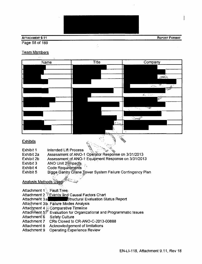
Team Members
Exhibits
Exhibit I Intended Lift ProcessExhibit 2a Assessment of ANO-l Operator Response on 3/31/2013Exhibit 2b Assessment of ANO-1 Equipment Response on 3131/2013Exhibit 3 ANO Unit 2 •mpacts-,Exhibit 4 Code RequirementsExhibit 5 Bigge .Gantry Crane Tower System Failure Contingency Plan
Analysis Methods Used.
Attachment 1 FaultTree'Attachment 2 Events,, , nnd Causal Factors ChartAttachment 3 a tructural Evaluation Status ReportAttachment 3 b. Failure Modes AnalysisAttachment 4 Comparative TimelineAttachment,5 Evaluation for Organizational and Programmatic IssuesAttachment 6 Safety CultureAttachment 7 CRs Closed to CR-ANO-C-2013-00888Attachment 8 Acknowledgement of limitationsAttachment 9 Operating Experience Review
EN-LI-118, Attachment 9.11, Rev 18

EXHIBIT 1-INTENDED LIFT PROCESS
Page 59 of 189The swap of the Unit 1stator was planned tofollow the followingbasic flow.
A portable gantrysystem is assembledbetween the Unit 1stator and the trainbay. Stations areplaced at the south endof the gantry system.A tower is assembledat the north end of thegantry system in thetrain bay.
Te it I stator is lifted. Thepocr requires that the load ismponitoed to ensure there is not an
o d due to binding or unexpectedwh The load is level to within
specifcations,
iThe load is then transported to thetrain bay and rotated to lower into thebay.
The s rotated toalign with the train bay.
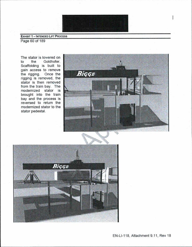
EXHIBIT 1 - INTENDED LIFT PROCESS
Page 60 of 189
The stator is lowered onto the Goldhofer.Scaffolding is built togain access to removethe rigging. Once therigging is removed, thestator is then removedfrom the train bay. Themodernized stator isbrought into the trainbay and the process isreversed to return themodernized stator to thestator pedestal.
EN-LI-118, Attachment 9.11, Rev 18

Exhibit 3131/2013
Summary Assessment of Crew Performance
The Unit 1 operating crew effectively responded to the event on 3/31/13 with thefollowing key results:
" Decay Hear Removal (DHR) function was restored within five minutes
" Spent Fuel Pool (SFP) cooling function was restore in a timely manner with less
than 30F rise in SFP temperature
" Emergency medical response was initiated in a timely manner and effectivelycoordinated
Crew response was aided by the presence of additional licensed personnel• who were inthe control room as planned for support of the refueling outage. Theseoperatorsassisted with the medical emergency procedure, ERO, , interface, station logmaintenance, etc.
The Shift Manager remained in his oversight role and exercised his responsibilitythroughout the event. He appropriately used the' team, including ERO and outagesupport personnel, to respond to the event. The CRS maintained command and controland used transient briefs throughout the day to maintain priorities and alignment.
Key Actions and Related Procedures
1. Restoration of Decay Heat Removal pert-OP-1203.028, Loss of Decay Heat
Removal
Decay Heat Removal function was restored in accordance with (lAW) Section 6.0of OP-1203.028, Decay Heat Pump Trip. The protected red train was placed inservice first with P34A•bDHRk pump started at 07:53:51 and DHR flow initiated at07:55:49.
As a backup to P34A, P346 DHR pump was started at 08:05:17 with DHR flowestablished atO08:066:110.
The- order for containment closure was initiated by the Shift Manager andappropriately' resbinded after DHR was restored.
" DHR was established in a timely, controlled manner lAW the Abnormal OperatingProcedure with no anomalies noted.
2. Response for Loss of Offsite Power Source to 4160V Electrical Buses per EOP-
1202.007, Degraded Power.
Proper automatic system response was verified per EOP-1202.007. Thisincluded verifying EDG operation per Repetitive Task 21, verifying cooling flow tothe EDGs, verifying auto-start of Service Water pumps, and aligning feederbreakers to non-vital switchgear in Pull-to-Lock status.
61

Exhibit 2a - Assessment of ANO-1 Operator Response on 3/31/2013
At the time of the event, electrical alignments were in progress to supportplanned activities for the Green Train maintenance window of 1R24. Theseresulted in the following initial conditions:
a. A2 4160 V bus was de-energized
b. A3 and A4 4160 V buses were initially cross-tied
c. B5 and B6 480 V buses were cross-tied
d. D06 Green Train battery had been disconnected from D021bus
e. D04B battery charger was supplied from Swing MCC B56 to providepower to Green Train DC bus D02 during the Green Train outage. B56was aligned to B5 at the time of the event.
Following the event, actions were taken to restore normal electrical alignment.These included re-connecting the green train, battery and restoring normalalignment for B5 and B6 vital 480V buses. The cross4t1e'between A3 and A4switchgear automatically separated on an undervoltage signal.
Response to loss of offsite power was performed in a timely, controlled mannerlAW the applicable procedures with noanomalies noted in operator performance.
3. Response to loss of spent fuel pool cooling) per AOP-1203.050, Loss of SpentFuel Pool Cooling
Response to loss of SFP cooling was performed lAW AOP-1 203.050. Spent fuelpool cooling flow was re-established at 0813 when P40B SFP Cooling Pump wasstarted. Intermediate Cooling Water Flow was momentarily established atapproximately 0930.after an offsite power source had been connected andestablished for longer term"operation approximately one hour later at 1030. From0749 to 1043, Spent Fuel Pool temperature rose approximately 2.80F from87.0°F to a peak of 89.8*F.
Power to P33C ICW pump was restored via a planned Temporary Modificationthat-rovided power from an offsite source unrelated to the Al and A2 4160VSwitchgear damaged in the event.
The delay between 0930 and 1030 in restoring ICW flow was the result ofvariation in ICW surge tank levels observed when P33C was initially started. Thiswas attributed to repositioning of ICW Suction and Discharge cross-connectvalves on loss of Instrument Air. The crew chose to maintain the ICW pump idleuntil the two ICW loops could be cross-connected at both the suction anddischarge headers for the ICW pumps. This configuration was established withinapproximately one hour and long term SFP cooling capability was then restored.
The planned temporary alteration providing diverse power to the ICW pumpsproved very useful in restoring Spent Fuel Pool cooling. SFP cooling was
62
I
Exhibit 2a - Assessment of ANO-1 Operator Response on 3/3112013
established in a timely and controlled manner with less than 30F rise in SFPtemperature.
4. Fire Water Leak
When the fire water leak was reported to the control room, the Shift Manager andCRS appropriately decided to depressurize the fire water system. O'jperatorswere dispatched to the Intake Structure to secure the fire water pumpslocally.While at the intake the operator successfully secured the diesel driven fire waterpump but later recognize the temporary motor driven fire water pump beigsupplied power from the London line was in operation. The temporayfire aterpump was secured at approximately 0820 hours (CR-ANO-C-2013-01072 wasinitiated to assess the timeliness of securing the temporary ,fire pump). Theaction to secure fire water was appropriate for conditions and compensatoryactions were promptly initiated to stage portable fire. water pumps and obtainassistance from the London Fire department. Technical R'quirements Manual(TRM) requirements for the fire suppression system were appropriatelyconsidered.
During the event the "At-the-Controls" (ATC) operator observed "Dirty WastePanel Trouble" alarm K09-F5 had alarmed and that the Auxiliary Building Sumplevel was high. The Waste Control Operator (WC'0) was dispatched to elevation317' and water was observed to be accumulatinglin the general area. The WCOinspected the Decay Vaults and observed no accumulation of water at that time.The WCO had previously verified that the, DH vault doors were dog closed andthe DH vault drain isolation valves ABS-13 and ABS-14 were closed. Water levelin the general area'on elevation 317' reached approximately 1.5" and stoppedrising as the fire •water pumps had been stopped. Later a comparable water levelwas observed. to have accumulated in the 'B' DHR vault. Components in theDHR vault were, not challenged by the accumulation of water; however, thiscondition did indicate probable leakage through vault isolation valve ABS-13.Water level, in the 'B, DHR vault was not sufficient to actuate the level switchassociated with K09-D4, Train B Decay Heat Room Flood, which has anactuation setpoint of approximately 1.6 inches (CR-ANO-1-2013-00824 and CR-
S:-ANO-C-201.3-01129).
5. Response to Loss of Instrument Air per AOP-1 203.024, Loss of Instrument Air
. The majority of actions dictated by the Loss of Instrument Air AOP were notapplicable for the conditions present at the time of this event. Consequences ofthe loss of Instrument air included:
a. DHR Cooler Bypass Valves CV-1432 and CV-1433 failed closedb. Pneumatic DHR pump suction temperature indications failed lowc. ICW pump cross-connect valves failed closed.
63

Exhibit 2ai- 1 3131/2013
Failure of the DHR cooler bypass valves was anticipated by the Control Roomstaff. The 'A' DHR train was aligned with the cooler bypass valve fully closedprior to the loss of instrument.
For ICW cooling, the 'C' ICW pump had been selected for operation.Consequently, a flow path for the Nuclear ICW loop existed when Instrument Airwas lost.
6. Emergency Classification per OP-1903.010, Emergency Action LevelClassification
Criteria for Emergency Action Level classification were reviewed, by the ShiftManager and peer checked by other Senior Reactor Operators present in theControl Room. No applicable criteria were identified.
7. Emergency Response/Notifications per OP-1 903.011, EmergencyResponse/Notifications K'
The Shift Manager elected to staff the ANO Emergency Response Organizationbased on the complexity of the event. ERO" staffing was initiated via voicemessage lAW OP-1903.011.
A courtesy call to the Arkansas Department, of Health and NRC OperationsCenter was performed lAW OP-1903.011 for this event of Potential PublicInterest.
8. Response to Injuries per OP-1i903.023 Personnel Emergency
Emergency medical- team was dispatched and ambulances were promptlyrequested lAW the instructions of form OP-1903.023B.
9. Response to Loss of Control Room Phones and Plant Computer NetworkNormal phone service was lost momentarily during the event. Using instructionsprovided witeh herStation Blackout procedure tab, analog phones were placed in
service and verified functional within a matter of minutes.
An extra. Reactor Operator was assigned responsibility for the station log. Whencomputer network problems affected access to the station log application, apaper log was maintained and later transferred to the electronic log.
64
I
Exhibit 2b - Assessment of ANO-1 EauiDment Resnonse on 3131/2013
Summary Assessment of Plant Equipment Response
The event had the following significant, direct impacts to plant equipment:
* 4160 VAC Switchgear Al and A2 were damaged, rendering offsite powersources from Startup #1 and Startup #2 Transformers inoperable
* 4160 VAC supply from AACDG via 2A9 Switchgear was damaged and renderedinoperable
* Firewater lines in the train bay were severed, requiring that fire water purhps besecured
* Instrument Air header pressure was lost when shared source from Unit 2degraded due to the loss of 2A2.
* Key safety systems functioned as designed with the, following highlights:
* Both Emergency Diesel Generators automatically started and tied to theirrespective bus
" Service Water pumps automatically.,started and restored header pressure asdesigned .
Both trains of DHR responded as designed when placed back in service
Equipment necessary to support Spqnt Fuel Pool cooling operated as necessary torestore SFP cooling with lessthan 30F rise in SFP temperature.
Sealing pressure to the nozzle dams on the lower Steam Generator manways slowlylowered after power was lost, to associated support equipment. Compensatory actionswere taken to provide an alternate means of pressurizing the seals. (CR-ANO-1-2013-00830).Water ingress was :noted in"the vault for the B train of DHR equipment indicatingprobable leakage through the associated drain isolation valve (CR-ANO-1-2013-00825).Water did not leak, into the vault for the A train of DHR.
Sysstem Level, Review
1.: Electrical System
At the time of the event, electrical alignments were in progress to support plannedactivities for the Green Train maintenance window of 1R24. These resulted in thefollowing initial conditions:
* A2 4160 V bus was de-energized
* A3 and A4 4160 V buses were initially cross-tied
65

Exhibit 2b - Assessment of ANO-1 Equipment Response on 3131/2013m n I
" B5 and B6 480 V buses were cross-tied
" D06 Green Train battery had been disconnected from D02 bus
" D04B battery charger was supplied from Swing MCC B56 to provide power toGreen Train DC bus D02 during the green train outage. B56 was aligned to B5 atthe time of the event.
Review of the accident video and comparison of timing between Unit 1 Loss of Powerand Unit 2 Reactor Trip suggests that Al Bus locked out early in the accideht sequence,perhaps when the stator first impacted the turbine deck.
After Al locked out, EDG #1 properly started and achieved rated voltage and frequencywithin 15 seconds. On the other hand, starting of EDG #2 was delayed as no DC powerwas present for associated relaying and control components. This was expected for theconfiguration with D06 battery disconnected for replacement.Once•power was restoredto DC bus D02 via charger D04B, EDG #2 started and provided power to associatedcomponents.
2. Service Water
Service Water components functioned as designed with no anomalies noted.
3. Decay Heat System
DHR components functioned as designed with one minor anomaly noted. A fewhours after initiation of the event, the Low Pressure Injection flow indicator for LoopA DHR/LPI failed low: (CR-ANO-1-2013-00830)
4. Steam Generator Nozzle Dams
As documented in CR-ANO-1-2013-00830, sealing pressure for the SteamGenerator nozzle dams slowly lowered after loss of power to support equipment.Compensatory actions were taken to provide an alternate means of maintainingsealing gas pressure.
5. Spent Fuel Pool Cooling and Intermediate Cooling Water
Spent Fuel Cooling Pumps, which are powered from vital buses 85 or B6, functionedas designed. Intermediate Cooling Water was restored through use of a plannedTemporary Modification which provided power from an unaffected off-site source.P33C was selected as the pump to receive temporary power due to its associationwith the Nuclear ICW loop.
During restoration of Intermediate Cooling Water, variation in ICW surge tank levelswas noted when P33C 1CW pump was initially started in Single Loop, Single Pump
66

Exhibit 2b - Assessment of ANO-1 Equipment Response on 3/31/2013
mode of operation (cross-connect valves closed due to loss of Instrument Air). Thisindicated possible leak by associated cross-connect valves (CR-ANO-1-2013-00912). Once Instrument Air pressure was restored and ICW loops were cross-tied,stable surge tank level was observed.
6. Auxiliary Building
Leakage into the Auxiliary Building was noted as documented in CR-AN 1-23-00824. No adverse equipment consequences were noted as result Qfthi ak .Additionally, leakage into the 'B' Decay Heat Vault was noted as doumt CR-ANO-1-2013-00825, indicating probable leakage past vault drain isa n valveABS-1 3.
7. Components Supported by Instrument Air
When Instrument Air pressure was lost, compon rJesponded as expected.Noteworthy impacts included:
a. DHR Cooler Bypass valves failed dosed,,rb. ICW Pump Cross-Tie Valves Failed Closedc. Pneumatic DHR Pump Suction Te tu icators failed low.
Se wr sys-eS4.ww100,
............................ ... ...... i
o ... .3 .........
w 1
*~~~v~~**~ $14 Y~V oq4fl a z.r; , .
67

I
Exhibit 2b - Assessment of ANO-1 Equipment Response on 313112013
041 Syo= Pww*Ct - 5 Itý fte .
... .. ... .... .. .
.V......
~I
1iiamt_ MlI
I - *~, , ~ * 9 4914 ~ y14 ~14to
~
~9~tAr tr9>9 '~t29A 29VW*<49CA. A99P9 A9W* ~;~99' *
014 st- pao*
12$ .4*KO 1123
f!"s z~
:1
4--45
ý 7 Zý
31 "WI~-:~4~9 ~o,
-. "9 z, % - .
4'
68

I
Exhibit 2b - Assessment of ANO-1 Equipment Response on 313112013
ORC"W~IW svo"Pm Rle" •,
120
30, low,07ý49:0031-Mý2011
32. .. ....
Z'.W.~ -----
40 16" .
70, qo ------..... T....
enA -r.. tA-il* V4~t4 -q- - 03 UI I
, ~ I v.e VM Mg
69

Exhibit 2b - Assessment of / on 313112013
ICW Systam Opef~tvAk
J 4
40¸
07.Mo10 0,ý0
y *.*~ ~ As9I~r4 ID
v* ft %I ** V. V. M
70

This assessment was performed to evaluate the ANO-2 response to the U1stator drop event on 3/31/13. This event was a challenge to the operators andwas successfully navigated without major issues identified in the operations teamperformance. A summary of the emergency/abnormal procedures implementedduring the event and recovery include:
• Standard Post Trip Actions
Reactor Trip Recovery
Loss of Instrument Air
Personnel Emergency
* Fire Water Main Rupture response
* Spent Fuel Pool Emergencies
" Emergency Plan
" Fire and Explosion
" Natural Circulation
The following provides a lis~t of the rmajor, challenges and activities that werepresent throughout the day. ,tThisiassessment starts at the time of the U2 planttrip and extends through the end ofshift brief,(1830). Each of the following itemsare addressed in further detail in CR-ANO-2-2013-00903 CA-1.
* U2 reactor trip due to 'B' RCP breaker tripping. on motor differentialrelay (vibration) as a result of the stator impact to the U2 turbine-building struc~ture.'
" Firewater turbine building main ruptured in the train bay
* Personnel Emergency procedure entered,\ 'Standard post trip actions (SPTA) implemented and compensatory
actions taken for 'A' Main Feedwater Regulating Valve (MFRV) Failure.Running Main Feedwater Pump (MFP) tripped and EmergencyFeedwater Actuation System (EFAS) actuated.
* Response to fire water spraying on plant equipment
* Control Room (CR) isolation due to rad monitor (RI-8001) actuation -manually placed CR on emergency recirculation
• Secured. 2P-7A and 2P-7B Emergency Feedwater (EFW) Pumps (T.S.3.0.3 entry) to support placing Auxiliary Feedwater (AFW) Pump inservice
71

I
Exhibit 3 - ANU unit z impacts
" Reset EFAS and restored 2P-7B to standby. Remained in T.S. 3.7.1.2for throttling EFW injection motor operated valves (MOVs) using AFW
" SU#3 Lock out due to 2A1 13 (SU#3 feed to 2A1) as a result of phaseto phase fault in the feed to the 2A1 bus
o 2A2 de-energized and 2A4 powered from the #2 EDG. 2A1 and2A3 slow transfer to SU#2.
o 2H1 and 2H2 de-energized. RCPs and Circulating Water Pumpsecured
o AFW Pump tripped on SU#2 load shedo Loss of Spent Fuel Pool (SFP) cooling due to2P,40B tBVi•o Re-entered SPTAso Entered fire and explosion AOPo Entered Natural Circulation AOPo Entered Loss of Instrument Air AOP
" Letdown isolated, Normal Pressutizer Spray not available, SteamDump Bypass Control System "(SDBCS) unhavailable, Running CCPtripped, RCS level rising -;Pressurizer Heaters energized and RCSheated up
* Manually actuated,'EFAS when AFW pump tripped" Re-started instrument air compressor (header pressure would only
maintain 45 psi)" ControlRoom phones unavailableý.v t , W ";.'," Significant water'hammer on east turbine deck due to low instrument
air pressure and valves cycling" ;Momentary 4. osis of Safety Parameter Display System (SPDS) and
Plant!Computer Display in CR*. Cross tied non-vital buses 2B1 and 2B2 to allow start of the 2nd
...instrument air compressor header pressure raised to 90 psi' Started 2P-40A SFP cooling pump. Declared Notification of Unusual Event (NUE) (HU-4) based on minor
explosion damaging plant equipment. Visible damage to back of2A1 13 observed.
The operator response to the event was effective with actions taken to maintain theplants in a safe and stable condition despite the challenges associate with the liftassembly failure, medical response for injured personnel and the challenges associatedwith degraded power condition. All safety systems performed as designed aiding theoperators in the event recovery.
72

Exhibit 4 - Code Requirements
Material Handling Program
Applicable Codes per EN-MA-119
73

••..
V.
74
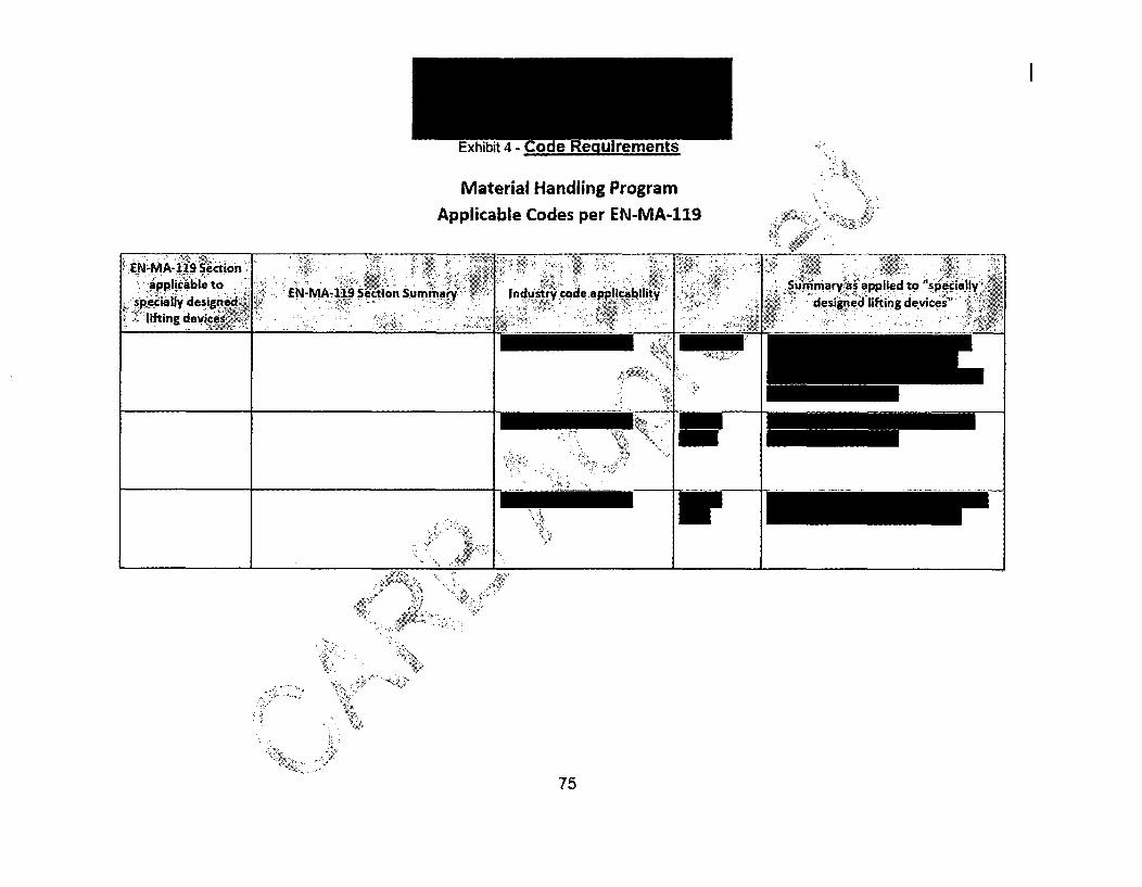
Material Handling ProgramApplicable Codes per EN-MA-119
75

I
Exhibit 5 - Bigge Gantry Crane Tower System Failure Contingency Plan
76

I
Exhibit 5- Bigge Gantry Crane Tower System Failure Contingency Plan
77

78

79

80


83

V N4
I
N
V t
r77*
~%
7*7'
N'
4
84

I
Attachment 2 -Events and Causal Factors Chart
85

I
~A'
t
N
"¾.
N<V.
#W N~>N
N>
4 /
86

Attachment 3a - Structural Evaluation Status Reportv
87

I.
Attachment 3a Atructural Evaluation Status Report
88

Attachment 3a - ý tructural Evaluation Status Report

I
Attachment3a Aructural Evaluation Status Report
90

Attachment 3a
91

;tructural Evaluation Status Report
.92

I
=; •
93

.;•
94
I
Anacr-ment.5o - i-atiure imaes Anaiysis
ATTACHMENT 9.1 FAIL'URE MODE ANALYSIS WORKSHEET
Problem Statement: On March 31, 2013, the temporary lift assembly collapsed while moving the generator stator to the train bay.

96

- rajiure ivioues ,tliaiysis
97
I
Attachment 3b - Failure Modes Analysis
m
/
98

\ /
I99

I
Attachment 3b - Failure Modes Analysis

I
101
.7

I
¾ 4
N4
*-
'V
103

Attachment 3b - Failure Modes Analysis
104

Attachment 3b - Failure Modes Analysis
1U

I
Attachment 3b - Failure Modes Analysis .
". N'•, •.•
t • ... .... .
N 7 i . , .. . . . :
106

Attachment 3b - Failure Modes Analysis

I
- rdllUIe IVIUUcb t/Jidlybib
UI


httachment 4 - Comparative I imelini
Comparative Time Line
V
f t
7
110

I
111

112

I
Attacnment 4 - uomparanve i imeitne
113

I
114

N
115

116
I
.,-' ~:
117

Attachment 4 - Comparative Timeline
118

tP'.\.
119
Anracment 4 - uomparaiive i imeiine

Attachment 4 - Comparative Timeline
121

Attacflment 4 - uomparative I imeline <1
122

I
123

I
~. yr
)1'V
124

I
Attachment 4 - Comparative Timeline
125

I
/-uacnmeni -4 - uomparative i imeiine
/
126

I
2*~.
127


129

Attachment 4 - Comparative Timeline 4•* .
130

131

P)
ATTACHMENT 9.5Sheet I of 13
EVALUATION FOR ORGANIZATION & PROGRAMMATIC ISSUES
General Guidance
It is not the intent of this activity to perform a "global" (i.e., site- or system-wide) searchfor O&P issues (LOWs). The scope of this activity should be limited to the event bleinginvestigated. If this evaluation is being performed for an Apparent Cause Evaluation,then substitute the term "root" with "apparent" and "RCE" with "ACE".
The questions below are intended to guide an evaluation for "local" O&Plissues (LOWs)- that is, those O&P issues (LOWs) which influenced the outcome of the event underinvestigation. They represent the failure modes of the involved Organizations andimplementing Programs (i.e., work processes).
The identified O&P factors shall be either causes or new adverse conditions requiring acondition report.
" The organization is not usually aware of their potential for influencing an event.
" They are typically EXTERNAL to the observed behaviors.
Since root cause investigation is a discoveryiprocess"(a strongly knowledge-basedactivity, i.e., "you don't know what you don't know), this step serves as a valuable "tool"for the Evaluator (or team), to be used during the development of the causes.
This evaluation should typically be performed as part of the "Analyze" portion of theprocess.
For this process to be most effective, it is important that all the organizations andprograms (work processes) which-,interacted during the event are known.
The Organizational aindProgramm tic qualified individual should provide oversight andcoaching as necessarý during- the process.
Process
The root cus-e evaluator (or team) performs each of the following steps:
1. ,:Screen each of the five failure mode areas to determine if the applicable causalfactors maybe related to the event. Based on the results of the determination, use
.:,the O&P questions below to identify whether any causal factor indicates thepresence of organizational or programmatic weaknesses.
2. Initiate documentation for any identified O&P issues (LOWs) that do not appear tohave a "cause & effect" relationship to the investigated event - initiate a new CR.
3. Document the results of this evaluation (including a brief summary of supportingfacts) for each of the failure modes that apply in the Organizational andProgrammatic Weakness Evaluation section.
132

I
Attachment 5 - Organizational and Programmatic Analysis (O&P)
a. For any O&P causal factors identified as contributing to the event discusshow this factor is related to the appropriate cause.
b. Discuss any identified O&P issues (LOWs) that do not appear to have a"cause & effect" relationship to the investigated event. Document the new CRinitiated.
c. Ensure failure modes that apply are evaluated and documented in this.section.
133

Attachment 5 - Organizational and Programmatic Analysis (O&P)
ATTACHMENT 9.5 EVALUATION FOR ORGANIZATION & PROGRAMMATIC ISSUES
Sheet 2 of 13Becilnninci of Form
Attach this Worksheet to the Disposition CA in PCRS if not incorporated in the RCE.The questions are provided to promote consideration of like symptoms, not to define aspecific failure mode. O&P causal factors are symptoms of the more basic causes ofthe event and are typically an action or condition that shaped the outcome of the..situation.For each causal factor block checked YES:
1. Ensure it is appropriately represented in the WHY Staircase as a causle orcontributor.
2. In the BARRIER ANALYSIS, tie the O&P causal factors as appropriate toBarriers that failed, were weak, missing, or ineffective 1 ,
3. Summarize in the O&P section of the report how the identified Organizational &Programmatic weaknesses caused or contributeto the event and identify theBarrier which should have prevented it.
134

Attachment 5 - Organizational and Programmatic Analysis (Q&P)
4 A . ,- :
. .. .
,: ;
A ,"
...' .. N•.
7• ••
,,..... . • ,135i
A-,'11•

P"%LLdL:$•I tl I!I~I•:lIL J4I F I V,,JI lIII..lUU I IIOU /-I'JI la ia,! k t,:l Jl •
ATTACHMENT 9.5 EVALUATION FOR ORGANIZATION & PROGRAMMATIC ISSUES
136

Attachment 5 - rganizational and Programmatic Analysis (O&P)
EVALUATION FOR ORGANIZATION & PROGRAMMATIC ISSUESATTACHMENT 9.5Sheet 4 of 13
137
I
A
A
* AWr
A
4
138

Attachment 5 - Organizational and Programmatic Analysis (O&P)
ATTACHMENT 9.5 EVALUATION FOR ORGANIZATION & PROGRAMMATIC ISSUES
Sheet 5 of 13
139

AttachP (O&P)
140

Attachrr I&P)
ATTACHMENTSheet 7 of 13
).5 EVALUATION FOR ORGANIZATION & PROGRAMMATIC.ISSUES
141
Attachment 5 - Organizational and Programmatic Analysis (O&P)
•* ,..
7 ½
142

Attachment 5 - Organizational and Programmatic Analysis (O&P)
ATTACHMENT 9.5 EVALUATION FOR ORGANIZATION & PROGRAMMATIC ISSUES
Sheet 8 of 13
143

Attachment 5 onal and Programmatic Analysis (O&P)
EVALUATION FOR ORGANIZATION & PROGRAMMATIC ISSUESATTAC HM ENT 9.5Sheet 9 of 13
144

Attachment 5 - Organizational and Programmatic Analysis (O&P)
ATTACHMENT 9.5 EVALUATION FOR ORGANIZATION & PROGRAMMATIC ISSUESSheet 10 of 13
• :.?:, •= • ;.':, . ,.,..
•i. i~i• ,
• 4•2/4...
145

ATTACHMENTI
Sheet 3 of 10.6 SAFETYCULTURE EVALUATION

I
siK 4 4N *>tji:./
49. <V.'~ K.>'7
/
N
.. ~ VIZ
7
147

ATTACHMENT 9.6 SAFETY CULTURE EVALUATION
148

N.
~> 7/
/ I
\ <
..>
/
149

.I
A~tacnment a - owerey Ltulure Anaiysis
ATTACHMENT 9.6Sheet 5 of 10
SAFETY CULTURE EVALUATION
151

I
¾
vi
/ At~<N,
'U'
«C
.7 '4'
C'C'
N
C~il~ 4'
152

I
153

I
Attachment 6 - Safety Culture Analysis
ATTACHMENT 9.6Sheet 8 of In
SAFETY CULTURE EVALUATION
154

ATTACHMENT I
Sheet 9 of 10.6 SAFEfY CULTURE EVALUATION
155
.I
•SAFETYiCULTURE EVALUATION;;;;_I
ATTACHMENT 9.Sheet 10 of 10
5

I
7 Nt
°•. ,,"...
,•;
'V
157

Attachment 7 - CRs Closed to CR-ANO-C-2013-C
CRs Closed to this RCE.
158,

I
159

A/UacnmTenl 0 - MCnwllOWIeUge9tit 0T 1111111
>7>7
A
>4/I
A ~-fr -~
K
160

cE feih. Zf M.F Mr.I M-M11M III$rn kwent~~ce eecod.~e oie
161

Attachment 9 - Operating. Experience Review
162

I
163

Attachment 9 - Operating Experience Review
....
164

Anacnmern u -operaung texperience
165

Attachment 9 - Operating Experience Review
I-i
166
.!
Attachment 9 - Operating. Experience Review
167

Attachment 9 - Operating Experience Review
168'

I
i•
>,
..v,
•,•.
169
I
C.
170

Attachment 9 - Operating Experience Review
171
I .
4.
I, !i ______________________________ ________
'< it • 171

Attachment 9 - Operating Experience Review
1 7 2 .......'
..
17

Attachment 9 - Operating. Experience Review
1 .3 .. .. .'.. ..
•' ! ii" ': .• .. .. ..3
achment 9 - Operating. Experience Review
<p
:1:1
I~i\ y,
174

I
illii
- uperatng. Experience Reie,
17
~i.
175

Attachment 9 - Operating Experience Review
... I .. .... :. ..... ..
I1
!17

I
A
II
-I
r
177

A .1111 lul It V - %jpvI call ly L
178

Attachment 9 - Operating Experience Review
179

I
Attachment 9 - Operating Experience Review
IIII
II
*~
It
Ii
180
Attachment 9 - Operating Experience Review
..- . U
B!'
181
Attachment 9 - Operating Experience Review
-E
182
Attachment 9 - Operating Experience Review
• I
it
i! N
18

Attachment 9 - Operating Experience Review
• .i.., .• "A
I' .,.
184

1A[LdUrZIFr1I[L Ui - IUptfiý
Im
. ... .. ., . ... . ... .
185

Attachment 9 - Operating Experience Review
....... ............... ... i
.. :::• .; ... .. ... ... ..
i• : •+. •..• •,.. Ž + .
.; +.
__ _ _ _ __ _ _ _ _
186
Attachment 9 - Operating Experience Review
..r ..... ..
187

I
Attachment 9 - Operating. Experience Review
I L1l i
188

4
189