atomic scale study of deformation and failure mechanisms in
TRANSCRIPT

10
Atomic Scale Study of Deformation and Failure Mechanisms in Ceramic-Reinforced
Metal-Matrix Composites
Avinash M. Dongare1 and Bruce LaMattina2 1Materials Science and Engineering, North Carolina State University
2Rutgers, The State University of New Jersey USA
1. Introduction
One of the long-standing problems in materials research has been the development and improvement of materials capable of withstanding ballistic/blast impact. These materials, often referred to as blast and penetration resistant materials (BPRMs), require the ability to mitigate damage and dissipate energy and momentum. These materials are designed to stop fragments and/or projectiles while preventing behind armor debris or spall. Functionally graded ceramic particle reinforced metal-matrix composites (MMCs) are an emerging class of materials that show significant promise for applications in protective structures due to their improved damage mitigation response in addition to their superior strength, stiffness and wear resistance. The improved damage mitigation is attributed to the compositional/structural gradients introduced through the variation of the concentration of the reinforcing ceramic particles (SiC, Al2O3, etc.) in the matrix [Mortensen & Suresh, 1995; Suresh & Mortensen, 1997]. These functionally graded materials show promise to reduce the need for layered structures that are susceptible to delamination and the formation of axial cracks initiated at the interface of the ceramic and the more ductile backing material. The mechanisms responsible for plastic deformation and failure of these metal-matrix composites, however, are complex and are affected by multiple factors, such as the distribution and location/size of the reinforcing particles, grain size in the metal-matrix, the structural characteristics of the interface between the particles and matrix grains, and loading conditions [Li & Ramesh, 1998, Li et al., 2007]. The design and optimization of BPRM nanocomposite materials can be significantly accelerated by improvements in the understanding of the deformation and failure mechanisms under conditions of ballistic impact. An optimized design of these materials, therefore, requires a fundamental understanding of the links between the length scales (particle size/distribution, layer thickness) and properties (structure, chemistry, etc.) of these composites that enable enabling a combination of high strength and good ductility, and improved failure resistance in impact environments. While there has been significant progress toward understanding the behavior of these materials, there are still major knowledge gaps to be filled with respect to the identification and characterization of the elementary processes responsible for plastic deformation and
www.intechopen.com
Advances in Nanocomposite Technology
228
failure. These knowledge gaps are attributed to the inability to fully integrate theory, models, and experiments because of disparate time scales and the heterogeneous nature of these materials. The time scales of the processes in these experiments can range from picoseconds to micro-seconds and the length scales can range from nanometers to micrometers [Remington et al., 2004]. These small time scales of the processes make it difficult to identify and characterize the elementary processes responsible for plastic deformation and failure using experiments alone. The molecular dynamics (MD) simulation technique has the ability to provide the atomic level structural information on the relevant micromechanisms at the time-scales of the spall experiments and may be instrumental in physical interpretation of experimental observations [Dongare et al., 2010a]. The applicability of MD simulations as an analysis/predictive tool, however, relies on the accuracy of the interatomic potentials to model the interactions between atoms in the system. The complex heterogeneity arises from the multicomponent interactions that results in complex bonding characteristics at the metal-ceramic interfaces. This heterogeniety limits the applicability of the MD technique due to inavailability of interatomic potentials capable of providing an accurate description of the structural and energy characteristics of metal-ceramic interfaces at the atomic scale. A new class of interatomic potentials referred as the angular dependent Embedded Atom Method (A-EAM) [Dongare et al., 2009a; Dongare et al., 2009b] has been recently developed that extends the ability of MD simulations to MMCs by combining the potentials conventionally used for metals with those conventionally used for ceramics in one functional form. This chapter provides an overview of the current availability of interatomic potentials to
investigate deformation and failure behavior in metal-matrix composites at the atomic scales
using MD simulations in Section 2. An in-depth discussion on the formulation of
interatomic potentials for complex metal-ceramic interactions is provided in Section 3 and
an example parameterization is provided in Section 4. The applicabilty the A-EAM is
demonstrated by investigating the strengthening and failure behavior of Si-particle
reinforced Al-matrix nanocrystalline composites at high strain rates in Section 5.
2. Interatomic potentials for Molecular Dynamics simulations
The MD simulations study the evolution of the system as a function of time using classical
atomistic models defined as interatomic potentials [Allen & Tildesley (1987)]. The
interatomic potentials, ( )1 2, ,..., NU r r r f f f
, describe the dependence of the potential energy of a
system of N atoms as a function of the positions ir f
of the atoms. The Born-Oppenheimer
approximation states that the electrons adjust to the changing atomic positions since they
move much faster than atomic nuclei. This allows the exclusion of interactions for electrons
in interatomic potentials and the potential energy can be defined based on atomic positions.
Thus, to run a MD simulation, only the details of the interatomic interactions need to be
specified in addition to the initial coordinates of the atoms in the system and boundary
conditions. This is an important advantage that enables MD simulations to be treated as
computer experiments and are therefore capable of discovering new physical phenomena or
processes like real experiments. In addition, the analysis of the results provides complete
information of the phenomena of interest at atomic-scale resolution. This predictive power
of the MD method, however, is limited by the high computational cost of the simulations,
www.intechopen.com

Atomic Scale Study of Deformation and Failure Mechanisms in Ceramic-Reinforced Metal-Matrix Composites
229
that leads to the severe limitations on time and length scales accessible for the simulation.
While the current state-of-art MD simulations boast up to 1012 atoms (~ 10 micron size cubic
samples) using hundreds of thousands of processors on one of the world-largest
supercomputers [Germann & Kadau, 2008], the duration of most of the simulations in the
area of materials research do not exceed tens of nanoseconds. The length-scales and the time
scales of the MD simulations is largely defined by the computational efficiency of the
interatomic potentials used to define the interatomic interactions. The interatomic potentials typically are analytical functions that define the energy of an atom based on the coordinates of its neighboring atoms. The parameters of the analytical functions are chosen to describe properties of the material system as observed experimentally (crystal structure, cohesive energy, density, elastic constants, phase transformations, etc.) or as predicted using ab initio simulations where experimental data is not available. Metals and metallic alloys have been studied using the embedded atom method (EAM) [Daw & Baskes, 1984; Foiles, 1985; Johnson, 1988] potentials, whereas covalently bonded systems have been studied using the Stillinger – Weber (SW) potential [Stillinger & Weber, 1985; Ding & Anderson, 1986] for Si and Ge, Tersoff potential [Tersoff, 1988a, 1988b] for Si and C, and the Brenner potential [Brenner, 1990] for hydrocarbon systems. Each of these potentials has a unique functional form and underlying physical concept that allows them to model distinguishing characteristics of the material system. For example, the EAM potential uses an embedding energy term that simulates the effect of an atom embedded in an electron density in metals. The SW potential uses an explicit angular term that stabilizes the diamond cubic lattice for Si and Ge. The Tersoff potential uses a bond order interaction (which includes an angular dependence) that defines the strength of a bond based on the surrounding environment for Si, Ge, and C. These unique functional forms and concepts limit the transferability of these potentials from metallic systems to covalent systems and vice versa and hence limits the atomistic studies to pure systems or alloys with similar bonding characteristics. The modified embedded atom method (MEAM) potential [Baskes, 1992] is an attractive potential to model mixed metal-covalent systems as it includes parameterization for many cubic metals, as well as Si, Ge, C, H, N, and O. However, the formulation uses a many-body angular screening function as a cutoff mechanism that makes the potential computationally expensive. In addition, the parameterization of the mixed cross interactions in mixed systems also requires an adjustment of the parameters of the pure components [Thijsse, 2005] that will require testing the performance of the potentials for the pure systems. The applicability of MD simulations to investigate deformation and failure micromechanisms in ceramic particle reinforced MMCs requires development of new computationally efficient interatomic potenials that are able to accurately reproduce the structural and energy characteristics of the metal matrix, the ceramic phase, as well as the metal-ceramic interface. An easier solution would be to design new alloy potentials by combining the well-established and thoroughly tested potentials developed for pure components within a unified approach. A number of studies have focused on the relationships between various potentials to justify this unified approach. For example, a potential for the Pt-C system was developed with an analytical form that reduces to the bond-order Brenner potential for C and an EAM-like potential for Pt [Albe et al., 2002]. Similar connections between the EAM formalisms and the bond-order scheme of the Tersoff potential [Brenner, 1989] and between the SW and MEAM potentials [Thijsse, 2002] have
www.intechopen.com

Advances in Nanocomposite Technology
230
been discussed. These studies suggest that despite the apparent distinctions between the functional forms and underlying physical arguments used in the description of interatomic bonding in metallic and covalent systems, a unified approach is feasible. This chapter discusses the idea of developing a unified interatomic potential for systems with mixed type of bonding is extended to combine the EAM potential for metals with the SW potential commonly used in simulations of Si [Dongare et al., 2009a] and the Tersoff potential for Si and C [Dongare et al., 2009b]. The combined Angular-dependent EAM (A-EAM) potential incorporates a description of the angular dependence of the interatomic interactions into the framework of the EAM potential to make it compatible with the SW/Tersoff potentials. The A-EAM potential retains all the properties of the pure components as predicted by the original SW/Tersoff and EAM potentials and therefore eliminates the need for extensive testing for pure systems. In addition, the scope of the potential parameterization is limited to cross-interaction between the components. An example of the parameterization of the cross-interaction in the A-EAM potential is given for the Al-Si system here to study the micromechanisms related to deformation and failure of functionally graded Si reinforced Al-matrix composites (A359 alloy). Experimentally, the as-cast Al-Si (A359) alloy consists of a dendritic microstructure containing fine Si particles (wt % ~ 9 % Si) [Li et al., 1998, 2007]. The EAM potential for Al in the form suggested in Ref. [Mishin et al., 1999] is chosen as it provides a good description of the unstable and stable stacking fault energies and the surface and grain boundary energies in Al. In addition, the advantage of this potential is in the simplicity of the functional form and the availability of parameterizations for many metals, allowing for an easy implementation for a broad range of alloy systems. For pure Si, the original parameterization of SW potential [Stillinger & Weber, 1985] is used as it has been found to provide a good description of the crystalline, liquid, and amorphous phases of Si. The choice of the EAM and SW potentials renders the A-EAM potential to be computationally efficient and also provides an accurate description of the pure systems. The functional formulation of the A-EAM potential and the parameterization for the Al/Si cross-interactions are described in Section 3 below.
3. The Angular-dependent Embedded Atom Method (A-EAM)
A unified alloy potential based on a reformulation of the EAM and SW potentials in a compatible functional form is discussed in this section. A reformulation of the conventional EAM potential into a form that includes three-body terms in the expression for the total electron density function is presented first, followed by the description of an approach for incorporation of the angular dependence compatible with the SW potential.
3.1 Reformulation of the EAM potential In the EAM potentials [Daw & Baskes, 1984; Foiles, 1985; Johnson, 1988], the energy of an atom is expressed as
1
( ) ( )2
i ij ij i ij i
E r F≠
= +∑φ ρ (1)
where rij is the distance between atoms i and j, ( )ij ijrφ is the pair energy term defined as a
function of the interatomic distance, ( )i iF ρ is the embedding energy term defined as a
function of the electron density iρ at the position of atom i, and the summation is over all
www.intechopen.com
Atomic Scale Study of Deformation and Failure Mechanisms in Ceramic-Reinforced Metal-Matrix Composites
231
atoms interacting with atom i. The electron density iρ is calculated as a sum of the partial
electron density contributions from the neighboring atoms,
( )i j ijj i
f r≠
ρ =∑ (2)
where ( )j ijf r is the partial electron density contribution from atom j at the location of atom i.
Since only interatomic distances rij are needed to calculate the energy and forces in the
system, the EAM calculations are nearly as simple and computationally efficient as the ones
with pair potentials. The lack of explicit three-body terms, however, makes the conventional
EAM inappropriate for covalently bonded materials. To make the connections to SW or Tersoff potentials and to allow for the introduction of the angular dependence of the interatomic interactions, the linear sum of partial electron density contributions in Eq. (2) can be expressed through the sum of products of partial electron densities,
12 2
( )i j ijj i
f r≠
⎛ ⎞⎡ ⎤⎜ ⎟ρ = ⎢ ⎥⎜ ⎟⎢ ⎥⎜ ⎟⎣ ⎦⎝ ⎠∑
12
( ) ( )j ij k ikk i j i
f r f r≠ ≠
⎛ ⎞⎜ ⎟= ⎜ ⎟⎝ ⎠∑∑ (3)
The sum on the right hand side of the above equation includes two-body terms with identical pairs of atoms (j = k) and three-body terms (j ≠ k) that can be separated from each other. The three-body terms can be written in the form of a sum over unique triplets of atoms (i, j, k) [Thijsse, 2002]:
12
2
,
[ ( )] 2 ( ) ( )i
i j ij j ij k ikj i j k T
f r f r f r≠ ⊂
⎧ ⎫⎪ ⎪ρ = +⎨ ⎬⎪ ⎪⎩ ⎭∑ ∑ (4)
where in the first (two-body) term under the square root, the summation is over all atoms
interacting with atom i, and in the second (three-body) term under the square root, the
summation is over all pairs of atoms j and k that form unique triplets with atom i. This
formulation includes an explicit dependence on triplets of neighboring atoms and, as shown
in Section 3.2, allows for incorporation of the angular dependence of the interatomic
interactions in a form compatible with SW potential. Alternatively, the three-body terms can
be written in a form of the “bond order” dependence:
12
2
,
[ ( )] ( ) ( )i j ij j ij k ikj i j i k i j
f r f r f r≠ ≠ ≠
⎧ ⎫⎪ ⎪ρ = +⎨ ⎬⎪ ⎪⎩ ⎭∑ ∑ ∑ (5)
This formulation can be used to design an angular-dependent EAM potential compatible with the Tersoff potential [Dongare et al., 2009b].
3.2 Reformulation of the SW potential The energy of an atom in a system described by SW potential [Stillinger & Weber, 1985] is defined as
www.intechopen.com

Advances in Nanocomposite Technology
232
2 3,
1( ) ( , , )
2i
i ij i j kj i j k T
E U r U r r r≠ ⊂
= +∑ ∑ f f f (6)
The potential consists of a two-body (U2) and a three-body (U3) term, with the summation of the three-body terms being taken over all atom pairs j and k that form unique triplets with atom i. The two-body term has a Lennard-Jones form terminated at a distance rc by a cut-off function:
2( ) exp
p qij ij
ijij c
r rU r A B
r r
− −⎡ ⎤ ⎡ ⎤⎛ ⎞ ⎛ ⎞ σ⎢ ⎥= − ⎢ ⎥⎜ ⎟ ⎜ ⎟⎜ ⎟ ⎜ ⎟⎢ ⎥σ σ −⎢ ⎥⎝ ⎠ ⎝ ⎠ ⎣ ⎦⎣ ⎦ (7)
The three-body term is defined as
23( , , ) exp (cos 1 / 3)i j k jik
ij c ik c
U r r rr r r r
⎡ ⎤γσ γσ= λε + θ +⎢ ⎥− −⎢ ⎥⎣ ⎦f f f
ij c ik cfor r r , r r< < (8)
were θjik is an angle between vectors ijrf
and ikrf
originating from atom i and directed to
atoms j and k. The parameters A, B, p, q, λ, ε, σ, ┛, and rc are adjustable parameters that are
chosen to reproduce the properties of crystalline, liquid, and amorphous phases, as well as
surface structures for Si. The sum of the three-body terms in Eq. (8) can be rewritten in a
form of embedding energy,
23 2
,
( ) ( , , )2( )
i
i i i j k iSij k T e
F U r r rf⊂λερ = = ρ∑ f f f
(9)
where the electron density and partial electron density contributions are defined as
12
2
,
2 ( ) ( )(cos 1 / 3)i ij ij ik ik jikj k T
f r f r⊂
⎛ ⎞⎜ ⎟ρ = θ +⎜ ⎟⎝ ⎠∑ (10)
( ) expSiij ij e
ij c
f r fr r
⎛ ⎞γσ⎜ ⎟= ⎜ ⎟−⎝ ⎠ (11)
where Sief is an adjustable parameter that cancels out in Eq. (9) for pure Si. Note that in the
expression for the electron density given by Eq. (10), the partial electron density
contributions are defined by the type of the atoms forming the bond, ( )ij ijf r , rather than the
type of the neighboring atom, ( )j ijf r , as in the original EAM, Eq. (2). This notation allows
the definition of electron density contributions to be different for a bond formed by mixed
species. In addition, the definition also allows for the incorporation of complex effects such
as a charge transfer between species by defining different contributions to the electron
density from two interacting atoms at the locations of these atoms, i.e. ( ) ( )ij ij ji ijf r f r≠ for
atoms i and j of different type [Dongare et al., 2009a]. This definition provides more
flexibility in fitting the potential to the experimental data and the results of ab initio
www.intechopen.com

Atomic Scale Study of Deformation and Failure Mechanisms in Ceramic-Reinforced Metal-Matrix Composites
233
calculations, as discussed in Section 4, where an example of the parameterization procedure
for cross-interactions is given for Al-Si system.
3.3 Angular-dependent EAM compatible with SW potential The reformulation of the three-body term of the SW potential in the functional form of the
EAM embedding function, Eq. (9) with the inclusion of the first (two-body) term under the
square root in Eq. (4) can be used to wite a combined electron density as
( ) 12
2
,
(1 ) ( ) 2 ( ) ( )(cos 1 3) i
i
ci i ij ij ij ij ik ik jik
j i j k T
f r f r f r≠ ⊂
⎧ ⎫⎪ ⎪ρ = − δ + θ +⎨ ⎬⎪ ⎪⎩ ⎭∑ ∑ (12)
Two parameters, ├i and ci, are added to ensure that the combined electron density given by
Eq. (12) reduces to the conventional EAM potential for pure metals and to the original SW
potential for pure Si. For metals, ├i = ci = 0 excludes the angular dependence and includes
the radial contributions to electron density, thus, yielding the original EAM potential. For Si,
├i = 1 and ci = 2 transform the electron density function into the three-body function of the
SW potential, Eq. (10), that retains the angular dependence. The combined potential that
reduces to the conventional SW and EAM potentials for pure components can be then
formulated:
( ) 12
2
,
1( ) (1 ) ( ) 2 ( ) ( )(cos 1 3)
2i
i
ci ij ij i i ij ij ij ij ik ik jik
j i j i j k T
E r F f r f r f r≠ ≠ ⊂
⎡ ⎤⎧ ⎫⎪ ⎪⎢ ⎥= + − + +⎨ ⎬⎢ ⎥⎪ ⎪⎩ ⎭⎢ ⎥⎣ ⎦∑ ∑ ∑φ δ θ (13)
Here, the form of the two-body term of the SW potential, φij(rij) = U2(rij). As will be discussed
in the next sections, the parameterization of the A-EAM potential for Al-Si interactions does
not require an angular dependence of the electron density function for metal atoms. As a
result, the computational efficiency of the evaluation of the A-EAM potential can be
improved by rewriting the total electron density function in a form that does not involve the
summation over triplets of neighboring atoms around a metal atom:
2
,
1( ) (1 ) ( ) ( ) ( )(cos 1 3)
2
i
i
n
i ij ij i i ij ij i ij ij ik ik jikj i j i j k T
E r F f r c f r f r≠ ≠ ⊂
⎡ ⎤⎧ ⎫⎪ ⎪⎢ ⎥= + − + +⎨ ⎬⎢ ⎥⎪ ⎪⎩ ⎭⎢ ⎥⎣ ⎦∑ ∑ ∑φ δ θ (13a)
Similarly to Eq. (13), the parameters are set to ├i = ci = 0 for metals (the triplet contribution to
electron density is eliminated) and ├i = 1 and ci = 2 for Si (the radial contribution to the
electron density is eliminated). The additional parameter ni is equal to 1 for metals and 1/2
for Si. While in this work we use the formulation of the A-EAM potential given by Eq. (13a),
the alternative formulation of Eq. (13) is useful when an angular dependence needs to be
included in the electron density of metal atoms in order to provide an adequate
representation of the interatomic interactions in metal-Si alloys.
The functional form and parameters of the embedding energy functions, ( )i iF ρ , as well as
the pair energy and partial electron density functions for the interactions between atoms of
the same type are directly defined by the original EAM and SW potentials and do not need
www.intechopen.com

Advances in Nanocomposite Technology
234
to be adjusted in the alloy potential. The fitting of the alloy potential, therefore, is limited to
finding the optimum parameters for the pair energy term, ( )ij ijrφ , and the partial electron
density contributions, ( )ij ijf r , for cross-interactions between atoms of different type. The
angular dependence of interatomic interactions is incorporated into the alloy potential given
by Eqs. (13) and (13a) in a form that is compatible with SW potential. Thus, this potential is
referred to as the angular-dependent embedded atom method (A-EAM) potential.
4. A-EAM Potential for Si-particle reinforced Al-matrix composites
To test the ability of the combined A-EAM potential to reproduce the properties of systems
with mixed metallic-covalent bonding, in this section we provide an example of
parameterization of the potential fo Al-Si systems. The formulation of the A-EAM potential,
given by Eq. (13a), implies that the presence of a Si atom contributes to the electron density
of a neighboring metal atom only through the two-body term of the electron density
function that does not have the angular dependence. On the other hand, the presence of a
metal atom contributes to the electron density of a neighboring Si atom through the three-
body (triplet interaction) term of the electron density function.
For Al-Si cross-interactions, the pair energy term is defined as:
( ) exp expC CP Q
ij ijM Mij ij C C C C
ij M C ij M C
r rR Rr A B
r R r R
− −⎡ ⎤ ⎡ ⎤⎛ ⎞ ⎛ ⎞⎛ ⎞ ⎛ ⎞⎢ ⎥ ⎢ ⎥⎜ ⎟ ⎜ ⎟= − − −⎜ ⎟ ⎜ ⎟⎜ ⎟ ⎜ ⎟⎜ ⎟ ⎜ ⎟− −⎢ ⎥ ⎢ ⎥⎝ ⎠ ⎝ ⎠⎝ ⎠ ⎝ ⎠⎣ ⎦ ⎣ ⎦φ α βσ σ (14)
where AC, BC, ┙C, ┚C, σC, RM, PC, and QC are fitting parameters. It should be noted that the
partial electron density contributions ( )ij ijf r are defined based on type of bond i.e. Si-Si, Al-
Al, and Al-Si. The functional form for the partial electron density attributed to an Al-Si bond
is given by
( ) ( ) expAl Si Si Al Al Si Al Si Mij ij ij ij e C
ij M
Rf r f r f
r R− − − −⎧ ⎫⎛ ⎞⎪ ⎪⎜ ⎟= = −γ⎨ ⎬⎜ ⎟−⎪ ⎪⎝ ⎠⎩ ⎭
(15)
Since there are no stable AlSi alloys (in the solid phase) observed experimentally, the
parameters for the electron density function and the pair energy function for Al-Si cross-
interactions, given by Eqs. (14)-(15), are selected based on the results of DFT calculations
performed for several representative Al-Si bulk alloy structures. Since the number of the
energy and structural parameters evaluated in DFT calculations exceeds the number of the
fitting parameters, the fitting procedure is not aimed at reproducing the exact values of the
material properties predicted in the DFT calculations. Rather, the results of the DFT
calculations and the experimental data on the enthalpy of mixing of liquid Al-Si solutions
[Kanibolotsky et al., 2002] are considered together as a target in the optimization of the
overall agreement. Although several sets of parameters were obtained that provided a good
agreement (less than 10 % deviation) with DFT results, the prediction of the enthalpy of
mixing of the liquid alloy was the true test to study material behavior in extreme
environments (high temperatures, pressures, and strain rates). The final parameter set
chosen was found to provide an overall satisfactory description of the DFT results in
addition to excellent prediction of the mixing behavior of the liquid alloy.
www.intechopen.com

Atomic Scale Study of Deformation and Failure Mechanisms in Ceramic-Reinforced Metal-Matrix Composites
235
The plots of the embedding energy, the pair energy, and the partial electron density for Si (red lines) and Al (green lines) are shown in Fig. 1.(a), (b), and (c) respectively. The plots of the the pair energy functions and the partial electron density functions and are shown by the dashed blue lines in Fig. 1.(b), and (c), respectively. Thus, according to Eq. (2) and the plots in Fig. 1., the presence of Al atoms in the neighborhood of a Si atom causes a reduction in the partial electron density at the location of a Si atom and a reduced pair energy and therefore results in the weakening of the strength of the Si-Si interactions. This weakening
(a) (b)
(c) (d)
Fig. 1. Plots of the (a) embedding energy functions, (b) pair energy functions, and (c) partial electron density contributions for EAM Al (green line) and SW Si (red line) in the A-EAM formulation. The fitting of the cross-interactions is limited to the Al-Si pair energy and the Al-Si partial electron density contributions (dashed blue line) in (b) and (c), respectively. The enthalpy of mixing of liquid Al-Si alloy at 1870 K as predicted by the A-EAM potential (red line) is shown in (d) in comparison to experimental data [Kanibolotsky et al., 2002] (black line).
www.intechopen.com
Advances in Nanocomposite Technology
236
increases the tolerance of the local configuration in Si to deviations from the perfect diamond lattice structure in the presence of Al atoms. This observation is consistent with the results of recent DFT calculations which show a weakening of the Si-Si bonds at Al/Si interface [Nakayama et al., 2006]. The prediction of the experimental dependence of the enthalpy of mixing for the liquid Al-Si alloy at 1870 K by the A-EAM potential is shown in Fig. 1.(d) in comparison to that obtained using experiments [Kanibolotsky et al., 2002]. The plot shows excellent agreement of the predication using the A-EAM potential that shows a minimum of -5.36 kJ/mol at a concentration of 49 at. % Si with experimental data exhibiting a minimum of -5.4 kJ/mol at a composition of 50 at. % Si. The accurate prediction of the mixing behavior across the composition range and the overall prediction of structural characteristics and energetics from DFT calculations enables the A-EAM to predict the relevant intermixing/melting behavior at Al/Si interfaces in extreme environments such as shock loading and radiation damage. More details of the fitting procedure and a quantitative analysis of the performance of the A-EAM potential in comparison to DFT calculations is provided elsewhere [Dongare et al., 2011].
5. Deformation and failure behavior of MMCs at high strain rates
MD simulations with the newly developed A-EAM Al/Si potential are used to investigate the strengthening and failure behavior of functionally graded Al/Si composites. Experimentally, the as-cast Al-Si (A359) alloy consists of a dendritic microstructure containing fine Si particles (wt % ~ 9 % Si) [Li et al., 2007]. While it is beyond the capabilities of MD simulations to model length scales that incorporate the gradation in composition as observed experimentally, the response of the material at local regions with different compositions can be investigated individually using MD simulations. Nanocrystalline Al/Si systems with varying volume fractions of Si grains are used as the first approximations of the local microstructure in the functionally graded Al/Si alloy. The initial Al/Si nanocrystalline systems with an average grain size of 6 nm and containing 43 grains are created using the Voronoi construction method [Derlet & Van Swygenhoven 2003]. The distribution of the Si grains is chosen at random with random grain orientations depending on the desired composition of the nanocomposites. To study the effect of volume fraction, five Al/Si nanocrystalline systems are created with volume fractions of ~ 5 %, ~ 16 %, ~ 28 %, ~ 35 %, and ~40% Si. The volume fraction is defined as the percentage of Si grains in the nanocrystalline Al/Si system. To facilitate easy comparison, the nanocrystalline composites of different compositions are created with the same grain morphologies and the same grain orientations. Periodic boundary conditions are used in all the three directions. The as-created systems are first relaxed to have zero pressure, and then equilibrated at 300 K for 100 ps. The elements of the atomic-level stress tensor are calculated as
( ) ┚ ┚┙ ┙┙┚ ij i iij i
0 j
1 1σ i F r M v vΩ 2
⎡ ⎤= − +⎢ ⎥⎢ ⎥⎣ ⎦∑ (15)
where ┙ and ┚ label the Cartesian components, Ω0 is the atomic volume, Fij is the force on
atom i due to atom j, Mi is the mass of atom i, and vi is the velocity of atom i. The strain (ε) calculated here is the engineering strain and the mean stress ( mσ ) is calculated as
( ) / 3m x y zσ = σ + σ + σ (16)
www.intechopen.com

Atomic Scale Study of Deformation and Failure Mechanisms in Ceramic-Reinforced Metal-Matrix Composites
237
where xσ , yσ , and zσ are the stresses averaged over the entire system in the X, Y, and Z
directions, respectively. The common neighbor analysis (CNA) [Honneycutt & Andersen, 1987 in addition to
coordination number (CN) is used to identify local deformations in the FCC and diamond-
cubic lattice. The initial nanocrystalline Al/Si systems with an average grain size of 6 nm are
shown in Fig. 2. with the atoms colored according to the CNA/CN values. The contour for
the Al atoms colored according to the CNA/CN characterization is as follows: the green
atoms represent bulk fcc stacking, the red colored atoms represent local hexagonal close-
packed order (stacking faults), the yellow atoms represent a coordination greater than 12,
the light blue atoms represent a coordination of 12 other than fcc, and the dark blue atoms
represent a coordination less than 12. The contour for the Si atoms colored according to the
CNA/CN characterization is as follows: the purple atomsrepresent the tetrahedral bonding
in the diamond cubic lattice, the white atomsrepresent coordination greater than 4, and the
dark blue atoms represent a coordination of less than 4. The time step for all of the MD
simulation runs was chosen to be 4 fs. The temperature was allowed to evolve during the
deformation process.
(a) (b) (c)
(d) (e) (f)
Fig. 2. The initial configuration of nanocrystalline Al/Si systems with an average grain size of 6 nm and a total of 43 grains and each atom is colored according to the CNA/CN values. The compositions (volume fractions) are : (a) pure Al, (b) ~ 5 % Si, (c) ~ 16 % Si, (d) ~ 28 % Si, (e) ~ 35 % Si and (f) ~ 40 % Si.
www.intechopen.com

Advances in Nanocomposite Technology
238
5.1 Strengthening behavior of the Al/Si nanocrystalline composite
At the macro scale, the strengths of materials are typically analyzed using the commonly
used phenomenological yield criteria such as von Mises and Tresca [Hertzberg, 1996[29].
While, these criteria have been found to be appropriate to study deformation behavior in
metals under quasi-static loading conditions, recent MD simulations suggest that several
effects result in asymmetries in the tensile and compressive strengths and render these
criteria to be inappropriate under dynamic loading conditions [Dongare et al., 2010a[30] ;
Dongare et al., 2010b. As a result, the. MD simulations of uniaxial stress loading were
carried out to compute the flow stress of the composite at high strain rates. Deformation
simulations were carried out at constant strain rate by deforming the sample in the loading
direction while maintaining zero stress conditions in the lateral directions. The scaling
parameter in the loading directions is chosen so as to achieve a strain rate of 109 s-1. For each
nanocrystalline system, three deformation simulations are carried out independently for
loading in the X, Y, and Z directions to eliminate the effect of loading direction on the
orientation of the Si grains in the composite.
The stress-strain curves obtained for the composite with a volume fraction of ~ 35 % Si are
plotted in Fig. 3.(a) and (b) for loading in tension and compression, respectively. The curves
are initially linear and lie on top of each other up to the yield point, after which they start to
deviate from elastic behavior. The flow stress (σf) is defined as the peak value of the stress in
the stress-strain curve [Dongare et al., 2010b; Dongare et al., 2010c]. It can be seen from Fig.
3. that the nanocrystalline composite is stronger in compression than in tension. The flow
stress for the nanocrystalline Al/Si composite for various compositions are tabulated in
Table 1 for conditions of uniaxial tensile stress and uniaxial compressive stress loading at a
constant strain rate of 109 s-1.
(a) (b)
Fig. 3. Stress-strain curves for deformation of nanocrystalline Al/Si sample containing ~ 35 % Si grains under loading conditions of (a) uniaxial tensile stress, and (b) uniaxial compressive stress. The three curves represent the deformation in X, Y and Z directions. Here εx, εy, and εz are the engineering strains in the X, Y, and Z directions, respectively.
www.intechopen.com
Atomic Scale Study of Deformation and Failure Mechanisms in Ceramic-Reinforced Metal-Matrix Composites
239
Si Grains Flow Stress (GPa) in (Tension/Compression)
(wt. %) xfσ y
fσ zfσ av
fσ
0.00 1.750/1.835 1.689/1.846 1.694/1.536 1.711/1.739
4.65 1.665/1.851 1.718/1.901 1.737/1.859 1.707/1.870
16.28 1.493/1.738 1.572/1.741 1.530/1.785 1.532/1.755
27.91 1.848/2.166 2.113/2.294 1.926/2.258 1.962/2.239
34.88 1.801/2.173 1.896/2.211 1.812/2.139 1.836/2.174
39.53 2.049/2.411 2.171/2.456 2.042/2.451 2.087/2.439
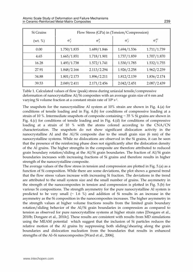
Table 1. Calculated values of flow (peak) stress during uniaxial tensile/compressive deformation of nanocrystalline Al/Si composites with an average grain size of 6 nm and varying Si volume fraction at a constant strain rate of 109 s-1.
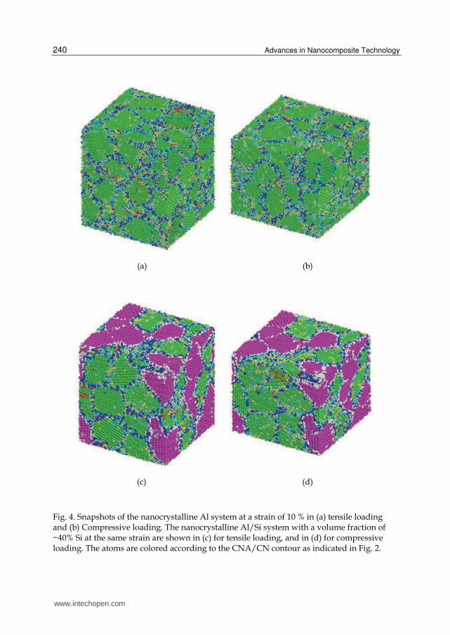
The snapshots for the nanocrystalline Al system at 10% strain are shown in Fig. 4.(a) for
conditions of tensile loading and in Fig. 4.(b) for conditions of compressive loading at a
strain of 10 %. Intermediate snapshots of composite containing ~ 35 % Si grains are shown in
Fig. 4.(c) for conditions of tensile loading and in Fig. 4.(d) for conditions of compressive
loading at a strain of 10 % with the atoms colored according to the CNA/CN
characterization. The snapshots do not show significant dislocation activity in the
nanocrystalline Al and the Al/Si composite due to the small grain size (6 nm) of the
nanocrystalline systems. While no dislocations are observed in the Si grains, it can be seen
that the presence of the reinforcing phase does not significantly alter the dislocation density
of the Al grains. The higher strengths in the composite are therefore attributed to reduced
grain boundary rotation/sliding at the Al/Si grain boundaries. The fraction of Al/Si grain
boundaries increases with increasing fractions of Si grains and therefore results in higher
strength of the nanocrystalline composite.
The average values of the flow stress in tension and compression are plotted in Fig. 5.(a) as a
function of Si composition. While there are some deviations, the plot shows a general trend
that the flow stress values increase with increasing Si fraction. The deviations in the trend
are attributed to the small system size and the small number of grains. The asymmetry in
the strength of the nanocomposites in tension and compression is plotted in Fig. 5.(b) for
various Si compositions. The strength asymmetry for the pure nanocrystalline Al system is
predicted to be very small (~ 1.6 %) and addition of Si results in an increase in the
asymmetry as the Si composition in the nanocomposites increases. The higher asymmetry in
the strength values at higher volume fractions results from the limited grain boundary
rotation/sliding behavior of the Al/Si grain boundaries in compression as compared to
tension as observed for pure nanocrystalline systems at higher strain rates [Dongare et al.,
2010b; Dongare et al., 2010c]. These results are consistent with results from MD simulations
using the MEAM potential which suggest that the inclusion of Si particles reduces the
relative motion of the Al grains by suppressing both sliding/shearing along the grain
boundaries and dislocation nucleation from the boundaries that results in enhanced
strengths of the Al–Si nanocomposites [Ward et al., 2006].
www.intechopen.com
Advances in Nanocomposite Technology
240
(a) (b)
(c) (d)
Fig. 4. Snapshots of the nanocrystalline Al system at a strain of 10 % in (a) tensile loading and (b) Compressive loading. The nanocrystalline Al/Si system with a volume fraction of ~40% Si at the same strain are shown in (c) for tensile loading, and in (d) for compressive loading. The atoms are colored according to the CNA/CN contour as indicated in Fig. 2.
www.intechopen.com

Atomic Scale Study of Deformation and Failure Mechanisms in Ceramic-Reinforced Metal-Matrix Composites
241
(a) (b)
Fig. 5. (a) Calculated flow stress curves for deformation of nanocrystalline Al/Si sample for various volume fractions of Si. The red colored curve corresponds to tensile loading conditions and the black curve corresponds to compressive loading conditions.
5.2 Failure behavior of the Al/Si nanocrystalline composite The failure behavior of nanocomposites formed by adding Si particles to Al nanocrystalline materials has been investigated using molecular dynamics simulations with the MEAM potential [Ward et al., 2006]. These results suggest that failure initiates by the nucleation of a void at the interface between the Al/Si grains. Experimental studies of deformation and failure of the A359 alloy at high strain rates also suggest that the fracture propagates along the interdendritic network of Si [Li et al., 2007]. A valid test of the A-EAM potential, therefore, is to study the micromechanisms related to ductile failure in nanocrystalline Al/Si composites consisting of an embedded Si nanocrystal in a nanocrystalline Al matrix. Deformation is carried out under conditions of uniaxial expansion (┝x = ┝y = 0, and ┝z = ┝) at a constant strain rate of 109 s-1 to relate to experimental dynamic loading conditions of dynamic failure [Dongare et al., 2009c]. Three deformation simulations are carried out independently for loading in the X, Y, and Z directions to eliminate the effect of loading direction on the orientation of the Si grains in the composite. The stresses averaged over the entire system in the X, Y, and Z direction and the are plotted in Fig. 6.(a) as a function of engineering strain (ε) for uniaxial tensile strain loading in the Z direction. The evolution of mean stress (σm) as a function of engineering strain (ε) in the loading direction is plotted in Fig. 6.(b) as obtained in the three simulation runs during uniaxial tensile strain loading independently in the X, Y, and Z directions. The stress-strain curves in Fig. 6 show three stages of deformation. The first stage corresponds to elastic deformation of the nanocrystalline system leading to a linear evolution of the curves for σx, σy, and σz up to the yield point. Continued deformation results in deviation from linearity due to GB sliding/rotation processes that are accommodated by the nucleation of dislocations [Dongare et al., 2009c]. Continued deformation results in an increase in the stress to a peak value after which, nucleation of voids results in the relaxation of stresses as indicated by a sharp drop in the stresses in the X, Y, and Z directions as shown in Fig. 6.(a).
The stress state transitions to an almost hydrostatic stress condition ( ~ ~ )x y zσ σ σ , resulting
in a sharp drop in the stress values and mean stress values until a minimum is reached.
www.intechopen.com

Advances in Nanocomposite Technology
242
(a) (b)
Fig. 6. (a) Plots of stresses in X, Y, and Z direction as a function of strain (εz) during tensile deformation under conditions of uniaxial strain at a strain rate of 109 s-1. (b) Evolution of mean stress σm during uniaxial tensile strain loading independently in the X, Y, and Z directions at a strain rate of 109 s-1.
Continued deformation results in the stress state to transition back to that corresponding to uniaxial strain. Intermediate snapshots of a section of the system are illustrated in Fig. 7. with the atoms colored according to CAN/CN contour. The snapshot in Fig. 7.(a) corresponds to a time just before the peak in the stress value (ε ~ 9.0 %). A single void is observed to nucleate at a grain boundary interface between the embedded Si nanocrystal and the neighboring Al grains in Fig. 7.(b). Also, there is relatively little dislocation activity at the GB interface between the Al/Si grains. This indicates that void nucleation cannot be attributed to a dislocation pile-up process, but rather results from the mechanical separation/sliding at the Al/Si grain boundary interface. The creation of the void is accommodated by the shearing of the nearby atoms leading to the formation of a disordered shell of atoms around the void as shown in Fig. 7.(c). Continued deformation increases the size of this shell of disordered atoms around the voids and the void shape changes to near spherical as shown in Fig. 7.(b)-(d). Although a few dislocations are observed to propagate into the grains surrounding the void, most of the material surrounding the void consists of disordered atoms and void growth is observed to occur by the shearing of the disordered regions. The creation of disordered atoms surrounding the void increases until a minima in stresses is reached in Fig. 6. This minima in stresses corresponds to the snapshot shown in Fig. 7.(e). A transition in the stress state back to that corresponding to uniaxial strain conditions results in a slower growth rate of the void that is accompanied by the recrystallization of the surrounding disordered regions. The recrystallization of the disordered region around the void is attributed to the increased temperature of the system due to nucleation and growth of the void [Dongare et al., 2009c]. The results from these MD simulations thus agree with those predicted by the MEAM potential [Ward et al., 2006] that the failure of the nanocomposite is initiated by the nucleation of the void at the Al/Si interface.
www.intechopen.com

Atomic Scale Study of Deformation and Failure Mechanisms in Ceramic-Reinforced Metal-Matrix Composites
243
(a) (b) (c)
(d) (e) (f)
Fig. 7. Snapshots of a section of the system at (a) 90 ps (εz ~ 0.09), (b) 100 ps (εz ~ 0.10), (c) 105 ps (εz ~ 0.105), (d) 110 ps (εz ~ 0.11), (e) 120 ps (εz ~ 0.12), and (d) 150 ps (εz ~ 0.15), showing the nucleation and growth of the void under conditions of uniaxial tensile strain at a constant strain rate of 109 s-1. The atoms are colored according to CNA/CN contour.
The value of the maximum mean tensile stress in Fig. 6.(b) can be compared to the peak
spall pressure during spallation experiments. The plots suggest that the spall strength
changes slightly for the nanocrystalline Al/Si composite with a change in loading direction.
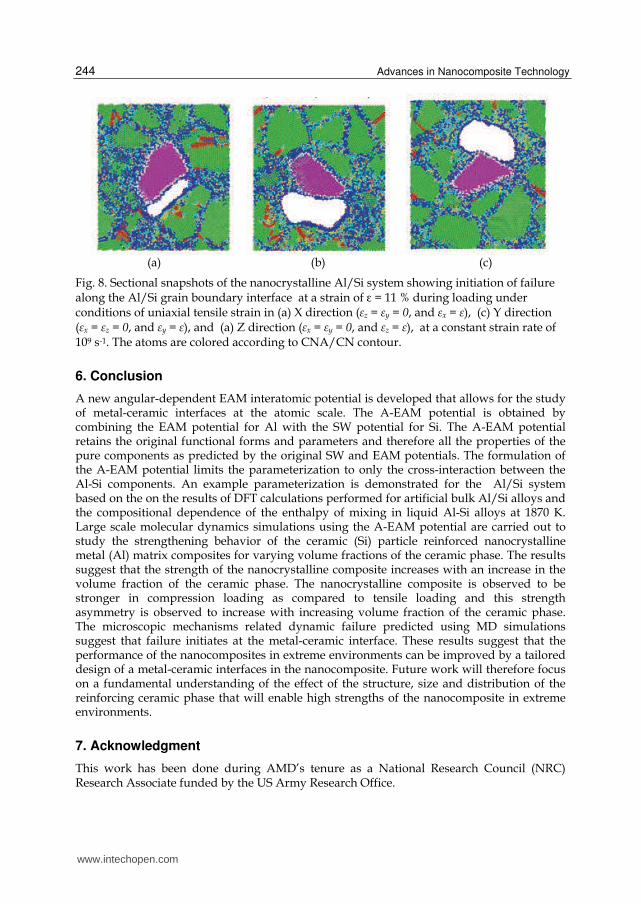
Intermediate snapshots of a section of the system at a strain of ε = 11 % during loading
under conditions of uniaxial tensile strain in the X direction, the Y direction, and the Z
direction are shown in Fig. 8.(a), (b), and (c), respectively at a constant strain rate of 109 s-1.
The snapshots suggest that failure (nucleation of void) initiates along the Al/Si grain
boundary interface. Thus, the embedding of a Si nanocrystal results in the initiation of
failure at the Al/Si interface irrespective of the loading conditions. These results suggest
that the failure resistance behavior of these metal-matrix composites is dependent on the
characteristics of the metal-ceramic interfaces in the nanocomposites. More work is needed
to be done to obtain the links between the length scales (particle size/distribution, layer
thickness) and properties (structure, chemistry, etc.) of these composites for enabling high
strength behavior and improved failure resistance so as to allow for an optimized
microstructural design of the MMnCs for use in extreme environments.
www.intechopen.com
Advances in Nanocomposite Technology
244
(a) (b) (c)
Fig. 8. Sectional snapshots of the nanocrystalline Al/Si system showing initiation of failure along the Al/Si grain boundary interface at a strain of ε = 11 % during loading under conditions of uniaxial tensile strain in (a) X direction (┝z = ┝y = 0, and ┝x = ┝), (c) Y direction (┝x = ┝z = 0, and ┝y = ┝), and (a) Z direction (┝x = ┝y = 0, and ┝z = ┝), at a constant strain rate of 109 s-1. The atoms are colored according to CNA/CN contour.
6. Conclusion
A new angular-dependent EAM interatomic potential is developed that allows for the study of metal-ceramic interfaces at the atomic scale. The A-EAM potential is obtained by combining the EAM potential for Al with the SW potential for Si. The A-EAM potential retains the original functional forms and parameters and therefore all the properties of the pure components as predicted by the original SW and EAM potentials. The formulation of the A-EAM potential limits the parameterization to only the cross-interaction between the Al-Si components. An example parameterization is demonstrated for the Al/Si system based on the on the results of DFT calculations performed for artificial bulk Al/Si alloys and the compositional dependence of the enthalpy of mixing in liquid Al-Si alloys at 1870 K. Large scale molecular dynamics simulations using the A-EAM potential are carried out to study the strengthening behavior of the ceramic (Si) particle reinforced nanocrystalline metal (Al) matrix composites for varying volume fractions of the ceramic phase. The results suggest that the strength of the nanocrystalline composite increases with an increase in the volume fraction of the ceramic phase. The nanocrystalline composite is observed to be stronger in compression loading as compared to tensile loading and this strength asymmetry is observed to increase with increasing volume fraction of the ceramic phase. The microscopic mechanisms related dynamic failure predicted using MD simulations suggest that failure initiates at the metal-ceramic interface. These results suggest that the performance of the nanocomposites in extreme environments can be improved by a tailored design of a metal-ceramic interfaces in the nanocomposite. Future work will therefore focus on a fundamental understanding of the effect of the structure, size and distribution of the reinforcing ceramic phase that will enable high strengths of the nanocomposite in extreme environments.
7. Acknowledgment
This work has been done during AMD’s tenure as a National Research Council (NRC) Research Associate funded by the US Army Research Office.
www.intechopen.com

Atomic Scale Study of Deformation and Failure Mechanisms in Ceramic-Reinforced Metal-Matrix Composites
245
8. References
Albe K., Nordlund K., and Averback R. S. (2002). Modeling the metal-semiconductor interaction: Analytical bond-order potential for platinum-carbon. Phys. Rev. B, Vol. 65, No. 19, pp. 195124 , ISSN: 1098-0121
Allen M. P., Tildesley D. J. (1987). Computer simulation of liquids, Clarendon Press, ISBN: 0198556454, Oxford
Baskes M.I. (1992). Modified embedded-atom potentials for cubic materials and impurities. Phys Rev B; Vol. 46, No. 5, pp. 2727-2742, ISSN: 0163-1829
Brenner D. W. (1989). Relationship between the embedded-atom method and Tersoff potentials. Phys. Rev. Lett., Vol. 63, No. 9, pp. 1022-1022, ISSN: 0031-9007
Brenner D. W. (1990). Empirical potential for hydrocarbons for use in simulating the chemical vapor deposition of diamond films. Phys. Rev. B, Vol. 42, No. 15, pp. 9458-9471, ISSN: 0163-1829
Daw M. S. and Baskes M. I. (1984). Embedded-atom method: Derivation and application to impurities, surfaces, and other defects in metals. Phys. Rev. B, Vol. 29, No. 12, pp. 6443-6453, ISSN: 1098-0121
Derlet P. M. and Van Swygenhoven H. (2003). Atomic positional disorder in fcc metal nanocrystalline grain boundaries. Phys. Rev. B, Vol. 67, No. 1, pp. 014202, ISSN: 1098-0121
Ding K. and Andersen H. (1986). Molecular-dynamics simulation of amorphous germanium. Phys. Rev. B, Vol. 34, No. 10, pp. 6987-6991, ISSN: 0163-1829
Dongare A. M., Neurock M., and Zhigilei L. V. (2009). Angular-dependent embedded atom method potential for atomistic simulations of metal-covalent systems. Phys. Rev. B. 80, No. 18, pp. 184106, ISSN: 1098-0121
Dongare A. M., Zhigilei L. V., Rajendran A. M., and LaMattina B. (2009). Atomic scale modeling of multi-component interactions in nanocomposites, Compos. Part B - Eng., Vol. 40, No. 6, pp. 461-467, ISSN: 1359-8368
Dongare A. M., Rajendran A. M., LaMattina B., Zikry M. A., and Brenner D. W. (2009). Atomic scale simulations of ductile failure micromechanisms in nanocrystalline Cu at high strain rates. Phys. Rev. B, Vol. 80, No. 10, pp. 104108, ISSN: 1098-0121
Dongare A. M., Rajendran A. M., LaMattina B., Zikry M. A., and Brenner D. W. (2010). Atomic scale study of plastic-yield criterion in nanocrystalline metals using molecular dynamics simulations. Metall. Mater. Trans. A, Vol. 41A, No. 2, pp. 523 -531, ISSN: 1073-5623
Dongare A. M., Rajendran A. M., LaMattina B., Zikry M. A., and Brenner D. W. (2010). Tension-Compression Asymmetry in Nanocrystalline Cu: High Strain Rate vs Quasi-Static Deformation. Comp. Matl. Sci., Vol. 49, No. 2, pp. 260 -265, ISSN: 0927-0256
Dongare A.M., Rajendran A. M., LaMattina B., Zikry M. A., and Brenner D. W. (2010). Atomic scale studies of spall behavior in nanocrystalline Cu. J. Appl. Phys., Vol. 108, No. 11, pp. 113518, ISSN: 0021-8979
Dongare A.M., Irving D. L., Rajendran A. M., LaMattina B., Zikry M. A., and Brenner D. W. (2011). Physical Rev. B, In review.
Foiles S. M. (1985). Application of the embedded-atom method to liquid transition metals. Phys. Rev. B, Vol. 32, No. 32, pp. 3409-3415, ISSN: 0163-1829
Germann TC, Kadau, K (2008). Trillion-atom molecular dynamics becomes a reality. Int. J. Mod. Phys. C, Vol. 19, No. 9, pp. 1315-1319, ISSN: 0129-1831
Hertzberg R. W. (1996). Deformation and fracture mechanics of engineering materials, 4th ed., Wiley, ISBN: 0471012149, New York (NY), USA
www.intechopen.com

Advances in Nanocomposite Technology
246
Honneycutt D. J. and Andersen H. C. (1987). Molecular dynamics study of melting and freezing of small Lennard-Jones clusters. J. Phys. Chem., Vol. 91, No. 19, pp. 4950-4963, ISSN: 0022-3654
Johnson R. A. (1988). Analytic nearest-neighbor model for fcc metals. Phys. Rev. B, Vol. 37, No. 37, pp. 3924-3931, ISSN: 0163-1829
Kanibolotsky D. S., Bieloborodova O. A., Kotova N. V. and Lisnyak V. V. (2002). Thermodynamic properties of liquid Al-Si and Al-Cu alloys. J. Therm. Anal. Calorim., Vol. 70, No. 3, pp. 975-983, ISSN: 1418-2874
Li Y., and Ramesh K. T. (1998). Influence of particle volume fraction, shape, and aspect ratio on the behavior of particle-reinforced metal–matrix composites at high rates of strain. Acta Mater., Vol. 46, No. 6, pp. 5633-5646, ISSN: 1359-6454
Li Y., Ramesh K. T., Chin E. S. C. (2007). Plastic Deformation and failure in A359 aluminum and an A359-SiCp MMC under quasistatic and high-strain-rate tension. J of Compos Mater., Vol. 41, No. 1, pp. 27-40, ISSN: 0021-9983.
Mishin Y., Farkas D., Mehl M. J., and Papaconstantopoulos D. A. (1999). Interatomic potentials for monoatomic metals from experimental data and ab initio calculations. Phys. Rev. B, Vol. 59, No. 5, pp. 3393-3407, ISSN: 1098-0121
Mortensen A., and Suresh S. (1995). Functionally graded metals and metal-ceramic composites: Part 1 Processing. Int. Mat. Rev.,Vol. 40, No. 6, pp. 239-265, ISSN: 0950-6608.
Nakayama T., Itaya S., and Murayama D. (2006). Nano-scale view of atom intermixing at metal/semiconductor interfaces. J. Phys.: Conf. Ser: 7th International Conference on New Phenomena in Mesoscopic Structures/5th International Conference on Surfaces and Interfaces of Mesoscopic Devices, Vol. 38, pp. 216-219, Maui, HI, Nov 27-Dec 02, 2005, ISSN: 1742-6588
Remington B. A., Bazan G., Belak J., Bringa E., Caturla M., Colvin J. D., Edwards M. J., Glendinning S. G., Ivanov D. S., Kad B., Kalantar D. H., Kumar M., Lasinski B. F., Lorenz K. T., McNaney J. M., Meyerhofer D. D., Meyers M. A., Pollaine S. M., Rowley D., Schneider M., Stölken J. S., Wark J. S., Weber S. V., Wolfer W. G., Yaakobi B., and Zhigilei L. V. (2004). Materials science under extreme conditions of pressure and strain rate. Metall. Mater. Trans. A Vol. 35, No. 9, pp. 2587-2607, ISSN: 1073-5623
Stillinger F. H. and Weber T. A. (1985). Computer simulation of local order in condensed phases of silicon. Phys. Rev. B 31 5262-5271, ISSN: 0163-1829
Suresh S., and Mortensen A. (1997). Functional graded metals and metal-ceramic composites: Part 2 Thermomechanical Behavior. Int. Mat. Rev., Vol. 42, No. 3, pp. 85-116, ISSN: 0950-6608
Tersoff J. (1988). New empirical approach for the structure and energy of covalent systems. Phys. Rev. B, Vol. 37, No. 12, pp. 6991-7000, ISSN: 0163-1829
Tersoff J. (1988). Empirical interatomic potential for carbon, with applications to amorphous carbon. Phys. Rev. Lett., Vol. 61, No. 25, pp. 2879-2882 , ISSN: 0031-9007
Thijsse B.J. (2005). Silicon potentials under (ion) attack: Towards a new MEAM model. Nucl Instrum Meth B; Vol. 228, Sp. Iss. SI, pp. 198-211, ISSN: 0168-583X
Thijsse B. J. (2002). Relationship between the modified embedded-atom method and Stillinger-Weber potentials in calculating the structure of silicon. Phys. Rev. B, Vol. 65, No. 19, pp. 195207, ISSN: 1098-0121
Ward D.K., Curtin W.A. and Qi Y. (2006), Mechanical behavior of aluminum–silicon nanocomposites: A molecular dynamics study. Acta Mater., Vol.54, No. 17, pp. 4441-4451, ISSN: 1359-6454
www.intechopen.com

Advances in Nanocomposite TechnologyEdited by Dr. Abbass Hashim
ISBN 978-953-307-347-7Hard cover, 374 pagesPublisher InTechPublished online 27, July, 2011Published in print edition July, 2011
InTech EuropeUniversity Campus STeP Ri Slavka Krautzeka 83/A 51000 Rijeka, Croatia Phone: +385 (51) 770 447 Fax: +385 (51) 686 166www.intechopen.com
InTech ChinaUnit 405, Office Block, Hotel Equatorial Shanghai No.65, Yan An Road (West), Shanghai, 200040, China
Phone: +86-21-62489820 Fax: +86-21-62489821
The book “Advances in Nanocomposite Technology†contains 16 chapters divided in three sections.Section one, “Electronic Applications†, deals with the preparation and characterization of nanocompositematerials for electronic applications and studies. In section two, “Material Nanocomposites†, theadvanced research of polymer nanocomposite material and polymer-clay, ceramic, silicate glass-basednanocomposite and the functionality of graphene nanocomposites is presented. The “Human andBioapplications†section is describing how nanostructures are synthesized and draw attention on wide varietyof nanostructures available for biological research and treatment applications. We believe that this book offersbroad examples of existing developments in nanocomposite technology research and an excellent introductionto nanoelectronics, nanomaterial applications and bionanocomposites.
How to referenceIn order to correctly reference this scholarly work, feel free to copy and paste the following:
Avinash Dongare and Bruce LaMattina (2011). Deformation and Failure Mechanisms in Ceramic-ReinforcedMetal-Matrix Composites at Atomic Scales, Advances in Nanocomposite Technology, Dr. Abbass Hashim(Ed.), ISBN: 978-953-307-347-7, InTech, Available from: http://www.intechopen.com/books/advances-in-nanocomposite-technology/deformation-and-failure-mechanisms-in-ceramic-reinforced-metal-matrix-composites-at-atomic-scales

© 2011 The Author(s). Licensee IntechOpen. This chapter is distributedunder the terms of the Creative Commons Attribution-NonCommercial-ShareAlike-3.0 License, which permits use, distribution and reproduction fornon-commercial purposes, provided the original is properly cited andderivative works building on this content are distributed under the samelicense.