atlas copco airline accessories - han de linea de aire.pdfyour tool is connected to your compressor...
TRANSCRIPT

9833
102
5 01
R
ecyc
lab
le p
aper
. 200
3:1.
Jet
lag
Ko
mm
200
3.
www.atlascopco.com
Atlas Copco airline accessories

Are you well connected?
A chain is only as strong as its weakest link
Your tool is connected to your compressor via an airline. Inferiorcomponents, constrictions and leaks in your airline will result inincorrect air pressure that will sabotage the performance of yourhigh quality air tools.
This will affect your productivity and cost you money in the longterm.
And it is totally unnecessary.
Atlas Copco airline accessories ensure correctair pressure under any conditions
To realize the true potential of your tool, all components in your airline should be the same high quality as the tool.
All Atlas Copco airline accessories are designed for minimum pres-sure drop. Compact, lightweight, and fully compatible they work inharmony, ensuring correct air pressure and flow under any condi-tions.
More than a century spent building air tools, has given us an exten-sive bank of criteria for designing air line accessories that guaranteethe best from the tools.
They protect your tool and prolong its life
Atlas Copco air filters remove moisture and harmful particles fromthe airline. Our regulators ensure preset secondary pressure regard-less of variations in intake air pressure and flow rate.Atlas Copco oil-fog lubricators provide lubrication where its nee-ded. Quick couplings ensure low pressure drop, plus one-hand ope-ration for fast, easy tool changing.
Our balancers take the strain off the operator
An Atlas Copco balancer means an ergonomic workstation. Thetool is virtually weightless, reducing fatigue and boosting individu-al productivity. Since the wire does not retract when the load is dis-connected, changing the tool is fast and simple.
The lightest hose on the market
Atlas Copco has a wide range of high flexible, high performancehoses for all applications. Our soft hose for air tools is up to 50%lighter than conventional hoses. You cant fail to notice the diffe-rence!
The ISO 9001 certificate – a receipt forcompany excellence
The ISO 9001 Certificate confirms that Atlas Copco Tools AB con-forms to the international rules for designing and manufacturing airand electrical handheld tools, air hoists and air motors, accordingto the Quality System Standards SS-ISO 9001; EN 29001 and BS5750:part 1.
The certificate is issued by Det Norske veritas certification AB(DNV). Det Norske veritas is an international, well establishedclassification organization accredited to perform quality systemcertification schemes according to ISO 9000.
The overall aims are: to fulfil customers expectations to deliver fault-free products and services on time to continuously improve our products and services
A huge range to choose from… and delivery isfast!
Whatever you need you will find it in our range.You can place your order with one of our authorized dealers or youcan contact us direct. Either way, delivery is fast. Our distributioncentre in Belgium guarantees that European customers can obtainany product from our basic assortment within 48 hours.
Were waiting for your call!
For complementary information: www.atlascopco.com

ContentsAIRLINE NETWORK.............................................................................. 4 – 5
BALL VALVES ............................................................................................ 6
AIR PREPARATION UNITS ..................................................................7 – 29
COUPLINGS ..................................................................................... 30 – 42
CONNECTIONS, CLAMPS, SEALS AND HOSE SAFETY VALVES..... 43 – 45
HOSES ............................................................................................. 46 – 48
SPIRAL HOSES ................................................................................ 49 – 50
BALANCERS AND HOSE REELS ...................................................... 51 – 57
TORQUE ARMS................................................................................ 58 – 63
BLOW GUNS ..................................................................................... 64 –65
INSTALLATION PROPOSALS ........................................................... 66 – 72
MIDI BAL 15 Pmax=1,6MPa
MîóI FIL 25A P
max=1MPa
MINI FIL 08B P
max=1,6MPa
A T L A S C O P C O A I R L I N E A C C E S S O R I E S 3

RUBBE
A normal compressor delivers6.8 to 7.4 bar air line pressure,depending on start and stop set-tings.
Although fulfilling importantfunctions, high performancedryers, filters and the air recei-ver can contribute a pressureloss of 0.2 0.3 bar.
AIRLINE NETWORK
To receive 6 bar at your tool you can-not accept more than 0.6 bar pressuredrop from your airline accessories.A combination of high performancecomponents and careful engineeringwill give you 0.6 bar pressure dropfrom your accessories.
For ready to use installationsplease see installation propo-sals on page 66 72.
A carefully engineered networkgives virtually no pressuredrop.
BAL and BAL-1A Ball val-ves, page 6.
MINI-B, MIDI-C and MAXI Air preparation units, page729.
Regulator
Filter
Oil fog lubricator
SPI Spiralhoses, page4950.
4 A T L A S C O P C O A I R L I N E A C C E S S O R I E S

RUBBE
RUBAIR and TURBORubber hoses, page 47.POLUR, PVC andCABLAIR Plastic hoses,page 46, 48.
Clamps,page 44.
HRIL hose reelbalancers, page56. COL Weight-
less suspensionbalancers, page51 52.
RIL balancers,page 53 55.
QIC, ErgoQIC and CLAW Couplings, page 3042.
SM Torque arms, page 5863.HM Hose reels,page 57.
Gaskets and seelings,page 44.
GUN andB2602 blowguns, page6465.
DOSOL Direct lubrication,page 2829.
Connections,page 43.
AIRLINE NETWORK
A T L A S C O P C O A I R L I N E A C C E S S O R I E S 5

VALVES – BAL AND BAL –1AAtlas Copco valves BAL and BAL-1A are suitable for air, waterand many other liquids and gases due to the choice of material.
Both are lubricated with silicone-free-grease, which is importantwhen spray-painting.
Maximum through flow full bore valve to DIN standards.
The BAL valves can be used in all settings from fully open to fullyclosed.BAL-1A is intended for operating either fully open or fullyclosed.
6 A T L A S C O P C O A I R L I N E A C C E S S O R I E S
BALL VALVES
Materials BAL1 Screw Steel a
2 Handle Enamelled aluminium b
3 Screw Stainless steel4 Cover Hot-stamped brass c
5 Seals Nitrile6 Body connector gasket Nitrile7 Ball Hot-stamped brass c
8 Body Hot-stamped brass c
Grease Silicone free
BAL
Technical data / ordering information BAL valves
Connection Working
thread Bore, D L H Weight Temperature °C pressure
Model in BSP mm mm mm kg Min. Max. bar, Max. Ordering No.
BAL 08 1/4 9.5 50 41 0.163 –20 +90 16 8202 0301 05*BAL 10 3/8 9.5 50 41 0.170 –20 +90 16 8202 0302 04*BAL 15 1/2 12.5 60 43 0.250 –20 +90 16 8202 0303 03*BAL 20 3/4 19 75 55 0.550 –20 +90 16 8202 0304 02*BAL 25 1 24.5 90 64 0.825 –20 +90 16 8202 0305 01*
Materials BAL-1A1 Screw Steel a
2 Handle Enamelled aluminium b
3 Nut Brass4 Body Hot-stamped brass c
5 Body connector gasket Teflon6 Ball Hot-stamped brass c
Grease Silicone free
BAL-1A
Technical data / Ordering information BAL -1A valves
Model Connection Working
thread Bore, D L H I Weight Temperature °C pressure
in BSP mm mm mm mm kg Min. Max. bar, Max. Ordering No.
BAL-1A 08 1/4 8 43 44 73 0.115 –30 +200 16 8202 0306 03*BAL-1A 10 3/8 10 50 47 73 0.140 –30 +200 16 8202 0306 11*BAL-1A 15 1/2 15 61 53 95 0.250 –30 +200 16 8202 0306 29*BAL-1A 20 3/4 20 70 57 95 0.360 –30 +200 16 8202 0306 37*BAL-1A 25 1 25 83 68 122 0.560 –30 +200 16 8202 0306 45*BAL-1A 32 11/4 32 100 83 150 0.950 –30 +200 16 8202 0306 52*BAL-1A 40 11/2 38 107 87 150 1.250 –30 +100 (+200a) 16 (20a) 8202 0306 60*BAL-1A 50 2 50 129 103 193 2.100 –30 +100 (+200a) 16 (20a) 8202 0306 78*
*Available directly from stock.
Illustrationin här...
1
32
5
4
6
H
L
D
l
H
L
D
a Zinc platedb Bluec Chrome-plated
1
2345
6 7
8
a Zinc platedb Blackc Chrome-plated
aWorking pressure starts to be reduced at +100°C and has reached 8 bar at +200°C.

A T L A S C O P C O A I R L I N E A C C E S S O R I E S 7
The Atlas Copco range of air preparation units includes the 1/4BSP MINI series, the 1/2 BSP MIDI series and the 1 BSP MAXIseries. The range also includes the 1/2 BSP DOSOL series and the3/4 BSP DOSOL series.
MINI, MIDI and MAXI are cubic style units which can be connec-ted within the same series using assembly kits. They consist of fil-ters, regulators, oil fog lubrication and filter/regulators.
DOSOL is a direct lubrication unit which can be used instead of anoil fog lubricator. DOSOL is mainly used when the operation timeof the tool is short and the oil needs to be present at precisely theright moment.
This air preparation chapter includes a short ordering guide inclu-ding reference page numbers for those requiring additional techni-cal information.
Below is a list of symbols used in this catalogue, with their mea-nings:
SHORT GUIDE TO AIR PREPARATION
Filter (FIL)
Regulator (REG)
Regulator (REG)Servo controlled
Regulator (REG)Panel mounting
Oil fog lubricator(DIM)
Filter/regulator(F/R)
Filter (FIL), can be supplied withvarious types of bowls, drainageand filter elements.
The normal regulator for toolapplications. The regulator iseasily adjusted using the manualcontrol. The regulator can besupplied with or without lockingfunction.
Ensures constant secondarypressure and is intended forslow fluctuating applications.
Special regulator for panelmounting.
The oil fog lubricator (DIM) isrecommended for tools withlong operation time.
The filter/regulator (F/R) unit is acombination of FIL and REG.The combination unit has lowerair flow than the individualunits.
Direct lubricator(DOSOL)
The direct lubricator (DOSOL) isrecommended for tools withshort operation times.
Catalogue symbol Description Catalogue symbol Description
Manual drainage
Semi-automatic drainage
Automatic drainage
Polycarbonate bowl
Polycarbonate bowl andbowl guard
Metal bowl
The condensate in the filter bowlis released by manually compres-sing a pair of grips.
The drainage mechanism opensautomatically when the pressure inthe bowl drops below 0.2 bar. Semi-automatic drainage can always beconverterd to manual drainageusing a kit included with the filter.
Float controlled mechanismwhich provides drainage whene-ver the condensate in the bowlexceeds a certain level. Can alsobe manually operated.
For filters and lubricators. Toughand clear plastic bowl with fullvisibility. If the polycarbonatebowl breaks, the material splitsbut does not shatter.
For filters and lubricators. As forthe polycarbonate bowl but withbowl guard as an extra safety fea-ture. Tough and clear plastic bowlwith full visibility.
For filters and lubricators. Themetal bowl has sight glasses.
Pressure gauge
For combination units gauge0–10 bar.
MîóI FIL 25A P
max=1MPa
M
SA
A

8 A T L A S C O P C O A I R L I N E A C C E S S O R I E S
SHORT GUIDE TO AIR PREPARATION UNITS
The Atlas Copco range of filters, regulators, lubricators and combi-nation units includes the following sizes: 1/4 BSP, 1/2 BSP and1 BSP thread. 1/4 BSP is the MINI-B, 1/2 BSP is at the MIDI-Cand the 1 version is the MAXI-A. All units are in metal.
The Atlas Copco range includes the direct lubrication systemDOSOL, also in metal. DOSOL is a direct lubrication system avail-able in 1/2 BSP and 3/4 BSP. The max. rec. air flow stated in theshort guide will give a pressure drop of 0.2 bar when the inlet pres-sure is 6.3 bar.
For all combination units (FD, FTD, F/RD and FRD), irrespec-tive of size gauge (R-units), mounting bracket and assembly kitswill always be included. The units are also delivered preassemb-led. Accessories have to be ordered for separate units, pleaserefer to page 16 MIN-B accessories, page 22 for MIDI-C acces-sories and page 27 for MAXI-A accessories.
Different models for various tool applications are summarized onthese pages in the form of a short ordering guide. Only the mostessential information is included. If specific technical informationis required, please consult the page reference provided.
MINI-B Pressure1/4” BSP Max. rec. Filter Type of gaugemodel air flow drainage bowl (thread)
12 l/s
MINI FIL 08B-B Ordering No. 9093 0032 11; page 11
12 l/s
MINI FIL 08B-COrdering No. 9093 0032 41; page 11
13 l/s
MINI FIL 08B-D Ordering No. 9093 0032 71; page 11
9 l/s (1/8” BSP)
MINI REG 08BOrdering No. 9093 0033 01; page 12
9 l/s (1/8” BSP)
MINI REG 08B-LPRegulator with lock pinOrdering No 9093 0073 21; page 12
MINI-P 8 l/s (1/8” BSP)
MINI REG 08P Regulator, panel mounted No. 9093 0000 31; page 13
Mounting bracketOrdering No 9090 1902 00
MINI-B Pressure1/4” BSP Max. rec. Filter Type of gaugemodel air flow drainage bowl (thread)
12 l/s
MINI DIM 08BOrdering No. 9093 0033 31; page 14
12 l/s
MINI DIM 08B-DOrdering No. 9093 0033 61; page 14
9 l/s (1/8” BSP)
MINI F/R 08B-BOrdering No. 9093 0033 91; page 15
9 l/s (1/8” BSP)
MINI F/R 08B-COrdering No. 9093 0034 21; page 15
9 l/s
MINI FRD 08B-BOrdering No. 9093 0034 51; page 14 and 15
9 l/s
MINI F/R 08B-COrdering No. 9093 0034 81; page 14 and 15
9 l/s
MINI FRD 08B-BOrdering No. 9093 0062 11; page 11, 12 and 14
9 l/s
MINI FRD 08B-COrdering No. 9093 0062 41; page 11, 12 and 14
FILT
ER
RE
GU
LAT
OR
RE
GU
LAT
OR
LUB
RIC
AT
OR
FILT
ER
/ R
EG
ULA
TO
RFI
LTE
R /
RE
GU
L. +
LU
BR
IC.
FILT
ER
+ R
EG
ULA
TO
R +
LU
BR
ICA
TO
R
50
50
~115
~140
BS
P1/4
"
BS
P1/4
"B
SP1
/4"
~92
50
22.5
50
35.5
~32
BS
P1/4
"
M 30x1.5
79
40
40
32
BS
P1/
4"
BS
P1/
4"
~97 13
6
BS
P1/4
"
BS
P1/4
"
50
50
BS
P1/4
"
~185
Ø35.5
~115
50 ~32
50
BS
P1/4
"
BS
P1/4
"
~185
145
Ø35.5
~115
50 ~32
29
SA
SA
SA
M
M
M
M
MîóI FIL 25A P
max=1MPa
M
SA
BS
P1/4
"
BS
P1/4
"~1
85
95
Ø 35,5
~115
50 ~32
29

A T L A S C O P C O A I R L I N E A C C E S S O R I E S 9
SHORT GUIDE TO AIR PREPARATION UNITS
MIDI-C Pressure1/2” BSP Max. rec. Filter Type of gaugemodel air flow drainage bowl (thread)
38 l/s
MIDI FIL 15C-AOrdering No. 9093 0008 11; page 17
38 l/s
MIDI FIL 15C-BOrdering No. 9093 0008 71; page 17
38 l/s
MIDI FIL 15C-DOrdering No. 9093 0009 31; page 17
38 l/s
MIDI FIL 15C-AEOrdering No. 9093 0008 41; page 17
38 l/s
MIDI FIL 15C-BEOrdering No. 9093 0009 01; page 17
32 l/s (1/4” BSP)MIDI REG 15C-SOrdering No. 9093 0009 91; page 18
32 l/s (1/4” BSP)
MIDI REG 15C-LPOrdering No. 9093 0073 51; page 18
MIDI-A 32 l/s (1/8” BSP)
MIDI REG 15A Regulator, servo controlled and mounting bracketOrdering No. 9093 0009 61; page 19
Gauge 0-10 barOrdering No. 9090 1172 00Assembly kit OrderingNo. 9090 2058 90
43 l/s
MIDI DIM 15COrdering No. 9093 0010 51; page 20
43 l/s
MIDI DIM 15C-DOrdering No. 9093 0010 81; page 20
43 l/s
MIDI DIM 15C-EOrdering No. 9093 0011 11; page 20
FILT
ER
RE
GU
LAT
OR
RE
GU
LAT
OR
LUB
RIC
AT
OR
MIDI-C Pressure1/2” BSP Max. rec. Filter Type of gaugemodel air flow drainage bowl (thread)
30 l/s (1/4” BSP)
MIDI F/R 15C-ASOrdering No. 9093 0011 71; page 21
30 l/s (1/4” BSP)
MIDI F/R 15C-BSOrdering No. 9093 0012 31; page 21
30 l/s (1/4” BSP)
MIDI F/R 15C-DSOrdering No. 9093 0012 61; page 21
30 l/s (1/4” BSP)
MIDI F/R 15C-AESOrdering No. 9093 0011 41; page 21
30 l/s (1/4” BSP)
MIDI F/R 15C-BESOrdering No. 9093 0012 01; page 21
25 l/s
MIDI F/RD 15C-ASOrdering No. 9093 0012 91; page 20 and 21
25 l/s
MIDI F/RD 15C-BSOrdering No. 9093 0013 51; page 20 and 21
25 l/s
MIDI F/RD 15C-BESOrdering No. 9093 0013 21; page 20 and 21
35 l/s
MIDI FD 15C-BEOrdering No. 9093 0014 11 ; page 17 and 20
35 l/s
MIDI FD 15C-BOrdering No. 9093 0013 81; page 17 and 20
43 l/s
MIDI FRD 15C-ASOrdering No. 9093 0014 71; page 17, 18 and 20
43 l/s
MIDI FRD 15C-BSOrdering No. 9093 0015 31; page 17, 18 and 20
43 l/s
MIDI FRD 15C-AESOrdering No. 9093 0014 41; page 17, 18 and 20
43 l/s
MIDI FRD 15C-BESOrdering No. 9093 0015 01, page 17, 18 and 20
FILT
ER
/RE
GU
LAT
OR
FILT
ER
/RE
GU
LAT
OR
+LU
BR
ICA
TO
RFI
LTE
R +
LU
BR
ICA
TO
RFI
LTE
R+R
EG
ULA
TO
R+L
UB
RIC
AT
OR
65
62
~165
~185
BS
P1/
2"
BS
P1/
2"
62
8827
65
~32
BS
P1/
2"
BS
P1/
2"
Ø48
Ø48
62
67.5
~
62
87.5
32
BS
P1/
2"~1
35 177
65
62
BS
P1/
2"
BS
P1/
2"
~253
~165
62 ~32
65
BS
P1/
2"
Ø48
Ø48
~253
127
Ø48
~165
62 ~32
25
BS
P1/
2"
BS
P1/
2"
Ø48
~207
127
~165
62
25
BS
P1/
2"
BS
P1/
2"
BS
P1/
2"
~253
189
~165
60 ~32
25
Ø48
BS
P1/
2"
Ø48
A
SA
A
SA
A
SA
A
SA
A
SA
SA
SA
SA
A
SA
A
SA
M MîóI FIL 25A P
max=1MPa

SHORT GUIDE TO AIR PREPARATION UNITS
MAXI-A Pressure1” BSP Max. rec. Filter Type of gaugemodel air flow drainage bowl (thread)
105 l/s
MAXI FIL 25A-BOrdering No. 9093 0018 31; page 23
85 l/s (1/4” BSP)
MAXI REG 25AOrdering No. 9093 0018 91; page 24
85 l/s (1/4” BSP)
MAXI REG 25A-LPRegulator with lock pinOrdering No. 9093 0073 81; page 24
45 l/s
MAXI DIM 25AOrdering No. 9093 0019 21; page 25
FILT
ER
LUB
RIC
AT
OR
1 0 A T L A S C O P C O A I R L I N E A C C E S S O R I E S
RE
GU
LAT
OR
MAXI-A Pressure1” BSP Max. rec. Filter Type of gaugemodel air flow drainage bowl (thread)
80 l/s (1/4” BSP)
MAXI F/R 25A-BOrdering No. 9093 0019 51; page 26
67 l/s
MAXI F/RD 25A-BOrdering No. 9093 0019 81; page 25 and 26
67 l/s
MAXI FRD 25A-BOrdering No. 9093 0020 11; page 23, 24 and 25
FILT
ER
/R
EG
ULA
TO
RFI
LTE
R/R
EG
ULA
TO
R+
LUB
RIC
AT
OR
FILT
ER
+RE
GU
LAT
OR
+ LU
BR
ICA
TO
R
DOS-B1/2” BSP Max. rec. Type ofmodel air flow bowl
45 l/s
DOS 15B-C, without oil containerOrdering No. 8202 4201 73; page 28 and 29
45 l/s
DOS 15B-CR, with oil containerOrdering No. 8202 4202 72; page 28 and 29
DOS-B3/4” BSP Max. rec. Type ofmodel air flow bowl
53 l/s
DOS 20B-C, without oil containerOrdering No. 8202 4201 81, page 28 and 29
53 l/s
DOS 20B-CR, with oil containerOrdering No. 8202 4202 80; page 28 and 29
90
90
BS
P1"
~315
~345
BS
P1"
SA
BS
P1"
~180
90
42.5
90
BS
P1"
~32
Ø62
Ø62
~190 25
5
BS
P1"
BS
P1"
90
90
~450
~313
90 ~32
BS
P1"
Ø62
Ø62
~450
18040 40
BS
P1"
Ø62
BS
P1"
~450
27040 40
BS
P1"
Ø62B
SP
1"
SA
SA
SA
59
127BSP1/2"
DIR
EC
T L
UB
RIC
AT
OR
DIR
EC
T L
UB
RIC
AT
OR
BSP1/2"127
188
59
127BSP3/4"
BSP3/4"127
188
MîóI FIL 25A P
max=1MPa

1/4” FILTER MINI FIL 08B
A T L A S C O P C O A I R L I N E A C C E S S O R I E S 1 1
90 % water separation at 6.3 bar and 10 l/s. Manual or semi-auto-matic drainage. Very low pressure drop compared with air flow.Separation of particles larger than about 15 µm as standard.
MATERIALS MINI FIL 08B1 Filter body Zinc2 Splash shield Acetal3 Filter element Polyethylene4 Filter element pin Acetal5 Separator disc Acetal6 Bowl Polycarbonate (or zinc, Polyester)7 Drainage Acetal
TECHNICAL DATA MINI FIL 08B
Flow capacity at 6.3 bar inlet pressure,and a pressure drop of 0.2 bar 12 l/sMaximum working pressure (up to + 25 °C) 16 barTemperature range (at 10 bar) 0° to +50 °CFilter element size (standard) 30 µmMaximum condensate in bowl 2.2 clConnection thread 1/4” BSPWeight 0.25 kg
QRDERING INFORMATION
Bowl
Drainage
MINI FIL 08B-C MINI FIL 08B-D9093 0032 41 * 9093 0032 71 *
MINI FIL 08B-B9093 0032 11 *
a Bowl in polycarbonatePolycarbonate has good chemical resistance to all solvents axceptchemicals containing acetone, benzol, glycerine, some hydraulicand synthetic oils, cloroform, methyl alcohol, carbon tetrachloride(and similar solvents), carbon disulphide, perchloroethylene,toluene, trichloroethylene, xylene (nitrocellulose, thinner), aceticacid. Use water and normal household soap for cleaning.
b Metal bowl
The metal bowl is equipped with polyester sight glasses. Maximumtemperature will be + 60 °C.
* Available directly from stock.
Accessories check list: 5 µm filter element? Mounting bracket kit? Metal bowl guard? Assembly kit?All accessories are described in detail on page 16.
1
2
5
6
7
34
5 10 25
0.6
0
1.0
0.2
0.8
0.4
20150
6.3
4
8
3 6 15
90
100
85
95
1290
Flow diagram MINI FIL 08BPressure drop (bar) Inlet pressure 4, 6.3, 8 bar
Air flow (l/s)
Water separation diagram MINI FIL 08BWater separation (%) Inlet pressure 6.3 bar
Air flow (l/s)
SA
M
MîóI FIL 25A P
max=1MPa
a b
24.5
22.5
50
5
4.5
236
37
3523
52.5
115
50
Min. 45 mmfor changingfilter element
(mm)

1 2 A T L A S C O P C O A I R L I N E A C C E S S O R I E S
1/4” REGULATOR MINI REG 08B
Diaphragm and mechanical spring controlled regulator, recommen-ded for air tool use. Flow compensation as standard. Secondarypressure relief valve for operator safety and quick setting. Balancedmain valve for high air flow capacity. Regulator with lock pin pro-vides locking possibility.Panel mounting facility as standard.
MATERIALS MINI REG 08B1 Knob Thermoplastic polyester2 Spring Plated steel3 Diaphragm Nitrile, brass4 Regulator body Zinc5 Valve stem Nitrile, brassSeals Nitrile
TECHNICAL DATA MINI REG 08B
Flow capacity at 8 bar inlet pressureand 6.3 bar outlet pressure, air velocity 25 m/s 9 l/sMaximum flow 20 l/sInlet pressure (min./max.) 0 / 16 barOutlet pressure (min./max.) 0.5 / 8 barLowest differential pressure 0.2 barTemperature range 0 to +60 °CConnection thread 1/4” BSPGauge thread 1/8” BSPWeight 0.3 kg
ORDERING INFORMATION
MINI REG 08B Standard Ordering No. 9093 0033 01*MINI REG 08B-LP Lock pin Ordering No. 9093 0073 21*
Accessories check list: Pressure gauge? Mounting bracket it? Key lock? Assembly kit?All accessories are described in detail on page 16.
* Available directly from stock.
1
2
3
4
5
10 20 50
4
0
8
2
7
3
1
5
6
40300
8-8
8-6.3
8-4
25m
/s
2 4 14
3.2
2..6
2.8
3.4
3.0
1260 108
0 l/s
5 l/s
7070
22.5
Ø 35.5
50
52.55
4.5
236
37
45
3523
1/8" BSP
12
Min. 36.5
4550
Flow characteristics MINI REG 08BOutlet pressure (bar)
Air flow (l/s)
Regulation characteristics MINI REG 08BSecondary pressure (bar)
Primary pressure (bar)
Lock pinversion Drill pattern
for panelmounting
Gauge thread
MîóI FIL 25A P
max=1MPa
(mm)Inlet pressure 8 bar
Set point
Set point

A T L A S C O P C O A I R L I N E A C C E S S O R I E S 1 3
1/4” REGULATOR MINI REG 08P
Regulator for panel mounting. Piston and mechanical spring con-trolled regulator, recommended for air tool use. Secondary pressurerelief valve for operator safety and quick setting. Regulator MINIREG 08P cannot be assembled with assembly kits to other MINI-Bunits.
MATERIALS MINI REG 08P1 Knob Acetal2 Spring Plated steel3 Valve stem Brass, nitrile4 Locking ring Aluminium5 Piston Propylene6 Bonnet Polyphenylene7 Regulator body BrassSeals Nitrile
TECHNICAL DATA MINI REG 08P
Flow capacity at 8 bar inlet pressureand 6.3 bar outlet pressure, air velocity 25 m/s 8 l/sMaximum flow 12 l/sInlet pressure (min,/max.) 0 / 10 barOutlet pressure (min./max.) 0.5 / 8 barLowest differential pressure 0.2 barTemperature range 0 to +60 °CConnection thread 1/4” BSPGauge thread 1/8” BSPWeight 0.18 kg
ORDERING INFORMATION
MINI REG 08P Ordering No. 9093 0000 31*
Pressure gauges are described in detail on page 16. Mounting bracket for MINI REG 08P ordering No. 9090 1902 00*
* Available directly from stock.
7
3
5
2
6
4
1
M 30x1.5
Ø26Ø30
866-6
8.5
10
Max
. 3
1/8" BSP
40 40
Gauge thread
(mm)
v=
25m
/s
0 5 10 15 20 25
7
6
5
4
3
2
1
0
88-8
6.3-6.3
8-6.3
6.3-4
8-2
8-4
5 6 8
4.0
3.8
3.6
4.2
9745 l/s
0 l/s
10
Flow characteristics MINI REG 08POutlet pressure (bar)
Regulation characteristics MINI REG 08POutlet pressure (bar)
Inlet pressure (bar)
Inlet pressure 6.3,8 bar
MîóI FIL 25A P
max=1MPa
Set point
Set point

1 4 A T L A S C O P C O A I R L I N E A C C E S S O R I E S
1/4” LUBRICATOR MINI DIM 08B
Oil fog lubricator for tools in long time operation. Lubricationstarts at low air flows (1.5 l/s at 6.3 bar pressure). Near constantrate of oil drops per minute, irrespective of air flow due to a com-pensation device. Refilling under pressure through the filler plug.Low pressure drop compared with air flow.
MATERIALS MINI DIM 08B1 Drip pipe Brass2 Sight dome Polyamide amorph3 Filler plug Acetal4 Lubricator body Zinc5 Flow valve Acetal, polyurethane6 Check valve Acetal, stainless steel7 Oil pipe Polyamide8 Bowl Polycarbonate (or zinc, polyester)9 Filter element Sintered bronze
TECHNICAL DATA MINI DIM 08B
Flow capacity at 6.3 bar inlet pressure,and a pressure drop of 0.2 bar 12 l/sMaximum working pressure (up to + 25 °C) 16 barTemperature range (at 10 bar) –20 to + 50 °CMaximum oil in the bowl 4.5 clConnection thread 1/4” BSPWeight 0.25 kg
a Bowl in polycarbonatePolycarbonate has good chemical resistance to all solvents exceptchemicals containing acetone, benzol, glycerine, some hydraulicand synthetic oils, chloroform, methyl, alcohol, carbon tetrachlori-de (and similar solvents), carbon disulphide, perchloroethylene,toluene, trichloroethylene, xylene (nitrocellulose, thinner), aceticacid. Use water and normal house hold soap for cleaning.
4
2
5
6
3
1
7
9
8
5 10
0.8
0
0.2
0.4
0.6
25150 20
4
8
6.3
0.5 1 4 30
864
2
10
20
405075
100200
1.5 2 3 7.5 10 15 2050.75
38.5
22.5
50
5
4.5
236
37
45
50453523
52.5
97
Min. 20mm
Flow diagram MINI DIM 08BPressure drop (bar)
Air flow (l/s)
Specific oil flow MINI DIM 08BDrops/m3 of air
Air flow (l/s)ORDERING INFORMATION
Bowl
MINI DIM 08B MINI DIM 08B-D9093 0033 31* 9093 0033 61*
(mm)
5 drops/min.2 drops/min.
b Metal bowl
The metal bowl is equipped with polyester sight glasses. Maximumtemperature will be + 60 °C.* Available directly from stock.
MîóI FIL 25A P
max=1MPa
Inlet pressure 4, 6.3, 8 bar
Normal specific oil amount:4 – 20 Drops/m3 of airRecommended setting: 3 drops/min
a b
Accessories check list: Air distribution block kit to receive oil-free air before
lubrication? Mounting bracket kit? Assembly kit? Metal bowl guard? Sight dome in glass? All accessories are described in detail on page 16.

A T L A S C O P C O A I R L I N E A C C E S S O R I E S 1 5
1/4” FILTER/REGULATOR MINI FIL/REG 08B
Diaphragm and mechanical spring controlled filter regulator,recommended for air tool use. Flow compensation as standard.Secondary pressure relief valve for operator safety and quick set-ting. 92% water separation at 6.3 bar and 9 l/s. Manual or semi-automatic drainage. Very low pressure drop compared with airflow. Separation of particles larger than about 15 µm as standard.Panel mounting facility as standard.
MATERIALS MINI FIL/REG 08B1 Knob Thermoplastic polyester2 Spring Plated steel3 Diaphragm Nitrile, brass4 Filter-regulator body Zinc5 Valve stem Nitrile, brass6 Splash shield Acetal7 Filter element Polyethylene8 Separator disc Acetal9 Bowl Polycarbonate
10 Drainage AcetalSeals Nitrile
TECHNICAL DATA MINI FIL/REG 08B
Flow capacity at 8 bar inlet pressure and6.3 bar outlet pressure, air velocity 25 m/s 9 l/sInlet pressure, up to +25 °C (min./max.) 0 / 16 barOutlet pressure (min./max.) 0.5 / 8 barLowest differential pressure 0.2 barTemperature range (at 10 bar) 0 to +50 °CFilter element size (standard) 30 µmMaximum condensate in the bowl 2.2 clConnection thread 1/4” BSPGauge thread 1/8” BSPWeight 0.35 kg a Bowl in polycarbonate
Polycarbonate has good chemical resistance to all solvents exceptchemicals containing acetone, benzol, glycerine, some hydraulicand synthetic oils, chloroform, methyl, alcohol, carbon tetrachlori-de (and similar solvents), carbon disulphide, perchloroethylene,toluene, trichloroethylene, xylene (nitrocellulose, thinner), aceticacid. Use water and normal house hold soap for cleaning.* Available directly from stock.
ORDERING INFORMATION
Bowl
Drainage
MINI F/R 08B-C —9093 0034 21*
MINI F/R 08B-B —9093 0033 91*
Accessories check list: Pressure gauge? Mounting bracket kit? Metal bowl guard? Assembly kit? 5 µm filter element?All accessories are described in detail on page 16.
2
1
3
45
67
8
9
10
70
22.5
Ø 35.5
45
3523
1/8" BSP
115
Min. 45 mm
4550
50
5
4.5
236
37
52.5
Min. 36.5
(mm)
Gaugethread
for changingfilter element
0 10 20 30 40 50
7
6
5
4
3
2
1
0
8
2 4 8
95
90
85
100
1260 10 14
v=
25m
/s
8-8
8-6.3
8-4
8-2
Flow characteristics MINI FIL/REG 08BOutlet pressure (bar)
Air flow (l/s)
Water separation diagram MINI FIL/REG 08BWater separation (%)
Air flow (l/s)
Inlet pressure 6.3 bar
SA
M
MîóI FIL 25A P
max=1MPa
Inlet pressure 8 bar
Set point
a
Drill patternfor panelmounting

1 6 A T L A S C O P C O A I R L I N E A C C E S S O R I E S
ACCESSORIES FOR MINI B
Common accessoriesFigure Description
The mounting bracket kit can be screwed to any one of the units. One mounting bracket kit issufficient for each set of units. Slotted screws are included. (Atlas Copco combination units are alwaysdelivered with mounting bracket kits. See page 8.)
Mounting bracket kit 9092 0063 01*
The assembly kit is used to join units together. Between two units there must be an assembly kit.The assembly kit includes seals, twosquare components and two Phillipsscrews and nuts. (Atlas Copcocombination units are alwaysdelivered with assembly kits.See page 8.)
Assembly kit 9092 0062 71*
Filter (FIL) accessoriesFigure Description
Filter element of standard type is always delivered with the units. Thefilter elements are made of poly-ethylene. The standard 30 µm filter element is designed for separation of particles larger than about 15 µm and is white in colour.The 5 µm filter element is forseparation of particles larger than about 5 µm and is yellow in color
30 µm filter element 9092 0063 31*5 µm filter element 9092 0063 61*
Bowl guard with bayonet joint. The bowl guard fits all polycarbonate bowls irrespective of drainage.
Bowl guard 9092 0063 91*
Regulator (REG) accessoriesFigure Description
Pressure gauges must always be ordered separately. Atlas Copco offers four different versions.
Pressure gauge Ø 40 mm, 1/8” BSP male thread and reading 0 – 10 bar.
Pressure gauge Ø 50 mm, 1/8” BSP male thread and reading 0 – 10 bar.
Pressure gauge Ø 50 mm, 1/8” BSP male thread and reading 0 –16 bar.
Pressure gauge for panel mounting Ø 85 mm flange, 1/4” BSP malethread and reading 0 – 10 bar.
Pressure gauge:0-10 bar Ø 40 mm 9090 1907 00*
0-10 bar Ø 50 mm 9090 1172 00*0-16 bar Ø 50 mm 9090 1657 00*
Panel mountingpressure gauge0-10 bar 9090 1173 00*
The key lock should be used withregulator with lock pin (-LP version).The key is the same for all key locks.
Key lock 9092 0074 11*
Lubricator (DIM) accessoriesFigure Description
The air distribution block kit also contains one assembly kit. The air distribution block kit has a 1/4” BSP threaded port to receive oil-free air before a lubricator.
Air distribution block kit 9092 0064 51*
Bowl guard with bayonet joint. The bowl guard fits polycarbonate bowl.
Bowl guard 9092 0063 91*
Glass sight dome can be used with units with metal bowl. This will make the unit solvents resistant.
Glass sight dome 9090 1121 00*
Filter/regulator (F/R) accessories – please see filter (FIL)and regulator (REG) for appropriate accessories.
MîóI FIL 25A P
max=1MPa
* Available directly from stock.

A T L A S C O P C O A I R L I N E A C C E S S O R I E S 1 7
1/2” FILTER MIDI FIL 15C
98% water separation at 6.3 bar and 30 l/s. Manual, semi-automaticor automatic drainage. Very low pressure drop compared with airflow. Separation of particles larger than about 15 µm as standard.
MATERIALS MIDI FIL 15C1 Filter body Zinc2 Splash shield Acetal3 Filter element Polyethylene4 Separator disc Acetal5 Bowl Polycarbonate
(or aluminium, glass)6 Bowl guard
(with Polycarbonate bowl) Zinc7 Drainage Acetal (or brass)
TECHNICAL DATA MIDI FIL 15C
Flow capacity at 6.3 bar inlet pressure And a pressure drop of 0.2 bar 38 I/sMaximum working pressure (up to +25 °C 16 barTemperature range (at 10 bar) 0 to +50 °CFilter element size (standard) 30 µmMaximum condensate in the bowl 6 clConnection thread 1/2” BSPWeight 0.55 kg
a Bowl in polycarbonatePolycarbonate has good chemical resistance to all solvents exceptchemicals containing acetone, benzol, glycerine, some hydraulicand synthetic oils, chloroform, methyl, alcohol, carbon tetrachlori-de (and similar solvents), carbon disulphide, perchloroethylene,toluene, trichloroethylene, xylene (nitrocellulose, thinner), aceticacid. Use water and normal house hold soap for cleaning.
b Metal bowlThe metal bowl is equipped with glass sight glasses. Maximumtemperature will be +70 °C.* Available directly from stock.
ORDERING INFORMATION
Bowl
Drainage
— — MIDI FIL 15C-D9093 0009 31*
MIDI FIL 15C-B MIDI FIL 15C-BE9093 0008 71* 9093 0009 01*
MIDI FIL 15C-A MIDI FIL 15C-AE9093 0008 11* 9093 0008 41*
Accessories check list: 5 µm Mounting bracket kit ? Assembly kit?
All accessories are described in detail on page 22.
1
2
3
4
5
6
7
165
2046
5,5
65
4622
5,5
65
374862
58 62
4
(mm)
Min. 65 mmfor changingfilter element
0 20 40 60 80 100
0.6
0.4
0.2
0
6.34 8
20 30 50 80
95
90
100
604010
Flow diagram MIDI FIL 15CPressure drop (bar)
Air flow (l/s)
Water separation diagram MIDI FIL 15CWater separation (%)
Air flow (l/s)
Inlet pressure 4, 6.3, 8 bar
A
SA
M
MîóI FIL 25A P
max=1MPa
a ba

1 8 A T L A S C O P C O A I R L I N E A C C E S S O R I E S
1/2” REULATOR MIDI REG 15C
Diaphragm and mechanical spring controlled regulator, recommen-ded for air tool use. Flow compensation as standard. Secondarypressure relief valve for operator safety and quick setting. Balancedmain valve for high air flow capacity. Regulator with look pin pro-vides locking possibility.
TECHNICAL DATA REG 16G
Flow capacity at 8 bar inlet pressure and6,3 bar outlet pressure, air velocity 25 m/s 32 I/sInlet pressure (min./max) 0/16 barOutlet pressure (min/max) 0,5/8 barLowest differential pressure 0.2 barTemperature range 0 to +60 °CConnection thread 1/2” BSPGauge thread 1/4” BSPWeight 0.55 kg
ORDERING INFORMATION
MIDI REG 15C-S Standard Ordering No. 9093 0009 91*MIDI REG 15C-LP Lock pin Ordering No. 9093 0073 51*
Accessories check list: Pressure gauge? Mounting bracket kit? Assembly kit? Key lock ?All accessories are described in detail on page 22.* Available directly from stock.
MATERIALS MIDI REG 15C1 Knob Polyamide2 Spring Plated steel3 Diaphragm Brass, nitrile, Neoprene4 Regulator body Zinc5 Valve stem Brass
Seals Nitrile
1
2
3
4
5
65
2746
22 15
5,5
5861,5 61
Ø46,588
1/4" BSP
8812
(mm)Lock pinversion
Gauge thread
MîóI FIL 25A P
max=1MPa
v=
25m
/s
0 20 40 60 80 100
7
6
5
4
3
2
1
0
8 8-8
8-6.3
6.3-4
8-2
0l/s
5 6 8
3.2
3.0
2..8
3.4
974
17l/s
10
Flow characteristics MIDI REG 15COutlet pressure (bar)
Inlet pressure (bar)
Regulation characteristics MIDI REG 15COutlet pressure (bar)
Air flow (l/s)
Inlet pressure 6.3, 8 bar
Set point
Set point

A T L A S C O P C O A I R L I N E A C C E S S O R I E S 1 9
1/2” SERVO CONTROLLED REGULATOR MIDI REG 15A
Piston controlled regulator (servo), recommended for slow fluctua-ting applications. Gives highly accurate secondary pressure.Secondary pressure relief valve for operator safety and quick set-ting. Mounting bracket is included. MIDI REG 15A can be assemb-led with MIDI 15C units, use assembly kit found below.
MATERIALS MIDI REG 15A1 Filter ring Stainless steel2 Nozzle Brass, nitrile3 Main valve Brass, acetal4 Regulator body Zinc5 Piston Acetal, nitrile6 Piston chamber Acetal, brass7 Relief poppet Acetal8 Bonnet unit Zinc, aluminium, brass,
stainless steel 9 Mounting bracket Steel
TECHNICAL DATA REG 15A
Flow capacity at 8 bar inlet pressure and6.3 bar outlet pressure, air velocity 25 m/s 32 l/sMaximum flow 70l/sInlet pressure (min./max.) 0/16 barOutlet pressure (min./max.) 0.5/10 barLowest differential pressure 0.5 barTemperature range 0 to +60 °CConnection thread 1/2” BSPGauge thread 1/8” BSPWeight 0.75 kg
ORDERING INFORMATION
MIDI REG 15A Ordering No. 9093 0009 61*
ACCESSORIES ORDERING NO.
Pressure gauge 0-10 bar 9090 1172 00*
Assembly kit betweenMIDI REG 15A and MIDI-C units 9090 2058 90*
1
4
3
5
6
2
8
7
9
62
58
35.5
19 26
60
6265
48
37
2067.5
1/8" BSP
(mm)
Gauge thread
0 20 40 60 80 100
7
6
5
4
3
2
1
0
8
5 6 8
4.0
3.8
3.6
4.2
974
17l/s
0l/s
10
v=25
m/s
8-8
8-6.3
6.3-6.3
8-4
6.3-4
8-2
Flow characteristics MIDI REG 15AOutlet pressure (bar)
Inlet pressure (bar)
Regulation characteristics MIDI REG 15AOutlet pressure (bar)
Air flow (l/s)
MîóI FIL 25A P
max=1MPa
Inlet pressure 6.3, 8 bar
Set point
Set point
* Available directly from stock.

2 0 A T L A S C O P C O A I R L I N E A C C E S S O R I E S
LUBRICATOR MIDI DIM 15C
Oil fog lubricator for tools in long time operation. Lubricationstarts at low air flows (0.8 l/s at 6.3 bar pressure). Near constantrate of oil drops per minute, irrespective of air flow, due to a com-pensation device. Refilling under pressure through the filler plug.Low pressure drop compared with air flow.
MATERIALS MIDI DIM 15C1 Drip pipe Brass2 Sight dome Polyamide amorph3 Filler plug Acetal4 Lubricator body Zinc5 Flow valve Acetal6 Check valve Brass, stainless steel7 Oil pipe Polyamide8 Bowl Polycarbonate(or zinc,
glass)9 Filter element Sintered bronze
10 Bowl guard (with polycarbonatebowl) Zinc
TECHNICAL DATA MIDI DIM 150
Flow capacity at 6.3 bar inlet pressure anda pressure drop of 0.2 bar 43 l/sMaximum working pressure (up to + 25 °C) 16 barTemperature range (at 10 bar) –20 to +50 °C)Maximum oil in the bowl 12 clConnection thread 1/2” BSPWeight 0.55 kg
QRDERING INFORMATION
Bowl
MIDI DIM 15C MIDI DIM 15C-E MIDI DIM 15C-D9093 0010 51* 9093 0011 11* 9093 0010 81*
a Bowl in polycarbonatePolycarbonate has good chemical resistance to all solvents exceptchemicals containing acetone, benzol, glycerine, some hydraulicand synthetic oils, chloroform, methyl alcohol, carbon tetrachlori-de (and similar solvlents), carbon, disulphide, perchloroethylene,xylene (nitrocellulose, thinner), acetic acid. Use water and normalhouse hold soap for cleaning.
b Metal bowl
The metal bowl is equipped with polyester sight glasses. Maximumtemperature will be + 70 °C.* Available directly from stock.
Accessories check list: Air distribution block kit to receive oil-free air before lubrication Assembly kit? Sight dome in glass? Mounting bracket kit? All accessories are described in detail on page 22.
123
4
5
6
7
8
910
135
46
22
5862
4
6542
5,5
374862
20
15
177
Min. 20mm
(mm)
Filler plug
10 30 60 90
0.4
0.2
0
0.6
200 40 50 70 80
6.3 84
0.5 1 4 30
86
4
2
10
20
4050
75100
1.5 2 3 7.5 10 15 2050.75 40 50 75
20
10
5
2
Flow diagram MIDI DIM 15CPressure drop (bar)
Air flow (l/s)
Specific oil flow MIDI DIM 15CDrops/m3 of air
Air flow (l/s)
Oil adj.screw
drops/min
MîóI FIL 25A P
max=1MPa
Inlet pressure 4, 6.3, 8 bar
Inlet pressure 6.3 bar
Normal specific oil amount:4 – 20 Drops/m3 of airRecommended setting: 3 – 4 drops/min
a ba

A T L A S C O P C O A I R L I N E A C C E S S O R I E S 2 1
1/2” FILTER REGULATOR MIDI FIL/REG 15C
TECHNICAL DATA MIDI FIL/REG 15C
Flow capacity at 8 bar inlet pressure and6.8 bar outlet pressure, air velocity 25 m/s 31 l/sInlet pressure, up to +25 °C (min./max.) 0/16 barOutlet pressure (min./max.) 0.5/8 barLowest differential pressure 0.2 barTemperature range (at 10 bar) 0 to +50 °CFilter element size (standard) 30 µmMaximum condensate in the bowl 6 clConnection thread 1/2” BSPGauge thread 1/4” BSPWeight 0.75 kg
ORDERING INFORMATION
Bowl
Drainage
— — MIDI F/R 15C-DS9093 0012 61*
MIDI F/R 15C-BS MIDI F/R 15C-BES —9093 0012 31* 9093 0012 01*
MIDI F/R 15C-AS MIDI F/R 15C-AES —9093 0011 71* 9093 0011 41*
a Bowl in polycarbonatePolycarbonate has good chemical resistance to all solvents exceptchemicals containing acetone, benzol, glycerine, some hydraulicand synthetic oils, chloroform, methyl alcohol, carbon tetrachlori-de (and similar solvlents), carbon, disulphide, perchloroethylene,xylene (nitrocellulose, thinner), acetic acid. Use water and normalhouse hold soap for cleaning.
b Metal bowl
The metal bowl is equipped with polyester sight glasses. Maximumtemperature will be + 70 °C.* Available directly from stock.
Accessories check list: Pressure gauge ? Mounting bracket kit? 5 µm filter element? Assembly kit? All accessories are described in detail on page 22.
Diaphragm and mechanical spring controlled filter-regulator,recommended for air tool use. Flow compensation as standard.Balanced main valve. Secondary pressure relief valve for operatorsafety and quick setting. 97% water separation at 6.3 bar and 30l/s. Manual, semi-automatic or automatic drainage. Very low press-sure drop. Separation of particles larger than about 15 µm as stan-dard.
MATERIALS MIDI FIL/REG 15C1 Knob Polyamide2 Spring Plated steel3 Diaphragm Brass, nitrile4 Filter-regulator body Zinc5 Valve stem Brass6 Splash shield Acetal7 Filter element Polyethylene8 Separator disc Acetal9 Bowl Polycaarbonate (or zinc, glass)
10 Bowl guard Zinc (with polycarbonate bowl)11 Drainage Acetal (or brass)
Seals Nitrile
188,
546
5,5
65
4622
62
5862
4
Ø46.565
27
1/4" BSP
88
(mm)
gauge thread
0 20 40 60 80
7
6
5
4
3
2
1
0
88-8
8-6.3
8-2
8-4
5 10 20 35
95
90
100
25150 30
V=25
m/s
Flow characteristics MIDI FIL/REG 15COutlet pressure (bar)
Air flow (l/s)
Water separation diagram MIDI FIL/REG 15CWater separation (%)
Air flow (l/s)
for changingfilter element
A
SA
M
MîóI FIL 25A P
max=1MPa
Inlet pressure 8 bar
Set point
a ba
12
345
6
7
8
9
10
11

2 2 A T L A S C O P C O A I R L I N E A C C E S S O R I E S
ACCESSORIES FOR MIDI C
Common accessoriesFigure Description
The mounting bracket kit can be screwed to any one of the units. One mounting bracket kit issufficient for each set of units. Screws are included. (Atlas Copco combination units are alwaysdelivered with mounting bracket kits. See page 6.)
Mounting bracket kit 9090 1655 80*
The assembly kit is used to join units together. Between two units there must be an assembly kit. The assembly kit includes seal, two square components and two screwsand nuts. (Atlas Copco combination units are always delivered with assembly kits. See page 6.)
Assembly kit 9090 1654 00*Key for assembly kit,3 mm hex 0902 0111 00*
Regulator (REG) accessoriesFigure Description
Pressure gauges must always be ordered separately. Atlas Copco offers three different versions
Pressure gauge Ø 50 mm, 1/4” BSP male thread and reading 0-10 bar.
Pressure gauge Ø 50 mm, 1/4” BSP male thread and reading 0-16 bar.
Pressure gauge for panel mounting Ø 85 mm flange, 1/4” BPS male thread and reading 0-10 bar.
Pressure gauge:0-10 bar 9090 2052 00*0-16 bar 9090 2053 00*
Panel mountingpressure gauge 0-10 bar 9090 1173 00*
The key lock should be used withregulator with lock pin(-LP version). The key is the same for all key locks.
Key lock 9092 0074 11*
Lubricator (DIM) accessoriesFigure Description
The air distribution block kit also contains one assembly kit.
The air distribution block kit has a 1/2” BSP as well as 1/8” BSPthreaded port to receive oil-free air before a lubricator.
Air distribution block kit 9090 1719 00*
The bowl guard is delivered with a bayonet ring for attachment. The bowl guard will fit the polycarbonate bowl.
Bowl guard kit 9090 1717 00*
A glass sight dome can be used with units with metal bowl. This willmake the unit solvents resistant.
Glass sight dome 9090 1121 00*
Filter/regulator (F/R) accessories – please see filter (FIL)and regulator (REG) for appropriate accessories.
Filter (FIL) accessoriesFigure Description
A filter element of standard type is always delivered withthe units.
The filter elements are made of polyethylene.
The standard 30 µm filter element isdesigned for separation of particles larger than about 15 µm and is white in colour.
The 5 µm filter element is forseparation of particles larger than about 5 µm and is yellow in colour.
30 µm filter element 9090 2064 00*5 µm filter element 9090 2065 00*
The bowl guard is delivered with a bayonet ring for attachment. The bowl guard will fit all polycarbonatebowls irrespective of drainage.
Bowl guard kit 9090 1717 00*
MîóI FIL 25A P
max=1MPa
* Available directly from stock.

A T L A S C O P C O A I R L I N E A C C E S S O R I E S 2 3
1” FILTER MAXI FIL 25A
96% water separation at 6.3 bar and 105 l/s. Semi-automatic drai-nage. Can be converted to manual drainage. Very low pressure dropcompared with air flow. Separation of particles larger than about 15µm as standard.A fully automatic drain valve, 9090 1884 00, can be ordered forreplacement of the drainage 7.
MATERIALS MAXI FIL 25A1 Filter body Aluminium2 Filter element pin Brass3 Splash shield Acetal4 Filter element Sintered bronze5 Separator disc Polypropylene6 Bowl Aluminium, polyester7 Drainage Acetal
6
7
2
4
3
1
5
TECHNICAL DATA MAXI FIL 25A
Flow capacity at 6.3 bar inlet pressure,and a pressure drop of 0.2 bar 105 l/sMaximum working pressure 10 barTemperature range (at 10 bar) 0 to +50 °CFilter element size (standard) 30 µmMaximum condensate in the bowl 50 clConnection thread 1” BSPWeight 2.2 kg
90140170
9
~ 31
329
.5
480
Min. 30 mm
9261
60
(mm)
20 40 80
95
90
100
120600 100 140
0 50 100 150 200 250
0.6
0.4
0.2
0
6.34 8
Flow diagram MAXI FIL 25APressure drop (bar)
Inlet pressure 6.3 bar
Water separation diagram MIDI FIL/REG 15CWater separation (%)
Air flow (l/s)
for changingfilter element
Air flow (l/s)
Inlet pressure 4, 6.3, 8 bar
ORDERING INFORMATION
Bowl
Drainage
MAXI FIL 25A-B9093 0018 31*
Accessories check list: 5 µm filter element? Mounting bracket kit ? Assembly kit? All accessories are described in detail on page 27.* Available directly from stock.
SA
MîóI FIL 25A P
max=1MPa

2 4 A T L A S C O P C O A I R L I N E A C C E S S O R I E S
1” REGULATION MAXI REG 25A
Diaphragm and mechanical spring controlled regulator, recommen-ded for air tool use. Flow compensation as standard. Secondarypressure relief valve for operator safety and quick setting. Balancedfor main valve for high air flow capacity. Regulator with lock pinprovides locking possibility.
MATERIALS MAXI REG 25A1 Knob Polyphenylene2 Spring Plated steel3 Diaphragm Brass, galvanized steel,
Nitrile, neoprene4 Regulator body Aluminium5 Valve stem and main valve Brass6 Cover Acetal
Seals Nitrile
60
Ø62
90140170
942
.5~
136
4
80
9261
401/4" BSP
136
12
(mm)
Gauge thread
0 50 100 150 200 250
7
6
5
4
3
2
1
0
8
0 l/s
5 6 8
4.0
3.8
3.6
4.2
974 10
8-8
8-6.3
6.3-6.3
8-4
6.3-4
8-2
V=25
m/s
50 l/s
Flow characteristics MAXI REG 25 AOutlet pressure (bar)
Air flow (l/s)
Regulation characteristics MAXI REG 25 AOutlet pressure (bar)
Inlet pressure (bar)
Lock pinversion
Set point
TECHNICAL DATA MAXI REG 25A
Flow capacity at 8 bar inlet pressureand 6.3 bar outlet pressure, air velocity 25 m/s 85 l/sMaximum flow 185 l/sInlet pressure (min./max.) 0 / 16 barOutlet pressure (min./max.) 0.5 / 10 barLowest differential pressure 0.2 barTemperature range 0 to +60 °CConnection thread 1” BSPGauge thread 1/4” BSPWeight 1.8 kg
ORDERING INFORMATION
MAXI REG 25A Ordering No. 9093 0018 91*MAXI REG 25A-LP (Lock-pin) Ordering No. 9093 0073 81*
Accessories check list: Pressure gauge? Mounting bracket kit? Assembly kit? Key lock? All accessories are described in detail on page 27.* Available directly from stock.
4
2
3
1
5
6
MîóI FIL 25A P
max=1MPa
Inlet pressure 6.3, 8 bar
Set point

A T L A S C O P C O A I R L I N E A C C E S S O R I E S 2 5
1” LUBRICATION MAXI DIM 25 A
Oil fog lubricator for tools in long time operation. Lubricationstarts at low air flows (3.0 l/s at 6.3 bar pressure). Near constantrate of oil drops per minute, irrespective of air flow, due to a com-pensation device. Refilling under pressure through the filler plug.
MATERIALS MAXI DIM 25A1 Drip pipe Brass2 Sight dome Polyamide amorph3 Filler plug Acetal4 Flow valve Nitrile5 Check valve Brass, Stainless steel6 Lubricator body Aluminium7 Oil pipe Polyamide8 Bowl Aluminium, polyester9 Filter element Sintered bronze
12
5
7
4
6
8
3
9
TECHNICAL DATA MAXI DIM 25A
Flow capacity at 6.3 bar inlet pressureand a pressure drop of 0.2 bar 45 l/sMaximum working pressure 10 barTemperature range 0 to + 50 °CMaximum oil in the bowl 50 clConnection thread 1” BSPWeight 1.6 kg
90
40
140170
9
6080
~ 25
0
461
92
Min. 30 mm
223.
5
(mm)
100 250
0.4
0.2
0
0.6
0 50 150 200
6.3 84
3 5 15
6
4
2
810
20
40
7.5 10 30 40 50 75204 100 150 200
10
5
2
20
Flow diagram MAXI DIM 25APressure drop (bar)
Inlet pressure 6.3 bar
Specific oil flow MAXI DIM 25ADrops/m3 of air
Air flow (l/s)
Air flow (l/s)
Inlet pressure 4, 6.3, 8 bar
ORDERING INFORMATION
Bowl
MAXI DIM 25A-B9093 0019 21*
Accessories check list: Air distribution block kit to receive oil free air before lubrication? Mounting bracket kit? Assembly kit? Sight dome in glass? All accessories are described in detail on page 27.* Available directly from stock.
MîóI FIL 25A P
max=1MPa
drops/min
Normal specific oil amount:4 – 20 Drops/m3 of airRecommended settings for 20 – 75 l/s: 10 – 20 drops/min

2 6 A T L A S C O P C O A I R L I N E A C C E S S O R I E S
1” FILTER REGULATOR MAXI FIL/REG 25A
Diaphragm and mechanical spring controlled filter regulator,recommended for air tool use. Flow compensation as standard.Balanced main valve. Secondary pressure relief valve for operatorsafety and quick setting. 95% water separation at 6.3 bar and 50l/s. Semi-automatic drainage. Very low pressure drop comparedwith air flow. Separation of particles larger than about 15 µm asstandard.
A fully automatic drain valve, 9090 1848 00*, can be ordered forreplacement of the drainage 11.
MATERIALS MAXI FIL/REG 25A1 Knob Polyphenylene2 Spring Plated steel3 Diaphragm Brass, galvanized steel,
Nitrile, neoprene4 Filter-regulator body Aluminium5 Valve stem and main valve Brass6 Splash shield Acetal7 Filter element Sintered bronze8 Filter element pin Brass9 Separator disc Polypropylene
10 Bowl Aluminium, polyester11 Drainage Acetal
Seals Nitrile
8
10
9
5
2
4
3
1
6
7
11
60Ø6290140170
9
~ 44
942
.5~
1364
80
Min. 30 mm
9261
40
(mm)
for changingfilter element
0 50 100 150 200 250
7
6
5
4
3
2
1
0
8
300
20 40 80
95
90
85
100
100600 120
8-8
8-6.3
6.3-6.3
8-4
6.3-4
8-2
8-2.5
V=2
5m/s
Flow characteristics MAXI FIL/REG 25 AOutlet pressure (bar)
Air flow (l/s)
Water separation diagram MAXI FIL/REG 25 AWater separation (%)
Air flow (l/s)
TECHNICAL DATA MAXI FIL/REG 25A
Flow capacity at 8 bar inlet pressureand 6.3 bar outlet pressure, air velocity 25 m/s 80 l/sInlet pressure (min./max.) 0 / 10 barOutlet pressure (min./max.) 0.5 / 10 barLowest differential pressure 0.2 barTemperature range (at 10 bar) 0 to + 50 °CFilter element size (standard) 30 µmMaximum condensate in the bowl 50 clConnection thread 1” BSPGauge thread 1/4” BSPWeight 2.8 kg
ORDERING INFORMATION
Bowl
Drainage
MAXI F/R 25A-B9093 0019 51*
Accessories check list: Pressure gauge? Mounting bracket kit? 5 µm filter element? Assembly kit? All accessories are described in detail on page 27.* Available directly from stock.
SA
MîóI FIL 25A P
max=1MPa
Inlet pressure 6.3, 8 bar
Set point
Inlet pressure 6.3 bar

A T L A S C O P C O A I R L I N E A C C E S S O R I E S 2 7
ACCESSORIES FOR MAXI A
Common accessoriesFigure Description
The mounting bracket kit should be screwed on to the sides of the units.One mounting bracket kit issufficient for each set of units. Screws are included. (Atlas Copco combination units are alwaysdelivered with mounting bracket kits. Se page 8.)
Mounting bracket kit 9090 1852 90*
The assembly kit is used to join units together. Between two units there must be an assembly kit. The assembly kit includes one seal and two crews. (Atlas Copcocombination units are alwaysdelivered with assembly kit.Se page 8.)
Assembly kit 9090 1849 90*Key for assembly kit,6 mm hex. 0902 0114 00*
Regulator (REG) accessoriesFigure Description
Pressure gauges must always be ordered separately. Atlas Copco offers three different versions.
Pressure gauge Ø 63 mm, 1/4” BSP male thread and reading 0-10 bar.
Pressure gauge Ø 63 mm, 1/4” BSP male thread and reading 0-16 bar.
Pressure gauge for panel mounting Ø 85 mm flange, 1/4” BSP malethread and reading 0-10 bar.
Pressure gauge:0-10 bar 9090 0238 00*0-16 bar 9090 0239 00*
Panel mountingPressure gauge0-10 bar 9090 1173 00*
The key lock should be used withregulators with lock pin(-LP version). The key is the same for all lock pins.
Key lock 9092 0074 11*
Filter (FIL) accessoriesFigure Description
A filter element of standard type is always delivered with the units. Thefilter elements are made of sintered bronze. The standard 30 µm filter element is designed for separation of particles larger than about 15 µm.The 5 µm filter element is forseparation of particles larger than about 5 µm.
30 µm filter element 9090 1841 00* for FIL units5 µm filter element 9090 1846 00* for FIL units30 µm filter element 9092 0025 81* for F/R units5 µm filter element 9092 0026 11* for F/R units
Lubricator (DIM) accessoriesFigure Description
The air distribution block kit has a 1/2” BSP threaded port to receive oil-free air before a lubricator. The air distribution block kit also contains one assembly kit with seal and extra long screws.
Air distribution block kit 9090 1851 90*
A glass sight dome can be used. This will make the unit solvents resistant.
Glass sight dome 9090 1873 00*
Filter/regulator (F/R) accessories – please see filter (FIL)and regulator (REG) for appropriate accessories.
MîóI FIL 25A P
max=1MPa
* Available directly from stock.

2 8 A T L A S C O P C O A I R L I N E A C C E S S O R I E S
1/2” AND 3/4” DIRECT LUBRICATOR DOSOL
Direct oil lubricator for tools in intermittent service. Lubricationstarts at low air flows (2.3 l/s at 6 bar pressure).
The oil is conveyed through a nylon capillary tube., inside the airhose, direct to the lubrication point. The nylon tube is 7.5 metreslong and prefilled with oil. The oil dose is controlled by the adjus-ting knob in about 45 steps (30 to 3 mm3), zero setting of oil dose isnot possible.
The attached counter allows the lubricator to operate every first,fifth or tenth tool cycle. Low pressure drop compared with air flow.
MATERIALS DOSOL1 Air ventilation plug
(should be in open position) Polypropylene2 Reservoir 0.3 (only CR version) Polycarbonate a
3 Filter Stainless steel4 End plate Zinc5 Counter indicator Polyethylene6 Counter Delrin7 Adjusting screw Aluminium8 Adjusting knob Delrin9 Injector Aluminium
10 Sight indicator Trogamid b
11 Indicator ball Stainless steel12 Oil supply port (1/4” BSP Female) 13 Oil tube 7.5 m (prefilled with oil) Nylon Ø ext. 3.2 mm14 Filler plug (1/2” NPT) Steel, zinc plated
4
9 8 7 6 5
13
121110
2
1
3
14
188
127
59
90
28 12
Ø 83
29
a Reservoir in polycarbonatePolycarbonate has good chemical resistance to all solvents except chemi-cals containing acetone, benzol, glycerine, some hydraulic and syntheticoils, chloroform, methyl alcohol, carbon tetrachloride (and similar sol-vents), carbon disulphide, perchloroethylene, toluene, trichloroethylene,zylene ( nitrocellulose, thinner), acetic acid. Use water and normalhouse hold sop for cleaning.
b Sight indicatorTrogamid has good chemical resistance to all solvents except chemicalscontaining glycerine, all kinds of alcohol and alcohol derivatives.
MîóI FIL 25A P
max=1MPa
(mm)(mm)

0 10 20 30 40 50
2.5
2.0
1.5
1.0
0.5
5.0
4.0
3.0
2.0
1.0
25
20
15
10
5
10 5 1
3.0
3.5
6.0
7.0
30
35
A T L A S C O P C O A I R L I N E A C C E S S O R I E S 2 9
1/2” AND 3/4” DIRECT LUBRICATOR DOSOL
0 20 40 60 80 100
0.80.6
0.4
0.2
0
DOS 15 B
DOS 20 B
Flow diagram DOSOLFlow for DOS 15B and 20B at 6 bar inlet pressurePressure drop (bar)
Air flow (l/s)
Counter Setting
Amount of ”clicks” from minimum setting
TECHNICAL DATA DOSOL
Minimum flow at 6 bar 2.3 l/sMinimum working pressure 3.2 barMaximum working pressure 10 barTemperature range -30 to + 60 °CMaximum oil in the reservoir 24 clRecommended oil viscosity 15 – 400 cStOil delivery 3-30 mm3 every tool cycle
3-30 mm3 every 5 th tool cycle3-30 mm3 every 10 th tool cycle
ORDERING INFORMATION
Connectionthread FlowBSP capacity Reser- Weight
Model in l/sa voir kg Ordering No.DOS 15B-C 1/2 45 No 0.9 8202 4201 73*DOS 15B-CR 1/2 45 Yes 1.2 8202 4202 72*DOS 20B-C 3/4 53 No 0.9 8202 4201 81*DOS 20B-CR 3/4 53 Yes 1.2 8202 4202 80*
OIL DOSE ADJUSTMENT DOSOL
Adjust the injector to its minimum stop setting, which isabout 45 clicks counter-clockwise from the factory pre-setmaximum. Calculate for the tool the value of “X” accordingto the formula. From the result of “X” the numbers of“clicks” from minimum setting and the counter setting can beread out from the diagram.
X = q x t x 0.05
X = Oil needed to be dispensed to the tool in mm3
q = Air consumption of the tool in litres per second
t = Average working time of the tool each cycle, in seconds
Optional accessories Ordering No.
Nylon tube Ø ext. 3.2 mm – 7.5 m oil-filled 9090 1418 00*
Nylon tube Ø ext. 3.2 mm – 7.5 m 9090 1419 00*
Nylon tube Ø ext. 3.2 mm – 100 m oil filled 9090 1420 00*
Barbed nipple for joining of nylon tubesØ ext. 3.2 mm 9090 1423 00*
Oil container 0.3 l for direct mounting 9090 1415 00*
Oil container 0.95 l for wall mounting(1/4” BSP female) 9090 1416 00*
Oil container 1.9 l for wall mounting(1/4” BSP female) 9090 1417 00*
Male adapter 1/4” BSP, straight for tubeØ ext. 8 mm 9090 0715 00*
Nylon tube Ø ext. 8 mm (sold by the metre) 9030 0060 00*
Check valve for nylon tube Ø ext. 3.2 mm 9090 2050 00*
a Flow capacity at 6 bar inlet pressure and a pressure drop of 0.2 bar.
mm
3o
f o
il d
isp
ense
d
MîóI FIL 25A P
max=1MPa
* Available directly from stock.

3 0 A T L A S C O P C O A I R L I N E A C C E S S O R I E S
QUICK AND CLAW COUPLINGS
QUICK COUPLINGSErgoQIC and QIC are made of hardened steel and are capable ofwithstanding rough treatment. The valve in each coupling is testedfor leakage prior to delivery. Atlas Copco ErgoQIC full flow cou-plings are available in two different sizes and the QIC type in three,depending on the air flow rate.
All types and sizes feature: Exceptionally high air flow with minimum pressure drop, gua-
ranteeing high productivity. Compact dimensions and low weight. Long service life. One-hand operation for fast, easy tool changing. Many end connections. Lubricated with silicone-free grease. Safety feature safety nipples for both QIC and ErgoQIC give
no bang or recoil when dismounting.
CLAW COUPLINGSAtlas Copco claw couplings are made of dropforged, hardened steelwhich can withstand rough treatment and ensures long life, evenunder difficult conditions. The coupling head is the same for allsizes. Sizes can therefore be combined freely. Exceptionally highair flow with minimum pressure drop, guaranteeing high producti-vity
All types and sizes offer the following features: Ruggedly built for heavy duty applications. Compact dimensions and low weight. Long service life. Many end connections. Safety features locking of claw couplings with safety spring or
with lock nut claw coupling.
IMPORTANT STANDARDS FOR QUICK COUPLINGS
European standard EN 983 Safety of machinery
Atlas Copco fulfil all these demands regarding quick action cou-plings QIC 10NIP 10, QIC 15/NIP 15, ErgoQIC 08/ErgoNIP 08 andErgoQIC 10/ErgoNIP 10.
International standard ISO 4414The contents of ISO 4414 are the same regarding quick action cou-plings as those of EN 983, which Atlas Copco fulfils for the follo-wing quick couplings QIC 10/NIP !0, QIC 15/NIP 15, ErgoQIC08/ErgoNIP 08 and ErgoQIC 10/ErgoNIP 10.
Military specification MIL 4109CAtlas Copco fulfils all these demands regarding QIC 08/NIP 08and is interchangeable with ARO, HANSEN, etc

A T L A S C O P C O A I R L I N E A C C E S S O R I E S 3 1
FEATURES ErgoQIC 08 ErgoQIC 10 QIC 08 QIC 10 QIC 15 CLAW
Valve body in hardened steel X X X X X X
One-hand operation X X X X X
Single shut-off X X X X X
Ergonomic design X X
Full flow – no restrictions X X X
Extremely high air flow X X
Heavy duty X X X
Swivels in one plane 360° X X X X X
Standards EN983 and ISO4414 X X X X
ErgoQIC 08 ErgoQIC 10 QIC 08 QIC 10 QIC 15 CLAWErgoNIP 08 ErgoNIP 10 NIP 08 NIP 10 NIP 15 CLAW
IMPROVING SAFETY FOR QUICK COUPLINGS
Use safety nipples (SH) if the hose is longer than3 metres.
Quick couplings are normally very safe devices. The only timeyou need to improve the safety is when you are working withhoses from 16 mm diameter and upwards or if the hose is longerthan 3 metres. In such cases we recommend that you use the safetynipples (SH) in order to ventilate the air from the hose in a con-trolled way. See page 39.
Never open a quick coupling with a screwdriver in order to venti-late the air.
QUICK AND CLAW COUPLINGS

ErgoQIC 08 18 l/s (recommended airflow at 6 bar pressure)
Connection Coupling Size Length Length 1 Width Weight
type ErgoQIC 08 Ordering No. mm in L, mm L1, mm W, mm kg
H – Hose socket H06 8202 1110 04* 6.3 1/4 70,5 24,5 24,0 0,100
H08 8202 1110 12* 8 5/16 70,5 24,5 24,0 0,100
H10 8202 1110 38* 10 3/8 70,5 24,5 24,0 0,096
H13 8202 1110 40* 12.5 1/2 76,0 30,0 24,0 0,108
M – Male thread M08 8202 1110 61* 1/4 BSP 57,0 10,6 24,0 0,098
M10 8202 1110 79* 3/8 BSP 58,0 12,0 24,0 0,106
M15 8202 1110 87* 1/2 BSP 59,0 13,0 24,0 0,106
F – Female thread F08 8202 1110 90* 1/4 BSP 46,5 11,5 24,0 0,080
F10 8202 1110 95* 3/8 BSP 46,5 12,0 24,0 0,096
Protective cover 9090 1940 00* 71,5 – 29,0 0,019
*Available directly from stock.
3 2 A T L A S C O P C O A I R L I N E A C C E S S O R I E S
ErgoQIC 08 / ErgoNIP 08 – SYSTEM
3 4 65 71 2
MATERIALS ErgoQIC 08 AND ErgoNIP 08
1 Coupling, rear part Steel a
2 Coupling, front part Steel b
3 Seal Nitrile4 Seal Nitrile5 Seal Nitrile6 Valve ball Steel c
7 Nipple body Steel b
TECHNICAL DATA ErgoQIC 08 / ErgoNIP 08
Flow capacity at 6 bar inlet pressure,pressure drop 0.5 bar 26 l/sMaximum recommended flow 18 l/sMaximum working pressure 16 barMinimum burst pressure 90 barTemperature range –10 to +70 °CNominal flow diameter 6.4 mm
ErgoQIC
ErgoQIC is effective in operation and easy to handle. Flipping theair flow on or off is literally a pushover. The ball valve swivelsthrough 75° for quick connection/disconnection and safe operation.
a Zinc plated b Hardened zinc plated c Hardened oxidized
1412 16 18 20 22 24 26
0.50.40.30.20.1
28
0.6
Flow diagram ErgoQIC 08
Pressure drop (bar)
Air flow (l/s)
Flow for ErgoQIC 08 M10 / ErgoNIP 08 M10 at 6 bar inlet pressure
Four easy steps to connect and disconnect
Connection
1. Slot in 2. Straighten up
Disconnection
3. Press together
4. Bend back
LL1
W
LL1
w
LL1
W
L
W

ErgoNIP 08, 18 l/s (recommended airflow at 6 bar pressure)
Connection Nipple Size Length Length 1 Length 2 Width Weight
type ErgoNIP 08 Ordering No. mm in L, mm L1, mm L2, mm W, mm kg
H – Hose socket H06 8202 1210 37* 6.3 1/4 42,0 14,0 24,5 18,8 0,018
H08 8202 1210 45* 8 5/16 42,0 14,0 24,5 18,8 0,018
H10 8202 1210 52* 10 3/8 42,0 14,0 24,5 18,8 0,019
H13 8202 1210 54* 12.5 1/2 48,5 14,0 30,0 22,2 0,035
SH – Safety Hosea SH06 8202 1210 39* 6.3 1/4 59,5 14,0 35,0 26,5 0,066
SH08 8202 1210 47* 8 5/16 59,5 14,0 35,0 26,5 0,066
SH10 8202 1210 50* 10 3/8 59,5 14,0 35,0 26,5 0,068
SH13 8202 1210 55* 12.5 1/2 65,0 14,0 35,0 26,5 0,076
M – Male thread M06 8202 1210 03* 1/8 BSP 28,0 14,0 10,5 18,8 0,015
M08 8202 1210 11* 1/4 BSP 28,0 14,0 10,5 18,8 0,017
M10 8202 1210 29* 3/8 BSP 32,0 14,0 13,0 22,2 0,029
M15 8202 1210 31* 1/2 BSP 33,0 14,0 13.0 26,5 0,045
F – Female thread F08 8202 1210 60* 1/4 BSP 33,0 14,0 12,5 18,8 0,022
F10 8202 1210 62* 3/8 BSP 33,0 14,0 12,5 22,2 0,024
a For joining hoses longer than 3 meters. For instructions, see page 31 and 39. * Available directly from stock.
A T L A S C O P C O A I R L I N E A C C E S S O R I E S 3 3
RUBBEErgoQIC 08 / ErgoNIP 08 – SYSTEM
L1 L2
L
W
L1L2
L
W
L1 L2
L
W
L1 L2
L
W
Ordering information ErgoQIC 10
Connection Coupling Ordering No. Size Length Length Width Weight
type ErgoQIC 10 mm in. L, mm L1, mm W, mm kg
H – Hose socket H06 8202 1120 30* 6.3 1/4 75.5 24.5 28.7 0.155
H08 8202 1120 40* 8 5/16 75.5 24.5 28.7 0.155
H10 8202 1120 02* 10 3/8 75.5 24.5 28.7 0.146
H13 8202 1120 10* 12.5 1/2 81.5 30.0 28.7 0.156
H16 8202 1120 50* 16 5/8 81.5 30.0 28.7 0.158
H20 8202 1120 60* 19 3/4 93.0 42.0 28.7 0.168
M – Male thread M08 8202 1120 85* 1/4 BSP 63.5 12.0 28.7 0.145
M10 8202 1120 93* 3/8 BSP 63.5 12.0 28.7 0.148
M15 8202 1120 97* 1/2 BSP 64.5 13.0 28.7 0.156
F – Female thread F08 8202 1121 00* 1/4 BSP 51.0 12.0 28.7 0.134
F10 8202 1121 05* 3/8 BSP 51.0 12.0 28.7 0.128
Protective cover 9090 1931 00* 77.0 – 35.0 0.026
3 4 A T L A S C O P C O A I R L I N E A C C E S S O R I E S
ErgoQIC 10 / ErgoNIP 10 – SYSTEM
3 4 65 71 2
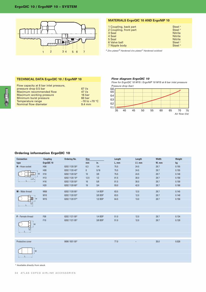
MATERIALS ErgoQIC 10 AND ErgoNIP 10
1 Coupling, back part Steel a
2 Coupling, front part Steel b
3 Seal Nitrile4 Seal Nitrile5 Seal Nitrile6 Valve ball Steel c
7 Nipple body Steel b
TECHNICAL DATA ErgoQIC 10 / ErgoNIP 10
Flow capacity at 6 bar inlet pressure,pressure drop 0.5 bar 67 l/sMaximum recommended flow 47 l/sMaximum working pressure 16 barMinimum burst pressure 60 barTemperature range –10 to +70 °CNominal flow diameter 9.4 mm
a Zinc plated b Hardened zinc plated c Hardened oxidized
4035 45 50 55 60 65 70
0.50.40.30.20.1
75
0.6
Flow diagram ErgoQIC 10
Pressure drop (bar)
Air flow (l/s)
Flow for ErgoQIC 10 M15 / ErgoNIP 10 M15 at 6 bar inlet pressure
LL1
W
LL1
w
LL1
W
L
W
* Available directly from stock.

Ordering information ErgoNIP 10
Connection Nipple Ordering No. Size Length Length Length Width Weight
type ErgoNIP 10 mm in L, mm L1, mm L2, mm W, mm kg
H – Hose socket H06 8202 1220 35* 6.3 1/4 47.0 18.0 24.5 22.2 0.025
H08 8202 1220 43* 8 5/16 47.0 18.0 24.5 22.2 0.026
H10 8202 1220 50* 10 3/8 47.0 18.0 24.5 22.2 0.026
H13 8202 1220 68* 12.5 1/2 52.5 18.0 30.0 22.2 0.035
H16 8202 1220 76* 16 5/8 53.0 18.0 30.0 26.5 0.043
H20 8202 1220 77* 19 3/4 63.0 18.0 40.0 28.7 0.058
S H – Safety Hosea SH06 8202 1220 37* 6.3 1/4 62.5 18.0 38.0 26.5 0.068
SH08 8202 1220 45* 8 5/16 62.5 18.0 38.0 26.5 0.070
SH10 8202 1220 52* 10 3/8 62.5 18.0 38.0 26.5 0.072
SH13 8202 1220 70* 12.5 1/2 68.0 18.0 38.0 26.5 0.080
SH16 8202 1220 74* 16 5/8 68.0 18.0 38.0 26.5 0.082
SH20 8202 1220 75* 19 3/4 78.0 18.0 40.0 26.5 0.097
M – Male thread M08 8202 1220 01* 1/4 BSP 34.5 18.0 12.0 22.2 0.026
M10 8202 1220 19* 3/8 BSP 34.5 18.0 12.0 22.2 0.026
M15 8202 1220 27* 1/2 BSP 36.0 18.0 13.0 26.5 0.040
F – Female thread F08 8202 1220 84* 1/4 BSP 37.0 18.0 12.5 22.2 0.037
F10 8202 1220 86* 3/8 BSP 37.0 18.0 12.5 22.2 0.029
F15 8202 1220 88* 1/2 BSP 41.0 18.0 13.5 28.7 0.066
a) For hoses longer than 3 metres, for instructions see page 31 and 39. * Available directly from stock.
A T L A S C O P C O A I R L I N E A C C E S S O R I E S 3 5
ErgoQIC 10 / ErgoNIP 10 – SYSTEM
L1 L2
L
W
L1L2
L
W
L1 L2
L
W
L1 L2
L
W

Ordering information QIC 08
Connection Coupling Ordering No. Size Length Length Width Weight
type QIC 08 mm in. L, mm L1, mm W, mm kg
H – Hose socket H06 8202 1300 04* 6.3 1/4 64.0 18.5 24.0 0.096
H08 8202 1300 12* 8 5/16 66.0 20.5 24.0 0.096
H10 8202 1300 20* 10 3/8 67.0 23.0 24.0 0.099
M – Male thread M08 8202 1300 38* 1/4 BSP 54.5 10.0 24.0 0.095
M10 8202 1300 46* 3/8 BSP 53.5 10.0 24.0 0.096
F – Female thread F08 8202 1300 53* 1/4 BSP 56.5 15.0 24.0 0.110
F10 8202 1300 61* 3/8 BSP 56.5 13.5 24.0 0.100
3 6 A T L A S C O P C O A I R L I N E A C C E S S O R I E S
QIC 08 / NIP 08 – SYSTEM
1 2 3 4 5 7 86
MATERIALS QIC 08 AND NIP 08
1 Coupling body Steel2 Valve Brass3 Seal Nitrile4 Springs Stainless steel5 Seal Nitrile6 Locking sleeve Steela
7 Balls Stainless steel8 Nipple body Steela
TECHNICAL DATA QIC 08 / NIP 08
Flow capacity at 6 bar inlet pressure,pressure drop 0.5 bar 16 l/sMaximum recommended flow 11 l/sMaximum working pressure 16 barMinimum burst pressure 64 barTemperature range –20 to +80 °CNominal flow diameter 5.0 mm
a Hardened zinc plated
109 11 12 13 14 15 16
0.50.40.30.20.1
17
0.6
Flow diagram QIC 08
Pressure drop (bar)
Air flow (l/s)
Flow for QIC 08 M08 / NIP 08 F08 at 6 bar inlet pressure
QIC 08 connect with nipples according to American MilitaryStandard MIL-C 4109C, interchangeable with ARO, HANSEN, etc.
L1L
W
L1L
W
L1L
W
* Available directly from stock.

Ordering information NIP 08
Connection Nipple Ordering No. Size Length Length Length Width Weight
type NIP 08 mm in L, mm L1, mm L2, mm W, mm kg
H – Hose socket H06 8202 1205 18* 6.3 1/4 51.0 24.0 24.0 15.0 0.019
H08 8202 1205 26* 8 5/16 51.0 24.0 24.0 15.0 0.021
H10 8202 1205 34* 10 3/8 51.0 24.0 24.0 15.0 0.023
M – Male thread M06 8202 1205 42* 1/8 BSP 39.0 24.0 9.5 20.0 0.025
M08 8202 1205 59 * 1/4 BSP 39.0 24.0 9.5 20.0 0.029
M10 8202 1205 67* 3/8 BSP 40.0 24.0 10.0 22.0 0.029
F – Female thread F08 8202 1205 83* 1/4 BSP 37.0 24.0 9.5 20.0 0.028
F10 8202 1205 91* 3/8 BSP 42.0 24.0 13.5 23.0 0.034
A T L A S C O P C O A I R L I N E A C C E S S O R I E S 3 7
QIC 08 / NIP 08 – SYSTEM
QICQIC couplings are the traditional, sure answer when hoses have tobe changed from one air tool to another, or when making fast con-nections to an air outlet. The small size of QIC couplings makesthem easy and convenient to work with in combination with airtools.
FOUR EASY STEPS TO CONNECT AND DISCONNECT
Connection
1. Slot in
Disconnection
3. Pull locking sleeve back
4. Disconnect gently
L1 L2
L
W
L1 L2
L
W
L1 L2
L
W
2. Press togehter
* Available directly from stock.

Ordering information QIC 10
Connection Coupling Ordering No. Size Length Length Width Weight
type QIC 10 mm in. L, mm L1, mm W, mm kg
H – Hose socket H06 8202 1302 02* 6.3 1/4 66.0 16.0 24.0 0.097
H08 8202 1302 10* 8 5/16 68.5 21.5 24.0 0.097
H10 8202 1302 28* 10 3/8 69.0 20.5 24.0 0.099
H13 8202 1302 34* 12.5 1/2 67.0 21.0 24.0 0.097
M – Male thread M08 8202 1302 36* 1/4 BSP 56.5 10.0 24.0 0.096
M10 8202 1302 44* 3/8 BSP 55.5 10.0 24.0 0.097
MT – Male Taper thread MT15 8202 1302 51* 1/2 BSPT 54.5 15.0 25.5 0.100
F – Female thread F08 8202 1302 69* 1/4 BSP 59.0 15.0 24.0 0.110
3 8 A T L A S C O P C O A I R L I N E A C C E S S O R I E S
QIC 10 / NIP 10 – SYSTEM
1 2 3 4 5 6 7 8
MATERIALS QIC 10 AND NIP 10
1 Coupling body Steel2 Valve Brass3 Seal Nitrile4 Springs Stainless steel5 Seal Nitrile6 Balls Stainless steeel7 Locking sleeve Steela
8 Nipple body Steela
TECHNICAL DATA QIC 10 / NIP 10
Flow capacity at 6 bar inlet pressure,pressure drop 0.5 bar 29 l/sMaximum recommended flow 20 l/sMaximum working pressure 16 barMinimum burst pressure 64 barTemperature range –20 to +80 °CNominal flow diameter 7.1 mm
a Hardened zinc plated
0.40.30.20.1
0.60.5
1614 18 20 22 24 26 28 30 32
Flow diagram QIC 10
Pressure drop (bar)
Air flow (l/s)
Flow for QIC 10 M10/ NIP 10 M10 at 6 bar inlet pressure
L1L
W
L1L
W
L1L
W
L1L
W
* Available directly from stock.

Ordering information NIP 10
Connection Nipple Ordering No. Size Length Length Length Width Weight
type NIP 10 mm in L, mm L1, mm L2, mm W, mm kg
H – Hose socket H05 8202 1202 03* 5 3/16 46.0 25.0 19.0 18.0 0.019
H06 8202 1202 11* 6.3 1/4 51.0 25.0 24.0 18.0 0.022
H08 8202 1202 94* 8 5/16 51.0 25.0 24.0 18.0 0.026
H10 8202 1202 29* 10 3/8 51.0 25.0 24.0 18.0 0.028
H13 8202 1202 34* 12.5 1/2 57.0 25.0 30.0 21.0 0.036
SH – Safety Hose a SH06 8202 1203 10* 6.3 1/4 69.5 25.0 45.0 27.0 0.074
SH08 8202 1203 36* 8 5/16 69.5 25.0 45.0 27.0 0.075
SH10 8202 1203 28* 10 3/8 69.5 25.0 45.0 27.0 0.080
M – Male thread M06 8202 1202 37* 1/8 BSP 38.0 25.0 9.5 19.0 0.023
M08 8202 1202 45* 1/4 BSP 38.5 25.0 10.0 19.0 0.025
M10 8202 1202 52* 3/8 BSP 40.0 25.0 10.0 21.4 0.032
MT – Male Taper thread MT08 8202 1202 60* 1/4 BSPT 42.0 25.0 13.0 19.0 0.028
MT10 8202 1202 78* 3/8 BSPT 43.5 25.0 14.5 21.0 0.025
MT15 8202 1203 02* 1/2 BSPT 50.0 25.0 18.5 26.0 0.057
F – Female thread F08 8202 1202 86* 1/4 BSP 38.0 25.0 10.0 19.0 0.028
a) For hoses longer than 3 metres, for instructions see above and page 31. * Available directly from stock.
A T L A S C O P C O A I R L I N E A C C E S S O R I E S 3 9
QIC 10 / NIP 10 – SYSTEM
SAFETY HOSE NIPPLES – SHSafety hose nipples are recommended for use with hoses longerthan 3 metres.
BenefitsBetter working environment minimum noise bang when discon-necting. Safer work stations no whipping hoses as recoil is effec-tively dampened.
How does it workThe safety nipple is equipped with a ventilating check valve. Thecheck valve is opened when air flows forward, see in figure. Whenthe nipple is disconnected from the coupling, the air in the hosewill try to expand very quickly on the nipple side. This causes thebang and recoil effect from hoses. If the safety hose nipple is used,the check valve will close at point of disconnection, see B in figu-re. The air will be released in a controlled way through a small holein the check valve and sound bangs and recoils are avoided.
L1 L2L
W
L1L
W
L2
L1 L2L
W
L1 L2L
W
L1 L2L
W
A B

4 0 A T L A S C O P C O A I R L I N E A C C E S S O R I E S
QIC 15 / NIP 15 – SYSTEM
Ordering information QIC 15
Connection Coupling Ordering No. Size Length Length Width Weight
type QIC 15 mm in. L, mm L1, mm W, mm kg
H – Hose socket H10 8202 1304 00* 10 3/8 80.0 20.5 28.0 0.165
H13 8202 1304 18* 12.5 1/2 79.0 21.0 28.0 0.165
H16 8202 1304 26* 16 5/8 80.0 23.0 28.0 0.167
M – Male thread M08 8202 1304 34* 1/4 BSP 69.0 10.0 28.0 0.165
M10 8202 1304 42* 3/8 BSP 66.5 10.0 28.0 0.160
M15 8202 1304 59* 1/2 BSP 66.5 10.5 28.0 0.162
F – Female thread F15 8202 1304 67* 1/2 BSP 71.0 18.0 28.0 0.178
1 2 3 4 5 6 7 8
MATERIALS QIC 15 AND NIP 15
1 Coupling body Steel2 Valve Brass3 Seal Nitrile4 Springs Stainless steel5 Seal Nitrile6 Locking sleeve Steela
7 Balls Stainless steel8 Nipple body Steela
TECHNICAL DATA QIC 15 / NIP 15
Flow capacity at 6 bar inlet pressure,pressure drop 0.5 bar 57 l/sMaximum recommended flow 37 l/sMaximum working pressure 10 barMinimum burst pressure 40 barTemperature range –20 to +80 °CNominal flow diameter 10.0 mm
a Hardened zinc plated
3530 40 45 50 55
0.50.40.30.20.1
60
0.6
Flow diagram QIC 15
Pressure drop (bar)
Air flow (l/s)
Flow for QIC 15 F15 / NIP 15 F15 at 6 bar inlet pressure
L1L
W
L1L
W
L1L
W
* Available directly from stock.

A T L A S C O P C O A I R L I N E A C C E S S O R I E S 4 1
QIC 15 / NIP 15 – SYSTEM
Ordering information NIP 15
Connection Nipple Ordering No. Size Length Length Length Width Weight
type NIP 15 mm in L, mm L1, mm L2, mm W, mm kg
H – Hose socket H06 8202 1251 03* 6.3 1/4 55.0 28.0 24.0 20.0 0.028
H08 8202 1252 28* 8 5/16 55.0 28.0 24.0 20.0 0.032
H10 8202 1251 11* 10 3/8 55.0 28.0 24.0 20.0 0.032
H13 8202 1251 29* 12.5 1/2 59.0 28.0 28.0 22.0 0.036
H16 8202 1251 37* 16 5/8 59.0 28.0 28.0 22.0 0.045
SH – Safety Hose a SH10 8202 1203 44* 10 3/8 72.5 28.0 48.5 27.0 0.082
SH13 8202 1203 51* 12.5 1/2 78.0 28.0 49.0 27.0 0.087
SH16 8202 1203 69* 16 5/8 78.0 28.0 49.0 27.0 0.094
M – Male thread M10 8202 1251 45* 3/8 BSP 43.5 28.0 11.0 20.5 0.034
M15 8202 1251 52* 1/2 BSP 45.5 28.0 12.5 26.0 0.046
MT – Male Taper thread MT08 8202 1251 60* 1/4 BSPT 47.5 28.0 14 20.5 0.034
MT10 8202 1251 78* 3/8 BSPT 47.5 28.0 14 20.5 0.039
MT15 8202 1251 86* 1/2 BSPT 52.5 28.0 19 25.5 0.055
F – Female thread F08 8202 1251 94* 1/4 BSP 43.0 28.0 12.0 19.5 0.036
F10 8202 1252 02* 3/8 BSP 46.0 28.0 14.0 22.5 0.040
F15 8202 1252 10* 1/2 BSP 51.0 28.0 17.0 27.0 0.057
a) For hoses longer than 3 metres, for instructions see page 31 and 39. * Available directly from stock.
L1 L2L
W
L1
L2
L
W
L1 L2L
W
L1 L2L
W
L1 L2L
W

4 2 A T L A S C O P C O A I R L I N E A C C E S S O R I E S
CLAW – SYSTEM
1 2 3
MATERIALS CLAW COUPLINGS
1 Seal Nitrile2 Seal seat Lathe-turned grooves3 Coupling body Steela
TECHNICAL DATA CLAW
Flow capacity at 6 bar inlet pressure,pressure drop 0.5 bar >>290 l/sMaximum recommended flow 290 l/sMaximum working pressure 10 barMinimum burst pressure 50 barTemperature range –20 to +80 °CNominal flow diameter B in Ordering info.
a Drop forged, hardened zinc plated
500 100 150 200 250
0.200.150.100.05 0
300
0.25
Claw couplings flow diagram
Pressure drop (bar)
Air flow (l/s)
Flow for 2 pieces of CLAW M25 at 6 bar inlet pressure
Ordering information CLAW
Connection Coupling Ordering No. Size Bore Length Length Width Weight
type CLAW mm in B, mm L, mm L1, mm W, mm kg
H – Hose H06 9000 0308 00* 6.3 1/4 5.0 43 27 62 0.110
H10 9000 0309 00* 10 3/8 8.0 46 30 62 0.130
H13 9000 0310 00* 12.5 1/2 10.5 48 32 62 0.140
H16 9000 0311 00* 16 5/8 13.5 51 35 62 0.140
H20 9000 0312 00* 19 3/4 17.0 58 42 62 0.150
H25 9000 0313 00* 25 1 22.0 63 47 62 0.170
LNH – Lock nut, hose LNH10 9000 0260 00* 10 3/8 8.0 70 30 62 0.650
LNH13 9000 0261 00* 12.5 1/2 10.5 73 33 62 0.650
LNH16 9000 0262 00* 16 5/8 13.5 76 36 62 0.650
LNH20 9000 0263 00* 19 3/4 17.2 82 42 62 0.710
LNH25 9000 0264 00* 25 1 22.0 83 43 62 0.710
M – Male thread M10 9000 0300 00* 3/8 BSP 11.2 23 9 62 0.240
M15 9000 0301 00* 1/2 BSP 14.8 25 10 62 0.260
M20 9000 0302 00* 3/4 BSP 19.0 26 11 62 0.270
M25 9000 0303 00* 1 BSP 25.0 29 11 62 0.280
F – female thread F10 9000 0304 00* 3/8 BSP 15.0 25 11 62 0.260
F15 9000 0305 00* 1/2 BSP 18.6 25 14 62 0.300
F20 9000 0306 00* 3/4 BSP 24.0 27 15 62 0.310
F25 9000 0307 00* 1 BSP 25.0 35 19 62 0.330
Extra seal for CLAW couplings 9000 0000 00a* for type H, M and F
9000 0015 00* for LNH10, 13, 16
9000 0268 00b* for LNH20 and 25
Safety lock spring 3176 8640 90* Protection Cover 9000 0314 00*
25 pieces for CLAW couplings
a) for temperature up to +200 °C = 9000 000 01b) for temperature up to +200 °C = 9000 0319 00
ORDERING GUIDEThe coupling head is the same for all sizes, and can therefore becombined freely. One seal is delivered with each coupling.
IMPROVED WORKING SAFETYThe LNH-type (CLAW coupling with lock nut) will always givesafe locking. Use one LNH-coupling with either H, M or F-type ofcoupling.OrUse safety lock spring for safe locking of H, M and F type. Foreach pair of couplings one safety lock spring is required.
L1
L
W
L1
L
W
L1
L
W
L1
L
W
* Available directly from stock.

A T L A S C O P C O A I R L I N E A C C E S S O R I E S 4 3
CONNECTIONS
Thread Hose size Ordering No.
In mm in.
1/8 BSP 3.2 1/8 9000 0523 00*
1/8 BSPT 5 3/16 4010 0031 00*
1/8 BSPT 6.3 1/4 9000 0240 00*
1/4 BSP 3.2 1/8 9000 0524 00*
1/4 BSPT 6.3 1/4 9000 0241 00*
1/4 BSPT 8 5/16 9090 1715 00*
1/4 BSPT 10 3/8 9000 0247 00*
3/8 BSPT 10 3/8 9000 0242 00*
3/8 BSPT 12.5 1/2 9000 0248 00*
1/2 BSPT 12.5 1/2 9000 0243 00*
1/2 BSPT 16 5/8 9000 0244 00*
1/2 BSPT 20 3/4 4150 0429 00*
3/4 BSPT 20 3/4 9000 0245 00*
1 BSPT 25 1 9000 0246 00*
HOSE CONNECTION
Hose connection in steel. Male thread hose nipple.
.Male Female
thread thread
in in Ordering No.
1/4 BSP 1/8 BSP 9090 0799 00*
3/8 BSP 1/4 BSP 9090 0798 00*
1/2 BSP 1/4 BSP 9090 1469 00*
1/2 BSP 3/8 BSP 9090 0797 00*
3/4 BSP 1/2 BSP 9090 0796 00*
1 BSP 3/4 BSP 9090 0795 00*
BUSHING
Male thread female thread.
.Female thread Male thread
in in Ordering No.
1/4 BSP 1/8 BSP 9721 4000 94*
3/8 BSP 1/4 BSP 9721 4000 92*
1/2 BSP 3/8 BSP 9721 4000 93*
REDUCING NIPPLE
In brass.
.Air outlet Max Swivel
Air Male bend from
inlet BSP centre line Ordering No.
1/4” BSPa 1/4” 45° 4210 3135 00*
5/16" hose 1/4” 30° 4210 3134 80*a Female thread.
SWIVELS
Recommended flow max 10 l/s.
.Hose diameter
Outside/Inside Male thread
mm in Ordering No.
10/8a 1/4 BSP 9721 4002 89*
10/8a 3/8 BSP 9721 4002 90*
12/9 1/4 BSP 9721 4000 86
12/10b 3/8 BSP 9721 4000 88
15/12.5c 1/2 BSP 9721 4000 89*Male threaded hose nipple with clamp nut should be used with female threaded quickcouplings.
Spring guard in steel. See fig. 2.
Hose diameter
Outside/Inside
mm Ordering No.
10/8a 9721 4002 88*
12/10b 9721 4000 91
15/12c 9721 4002 85*The spring guard should be used with the clamp nut above.a CABLAIR 08. b CABLAIR 10. c CABLAIR 13.
HOSE CONNECTIONWITH CLAMP NUT ANDSPRING GUARD
Clamp nut, brass.See fig. 1.
DOUBLE CONNECTIONMale taper thread male taper thread.
From To
thread thread
in in Ordering No.
1/8 BSPT 1/8 BSPT 9090 0100 00*
1/8 BSPT 1/4 BSPT 9090 0110 00*
1/4 BSPT 1/4 BSPT 9090 0120 00*
1/4 BSPT 3/8 BSPT 9090 0130 00*
3/8 BSPT 3/8 BSPT 9090 0140 00*
3/8 BSPT 1/2 BSPT 9090 0150 00*
1/2 BSPT 1/2 BSPT 9090 0160 00*
1/2 BSPT 3/4 BSPT 9090 0170 00*
3/4 BSPT 3/4 BSPT 9090 0180 00*
3/4 BSPT 1 BSPT 9090 0190 00*
1 BSPT 1 BSPT 9090 0200 00*
DOUBLE ADJUSTABLE CONNECTIONMale thread male thread.
From To
thread thread
in in Ordering No.
1/2 BSP 1/2 BSP 9090 0806 00*
1 BSP 1 BSP 9090 0810 00** Available directly from stock.
HOSE JOINTING NIPPLE IN STEELFor jointing of PVC and rubber hose.
Hose size Bore
Mm in. mm Ordering No.
6.3 1/4 5 9000 0214 00*
10 3/8 9 9000 0215 00*
12.5 1/2 12 9000 0216 00*
16 5/8 14 9000 0217 00*
20 3/4 17 9000 0218 00*
25 1 23 9000 0219 01*
FIG. 1
FIG. 1FIG. 2

4 4 A T L A S C O P C O A I R L I N E A C C E S S O R I E S
CLAMPS AND SEALS
SIMPLE PRESSURECLAMPS FOR PVC HOSES
One-lugged zinc-plated steel clampwith thin walled stainless steel insert.
For For One-lugged
CABLAIR PVC Steel clamp Ordering No.
– – 5.2-6.2 0347 0122 18*
– – 5.9-7.0 0347 0122 19*
– 03 7.0-8.5 0347 0122 05*
06 05 8.5-10.0 0347 0122 06*
08 06 9.8-11.8 0347 0122 07*
– 08 11.3-13.3 0347 0122 08*
10 – 12.8-14.8 0347 0122 09*
– 10 14.6-16.8 0347 0122 10*
13 – 16.5-18.8 0347 0122 11*
– 13 18.0-20.3 0347 0122 12*
16 – 20.2-22.8 0347 0122 13*
– – 22.0-24.8 0347 0122 14*
20 – 23.3-26.3 0347 0122 15*
– – 26.5-30.0 0347 0122 16*
25 – 29.8-33.1 0347 0122 22*
MEDIUM PRESSURE CLAMPSFOR RUBBER HOSESWorm-drive bright zinc-plated clamp.
For For Medium clamp
TURBO RUBAIR worm drive Ordering No.
– 06 11.0-17.0 0347 6102 00*
13 10 13.0-20.0 0347 6104 00*
16 13 15.0-24.0 0347 6105 00*
– 16 19.0-28.0 0347 6106 00*
20 20 22.0-32.0 0347 6107 00*
— 20 26.0-38.0 0347 6109 00*
FIBRE GASKET
For coupling Fibre gasket
with parallel thread Ordering No.
M5 0657 5710 00*
1/8” BSP 0657 5742 00*
1/4” BSP 0657 5764 00*
3/8” BSP 0657 5785 00*
1/2” BSP 0653 0500 01*
3/4” BSP 0657 5823 00*
1” BSP 0657 5830 00** Available directly from stock.
MEDIUM PRESSURECLAMPS FOR PVC ANDPU HOSES
Worm-drive bright zinc-plated clamp.
For For Medium clamp
CABLAIR PVC, POLUR worm drive Ordering No.
– – 8.0-14.0 0347 6102 00*
– 08 11.0-17.0 0347 6103 00*
– 10 11.0-17.0 0347 6103 00*
– – 13.0-20.0 0347 6104 00*
16 13 15.0-24.0 0347 6105 00*
20 16 19.0-28.0 0347 6106 00*
– 20 22.0-32.0 0347 6107 00*
25 25 26.0-38.0 0347 6109 00*
– – 32.0-44.0 0347 6111 00*
– – 38.0-50.0 0347 6112 00
– – 50.0-65.0 0347 6113 00*
HEAVY-DUTY PRESSURECLAMPS FOR RUBBER-HOSESTwo-piece malleable cast iron.
For For Heave-duty
TURBO RUBAIR clamp Ordering No.
– 16 22.0-25.0 9000 0194 00*
20 20 25.0-28.0 9000 0195 00*
– – 29.0-32.0 9000 0196 00*
– 25 34.0-38.0 9000 0197 00*
RUBBER SEALING RINGS
For Rubber spare
coupling sealing ring
with for double adjustable
thread connectionsa
in Ordering No.
1/2 BSP 9090 0884 00*
1 BSP 9090 0886 00*a See page 43.

First hose Second hose
BLOCK
RUBBEBLOW PROTECTOR
BLOW PROTECTORBLOCKWhen a fitting comes loosefrom a pressurized hose, thehose starts blowing compressedair in an uncontrolled way. Theblow protector shuts off the air-flow and thus minimizes therisk of personal injuries and anydamage of the work piece andsurrounding.
The selection parameters are the air pressure and the air flow. Forproper function the air pressure shall be set on 7 bar in order toreach 6 bar at the air tool. The air flow is determined by the airconsumption of the tool and the hose length.
Air flow First hose Second hose Shut off Female
air tool length size length size air flow thread BSP
l/s m mm m mm l/s Product in Ordering No.
0- 5 1 – 5 6.3 0 – 7.8 BLOCK 08L 1/4 8202 0100 50*
0- 5 6 – 10 8 0 – 13 BLOCK 08H 1/4 8202 0100 52*
0- 8 1 – 5 8 0 – 13 BLOCK 08H 1/4 8202 0100 52*
0- 8 6 – 10 10 0 – 13 BLOCK 08H 1/4 8202 0100 52*
0-10 1 – 10 10 0 – 13 BLOCK 08H 1/4 8202 0100 52*
0-10 11 – 20 12.5 0 – 13 BLOCK 08H 1/4 8202 0100 52*
0-14 1 – 5 10 0 – 18 BLOCK 10L 3/8 8202 0100 54*
0-14 6 – 10 13 0 – 18 BLOCK 10L 3/8 8202 0100 54*
0-15 11 – 20 16 0 – 32 BLOCK 10H 3/8 8202 0100 56*
0-25 1 – 5 12.5 0 – 32 BLOCK 10H 3/8 8202 0100 56*
0-25 6 – 10 16 0 – 32 BLOCK 10H 3/8 5202 0100 56*
0-35 1 – 5 12.5 0 – 45 BLOCK 15H 1/2 8202 0100 58*
0-35 6 – 10 16 0 – 45 BLOCK 15H 1/2 8202 0100 58*
0-35 11 – 20 19 0 – 45 BLOCK 15H 1/2 8202 0100 58*
0-60 1 – 10 19 0 – 75 BLOCK 20H 3/4 8202 0100 60*
0-60 1 – 10 19 20 25 75 BLOCK 20H 3/4 8202 0100 60*
0-70 1 – 7 19 0 25 86 BLOCK 25H 1 8202 0100 62*
0-70 8 – 20 25 0 25 86 BLOCK 25H 1 8202 0100 62*
0-70 1 – 20 25 20 25 86 BLOCK 25H 1 8202 0100 62*
Spiral hose
BLOCK
16 mm hose
Selecting table usingstandard hoses
The air flow, hose length andhose sizes must all be withinthe recommended range inorder to choose the right modelof blow protector. The secondhose is only used when hoseslonger than 20 m are used. Thesecond hose will always be 20m and the first hose will be cutto the right length. Use cou-plings in your installation withhigh air flow capacity such asQIC 10, QIC 15, ErgoQIC 08,ErgoQIC 10 and CLAW orsimilar couplings to ensure pro-per use of the blow protector.
When working with impactwrenches and pulse tools caremust be taken in the choice ofblow protector. The value ofair flow under full load mustbe increased by 50% whenselecting blow protector ofimpact wrenches and pulsetools as there otherwise will bea risk for shut-off at idling.
BLOCK has automatic reset.When the air is switched onagain the valve in BLOCK opens and is automatically reset.
Selection from the tables; There are two tables below, the first isfor choosing a blow protector for standard hoses, the other forchoosing a blow protector for spiral hoses and hose balancers.
Spiral hose or balancer
Air flow Hose Hose Shut off Female
air tool length size air flow thread BSP
in Model m mm l/s Product in Ordering No.
0- 4 SPI 06-3 2.5 6 8.3 BLOCK 08L 1/4 8202 0100 50*
0- 6 HRIL 3 1.4 – 8.3 BLOCK 08L 1/4 8202 0100 50*
0- 6 SPI 1S 2.0 6 8.3 BLOCK 08L 1/4 8202 0100 50*
0- 6 SPI 2L 6.0 8 8.3 BLOCK 08L 1/4 8202 0100 50*
0- 8 HRIL 4 1.1 – 14 BLOCK 08H 1/4 8202 0100 52*
0- 8 SPI 09-3 2.5 9 14 BLOCK 08H 1/4 8202 0100 52*
0- 8 SPI 2M 4.0 8 14 BLOCK 08H 1/4 8202 0100 52*
0- 11 SPI 2S 3.0 8 14 BLOCK 08H 1/4 8202 0100 52*
0- 11 SPI 2L 6.0 11 14 BLOCK 08H 1/4 8202 0100 52*
0- 15 SPI 3M 4.0 11 19 BLOCK 10L 3/8 8202 0100 54*
0- 20 SPI 3S 3.0 11 32 BLOCK 10H 3/8 8202 0100 56** Available directly from stock.
A T L A S C O P C O A I R L I N E A C C E S S O R I E S 4 5

4 6 A T L A S C O P C O A I R L I N E A C C E S S O R I E S
HOSES
PVC HOSESCABLAIR HOSESSuperlight flexible PVC-hose
CABLAIR is made of high-strength, high-performance PVC-materialin combination with optimum braid angle polyester-reinforced fibres.CABLAIR can withstand the same pressures and temperatures asstandard hoses. CABLAIR is recommended for indoor use. Low weight Extremely low weight, 30-50% less than conventio-
nal hoses in combination with low-weight tools this makes anideal ergonomic solution.
Soft and flexible Extremely flexible softer than ordinary PVC-hoses.
Easy to handle supplied in 30 metre coils wrapped in shrink film. Working temperature 25°C to +60°C. Inside diameter according to ISO 4397. Patents pending. Blue colour The international identification colour for compres-
sed air.
TECHNICAL DATA / ORDERING INFORMATION CABLAIR HOSEMax. Max.
Size working burst pressure Max. rec. Weight per Temperature
Inside dia. Outside dia. pressure at 20ºC air flowa 30 m coil range ºC
Model mm in mm bar bar l/s kg min. max. Ordering No.
CABLAIR 06 6.3 1/4 9 18 54 4 1.2 -25 +60 9093 0035 11*
CABLAIR 08 8 5/16 10.5 18 54 7.5 1.7 -25 +60 9093 0035 11*
CABLAIR 10 10 3/8 13 14 42 13 2.1 -25 +60 9093 0035 71*
CABLAIR 13 12.5 1/2 16.5 13 39 21 3.0 -25 +60 9093 0036 01*
CABLAIR 16 16 5/8 21.5 11 33 43 5.4 -25 +60 9093 0036 31*
CABLAIR 20 19 3/4 24 11 33 75 5.8 -25 +60 9093 0036 61*
CABLAIR 25 25 1 31 10 30 125 10.4 -25 +60 9093 0036 91*a The pressure drop will be 0.2 bar on a hose length of 5 m, including 2 nipples and at an inlet pressure of 7 bar. For more specific data, see pressure drop diagram for hoses onpage 48.
TECHNICAL DATA / ORDERING INFORMATION PVC HOSEMax. Max.
Size working burst pressure Max. rec. Weight per Temperature
Inside dia. Outside dia. pressure at 20ºC air flowa 30 m coil range ºC
Model mm in mm bar bar 1/s kg min. max. Ordering No.
PVC 03 3.2 1/8 7 20 60 0.7 1.4 -25 +60 9093 0037 21*
PVC 05 5 3/16 9 18 54 2.1 1.9 -25 +60 9093 0037 51*
PVC 05 – 100c 5 3/16 9 18 54 2.1 – -25 +60 8202 0501 05*
PVC 06 6.3 1/4 11 18 54 4 2.5 -25 +60 9093 0037 81*
PVC06 – ESDb 6.3 1/4 11 18 54 4 2.5 -25 +60 8202 0501 06*
PVC 08 8 5/16 12 18 54 7.5 2.9 -25 +60 9093 0038 11*
PVC 10 10 3/8 14 14 42 13 3.7 -25 +60 9093 0038 41*
PVC 13 12.5 1/2 18 13 39 21 5.9 -25 +60 9093 0038 71*
PVC 16 16 5/8 22 12 36 43 7.2 -25 +60 9093 0039 01*
PVC 20 19 3/4 25 12 36 75 8.3 -25 +60 9093 0039 31*
PVC 25 25 1 32 11 33 125 12.5 -25 +60 9093 0039 61*a The pressure drop will be 0.2 bar on a hose length of 5 m, including 2 nipples and at an inlet pressure of 7 bar. For more specific data, see pressure drop diagram for hoses onpage 48 b PVC 06-ESD. Anti-static hose c PVC05-100. 100 m coil. Weight 6.35 kg.* Available directly from stock.
PVC HOSESStrong for heavy-duty applications
The PVC hose has high resistance to abrasion, which makes it theideal hose for tough working conditions such as workshops, factori-es, garages, etc. It is mainly recommended for indoor use.The PVC hose is available in 9 diameters ranging from 3 mm to 25mm (1/8" to 1" inside diameter) to suit a wide variety of fittings. Transparent facilitates inspection. Pliable easily follows working movements. Long service life. Inside diameter according to ISO 4397. Working temperature between 25°C and +60°C. Easy to handle supplied in 30 metre coils. Blue colour The international identification colour for compres-
sed air.
Complete hose sets, see installation proposals page 66 72.
The PVC hose can also be used in many other fields to carry fluids.Complete hose sets, see installation proposals page 66 72.

A T L A S C O P C O A I R L I N E A C C E S S O R I E S 4 7
HOSES
RUBBER HOSES
TURBO – RUBBER HOSES
Super-light flexible rubber hose. TURBO is recommended forindoor and outdoor use. The ideal hose for a wide variety of appli-cations, such as foundries, shipyards, engineering workshops aswell as on construction sites. The hose is antistatic, 1.6x10¹⁰ Ω/m.Low weight, 40-50% less than conventional rubber hoses. Soft andflexible extremely flexible, softer than ordinary rubber hoses.Supplied in 20 metre coils wrapped in shrink film. Complete hosesets, see installation proposals page 66 72.
TECHNICAL DATA / ORDERING INFORMATION TURBO RUBBER HOSEMax. Max.
Size working burst pressure Max. rec. Weight per Temperature
Inside dia. Outside dia. pressure at 20ºC air flowa 20 m coil range ºC
Model mm in mm bar bar l/s kg min. max. Ordering No.
TURBO 13 12.5 1/2 18.6 16 60 21 3.9 –25 +90 9093 0057 91*
TURBO 16 16.5 5/8 22.5 16 60 43 4.8 –25 +90 9093 0057 31*
TURBO 20 20.1 3/4 26.1 16 60 75 5.4 –25 +90 9093 0057 61*a The pressure drop will be 0.2 bar on a hose length of 5 m, including 2 nipples and at an inlet pressure of 7 bar.* For more specific data, see pressure drop diagram for hoses on page 48.
RUBAIR – RUBBER HOSES
A double-reinforced, strong hose extra strong and tough.RUBAIR is recommended for indoor and outdoor use. The idealhose for a wide variety of applications, including foundries, shipy-ards, engineering workshops, and construction sites. The hose isantistatic, 1x10⁹ Ω/m. Supplied in 20 metre coil wrapped in shinkfilm. Complete hose sets, see installation proposals page 66 72.
TECHNICAL DATA / ORDERING INFORMATION RUBAIR RUBBER HOSEMax. Max.
Size working burst pressure Max. rec. Weight per Temperature
Inside dia. Outside dia. pressure at 20ºC air flowa 20 m coil range ºC
Model mm in mm bar bar l/s kg min. max. Ordering No.
RUBAIR 06 6.3 1/4 11.3 16 64 4 2.0 –40 +90 8202 0401 06*
RUBAIR 10 10 3/8 16.0 16 64 13 3.6 –40 +90 8202 0402 10*
RUBAIR 13 12.5 1/2 19.1 16 64 21 4.7 –40 +90 8202 0403 13*
RUBAIR 16 16 5/8 23.0 16 64 43 6.1 –40 +90 8202 0404 16*
RUBAIR 20 19 3/4 26.6 16 64 75 7.8 –40 +90 8202 0405 20*
RUBAIR 25 25 1 34.0 16 64 125 11.8 –40 +90 8202 0406 25*a The pressure drop will be 0.2 bar on a hose length of 5 m, including 2 nipples and at an inlet pressure of 7 bar. For more specific data, see pressure drop diagram for hoses onpage 48.* Available directly from stock.

4 8 A T L A S C O P C O A I R L I N E A C C E S S O R I E S
HOSES
185
150
125
100
50
20
15
10
5
2
1.5
12 4 6 8 10
25
20
16
13
10
08
06
05
12
PRESSURE DROP DIAGRAM FOR STRAIGHTHOSES
The diagram helps you to choose the right hose according to the airconsumption of the tool and the length of the hose. The purpose ofthe diagram is to ensure that the pressure drop in the hoses does notexceed 0.2 bar.
How to read the diagram:Look up the tools required air consumption at 6 bar. Use this valuein the diagram.
What length of hose do you need? Use this value in the diagram.Look at the diagram to see which hose size you need.Decide which type of hose you need. Atlas Copco Tools has fivedifferent hoses covering all types of needs for pneumatic handtools.
ExampleThe tool has an air consumption of 10 l/s and the application requi-res a hose length of 7 m. These two values have a cross pointslightly under the type 10 size hose (7 m of type10 mm hose givesa value of approximately 12 l/s).
Therefore a 10 hose will be suitable.To simplity the choice of hoses see complete sets in INSTALLA-TION PROPOSALS at page 66 72.
PRESSURE DROP DIAGRAM FOR HOSES TYPECABLAIR, PVC, TURBO, RUBAIR and POLUR
Air flow (l/s)
Inlet pressure 7 barPressure drop 0.2 barTwo hose nipples includet
Ho
se le
ng
th (
m)
POLYURETHANE HOSES
POLUR – POLYURETHANE
POLUR has high resistance to abrasion. The hose is oil-resistant.POLUR has a much longer lifetime compared with PVC hoses. Thepolyurethane hose is an ideal hose in tough working conditionssuch as workshops, factories, garages, shipyards and constructionsites. The POLUR is recommended for indoor and outdoor applica-tions. The POLUR is also very flexible and it keeps its flexibilityeven when working at minus degrees. The hose will when stressed,always retract to its normal shape and keeps its performance duringits entire life.
Working temperature between 30°C to +80°C Easy to handle supplied in 25 m colis Hardness 68/90 Shore A Tested according to ISO 1402
POLUR polyurethane hoses
Recommended
Hose diameter Working Burst air flow for Weight per
inside outside pressure pressure 5 m hose 25 m coil
Model mm in mm bar bar l/s kg Ordering No.
POLUR 08 8 5/16 12 20 60 7.5 2.2 8202 0601 08*
POLUR 10 10 3/8 14 16 50 13 2.5 8202 0602 10*
POLUR 13 13 1/2 18 13 40 21 4.0 8202 0603 13*a The pressure drop will be 0.2 bar on a hose length of 5 m, including 2 nipples and atan inlet pressure of 7 bar. * Available directly from stock.

Technical data / ordering information PEBAX spirals
Size Size Max Max
Inside outside Max. rec. Spiral Working Male WL.
dia. dia. air flowa dia. length threads in BSP Weight unextracted
Model mm mm l/s Ordering No. D, mm WL, m A B kg mm
SPI 06-3 6 8 4 8202 0508 06* 75 3 1/8 1/4 0.197 950
SPI 09-3 9 12 11 8202 0508 14* 120 3 1/4 1/4 0.550 1000a At inlet pressure 6 bar and pressure drop 0.4 bar.
* Available directly from stock.
A T L A S C O P C O A I R L I N E A C C E S S O R I E S 4 9
SPIRAL HOSES
SPIRAL HOSES – SPI
Elastic hose for vertical and horizontal applications. Atlas Copcospiral hoses are available in three different materials: PEBAX,Nylon and Polyurethane. The guide below gives an indication ofthe performance of the different materials.
1
2
100 15 20 25 30 35 40 45 50
0.8
0.4
0
SPI12-6 SPI12-3
5
SPI19-6
Flow diagram SPI 12-3 / SPI 12-6 / SPI 19-6Flow for spiral hoses at 6 bar inlet pressurePressure drop (bar)
Air flow (l/s)
20 4 6 8 10 12 14 16 18
1.00
0.50
0
SPI06-3 SPI09-3
Flow diagram SPI 06-3 / SPI 09-3Flow for spiral hoses at 6 bar inlet pressurePressure drop (bar)
Air flow (l/s)
0.7m 0.1mD
A B
Keeps Direct Max working
Measurements Spiral connected Temperature rangeºC pressure
Material in length size to tool min. max. bar
Soft Polyurethane Good Small Yes -30 +60 10
Hard Polyurethane Better Small Yes -40 +80 10
PEBAX Better Medium Yes -30 +50 10
Nylon Best Big No -30 +70 15
TECHNICAL DATA SPI 12-3 / SPI 12-6 / SPI 19-6
Maximum working pressure 15 barTemperature range –30 +70ºC
MATERIALS SPI 12-3 / SPI 12-6 / SPI 19-61 Coupling Brass2 Spiral hose Nylon
NYLON
Technical data / ordering information Nylon spirals
Size Size Max Max
Inside outside Max. rec. Spiral Working Male WL.
dia. dia. air flowa dia. length threads in BSP Weight unextracted
Model mm mm l/s Ordering No. D, mm WL, m A B kg mm
SPI 12-3 12 16 18 8202 0508 22* 190 3 1/4 3/8 0.755 300
SPI 12-6 12 16 14 8202 0508 30* 190 6 1/4 3/8 1.277 460
SPI 19-6 19 25 50 8202 0508 48* 295 6 3/4 3/4 3.000 460a At inlet pressure 6 bar and pressure drop 0.4 bar.
WL
D
A B
1
20.1m
PEBAX
1 2 3
TECHNICAL DATA SPI 06-3 /SPI 09-3
Maximum working pressure 10 barTemperature range –30 +50ºC
MATERIALS SPI 06-3 /SPI 09-31 Spiral hose Plastic, PEBAX2 Spring guard Steela
3 Coupling Brassa
a zinc plated
WL

TECHNICAL SPECIFICATION / ORDERING INFORMATION SOFT POLYURETHANE SPIRALS
Max. Max.
Hose Hose rec. Working range spiral Male threads
inside outside Air dia. in BSP
dia dia flowa rec. Max. D
Model mm mm l/s m m mm 1 2 Ordering No.
SPI 1SP-S 6.5 10 7 < 2.0 2.5 45 1/4 1/4 8202 0508 70*
SPI 1SP-M 5.5 10 5 < 4.0 4.5 45 1/4 1/4 8202 0508 72*
SPI 2SP-S 8 12 13 < 2.0 2.5 50 3/8 3/8 8202 0508 74*
SPI 2SP-M 8 12 10 < 4.0 4.5 50 3/8 3/8 8202 0508 76*
SPI 2SP-L 8 12 9 < 6.0 7.0 50 3/8 3/8 8202 0508 78*
SPI 2SP-XL 8 12 6 < 8.0 9.0 50 3/8 3/8 8202 0508 80*
SPI 3SP-S 11 16 25 < 2.0 2.5 80 3/8 3/8 8202 0508 82*
SPI 3SP-M 11 16 22 < 4.0 4.5 80 3/8 3/8 8202 0508 84*
SPI 3SP-L 11 16 17 < 6.0 7.0 80 3/8 3/8 8202 0508 86*
SPI 3SP-XL 11 16 13 < 8.0 9.0 80 3/8 3/8 8202 0508 88*
SPI 4SP-XXL 13 19 25 <10.0 11.0 85 3/8 3/8 8202 0508 90*a At inlet pressure 6 bar and pressure drop 0.5 bar.b 0.5 m for SPI 4 SP-XXL.
5 0 A T L A S C O P C O A I R L I N E A C C E S S O R I E S
SPIRAL HOSES
1 220 4 6 8 10 12 14 16 18
1.0
0.5
0
SPI 1 SSPI 2 L
SPI 2 M SPI 2 S
40 8 12 16 20 24 28 32 36
1.0
0.50
SPI 3 LSPI 3 M
SPI 3 S
Flow diagram SPI 1 / SPI 2Flow for spiral hoses at 6 bar inlet pressurePressure drop (bar)
Air flow (l/s)
Flow diagram SPI 3Flow for spiral hoses at 6 bar inlet pressurePressure drop (bar)
Air flow (l/s)
MATERIALS SPI 1/SPI 2/SPI 31 Spiral hose Polyurethane2 Coupling Brass, shrink-wrap cover
HARD POLYURETHANE
TECHNICAL DATA SPI 1 / SPI 2 / SPI 3
Maximum working pressure 10 barTemperature range –40 +80ºC
TECHNICAL SPECIFICATION / ORDERING INFORMATION HARD POLYURETHANE SPIRALS
Hose Hose Rec. Max. Male threads
inside outside Max.rec. working spiral in BSP
dia. dia. Air flowa range dia.
Model mm mm l/s WR,m (max, m) D,mm A B Ordering No.
SPI 1HP-S 6.5 10 6 1.5-2.0 (2.5) 48 1/4 1/4 8202 0508 50
SPI 2HP-S 8 12 11 1.5-3.0 (4.0) 65 1/4 1/4 8202 0508 52
SPI 2HP-M 8 12 9 2.0-4.0 (6.0) 65 1/4 1/4 8202 0508 54
SPI 2HP-L 8 12 6 3.0-6.0 (8.0) 65 1/4 1/4 8202 0508 56
SPI 3HP-S 11 16 20 1.5-3,0 (5.5) 90 3/8 3/8 8202 0508 58
SPI 3HP-M 11 16 15 2.5-4.0 (6.0) 90 3/8 3/8 8202 0508 60
SPI 3HP-L 11 16 11 4.0-6.0 (10.0) 90 3/8 3/8 8202 0508 62a At inlet pressure 6bar and pressure drop 0.5 bar.
0.7m 0.1mD
A B
WR
Description Ordering No.
Spring guard and fittings for SPI 1SP 9090 2083 00*Spring guard and fittings for SPI 2SP 9090 2084 00Fittings for SPI 3SP 9090 2085 00Fittings for SPI 4SP 9090 2086 00
Extra fittings
* Available directly from stock.
0.1 m0.5 m
1
D
2
b

A T L A S C O P C O A I R L I N E A C C E S S O R I E S 5 1
BALANCERS AND HOSE REELS
COL WEIGHTLESS BALANCERS
The COL range provides weightless suspension for loadsfrom 0.7 to 55 kg. Every COL balancer is equipped with anautomatic braking system. The braking system makes itpossible to completely connect or disconnect the springforce to or from the load. Load changing is simplified,since the wire does not retract when the load is disconnec-ted.
COL1
Allows weightless setting of load at all heights. Spring force adjus-ted by a hand wheel. Polyester rope provides silent operation. Ropecan be locked in any position (easy load changing). Automatic ropelock if load starts to drop.
COL1 R
Same function as COL1 but also equipped with an indicator forrapid weight adjustment.The use of a safety chain is recommended.
MATERIALS COL1 /COL1 R
Housing Noryl (PPO)Rope 2 mm PolyesterCarbine hook (on rope) Steela
Safety chain for Ordering No.
COL1 / COL1 R 4391 4045 90*
72108
170
min
.
TECHNICAL DATA / ORDERING INFORMATION
Capacity Rope Balancer
range length weight
Model kg m kg Ordering No.
COL1 01 0.7-1.3 1.7 0.5 8202 0750 01*
COL1 02 1.0-2.0 1.7 0.5 8202 0750 19*
COL1 01Ra 0.7-1.3 1.7 0.5 8202 0773 12*
COL1 02Ra 1.0-2.0 1.7 0.5 8202 0773 20*a other measurements, 72 is 84 mm.
COL2
Allows weightless setting of load at all heights. Spring force adjus-ted by a hand wheel. Wire can be locked in any position (easy loadchanging). Automatic wire lock if load starts to drop.
COL2 S
Same function as COL2 but also equipped with special automaticsafety drum lock, in case of spring failure.The use of a safety chain is recommended.
MATERIALS COL2 / COL2 S
Top carbine hook, rotates 360º Steela
Housing Powder-coated steelWire 2.5 mm Stranded steelCarbine hook (on wire) Steelaa Zinc-plated
Accessories for COL2 / COL2 S Ordering No.
Safety chain 4391 4046 90*Complete 2.5 mm stainless steel wire 4391 4040 00*
116155
427
min
.
TECHNICAL DATA / ORDERING INFORMATION
Capacity Wire Balancer
range length weight
Model kg m kg Ordering No.
COL2 03 1.7-3.5 2.4 2.3 8202 0750 27*
COL2 04 3.0-6.0 2.4 2.3 8202 0750 35*
COL2 05 4.7-7.0 2.4 2.5 8202 0750 43*
COL2 03 S 1.7-3.5 2.4 2.3 8202 0775 93*
COL2 04 S 3.0-6.0 2.4 2.3 8202 0776 01*
COL2 05 S 4.7-7.0 2.4 2.5 8202 0776 19* Available directly from stock.
(mm)
(mm)

5 2 A T L A S C O P C O A I R L I N E A C C E S S O R I E S
BALANCERS AND HOSE REELS
COL3
Allows weightless setting of load at all heights. Spring force adjus-ted by a hand wheel. Wire can be locked in any position (easy loadchanging). Automatic wire lock if load starts to drop.
COL3 S
The same function as COL3 but also equipped with special automa-tic safety drum lock, in case of spring failure.The use of safety chain is recommended.
MATERIALS COL3 / COL3 S
Top carbine hook, rotates 360º Steela
Housing Powder-coated steelWire 2.5 mm Stranded steelCarbine hook (on wire) Steelaa Zinc plated
Accessories for COL3/COL3 S Ordering No.
Safety chain 4391 4046 90*Complete 2.5 mm stainless steel wire 4391 4040 00*
116196
427
min
.
TECHNICAL DATA / ORDERING INFORMATION
Capacity Wire Balancer
range length weight
Model kg m kg Ordering No.
COL3 07 5.5-9.0 2.4 3.3 8202 0750 50*
COL3 10 8.0-13.0 2.4 3.4 8202 0750 68*
COL3 15 12.5-17.0 2.4 3.8 8202 0750 76*
COL3 07 S 5.5-9.0 2.4 3.3 8202 0776 27*
COL3 10 S 8.0-13.0 2.4 3.4 8202 0776 35*
COL3 15 S 12.5-17.0 2.4 3.8 8202 0776 43*
COL4
Allows weightless setting of load at all heights. Spring force adjus-ted using a standard wrench. COL4 is equipped with automaticsafety drum lock in case of spring failure. Wire can be locked inany position (easy load changing). Automatic wire lock if loadstarts to drop.
COL4 P
The same function as COL4 but also equipped with pull-out mecha-nism. Pulls out the wire from the balancer and locks it. Makes iteasy to hook on and disconnect heavy loads.The use of a safety chain is recommended.
MATERIALS COL4 / COL4 P
Top carbine hook, rotates 360° Steela
Housing Powder-coated steelWire 4 mm Stranded steelCarbine hook (on wire) Steela
a Zinc plated
Safety chain for Ordering No.
COL4 / COL4 P 4391 4047 90*
193244
620
min
.
TECHNICAL DATA / ORDERING INFORMATION
Capacity Wire Balancer
range length weight
Model kg m kg Ordering No.
COL4 18 14.0-22.0 2.4 13.2 8202 0774 11*
COL4 22 17.0-28.0 2.4 13.9 8202 0750 84*
COL4 30 24.0-38.0 2.4 14.5 8202 0750 92*
COL4 42 36.0-49.0 2.4 14.9 8202 0751 00*
COL4 50 43.0-55.0 2.4 15.8 8202 0751 18
COL4 18 P 14.0-22.0 2.4 14.1 8202 0774 29
COL4 22 P 17.0-28.0 2.4 14.8 8202 0751 26
COL4 30 P 24.0-38.0 2.4 15.4 8202 0751 34
COL4 42 P 36.0-49.0 2.4 15.8 8202 0751 42
COL4 50 P 43.0-55.0 2.4 16.2 8202 0751 59* Available directly from stock.
(mm)
(mm)

A T L A S C O P C O A I R L I N E A C C E S S O R I E S 5 3
BALANCERS AND HOSE REELS
RIL BALANCERS
Robust and ruggedly built to withstand rough treatment,the RIL balancer keeps the tool handy and easily accessi-ble at all times. The flexibility of RIL balancers enablesthem to handle a wide range of loads from 0.0 kg to 107kg. Changing loads is easy.
MATERIALS RIL 1C – RIL 5C
Housing Steela
Rope 2 mm NylonCarbine hook Steelaa Zinc plated
Safety chain for Ordering No.
RIL 1C, 2C, 4C and 5C 4391 4045 90*
106 4
230
min
.
43
TECHNICAL DATA / ORDERING INFORMATION
Capacity Rope Balancer
range length weight
Model kg m kg Ordering No.
RIL 1C 0.0-0.5 1.5 0.6 8202 0700 02*
RIL 2C 0.4-1.0 1.5 0.6 8202 0701 19*
RIL 4C 1.0-2.0 1.5 0.6 8202 0702 18*
RIL 5C 1.4-2.3 1.5 0.6 8202 0703 25*
RIL 1C – RIL 5C
Adjustable rope stop, allows setting of weight at desired height.Spring force adjusted by a hand wheel. Nylon rope provides silentoperation.The use of a safety chain is recommended.
MATERIALS RIL 5 – RIL 22C
Top shackle Steela
Housing Steela
Wire 2,5 mm Stranded steelCarbine hook Steelaa Zinc plated
Safety chain for Ordering No.
RIL 5 4391 4046 90*RIL 10C, 15C and 22C 4391 4156 00*
369
min
.
77
190 4.5
TECHNICAL DATA / ORDERING INFORMATION
Capacity Wire Balancer
range length weight
Model kg m kg Ordering No.
RIL 5a 0.4-2.3 2.4 2.0 8202 0703 09*
RIL 10C 2.0-5.0 2.4 2.7 8202 0704 16*
RIL 15C 5.0-7.0 2.4 3.2 8202 0705 15*
RIL 22C 6.0-10.0 2.4 3.2 8202 0706 14*a other measurements 77 is 70, 190 is 157 and 369 is 308 mm* Available directly from stock.
RIL 5 – RIL 22C
Adjustable wire stop, allows setting of weight at desired height.Spring force adjusted using a standard wrench. A safety chain issupplied as standard on RIL 10C, RIL 15C abd RIL 22C. The useof a safety chain is recommended on RIL 5.
(mm)
(mm)

5 4 A T L A S C O P C O A I R L I N E A C C E S S O R I E S
BALANCERS AND HOSE REELS
RIL 20 – RIL 60A
Automatic safety drum lock in case of spring failure. Manual drumlock for service. Adjustable wire stop, allows setting of weight atdesired height. Spring force adjusted using a standard wrench.The use of a safety chain is recommended.
MATERIALS RIL 20 – RIL 60A
Top shackle, rotates 360º Steel, forgedHousing Cast aluminiumWire 3 mm Stranded steelCarbine hook Steel, forged
Safety chain for Orderings No.
RIL 20, 30, 40 4391 4046 90*50A and 60A 4391 4047 90*
203
495
min
.
Ø27178
TECHNICAL DATA / ORDERING INFORMATION
Capacity Wire Balancer
range length weight
Model kg m kg Ordering No.
RIL 20 5.0-9.0 1.8 7.2 8202 0707 05*
RIL 30 9.0-14.0 1.8 7.2 8202 0708 04*
RIL 40 13.0-18.0 1.8 7.2 8202 0709 03*
RIL 50A 18.0-23.0 1.8 7.5 8202 0728 00*
RIL 60A 23.0-30.0 1.8 7.5 8202 0729 09*
RIL 20JA – RIL 100JA
Heavy-duty type balancers, rugged construction. Automatic safetydrum lock in case of spring failure. Manual drum lock for service.4-roller guide system for protection against possible wire wear.Spring force adjusted using a standard wrench.The use of a safety chain is recommended.
MATERIALS RIL 20JA – RIL 100JA
Top shackle, rotates 360º Steel, forgedHousing Cast aluminiumWire 5 mm Stranded steelCarbine hook Steel, forged
Safety chain for Ordering No.
RIL –JA 4390 1543 00
305
Ø27
190
712
min
.
TECHNICAL DATA / ORDERING INFORMATION
Capacity Wire Balancer
range length weight
Model kg m kg Ordering No.
RIL 50JA 18-25 2.1 15 8202 0713 07
RIL 60JA 24-29 2.1 15 8202 0714 06
RIL 70JA 24-32 2.1 15 8202 0715 05
RIL 80JA 31-39 2.1 15 8202 0716 04
RIL 90JA 36-41 2.1 15 8202 0717 03
RIL 100JA 40-45 2.1 15 8202 0718 02* Available directly from stock.
(mm)
(mm)

A T L A S C O P C O A I R L I N E A C C E S S O R I E S 5 5
BALANCERS AND HOSE REELS
RIL 110KA – RIL 200 KA
Heavy-duty type balancers, rugged construction. Automatic safetydrum lock in case of spring failure. Manual drum lock for service.4-roller guide system for protection against possible wire wear.Double spring model. Spring force adjusted using a standardwrench. The use of a safety chain is recommended.
MATERIALS RIL 110KA – RIL 200KA
Top shackle, rotates 360º Steel, forgedHousing Cast aluminiumWire 5 mm Stranded steelCarbine hook Steel, forged
Safety chain for Ordering No.
RIL –KA 4390 1543 00
305
Ø27
260
711
min
.
TECHNICAL DATA / ORDERING INFORMATION
Capacity Wire Balancer
range length weight
Model kg m kg Ordering No.
RIL 110KA 38-52 2.1 24 8202 0719 01
RIL 120KA 52-57 2.1 24 8202 0720 08
RIL 130KA 56-61 2.1 24 8202 0721 07
RIL 140KA 61-66 2.1 24 8202 0722 06
RIL 150KA 65-70 2.1 24 8202 0723 05
RIL 160KA 70-75 2.1 24 8202 0724 04
RIL 170KA 72-79 2.1 24 8202 0725 03
RIL 190KA 79-88 2.1 24 8202 0726 02
RIL 200KA 86-91 2.1 24 8202 0727 01
RIL 210LA – RIL 230LA
Heavy-duty type balancers, rugged construction. Automatic safetydrum lock in case of spring failure. Manual drum lock for service.4 roller guide system for protection against possible wire wear.Triple spring model. Spring force adjusted using a standard wrench.The use of a safety chain is recommended.
MATERIALS RIL 210LA – RIL 230LA
Top shackle, rotates 360º Steel, forgedHousing Cast aluminiumWire 5 mm Stranded steelCarbine hook Steel, forged
Safety chain for Ordering No.
RIL –LA 4390 1543 00
292
Ø27
359
711
min
.
TECHNICAL DATA / ORDERING INFORMATION
Capacity Wire Balancer
range length weight
Model kg m kg Ordering No.
RIL 230LA 95-107 2.1 37 8202 0731 05* Available directly from stock.
(mm)
(mm)

5 6 A T L A S C O P C O A I R L I N E A C C E S S O R I E S
BALANCERS AND HOSE REELS
HRIL HOSE BALANCERS
HRIL balancers are designed for use with small pneumatic handtools. Ideal for use with tools with the air inlet on top but can beused with base air inlet tools if a conversion kit is used.
HRIL 1 – HRIL 4
Adjustable hose stop, allows tool to be set at desired height. Springforce adjusted by a hand wheel. Silent operation. The use of a safe-ty chain is recommended.
92
132
173
min
.
ORDERING INFORMATION HRIL
Capacity Recommended Hose Outlet hose Hose balancer
range air flow length fittings weight
Model kg l/s m Male kg Ordering No.
HRIL 1 0.2-0.5 3.5 1.4 M5 and 1/8” BSP 1.2 8202 0600 03*
HRIL 3 0.5-1.4 5.5 1.4 1/8” BSP and 1/4” BSP 1.2 8202 0600 11*
HRIL 4 0.7-2.4 6.5 1.1 1/4” BSP 1.4 8202 0600 29** Available directly from stock.
0 2 4 6 8 10
0.80.60.40.2 0
1.0
HRIL1 HRIL3 HRIL4
Flow diagram HRILFlow for HRIL at 6 bar inlet pressurePressure drop (bar)
Air flow (l/s)
Safety chain for Ordering No.
HRIL 1, 3, and 4 4391 4045 90*
Conversion kits for tools with
base air inlet Ordering No.
HRIL 3, HRIL 4 4390 1687 90*
MATERIALS HRIL 1 – HRIL 4
Housing Steela
Balancer inlet 1/4” BSP maleHose PolyurethaneConnection hose 0.5 m Polyurethane1/4” BSP Female / male
a Zinc plated
TECHNICAL DATA HRIL 1 – HRIL 4
Maximum working pressure 10 barTemperature range 0 to + 40ºC
Conversion kit for airinlet from below.
Air inlet from above.
(mm)

A T L A S C O P C O A I R L I N E A C C E S S O R I E S 5 7
BALANCERS AND HOSE REELS
HM HOSE REEL
With the HM hose reel, hoses no longer need to lie on the floor.Helps keep the work area tidy. HM is designed to handle air andwater under pressure.
HM 10 – HM 13
Adjustable hose stop, allows setting of hose at desired length.Movable brackets give a choice between wall, floor and ceilingmounting. A latch locking device locks the hose in the desired posi-tion. The latch device releases when the hose is slightly uncoiled,and the hose automatically recoils. Silent operation.
Accessories Ordering No.
Pivoting wall bracket 120º 4390 1676 90
220
470195
490
0
0.80.60.40.2 0
1.0
5 10 20 30 3515 25
HM 13HM 10
Flow diagram HMFlow for HM 10 and HM 13 at 6 bar inlet pressurePressure drop (bar)
Air flow (l/s)
MATERIALS HM 10 – HM 13
Housing SteelHose Rubbera
Connection hose 0.5 m 1/2” Rubbera
a without end couplings
TECHNICAL DATA HM 10 – HM 13
Maximum working pressure 15 barTemperature range -10 to +60°C
ORDERING INFORMATION HM
Hose Hose Max rec. Max rec.
Inside dia. outside diam.a length air flowb Weight
Model mm in. mm m l/s kg Ordering No.
HM 10 10 3/8 17 10 12 17 8202 1181 40*
HM 13 12.5 1/2 19 8 22 16 8202 1181 57*a For rubber hose see page 47.b Air flow inlet pressure of 6 bar and a pressure drop of 0.5 bar.* Available directly from stock.
(mm)
150
80300

5 8 A T L A S C O P C O A I R L I N E A C C E S S O R I E S
TORQUE ARM
SM A1 Parallel arm for 50 Nm
Atlas Copco torque arm SM A1 is an excellent means of assistancewhen using hand held straight or pistol grip tools e.g. screwdrivers,nutrunners, thread insert etc. The torque arms in the SM A1 seriesare made for heavy duty applications where the tool torque is limi-ted to 50 Nm. Tool weights should be in the range 1 to 4 kg. Inorder to balance the tool weight in a proper and durable way thearms are equipped with gas spring cylinders. A table stand is inclu-ded as standard. Tool holder and table stand clamp have to be orde-red separately.
4xØ8.5
2x12
5
2xcc100
B
500
300-
310
A200-250
100
SM A1 (mm)
Tool weight Tool Tool Working range
Max. torque diameter A B
Model kg Nm mm mm mm alfa Ordering No.
SM A1-400-2 1-2 50 40-60 0-400 600 360º 8202 9000 15*
SM A1-400-3 2-3 50 40-60 0-400 600 360º 8202 9000 16*
SM A1-400-4 2.5-4 50 40-60 0-400 600 360º 8202 9000 19*
SM A1-500-2 1-2 50 40-60 0-500 700 360º 8202 9000 17*
SM A1-500-3 1.5-3 50 40-60 0-500 700 360º 8202 9000 18*
Tool holders and accessories for SM A1Description Ordering No.
Adjustable verticaltool holderØ 40-50 mm 4390 1735 07*Ø 50-60 mm 4390 1735 08*
Horizontal turnable tool holderØ 40-50mm 4390 1735 09*Ø 50-60 mm 4390 1735 35
* Available directly from stock.
Description Ordering No.
Heavy duty 22-82 mmtable stand clamp 4390 1734 02*
Wall mounted standwith four 8.5 mm mountingholes 4390 1735 50
Table stand height 800 mm, with four8.5 mm holes 4390 1736 10
Accessories check list: Tool holder? Table stand clamp?
(mm)

A T L A S C O P C O A I R L I N E A C C E S S O R I E S 5 9
TORQUE ARM
SM S2 Parallel arm for max 20 Nm
Atlas Copco torque arm SM S2 is an excellent means of assistancewhen using hand held straight or pistol grip tools e. g. screw-drivers, nutrunners, thread inserts etc. Torque arm SM S2 is recom-mended when there is a lot of free space and a large working areais required. The SM S2 is exceptionally easy to position and hand-le. The design is intended for heavy duty operations over a longperiod of time. The open angle between jib and arm should notexceed 120º. Tool weights should be in the range 0 to 2.5 kg. Inorder to handle weights in the range 1-2.5 kg special springs aresupplied as standard. A table stand is included as standard. Toolholder and table stand clamp have to be ordered separately.
2xcc84
2x100
4xØ8.5 Max. 120
45
45
A
470
B
Max. 120
SM S2 (mm)
Optional accessories, see page 58 and 59
Tool weight Tool Tool Working range
Max. torque diameter A B
Model kg Nm mm mm mm alfa Ordering No.
SM S2-750 2.5 20 25-50 0-750 410 360º 8202 9000 12*
SM S2-900 2.5 20 25-50 0-900 410 360º 8202 9000 21*
Description Ordering No.
Adjustable vertical tool holderØ 25-40 mm 4390 1734 04*Ø 40-50 mm 4390 1734 05*
Two-axis turnable tool holderWith adjustable turning torqueØ 36 mm 4390 1734 06*Ø 38 mm 4390 1735 34*Ø 46 mm 4390 1734 07*Ø 56 mm 4390 1735 36*
Vertical extension for
SM A2/SM S2 700 mm 4390 1735 46*
Vertical telescope extension for
SM A2/SM S2 400 mm-750 mm 4390 1735 47
Tool holders and accessories for SM S2 and SM A2 (to be continued on page 60)
Description Ordering No.
Horizontal turnable tool holderØ 36 mm 4390 1735 10*Ø 38 mm 4390 1735 03*Ø 46 mm 4390 1735 05*Ø 56 mm 4390 1735 37
Vertical tool holderØ 36 mm 4390 1735 04*Ø 38 mm 4390 1735 30*Ø 46 mm 4390 1735 00*Ø 56 mm 4390 1735 38*
* Available directly from stock.
(mm)

Description Ordering No.
Wall mounted stand with two8.5 mm mounting holes 4390 1734 01*
Special adapters for Atlas Copco screwdriver LUM25 PR-P, LUM10 PR and ELI see page 62.
Description Ordering No.
Horizontal two-axis turn able tool holderØ 36 mm 4390 1735 11*Ø 38 mm 4390 1735 02*Ø 46 mm 4390 1735 06*Ø 56 mm 4390 1735 39
Heavy duty 22-82 mmtable stand clamp 4390 1734 02*
*Available directly from stock.
6 0 A T L A S C O P C O A I R L I N E A C C E S S O R I E S
SM A2 Parallel arm for max 20 Nm
Atlas Copco torque arm SM A2 is an excellent means of assistancewhen using hand held straight or pistol grip tools e.g. screwdrivers,nutrunners, thread inserts etc. Torque arms in the SM A2 series arerecommended when there is a lot of equipment on the workingbench and the space is limited. The SM A2 is exceptionally easy toposition and handle. The design is intended for heavy duty opera-tions over a long period of time. Tool torque should not exceed 20Nm. Tool weight should be in the range 0 to 2 kg for SM A2-300and 0 to 2.5 kg for SM A2-400. A table stand is included as stan-dard. Tool holder and table stand clamp have to be ordered separa-tely.
TORQUE ARM
2xcc84
2x100
4xØ8.5B
470
A
SM A2 (mm)
(mm)
Tool weight Tool Tool Working range
Max. torque diameter A B alfa Ordering No.
kg Nm mm mm mm
SM A2-Complete a 2 20 25-40 0-300 400 360º 8202 9000 20*SM A2-300 2 20 20-50 0-300 400 360º 8202 9000 10*SM A2-400 2-5 20 20-50 0-400 450 360º 8202 9000 11*
a SM A2-Complete includes adjustable vertical tool holder Ø 25-40 mm and a heavy duty 22-82 mm table stand clamp.
Accessories check list: Tool holder? Table stand clamp? Wall mounted stand? Special adapters?
Tool holders and accessories for SM A2 and SM S2 (continued from page 59)
cc150

Description Ordering No.
Heavy duty 22-82 mm table stand clamp 4390 1734 02*
Table stand with four8.5 mm mounting holes 4390 1734 03*
Special adapters for Atlas Copco screwdriver LUM21 PR-P/SR, LUM25 PR-P, LUM10 PR,LUM12 PR and ELI see page 62.
Description Ordering No.
Adjustable vertical tool holderØ 25-40 mm 4390 1735 12*Ø 40-50 mm 4390 1735 13
Two-axis turn able tool holderwith adjustable turning torqueØ 36 mm 4390 1735 14Ø 38 mm 4390 1735 31Ø 46 mm 4390 1735 15*Ø 56 mm 4390 1735 40
*Available directly from stock.
A T L A S C O P C O A I R L I N E A C C E S S O R I E S 6 1
TORQUE ARM
SM S3 Parallel arm for Max 3.5 Nm and largeworking area
Atlas Copco torque arm SM S3 is an excellent means of assistancewhen using hand held straight screwdrivers. Torque arms SM S3have a large working range and are exceptionally easy to positionand handle. The design is intended for heavy duty operations over along period of time. Tool torque should not exceed 3.5 Nm.Toolweights should be in the range 0 to 1 kg. In order to handle weightsin the range 0.6-1 kg special springs are supplied with the torquearm as standard. A wall mounting bracket as well as a top barrierearm with magnet are included as standard. Tool holder, table standand table stand clamp have to be ordered separately.
cc80
2xØ8.5
800
B
A
SM S3 (mm)
(mm)
Tool weight Tool Tool Working range
Max. torque diameter A B alfa Ordering No.
kg Nm mm mm mm
SM S3-750 1 3.5 25-50 0-700 400 180º 8202 9000 13*SM S3-900 1 3.5 25-50 0-850 550 180º 8202 9000 14*
Tool holders and accessories for SM S3 (to be continued on page 62)
2xcc84
2x100

Description Ordering No.
Adapter for Atlas Copcoscrewdriver LUM21 PR-Pa 4390 1735 44*
Adapter for Atlas Copcoscrewdriver LUM21 SRb 4390 1735 45*
a To be used together with a Ø 46 mm tool holder.b To be used together with a Ø 56 mm tool holder.c To be used together with a Ø 36 mm tool holder.
Description Ordering No.
Adapter for Atlas Copcoscrewdriver LUM25 PR-Pa 4390 1735 01*
Adapter for Atlas Copcoscrewdriver LUM25 SRb 4390 1735 48*
Adapter for Atlas Copcoscrewdriver LUM12 PRc 4390 1736 11
Adapter for Atlas Capcoscrewdriver LUM10 PRa 4390 1734 09*
Adapter for Atlas Copcoscrewdriver ELIa 4390 1734 08*
*Available directly from stock.
Description Ordering No.
Vertical tool holderØ 36 mm 4390 1735 22Ø 38 mm 4390 1735 32Ø 46 mm 4390 1735 23*Ø 56 mm 4390 1735 42
Special adapters for Atlas Copco screwdriver LUM25 PR-P, LUM10 PR and ELI see below:
Description Ordering No.
Horizontal turnable tool holderØ 36 mm 4390 1735 16Ø 38 mm 4390 1735 17Ø 46 mm 4390 1735 18Ø 56 mm 4390 1735 41
Horizontal two-axis turnabletool holderØ 36 mm 4390 1735 19Ø 38 mm 4390 1735 20Ø 46 mm 4390 1735 21Ø 56 mm 4390 1735 43
6 2 A T L A S C O P C O A I R L I N E A C C E S S O R I E S
TORQUE ARM
Tool holders and accessories for SM S3 (begins at page 61)
Special adapters for Atlas Copco screwdrivers. To be used with torque arms SM S2, SM A2 and SM S3..
Accessories check list: Tool holder? Table stand clamp? Table stand? Special adapters?
Tool holder diameter for various Atlas Copcoscrewdrivers
LUM21 HR-U 38 mmLUM24B HR 38 mmLUM25 HRF-U 38 mmLUF20 PR 36 mm

A T L A S C O P C O A I R L I N E A C C E S S O R I E S 6 3
TORQUE ARM
SM27 SINGLE ARM UP TO 27 NM
The SM 27 torque arm is designed for use with straight screwdri-vers. The use of a support to take up the torque is recommendedwhen the torque level on straight screwdrivers exceeds 4 Nm. SM27 can also be used with pistol grip tools.
Fully-articulated to allow true three-dimensional positioning of thetool. Special bearing design allows ease of movement. Springs areeasily adjusted to the weight of the tool. Height and adapter sleevesare easily adjusted, making the SM 27 suitable for many tools. Airhose is easily integrated into the torque arm.
MATERIALS SM 271 Mounting base Steel2 Column Aluminium3 Jib Steel4 Spring Steel5 Articulating arm Aluminium6 Spring retainer Nylon7 Clamp Steel8 Holder Aluminium9 Adapter sleeves (6 pieces) Delrin
TECHNICAL DATA SM 27
Torque, maximum 27 NmTool weight, maximum 2.5 kgTool diameter 27 – 41.5 mm
3
2
1
9
5
4
6
78
~ 250760305 305
0 -100 mm
400mm
60
120˚
Ø101
Ø 10.4
ORDERING INFORMATION
SM 27 Ordering No. 8202 9000 01*
135˚
Recommended working area with SM 27
Maximum open angle 135° Accessories Ordering No.
Bench clamp 8202 9000 03
*Available directly from stock.

6 4 A T L A S C O P C O A I R L I N E A C C E S S O R I E S
BLOW GUNS
The GUN blow gun is equipped with an ergonomic pistol grip andis available in three versions. The B2602 blow gun has a star-tipnozzle designed to reduce noise levels.
GUN F06A-SS with combined safety/silencer nozzleGUN F06A-S with safety nozzle GUN F06A standard blow gunB2602 with combined safety/silencer nozzle
Max working presssure 10 bar.Max working temperature +50°C
MATERIALS GUN1 Nozzle /if fitted) Acetal2 Tube Steel, zinc plated3 Blow gun body Acetal4 Blow gun inlet 1/4” BSP Steel, zinc plated
Accessories for GUN Ordering No.
Transparent guard 9090 1886 90*Holder for suspension 9090 1808 80*Safety/silencer nozzle 9090 1809 81*Safety nozzle 9090 1809 80*
1 2 3
4
TECHNICAL DATA / ORDERING INFORMATIONGUN F06
Sound
Back Blow level at Air
Pressureª force 6 bar flow Weight
Model bar N dB(A) l/s kg Ordering No.
GUN F06A-SS 0.8b 2 82 3.8 0.16 8202 1005 69*
GUN F06A-S 0.8b 4 90 7.0 0.15 8202 1005 51*
GUN F06A 6 4 90 7.0 0.14 8202 1005 28*a At 6 bar when the nozzle is blocked.b Meets the U.S.OSHA standard (max 2 bar)
GUN
Transparent guard Holder for suspension
*Available directly from stock.
–SS
–S

A T L A S C O P C O A I R L I N E A C C E S S O R I E S 6 5
BLOW GUNS
1 2
3
MATERIALS B26021 Tube Steel, zinc plated2 Blow gun body Acetal3 Blow gun inlet 1/4” BSP Brass
TECHNICAL DATA / ORDERING INFORMATIONB2602
Sound
Back Blow level at Air
Pressureª force 6 bar flow Weight
Model bar N dB(A) l/s kg Ordering No.
B2602 0.0b 1.8 79 2.9 0.13 8202 1006 01*a At 6 bar when the nozzle is blocked.b Meets the U.S.OSHA standard (max 2 bar)
B2602
Star-tip nozzle
*Available directly from stock.

6 6 A T L A S C O P C O A I R L I N E A C C E S S O R I E S
INSTALLATION PROPOSALS
The installation proposals are all designed to meet the requirementsfor good installations. Use them and you will set up your operationin a few minutes. The hoses and air preparation units are complete-
INSTALLATION PROPOSALS IP SAVE YOU TIME AND TROUBLE
8202 1181 75*8202 0845 55* 8202 1181 85*
CLAW 20 m TURBO 20 ERGOQIC 10 ERGONIP 10 0.5 m TURBO 16
Ball valve +MAXI F/R 25+CLAW
NIPPLEMale 1/2”BSPT
ly assembled. It couldnt be easier, two or three ordering numberswill cover the whole installation.
OPTIONAL ACCESSORIES FOR PRODUCTS IN THE INSTALLATION PROPOSALS
Bowl guard for MIDI FIL andMIDI DIM unit
Ordering No. 9090 1717 00*
INSTALLATION PROPOSAL FOR LSF17 / LSV17 / RVM07B / RRC22 / RP1 / RP3
8202 118018* / 8202 1180 43*8202 0829 11*8202 1180 19* /8202 1180 42*
ErgoNIP 10 5 m PVC 10 / 5 m RUBAIR 10 ErgoQIC 10+ ErgoNIP 10 M08
ErgoNIP 10 0.7 m CABLAIR 10 /0.7 m RUBAIR 10
Ball valve +MIDI F/RD 15+ErgoQIC 10
NippleMale 1/4”BSPT
Protective rubber cover forErgoQIC 08
Ordering No. 9090 1940 00*
Protective rubber cover forErgoQIC 10
Ordering No. 9090 1931 00*
Filtered, regulated and oil fog lubricated air for a maximum air flow of 10 l/s.
IP2
INSTALLATION PROPOSAL FOR LSV27 / LSF27 / LSR27 / RRF21/31 / RRC13 / RRC13B / RRC13N / RRC22 /RP1 / RP3
8202 1180 20*8202 0829 11* 8202 1180 44*
ErgoNIP 10 5 m RUBAIR 10 ErgoQIC 10 +ErgoNIP 10 M10
ErgoNIP 10 0.7 m RUBAIR 10Ball valve +MIDI F/RD 15+ErgoQIC 10
NippleMale 3/8”BSPT
Filtered, regulated and oil fog lubricated air for a maximum air flow of 15 l/s.
IP3 Whip hose included in the 27 series.
*Available directly from stock.
INSTALLATION PROPOSAL FOR LSO/LST/LBB24/LBS24/LBB34/LBB45/LGB24/LGB34/LBV25/LBV34
8202 118018*8202 0845 48* 8202 1180 19*
ErgoNIP 10 5 m PVC 10 ErgoQIC 10+ErgoNIP 10 M08
ErgoNIP 10 0.7 m CABLAIR 10Ball valve +MIDI F/R 15+ErgoQIC 10
NippleMale 1/4”BSPT
Filtered and regulated air for a maximum air flow of 10 l/s.
IP1

A T L A S C O P C O A I R L I N E A C C E S S O R I E S 6 7
INSTALLATION PROPOSALS
INSTALLATION PROPOSAL FOR RRC34 / RRC65 / RRC75 / RRD37 / RRD57
8202 1180 21*8202 0829 11*
ErgoNIP 10 5 m RUBAIR 13 ErgoQIC 10 ErgoNIP 10 0.7 m RUBAIR 13Ball valve +MIDI F/RD 15+ErgoQIC 10
Nipple isincludedwith thetool
Filtered, regulated and oil fog lubricated air for a maximum air flow of 15 l/s (1/2 tool nipple).
IP4
8202 1180 22*8202 0829 11* 8202 1180 23*
ErgoNIP 10 ErgoQIC 105 m RUBAIR 13 ErgoNIP 10 0.7 m RUBAIR 13Ball valve +MIDI F/RD 15+ErgoQIC 10
NippleMale 1/2”BSPT
IP5
INSTALLATION PROPOSAL FOR LSS53 / LSR53 / LBB36 / LSV37 / LSF36 / LSR43 / RAB9 / RAB12Filtered, regulated and oil fog lubricated air for a maximum air flow of 31 l/s.
8202 1181 80*8202 0845 55*
CLAW 5 m TURBO 16 ErgoQIC 10
Ball valve +MAXI F/R 25+CLAW
Whip hoseincluded withthe 40 series
IP6
INSTALLATION PROPOSAL FOR GTG40 / GTR40When the inlet pressure to the F/R unit is below 6 bar. Filtered and regulated air for a maximum air flow of 60 l/s.
INSTALLATION PROPOSAL FOR GTG40 / GTR40
When the inlet pressure to the F/R unit is below 6 bar. Filtered and regulated air for a maximum air flow of 60 l/s.
8202 1181 75*8202 0845 55*
CLAW 20 m TURBO 20 ErgoQIC 10
Ball valve +MAXI F/R 25+CLAW
Whip hoseincluded withthe 40 series
IP7
INSTALLATION PROPOSAL FOR GTG40 / GTR40
When the inlet pressure to the F/R unit is below 6 bar. Filtered and regulated air for a maximum air flow of 60 l/s.
8202 1181 95*8202 0845 55*
CLAW 5 m TURBO 16
Ball valve +MAXI F/R 25+CLAW
Whip hoseincluded withthe 40 series
IP8
*Available directly from stock.

6 8 A T L A S C O P C O A I R L I N E A C C E S S O R I E S
INSTALLATION PROPOSAL FOR LSS64 / LSR64Filtered regulated and oil fog lubricated air for a maximum air flow of 60 l/s.
INSTALLATION PROPOSALS
8202 1180 24*8202 0845 58 8202 1180 28*
CLAW 5 m RUBAIR 20 ErgoQIC 10 ErgoNIP 10 0.5 m RUBAIR 16Ball valve +MAXI F/RD 25+CLAW
NippleMale 1/2”BSPT
IP9
INSTALLATION PROPOSAL FOR LSS84
Filtered, regulated and oil fog lubricated air for a maximum air flow of 65 l/s.
8202 1180 298202 0845 58 8202 1180 37
CLAW 5 m RUBAIR 20 CLAW CLAW 0.5 m RUBAIR 16Ball valve +MAXI F/RD 25+CLAW
NippleMale 1/2”BSPT
IP10
INSTALLATION PROPOSAL FOR GTG21
Filtered and regulated air for a maximum air flow of 30 l/s.
8202 1180 46*8202 0845 48*
ErgoNIP 10 ErgoQIC 1010 m TURBO 16Ball valve +MIDI F/R 15+ErgoQIC 10
Whip hoseincluded withthe 21 series
IP11
INSTALLATION PROPOSAL FOR GTG21Filtered and regulated air for a maximum air flow of 30 l/s.
8202 1180 22*8202 0845 48*
ErgoNIP 10 ErgoQIC 105 m RUBAIR 13Ball valve +MIDI F/R 15+ErgoQIC 10
Whip hoseincluded withthe 21 series
IP12
INSTALLATION PROPOSAL FOR LSS53 / LSR53 / LBB36 / LSF36 / LSV37 / LSR43 / RAB9 / RAB12
Filtered, regulated and oil fog lubricated air for a maximum air flow of 31 l/s.
8202 1180 46*8202 0829 11* 8202 1180 23*
ErgoNIP 10 ErgoQIC 1010 m TURBO 16 ErgoNIP 10 0.7 m RUBAIR 13Ball valve +MIDI F/RD 15+ErgoQIC 10
NippleMale 1/2”BSPT
IP13
*Available directly from stock.

A T L A S C O P C O A I R L I N E A C C E S S O R I E S 6 9
INSTALLATION PROPOSALS
INSTALLATION PROPOSAL FOR LUM10 / LUM12 / LUM21 / LUF10 / LUF20 / LTV08 / LBV11 / LBV 25 / LGB 24
Filtered and regulated air for a maximum air flow of 5 l/s.
8202 1180 67*8202 0845 48*
ErgoNIP 10 5 m CABLAIR 06 ErgoQIC 08Ball valve +MIDI F/R 15+ErgoQIC 10
ErgoNIP 08Male 1/8” BSP
IP21
INSTALLATION PROPOSAL FOR EP5 / EP6 / EP8 / EP10 / LUM25 / TWIST / LMS06 / LTV08 / LTV18 / LBB16/ LBB24 / LBS24 / LGB34
Filtered and regulated air for a maximum air flow of 8 l/s.
8202 1180 77*8202 0845 48*
ErgoNIP 10 5 m CABLAIR 08 ErgoQIC 08Ball valve +MIDI F/R 15+ErgoQIC 10
ErgoNIP 08Male 1/4” BSP
IP22
INSTALLATION PROPOSAL FOR EP7 / EP8 / EP10 / EP12PT /EP12XS / LUF34 / LMP24 / LBB34 / COMBI34Filtered and regulated air for a maximum air flow of 14 l/s.
8202 1180 30*8202 0845 48*
ErgoNIP 10 5 m PVC 10 ErgoQIC 08Ball valve +MIDI F/R 15+ErgoQIC 10
ErgoNIP 08Male 1/4” BSP
IP23
*Available directly from stock.
INSTALLATION PROPOSAL FOR LUM10 /LUM21 / LUF10 / LUF20 / LTV08 / LBV11 / LBV 25 / LGB 24
Filtered and regulated air for a maximum air flow of 5 l/s.
8202 1182 01*8202 0845 49*
ErgoNIP 08 5 m CABLAIR 06 ErgoQIC 08Ball valve +MIDI F/R 15+ErgoQIC 08
ErgoNIP 08Male 1/8” BSP
IP21A
INSTALLATION PROPOSAL FOR EP5 / EP6 / EP8 / EP10 / LUM25 / TWIST / LMS06 / LTV08 / LTV18 / LBB16/ LBB24 / LBS24 / LGB34Filtered and regulated air for a maximum air flow of 8 l/s.
8202 1182 02*8202 0845 49*
ErgoNIP 08 5 m CABLAIR 08 ErgoQIC 08Ball valve +MIDI F/R 15+ErgoQIC 08
ErgoNIP 08Male 1/4” BSP
IP22A

7 0 A T L A S C O P C O A I R L I N E A C C E S S O R I E S
INSTALLATION PROPOSALS
INSTALLATION PROPOSAL FOR EP7 / EP8 / EP10 / EP12PT / EP12XS / LUF34 / LMP24 / LBB34 / COMBI34Filtered and regulated air for a maximum air flow of 14 l/s.
8202 1182 02*8202 0845 49*
ErgoNIP 08 5 m PVC 10 ErgoQIC 08Ball valve +MIDI F/R 15+ErgoQIC 08
ErgoNIP 08Male 1/4” BSP
IP23A
INSTALLATION PROPOSAL FOR EP14XS
Filtered and regulated air for a maximum air flow of 14 l/s.
8202 1182 04*8202 0845 49*
ErgoNIP 08 5 m PVC 10 ErgoQIC 08Ball valve +MIDI F/R 15+ErgoQIC 08
ErgoNIP 08Male 3/8” BSP
IP24A
INSTALLATION PROPOSAL FOR EP14XS
Filtered and regulated air for a maximum air flow of 14 l/s.
8202 1180 31*8202 0845 48*
ErgoNIP 10 5 m PVC 10 ErgoQIC 08Ball valve +MIDI F/R 15+ErgoQIC 10
ErgoNIP 08Male 3/8” BSP
IP24
INSTALLATION PROPOSAL FOR LTS17 / LTS27 / LTS37 / LTS57
Filtered, regulated and oil fog lubricated air for a maximum air flow of 14 l/s.
8202 1180 30*8202 0829 11* 8202 1180 47*
ErgoNIP 10 5 m PVC 10 ErgoQIC 08+ ErgoNIP 08 M08
ErgoNIP 08 0.7 m PVC 10Ball valve +MIDI F/RD 15+ErgoQIC 10
NippleMale 1/4”BSPT
IP25
*Available directly from stock.
INSTALLATION PROPOSAL FOR LTS17 / LTS27 / LTS37 / LTS57
Filtered, regulated and oil fog lubricated air for a maximum air flow of 14 l/s.
8202 1182 03*8202 0829 13* 8202 1180 47*
ErgoNIP 08 5 m PVC 10 ErgoQIC 08+ ErgoNIP 08 M08
ErgoNIP 08 0.7 m PVC 10Ball valve +MIDI F/RD 15+ErgoQIC 08
NippleMale 1/4”BSPT
IP25A

A T L A S C O P C O A I R L I N E A C C E S S O R I E S 7 1
INSTALLATION PROPOSAL FOR LMS17 / LMS27
Filtered, regulated and oil fog lubricated air for a maximum air flow of 14 l/s.
8202 1180 30*8202 0829 11* 8202 1180 50*
ErgoNIP 10 5 m PVC 10 ErgoQIC 08+ErgoNIP 08 M08
ErgoNIP 08 0.7 m PVC 10Ball valve +MIDI F/RD 15+ErgoQIC 10
NippleMale 3/8”BSPT
IP26
INSTALLATION PROPOSALS
INSTALLATION PROPOSAL FOR LMS37 / LMS47 / LMS57 / LMS61 / LMS64
Filtered, regulated and oil fog lubricated air for a maximum air flow of 22 l/s.
8202 1180 21*8202 0829 11*
ErgoNIP 10 5 m RUBAIR 13 ErgoQIC 10 ErgoNIP 10 0.7 m RUBAIR 13Ball valve +MIDI F/RD 15+ErgoQIC 10
Nipple isincludedwith thetool
IP27
INSTALLATION PROPOSAL FOR LMS86
Filtered, regulated and oil fog lubricated air for a maximum air flow of 30 l/s.
8202 1180 32*8202 0829 11*
ErgoNIP 10 5 m RUBAIR 16 ErgoQIC 10 ErgoNIP 10 0.7 m RUBAIR 16Ball valve +MIDI F/RD 15+ErgoQIC 10
Nipple isincludedwith thetool
IP28
INSTALLATION PROPOSAL FOR LMP24 / LTV28Filtered, regulated and injection lubricated air for a maximum air flow of 10 l/s.
8202 1180 38*8202 0845 66*
Nipple 1/2"BSPT+Bushing1/2” – 3/8”
7.6 m CABLAIR 10Ball valve +MIDI FR 15+DOS 15B
NippleMale 1/4” BSPT
IP29
INSTALLATION PROPOSAL FOR LMS17 / LMS27
Filtered, regulated and oil fog lubricated air for a maximum air flow of 14 l/s.
8202 1182 03*8202 0829 13* 8202 1180 50*
ErgoNIP 08 5 m PVC 10 ErgoQIC 08 +ErgoNIP 08 M08
ErgoNIP 08 0.7 m PVC 10Ball valve +MIDI F/RD 15+ErgoQIC 08
NippleMale 3/8”BSPT
IP26A
*Available directly from stock.

7 2 A T L A S C O P C O A I R L I N E A C C E S S O R I E S
INSTALLATION PROPOSAL FOR EP12PTS / EP14 / EP16 / EP20
Filtered and regulated air for a maximum air flow of 22 l/s.
8202 1180 79*8202 0845 48*
ErgoNIP 10 5 m CABLAIR 13 ErgoQIC 08Ball valve +MIDI F/R 15+ErgoQIC 10
ErgoNIP 08Male 3/8” BSPT
IP34
INSTALLATION PROPOSALS
INSTALLATION PROPOSAL FOR LTV46 / LTV48
Filtered, regulated and injection lubricated air for a maximum air flow of 30 l/s.
8202 1180 40*8202 0845 66*
Nipple 1/2" BSPT 7.6 m CABLAIR 16Ball valve +MIDI FR 15+DOS 15B
NippleMale1/2” BSPT
IP31
INSTALLATION PROPOSAL FOR LMP51 / LTV38
Filtered, regulated and injection lubricated air for a maximum air flow of 19 l/s.
8202 1180 39*8202 0845 66*
Nipple Male 1/2"BSPT
7.6 m CABLAIR 13Ball valve +MIDI FR 15+DOS 15B
NippleMale 3/8” BSPT+reduction 3/8”–1/4”BSPT
IP30
*Available directly from stock.
INSTALLATION PROPOSAL FOR EP8 / EP10 / EP12
Filtered and regulated air for a maximum air flow of 14 l/s.
8202 1180 78*8202 0845 48*
ErgoNIP 10 5 m CABLAIR 10 ErgoQIC 08Ball valve +MIDI F/R 15+ErgoQIC 10
ErgoNIP 08Male 1/4” BSPT
IP33

9833
102
5 01
R
ecyc
lab
le p
aper
. 200
3:1.
Jet
lag
Ko
mm
200
3.
www.atlascopco.com
Atlas Copco airline accessories