ateeq mumtaz 07f-phd-ee-33
TRANSCRIPT

1
MICROWAVE SIGNAL GENERATION IN OPTICAL DOMAIN
FOR RADIO OVER OPTICAL FIBER BASED BROADBAND
WIRELESS ACCESS
Ateeq Mumtaz
07F-PhD-EE-33
A thesis submitted for the partial fulfillment of the requirement for the degree of Doctor of
Philosophy
Thesis Supervisor
Prof Dr. Muhammad Khawar Islam
Department of Electrical Engineering
University of Engineering and Technology, Taxila, Pakistan
April , 2012

i
ACKNOWLEDGEMENTS
I am first of all thankful to the Almighty Allah for giving me the quest for knowledge and
the ambition to make efforts to discover new facts. I am grateful to my supervisor Prof. Dr.
Muhammad Khawar Islam for his continuous guidance and support. This dissertation is
dedicated to my parents and family whose encouragement helped me in the achievement of this
task.

ii
UNDERTAKING
I hereby undertake that ―Microwave Signal Generation in Optical Domain For Radio Over
Optical Fiber Based Broadband Wireless Access‖ is my own work and it has not been presented
anywhere else for award of degree.
(Ateeq Mumtaz) 07F-PhD-EE-33

iii
ABSTRACT
Bandwidth requirements due to media applications are increasing and Radio over Fiber
(ROF) is becoming an attractive choice for design and implementation of high speed wireless
network. This technology increases the overall bandwidth and total number of users in a wireless
system. Radio signal can be generated in electrical domain; however, opt ical generation is more
efficient as it overcomes the electrical bandwidth limitations. In this thesis, radio signal has been
generated in optical domain by beating two closely spaced wavelengths. Two lasers are used in
this scheme and the output is Amplitude Shift Keying (ASK) signal. Optical switches have been
used to implement the frequency hopping and the operating frequency of the scheme can be
changed by controlling the optical switch. The DWDM ROF (Dense Wave Division Multiplexed
Radio over Fiber) system with capability to change the operating frequency is presented. DWDM
ring has also been simulated with frequency plan to assign the wavelength in DWDM ROF
scenario. Performance analysis of the system is done in the presence of different transmissio n
impairment and optimization is done to achieve the best performance of the system. A signal
with data rate of 4 Gbps has been successfully transmitted up to distance of 125 km.
Wavelength used for beating and generation of the down link signal is reused at Remote
Antenna Unit (RAU). Erbium Doped Fiber Amplifier (EDFA) has been used to amplify the light
signal; different algorithms have been developed and simulated to find the exact value of EDFA
gain and number of amplifiers to be used. These algorithms can provide the exact placement of
EDFAs in the DWDM ring. It has been verified that if gain is properly adjusted and EDFAs are
properly placed, the Continuous Wave (CW) can be reused and uplink signal can be transmitted

iv
to Central Station (CS) using this wavelength. After simulation of the algorithm, DWDM ring is
simulated to verify the algorithms and bit error rate and eye diagram analysis is done to compare
the performance of the system.
Ultra-wide band (UWB) signals have been generated using optical biasing, optical delay
line and optical subtractor. UWB impulses are generated and their bandwidth has been optimized
by controlling the relative delay. DWDM UWB rings are simulated and single UWB generator
with capability to generate monocycle; doublet and triplet are presented. The effects of
nonlinearities on UWB pulses are also studied. Multiple access technique is incorporated with
this solution.
A Next Generation Multi Service Access Gateway (NG-MSAG) is presented for Radio
over Fiber. The architecture of this NG-MSAG allows the convergence of fixed, wireless, voice
and data services. This convergence will decrease the overall deployment and operational cost of
telecom operators especially those operators which are new in the industry and interested in
deploying nation-wide fixed and wireless networks. The transport layer is based on IP/DWDM,
Radio layer on ROF and services core is based on Next Generation Networks (NGN). The
connectivity of NG-MSAG with telecom node is simulated. The Performance analysis is
conducted and results are optimized which reveal the best performance when dispersion is kept
in the range of +2 to +4 ps/(nm.km).

v
TABLE OF CONTENTS
ACKNOWLEDGEMENTS................................................................................................................. i
UNDERTAKING .............................................................................................................................. ii
ABSTRACT .................................................................................................................................... iii
TABLE OF CONTENTS ....................................................................................................................v
LIST OF ABBREVIATIONS ............................................................................................................vii
LIST OF FIGURES AND TABLES ...................................................................................................ix
Chapter 1 Introduction .....................................................................................................................1
Chapter 2 ROF signal generation in optical domain..........................................................................16
2.1 Introduction.......................................................................................................................16
2.2 Theory and operating principle of signal generation .............................................................17
2.3 DWDM ROF Unidirectional ring .......................................................................................25
2.4. Performance analysis ........................................................................................................29
2.5. Conclusion ........................................................................................................................32
Chapter 3 Wavelength Reuse for Uplink .........................................................................................34
3.1 Introduction ......................................................................................................................34
3.2 Operating Principle ............................................................................................................35
3.3 Architecture of single fiber DWDM ROF ring with wavelength reuse ...................................41
3.4 Routing and Wavelength Assignment ..................................................................................42
3.5 Simulation results ..............................................................................................................44
3.6 Signal power optimization using EDFA...............................................................................46
3.7 Conclusion ........................................................................................................................51
Chapter 4 UWB Signal Generation .................................................................................................54
4.1 Introduction.......................................................................................................................54
4.2 UWB Monocycle Generation..............................................................................................55
4.3 Simulations and results ......................................................................................................60
4.4 UWB Doublet and Triplet ..................................................................................................66
4.5 UWB DWDM Ring ...........................................................................................................68

vi
4.6 Effect of Fiber Non-linearity...............................................................................................70
4.7 Conclusions.......................................................................................................................73
Chapter 5 Next Generation Multi-Service Access Gateway.................................................................76
5.1 Introduction.......................................................................................................................76
5.2 Architecture of NG-MSAG.................................................................................................77
5.3 Connectivity of NG-MSAG with Core network ...................................................................78
5. 4 Simulation results and discussion ........................................................................................81
5. 6 Performance analysis .........................................................................................................83
5.7 Conclusion ........................................................................................................................84
Chapter 6 Conclusions ...................................................................................................................86
6.1 Summary of Accomplishments ...........................................................................................86
6.2 Future Work ......................................................................................................................88
List of Publications ...........................................................................................................................89

vii
LIST OF ABBREVIATIONS
ASK Amplitude Shift Keying
BER Bit Error Rate
CS Central Station
CW Continuous Wave
CWDM Coarse Wavelength Division Multiplexing
DGD Differential Group Delay
DSF Dispersion Shifted Fiber
DWDM Dense Wavelength Division Multiplexing
EDFA Erbium Doped Fiber Amplifier
EA Electrical/Electronic Amplifier
FBG Fiber Bragg Grating
FWM Four Wave Mixing
LD Laser Diode
MMF Multi Mode Fiber
MSAG Multi-Service Access Gateway
MSS Mobile Soft Switch
MZM MachZhender Modulator
NGN Next Generation Network
PSK Phase Shift Keying
RAU Remote Antenna Unit
ROF Radio over Fiber
RSM Radio Services Module
SBS Stimulated Brilluoin Scattering

viii
SMF Single Mode Fiber
SOA Semiconductor Optical Amplifier
SPM Self Phase Modulation
UWB Ultra-wide band
WDM Wavelength Division Multiplexing
XPM Cross Phase Modulation

ix
LIST OF FIGURES AND TABLES
Fig.2.1. Modulation of CW using MZM
Fig.2.2. Block Diagram of Proposed Solution
Fig.2.3. Simulation Results (a) Combined Signal (b) Input Data Stream
Fig.2.4. Simulation Results (a) Modulated Signal (b) RF Spectrum of
Signal
Fig.2.5. Schematic diagram of DWDM System
Fig.2. 6 (a) DWDM Signal (b) Combined RF Signal
Fig.2.7. Frequency Hopping Sequence
Fig.2.8. DWDM Ring for ROF System
Fig.2.9. Spectrum of Signal at different Sites
Fig.2.10. ASK Signal at Site A, B, C, D & E
Fig.2.11. (a) Eye Diagram (b) Demodulated Signal
Fig. 2.12. Eye Diagram of 6Gbps
Fig.2.13. (a) Distance vs. BER (b) Dispersion vs. BER
Fig. 3.1. Schematic Diagram of Proposed Solution for wavelength reuse at RAU
Fig.3. 2. Pin (uplink) and Pout (uplink) simulation using algorithm-1 with Pin (Laser)
at Central Station =0dBm
Fig..3 2. Pin (uplink) and Pout (uplink) simulation using algorithm-1 with Pin (Laser)
at Central Station =10dBm
Fig.3.1. Pin (uplink) and Pout (uplink) simulation using algorithm-2 with Pin (Laser)
at Central Station =0dBm.
Fig.3.2. RWA algorithm for photonic generation and wavelength reuse.
Fig.3.3. Input wavelengths launched in fiber
Fig.3.4. Input Signal used for modulation of reused wavelengths
Fig.3.5. Optical signal received at the input of DWDM De-MUX
Fig.3.6. Received signal at receiver of Central Station
Fig.3.7. Received signal at receiver of Central Station after deploying EDFA in
DWDM ring
Fig.3.8. Eye diagram of received signal at receiver after deploying EDFA in DWDM
ring without considering RAU insertion loss of Central Station
Fig.3.9. Eye diagram of received signal at CS EDFA in DWDM ring without gain
18
20
21
21
22
23
24
25
26
27
29
30
31
36
38
38
39
43
45
45
45
46
47
47
48

x
optimization
Fig.3.10. Eye diagram of received signal at CS after EDFA is deployed with proper
gain adjustments at RAU and De-MUX preamplifiers.
Fig. 3.11. Effect of output power on Bit Error Rate, Gain (G1, G2, and G3) of RAU
Preamplifier is fixed (10dBm) where as Gain of pre -amplifier at De-Mux is increased
from 20 to 40dB.
Fig. 3.12. Effect of output power on Bit Error Rate, Gain of RAU preamplifier is
increased where as Gain of pre-amplifier at De-Mux is decreased from 20 to5 dB.
Fig. 3.13. Effect of output power on Eye height, Gain of RAU preamplifiers denoted as
G1, G2, G3 where as Gain of pre -amplifier at De-Mux is denoted as Gain.
Fig. 4.1. Schematic Diagram of the Proposed Solution
Fig. 4.2. Working of a Differentiator
Fig. 4.3. Summation of spread bit streams
Fig.4.4. Modulated Gaussian pulse train
Fig.4.5. Modulated UWB monocycle pulses
Fig.4. 6. UWB monocycle generated at 2 Gb/s.
Fig.4. 7. Frequency spectrum of UWB monocycle at 2Gb/s. The spectrum is centered
at 5 Ghz and has a bandwidth of 6 GHz at -10dbm.
Fig.4.8. UWB monocycle generated at 1 Gb/s. (Twice the pulse width at 2 Gb/s)
Fig. 4.9. Frequency spectrum of UWB monocycle at 1Gb/s. The spectrum is centered
at 2 GHz and has a bandwidth of 3 GHz at -10dbm.
Fig.4.10. Relationship between input data rate and bandwidth for two different values
of Gaussian pulse width used.
Fig.4.11. 32 Dense Wavelength Division Multiplexed channels
Fig.4.12. Shape of the UWB monocycle received after passing through 1 km of optical
fiber links
Fig.4.13. UWB pulse generator
Fig.4.14. Spectrum of Monocycle
Fig.4.15. Spectrum of Doublet
Fig.4.16. Spectrum of Triplet
Fig.4.17. DWDM UWB rings
Fig.4.18. Wavelengths in Ring#3
Fig.4.19. Wavelengths in Ring#2
48
49
49
50
57
57
58
59
59
61
62
63
63
64
65
65
66
67
67
67
69
69
70

xi
Fig.4.20. Spectrum with zero SPM
Fig.4.21. Spectrum with SPM effects.
Fig.4.22. SPM effects without adjusting the dispersion of fiber
Fig. 4.23. SPM effects by adjusting the dispersion
Fig.5.1. Architecture of NG-MSAG
Fig.5.2. Connectivity of NG-MSAG with Core Network
Fig.5.3. DWDM signal at the output of DWDM MUX
Fig.5,4. DWDM signal at the input of NG-MSAG OADM
Fig.5.5 Input data stream, simulated as IP data
Fig.5.6. ASK signal used for modulation of first laser
Fig.5.7. PSK signal used for modulation of third laser
Fig.5.8. ASK signal received at RSM of NG-MSAG
Fig. 5.9. Digital data received at NG-MSAG
Fig. 5.10 PSK signal received at RSM of NG-MSAG
Table 2.1. Frequency (THz) at the output of Optical Switches and -∆f (GHz) at output
of photodetector
Table 2.2-.Frequency plan for DWDM ring
Table 3.1 Algorithms for optical amplifier gain adjustment for wavelength reuse at
RAUs
Table 4.1 Data rates corresponding to required delay
71
71
71
72
78
80
80
80
81
81
82
82
82
82
24
28
40
61

Chapter 1 Introduction
1
Chapter 1 Introduction
In the field of Radio over Fiber, different schemes have been theoretically and
experimentally presented for generation of radio signals in optical domain. J.He et al [1]
demonstrated that an input signal frequency can be multiplied by four times using beating of two
wavelengths. They presented two different solutions, one using single MZM and other using two
MZMs. In second scheme, one MZM was used for wavelength components generation while one
separate MZM was used for modulation of input signal. They have also presented an idea to
reuse the wavelengths at RAU for modulation of signal. They presented a full duplex system and
achieved quadruple frequency multiplication i.e 10 GHz was up-converted to 60 GHz. They have
also presented the performance analysis of the system in the presence of dispersion and proved
that two MZMs solution can give better performance. However, they were only able to achieve
quadruple multiplication of the frequency, moreover electrical oscillator of 10 GHz was still
required to generated the 60 GHz signal.
Hao Chi et al [2] presented a solution of pulse shaping for generation of microwave
photonic generation. In this scheme, Sagnac Loop Filter (SLF) and Femto-Second Pulse Laser
(FSPL) were used. The shape of pulses generated by FSPL is reshaped by SLF as the spectral
response of SLF is sinusoidal. SLF is composed of Polarization Maintaining Fiber (PMF) and
polarization controllers. Although very high frequency signals can be generated using this
scheme, the operating frequency of this system depends upon the dispersive element. Moreover,
it is very difficult to deploy this scheme in DWDM system. Any change in dispersive element of
the system will also disturb the operating frequency of the system.

Chapter 1 Introduction
2
Myunghun and Kumar [3] proposed and demonstrated a scheme for doubling the
optoelectronic oscillator. Reference signal of 10 GHz was used and the signal was up-converted
to 20 GHz and the signal with rate of 1.25Gbps was transmitted to the distance of 50 Km. This
system was very complex and was only able to achieve the double of input of frequency. The
scheme is very complex and requires lot of optical components along with light sources of 1310
and 1550 nm.
Chul So Park et al [4] presented an idea and experimentally demonstrated the up-
conversion of signal using Stimulated Brilluoin Scattering (SBS). The beating was used for up-
conversion of 1 GHz to 11.831 GHz. Although, the up-conversion ratio is very good, the scheme
is fully depending upon the SBS which is band dependent and also a source of signal
degradation. Very accurate control of SBS is required to exactly tune the operating frequency of
the system. Moreover, the scenario also becomes very complex for DWDM implementation.
Longer transmission distance and any addition of SBS will also create frequency stability issues.
In the work done by Jianjan Yu et al [5], proper dc biasing and filtering was required to
generate the signal in optical domain. The generated signal was up converted by four times. A 64
GHz signal was generated using 16 GHz signal and was transmitted up to distance of 20 km.
Again, in this case an electrical oscillator was required for up-conversion of the signal.
Wavelength reuse concept was also discussed in this paper, however, DWDM implementation
and proper power adjustment was not presented in this solution.
Zhensheng Jia et al [6] reported on simultaneous generation of wired and wireless signal.
In this work, single modulator was used for 10Gbps wired signal and 2.5Gbps modulated at 40
GHz or 60 GHz was used as wireless signal. This is a good idea and can be used in next

Chapter 1 Introduction
3
generation systems; however, it requires further work for its implementation incorporating
DWDM schemes. The photonic generation was not presented in this scheme, rather a dual
electrode MZM was used to achieve two different modulations at the same time.
Microwave signal generation based frequency multiplication using polarization
interferometer was demonstrated by M. Gracia Larrode [7]. The signals of 24 GHz and 40 GHz
were generated by this scheme. Polarization maintaining fiber was used to implement the FM-IM
conversion. The 120 Mbps signal was transmitted over distance of 50 km using SMF and 4.5 km
using MMF. This work generated very efficient signal distance and data rate which was limited
to 50 km and 120 Mbps.
Ultra-wideband (UWB) over Radio over Fiber can be used to extend the capacity and data
rate of the wireless systems. Electrical domain UWB signal can also be used, however, to
overcome the electrical bandwidth limitations photonic generation of signal is preferred. All
optical based UWB pulses were generated by using cross-phase modulation and frequency
discrimination [8]. The optical pulse train was generated by FSPL with spectrum slicing filter to
control the pulse width. XPM was generated by injecting CW into DSF which serves as non-
linear medium. UWB monocycle or doublet pulses are generated by converting phase modulated
pulses into intensity modulated pulses by using FBG.
H. Chen et al [9] generated UWB monocycle pulses by optical polarization delay method.
This scheme was based on birefringence in Polarization Maintaining Fiber (PMF). The optical
signal was sent into a differential group delay (DGD) component with two polarization
orientation along the principal axis. After optical to electrical conversion, monocycle was
received. This solution can also switch the polarity of monocycle. Although, it was very simple

Chapter 1 Introduction
4
method for generation of UWB signal, however, it was only limited to generation of monocycle
pulses.
A detailed theoretical and experimental work was presented by Shilong Pan and Jianping
Yao [10]. Chirped intensity modulator and an Asymmetric Mach-Zehnder Interferometer
(AMZI) were used for generation of UWB signals. The output of chirped intensity modulator
was forced to split into two AMZI and recombined at polarizer. The output current at the
detector was proportional to the first derivative of the input signal due to which monocycle was
generated. Polarization controller can be used to change the polarity of generated pulses. By
properly adjusting the phase modulation index, polarization angle of incident light and phase
difference doublet and triplet were generated. This scheme had capability to generate monocyle,
doublet and triplet however very complex architecture and very controlled parameters are
required to generate the required patterns and modulation schemes. Any change in parameters
like modulation index, polarization angle etc can change the shape of pulse. Simulation and
experimental work is also required to verify its performance when deployed with DWDM and
effect of different transmission impairments need to be explored.
Photonic up-conversion was experimentally demonstrated using SBS [11] for 1.25 Gbps ROF
systems. 11 GHz signal was generated and transmitted up to distance of 13 km. This was an
attempt to validate the already proposed system by the same group; however, the operating
frequency of the signal generated was 11 GHz and it is very difficult to change the frequency to
some higher range using this scheme. To increase the frequency multiplication factor, the same
group presented a scheme for frequency tripling [12]. In this method both up-conversion and
tripling was used and 32.493 GHz signal was generated from input signal of 1 GHz.

Chapter 1 Introduction
5
Harmonic millimeter wave generation and frequency up-conversion using passively mode
locked multi-section DFB laser under external optical injection was successfully demonstrated
by Lee et al [13]. 30.42 GHz and 60.84 GHz were generated with local frequency of 15.21 GHz.
This scheme was different from already presented solutions, however, stable operation of laser is
required as the operating frequency is again depending on the beating and any change in
harmonics will change the output frequency of ROF.
Optical up-conversion of UWB was successfully done for the first time [14] to up-convert
the monocycle from lower frequency to higher frequency using MZM in non- linear regime.
Uplink signal was also recovered from UWB signal by down-converting the signal to the
baseband.
Jian Zang et al [15] demonstrated a microwave frequency multiplier using two cascaded
modulators and multiplied the input frequency with the factor of four i.e. quadruple up-
conversion. Two coherent carriers are obtained using optical intensity modulator and then
modulated with the phase shifted signal which again generates the frequency components. At the
output of diode beating generates the signal which is four times of input signal. Both theoretical
and experimental analysis has been done. The scheme presented an efficient method for up-
conversion, however, two MZM may create problem as any change in biasing may generate un-
necessary components which may results in change in operating frequency of the system.
Bidirectional ROF link was reported by Zhenshen Jia et al [16] using DPSK for
downstream and OOK for upstream signal. This work presents a link in which DPSK signal at 10
GHz was up-converted to 40 GHz and was used as downlink signal. For uplink, 2.5 Mbps signal

Chapter 1 Introduction
6
was used whereas in real scenario uplink will be analog signal and it is not feasible to
demodulate the signal at RAU.
In [17] Semiconductor Optical Amplifier (SOA) was used to generate the millimeter wave
by using Four Wave Mixing (FWM). A millimeter wave of 41.7 GHz was generated by this
scheme. Two sidebands are sent to SOA, and the output is then sent to RAU where due to
beating the millimeter wave signal is generated.
Heterodyne radio over fiber system was presented [18] for 10Gbps data rates, however,
most of the experimental work was only related to coherent radio over fiber system with effect of
laser line-width on system performance and bit error rate calculations.
Tang Yo et al [19] generated the PSK using two cascaded single drive MZMs. Non-linear
modulation scheme was used. They have numerically and experimentally verified the solution,
however, still a local oscillator was used for generation of the signal. The PSK signal frequency
is five times of the local oscillator frequency.
Wavelength used to transmit the signal can be used to modulate the uplink signal [20-22].
In this case no laser is required at RAU as the light transmitted from CS to RAU is reused. These
solutions present a method of light reuse however no optical power adjustment mechanism has
been presented. Different other works have been done to simulate and experimentally
demonstrate [1], [5], [16] the reuse however no work has been done to properly optimize the
power of the signal to achieve the optimized performance. Moreover, all these solutions are
using point to point links b/w CS and RAU. No scheme has been reported to reuse the
wavelength in DWDM. EDFA can be used to increase the power level of the signal, however, no
EDFA placement and power level adjustment procedures have been reported so far.

Chapter 1 Introduction
7
Routing and Wavelength assignment in DWDM when dealing with photonic generation is
different from the normal DWDM systems [23-26]. The wavelengths used for beating are to be
properly assigned to ensure that exactly required operating frequency is generated on the RAU.
In this thesis, a RWA algorithm has been proposed and simulated for proper assignment and
routing of wavelengths. ROADM can be used to reconfigure the wavelengths if required [27].
Radio over Fiber is now one of the most researched fields in the optical fiber. In recent
years lot of work has been done [28-38] in this field. DWDM effects in ROF system have been
studied by Ehsan et al [28]. Performance of 5 Gbps OOK ROF system over distance of 50 km
has been analyzed in this work. ROF transmission has been experimentally done and mitigation
of SBS has been done by proper selection of segmented single mode fiber [29]. ROF was also
implemented in IEEE 802.11 and its performance has been analyzed in the presence of multiple
users [30]. Similarly, uplink and downlink coverage improvements have been reported using
distributed antenna network in [31]. In [32], separate clock distribution is used to mitigate the
signal distortion. Error free transmission was achieved in a 20-km optical fiber system. In [33],
simulations have been done for modeling and performance analysis of the WCDMA Radio over
Fiber. In [34], an automatic planning model for ROF which used GIS data to automate the
planning for entire architecture. Transmission quality measurement for 60 GHZ ROF systems
were reported in [35]. Performance analysis of OOK and QPSK was done and both SMF and
MMF were simulated.
Yin Je et al [36] also generated millimeter wave signal in the range of 40 GHz, however, 20
GHz clock was used as reference signal. In [37], photonic generation was experimentally
demonstrated using a polarization modulator. Next Generation Networks are now widely used in
telecom systems and most of the operators are migration to NGN based telecom core
Chapter 1 Introduction
8
infrastructure [38-41]. Multiservice gateways can be used to provide multiple services using
single gateways. These gateways are controlled by softswitches. In this thesis, these gateways
are also integrated with Radio over Fiber to present a new architecture of Next Generation Multi
Service Gateways.
In this thesis, Radio signal is completely generated in optical domain. Frequency hopping
was then simulated to shift the operating frequency. DWDM ROF systems are simulated and its
performance analysis is done to optimize the DWDM networks. Wavelength reuse concept for
DWDM ROF system is simulated and EDFA power is properly optimized to reuse the
wavelength in DWDM ring. UWB signals are generated in optical domain and effects of non-
linearities are studied. Architecture of NG-MSAG is proposed and simulated.
This dissertation is organized as follows:
Chapter 1 gives introduction to the issues in ROF and literature review
Chapter 2 presents photonic generation and frequency hopping and DWDM Rings
Chapter 3 demonstrates the wavelength reuse concept
Chapter 4 UWB signals are generated in optical domain
Chapter 5 NG-MSAG architecture is presented.
Chapter 6 Conclusions
Chapter 1 Introduction
9
References
[1] J. He , L. Chen, Z. Dong, S. Wen, J. Yu, ―Full-duplex radio-over- fiber system with photonics
frequency quadruples for optical millimeter-wave generation‖, Optical Fiber Technology 15
(2009) 290–295
[2] Hao Chi, Fei Zeng, Jianping Yao, ―Photonic Generation of Microwave Signals Based ,on
Pulse Shaping, IEEE Photonics Technology Letters‖, Vol. 19, No. 9, May 1, 2007
[3] Myunghun Shin and Prem Kumar, Optical Microwave Frequency Up-Conversion Via
aFrequency-Doubling Optoelectronic Oscillator, IEEE Photonics Technology Letters, Vol.
19, No. 21, November 1, 2007
[4] Chul Soo Park, Chung Ghiu Lee and Chang-Soo Park, Photonic Frequency Upconversion
Based on Stimulated Brillouin Scattering, Ieee Photonics Technology Letters, Vol. 19, No.
10, May 15, 2007
[5] Jianjun Yu, Zhensheng Jia, Ting Wang, and Gee Kung Chang,, Centralized Lightwave
Radio-Over-Fiber System With Photonic Frequency Quadrupling for High-Frequency
Millimeter-Wave Generation, IEEE Photonics Technology Letters, Vol. 19, No. 19, October
1, 2007
[6] Zhensheng Jia, Jianjun Yu, Arshad Chowdhury, Georgios Ellinas, and Gee-Kung Chang,
Simultaneous Generation of Independent Wired and Wireless Services Using a Single
Modulator in Millimeter-Wave-Band Radio-Over-Fiber Systems, Ieee Photonics Technology
Letters, Vol. 19, No. 20, October 15, 2007

Chapter 1 Introduction
10
[7] M. García Larrodé, A. M. J. Koonen, J. J. Vegas Olmos, and E. J. M. Verdurmen,
Microwave Signal Generation and Transmission Based on Optical Frequency Multiplication
With a Polarization Interferometer, Journal Of Lightwave Technology, Vol. 25, No. 6, June
2007
[8] F. Zeng, Q. Wang and J. Yao, All-optical UWB impulse generation based on cross-phase
modulation and frequency Discrimination, Electronics Letters, 18th January 2007 Vol. 43
No.2
[9] H. Chen, M. Chen, C. Qiu, J. Zhang and S. Xie, UWB monocycle pulse generation by optical
polarisation time delay method, Electronics Letters, 26th April 2007 Vol. 43 No. 9
[10] Shilong Pan and Jianping Yao, Optical generation of polarity- and shape-switchable
ultrawideband pulses using a chirped intensity modulator and a first-order asymmetric
Mach–Zehnder interferometer, Optics Letters / Vol. 34, No. 9 / May 1, 2009
[11] Chul Soo Park, Chung Ghiu Lee, and Chang-Soo Park, ―Experimental Demonstration of
1.25-Gb/s Radio-Over-Fiber Downlink Using SBS-Based Photonic Upconversion, IEEE
PHOTONICS TECHNOLOGY LETTERS, VOL. 19, NO. 22, NOVEMBER 15, 2007
[12] Chul Soo Park, Chung Ghiu Lee and Chang-Soo Park, ―Photonic Frequency
Upconversion by SBS-Based Frequency Tripling, Journal Of Lightwave Technology, Vol.
25, No. 7, July 2007
[13] Kwang-Hyun Lee, Woo-Young Choi, Young Ahn Leem, and Kyung Hyun Park,
Harmonic Millimeter-Wave Generation and Frequency Up-Conversion Using a Passively

Chapter 1 Introduction
11
Mode-Locked Multisection DFB Laser Under External Optical Injection, IEEE Photonics
Technology Letters, Vol. 19, No. 3, February 1, 2007
[14] Yannis Le Guennec and René Gary, Optical Frequency Conversion for Millimeter-Wave
Ultra-Wideband-Over-Fiber Systems, IEEE Photonics Technology Letters, Vol. 19, No. 13,
July 1, 2007
[15] Jian Zhang, Hongwei Chen, Minghua Chen, Tianliang Wang, and Shizhong Xie, A
Photonic Microwave Frequency Quadrupler Using Two Cascaded Intensity Modulators With
Repetitious Optical Carrier Suppression, IEEE Photonics Technology Letters, Vol. 19, No.
14, July 15, 2007
[16] Zhensheng Jia, Student Member, IEEE, Jianjun Yu, Senior Member, IEEE, David
Boivin, Muhammad Haris, and Gee-Kung Chang, Fellow, IEEE, Bidirectional ROF Links
Using Optically Up-Converted DPSK for Downstream and Remodulated OOK for Upstream,
IEEE Photonics Technology Letters, Vol. 19, No. 9, May 1, 2007
[17] T. Wang, M. Chen, H. Chen and S. Xie, Millimetre-wave signal generation using FWM
effect in SOA, Electronics Letters, 4th January 2007 Vol. 43 No. 1
[18] Ignacio Gonzalez Insua and Christian G. Schäffer, Heterodyne Radio over Fiber System
with 10 Gbps Data Rates, OSA/OFC/NFOEC 2009
[19] Tong Ye , Cishuo Yan, Qingjiang Chang, Yikai Su, An optical (Q)PSK-RF-signal
transmitter based on two cascaded Mach–Zehnder modulators, Optics Communications 281
(2008) 4648–4652
Chapter 1 Introduction
12
[20] Lin Chen, Yufeng Shao, Xiaoyan Lei, Hong Wen, and Shuangchun Wen, ―A Novel
Radio-Over-Fiber System With Wavelength Reuse for Upstream Data Connection‖, IEEE
Photonics Technology Letters, Vol. 19, No. 6, 2007.
[21] L. Chen, J. Lu, J. He, Z. Dong and J. Y , ―A radio-over- fiber system with photonic
generated 16QAM OFDM signals and wavelength reuse for upstream data connection‖,
Optical Fiber Technology, Vol. 15, Issue 3, 2009
[22] L. chen, J. Lu, Z.Dong, J.Yu, ―A radio-over- fiber system with photonics generated
OFDM signals and wavelength reuse for upstream data connection‖, ICAIT, 2008
[23] S. Azodolmolky, M. Klinkowski, Eva Marin, D.Careglio, J. Pareta, I.Tomkos, ―A survey
on physical layer impairments aware routing and wavelength assignment algorithms in
optical networks‖ Computer Networks, Vol.53, Issue.7, 13 May 2009
[24] Iyad Katib, Deep Medhi, ‖Adaptive alternate routing in WDM networks and its
performance tradeoffs in the presence of wavelength converters‖ Optical Switching and
Networking, Vol.6, Issue.3, 2009.
[25] Xiaowen Chu, Bo Li, ―Dynamic Routing and Wavelength Assignment in the Presence of
Wavelength Conversion for All-Optical Networks‖, IEEE/ACM Transactions on Networking
Vol. 13, No. 3, 2005.
[26] Poompat Saengudomlert, Eytan Modiano, and Robert G. Gallager, ―On-Line Routing
and Wavelength Assignment for Dynamic Traffic in WDM Ring and Torus Networks‖,
IEEE/ACM Transactions on Networking, Vol. 14, No. 2, 2006.

Chapter 1 Introduction
13
[27] R.Shankar, M. Forjanczyk, T.J. Hall, A. Vukovic, Heng Hua ,‖Multi-degree ROADM
based on wavelength selective switches : Architecture and Scalability‖, Optics
Communications, 2007
[28] Ehsan Dadrasnia, Faisal Rafiq Mahamd Adikan, DWDM Effects of Single Model Optical
Fiber in Radio over Fiber System, IEEE, ICECT 2010
[29] Michael Sauer, Andrey Kobyakov, and A. Boh Ruffin, Radio-Over-Fiber Transmission
With Mitigated Stimulated Brillouin Scattering, IEEE Photonics Technology Letters, Vol.
19, No. 19, October 1, 2007
[30] Anjali Das, Majlinda Mjeku, Anthony Nkansah, and Nathan J. Gomes, Effects on IEEE
802.11 MAC Throughput in Wireless LAN Over Fiber Systems, Journal Of Lightwave
Technology, Vol. 25, No. 11, November 2007
[31] Michael J. Crisp, Sheng Li, Andy Watts, Richard V. Penty, and Ian H. White, Uplink
and Downlink Coverage Improvements of 802.11g Signals Using a Distributed Antenna
Network, Journal Of Lightwave Technology, Vol. 25, No. 11, November 2007
[32] C. W. Chow, L. Xu, C. H. Yeh, C. H. Wang, Bidirectional ROF Transmission and Signal
Remodulation Using Separate Optical Clock Distribution to Mitigate Signal Distortions,
OSA/OFC/NFOEC 2009
[33] Hamim Nasoha and Sevia M. Idrus, Modeling and Performance Analysis of WCDMA
Radio over Fiber System, IEEE, 2007

Chapter 1 Introduction
14
[34] Ahmed Sherif Shawky, Hans Rune Bergheim, Olafur Petur Ragnarsson, Tahir M. Riaz
and Jens Myrup Pedersen, An Automated Planning Model for RoF Heterogeneous Wireless
Networks, ICACT 2010
[35] Frédéric Lecoche, Eric Tanguy, Benoit Charbonnier, Hongwu Li, Frédéric van Dijk,
Alain Enard, Fabrice Blache, Michel Goix, and Franck Mallécot, Transmission Quality
Measurement of Two Types of 60 GHz Millimeter-Wave Generation and Distribution
Systems, Journal Of Lightwave Technology, Vol. 27, No. 23, December 1, 2009
[36] Yin Jie, Xu Kun, Wang Da-peng, Lin Jin-tong, A novel scheme to generate multiband
millimeter wave signals for 40 GHz full duplex radio-over-fiber system, The Journal of
China Universities of Posts and Telecommunications, 2009
[37] Hao Chi and Jianping Yao, Photonic Generation of Phase-Coded Millimeter-Wave Signal
Using a Polarization Modulator, IEEE Microwave And Wireless Components Letters, Vol.
18, No. 5, May 2008
[38] Xiaoqiong Qi, Jiaming Liu, Xiaoping Zhang, and Liang Xie, ―Fiber Dispersion and
Nonlinearity Influences on Transmissions of AM and FM Data Modulation Signals in Radio-
Over-Fiber System‖ IEEE Journal of Quantum Electronics, Vol. 46, No. 8, 2010.
[39] Morita. N, ―Introduction to NGN Functional Architecture‖, Network Operations and
Management Symposium, 2006
[40] 3GPP and ITU working groups recommendation on VOIP and NGN

Chapter 1 Introduction
15
[41] Mohapatra, S.K, ―Integrated planning for Next Generation Networks‖Integrated Network
Management-Workshops, 2009
[42] Pirhadi, M. Hemami, S.M.S. Tabrizipoor, A.I., ―Call set-up time modeling for SIP-based
stateless and stateful calls in Next Generation Networks‖, Advanced Communication
Technology, ICACT 2009

Chapter 2 Signal Generation
16
Chapter 2 ROF signal generation in optical domain
2.1 Introduction
The ROF has evolved as the most promising technique for the implementation of high
speed, broadband wireless access. The applications requiring higher bandwidth can be supported
by increasing the capacity of the system which can be acquired at the behest of reduction in the
size of the cell thus increasing the number of cells. In ROF system, the central station
modulates/demodulates the signal whereas remote station only converts optical signal into
electrical, amplify and transmit the signal using antenna. In recent years, trend in wireless access
has changed and different architectures of ROF system are proposed and experimentally
demonstrated [1-3]. The bandwidth demand per user of wireless systems is increasing due to
bandwidth consuming applications and increased number of users. The modern wireless access
systems for broadband services are using frequencies in the range of 60 GHz. The design of
transmitter, modulator and oscillator becomes complex due to the use of high operating
frequency and large bandwidth.
To generate the high frequency ROF signals, different schemes have been used [4-7]. Most
of these schemes employ the technique of beating different frequency signals to translate the
frequency spectrum to higher value which require electrical oscillators and modulators. The
oscillator free scheme is proposed by shaping the pulse to generate the modulated signal at
receiver; however, it is not possible to fully control the operating frequency due to its
dependence on dispersive elements [8]. Moreover, a femto-second pulse laser (FSPL) is also

Chapter 2 Signal Generation
17
required to implement such kind of solutions. A heterodyning ROF system is proposed and
experimentally demonstrated by beating two wavelengths to study the effect of linewidth of laser
and its impact on the system performance [9]. The DWDM systems have flexibility to increase
the number of wavelengths using single fiber thus increasing the overall capacity of the system.
In wireless systems, frequency hopping is required to ensure the quality of service in the
presence of interference along with increased security. It is imperative to generate the ROF
signal photonically incorporating the desired modulating format without using electrical
oscillator and modulator. The future ROF systems require DWDM support and frequency
hopping capability to fully exploit the capacity of fiber and increase the security and
performance of the system.
A complete scheme to optically generate Amplitude Shift Keying (ASK) Radio over fiber
DWDM signal incorporating frequency hopping capability is presented in this chapter. The
system is completely electrical oscillator free and can generate the signals in the range of 60-80
GHz. DWDM Ring is simulated to analyze the performance of the system.
2.2 Theory and operating principle of signal generation
In the proposed system, one laser is modulated with the input signal whereas second is used
as CW. In Mach-Zehnder Modulator (MZM) shown in Fig.2.1, when input electrical signal is
―1―, the output is the optical signal generated by laser whereas in the case of ―0‖ there is no
signal at the output. The second laser, without modulation is coupled with the modulated optical
signal which results in beating at the receiver. Suppose that input electrical signal at the input of
MZM is 0,1,0,1 and laser signal is E1 then at the output of MZM signal will be 0,E1,0,E1.

Chapter 2 Signal Generation
18
The equations for Laser 1 and Laser2 are given as:
Only E1 signal is modulated using MZM. E2 is fed to coupler directly without any
modulation as shown in fig. 2.2. 1 and 2 are operating frequencies of Laser 1 and 2. The phase
difference between two lasers is zero as phase synchronization is required for this scheme.
Optical switch can be used to change frequency 2 on the basis of control signal.
When light is received at photodiode the current is represented by
Now suppose that,
Fig.2.1. Modulation of CW using MZM
MZM E 1
0101
0 , E 1 , 0 , E 1

Chapter 2 Signal Generation
19
(2.9)
The photodiode will filter out components and resulting in the signal =0, 0, ∆f, 0, ∆f, 0,
∆f, where ∆f is proportional to . Thus ( ) can be used for the beating and can
generate the frequency components corresponding to difference of . The optical switch
can switch the frequency thus the final operating frequency can be changed by controlling the
control signal of optical switch. The control switch can be synchronized with some hopping
mechanism using slow frequency hopping system in both sequential and random manner.
I have proposed a scheme shown in Fig.2.2 for generation of Amplitude Shift Keying
signal (ASK). The E1 signal is modulated with digital signal using MZM whereas E2 signal is
un-modulated CW. Both these waves are launched in a single SMF using coupler. These two
wavelengths when received at photodetector generate the difference frequency component.
Amplitude modulated signal is received which can be fed to antenna using EA at Remote
Station. This solution has capability to dynamically change its operating frequency by changing
the operating wavelength of Laser2.
Base Station can simply use this method to modulate and transmit the data to remote stations.
No modulation is required at Base Station as the complete modulation will be done in optical
domain. The wavelength of Laser1 is 1551.239 nm whereas wavelength of Laser2 is 1551.72
nm. The signal is coupled into fiber using a coupler and spectrum of combined signal is shown in
Fig.2.3 (a). This figure shows two closely spaced signal with separation of approximately
0.48nm which corresponds to ∆f= (c/λ2 ) ∆λ ≈ 60 GHz.
Input data stream used for modulation of MZM is shown in Fig.2.3 (b). The signal generated
at photodiode after beating of these closely spaced wavelengths is simulated and shown in

Chapter 2 Signal Generation
20
Fig.2.4 (a). This signal is amplitude modulated signal and can easily be demodulated using
amplitude demodulator. The RF spectrum of this signal is shown in Fig.2.4 (b) which clearly
shows the 60 GHz signal.
Fig.2.2. Block Diagram of Proposed Solution
10100101001
MZM
Coupler
Photodiode
EA
Laser 1
Laser 2
SMF
E=E1,0,E1,0,0,E1,0,E1,0,0,E1
Signal at output of coupler
= (E2 + E)
I= (E1 +E2)2

Chapter 2 Signal Generation
21
2.3. WDM System with Frequency hopping and Simulation Results
Fig.2.3. Simulation Results (a) Combined Signal (b) Input Data Stream
Wavelength (m)
Po
we
r(d
Bm
)
Am
plitu
de
(v
)
Time (sec)
Fig.2.4. Simulation Results (a) Modulated Signal (b) RF S pectrum of Signal
Time (sec) Frequency (Hz)
Po
we
r(d
Bm
)
Am
plit
ud
e (
v)

Chapter 2 Signal Generation
22
Schematic diagram of DWDM based proposed solution is shown in Fig.2.5. In ROF CS
(Central Station), three optical switches and four MZM are used to support four channels on
different frequencies. Three channels are configured on frequency hopping whereas one channel
is kept as spare for broadcasting and control. Optical switches are connected to lasers and switch
the CW light from input port to the output port depending upon the hopping sequence. MZM
modulate the CW light from laser with input data stream and provides the optical signal to
DWDM Multiplexer.
Fig.2.5. Schematic diagram of DWDM System
L
A
S
E
R
A
R
R
A
Y
Switch-1
MZM
M
U
X
MZM
L
A
S
E
R
A
R
R
A
Y
MZM
SMF
MZM
Coupler
Coupler
PIN+PA
PIN+PA
Spare/Without
hopping
OSA
Switch-3
Switch-2
Hopping Sequence Controller
D
E
-
M
U
X
hopping
Spare/Without
Coupler PIN+PA
Coupler PIN+PA
Input Data Stream

Chapter 2 Signal Generation
23
Optical switches also provide the switched wavelength to Multiplexer. DWDM signal is
launched into single mode fiber and demultiplexed by DEMUX on remote antenna site. Two
ports are combined using coupler to generate the wavelength/frequency pairs for beating at
photodiode. Simulation parameters are shown in Table-2.1. Frequency pairs are adjusted to
ensure that the resultant frequency pairs generate the required operating frequency at
photodetector. Operating wavelength of master laser is fixed whereas optical switch switches the
frequency of secondary laser as per defined sequence in Table-1. For example, to generate the
operating frequency (∆f1), signal at master laser is fixed at 193.2 THz and optical switch
switches the f1 to ensure that 193.140 THz, 193.145 THz and 193.135 THz are received at input
port of DWDM MUX in a sequence. The DWDM signal launched in fiber is shown in Fig.
2.6(a), which clearly shows the closely spaced frequency pairs. The Fig.2.6 (b) shows combined
RF spectrum of signal generated at remote antenna stations. Frequency hopped between 60, 55
and 65 GHz signal is shown in Fig.2.7.
Fig.2. 6(a). DWDM Signal (b) Combined RF Signal
Frequency (Hz) Frequency (Hz)
Po
wer(
dB
m)
Pow
er(
dB
m)

Chapter 2 Signal Generation
24
Table 2.1 - Frequency (THz) at the output of Optical Switches and -∆f (GHz) at output of
photodetector
M-Laser
(THz) 193.2 195.2 197.2 Output at photodetector
Seq. f1 f2 f3 ∆f1 ∆f2 ∆f3
00 193.140 195.135 197.145 60 65 55
01 193.145 195.140 197.135 55 60 65
10 193.135 195.145 197.140 65 55 60
11 SPARE
Fig.2.7. Frequency Hopping Sequence
Frequency (Hz)
Pow
er(
dB
m)
S=01
S=10S=00

Chapter 2 Signal Generation
25
2.3 DWDM ROF Unidirectional ring
The DWDM system has been simulated for ROF ring with five OAMDs with each having
four transmitters. The schematic diagram is shown in Fig.2.8. Single fiber is used and
unidirectional ring is simulated. The simulation is conducted for different carriers and frequency
plan shown in the Table-2. A, B, C, D, E are five sites each having four carriers e.g. A1, A2, A3
and A4. A DWDM grid of 200GHz is used to ensure that there is no interfere nce between
adjacent wavelengths. 5 Km long fiber is used between each OAMD as this distance is enough
for metropolitan networks.
Fig.2.8. DWDM Ring for ROF System
OADM OADM
COUPLE
R
PI
N
OADM OADM
COUPLE
R
PI
N
SITE-B
OADM OADM
COUPLE
R
PI
N
OADM OADM
COUPLE
R
PI
N
SITE-C
OADM OADM
COUPLE
R
PI
N
OADM OADM
COUPLE
R
PI
N
SITE-D
OADM OADM
COUPLE
R
PI
N
OADM OADM
COUPLE
R
PI
N
SITE-E
L
a
s
e
r
A
r
r
a
y
D
W
D
M
M
U
X
MZM
MZM
OADM OADM
COUPLER
PIN
OADM OADM
COUPLER
PIN
OADM OADM
COUPLER
PIN
OADM OADM
COUPLER
PIN
SITE-A

Chapter 2 Signal Generation
26
Overall length of fiber is 30 Km. Signal launched in fiber and respective signals after
dropping the required wavelengths are shown in fig.2.9. Different input data stream is used for
modulation of different sites, however, for same cells of a site same input data stream is used for
simulation. Spectrum at input of Site-A is shown in Fig.2.9 (a) whereas spectrum at input of
Site-B is shown in Fig. 2.9(b) which clearly shows that the wavelength has been dropped from
the main signal. Fig.2.9(c) is the spectrum of signal at input of Site-C and Fig. 2.9(d) is the final
signal after passing all the sites and dropping all the wavelengths.
Fig.2.9. S pectrum of Signal at di fferent Sites
Frequency (Hz)
P
o
w
e
r
-
d
B
m
Frequency (Hz)
Frequency (Hz) Frequency (Hz)
P
o
w
e
R
-
d
B
m
a b
dc

Chapter 2 Signal Generation
27
Detailed frequency plan is shown in the Table-2.2. In this plan, on the basis of operating
frequency the required wavelengths are selected for primary and secondary lasers. Primary laser
L1 is connected to DWDM directly whereas secondary laser is connected to MZM to modulate
the CW with input data stream. ASK signal generated on different sites is shown is Fig.2.10. All
these signals are shown without amplification to check the minimum level of signal and can be
amplified using RF amplifiers.
Fig.2.10. ASK Signal at Site A, B, C, D & E
Time (sec)Time (sec)
Time (sec) Time (sec)
Time (sec)
Am
plit
ud
e (
v)
Am
plit
ud
e (
v)
Am
plit
ud
e (
v)
Am
plit
ud
e (
v)
Am
plit
ud
e (
v)
X10 -8
X10 -8X10
-8
X10 -8
X10 -8

Chapter 2 Signal Generation
28
Table 2.2- Frequency plan for DWDM ring
Site/Cell
Frequency
(GHz) L1 (THz)
L2
(THz)
E4 88 195.6 195.688
E3 86 195.4 195.486
E2 84 195.2 195.284
E1 82 195 195.082
D4 80 194.8 194.88
D3 78 194.6 194.678
D2 76 194.4 194.476
D1 74 194.2 194.274
C4 72 194 194.072
C3 70 193.8 193.87
C2 68 193.6 193.668
C1 66 193.4 193.466
B4 64 193.2 193.264
B3 62 193 193.062
B2 60 192.8 192.86
B1 58 192.6 192.658
A4 56 192.4 192.456
A3 54 192.2 192.254
A2 52 192 192.052
A1 50 191.8 191.85

Chapter 2 Signal Generation
29
2.4. Performance analysis
The performance of the proposed system is analyzed for optimization. The received signal at
the output of photodiode is demodulated using amplitude demodulator and the output is shown in
the Fig. 2.11(b). This output is received when DWDM based ROF System is used with the data
rate of 1Gbps. The eye diagram is shown in Fig. 2.11(a).
The system performance is analyzed on following parameters:
Maximum Data rate: The maximum data rate supported by system is 4Gbps. The simulation
results show wide open eyes and low bit error rate for data transmission up to 4 Gbps. However,
when data rate is increased further, the demodulated signal cannot be detected properly as the
eyes get closed and resulting BER is high as shown in fig. 2.12.
Fig.2.11. (a) Eye Diagram (b) Demodulated Signal

Chapter 2 Signal Generation
30
Maximum Transmission Distance: The maximum distance achieved using Ideal modulator
is 175 Km. However, when real modulator is used, the error rate at 175 Km is very high and the
maximum transmission distance with good performance using real modulator is limited to 100
km as shown in Fig. 2.13(a).
Modulator type: Different types of modulators are simulated and results prove that LiNbO3
modulator gives better performance for the proposed scheme as compared to MZM. The
transmission distance can be increased to 25% by using LiNbO3 modulator. The 4 Gbps data
stream can be transmitted up to distance of 125 km using LiNbO3 MZM, whereas, simple MZM
can only transmit the same signal up to distance of 100 km. This increased transmission distance
is achieved by connecting both arms of LiNbO3 modulator with the same input signal.
Fig. 2.12 Eye Diagram of 6 Gbps

Chapter 2 Signal Generation
31
Dispersion: The simulation results for different values of fiber dispersion to optimize the
system performance are shown in Fig. 2.13(b). The good performance can be achieved when
dispersion is kept in the range of 2 ~ 4 ps/(nm.km) and using LiNbO3 modulator. In DWDM
systems, the limiting factor is Four Wave Mixing (FWM) which is high at zero dispersion
whereas higher dispersion will result in pulse spreading and hence increased BER.
Fig.2.13. (a) Distance vs. BER (b) Dis persion vs. BER

Chapter 2 Signal Generation
32
2.5. Conclusion
ASK signal is generated in optical domain using two lasers. The scheme is integrated with
DWDM and optical switching is used for hopping of operating frequency. Signal of 60 GHz is
successfully generated using this scheme and this signal is transmitted up to distance of 100 km.
Eye diagram and BER analysis proves that ROF system can support high data rate. Different
frequency planning schemes are successfully simulated in DWDM systems. The complete
modulation is done in optical domain without involving any electrical oscillator. It can switch the
operating frequency as per hopping sequence and can support data transmission up to 4Gbps.
Operating frequency is changed from 55 to 60 and then to 65 GHz successfully.
References
[1] Xiaoqiong Qi, Jiaming Liu, Xiaoping Zhang, and Liang Xie, IEEE Journal Of Quantum
Electronics, Vol. 46, No. 8, August 2010
[2] Toshiaki Kuri, Hiroyuki Toda, Juan Jose, Vegas Olmos and Ken-ichi Kitayama, Journal Of
Lightwave Technology, Vol. 28, No. 16, August 15, 2010.
[3] Marta Beltrán and Roberto, IEEE Transactions On Microwave Theory And Techniques, Vol.
58, No. 6, June 2010
[4] J. He , L. Chen, Z. Dong, S. Wen, J. Yu, Optical Fiber Technology, VOL. 15, 2009
[5] Chul Soo Park, Chung Ghiu Lee and Chang-Soo Park , IEEE Photonics Technology letters,
VOL. 19, NO. 10, MAY 15, 2007

Chapter 2 Signal Generation
33
[6] Myunghun Shin and Prem Kumar, IEEE Photonics Technology Letters, Vol. 19, No. 21,
November 1, 2007
[7] M. García Larrodé, A. M. J. Koonen, J. J. Vegas Olmos, and E. J. M. Verdurmen, Journal
Of Lightwave Technology, Vol. 25, No. 6, June 2007.
[8] Hao Chi, Fei Zeng, Jianping Yao, IEEE Photonics Technology Letters, Vol. 19, No. 9, May 1,
2007
[9] Ignacio Gonzalez Insua and Christian G. Schäffer, in National Fiber Engineer Conference,
2009

Chapter 3 Wavelength Reuse for Uplink
34
Chapter 3 Wavelength Reuse for Uplink
3.1 Introduction
In this chapter a single fiber DWDM ring scheme with wavelength reuse for uplink and
optical signal generation for downlink has been presented. Instead of using new laser for uplink,
the wavelength already used for wavelength beating to generate the downlink signal in optical
domain is reused for uplink. Algorithms for power optimization using Erbium-Doped Fiber
Amplifier (EDFA), wavelength routing and wavelength assignment are developed and simulated.
The DWDM-ROF scheme reusing the wavelength can support data rate in the range of 1Gbps.
Fifteen Remote Antenna Units (RAU) are simulated in this scheme, however, these can be
increased by adding more number of wavelengths. The proposed scheme simplifies the
architecture or RAUs, decreases the overall cost while enhancing the bandwidth and operational
flexibility of Radio over Fiber Systems. Wavelength reuse concept has been used in optical fiber
systems without using DWDM [6-9], whereas, these systems operate on single wavelength and
use separate fiber for uplink and downlink. The gain adjustment and EDFA placement method
has not been discussed in these systems. Moreover, all these methods use electrical local
oscillators to generate the signal at lower frequency and then up-convert it to some higher
operating range. A method for generation of radio signals in optical domain in DWDM systems
has already been presented [2]. This work only relates to generation of radio frequency (RF)
signal in optical domain with frequency hopping and transmission between point to point
DWDM systems for both uplink and downlink.

Chapter 3 Wavelength Reuse for Uplink
35
In this work, the uplink signal is modulated using Mach-Zehnder Modulator (MZM), where
as continuous wave (CW) used for photonic generation is reused as input CW of MZM. An
optical amplifier is used to optimize the performance of the system by achieving the required
output power. The algorithms for EDFA placement and gain adjustment are developed. The
proposed scheme results in a complete Central Station (CS) without any electrical oscillator and
RAU without any Laser. No electrical modulation/de-modulation is done at RAU as CS is
responsible for the same.
3.2 Operating Principle
A single fiber DWDM scheme without any local laser required at 15 RAUs, generates
Amplitude Shift Keying (ASK) signal by beating two wavelengths. One of these two dropped
wavelengths can be reused as CW at RAU to modulate the uplink signal. Architecture of all
RAUs is same; whereas, only one RAU-5 is shown in fig.3.1. The wavelength from first Re-
configurable Optical Add Drop Multiplexer (ROADM) is un-modulated CW and can be reused, if
power levels are optimized to ensure the appropriate power levels of wavelengths dropped at
RAU, inserted at RAU and received at CS, remains above the required power levels. At any RAU,
un-modulated light divided by 3-dB coupler is given by:
(3.1)
Where Pin is power of laser at CS, Loss at one RAU is estimated as 2dB, 3-dB is loss due
to coupler and L is the distance (length of fiber) of that specific RAU from CS.
(3.2)

Chapter 3 Wavelength Reuse for Uplink
36
Figure 3.1. Schematic diagram of proposed method for wavelength reuse at RAU
RAU-1
RAU-3
RAU-2
DWDM- MUX
Laser Array
Optical Swtiches
MZM block
Input
Data
Strea
m
ROADM-1 ROADM-2
Splitter Coupler
MZM PIN
Uplink RF
Singal
Downl
ink RF
singal
RAU-4
RAU-7
RAU-6
RAU-
10
RAU-8
RAU-9
RAU-
15
RAU-
13
RAU-
14
DE-MUX
Photodetectors (PIN) Upli
nk
(RF)
RAU-
11
RAU-
12
RAU-5

Chapter 3 Wavelength Reuse for Uplink
37
If received power, Pout (uplink) is greater than the sensitivity of PIN diode at CS, the
wavelength received at RAU can easily be reused for uplink. Typical value of the sensitivity of
PIN diodes is -20 dBm, so un-modulated wavelength dropped for photonic generation of
downlink signal can be reused if
If power of optical signal is low due to attenuation then optical amplifier can be used to
increase the power level. To optimize the gain of amplifier, two algorithms are shown in Table-
1. The algorithm-1 checks for Pin (uplink) as Pout is depending on this power. If Pin(uplink) is
less than -8dBm then one optical amplifier with 3dB gain is inserted.
(3.3)
Pin is calculated again and if the out power is still less than -8dBm then gain is increased
by 3dB. Similar calculation is performed for all RAUs and optical amplifiers with required gain
are deployed. Output power depends upon the value of Pin(uplink), RAU insertion loss and
optical fiber loss. As shown in fig.3.2, Pout is less than -30dB for first 4 to 5 RAUs. The same
algorithm with laser input power of 10dBm is simulated; it cannot resolve the issue of power
loss, as evident from fig.3.3. The algorithm-2 has capability to optimize the system gain by
achieving a reasonable output power level at receiver. In this algorithm, an optical amplifier
with Gain G2 is added before De-Mux and its gain is calculated as per algorithm-2.

Chapter 3 Wavelength Reuse for Uplink
38
(3.4)
Figure 3.2. Pin (uplink) and Pout (uplink) simulation using algorithm-1 with Pin
(Laser) at CS =0dBm.
Figure 3.3. Pin (uplink) and Pout (uplink) simulation using algorithm-1 with Pin
(Laser) at CS =10dBm.

Chapter 3 Wavelength Reuse for Uplink
39
Simulation results shown in fig.3.4 clearly reveals that now wavelength can be reused on
all the RAUs. In section-3.6, different scenarios have been simulated to study the effect of using
EDFA on Bit Error Rate (BER) and eye-diagram. These simulations prove that by adjusting the
power of EDFA, the CW at RAU can be reused. However, both pre-amplifiers at RAUs and pre-
amplifiers at De-Mux are mandatory to adjust the power levels for wavelengths to avoid non-
linear effects. This reuse will simplify architecture of RAU, Routing and Wavelength assignment
problem for Radio over Fiber on single fiber DWDM system. These algorithms are simulated in
Matlab, and Optiwave is used for verification of the results by incorporating all required optical
components with their respective losses and transmission impairments.
Figure 3.4. Pin (uplink) and Pout (uplink) simulation using algorithm-2 with Pin (Laser) at
CS =0dBm.

Chapter 3 Wavelength Reuse for Uplink
40
Table.3.1. Algorithms for optical amplifier gain adjustment for wavelength reuse at RAUs
Algorithm-1 Algorithm-2
n= number of nodes
i=1;
k=current node
while (i<=n)
{
Calculate Pin(uplink)[k]= Eq.3
Calculate Pout(uplink)[k]= Eq.2
If ( Pin(uplink)[k] <-8)
{Gain=Gain+3
Repeat calculation of node k
}
k=k+1
}
n= number of nodes
i=1;
k=current node
while (i<=n)
{
Calculate Pin(=uplink)[k]= Eq.3
Calculate Pout(uplink)[k]= Eq.4
If ( Pin(uplink) <-8)
{Gain=Gain+3
while (pout[k] <-20)
{Gain2=Gain2+3
Calculate pout[k])=Eq.4
}
Repeat calculation of node k
}
k=k+1
}

Chapter 3 Wavelength Reuse for Uplink
41
3.3 Architecture of single fiber DWDM ROF ring with wavelength
reuse
The scheme proposed for single fiber DWDM ring is shown in fig.3.1. Fifteen RAUs, each
with single operating frequency are used in this ring. The laser array is used to generate 32
wavelengths, out of which 30 are used in this method. One wavelength from laser array is
connected with switch and other with MZM. Input data stream is connected to MZM to modulate
the light. The output of MZM and one wavelength from switch is connected to the Multiplexer.
Similarly, at CS the multiplexed uplink signal is de-multiplexed using De-Mux and fed to
Photodiodes for optical to electrical conversion. At each RAU, two wavelengths are dropped and
one is inserted. To make the block diagram simple, detailed architecture of only one RAU-5 is
shown. Remaining RAUs have the same architecture. ROADM is now widely used in DWDM
system to reconfigure wavelengths dynamically [10]. ROADMs are used at RAUs to ensure that
the operating wavelengths can be changed if required. Two drop/insert wavelength ROADMs
are cascaded to drop two wavelengths. The wavelength dropped, using first ROADM is passed
through splitter where it is divided into two equal parts. One is used as input to MZM and second
is used as input to the coupler where it is coupled with the wavelength dropped by second
ROADM. The two closely spaced wavelengths generate beating effect which results in ASK
signal at the output of PIN diode which is fed to the antenna.
Second part of divided wavelength, modulated by input RF signal at the output of MZM, is
launched into fiber using first ROADM. In this case, no laser is used on RAU to generate CW
and the wavelength already dropped by using ROADM is reused as uplink CW. The transmitting
and receiving nodes in CS, connected to RAU-1 and RAU-15 are shown separately in the fig.3.1.
These nodes are shown in simplified form, actually they are complex. Optical switc hes can be

Chapter 3 Wavelength Reuse for Uplink
42
used to make the system more flexible to generate and switch the operating wavelengths as per
requirements. The MZM block contains fifteen modulators for input data channels. The DWDM
32x1 Multiplexer is used to multiplex all generated wavelengths on single fiber. A de-
multiplexer is used to separate all wavelengths at the receiving node. The output ports of de-
multiplexer are connected to PIN detectors where the signal is converted into electrical RF
signal. In ROF systems, complete modulation and demodulation is done at Central Station.
RAUs are separated by 1km each and single mode fiber with 0.2 dB/km attenuation and
+4ps/(nm.km) dispersion is used. Initially, RAU insertion loss is considered as zero, however,
during EDFA optimization all losses including RAU insertion losses are considered.
3.4 Routing and Wavelength Assignment
Routing and Wavelength Assignment (RWA) problem in this DWDM scheme is different
as compared to normal DWDM [11-14] systems. In this scheme, λ1, λ2, .. λ30 are configured by
using RWA algorithm shown in fig.3.5. The first ROADM in all RAUs is configured on odd
wavelengths i.e. λ1, λ3, λ5, …., λ29. A 200 GHz grid is used between operating wavelengths of
first ROADM of two consecutive RAUs i.e. λ1 and λ3. However, operating wavelengths can be
changed if required. The wavelength configuration of second ROADM is complex as it is not
fixed on some specific value and can be changed immediately by changing the operating
frequency of the RAU. Wavelengths on second ROADM are denoted as λ2, λ4, λ6, …. , λ30.
There is no fixed grid between consecutive wavelengths. In general, the wavelength of any
RAUn can be represented as λ (2n-1) for first ROADM and λ2n for second ROADM. All
calculations of wavelengths, selection and routing of these wavelengths depend upon the
operating frequency. ∆λ, λ1, λ2 are calculated by

Chapter 3 Wavelength Reuse for Uplink
43
, (5)
∆f is operating frequency of RAUn. λ1 is selected from list of available wavelengths and
is calculated as:
(6)
Figure 3.5. RWA algorithm for photonic generation and wavelength reuse.
Select the
operating
frequency (f)
Calculate ∆λ
Scan list of free λ
Select primary λ1
Select secondary
λ2=λ1+∆λ
Tune the laser for
respective RAUs
Configure
ROADMs of
RAUs
All RAUs
configured
End
Block the request
Block the request
Block the request
No free
λ
No free
λ1
No free
λ2
Yes
No

Chapter 3 Wavelength Reuse for Uplink
44
3.5 Simulation results
DWDM spectrum of 15 RAUs with 30 wavelengths, launched in Single Mode Fiber (SMF) is
shown in fig.3.6. Initially, insertion loss of RAUs is ignored to keep the simulation simplified,
however, during analysis of EDFAs, insertion loss is included to gain the real picture of this
scheme. Two closely spaced wavelengths at each RAU are separated by a fixed difference.
The wavelength with higher power is first wavelength of RAU whereas the wavelength with
lower power is the second one. The Amplitude Shift Keying Signal at carrier frequency of 5GHz
with input data rate of 1Gbps is generated. The simulation results at RAU-5 operating at the first
wavelength of 1556.5 nm are discussed here. This wavelength is dropped and optical power is
divided by a 3 dB splitter. This CW is then modulated by MZM with the input ASK data shown
in Fig.3.7. The output of MZM is inserted at first ROADM where it is propagated in fiber and is
not dropped/de-multiplexed until the signal is de-multiplexed by DWDM de-multiplexer at
receiver of CS. The spectrum of the signal received at the input of de-mux is shown in Fig.3.8.
This spectrum confirms that the 1556.5 nm is propagated in the fiber, whereas, all remaining
wavelengths are dropped as their powers are very low as compared to the power of 1556.5nm
wave. This signal is de-multiplexed and optical to electrical conversion is done using PIN
photodiode. The converted signal is shown in Fig. 3.9 which can be easily demodulated to
retrieve the data signal. It can be observed that the received signal is distorted due to noise.

Chapter 3 Wavelength Reuse for Uplink
45
Figure 3.6. Input wavelengths launched in fiber
Figure 3.7. Input Signal used for modulation of reused
wavelengths
Figure 3.8. Optical signal received at the input of DWDM De -
MUX

Chapter 3 Wavelength Reuse for Uplink
46
3.6 Signal power optimization using EDFA
The performance of the system can be increased by using an EDFA to increase the signal
level. The amplified received signal after O/E conversion is show in Fig.3.10. To simulate and
compare the effect of EDFA, RAU-6 is configured and modulated with Gaussian pulse of 1Gbps.
The Eye diagrams of both RAU-5 (Return to zero - RZ) and RAU-6 (Gaussian) are shown in
Fig.3.11. For detailed analysis of EDFA‘s effects on system performance, we have to insert the
insertion loss of RAUs to simulate the exact loss and then simulate different gain values for
analysis of received power and its effect on bit error rate. The insertion loss at each RAU is
estimated as 2 dB. In section-3.2, detailed link budget analysis and algorithms for optimization
of output power have been proposed. Only inserting the EDFA at RAUs or just before De-Mux
cannot resolve the issue of output power. If only EDFA at De-Mux is used then the signal
already distorted due to noise is also amplified. Similarly, if EDFAs with very high gain are used
as pre-amplifier at RAUs then it will increase the power of optical signal in optical fiber and will
Figure 3.9. Received signal at receiver of CS

Chapter 3 Wavelength Reuse for Uplink
47
generate non- linear effects and it will be very difficult to mitigate these effects. The proper
optimization is required and even if we add one EDFA as preamplifier before RAU5, the issue
cannot be resolved. When EDFA with 30-dB gain is deployed as pre-amplifier of De-Mux and
two EDFAs of 10-dB as pre-amplifiers of RAU5 and RAU7, the eye diagrams of RZ and
Gaussian pulses are shown in fig.3.12. The signal is still distorted and it is very difficult to
demodulate this signal as the eye opening is not wide enough. One more EDFA is used as pre-
amplifier at RAU-13 and gain of EDFA used as pre-amplifier of De-Mux is reduced from 30-dB
to 20-dB. The corresponding Eye diagram is shown in fig.3.13, which clearly reflects that with
the increase in gain of RAU preamplifiers the eye height starts increasing.
Figure 3.10. Received signal at receiver of CS after deploying EDFA in DWDM
ring
Figure 3.11. Eye diagram of received signal at receiver after deploying EDFA in
DWDM ring without considering RAU insertion loss of CS

Chapter 3 Wavelength Reuse for Uplink
48
Figure 3.12. Eye diagram of received signal at CS with EDFA in DWDM ring without gain
optimization
Figure 3.13. Eye diagram of received signal at CS after EDFA is deployed with proper gain
adjustments at RAU and De-MUX preamplifiers.
Bit period Bit period
Am
pli
tud
e (v
)
Bit period Bit period
Am
pli
tud
e (v
)
Chapter 3 Wavelength Reuse for Uplink
49
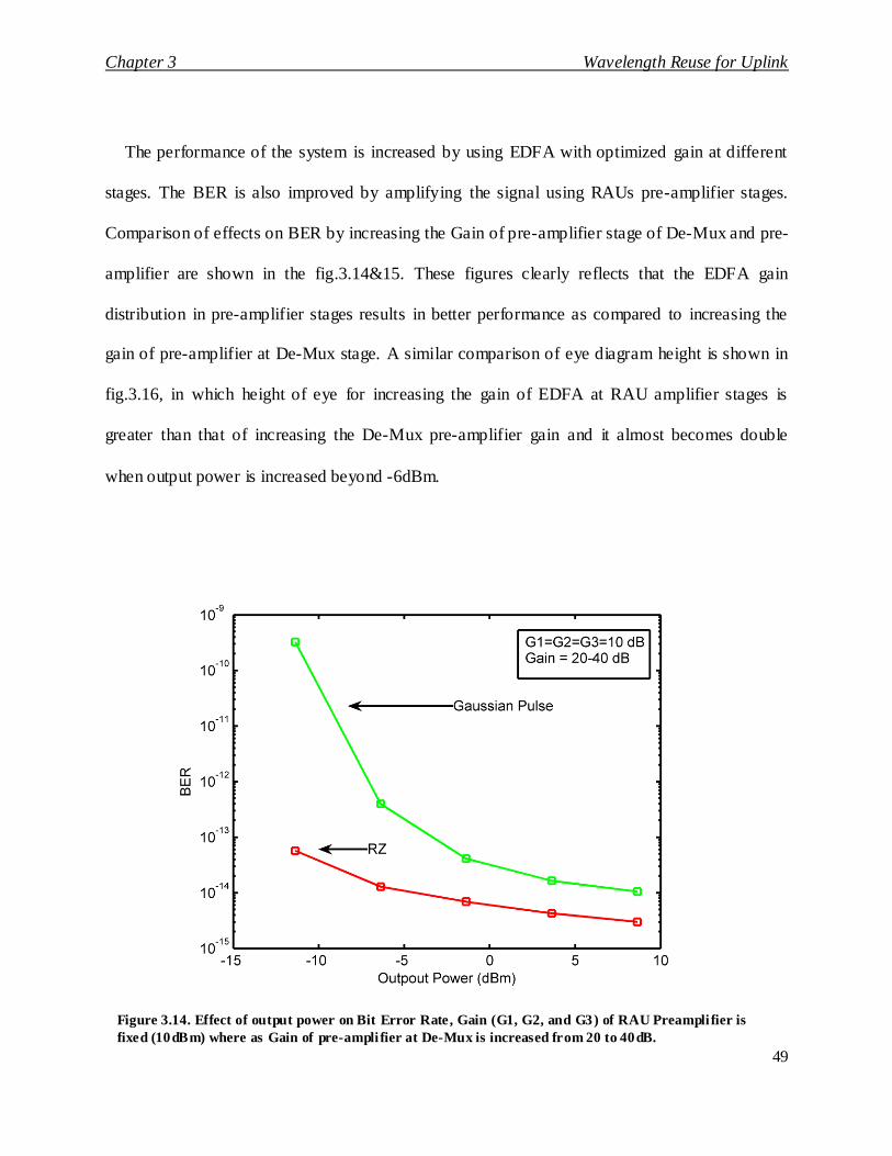
The performance of the system is increased by using EDFA with optimized gain at different
stages. The BER is also improved by amplifying the signal using RAUs pre-amplifier stages.
Comparison of effects on BER by increasing the Gain of pre-amplifier stage of De-Mux and pre-
amplifier are shown in the fig.3.14&15. These figures clearly reflects that the EDFA gain
distribution in pre-amplifier stages results in better performance as compared to increasing the
gain of pre-amplifier at De-Mux stage. A similar comparison of eye diagram height is shown in
fig.3.16, in which height of eye for increasing the gain of EDFA at RAU amplifier stages is
greater than that of increasing the De-Mux pre-amplifier gain and it almost becomes double
when output power is increased beyond -6dBm.
Figure 3.14. Effect of output power on Bit Error Rate, Gain (G1, G2, and G3) of RAU Preampli fier is
fixed (10dBm) where as Gain of pre-ampli fier at De-Mux is increased from 20 to 40dB.

Chapter 3 Wavelength Reuse for Uplink
50
Figure 3.15. Effect of output power on Bit Error Rate, Gain of RAU preamplifier is
increased where as Gain of pre-amplifier at De-Mux is decreased from 20 to5 dB.
Figure 3.16. Effect of output power on Eye height, Gain of RAU preamplifiers denoted as
G1, G2, G3 where as Gain of pre -amplifier at De-Mux is denoted as Gain.

Chapter 3 Wavelength Reuse for Uplink
51
3.7 Conclusion
DWDM based Radio over Fiber down link based on photonic generation and uplink based
on wavelength reuse can be deployed to increase the capacity of the DWDM-ROF systems.
System is flexible in terms of operating frequency and number of RAUs as number of RAUs can
be increased or decreased by adding or decreasing the operating wavelengths. Similarly, as
operating frequency is depending on the DWDM wavelengths, same can be configured on any
RAU using optical layer. This method will simplify the architecture of RAUs, as the number of
lasers used to design the overall system is reduced, however, the gain adjustment of EDFAs is
the basic requirement and if the gain is not adjusted properly, the bit error rate will increase. It
has been verified that the proper placement of EDFAs and gain optimization can result in good
performance. Further work will be done to apply this scheme in existing Radio over Fiber
networks, UWB radio and Next Generation Optical Systems to verify the performance and
compatibility of the scheme.
References
[1] Xiaoqiong Qi, Jiaming Liu, Xiaoping Zhang, and Liang Xie, ―Fiber Dispersion and
Nonlinearity Influences on Transmissions of AM and FM Data Modulation Signals in Radio-
Over-Fiber System‖ IEEE Journal of Quantum Electronics, Vol. 46, No. 8, 2010.
[2] Ateeq Mumtaz, M.K. Islam, M. Zafrullah, ―Photonic Signal Generation with Frequency
Hopping for DWDM based Radio over Fiber Systems‖, ICAIT, 2010.

Chapter 3 Wavelength Reuse for Uplink
52
[3] Toshiaki Kuri, Hiroyuki Toda, Juan Jose, Vegas Olmos and Ken- ichi Kitayama,
―Reconfigurable Dense Wavelength-Division-Multiplexing Millimeter-Waveband Radio-
Over-Fiber Access System Technologies‖ Journal Of Lightwave Technology, Vol. 28, No.
16, 2010.
[4] Stephen Pinter and Xavier Fernando, ―Radio over Fiber Systems for Broadband Wireless
Access‖, PHOTONS, the technical review magazine of the Canadian Institute of Photonic
Innovations (CIPI), 2004.
[5] Chun-Ting et. al , ―Hybrid Optical Access Network Integrating Fiber-to-the-Home and
Radio-Over-Fiber Systems‖, , IEEE Photonics Technology Letters, 2007
[6] J. He , L. Chen, Z. Dong, S. Wen, J. Yu, ―Full-duplex radio-over- fiber system with photonics
frequency quadruples for optical millimeter-wave generation‖ Optical Fiber Technology,
Vol. 15, 2009
[7] Lin Chen, Yufeng Shao, Xiaoyan Lei, Hong Wen, and Shuangchun Wen, ―A Novel Radio-
Over-Fiber System With Wavelength Reuse for Upstream Data Connection‖, IEEE
Photonics Technology Letters, Vol. 19, No. 6, 2007.
[8] L. Chen, J. Lu, J. He, Z. Dong and J. Y , ―A radio-over- fiber system with photonic generated
16QAM OFDM signals and wavelength reuse for upstream data connection‖, Optical Fiber
Technology, Vol. 15, Issue 3, 2009
[9] L. chen, J. Lu, Z.Dong, J.Yu, ―A radio-over-fiber system with photonics generated OFDM
signals and wavelength reuse for upstream data connection‖, ICAIT, 2008

Chapter 3 Wavelength Reuse for Uplink
53
[10] R.Shankar, M. Forjanczyk, T.J. Hall, A. Vukovic, Heng Hua ,‖Multi-degree ROADM
based on wavelength selective switches : Architecture and Scalability‖, Opt ics
Communications, 2007
[11] S. Azodolmolky, M. Klinkowski, Eva Marin, D.Careglio, J. Pareta, I.Tomkos, ―A survey
on physical layer impairments aware routing and wavelength assignment algorithms in
optical networks‖ Computer Networks, Vol.53, Issue.7, 13 May 2009
[12] Iyad Katib, Deep Medhi, ‖Adaptive alternate routing in WDM networks and its
performance tradeoffs in the presence of wavelength converters‖ Optical Switching and
Networking, Vol.6, Issue.3, 2009.
[13] Xiaowen Chu, Bo Li, ―Dynamic Routing and Wavelength Assignment in the Presence of
Wavelength Conversion for All-Optical Networks‖, IEEE/ACM Transactions on Networking
Vol. 13, No. 3, 2005.
[14] Poompat Saengudomlert, Eytan Modiano, and Robert G. Gallager, ―On-Line Routing
and Wavelength Assignment for Dynamic Traffic in WDM Ring and Torus Networks‖,
IEEE/ACM Transactions on Networking, Vol. 14, No. 2, 2006.

Chapter 4 UWB Signal Generation
54
Chapter 4 UWB Signal Generation
4.1 Introduction This chapter presents a simple technique for generation of Impulse Radio Ultra-wideband pulses in
optical domain. This system can transmit the data in Giga-bits-per-second range for 32 users across an
optical fiber link using Dense Wavelength Division Multiplexing (DWDM). A multiple access
technique using Direct Sequence Ultra-wideband (DS UWB) pulses has also been presented. Moreover,
the relationship between the input data rate and signal bandwidth has been analyzed and also studied the
effect of pulse width on the bandwidth of a signal.
Ultra-wideband (UWB) is an up-and-coming technology in wireless communication that has the
potential to provide high data rate broadband wireless access. Though it is an emerging technology at
present, the concept is not new at all. The history of using UWB for wireless communication goes back
to early 1900s when Marconi used UWB pulses in his spark-gap radio transmitter to transmit Morse
code sequences. The prominent qualities of UWB attracting attention of researchers from around the
globe are its low complexity, low cost, reduced power consumption and increased data rate. The mere
limitation of UWB is its short range which can be overcome by the use of Radio over Fiber technology
[1]-[4] entailing the use of Optical Fibers to carry signals from the head-end to user premises. This
technology is commonly referred to as UWB-over-fiber.
The generation of UWB pulses has always been a challenge because the wide bandwidth requires
the signal to be considerably narrow in the time domain. Moreover, to fully exploit the advantages of
UWB, there is a need for optical generation of UWB pulses to avoid the use of high cost electrical

Chapter 4 UWB Signal Generation
55
components, required to produce such narrow signals and to exceed the speed limitations offered by the
electrical components. Numerous solutions have been proposed in the past demonstrating all-optical
generation of UWB pulses. Recent approaches include the use of cross phase modulation [5], cross-gain
modulation in a semiconductor optical amplifier (SOA) [6], intensity modulator to generate polarity
switchable UWB pulses [7], LiNbO3 Intensity modulator using the transfer function‘s wavelength
dependant characteristics [8] and the use of Phase Modulator and asymmetric Mach-Zehnder
interferometer (AMZI) to generate UWB pulses [9]. The problem associated with phase modulation
and gain modulation [5] and [6] is that they require two laser sources resulting in increased system
complexity. In [7] and [8], the generation is limited to a single UWB pulse which confines the use o f
this technique to a limited number of applications. Also, the requirement of two wavelengths in [4]
renders the system expensive and complicated while [9] requires two Asymmetric Mach-Zehnder
interferometers (AMZIs) to be cascaded which causes the design to face stability issue.
A Mach-Zehnder modulator is used to modulate electrical Gaussian pulses. An optical delay line
followed by a subtractor is used to differentiate the optical Gaussian pulses and thus Ultra-wideband
monocycle pulses are generated. Owing to the use of optical components only, this technique results in
an ultrafast optical pulse source. In addition, we present a simple technique for the transmission of
optically generated Direct Sequence (DS) UWB and the provision of multiple-access capability in future
high speed wireless network.
4.2 UWB Monocycle Generation The schematics of the proposed design are shown in fig.4.1. The electrical Gaussian pulses are
generated from the incoming data by the help of a Gaussian pulse generator. These electrical pulses
modulate a Mach-Zehnder modulator and optical Gaussian pulses are produced.

Chapter 4 UWB Signal Generation
56
Mathematically, the Ultra-wideband monocycle pulse is given by the first order differential of a
Gaussian pulse. The width of resultant UWB pulse can be adjusted by manipulating the input Gaussian
pulse. In our design, differentiation is performed by splitting the optical Gaussian pulse into two equal
components. One component is passed through an optical delay line, delaying the signal in time by an
amount equal to one half of the width of Gaussian pulse. Then a subtractor is used to relate the later
component with the former. In this way, during the time in which the non-delayed component goes
through its ascending values, represented by section 1 in fig.4.2, the delayed component is zero and the
subtraction results in nothing but the non-delayed component itself.
Next, during section 2 in fig.4.2 the subtraction results in the values forming section 5 in the UWB
monocycle. During the section 3 of subtractor, the non-delayed Gaussian pulse has a constant value, thus
the correlation of the delayed component with this constant value results in an inverted copy of the
delayed component (section 6), producing UWB pulse in optical domain. The working of the
differentiator is demonstrated in fig.4.2. The delayed and non-delayed components are shown and
formation of UWB monocycle is depicted. As an application of the fore-mentioned technique we
provide an example of a high speed wireless communication system where multiple-access technique is
required to distinguish users on a common medium.
Sharing signals have important applied applications in various disciplines such as automobile anti-
collision system for expressway, satellite communication and location among satellite formation. [10-
12].

Chapter 4 UWB Signal Generation
57
Fig. 4.1. Schematic Diagram of the Proposed Solution
Fig. 42. Working of a Differentiator

Chapter 4 UWB Signal Generation
58
Assume that user 1 is transmitting a 0, user 2 is also transmitting a 0 and user 3 transmitting
a 1, represented by a -1, -1 and 1 respectively. The spreading code for user 1, user 2 and user 3 is
[1 1 1 1], [1 0 1 0] and [1 0 0 1] respectively. Upon multiplication of user input with their
corresponding orthogonal codes and subsequent summation, the waveform obtained to be
transmitted over the optical fiber is shown in fig.4.3.
This waveform modulates a Gaussian pulse train as shown in fig 4.4. The Gaussian pulse
train must be synchronized with the data rate of the input for proper amplitude modulation of the
pulses.
The modulated Gaussian pulse train is then used to generate UWB monocycle pulses in the
optical domain through the above discussed generation mechanism. The UWB p ulses carrying
the cumulative data of multiple users are shown in fig.4.5. The amplitude of the UWB
monocycles corresponds to the amplitude of cumulative waveform carrying user data while the
occurrence of positive and negative lobes corresponds to the polarity of the cumulative
waveform.
Fig. 4.3. Summation of spread bit streams

Chapter 4 UWB Signal Generation
59
Fig.4.4. Modulated Gaussian pulse train
Fig.4.5. Modulated UWB monocycle pulses

Chapter 4 UWB Signal Generation
60
4.3 Simulations and results
The discussed design is simulated at an input data rate of 2 Gbps. The optical delay line
used for the differentiation of Gaussian pulses has an inversely proportional relationship with
input data rate. The input data rates corresponding to the optical delay required for proper
differentiation are listed in Table-4.1. The value of optical delay can be calculated from the data
rate and width of the Gaussian pulse. For example, if the input data rate is 2 Gbps, the width of a
single bit comes out to be 1/(2*109) = 0.5 ns. So, if the Gaussian pulses are configured to be 0.1
bit wide, the width of the pulses in nanoseconds comes out to be 0.5*0.1 = 0.05 ns. Practically,
due to limitations of the Gaussian pulse generator, the actual width is twice this value i.e. 2*0.05
= 0.1 ns. Hence, at a data rate of 2 Gb/s, an optical delay line of 0.05 ns (one half of Gaussian
pulse width) is required for proper differentiation. From these calculations we can derive an
equation to calculate the value of optical delay line ‗D‘ from the data rate ‗R‘ and pulse width
‗W‘.
(4.1)
UWB pulses generated using On-Off keying at 2 Gbps and the corresponding frequency
spectrum are shown in fig.4. 6 & 7 respectively.
For comparison, the simulation has also been performed at a data rate of 1 Gbps. With the
data rate reduced to one half, the inverse proportional relationship dictates us to double the
optical delay offered. The required optical delay comes out to be 0.05*2 = 0.1ns which can be

Chapter 4 UWB Signal Generation
61
verified from table-4.1. The UWB monocycle produced and the corresponding frequency
spectrum, at an input data rate of 1 Gbps is shown in fig.4.8 & 9.
TABLE 4.1 DATA RATES CORRESPONDING TO REQUIRED DELAY
Sr. No. Data Rate (Gb/s) Optical Delay (ns)
1. 0.5 0.2
2. 1 0.1
3. 2 0.05
4. 4 0.025
Fig.4. 6. UWB monocycle generated at 2 Gb/s.

Chapter 4 UWB Signal Generation
62
The width of the UWB monocycle in figure 4.6 is 0.2 ns while it is 0.4 ns in figure 4.8. These
widths are twice the widths of the Gaussian pulses used to generate them. With the data rate
reduced to one half, the width of the pulse in time domain in doubled. Intuitively, this should
have an effect on the corresponding bandwidths of the pulses as well. From fig.4.7 and 9 we can
derive conclusions that there is a direct proportionality between the input data rate and UWB
pulse bandwidth. Doubling the data rate doubles the bandwidth. This relationship is shown in
Fig.4. 7. Frequency s pectrum of UWB monocycle at 2Gb/s. The spectrum is
centered at 5 Ghz and has a bandwidth of 6 GHz at -10dbm.

Chapter 4 UWB Signal Generation
63
the form a graph for two different values of Gaussian pulse width used for UWB monocycle
generation in fig.4.10.
Fig.4.8. UWB monocycle generated at 1 Gb/s. (Twice the pulse
width at 2 Gb/s)
Fig. 4.9. Frequency spectrum of UWB monocycle at
1Gb/s. The spectrum is centered at 2 GHz and has a
bandwidth of 3 GHz at -10dbm.

Chapter 4 UWB Signal Generation
64
It is clear from the graph that increasing the width of Gaussian pulse, reduces the
bandwidth of output UWB pulse, while the directly proportional relationship between input data
rate and bandwidth stays the same. This is in compliance with the fact that, shorter the pulses in
time domain, broader are their frequency spectra.
The output of Dense Wavelength Division Multiplexing is shown in fig.4.11. The UWB
pulses carrying the data of 32 different users are multiplexed using a frequency spacing of 100
GHz or a wavelength spacing of 0.8 nm. The shape of the signal for one user after travelling over
a 1 km optical fiber link with an attenuation of 0.2 dB/km and dispersion of 16.75 ps/(nm.km) is
shown in fig.4.12. The signal is received using a PIN photo diode.
Fig.4.10. Relationship between input data rate and bandwidth for two di fferent
values of Gaussian pulse width used.

Chapter 4 UWB Signal Generation
65
Fig.4.11. 32 Dense Wavelength Division Multiplexed channels
Fig.4.12. Shape of the UWB monocycle received after passing through 1 km
of optical fiber links
Wavelength (m)

Chapter 4 UWB Signal Generation
66
4.4 UWB Doublet and Triplet
UWB pulses are generated by a UWB pulse generator shown in fig.4.13. Monocycle,
doublet and triplet are generated by the UWB pulse generator stages. At first stage, monocycle is
received. This monocycle is generated by splitting input light into two equal parts and then
providing optical bias to one signal and delay to other. A subtractor is used to take the difference
of power. Doublet is generated by again splitting the signal genera ted by first stage and then
providing the bias and delay to one part of the spitted signal and then taking the difference of
both parts. Triplet is also generated from doublet using the same procedure as shown in fig.4.13.
Fig.4.13. UWB pulse generator
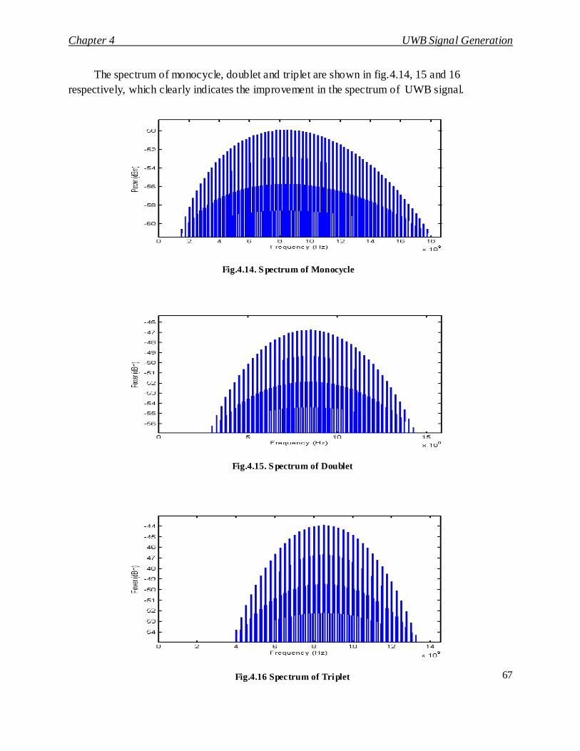
Chapter 4 UWB Signal Generation
67
The spectrum of monocycle, doublet and triplet are shown in fig.4.14, 15 and 16
respectively, which clearly indicates the improvement in the spectrum of UWB signal.
Fig.4.14. S pectrum of Monocycle
Fig.4.15. S pectrum of Doublet
Fig.4.16 Spectrum of Triplet

Chapter 4 UWB Signal Generation
68
4.5 UWB DWDM Ring
DWDM based UWB rings are shown in fig.17. Three rings are presented in this architecture.
In Ring#1 and 2, four nodes are configured; however, in ring 3, 8 nodes are designed. Each ring
is based on single mode fibers. Same fiber is used for uplink and downlink. In each ring, the
architecture of only one node is shown to keep the schematic simplified. Optical Add Drop
Multiplexers are used to drop and insert the wavelengths. At each site, one wavelength
modulated with downlink data is dropped and one with uplink data is inserted. The dropped
wavelength is converted into electrical signal using photodetector.
Uplink signal received from antenna is used for modulation of light using MZM. On CS, UWB
block is used to generate the modulated UWB pulses as per required pattern. Continuous light
generated by laser is modulated by MZM, which is then fed to UWB pulse generator. Output of
this pulse generator is connected to DWDM multiplexer where it is multiplexed and launched into
fiber.
DWDM block contains multiplexers and demultiplexers, which are operating independently for
different rings. Spectrum of signal launched in ring#2 and ring#3 is also shown in fig.4.18 & 19.
The spectrum of ring#1 is same as ring#2. In simple, this scenario, same wavelengths used in one
ring, can be reused in other rings as these wavelengths are being routed independently.
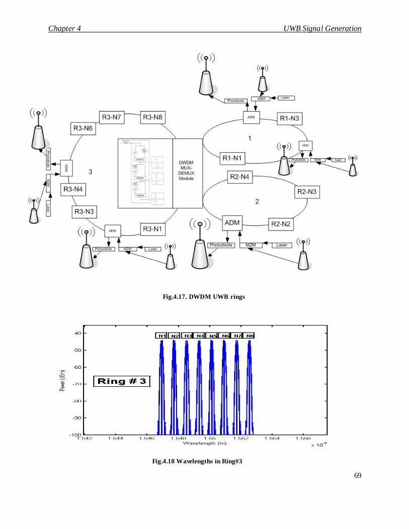
Chapter 4 UWB Signal Generation
69
Fig.4.17. DWDM UWB rings
Fig.4.18 Wavelengths in Ring#3
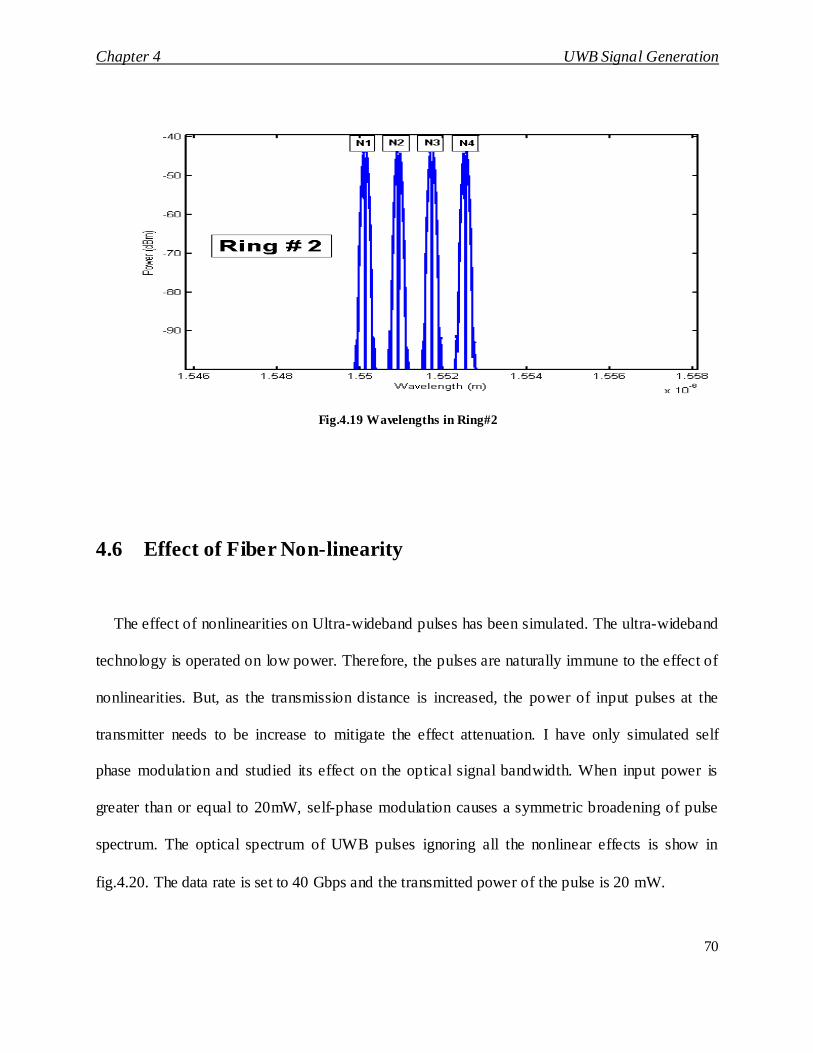
Chapter 4 UWB Signal Generation
70
4.6 Effect of Fiber Non-linearity
The effect of nonlinearities on Ultra-wideband pulses has been simulated. The ultra-wideband
technology is operated on low power. Therefore, the pulses are naturally immune to the effect of
nonlinearities. But, as the transmission distance is increased, the power of input pulses at the
transmitter needs to be increase to mitigate the effect attenuation. I have only simulated self
phase modulation and studied its effect on the optical signal bandwidth. When input power is
greater than or equal to 20mW, self-phase modulation causes a symmetric broadening of pulse
spectrum. The optical spectrum of UWB pulses ignoring all the nonlinear effects is show in
fig.4.20. The data rate is set to 40 Gbps and the transmitted power of the pulse is 20 mW.
Fig.4.19 Wavelengths in Ring#2

Chapter 4 UWB Signal Generation
71
Fig.4.20. S pectrum with zero SPM
Fig.4.21. S pectrum with SPM effects.
Fig.4.22. SPM effects without adjusting the dis persion of fiber

Chapter 4 UWB Signal Generation
72
With the introduction of self phase modulation, the UWB optical pulse spectrum broadens
symmetrically on both sides as shown in fig.4.21. Careful selection of the factors like core
effective area and power can help to mitigate the effect of SPM. Increasing the transmitted
power or length of the optical fiber has an adverse effect on SPM. These effects are depicted in
fig.4.22.
The longer the transmission distance, more is the power required at the transmitter output. The
effect of SPM is dependent upon the intensity of the pulses propagating through fiber. Larger
core area also reduces the pulse intensity propagating through optical fiber and hence decreases
the effect of SPM, similarly dispersion in optical fiber can be adjusted to counter and further
reduce the effect of SPM. The spectrum of UWB pulse after the introduction of dispersion in
fiber is shown in figure 4.23.
Fig. 4.23. SPM effects by adjusting the dispersion of fiber

Chapter 4 UWB Signal Generation
73
4.7 Conclusions A simple technique for optical generation of Impulse radio UWB pulses was presented along
with the mechanism to transmit the data of 32 users over an optical fiber link using Dense
Wavelength Division Multiplexing. The use of optical components to generate UWB pulses
allows exceeding the limitations of electrical components and high data rates can be achieved. It
has been found that the bandwidth available is directly proportional to the input data rate.
UWB radio systems can be used with DWDM to effectively utilize the bandwidth and other
advantages of optical fiber. The presented method can be used with existing DWDM systems.
Single UWB method can be used to generated monocycle, doublet and triplet depending on the
requirement of the system. SPM effects in DWDM UWB can be decreased by selecting the
optimized dispersion profile. This scheme can be used to design an integrated DWDM ROF
UWB system.
References
[1] Xiaoqiong Qi, Jiaming Liu, Xiaoping Zhang, and Liang Xie, ―Fiber Dispersion and
Nonlinearity Influences on Transmissions of AM and FM Data Modulation Signals in Radio-
Over-Fiber System‖ IEEE Journal of Quantum Electronics, Vol. 46, No. 8, 2010
[2] Ateeq Mumtaz, M.K. Islam, M. Zafrullah, ―Photonic Signal Generation with Frequency
Hopping for DWDM based Radio over Fiber Systems‖, ICAIT, 2010.

Chapter 4 UWB Signal Generation
74
[3] Toshiaki Kuri, Hiroyuki Toda, Juan Jose, Vegas Olmos and Ken- ichi Kitayama,
―Reconfigurable Dense Wavelength-Division-Multiplexing Millimeter-Waveband Radio-Over-
Fiber Access System Technologies‖ Journal Of Lightwave Technology, Vol. 28, No. 16, 2010.
[4] J. He , L. Chen, Z. Dong, S. Wen, J. Yu, ―Full-duplex radio-over- fiber system with photonics
frequency quadruples for optical millimeter-wave generation‖, Optical Fiber Technology Vol.
15, 2009.
[5] F. Zeng, Q. Wang and J. Yao, ―All-optical UWB impulse generation based on cross-phase
modulation and frequency discrimination‖, Electronics Letters, 18th January 2007, Vol. 43 No.
2.
[6] Wang, Q., Zeng, F., Blais, S., and Yao, J., ―Optical ultrawideband monocycle pulse
generation based on cross-gain modulation in a semiconductor optical amplifier‖, Opt. Lett.,
2006, 31, pp. 3083–3085.
[7] Q. Wang and J. Yao, "UWB doublet generation using nonlinearly-biased electro-optic
intensity modulator," Electron. Lett. 42, (2006), 1304—1305.
[8] J. Q. Li, S. N. Fu, K. Xu, J. Wu, J. T. Lin, M. Tang, and P. Shum, "Photonic ultrawideband
monocycle pulse generation using a single electro-optic modulator," Opt. Lett., vol. 33, no. 3, pp.
288-290, Feb. 2008Opt. Lett. 33, 288 (2008).
[9] S. Pan and J. P. Yao: ―Switchable UWB pulse generation using a phase modulator and a
reconfigurable asymmetric Mach-Zehnder interferometer‖, Opt. Lett. 34, 160 (2009).
[10] R.J. Fontana, Microwave Theory and Techniques, 9,p.2087(2004).

Chapter 4 UWB Signal Generation
75
[11] A. Widodo, T. Hasegawa, 5th Spread Spectrum Techniques and Applications,
p.82(1998).
[12] Wang shilian, Zhang eryang, ―Inter-satellite radio links and spread-spectrum ranging for
satellite formation flying‖ 3rd ICMMT 2002, p.233(2002).

Chapter 5 NEXT GENERATION MULTI-SERVICE ACCESS GATEWAY
76
Chapter 5 Next Generation Multi-Service Access Gateway
5.1 Introduction
In this Chapter, we have presented a Next Generation Multi-Service Access Gateway (NG-
MSAG) for Radio over Fiber (ROF) systems. The architecture of this NG-MSAG allows the
convergence of fixed, wireless, voice and data services. This convergence will decrease the
overall deployment and operational cost of telecom operators especially those operators which
are new in the industry and interested in deploying nation-wide fixed and wireless networks.
Transport layer is based on IP/DWDM, Radio layer on ROF and services core is based on NGN.
Radio over Fiber can be used to completely centralize the radio resources like modulation,
demodulation and radio resource management to Central Station (CS) while deploying Remote
Antenna Units (RAU) at different locations [1-3]. We have presented solutions for generation of
radio signals [4-5] in optical domains for wireless ROF systems. However, the work was only
related to generation of ASK and UWB signals in optical fiber. We have presented an
integration of Radio over Fiber with Next Generation Networks (NGN). NGN is already
deployed by most of the telecom market leaders. In normal telecom NGN architecture, media
gateways (MG) and multi-service access gateways (MSAG) are used to provide fixed telecom
services [6-9], whereas for wireless services BTSs are deployed. These BTSs are connected with
BSC using optical fiber or microwave links.
In this chapter, we have incorporated a radio services capability in multi service access gateways.
This NG-MSAG architecture can be deployed with both TDM based MSC and Mobile Soft

Chapter 5 NEXT GENERATION MULTI-SERVICE ACCESS GATEWAY
77
Switch (MSS). It can also support fixed services like Basic Voice Service, Broadband Internet
(DSL) and IPTV. No additional BTS is required in this case as NG-MSAG will serve the
required area for both fixed and wireless services. NG-MSAG has remote antenna unit to feed
the antenna. Radio over fiber based Passive Optical Network (PON) can also be used to further
split the cells into pico-cells, if required. Optical transport layer is based on IP/DWDM which
can directly support TCP/IP traffic over wavelengths in addition to normal traffic. Erbium Doped
Fiber Amplifiers (EDFAs) can also be used to amplify the signal.
This NG-MSAG can be deployed in very short period of time as it is compact and does not
require a complex infrastructure as most of the complex functionalities are already shifted to CS.
NG-MSAG can also be connected with IMS by using SIP between NG-MSAG and IMS.
5.2 Architecture of NG-MSAG
In ROF, no modulator and demodulator is required at RAU. The architecture of NG-MSAG
is shown in fig.5.1. Radio Services Module (RSM) is used for wireless services. Control unit is
responsible for control, configuration and management of all modules. DSL/IPTV module is
used for provision of DSL and IPTV services. PSTN module is used for provision of traditional
voice and telephony services, however, it is based on VoIP and this module acts as VoIP
gateway. RSM incorporates the main functionality of wireless services which enables the NG-
MSAG to be used as BTS.
Optical Add Drop Multiplexer (OADM) with capability to add-drop two wavelengths is
used. One wavelength is routed to RSM, whereas, the second wavelength is connected to
router/switch which is further connected with DSL/IPTV and PSTN modules. In RSM, shown in

Chapter 5 NEXT GENERATION MULTI-SERVICE ACCESS GATEWAY
78
the architecture, the dropped wavelength is connected to photodiode, which converts the optical
signal into electrical. The converted signal is filtered, amplified and transmitted by using
antenna. Uplink architecture of RSM is not shown in figure as it only converts the uplink signal
into light by using laser and MZM and then transmits to CS using OADM.
Fig.5.1 Architecture of NG-MSAG
5.3 Connectivity of NG-MSAG with Core network
NG-MSAG is connected with all telecom core network elements. It is connected with Soft-
Switch (SS) by using IP cloud and controlled by H.248. For DSL and IPTV services, it will have
connectivity with DSL/IPTV core platforms and for wireless services it will be connected with
Central Station which will be co- located with BSC or integrated with BSC. The connectivity
NG-MSAG
Control Unit
OADM
IPTV/
DSL
Router/Switch
Filter
RSM
PS
TN
(PO
TS
)
DS
L/IP
TV Voice
Photodiode
EA

Chapter 5 NEXT GENERATION MULTI-SERVICE ACCESS GATEWAY
79
diagram of NG-MSAG is shown in the fig.5.2. For simplicity, only four nodes are shown
however they can be increased depending on the wavelength capacity of DWDM system. In this
scenario, only eight wavelengths are simulated. These wavelengths at the output of DWDM
MUX and input of first NG-MSAG are shown in fig.5.3&4. RSM module has an internal
amplifier and can directly feed antenna.
Antenna is connected with the output port of NG-MSAG and used for wireless services. If
the outgoing call belongs to some other operator or network it is routed via Media-Gateway
(MG).
For soft-phone users SIP will be used [9]. DSL and IPTV services are routed to DSL/IPTV
core platform depending on their VLANs. This scenario is already implemented in existing
networks however additional RSM will redesign the whole infrastructure and all wireless
calls/data are routed via NG-MSAG.
Wireless calls are received by antenna at the top of NG-MSAG, converted into light and
transmitted to CS on Single Mode Fiber (SMF). No de-modulation is done at NG-MSAG as the
signal is demodulated by CS. CS handovers the call to BSC where it is routed to the MSC for
further processing.
In case of wireless data services, like EVDO, again the same flow is adapted from RSM to
CS, however, the call is routed to PDSN using IP Core where after authentication from AAA
servers, the data is routed to Internet.

Chapter 5 NEXT GENERATION MULTI-SERVICE ACCESS GATEWAY
80
Fig.5.2. Connectivity of NG-MSAG with Core Network
Fig.5.3. DWDM signal at the output of DWDM MUX
Fig.54. DWDM signal at the input of NG-MSAG OADM

Chapter 5 NEXT GENERATION MULTI-SERVICE ACCESS GATEWAY
81
5. 4 Simulation results and discussion
We simulated the optical layer of NG-MSAG network shown in fig.5.2. In this simulation,
only four NG-MSAGs are simulated to keep the simulation simplified. Eight wavelengths are
used for DWDM with each having separation of 100 GHz. At each node two wavelengths are
dropped, one for radio services and one for fixed services. At central station 8 lasers are operated
at the required wavelengths with input power of 1mW. MZM is used to modulate the light by
electrical signal. Two wavelengths are reserved for each site, first wavelengths is used for RSM
whereas second one is shared by remaining modules of the NG-MSAG.
Fixed services are simulated by a stream of data whereas ASK and PSK are simulated for
wireless services. Input data stream for fixed services is shown in fig.5.5. In this simulation, first
laser is modulated with ASK signal, shown in fig.5.6, and second laser with digital data stream.
These two signals are required to be transmitted to first NG-MSAG. Third laser is simulated with
PSK shown in fig.5.7, and fourth again with the digital data stream of that respective MSAG and
required to be dropped at second NG-MSAG. DWDM MUX is used to multiplex all these eight
wavelengths. The spectrum of signal is shown in fig.5.3.
Fig.5.5 Input data stream, simulated as IP data
Fig.5.6. AS K signal used for modulation of first laser
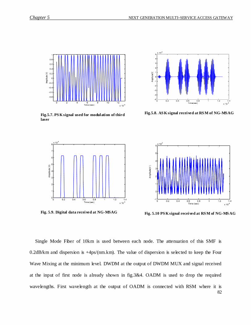
Chapter 5 NEXT GENERATION MULTI-SERVICE ACCESS GATEWAY
82
Single Mode Fiber of 10km is used between each node. The attenuation of this SMF is
0.2dB/km and dispersion is +4ps/(nm.km). The value of dispersion is selected to keep the Four
Wave Mixing at the minimum level. DWDM at the output of DWDM MUX and signal received
at the input of first node is already shown in fig.3&4. OADM is used to drop the required
wavelengths. First wavelength at the output of OADM is connected with RSM where it is
Fig.5.7. PS K signal used for modulation of third
laser
Fig.5.8. AS K signal received at RS M of NG-MSAG
Fig. 5.9. Digital data received at NG-MSAG
Fig. 5.10 PS K signal received at RS M of NG-MS AG

Chapter 5 NEXT GENERATION MULTI-SERVICE ACCESS GATEWAY
83
converted into electrical signal by using Photodetector. Noise in the received signal is filter by
using a band-pass filter and the signal at the output of filter is shown in fig.5.8. Similarly, second
wavelength of first node is converted into electrical signal (fig.5.9.) and routed to the required
modules depending upon the IP addresses. On second node the same scheme is used to convert
the signal. The received PSK signal is also shown in fig.5.10. We have simulated ASK and PSK
modulation schemes, however, this solution is independent of modulation scheme and can be
deployed with all major wireless services.
5. 6 Performance analysis
In the simulation, only four NG-MSAGs are simulated, however, there will be no effect of
increasing the NG-MSAGs on performance of system. Total number of NG-MSAG depends on
the total available DWDM wavelenlenghts. This kind of architecture has not been presented so
far, so it is difficult to exactly compare the performance with any existing scenario, however, we
have done different simulation for different data rates and tranmission impairments to find the
optimized values for our scheme. Dispersion of Single Mode Fiber is incresaed from 0 to +17
ps/(nm.km) and it has been verified that the optimized value of dispersion for best performace is
+2 to +4 ps/(nm.km). Similarly, distance of last NG-MSAG has been incresaed from 10 km to
100km with fiber attenuation of 0.2 db/km, and the simulation results verify that the distance of
last NG-MSAG from CS can be easily increased upto distance of 100 km.

Chapter 5 NEXT GENERATION MULTI-SERVICE ACCESS GATEWAY
84
5.7 Conclusion Integration of ROF with DWDM and media gateways results in a single node (NG-MSAG)
with capability to support all modern fixed and wireless telecom services. This solution is based
on NGN and can also be integrated with IMS. Deployment time of telecom infrastructure is
decreased and plannig of NGN access network is simplified which resluts in a cost effective
solution for telecom operators. This is a complete architecture which can be deployed by any
operator to provide all fixed and wireless, voice and data services.
References
[1] X.Qi, J.Liu, X.Zhang, and L..Xie, ―Fiber Dispersion and Nonlinearity Influences on
Transmissions of AM and FM Data Modulation Signals in Radio-Over-Fiber System‖ IEEE
Journal Of Quantum Electronics, Vol. 46, No. 8, 2010
[2] T.Kuri, Hi Toda, Juan Jose, V.Olmos and K.Kitayama, ,―Reconfigurable Dense Wavelength-
Division-Multiplexing Millimeter-Waveband Radio-Over-Fiber Access System
Technologies‖ Journal Of Lightwave Technology, Vol. 28, No. 16, 2010
[3] J. He , L. Chen, Z. Dong, S. Wen, J. Yu, ―Full-Duplex Radio-Over-Fiber System With
Photonics Frequency Quadruples For Optical Millimeter-Wave Generation‖ Optical Fiber
Technology, VOL. 15, 2009
[4] Ateeq Mumtaz, M.K. Islam, M. Zafrullah, ―Photonic Signal Generation with Frequency
Hopping for DWDM based Radio over Fiber Systems‖, ICAIT, 2010

Chapter 5 NEXT GENERATION MULTI-SERVICE ACCESS GATEWAY
85
[5] Affan Hasan Khan, Omer Khalid, Ateeq Mumtaz, M. Khawar Islam, ―DWDM Based System
for Optical Generation and Transmission of Impulse Radio UWB Signals‖, IEEE, ICET,
2011
[6] Morita. N, ―Introduction to NGN Functional Architecture‖, Network Operations and
Management Symposium, 2006
[7] 3GPP and ITU working groups recommendation on VOIP and NGN
[8] Mohapatra, S.K, ―Integrated planning for Next Generation Networks‖Integrated Network
Management-Workshops, 2009
[9] Pirhadi, M. Hemami, S.M.S. Tabrizipoor, A.I., ―Call set-up time modeling for SIP-based
stateless and stateful calls in Next Generation Networks‖, Advanced Communication
Technology, ICACT 2009

Chapter 6 Conclusions
86
Chapter 6 Conclusions
Radio over Fiber provides an efficient optical layer for wireless services, by providing
increased bandwidth, reliability, network security, effective radio resource management,
increased capacity and flexible network architecture. In this thesis, different scheme for pho tonic
generation, frequency hopping, DWDM ROF system, Wavelength reuse, EDFA gain
optimization, UWB generation and Next Generation Radio over Fiber systems are presented.
Detailed simulations are carried out to verify these schemes and performance analysis is done to
verify the performance in the presence of transmission impairments. In this chapter, research
achievements have been summarized.
6.1 Summary of Accomplishments
1. The photonic generation of ROF signal by beating two wavelengths at photodiode is
simulated. Amplitude Shift Keying signal in the range of 60 GHz is successfully generated.
No electrical oscillator is used in this generation and the frequency of this signal can be
easily changed by changing the operating wavelength of one of the two lasers at the central
station.
2. Frequency hopping is proposed and simulated by using optical switch to shift the
wavelengths as per hopping sequence. Sequential and random slow hopping ca n easily be
achieved by this scheme. Different simulations are done to switch the operating frequencies
of the signals. This scheme is also compatible with DWDM as different scenarios are
successfully simulated.

Chapter 6 Conclusions
87
3. DWDM ROF rings using photonic generation are presented. Complete wavelength plan is
also presented which clearly provided the details of wavelengths management in DWDM
rings when photonic generation is used in DWDM systems.
4. Performance analysis of DWDM ROF system is done and optimized values of different
parameters have been achieved. Simulations results prove that 4Gbps can easily be
transmitted from CS to RAU up to distance of 100 km. Moreover, the best performance is
achieved when dispersion of fiber is optimized at 2 ~ 4 ps/(nm.km).
5. Wavelength reuses for uplink scheme at RAU is presented and power budget calculations
are done to optimize the gain. Different algorithms are proposed and simulated to adjust the
gain of EDFAs in DWDM rings. Extensive simulations are carried out to verify these
algorithms. Received power at RAU is successfully optimized using these algorithms and
wavelength is reused for uplink. In this scheme no laser is required at RAU. Wavelength
assignment and routing algorithm is also proposed.
6. DWDM rings with different RAUs are simulated by placing EDFA as per proposed
algorithms. Eye diagram analysis and bit error rate calculations are done to study the system
behavior, when wavelength is reused. Simulations results proved that by placing EDFA on
proper locations and gain adjustment the scheme can easily be used in DWDM ROF systems.
7. UWB signals are generated in photonic domain and pulse optimization is done to achieve the
monocycle for UWB signals. This generation is achieved by delaying one pulse and optical
biasing the other and then subtracting both signals. Application of this scheme in wireless
systems is also presented. Multi-UWB pulse generator for generation of monocycle, doublet
and triplet and the optimized bandwidth is also presented. Effect of non-linearities on the
systems is also studied.

Chapter 6 Conclusions
88
8. Next Generation Multi Service Access Gateway is presented for convergence of mobile and
fixed services. This NG-MSAG can provide both fixed value added and basis services along
with all mobile voice and data services. This is an integration of traditional optical fiber
system and radio over fiber system. This NG-MSAG is simulated and integrated with NG-
MSAG.
6.2 Future Work
Further work can be done to explore the field of photonic generation and methods for
generation of other modulation techniques and bandwidth optimization. Routing and
Wavelength assignment for radio over fiber is another field which required extensive research
work. The presented schemes in this thesis can be integrated with other schemes and existing
optical networks, however, it also requires further research and optimization in the presence of
transmission impairments.

89
List of Publications
1. Ateeq Mumtaz, M.K. Islam, M. Zafrullah, ―Wavelength Reuse for Uplink on Dense
Wave Division Multiplexing (DWDM) Single Fiber Ring for Radio over Fiber (ROF)
Broadband Systems with Downlink Signal Generation in Optical Domain‖, Journal of
Optical Engineering, USA, Vol. 50(10), October 2011
2. Ateeq Mumtaz, M.K. Islam, M. Zafrullah, ―Photonic Signal Generation with Frequency
Hopping for DWDM based Radio over Fiber Systems‖, IEEE ICAIT, 2010
3. Ateeq Mumtaz, Muhammad Khawar Islam, ―Next Generation Multi-Service Access
Gateway for Radio over Fiber Wireless Systems‖, IEEE ICET, 2011
4. Affan Hasan Khan, Omer Khalid, Ateeq Mumtaz, M. Khawar Islam, ―DWDM Based
System for Optical Generation and Transmission of Impulse Radio UWB Signals‖, IEEE
ICET, 2011
5. Ateeq Mumtaz, M.K. Islam, M. Zafrullah, ―Amplitude Shift Keying Radio Over Fiber
Dense Wavelength Division Multiplexed Signal Generation For Broadband Wireless
Access‖, (submitted journal paper)
6. Ateeq Mumtaz, M. Khawar Islam, Affan Hasan Khan, Omer Khalid, ‖Ultra Wide Band
Radio DWDM rings with photonic UWB pulse generation and transmission in presence
of non- linearities‖, IEEE IBCAST, 2012