assuring the integrity of air-cooled heat exchanger tube ... · 7 assuring the integrity of...
TRANSCRIPT
7
Assuring the Integrity of Air-cooled Heat Exchanger Tube to Tubesheet Welds
David Spencer
Dr. Jeremy Leggoe & Pr. Xiaozhi Hu School of Mechanical Engineering
Gordon Fuller & Darryl Godfrey CEED Client: BP Refinery Kwinana
Abstract
Air-cooled heat exchangers can be used for several applications on a crude oil refinery, one of the more common uses is for cooling process fluids. These heat exchangers are generally of a single pass design which consists of two large rectangular ‘header’ boxes, an inlet and outlet connected by a number of finned tubes with air blown past them by a fan. Due to the simultaneous failure of several welded tube to tubesheet joints in a set of high pressure heat exchangers at BP Refinery Kwinana, a better method of assuring the integrity of these joints is being explored. Investigations on samples of the failed header boxes concluded the damage mechanisms causing failure were a combination of corrosion and an environmentally induced cracking mechanism (Verbruggen, 2007). This created a desire for methods of obtaining two sets of joint quality information; a determination of the extent of the external corrosion of the joint, and a method of detecting any cracks originating from the inaccessible weld root. This project includes an investigation into the stress distribution in the joints by means of finite element analysis and testing on a sample header box manufactured to investigate the information that can be acquired utilising different Non-Destructive Testing (NDT) methods and devices.
1. Introduction 1.1 Air-Cooled Heat Exchangers Air-Cooled heat exchangers use finned tubes to transfer heat from a fluid contained in the tubes to air which is forced past by a fan. The most common applications for fin fan heat exchangers are process fluid coolers, condensers and air pre-heaters. This project is focussed on the connection between the finned tubes and the long rectangular fluid inlet/outlet boxes known as header boxes. These header boxes consist of a tubesheet, a plugsheet with top and bottom plates and end plates completing the box construction. There are also stay plates parallel to the top and bottom plates for structural integrity. The tubesheet is a usually steel plate with holes into which tubes are inserted then expanded and/or welded to create a sealed joint, the plugsheet has the same number of holes as the tubesheet but they are threaded and during operation are sealed using gaskets and removable plugs. These plugholes are the only inspection access after fabrication of the heat exchanger and are similarly the only access when joining the tubes to the tubesheet during fabrication as the header box is completely constructed and heat treated before the tubes are joined.
CEED Seminar Proceedings 2009 David Spencer: Heat Exchanger Joint Integrity Assurance
8
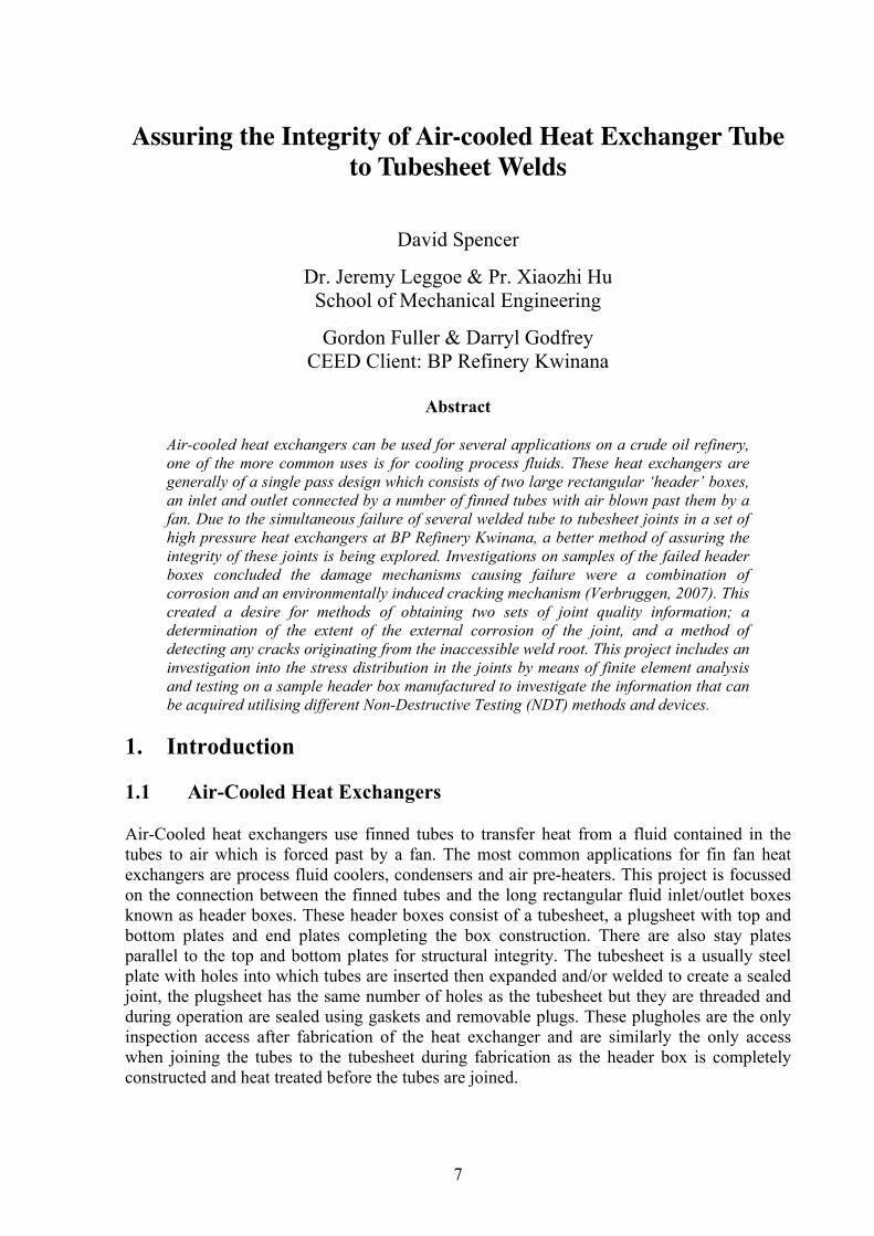
Figure 1: This diagram shows a single pass air-cooled heat exchanger tube
bundle and inlet/outlet header boxes, (American Petroleum Institute Standards, 2006).
These heat exchangers have highly varied operating conditions, particularly internal pressures and temperatures but also differing process fluids. Industry standards use these factors to determine the minimum specifications of the header box materials, thicknesses and tube to tubesheet joint types. 1.2 The Failure In June 2005 a set of air-cooled heat exchangers on the BP Kwinana Refinery suffered failures in several of the welds joining the tubes to the tubesheet. These heat exchangers were part of the Hydrofiner 2 processing unit, a ‘hydrotreating’ process unit which primarily removes sulphur from the stream by adding heat in the presence of hydrogen and a catalyst. This causes a reaction in which the sulphur from the stream is converted to gaseous hydrogen sulphide and is removed as part of the reactor effluent. These heat exchangers are used to cool a mixture of wash water and reactor effluent, this fluid is comprised of a variety of harmful and corrosive gases approximately 3% of which is Hydrogen Sulphide. In these heat exchangers the fluid is under high pressure, greater than 6300 kPa gauge pressure and up to 136 oC at the inlet side of the exchanger. In this and many other air-cooled heat exchangers on site the tubes have a 25.4 mm outer diameter, while the minimum diameter of the plugholes ranges from 24mm to 34mm depending on the type of tube to tubesheet joint. The heat exchangers with welded joints have the larger plugholes at minimum 34mm as these plugholes are not only used for inspection but also as access when welding the tube ends during manufacture, where smaller plugholes exist the tubes are usually only expanded into the tube holes. The magnitude of the internal pressure contained by these specific heat exchangers combined with a hazardous process fluid, causes the requirement for the thickness of the tubesheet and plugsheet to be 40mm, the tube end joint required is a seal weld. This creates problems during welding as a tubesheet of this thickness acts as a heat sink causing the welded steel to cool very quickly, dramatically increasing the final hardness of the weld. Cracks in individual tubes are reasonably common, and the action taken is to plug the tube ends to individually prevent flow through cracked tubes. This prevents leaking tubes and a hydrostatic test is then performed to assure the seal of the plugged tube. However in 2005 the cracks occurred in welds between the tube and tubesheet, making them undetectable by the Non-Destructive Testing (NDT) methods used and not treatable by plugging the tube end. This caused a lack of containment incurring significant financial penalties due to unit downtime and for the reduced production during the manufacture of new heat exchangers.
CEED Seminar Proceedings 2009 David Spencer: Heat Exchanger Joint Integrity Assurance
9
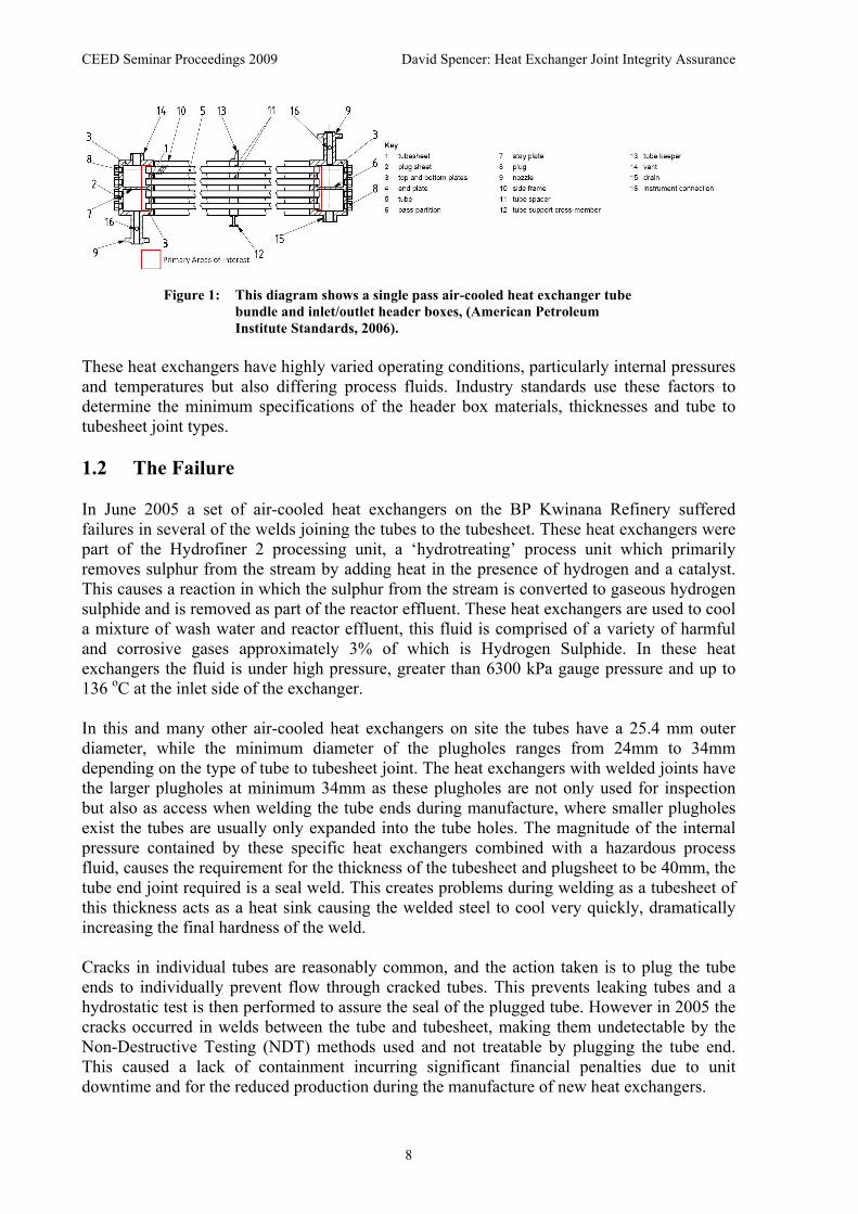
The failed heat exchangers were replaced by six new heat exchangers consisting of two new header boxes and 213 new tubes per exchanger. The new tube to tubesheet joints were upgraded from seal welds to multi-pass strength welds. The multi-pass welds have a lower hardness as the maximum temperature during welding is lower because the weld is split into multiple passes between which the joint is allowed to cool. The upgraded joints also required the tubes to be expanded into the tube hole behind the weld, this was to absorb stress caused by any tube vibration that would encourage the progression of cracks in the tube end welds. 2. Processes This project includes the use of several approaches and techniques to develop a successful solution to the situation including the development of a finite element model in order to analyse the stresses occurring in and around the tube to tubesheet joints. Also a sample header box was designed and fabricated as a part of this project, testing on this and a sample of a failed header box will assess the quality of the information that can be obtained utilising different inspection methods and devices. 2.1 Development of a Finite Element Model A finite element model has been created utilising Abaqus/CAE version 6.8. The Current model makes several broad assumptions including constant material density and stiffness. This model was created to get an idea of the magnitude of the stresses acting in the joint and their distribution during operation. In the model the weld is modelled by merging the element nodes, behind the 2mm deep weld there is a 0.1mm gap between the tube and tubesheet. The loads included in the model are the internal pressure which acts on the inner surface of the tube and the front face of the tubesheet. Gravity is modelled by applying a uniform load acting on the nodes of the tube which are unsupported by the tubesheet, creating an exaggerated gravity load. 2.2 Sample Header Box The Sample header box is not a closed box instead it has open ends and a detachable front face to allow testing on tube to tubesheet joints with and without the access constraints of the actual situation. The Sample header also provides a sample of the joints as they were before being commissioned for service, this enables a comparison between the joints at manufacture and failure. There are four different tube joints included on the sample representing the tube end joints found on air-cooled heat exchangers on the Kwinana Refinery. Each tube to tubesheet joint is modelled on two tube ends, the joints from left to right are; seal welded, strength welded and expanded, seal welded and expanded, expanded only.
Figure 2: This diagram shows a exploded schematic of the Sample header box.

CEED Seminar Proceedings 2009 David Spencer: Heat Exchanger Joint Integrity Assurance
10
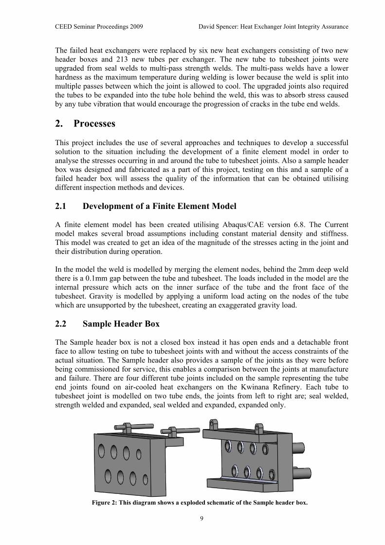
2.3 Non-Destructive Testing Investigation An investigation into NDT methods and equipment was undertaken to determine possible techniques for indicating the extent of joint corrosion and for detecting cracking originating at the weld root. The Potential techniques identified for crack detection were Radiography, Eddy current testing, Magnetic Particle Inspection, Ultrasonics, Dye Penetrant Testing and Vibration Sensitivity testing. All of these types of NDT are capable of detecting cracks however major issues were identified with each of these methods in attempting to detect the cracking occurring in this situation. Magnetic Particle inspection, Dye Penetrant and eddy current testing can only reliably detect surface cracks. This is a fatal flaw for this application as the surface from which the cracks are originating is completely inaccessible, as it exists approximately 38mm down a 1mm gap between a steel plate and tube. Radiographic, Ultrasonic and Vibration Sensitivity techniques are all capable of detecting non-surface cracking, due to the geometry of this application a meaningful Radiographic image is unobtainable. Ultrasonics presents several techniques often used for testing inside long tubes and thus access is not a major issue. Unfortunately the techniques used aren’t capable of reliably detecting cracks as the readings obtained are averaged over the tested area, usually of approximately a square centimetre. Vibration sensitivity crack detection requires previous knowledge of the modal frequencies of the entire heat exchanger, obtaining this information would require the construction of a very large and expensive model. This combined with the potential harm and detection reliability terminated investigation into this crack detection method. For assessing the extent of the corrosion of the tube end joint several potential techniques and devices were identified. Prior to the commencement of this project, a bore gauge was purchased in the hope that there may be detectable increase in tube bore readings. Another potential method identified was taking a measurable mould of a tube end joint capable of providing information on the geometry of the entire joint. Two other potential methods included the use of a pin profile gauge or laser profilometry technology in order to gain an accurate indication of the geometry of the tube to tubesheet joints. 3. Results and Discussion 3.1 Finite Element Analysis The results of analysis performed on the finite element model thus far have identified a stress concentration at the weld root, these results are consistent with the findings of examinations performed on samples of the failed header boxes (Verbruggen, 2006). The model can be further refined in multiple areas, one of these is modelling a local increase in hardness in and around the weld. Including this variable hardness or more loading conditions will increase the accuracy of the maximum stress estimation in the tube end joint.
CEED Seminar Proceedings 2009 David Spencer: Heat Exchanger Joint Integrity Assurance
11
Figure 3: This diagram shows the stress distribution around a tube end joint
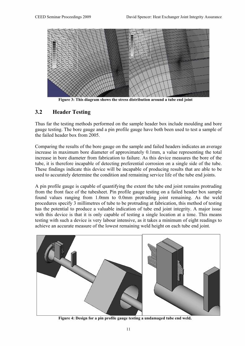
3.2 Header Testing Thus far the testing methods performed on the sample header box include moulding and bore gauge testing. The bore gauge and a pin profile gauge have both been used to test a sample of the failed header box from 2005. Comparing the results of the bore gauge on the sample and failed headers indicates an average increase in maximum bore diameter of approximately 0.1mm, a value representing the total increase in bore diameter from fabrication to failure. As this device measures the bore of the tube, it is therefore incapable of detecting preferential corrosion on a single side of the tube. These findings indicate this device will be incapable of producing results that are able to be used to accurately determine the condition and remaining service life of the tube end joints. A pin profile gauge is capable of quantifying the extent the tube end joint remains protruding from the front face of the tubesheet. Pin profile gauge testing on a failed header box sample found values ranging from 1.0mm to 0.0mm protruding joint remaining. As the weld procedures specify 3 millimetres of tube to be protruding at fabrication, this method of testing has the potential to produce a valuable indication of tube end joint integrity. A major issue with this device is that it is only capable of testing a single location at a time. This means testing with such a device is very labour intensive, as it takes a minimum of eight readings to achieve an accurate measure of the lowest remaining weld height on each tube end joint.
Figure 4: Design for a pin profile gauge testing a undamaged tube end weld.
CEED Seminar Proceedings 2009 David Spencer: Heat Exchanger Joint Integrity Assurance
12
The cured joint moulds give an accurate assessment of the geometry over the full circumference of the tube, and preferential corrosion of the joints would also be identifiable. The quantifiable results of the moulds are less accurate than those of the bore or pin profile gauges due to the low stiffness of the cured mould material and 0.5% linear shrinkage of the material. The other major issue with the use of moulding to obtain a geometric representation of the joint is the curing time, if the mould curing time is 24 hrs and two mould devices are used, only four tube joints can be examined in 48 hours. Laser profilometry potentially provides a quick and accurate technique capable of measuring the bore of the tube, detecting pits and preferential corrosion at the joint. With some slight modifications it may also be capable of measuring the profile of the tubesheet surface around the joint, providing accurate digitalised results of the protruding joint material remaining. The cost of this equipment is one of the deterring factors. 4. Conclusions and Future Work Laser profilometry and a limited access pin profile gauge will be trialled on the sample and failed header boxes to assess the quality of the results in estimating the remaining service of the tube end joints. By the further refinement of the finite element model the accuracy of the maximum stress occurring in the joint can be improved. The model can be enhanced by the inclusion of the variable hardness over the weld and heat affected zone and by creating an interference fit between the tube and tubesheet to model the expansion of the tube into the joint. The inclusion of a vibration load acting on the tube would be a more accurate model of the worst case scenario of the loads acting on the joint. In February 2010 the replacement heat exchangers are due for inspection, this opportunity will be taken to assess the condition of the tube end joints utilising effective testing devices and techniques indentified in this investigation. An Inspection plan will also be developed outlining the procedure for the use of these devices and the rejection criterion. 5. References American Petroleum Institute Standards. (2006). Air-Cooled Heat Exchangers for General Refinery Service (ANSI/API Standard 661 Sixth Edition, February 2006). Retrieved January 15, 2009, from the IHS database. Verbruggen, H. (2006). Examination of C3904E Fin Fan Tube Sheet Samples. Report 6B5-MET24, November 21, 2006, Mayfield Engineering Pty. Ltd. Welshpool, W.A. ABN: 22112829624 Verbruggen, H. (2007). Examination of a Cracked C3904E Fin Fan Tube Sheet Weld Sample. Report 7B5-MET5, April 2, 2007, Mayfield Engineering Pty. Ltd. Welshpool, W.A. ABN: 22112829624 Verbruggen, H. (2007). Examination of C3904E Fin Fan Tube Sheet Samples. Report 7B5-MET12, July 13, 2007, Mayfield Engineering Pty. Ltd. Welshpool, W.A. ABN: 22112829624