assisted control point measurement for close range photogrammetry.€¦ · assisted control point...
TRANSCRIPT
ASSISTED CONTROL POINT MEASUREMENT FOR CLOSE RANGE PHOTOGRAMMETRY.
E. Mataa, M. A. Hernandeza, J. Cardenala, J. L. Pereza
a Department of Cartography Engineering, Geodesy and Photogrammetry. University of Jaen. Spain (emata, acaro, jcardena, jlperez)@ujaen.es
Commission V/5
KEY WORDS: Automation, Close Range, Software, Georeferencing, Instruments, Registration ABSTRACT: This paper describes the automation and optimization in control points measurement and elaboration of sketches in Close Range Photogrammetry. The system can be controlled by an operator alone and it integrates a robotized and reflectorless total station, two digital cameras, a laptop computer and the control software. The measured data with the station are registered and the control point will get associated to their marks in the images. So, it is possible to eliminate the handmade sketches since the marking of control points in the image is instantaneously made. The sketch includes object images with enlargements so the point is clearly identified and marked with the support of a virtual reticle. Also the sketch includes object coordinates, image coordinates, identification code (ID) and some additional information about the point. The use of the system by only one operator allows the reduction of costs, organization and time in control point surveying. Different tests have been made in order to check the system. TDC: this test has been made in close range conditions with targets and artificial illumination. EDIF: in this case the test includes long range conditions and control points targeted at natural points in building façade. The tests have allowed several analyses to study the feasibility and the improvement of the system. So we have made in situ tests by comparing direct observations with and without the camera telescope, with targets and natural points, close and long distances and different conditions of illumination. Moreover in one of these tests we include the observation and sketch realization with a manual method. With respect to the use of the aiming eyepiece camera, the tests (TDC) realized in laboratory (close distance -4 m- and good light conditions) show very small spatial differences (below the nominal precision of the total station) comparing the direct aim through the telescope without camera. Other test (EDIF) made over longer distance (130 m) and natural targets show differences of few centimeters. Hence, the appending of the eyepiece camera does not involve an excessive aiming error. On the other hand, the improvement of the system is relevant in the observation, measurement and registration of control points. Hence, the decrease of tasks involved and the use the system by an operator reduce the total time employed in two thirds. Although the aim is not completely accurate, the approximation is enough so the final aim is quickly achieved and the lost of time is negligible. After these tests, this system has shown to be an affordable and fully operational method that optimize and reduce the cost and time of control point measurements.
1. INTRODUCTION
1.1 Introduction
The sketches processing of control points in Close Range Photogrammetry suppose a laborious job and often not free of mistakes and errors. Likewise, it implies for his practical execution participation of over a person. The present article shows the development of a low-cost system for the automatization of the control point capture, the sketch elaboration with inclusion of the associated data to surveyed points. The system can be controlled by a person alone and it reduces the mistakes to the relating the spatial points coordinates with the images coordinates. The paper includes the description of the system, methodology, principles of functions and examples for testing. This test shows the improvements introduced for the system relate to classical methods.
2. SYSTEM
2.1 Hardware
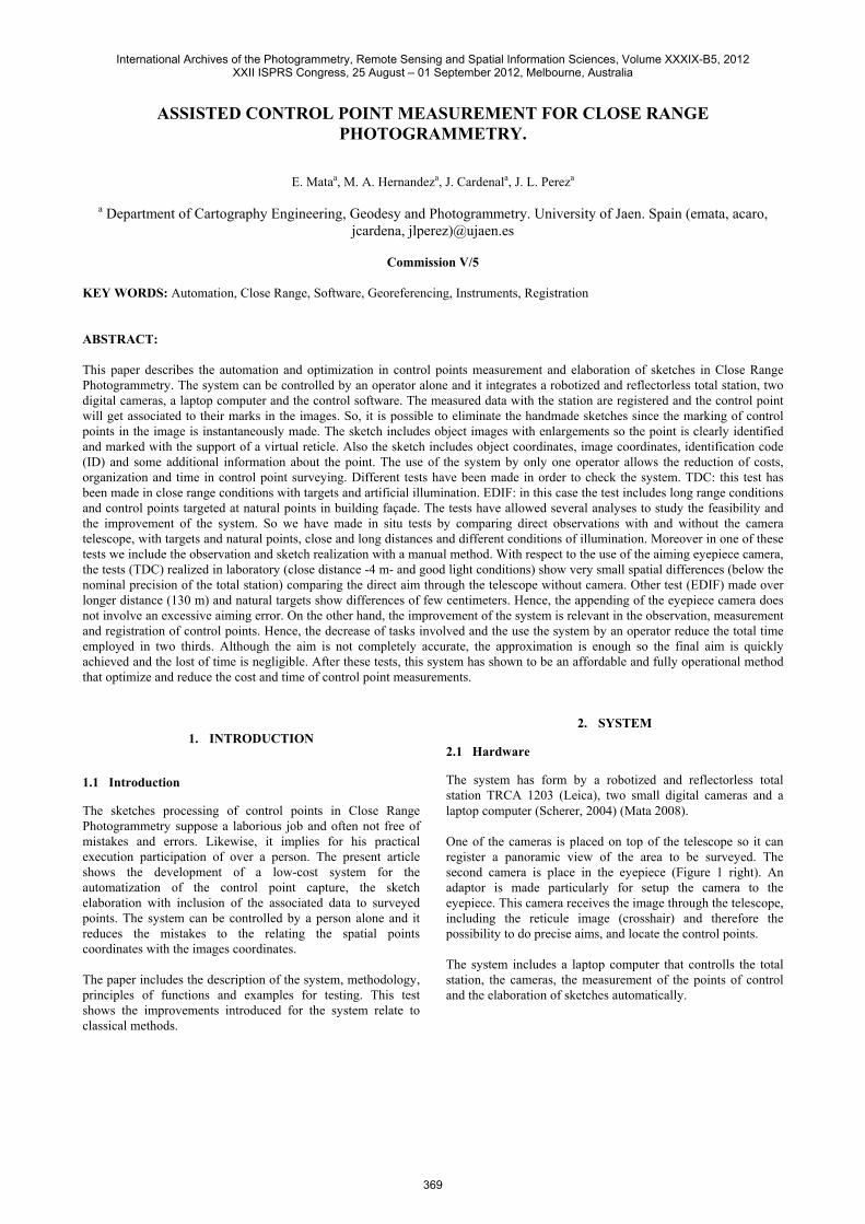
The system has form by a robotized and reflectorless total station TRCA 1203 (Leica), two small digital cameras and a laptop computer (Scherer, 2004) (Mata 2008). One of the cameras is placed on top of the telescope so it can register a panoramic view of the area to be surveyed. The second camera is place in the eyepiece (Figure 1 right). An adaptor is made particularly for setup the camera to the eyepiece. This camera receives the image through the telescope, including the reticule image (crosshair) and therefore the possibility to do precise aims, and locate the control points. The system includes a laptop computer that controlls the total station, the cameras, the measurement of the points of control and the elaboration of sketches automatically.
International Archives of the Photogrammetry, Remote Sensing and Spatial Information Sciences, Volume XXXIX-B5, 2012XXII ISPRS Congress, 25 August – 01 September 2012, Melbourne, Australia
369
The International Archives of the Photogrammetry, Remote Sensing and Spatial Information Sciences, Vol. 34, Part XXX
Figure 1. Sensor system. Right: total station and laptop. Left:
total station and coupled cameras. 2.2 Software
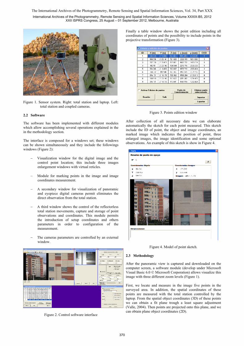
The software has been implemented with different modules which allow accomplishing several operations explained in the in the methodology section. The interface is composed for a windows set; these windows can be shown simultaneously and they include the followings windows (Figure 2):
Visualization window for the digital image and the control point location; this include three images enlargement windows with virtual reticles.
Module for marking points in the image and image
coordinates measurement.
A secondary window for visualization of panoramic and eyepiece digital cameras permit eliminates the direct observation from the total station.
A third window shows the control of the reflectorless total station movements, capture and storage of point observations and coordinates. This module permits the introduction of setup coordinates and others parameters in order to configuration of the measurement.
The cameras parameters are controlled by an external window.
Figure 2. Control software interface
Finally a table window shows the point edition including all coordinates of points and the possibility to include points in the projective transformation (Figure 3).
Figure 3. Points edition window After collection of all necessary data we can elaborate automatically the sketch for each point measured. This sketch include the ID of point, the object and image coordinates, an marked image which indicates the position of point, three enlarged images, the image identification and some optional observations. An example of this sketch is show in Figure 4.
Figure 4. Model of point sketch. 2.3 Methodology
After the panoramic view is captured and downloaded on the computer screen, a software module (develop under Microsoft Visual Basic 6.0 © Microsoft Corporation) allows visualize this image with three different zoom levels (Figure 1). First, we locate and measure in the image five points in the surveyed area. In addition, the spatial coordinates of these points are measured with the total station controlled by the laptop. From the spatial object coordinates (3D) of these points we can obtain a fit plane trough a least square adjustment (Valle, 2004). Then points are projected onto this plane, and we can obtain plane object coordinates (2D).
International Archives of the Photogrammetry, Remote Sensing and Spatial Information Sciences, Volume XXXIX-B5, 2012XXII ISPRS Congress, 25 August – 01 September 2012, Melbourne, Australia
370
The International Archives of the Photogrammetry, Remote Sensing and Spatial Information Sciences, Vol. 34, Part XXX
From both set of two dimensional coordinates –image and object plane coordinates- it is possible to make a 8-parameters two dimensional projective transformation with redundancy. Once the transformation parameters are known, it is possible to apply the inverse projective transformation Therefore, if we mark a point in the image by means of a device pointer (i.e. mouse cursor), automatically their object coordinates are known. This information is sent to the total station; thus the collimation axis of total station is directly pointed to the control point. The next step will be the measurement and the recording of the object coordinates of the point. The measured data with the station will be registered and it will get associated to the point marked on the image and its image coordinates. The precision in the automatic aim on a point depends of different factors; and each one of them constitutes a uncertainty source (Wolf, 2008). Therefore previous considerations about the errors must be mentioned. In relation to the coordinates image we can consider the resolution and the camera distortion. First, it is not necessary to calibrate the camera employed to capture the image, since it has to do with a previous image whose purpose is the data capture of control points; therefore a coarse final aim is sufficient. Also we must bear in mind the error committed by the operator marking the points on the image. The objects coordinates are influenced for different errors: set-up and orientation of total station, aims to the points, including the camera distortion if we employ this system and the total station angular and distance measurement precision. Finally, the transformation and the plane's fit introduce uncertainties in the final results. All these error sources do that final aim not be exact.
3. TESTS OF THE SYSTEM
Different tests have been made in order to check the system. The tests have allowed several analyses to study the feasibility and the improvement of the system. On the first experience we have compared aims with and without camera. The introduction of a new element in the measurement of spatial coordinates of control points can suppose an additional source of uncertainty. So we have made in situ tests by comparing direct observations with and without the camera telescope, in other words we made aims directly through the total station telescope and aims with the eyepiece camera. These tests have been made in different situations: with targets and natural points, close and long distances and different conditions of illumination. TDC - test; this test has been made in close range conditions with targets and artificial illumination, to simulate Industrial Photogrammetry working environments. Close distance -4 m- and good light conditions. Measures has been made firstly employing the eyepiece camera and next the same points has been measurement without this camera. Nine targets has been measured (Figure 5 left).
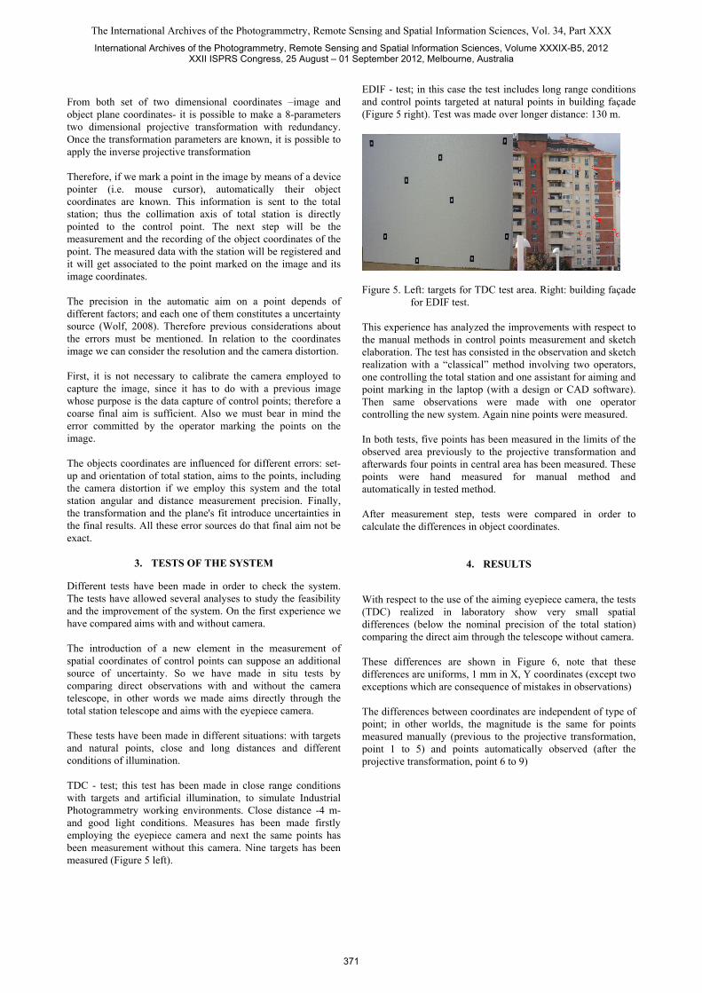
EDIF - test; in this case the test includes long range conditions and control points targeted at natural points in building façade (Figure 5 right). Test was made over longer distance: 130 m.
Figure 5. Left: targets for TDC test area. Right: building façade
for EDIF test. This experience has analyzed the improvements with respect to the manual methods in control points measurement and sketch elaboration. The test has consisted in the observation and sketch realization with a “classical” method involving two operators, one controlling the total station and one assistant for aiming and point marking in the laptop (with a design or CAD software). Then same observations were made with one operator controlling the new system. Again nine points were measured. In both tests, five points has been measured in the limits of the observed area previously to the projective transformation and afterwards four points in central area has been measured. These points were hand measured for manual method and automatically in tested method. After measurement step, tests were compared in order to calculate the differences in object coordinates.
4. RESULTS
With respect to the use of the aiming eyepiece camera, the tests (TDC) realized in laboratory show very small spatial differences (below the nominal precision of the total station) comparing the direct aim through the telescope without camera. These differences are shown in Figure 6, note that these differences are uniforms, 1 mm in X, Y coordinates (except two exceptions which are consequence of mistakes in observations) The differences between coordinates are independent of type of point; in other worlds, the magnitude is the same for points measured manually (previous to the projective transformation, point 1 to 5) and points automatically observed (after the projective transformation, point 6 to 9)
International Archives of the Photogrammetry, Remote Sensing and Spatial Information Sciences, Volume XXXIX-B5, 2012XXII ISPRS Congress, 25 August – 01 September 2012, Melbourne, Australia
371
The International Archives of the Photogrammetry, Remote Sensing and Spatial Information Sciences, Vol. 34, Part XXX
Diferences between object coordinates with camera and non - camera observations
-0.0015
-0.001
-0.0005
0
0.0005
0.001
0.0015
0.002
0.0025
1 2 3 4 5 6 7 8 9
Point
Met
ers Dif X.
Dif Y.
Dif Z.
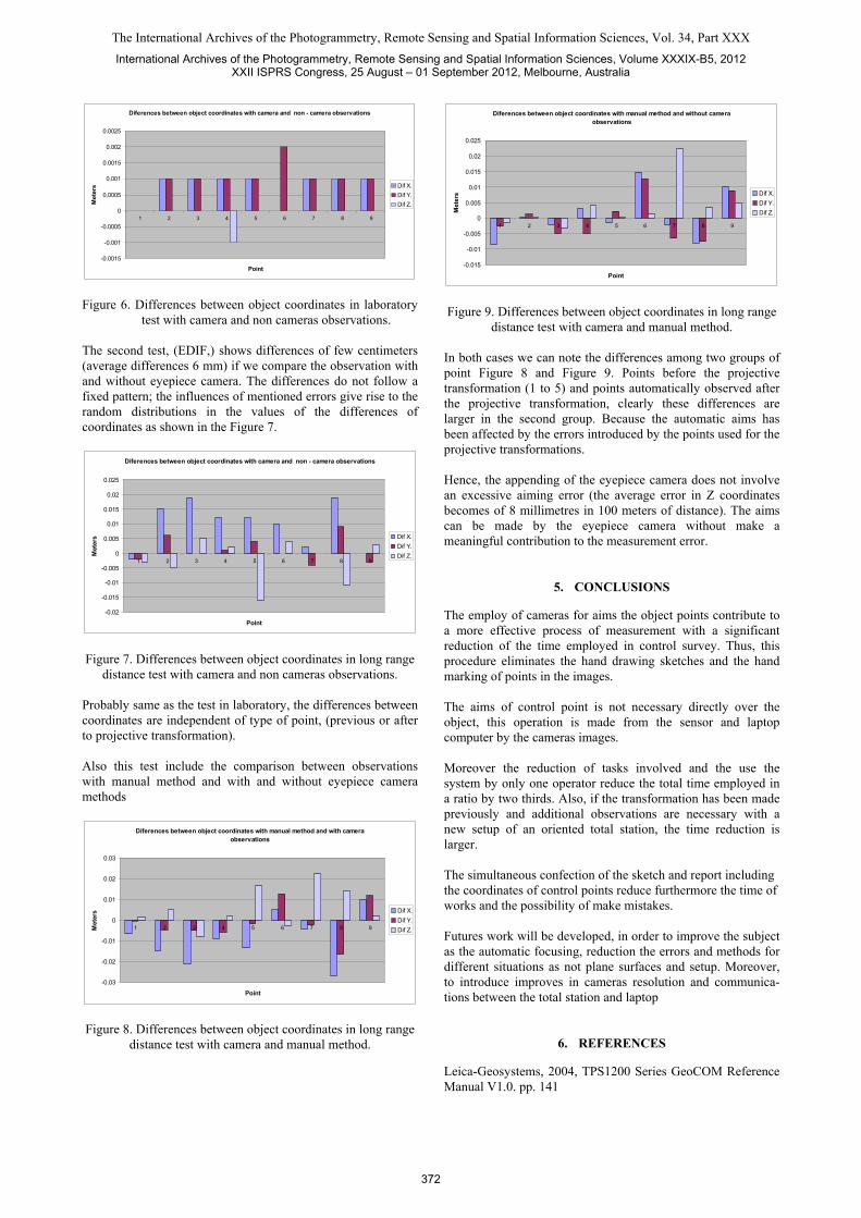
Figure 6. Differences between object coordinates in laboratory
test with camera and non cameras observations. The second test, (EDIF,) shows differences of few centimeters (average differences 6 mm) if we compare the observation with and without eyepiece camera. The differences do not follow a fixed pattern; the influences of mentioned errors give rise to the random distributions in the values of the differences of coordinates as shown in the Figure 7.
Diferences between object coordinates with camera and non - camera observations
-0.02
-0.015
-0.01
-0.005
0
0.005
0.01
0.015
0.02
0.025
1 2 3 4 5 6 7 8 9
Point
Met
ers Dif X.
Dif Y.
Dif Z.
Figure 7. Differences between object coordinates in long range
distance test with camera and non cameras observations. Probably same as the test in laboratory, the differences between coordinates are independent of type of point, (previous or after to projective transformation). Also this test include the comparison between observations with manual method and with and without eyepiece camera methods
Diferences between object coordinates with manual method and with camera observations
-0.03
-0.02
-0.01
0
0.01
0.02
0.03
1 2 3 4 5 6 7 8 9
Point
Met
ers Dif X.
Dif Y.
Dif Z.
Figure 8. Differences between object coordinates in long range distance test with camera and manual method.
Diferences between object coordinates with manual method and without camera observations
-0.015
-0.01
-0.005
0
0.005
0.01
0.015
0.02
0.025
1 2 3 4 5 6 7 8 9
Point
Met
ers Dif X.
Dif Y.
Dif Z.
Figure 9. Differences between object coordinates in long range
distance test with camera and manual method. In both cases we can note the differences among two groups of point Figure 8 and Figure 9. Points before the projective transformation (1 to 5) and points automatically observed after the projective transformation, clearly these differences are larger in the second group. Because the automatic aims has been affected by the errors introduced by the points used for the projective transformations. Hence, the appending of the eyepiece camera does not involve an excessive aiming error (the average error in Z coordinates becomes of 8 millimetres in 100 meters of distance). The aims can be made by the eyepiece camera without make a meaningful contribution to the measurement error.
5. CONCLUSIONS
The employ of cameras for aims the object points contribute to a more effective process of measurement with a significant reduction of the time employed in control survey. Thus, this procedure eliminates the hand drawing sketches and the hand marking of points in the images. The aims of control point is not necessary directly over the object, this operation is made from the sensor and laptop computer by the cameras images. Moreover the reduction of tasks involved and the use the system by only one operator reduce the total time employed in a ratio by two thirds. Also, if the transformation has been made previously and additional observations are necessary with a new setup of an oriented total station, the time reduction is larger. The simultaneous confection of the sketch and report including the coordinates of control points reduce furthermore the time of works and the possibility of make mistakes. Futures work will be developed, in order to improve the subject as the automatic focusing, reduction the errors and methods for different situations as not plane surfaces and setup. Moreover, to introduce improves in cameras resolution and communica-tions between the total station and laptop
6. REFERENCES
Leica-Geosystems, 2004, TPS1200 Series GeoCOM Reference Manual V1.0. pp. 141
International Archives of the Photogrammetry, Remote Sensing and Spatial Information Sciences, Volume XXXIX-B5, 2012XXII ISPRS Congress, 25 August – 01 September 2012, Melbourne, Australia
372
The International Archives of the Photogrammetry, Remote Sensing and Spatial Information Sciences, Vol. 34, Part XXX
Mata E, Hernandez M. A, Perez J. L. Cardenal J. 2008 Low Cost Automatized System for Control Points Capture in Close Range Photogrammetry. The International Archives of the Photogrammetry, Remote Sensing and Spatial Information Sciences, Beijing, China , Vol. XXVII, Part B5, p.p. 107 – 110
Scherer M., 2004. How to optimise the recording of geometrical data and image data for the purpose of architectural surveying. The International Archives of the Photogrammetry, Remote Sensing and Spatial Information Sciences, Istanbul, Turkey, Vol. XXV, Part B5, p.p. 228 – 232
Valle, J. M., Rodriguez, A., Lopetegui, A. 2004. Enfoque cartográfico de los Modelos Virtuales de elementos patrimoniales. VIII Congreso Nacional de Topografía y Cartografía TOPCART 2004, Madrid, Spain, 12 p.
Wolf, P. R. Ghilani, C. D. 2008. Elementary Surveying. An Introduction to Geomatic. 12th ed. Upper Saddle River, New Jersey, Pearson Prentice Hall.
ACKNOWLEDGEMENTS The present study has been financed by grant CGL2006-05906/BTE (MAPMUT) from the R+D+I Program of the Span-ish Ministerio de Educación y Ciencia, IFOTEL project TIN2009-09939 from the Ministry of Science and Innovation, National Programme R+D+I and European Regional Devel-opment Funds (ERDF-FEDER) and Sistemas Fotogrametricos y Topometricos Research Group (TEP-213; PAI-Junta de Anda-lucia). Also we acknowledge to Mr. Armando Morales of Leica-Geosystems (Spain) for answer all questions in relation to the total station functions.
International Archives of the Photogrammetry, Remote Sensing and Spatial Information Sciences, Volume XXXIX-B5, 2012XXII ISPRS Congress, 25 August – 01 September 2012, Melbourne, Australia
373