assembly manual manuel de montage - … · • phillips head screwdriver (not included) assembly...
TRANSCRIPT

Assembly ManualManuel de montage
Nautilus® Bowflex® Schwinn® Fitness Universal®
PR3000 Home Gym
8001491.120112.B
Français Canadien
English
® ®

Table of Contents
Before Assembly...................................................................... 2
Tools ........................................................................................... 2
Important Safety Instructions ................................................ 3
Hardware .................................................................................. 4
Parts ........................................................................................... 5
Assembly ................................................................................... 6
Assemble the Base .......................................................... 6 Attach the Rod Pack ........................................................ 7 Attach the Lower Lat Assembly ..................................... 8 Attach the Seat Support Rail .......................................... 9 Attach Pulley Arms ......................................................... 10 Attach the Seat Bottom to the Seat Backbone ......... 11
Attach Leg Extension Assembly ................................... 12 Attach Seat Back ............................................................ 13 Attach the Lat Crossbar with Pulleys ...........................................14 Attach the Rear Lat Cross Bar ...................................... 15 Attach the Upper Lat Tower Assembly ....................... 16 Attach the Lat Pulley Housing ...................................... 17 Cable and Pulley Routing .............................................. 18 Connect the Rod Cables ................................................ 19 Connect the Right Cable ................................................ 20 Leg Extension Cable Routing ........................................ 21 Final Inspection ............................................................... 21Gymnase à domicile PR3000 ............................................... 22
Contacts................................................................................... 44
Before AssemblySelect where you are going to locate your Bowflex® home gym carefully. The best location is on a hard, level surface. For best results, assemble your home gym in the location where you intend to use it. For safe operation, allow a workout area of at least 100” x 86” (2.6m x 2.2m) of free space.
Follow these basic tips when assembling your home gym.
1. Collect all the pieces needed for each assembly step.
2. Turn all the bolts and locknuts toward the right to tighten. Turn towards the left to loosen.
3. Use a combination wrench to grip the locknut when you tighten a bolt that has a locknut to make sure it is tight.
4. You may find the use of a utility knife or scissors beneficial during the unpacking and assembly process.
5. Carefully lift pieces when attaching. Look through the bolt holes to help guide bolt placement.
6. Assembly requires 2 people.
NOTICE: Leave all of the cables wrapped and bagged until the Bowflex® home gym is completely assembled.
Tools• (2)AdjustableWrenches(notincluded)• Phillips Head Screwdriver (not included)
Assembly Manual2

Important Safety Instructions
• Keepbystandersandchildrenawayfromtheproductyouareassemblingatalltimes.
• Donotassemblethismachineoutdoorsorinawetormoistlocation.
• Makesureassemblyisdoneinanappropriateworkspaceawayfromfoottrafficandexposuretobystanders.
• Somecomponentsofthemachinecanbeheavyorawkward.Useasecondperson whendoingtheassembly stepsinvolvingtheseparts.Donotdostepsthatinvolveheavyliftingorawkwardmovementsonyourown.
• Setupthismachineonasolid,level,horizontalsurface.
• Donottrytochangethedesignorfunctionalityofthismachine.Thiscouldcompromisethesafetyandcanvoid the warranty.
• If replacement parts are necessary use only genuine Nautilus® replacement parts and hardware. Failure to use genuine replacement parts can cause a risk to users, keep the machine from operating correctly or void the warranty.
• Donotuseorputthemachineintoserviceuntilthemachinehasbeenfullyassembledandinspectedforcorrect performance in accordance with the Owner’s Manual.
• ReadandunderstandthecompleteOwner’sManualsuppliedwiththismachinebeforefirstuse.Keepthe Owner’s and Assembly Manuals for future reference.
Thisiconmeansapotentiallyhazardoussituationwhich,ifnotavoided,couldresultindeathorseriousinjury.
Read and understand all warnings on this machine. Carefully read and understand the Assembly Manual.
Obey the following warnings:
Assembly Manual3

Hardware
(Hardwarenotactualsize)
Qty. 13 Item #13/8”x 3/4” Hex Head Bolt
Qty. 2 Item #111/2” x 9 1/2” Threaded Stud
Qty. 2 Item #25/16”x 2 1/2” Hex Head Bolt
Qty. 4Item #12Ball Stop
Qty. 5Item #31/4”Washer
Qty. 2Item #133/8” x 3” Hex Head Bolt
Qty. 4Item #41/2”Washer
Qty. 2 Item #141/2” x 5 1/4” Hex Head Bolt
Qty. 29Item #53/8”Washer
Qty. 4 Item #155/16” x 3/4” Hex Head Bolt
Qty. 3 Item #6#10 x 1” Phillips Head Screw
Qty. 4 Item #163/8” x 2 3/4” Hex Head Bolt
Qty. 8Item #73/8” Nylock Nut
Qty. 6Item #175/16”Washer
Qty. 4Item #81/2”WideWasher
Qty. 1Item #18Seat Pin
Qty. 6Item #91/2” Nylock Nut
Qty. 2 Item #191/4 x 1” Phillips Head Screw
Qty. 6Item #10Snap Hook
Qty. 2 Item #203/8” x 3 1/4” Hex Head Bolt
Assembly Manual4

Parts
21 1 Base Platform22 1 Right Frame Rail23 1 Left Frame Rail24 1 Rear Cross Bar25 1 Central Support26 1 Lat Cross Bar with Pulleys27 1 Rear Lat Cross Bar28 1 Upper Lat Tower29 1 Right Pulley Arm30 1 Left Pulley Arm31 1 Rod Pack32 1 Lower Lat Tower33 1 Seat Back34 1 Seat Backbone35 1 Seat Bottom36 1 Seat Support Rail37 2 Floating Pulleys38 1 Lat Pulley Housing
39 1 Leg Extension Assembly40 2 Roller Tubes41 4 Foam Roller Pads42 1 Placard43 1 Rod Pack Strap44 2 AdjustableHandgrips45 2 Handgrips46 1 Accessory Bag #147 2 Leg Press Extension Cables48 1 Snap Hook49 1 Accessory Bag #250 4 Roller End Caps51 1 Leg Extension Lock Pin52 1 Seat Backbone Lock Pin53 1 Hardware Bag54 1 ManualKit55 1 Rod Box End Plate
Item # Item #Qty. Qty.Description Description
21
22
23
24
25
26
2728
29
30
31
32
33
34
35 38
37
38
39
40
41
42
43 44 4546
47
48
49
50
51
52
5354
55
Assembly Manual5

Assembly
Step 1: Assemble the Base Parts• BasePlatform(#21)• RightFrameRail(#22)• LeftFrameRail(#23)• RearCrossBar(#24)• CentralSupport(#25)
Hardware• (4)3/8”x3/4”HexHeadBolts(#1)• (4)3/8”x23/4”HexHeadBolts(#16)• (12)3/8”Washers(#5)• (4)3/8”NylockNuts(#7)
Tools• (2)AdjustableWrenches(notincluded)
1-1 Put the Base Assembly parts on the floor.
1-2 Align the bolt holes on the Right and Left Frame Rails with the holes in the Base Platform, Rear Cross Bar and the Central Support.
1-3 Insert all the hardware, but do not tighten.
1-4Withallthehardwareinplace,tightenit.
22
23
24
21
5
16
25
1
7
Assembly Manual6

Assembly
Step 2: Attach the Rod PackParts• RodPack(#31)• LowerLatTower(#32)• RodPackStrap(#43)
Hardware• (3)#10x1”PhillipsHeadScrews(#6)• (5)1/4”Washers(#3)• (2)1/4x1”PhillipsHeadScrews(#19)
Tools• PhillipsHeadScrewDriver(notincluded)
2-1 Slide the Rod Pack into the Lower Lat Tower.
2-2 Install and tighten the hardware.
32
31
43
36
193
Assembly Manual7

Assembly
Step 3: Attach the Lower Lat Assembly to the Base AssemblyParts• CompetedAssembly(fromstep1)• LowerLatTowerAssembly(fromstep2)
Hardware• (4)3/8”Washers(#5)• (2)3/8”NylockNuts(#7)• (2)3/8”x31/4”HexHeadBolts(#20)
Tools• AdjustableWrench(notincluded)
3-1 Put the Lower Lat Tower Assembly onto the Completed Assembly.
3-2 Install and tighten the hardware.
57
20
Assembly Manual8

Assembly
Step 4: Attach the Seat Support RailParts• SeatSupportRail(#36)• CompletedAssembly(fromstep3)
Hardware• (4)3/8”x3/4”HexHeadBolts(#1)• (4)3/8”Washers(#5)
Tools• AdjustableWrench(notincluded)
4-1 Attach the Seat Support Rail to the Lower Lat Tower.
4-2 Install and tighten the hardware.
51
36
Assembly Manual9

Assembly
Step 5: Attach the Pulley ArmsParts• RightPulleyArm(#29)• LeftPulleyArm(#30)• CompletedAssembly(fromstep4)
Hardware• (2)1/2”x91/2”ThreadedStuds(#11)• (4)1/2”WideWashers(#8)• (4)1/2”NylockNuts(#9)
Tools• (2)AdjustableWrenches(notincluded)
5-1 Attach the the Right and Left Pulley Arms to the Completed Assembly.
5-2 Install and tighten the hardware.
9
8
9
11
8
29
30
Assembly Manual10

Assembly
Step 6: Attach the Seat Bottom to the Seat BackboneParts• SeatBottom(#35)• SeatBackbone(#34)
Hardware• (4)5/16”x3/4”HexHeadBolts(#15)• (4)5/16”Washers(#17)• (1)SeatPin(#18)
Tools• AdjustableWrench(notincluded)
6-1 Attach the Seat Bottom to the Seat Backbone.
6-2 Install and tighten the hardware.
6-3 Attach to Seat Support Rail.
35
34
17
15
18
Assembly Manual11

Assembly
Step 7: Attach the Leg Extension AssemblyParts• LegExtensionAssembly(#39)• RollerTubes(#40) • (4)FoamRollerPads(#41)• LegExtensionLockPin(#51)• SeatBottomAssembly(fromstep6)
Hardware• (1)SeatPin(#18)
7-1 Attach the Leg Extension Assembly to the Seat Bottom Assembly with the Leg Extension Lock Pin.
39
51
41
40
Assembly Manual12

Assembly
Step 8: Attach the Seat BackParts• SeatBack(#33)• CompletedAssembly(fromstep5)
Hardware• (2)5/16”x21/2”HexHeadBolts(#2)• (2)5/16”Washers(#17)
Tools• AdjustableWrench(notincluded)
8-1 Attach the Seat Back to the Seat Support Rail.
8-2 Install and tighten the hardware.
33 17
2
Assembly Manual13

Assembly
Step 9: Attach the Lat Crossbar with Pulleys to the Upper Lat TowerParts• LatCrossbarwithPulleys(#26)• UpperLatTower(#28)
Hardware• (2)3/8”x3”HexHeadBolts(#13)• (4)3/8”Washers(#5)• (2)3/8”NylockNuts(#7)
Tools• (2)AdjustableWrenches(notincluded)
9-1 Attach the Lat Crossbar with Pulleys to the Upper Lat Tower.
9-2 Install and tighten the hardware.
7
5
13
28
26
Assembly Manual14

Assembly
Step 10: Attach the Rear Lat Cross BarParts• RearLatCrossBar(#27)• UpperLatTowerAssembly(fromstep9)
Hardware• (2)1/2”x51/4”HexHeadBolts(#14)• (4)1/2”Washers(#4)• (2)1/2”NylockNuts(#9)
Tools
• (2)AdjustableWrenches(notincluded)
10-1 Attach the Rear Lat Cross Bar to the Upper Lat Tower Assembly.
27
14
4
9
Assembly Manual15

Assembly
Step 11: Attach the Upper Lat Tower AssemblyParts• CompletedAssembly(fromstep8)
Hardware• (2)3/8”x3/4”HexHeadBolts(#1)• (2)3/8”Washers(#5)
Tools• AdjustableWrench(notincluded)
11-1 Attach the Upper Lat Tower Assembly to the Base Assembly.
11-2 Install and tighten the hardware.
5
1
Assembly Manual16

Assembly
Step 12: Attach the Lat Pulley HousingParts• LatPulleyHousing(#38)• CompletedAssembly(fromstep11)
Hardware• (3)3/8”x3/4”HexHeadBolts(#1)• (3)3/8”Washers(#5)
Tools• AdjustableWrench(notincluded)
12-1 Attach the Lat Pulley Housing to the Lat Tower.
Note: Rod Pack removed from illustration for clarity.
1
1
38
5
Assembly Manual17

Assembly
Step 13: Cable and Pulley Routing the Rear PulleysParts• CompletedAssembly(fromstep12)Tools• AdjustableWrench(notincluded)
13-1Removethe3/8”x41/2”HexHeadBoltandthe3/8”WasherinthecenteroftheLatPulleyHousing.
13-2 Remove the two pulley wheels from the Lat Pulley Housing.
13-3 Unwrap the Right Pulley Cable from the Right Frame Rail and thread it under and then over one of the pulley wheels. Pinch the Right Pulley Cable to the pulley wheel until installed.
13-4 Unwrap the Left Pulley Cable on the Left Frame Rail and thread it under and then over the other pulley wheel.
13-5 Put the pulleys with the cables wrapped around them back into the Lat Pulley Housing.
13-6Replaceandtightenthe3/8”x41/2”HexHeadBoltandthe3/8”WasherinthecenteroftheLatPulleyHousing.
Assembly Manual18
Assembly
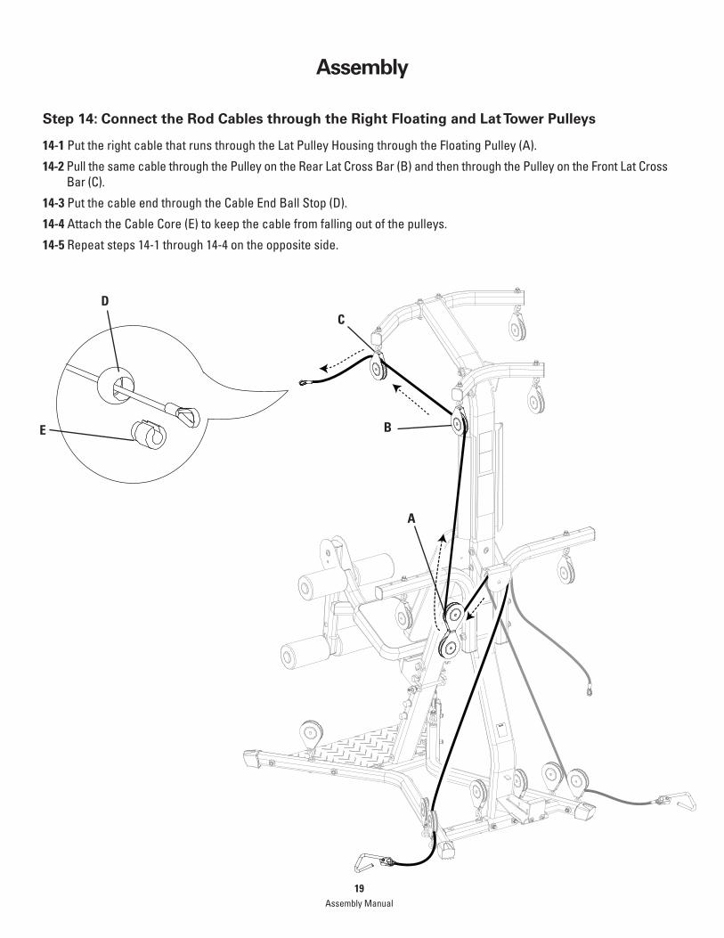
Step 14: Connect the Rod Cables through the Right Floating and Lat Tower Pulleys
14-1 Put the right cable that runs through the Lat Pulley Housing through the Floating Pulley (A).
14-2 Pull the same cable through the Pulley on the Rear Lat Cross Bar (B) and then through the Pulley on the Front Lat Cross Bar (C).
14-3PutthecableendthroughtheCableEndBallStop(D).
14-4 Attach the Cable Core (E) to keep the cable from falling out of the pulleys.
14-5 Repeat steps 14-1 through 14-4 on the opposite side.
A
C
B
D
E
Assembly Manual19

Assembly
Step 15: Connect the Right Squat Cable through the Floating and Main Assembly Pulleys
15-1 Unwrap the Right Squat Cable from the Pulley on the front of the Base.
15-2 Put the cable under the cable shroud and under and through the Rear Cross Bar Pulley. Follow the arrows.
15-3 Put the cable down through the Inner Right Frame Rail Pulley and up through the Right Pulley Arm Pulley.
15-4 Put the cable end through the Cable End Ball Stop (A).
15-5 Attach the Cable Core (B) to keep the cable from falling out of the pulleys.
15-6 Repeat steps 15-1 through 15-5 on the opposite side.
A
B
Assembly Manual20

47
48
48
Assembly
Step A: Leg Press Extension Cable RoutingParts•(3)SnapHooks(#48)•(2)LegPressExtensionCables(#47)
A-1 Attach one set of snap hooks onto the left and right squat cables.
A-2 Attach the Leg Press Extension Cables.
A-3 Attach a snap hook to the Leg Extension Assembly and connect the Leg Press Extension Cables.
Final InspectionInspect your machine to ensure that all fasteners are tight and components are properly assembled.
Failure to visually check and test assembly before use can cause damage to the equipment. It can also cause seriousinjurytousersandbystanders.
Assembly Manual21

Manuel de montage
Nautilus® Bowflex® Schwinn® Fitness Universal®
Gymnase à domicile PR3000
Français Canadien
® ®

Table des matières
Avant le montage ...................................................... 23
Outils ........................................................................... 23
Précautions de sécurité importantes ................... 24
Quincaillerie.............................................................. 25
Pièces ......................................................................... 26
Montage ..................................................................... 27
Assemblage de la base .................................... 27 Fixation des tiges ............................................... 28 Fixation de l’assemblage latéralinférieur ...... 29 Fixation de la glissière du support du siège .. 30 Fixation des bras de poulie .............................. 31
Fixation de la base du siège au dos du siège .................. 32Fixationdel’extensiondesjambes ................................. 33Fixation du dos du siège .................................................... 34Fixation de la barre transversale latérale avec poulies . 35Fixation de la barre transversale latérale arrière ......... 36Fixation de la tour latérale supérieure ............................ 37Fixation de l’enveloppe des poulies latérales ............... 38Acheminement des câbles et des poulies ..................... 39Branchement des câbles de la tige ................................ 40Branchement du câble droit ............................................. 41Acheminementducâbledel’extensiondesjambes .... 42Inspection finale ................................................................. 42
Coordonnées.............................................................................. 44
Avant le montage
Sélectionnezavecsoinl’endroitoùvousallezplacervotregymnaseàdomicileBowflex®.Lemeilleuremplacementestsurunesurfacedureetplane.Pourunrésultatoptimal,montezvotregymnaseàdomicileàl’endroitoùvousavezl’intentiondel’utiliser.Pouruneutilisationsansdanger,ménagezunespaced’entraînementd’aumoins2,6mx2,2m(100 po x 86 po) d’espace libre.
Respectezcesconseilsdebasepourquevotremontagesoitrapideetfacile.
1. Rassembleztouteslespiècesnécessairespourchaqueétape.
2.Tourneztouslesécrousetlesécrousautobloquantversladroitepourlesserrer.Tournez-lesverslagauchepourles desserrer.
3. Lorsquevousserrezunécrouautobloquantsurunboulon,utilisezuneclémixteetassurez-vousqu’ilestcorrectement serré.
4. Un couteau ou une paire de ciseaux pourront vous être utiles pour le déballage et le montage.
5.Lorsquevousattachezdeuxpièces,soulevezdoucementetregardezparlestrousdeboulonsafindevousaideràguider le boulon dans le trou.
6. Le montage requiert deux personnes.
REMARQUE:LaisseztouslescâblesenveloppésetliéstantquevotregymnaseàdomicileBowflex®n’estpascomplètement monté.
Outils• (2)Clésajustables(nonincluses)
• TournevisàtêtePhillips(nonincluses)
Manuel de montage23

Précautions de sécurité importantes
• Teneztoujourslespassantsetlesenfantsàl’écartduproduitquevousmontez.
• Nemontezpasl’appareildansunlieuhumide.
• Assurez-vousquelemontageesteffectuédansunespacedetravailapproprié,àl’écartdelacirculationetdel’exposition aux passants.
• Certainscomposantsdelamachinepeuventêtrelourdsouencombrants.Faitesappelàunedeuxièmepersonnepourprocéderauxétapesdemontagequiconcernentcespièces.Neréalisezpasseulelesétapesdemontagenécessitantlelevaged’objetslourdsoudesmouvementsdifficiles.
• Installezcettemachinesurunesurfaceplaneethorizontalesolide.
• Netentezpasdechangerlaconceptionoulafonctionnalitédecettemachine.Celapourraitcompromettrelasécurité et rendre caduque la garantie.
• Sidespiècesderechangesontnécessaires,utilisezexclusivementdespiècesderechangeetlaquincaillerieNautilus® d’origine. Le fait de ne pas utiliser de pièces de rechange authentiques pourrait provoquer un risque pour les utilisateurs, empêcher la machine de fonctionner correctement ou rendre caduque la garantie.
• N’utilisezpaslamachineetnelamettezpasenmarchetantqu’ellen’estpascomplètementmontéeetinspectée pour vérifier que ses performances correspondent aux stipulations du Guide du propriétaire.
• LisezetassimilezdansonintégralitéleGuidedupropriétairefournitaveccettemachineavantlapremièreutilisation.ConservezleGuidedupropriétairepourréférencefuture.
Cetteicôneindiqueunesituationpotentiellementdangereuse,laquelle,siellen’estpasévitée,peutentraînerla mort ou des blessures graves.
Lisezetassimileztouslesavertissementsapposéssurcettemachine.LisezattentivementetcomprenezleManueldemontage.
Avant d’utiliser cet équipement, veuillez vous conformer aux avertissements suivants :
Manuel de montage24

Qté. 13 Pièce no 1Boulonàtêtehexagonale 3/8 po x 3/4 po
Qté 2 Pièce no 11Goujonfileté1/2pox9 1/2 po
Qté 2 Pièce no 2Boulonàtêtehexagonale 5/16 po x 2 1/2 po
Qté 4 Pièce no 12Bague d’arrêt
Qté. 5Pièce no 3Rondelle 1/4 po
Qté 2 Pièce no 13Boulonàtêtehexagonale 3/8 po x 3 po
Qté. 4Pièce no 4Rondelle 1/2 po
Qté. 2 Pièce no 14Boulonàtêtehexagonale 1/2 po x 5 1/4 po
Qté 29Pièce no 5Rondelle 3/8 po
Qté 4 Pièce no 15Boulonàtêtehexagonale 5/16 po x 3/4 po
Qté 3Pièce no 6VisàtêtePhillipsno10x 1 po
Qté. 4 Pièce no 16Boulonàtêtehexagonale 3/8 po x 2 3/4 po
Qté 8 Pièce no 7Écrouàfreinélastique3/8 po
Qté 6Pièce no 17Rondelle 5/16 po
Qté 4 Pièce no 8Rondelle 1/2 po de large
Qté 1Pièce no 18Goupille du siège
Qté 6 Pièce no 9Écrouàfreinélastique1/2 po
Qté. 2 Pièce no19VisàtêtePhillips1/4 po x 1 po
Qté 6Pièce no 10Mousqueton
Qté. 2 Pièce no 20Boulonàtêtehexagonale 3/8 po x 3 1/4 po
Quincaillerie
(Laquincaillerien’estpasàlatailleréelle)
Manuel de montage25

Pièces
Pièce # Pièce #Qté. Qté.Description Description
21 1 Plate-forme de la base22 1 Longeron droit23 1 Longeron gauche24 1 Barre transversale arrière25 1 Support central26 1 Barre transversale latérale avec poulies 27 1 Barre transversale latérale arrière28 1 Tour latérale supérieure29 1 Bras de poulie droit30 1 Bras de poulie gauche31 1 Ensemble de tiges32 1 Tour latérale inférieure33 1 Dossierdusiège34 1 Dossierdusiège35 1 Base du siège36 1 Glissière du support du siège37 2 Poulies flottantes38 1 Enveloppe de la poulie latérale
39 1 Assemblagedel’extensiondesjambes40 2 Cylindres41 4 Rouleaux de mousse42 1 Panneau d’affichage43 1 Sangle de l’ensemble de tiges44 2 Poignéesajustables45 2 Poignées46 1 Sac d’accessoires no147 2 Câblesd’extensiondudéveloppédesjambes48 1 Mousqueton49 1 Sac d’accessoires no250 4 Capuchons de cylindre51 1 Goupilledeverrouillagedel’extensiondesjambes52 1 Goupille de verrouillage du dos du siège53 1 Sac de quincaillerie54 1 Kitdumanuel55 1 Plaqued’extrémitéduboîtierdelatige
21
22
23
24
25
26
2728
29
30
31
32
33
34
35 38
37
38
39
40
41
42
43 44 4546
47
48
49
50
51
52
5354
55
Manuel de montage26
Montage
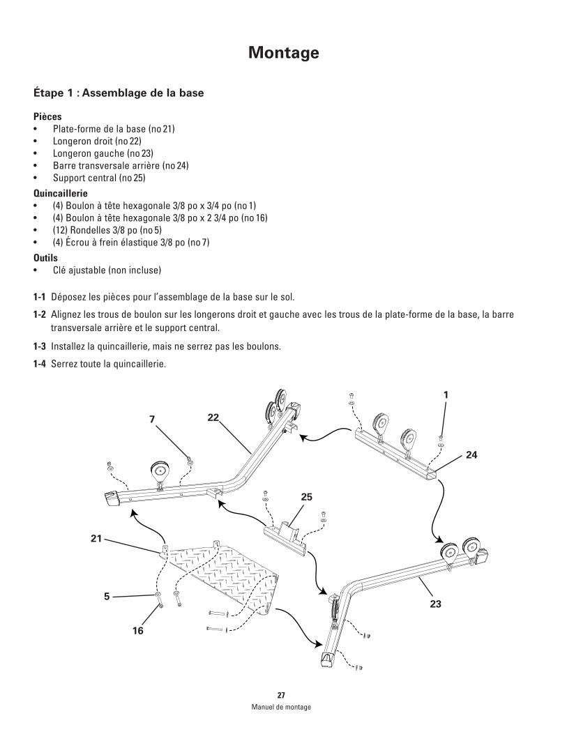
Étape 1 : Assemblage de la base
Pièces• Plate-formedelabase(no 21)• Longerondroit(no 22)• Longerongauche(no 23)• Barretransversalearrière(no 24)• Supportcentral(no 25)Quincaillerie• (4)Boulonàtêtehexagonale3/8pox3/4po(no 1)• (4)Boulonàtêtehexagonale3/8pox23/4po(no 16)• (12)Rondelles3/8po(no 5)• (4)Écrouàfreinélastique3/8po(no 7)Outils• Cléajustable(nonincluse)
1-1 Déposezlespiècespourl’assemblagedelabasesurlesol.
1-2 Alignezlestrousdeboulonsurleslongeronsdroitetgaucheaveclestrousdelaplate-formedelabase,labarretransversale arrière et le support central.
1-3 Installezlaquincaillerie,maisneserrezpaslesboulons.
1-4 Serreztoutelaquincaillerie.
22
23
24
21
5
16
25
1
7
Manuel de montage27

Montage
Étape 2 : Fixation des tiges
Pièces• Ensembledetiges(no31)• Tourlatéraleinférieure(no32)• Sanglepourl’ensembledetiges(no43)Quincaillerie• (3)VisàtêtePhillipsno10x1po(no6)• (5)Rondelles1/4po(no3)• (2)VisàtêtePhillips1/4 po x 1 po ( no19)Outils• TournevisàtêtePhillips(noninclus)
2-1 Faites glisser l’ensemble de tiges dans la tour latérale inférieure.
2-2 Installezetserrezlaquincaillerie.
32
31
43
36
193
Manuel de montage28

7
20
Manuel de montage29
Montage
Étape 3 : Fixation de l’assemblage de la tour latérale inférieure sur l’assemblage de la base
Pièces• Assemblageterminé(del’étape1)• Assemblagedelatourlatéraleinférieure(del’étape2)Quincaillerie• (2)Boulonàtêtehexagonale3/8pox3/4po(no 1)• (2)Rondelles3/8po(no 5)Outils• Cléajustable(nonincluse)
3-1 Déposezl’assemblagedelatourlatéraleinférieursurl’assemblageterminé.
3-2 Installezetserrezlaquincaillerie.

51
36
Manuel de montage30
Montage
Étape 4 : Fixation de la glissière du support du siège
Pièces• Glissièredusupportdusiège(no36)• Assemblageterminé(del’étape3)Quincaillerie• (4)Boulonàtêtehexagonale3/8pox3/4po(no1)• (4)Rondelles3/8po(no 5)Outils• Cléajustable(nonincluse)
4-1 Fixezlaglissièredusupportdusiègesurlatourlatéraleinférieure.
4-2 Installezetserrezlaquincaillerie.

9
8
9
11
8
29
30
Manuel de montage31
Montage
Étape 5 : Fixation des bras de poulie
Pièces• Brasdepouliedroit(no 29)• Brasdepouliegauche(no 30)• Assemblageterminé(del’étape4)Quincaillerie• (4)Boulonàtêtehexagonale3/8pox3/4po(no 1)• (4)Rondelles3/8po(no 5)• (2)Goujonsfiletés1/2pox91/2po(no 11)• (4)Rondelles1/2podelarge(no 8)• (4)Écrouàfreinélastique1/2po(no 9)Outils• (2)Clésajustables(nonincluses)
5-1 Fixezlesbrasdepouliedroitetgauchesurl’assemblageterminé.
5-2 Installezetserrezlaquincaillerie.

35
34
17
15
18
Manuel de montage32
Montage
Étape 6 : Fixation de la base du siège au dos du siège
Pièces• Basedusiège(no 35)• Dosdusiège(no 34)Quincaillerie• (4)Boulonsàtêtehexagonale5/16pox3/4po(no 15)• (4)Rondelles5/16po(no 17)Outils• Cléajustable(nonincluse)• (1)Goupille du siège (no 18)
6-1 Fixezlabasedusiègesurledosdusiège.
6-2 Installezetserrezlaquincaillerie.
6-3 Fixez sur la glissière du support du siège.

39
51
41
40
Manuel de montage33
Montage
Étape 7 : Fixation de l’extension des jambes
Pièces• Assemblagedel’extensiondesjambes(no 39)• Cylindres(no40)• (4)Rouleauxdemousse(no41)• Goupilledeverrouillagedel’extensiondesjambes(no 51)• Assemblagedelabasedusiège(del’étape6)
7-1 Fixezl’assemblagedel’extensiondesjambesàl’assemblagedelabasedusiègeaveclagoupilledeverrouillagedel’extensiondesjambes.

33 17
2
Manuel de montage34
Montage
Étape 8 : Fixation du dos du siège
Pièces• Dosdusiège(no 33)• Assemblageterminé(del’étape5)Quincaillerie• (2)Boulonàtêtehexagonale5/16pox21/2po(no 2)• (2)Rondelles5/16po(no 17)Outils• Cléajustable(nonincluse)
8-1 Fixezledosdusiègesurlaglissièredusupportdusiège.
8-2Installezetserrezlaquincaillerie.

7
5
13
28
26
Manuel de montage35
Montage
Étape 9 : Fixation de la barre transversale latérale avec les poulies sur la tour latérale supérieure
Pièces• Barretransversalelatéraleavecpoulies(no 26)• Tourlatéralesupérieure(no 28)Quincaillerie• (2)Boulonsàtêtehexagonale3/8pox3po(no 13)• (4)Rondelles3/8po(no 5)• (2)Écrousàfreinélastique3/8po(no 7)Outils• (2)Clésajustables(nonincluses)
9-1Fixezlabarretransversalelatéraleaveclespouliessurlatourlatéralesupérieure.
9-2 Installezetserrezlaquincaillerie.

27
14
4
9
Manuel de montage36
Montage
Étape 10 : Fixation de la barre transversale latérale arrière
Pièces• Barretransversalearrière(no 27)• Assemblagedelatourlatéralesupérieure(del’étape9)Quincaillerie• (2)Boulonàtêtehexagonale1/2pox51/4po(no 14)• (4)Rondelles1/2po(no 4)• (2)Écrousàfreinélastique1/2po(no 9)Outils• (2)Clésajustables(nonincluses)
10-1Fixezlabarretransversalelatéralearrièresurl’assemblagedelatourlatéralesupérieure.

5
1
Manuel de montage37
Montage
Étape 11 : Fixation de l’assemblage de la tour latérale supérieure sur l’assemblage de la base
Pièces• Assemblageterminé(del’étape8)Quincaillerie• (2)Boulonàtêtehexagonale3/8pox3/4po(no 1)• (2)Rondelles3/8po(no 5)Outils• Cléajustable(nonincluse)
11-1Fixezl’assemblagedelatourlatéralesupérieuresurl’assemblagedelabase.
11-2 Installezetserrezlaquincaillerie.

1
1
38
5
Manuel de montage38
Montage
Étape 12 : Fixation de l’enveloppe des poulies latérales
Pièces• Enveloppedespoulieslatérales(no 38)• Assemblageterminé(del’étape11)Quincaillerie• (3)Boulonàtêtehexagonale3/8pox3/4po(no 1)• (3)Rondelles3/8po(no 5)Outils• Cléajustable(nonincluse)
12-1Fixezl’enveloppedespoulieslatéralessurlatourlatérale.
Remarque : Ensemble de tiges retiré de l’illustration pour plus de clarté.

Manuel de montage39
Montage
Étape 13 : Acheminement des câbles dans les poulies et les poulies arrière
Pièces• Assemblageterminé(del’étape12)Outils• Cléajustable(nonincluse)
13-1Retirezleboulonàtêtehexagonal3/8pox41/2poetlarondelle3/8podanslecentredel’enveloppedelapoulielatérale.
13-2 Retirezlesdeuxrouesdepouliedel’enveloppedelapoulielatérale.
13-3Déballezlecâbledepouliedroitdulongerondroitetfaites-lepassersousetensuitepar-dessusunedesrouesde poulie.Coincezlecâbledepouliedroitsurlarouedelapouliejusqu’àcequ’ellesoitinstallée.
13-4Déballezlecâbledepouliegauchesurlelongerongaucheetfaites-lepassersousetensuitepar-dessusunedesroues de poulie.
13-5Remettezlessurlesquelleslescâblessontenroulésdansl’enveloppedepoulielatérale.
13-6Remettezleboulonàtêtehexagonal3/8pox41/2poetlarondelle3/8podanslecentredel’enveloppedelapoulielatéraleetserrez-le.

A
C
B
D
E
Manuel de montage40
Montage
Étape 14 : Branchement des câbles de tige dans les poulies flottante droite et de la tour latérale
14-1 Faites passer le câble droit qui passe dans l’enveloppe de la poulie latérale dans la poulie flottante (A).
14-2 Faites passer le même câble dans la poulie de la barre transversale latérale arrière (B) et ensuite dans la poulie de la barre transversale avant (C).
14-3 Faitespasserleboutducâbledanslal’emboutdelabagued’arrêt(D).
14-4 Attachezl’âmeducâble(E)afind’éviterquelecâblenesortedespoulies.
14-5 Refaiteslesétapes14-1à14-4del’autrecôté.

A
B
Manuel de montage41
Montage
Étape 15 : Branchement du câble de flexion des jambes droit dans les poulies flottantes et de l’assemblage principal
15-1Déballezlecâbledeflexiondejambesdroitdelapoulieàl’avantdelabase.
15-2Faitespasserlecâblesousl’enveloppedecâbleetsousetdanslapouliedelabarretransversalearrière.Suivezlesflèches.
15-3 Faites passer le câble vers le bas au travers de la poulie du longeron droit et vers le haut dans la poulie du bras de poulie droit.
15-4 Faites passer le bout du câble dans la l’embout de la bague d’arrêt (A).
15-5Attachezl’âmeducâble(B)afind’éviterquelecâblenesortedespoulies.
15-6Refaiteslesétapes15-1à15-5del’autrecôté.

47
48
48
Manuel de montage42
Montage
Étape A : Acheminement du câble d’extension du développé des jambes
Pièces•(3)Mousquetons(no 48)•(2)Câblesd’extensiondudéveloppédesjambes(no 47)
A-1Fixezunjeudemousquetonssurlescâblesdeflexiondesjambesdroitetgauche.
A-2Fixezlescâblesd’extensiondeflexiondesjambes.
A-3Fixezunmousquetonsurl’assemblagedel’extensiondesjambesetbranchezlescâblesd’extensiondeflexiondesjambes.
Inspection finaleInspectezvotremachine,pourvousassurerquetouteslescourroiessontserréesetquetouslescomposantssontcorrectement montés. Ne pas inspecter visuellement ni faire un essai du montage avant utilisation peut endommager l’équipement.
Cela peut aussi occasionner de sérieuses blessures aux utilisateurs et aux spectateurs.

Manuel de montage43

Nautilus,Inc.,(800)NAUTILUS/(800)628-8458,www.NautilusInc.com–Serviceàlaclientèle:AmériqueduNord(800)605-3369,[email protected]|Asie-PacifiqueetAmériquelatine360859-5180,[email protected]|ImpriméenChine|©2008Nautilusinc.Nautilus,Inc.,(800)NAUTILUS/(800)628-8458,www.NautilusInc.com–Serviceàlaclientèle:AmériqueduNord(800)605-3369,[email protected]|Asie-PacifiqueetAmériquelatine360859-5180,[email protected]|ImpriméenChine|©2008Nautilusinc.
FRC
EN
Nautilus® Bowflex® Schwinn® Fitness Universal®