assembly assembly (automatic 545rfe) electrical ... · 2c/4c clutch components should ... the 2c...
TRANSCRIPT

8/24/2015 DirectHit Search
http://www.identifix.com/SearchFixes/Index?ROID=114739013&VID=2188622&VSM=1&LocationId=2#KW=transmission&SOption=1&VETId=8&STMode=1… 1/11
ASSEMBLY (AUTOMATIC 545RFE)...
ASSEMBLY
NOTE: Apply trans jell or petroleum jelly to all slide portions, rolling contacts surfaces, thrust surfacesetc. to prevent burnout during initial operation. Lubricate Orings and Oring seals withMOPAR® ATF+4. Soak all friction disks in MOPAR® ATF+4 for at least two hours beforeassembly of clutch packs.
NOTE: Clean and inspect all components. Replace any components which show evidence of excessivewear or scoring.
NOTE: If the transmission assembly is being reconditioned (clutch/seal replacement) or replaced, it isnecessary to perform the Quick Learn Procedure using the scan tool. (Refer to 08 Electrical/Electronic Control Modules/MODULE, Transmission Control Standard Procedure)
1. Install a new selector shaft seal (1) using Seal Installer 8253 (2).

8/24/2015 DirectHit Search
http://www.identifix.com/SearchFixes/Index?ROID=114739013&VID=2188622&VSM=1&LocationId=2#KW=transmission&SOption=1&VETId=8&STMode=1… 2/11
2. Install the manual selector shaft and retaining screw. Tighten themanual selector shaft retaining screw to 28 N·m (250 in.lbs.).
3. Install the manual shift lever (1) onto the manual selector shaft.Tighten the retaining crossbolt to 16 N·m (140 in.lbs.).
4. Install the park pawl (5), spring (4), and shaft (3).
5. Install the park rod (7) and eclip.
6. Install the park rod guide (1) and snapring (2).
7. Install a new fill tube seal (2) using Seal Installer 8254 (1).

8/24/2015 DirectHit Search
http://www.identifix.com/SearchFixes/Index?ROID=114739013&VID=2188622&VSM=1&LocationId=2#KW=transmission&SOption=1&VETId=8&STMode=1… 3/11
NOTE: Before final assembly of transmission centerline, the2C/4C clutch components should be installed intoposition and measured as follows:
8. Install the 2C reaction plate (4) with the beveled edge down(rearward) into the transmission case.
9. Install the 2C clutch pack (2, 3) into the transmission case.
10. Install the flat 2C clutch snapring (1) into the transmission case.
11. Install the 4C retainer/bulkhead (2) into the transmission case.Make sure that the oil feed holes are pointing toward the valvebody area.
12. Install the 4C retainer/bulkhead tapered snapring (1) into thetransmission case. Make sure that the open ends of the snapringare located in the case opening toward the valve body area.
13. Using a feeler gauge through the opening in the rear of thetransmission case, measure the 2C clutch pack clearance betweenthe 2C reaction plate and the transmission case at four differentpoints. The average of these measurements is the 2C clutch packclearance. The correct clutch clearance is 0.4551.335 mm(0.0180.053 in.). The reaction plate is not selective. If the clutchpack clearance is not within specification, the reaction plate, all thefriction discs, and steels must be replaced.
14. Remove the 4C retainer/bulkhead and all of the 2C clutchcomponents from the transmission case.
15. Install the low/reverse clutch assembly (1). Make sure that the oilfeed hole points toward the valve body area and that the bleedorifice is aligned with the notch in the rear of the transmissioncase.
16. Install the snapring (2) to hold the low/reverse clutch retainer intothe transmission case. The snapring is tapered and must beinstalled with the tapered side forward. Once installed, verify thatthe snapring is fully seated in the snapring groove.
8/24/2015 DirectHit Search
http://www.identifix.com/SearchFixes/Index?ROID=114739013&VID=2188622&VSM=1&LocationId=2#KW=transmission&SOption=1&VETId=8&STMode=1… 4/11
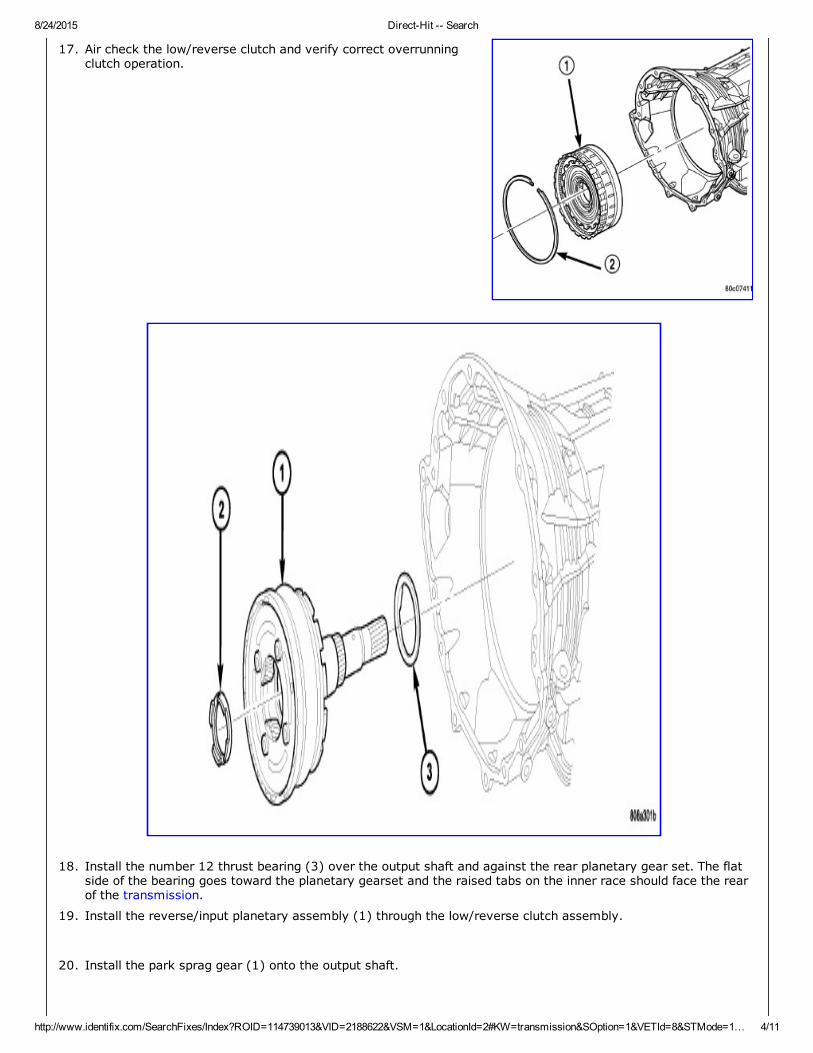
17. Air check the low/reverse clutch and verify correct overrunningclutch operation.
18. Install the number 12 thrust bearing (3) over the output shaft and against the rear planetary gear set. The flatside of the bearing goes toward the planetary gearset and the raised tabs on the inner race should face the rearof the transmission.
19. Install the reverse/input planetary assembly (1) through the low/reverse clutch assembly.
20. Install the park sprag gear (1) onto the output shaft.

8/24/2015 DirectHit Search
http://www.identifix.com/SearchFixes/Index?ROID=114739013&VID=2188622&VSM=1&LocationId=2#KW=transmission&SOption=1&VETId=8&STMode=1… 5/11
21. Install the snapring (1) to hold the park sprag onto the outputshaft.
22. Install the 2C reaction plate (4) with the beveled edge down(rearward) into the transmission case.
23. Install the 2C clutch pack (2, 3, 4) into the transmission case.

8/24/2015 DirectHit Search
http://www.identifix.com/SearchFixes/Index?ROID=114739013&VID=2188622&VSM=1&LocationId=2#KW=transmission&SOption=1&VETId=8&STMode=1… 6/11
INSTALL REACTION ANNULUS AND CARRIER
1 THRUST BEARING NUMBER 8 5 THRUST BEARING NUMBER 7
2 THRUST BEARING NUMBER 9 6 THRUST PLATE (SELECT)
3 REACTION PLANETARY CARRIER 7 THRUST BEARING NUMBER 6
4 REACTION SUN GEAR 8 REACTION ANNULUS
24. Install the number 8 thrust bearing (1) inside the reaction carrier with the outer race against the reactionplanetary carrier (3).
25. Install the reaction planetary gear set and the number 9 thrust bearing (2), with the inner race against thereaction planetary carrier (3), into the transmission case.
26. Install the flat 2C clutch snapring into the transmission case.
27. Install the reaction sun gear (4) into the reaction planetary gear set. Make sure the small shoulder is facingthe front of the transmission.
28. Install the number 7 thrust bearing (5) onto the reaction sun gear (4) with the inner race against the sun gear.
29. Install the output shaft selective thrust plate (2) onto the reactionannulus with the oil grooves facing the annulus gear and the lugs(1) and notches aligned as shown.

8/24/2015 DirectHit Search
http://www.identifix.com/SearchFixes/Index?ROID=114739013&VID=2188622&VSM=1&LocationId=2#KW=transmission&SOption=1&VETId=8&STMode=1… 7/11
INSTALL REACTION ANNULUS AND CARRIER
1 THRUST BEARING NUMBER 8 5 THRUST BEARING NUMBER 7
2 THRUST BEARING NUMBER 9 6 THRUST PLATE (SELECT)
3 REACTION PLANETARY CARRIER 7 THRUST BEARING NUMBER 6
4 REACTION SUN GEAR 8 REACTION ANNULUS

8/24/2015 DirectHit Search
http://www.identifix.com/SearchFixes/Index?ROID=114739013&VID=2188622&VSM=1&LocationId=2#KW=transmission&SOption=1&VETId=8&STMode=1… 8/11
30. Install the number 6 thrust bearing (7) against the output shaft selective thrust plate (6) with the flat sideagainst the thrust plate and the raised tabs on the inner race facing the front of the transmission.
31. Install the reaction annulus (8) into the reaction planetary gear set.
32. Install the 4C retainer/bulkhead (2) into the transmission case.Make sure that the oil feed holes are pointing toward the valvebody area. Rotate the reaction annulus during the installation of the4C retainer/bulkhead to ease installation.
33. Install the 4C retainer/bulkhead tapered snapring (1) into thetransmission case with the taper toward the front of the case.Make sure that the open ends of the snapring are located in thecase opening toward the valve body area.
34. Air check the 2C and 4C clutch operation.
35. Using Alignment Plate 8261 (1), Adapter 826617 from EndPlayTool Set 8266A (2) and Dial Indicator C3339A (3), measure andrecord the output shaft endplay. The correct output shaft endplayis 0.220.55 mm (0.0090.021 in.). Adjust as necessary. Installthe chosen output shaft selective thrust plate and remeasure endplay to verify selection.
Output Shaft End Play Selectable Bearing Spacer Thickness
09 = 2.18 mm (0.086 in.)10 = 2.33 mm (0.092 in.)11 = 2.48 mm (0.098 in.)12 = 2.63 mm (0.103 in.)13 = 2.78 mm (0.109 in.)14 = 2.69 mm (0.115 in.)43 = 3.08 mm (0.121 in.)16 = 3.23 mm (0.127 in.)17 = 3.38 mm (0.133 in.)18 = 3.53 mm (0.139 in.)19 = 3.68 mm (0.145 in.)
36. Apply a bead of RTV silicone and install the extension/adapter housing onto the transmission case.
37. Install and torque the bolts to hold the extension/adapter housing onto the transmission case. The correcttorque is 54 N·m (40 ft.lbs.).
38. Install the number 5 thrust bearing (1) and selective thrust plate(2) onto the 4C retainer/bulkhead. Be sure that the outer race ofthe bearing is against the thrust plate.
39. Install the input clutch assembly (3) into the transmission case.Make sure that the input clutch assembly is fully installed byperforming a visual inspection through the input speed sensor hole.If the tone wheel teeth on the input clutch assembly are centeredin the hole, the assembly is fully installed.
40. Install the number 1 thrust bearing (4) with the outer race up inthe pocket of the input clutch assembly.

8/24/2015 DirectHit Search
http://www.identifix.com/SearchFixes/Index?ROID=114739013&VID=2188622&VSM=1&LocationId=2#KW=transmission&SOption=1&VETId=8&STMode=1… 9/11
41. Install the oil pump (2) into the transmission case making certainthe oil pump is flush with the transmission case.
42. Install the bolts (1) to hold the oil pump into the transmissioncase. Tighten the oil pump bolts to 28 N·m (250 in.lbs.).
NOTE: When measuring the input shaft endplay, two "stops"will be felt. When the input shaft is pushed inward andthe dial indicator zeroed, the first "stop" felt when theinput shaft is pulled outward is the movement of theinput shaft in the input clutch housing hub. This valueshould not be included in the endplay measured valueand therefore must be recorded and subtracted from thedial indicator reading. If NO input shaft end play isnoted, disassemble the input clutch assembly and checkfor the #2, #3, or #4 thrust bearing fallen out ofposition or cracked. Replace any cracked thrust bearingand reassemble using trans jell or petroleum jelly toretain the thrust bearings.
43. Using Adapter 82661 from EndPlay Tool Set 8266A (1) and DialIndicator C3339A (2), measure and record the input shaft endplay. The correct endplay is 0.460.89 mm (0.0180.035 in.).Adjust as necessary. Install the chosen thrust plate on the number5 thrust bearing and remeasure endplay to verify selection.
Input Shaft End Play Selectable Bearing Spacer Thickness
27 = 1.57 mm (0.062 in.)28 = 1.71 mm (0.067 in.)29 = 1.85 mm (0.073 in.)30 = 1.99 mm (0.078 in.)31 = 2.13 mm (0.084 in.)

8/24/2015 DirectHit Search
http://www.identifix.com/SearchFixes/Index?ROID=114739013&VID=2188622&VSM=1&LocationId=2#KW=transmission&SOption=1&VETId=8&STMode=1… 10/11
32 = 2.27 mm (0.089 in.)33 = 2.41 mm (0.095 in.)34 = 2.55 mm (0.100 in.)35 = 2.69 mm (0.106 in.)36 = 2.83 mm (0.111 in.)37 = 2.97 mm (0.117 in.)38 = 3.11 mm (0.122 in.)39 = 3.25 mm (0.128 in.)40 = 3.39 mm (0.133 in.)41 = 3.67 mm (0.144 in.)
NOTE: To avoid contamination and garter spring dislodgement,do not handle the front cover seal when installing thefront cover into the transmission case.
44. Position the new front cover (1) onto transmission case.
45. Using a deadblow mallet and the Front Cover installation tool9955, install the front cover into the transmission case .
46. Install the snap ring into the transmission case.
47. Install the valve body. Verify that the pin on the manual lever hasproperly engaged the TRS selector plate. Tighten the valve body totransmission case bolts (1) to 12 N·m (105 in.lbs.).

8/24/2015 DirectHit Search
http://www.identifix.com/SearchFixes/Index?ROID=114739013&VID=2188622&VSM=1&LocationId=2#KW=transmission&SOption=1&VETId=8&STMode=1… 11/11
CAUTION: The primary oil filter seal MUST be fully installedflush against the oil pump body. DO NOT install theseal onto the filter neck and attempt to install thefilter and seal as an assembly. Damage to thetransmission will result.
48. Install a new primary oil filter seal in the oil pump inlet bore. Seatthe seal in the bore with the butt end of a hammer, or othersuitable tool.
49. Install the primary oil filter (1) and the oil cooler return filter (2).Tighten the screw to hold the primary oil filter to the valve body to4.5 N·m (40 in.lbs.). Using Filter Wrench 8321, tighten the coolerreturn oil filter to the transmission case to 9.5 N·m (84 in.lbs.).
50. Apply RTV silicone to the oil pan and install the transmission oilpan. Tighten the bolts to 12 N·m (105 in.lbs.).
51. Install the input (3), output (1), and line pressure sensors (2).Tighten the bolts to 12 N·m (105 in.lbs.).
Portions of materials contained herein are sourced from Chrysler Corporation.
Copyright 2007 2014 Service Repair Solutions, Inc.