asme ptc4 1 boiler efficiency test
DESCRIPTION
ASME-PTC4-1-Boiler-efficiency-test.pdfTRANSCRIPT
1. ENERGY PERFORMANCE ASSESSMENTOF BOILERS
1Bureau of Energy Efficiency
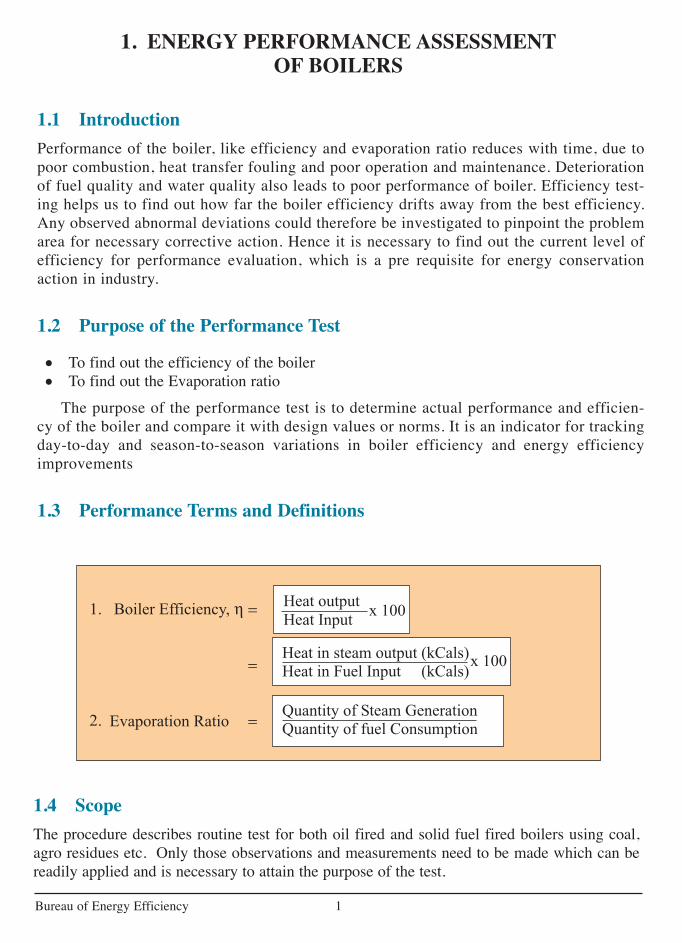
1.1 Introduction
Performance of the boiler, like efficiency and evaporation ratio reduces with time, due topoor combustion, heat transfer fouling and poor operation and maintenance. Deteriorationof fuel quality and water quality also leads to poor performance of boiler. Efficiency test-ing helps us to find out how far the boiler efficiency drifts away from the best efficiency.Any observed abnormal deviations could therefore be investigated to pinpoint the problemarea for necessary corrective action. Hence it is necessary to find out the current level ofefficiency for performance evaluation, which is a pre requisite for energy conservationaction in industry.
1.2 Purpose of the Performance Test
� To find out the efficiency of the boiler � To find out the Evaporation ratio
The purpose of the performance test is to determine actual performance and efficien-cy of the boiler and compare it with design values or norms. It is an indicator for trackingday-to-day and season-to-season variations in boiler efficiency and energy efficiencyimprovements
1.3 Performance Terms and Definitions
1.4 Scope
The procedure describes routine test for both oil fired and solid fuel fired boilers using coal,agro residues etc. Only those observations and measurements need to be made which can bereadily applied and is necessary to attain the purpose of the test.
1.5 Reference Standards
British standards, BS845: 1987
The British Standard BS845: 1987 describes the methods and conditions under which a boil-er should be tested to determine its efficiency. For the testing to be done, the boiler shouldbe operated under steady load conditions (generally full load) for a period of one hour afterwhich readings would be taken during the next hour of steady operation to enable the effi-ciency to be calculated.
The efficiency of a boiler is quoted as the % of useful heat available, expressed as a per-centage of the total energy potentially available by burning the fuel. This is expressed on thebasis of gross calorific value (GCV).
This deals with the complete heat balance and it has two parts:
� Part One deals with standard boilers, where the indirect method is specified� Part Two deals with complex plant where there are many channels of heat flow. In this
case, both the direct and indirect methods are applicable, in whole or in part.
ASME Standard: PTC-4-1 Power Test Code for Steam Generating Units
This consists of
� Part One: Direct method (also called as Input -output method)� Part Two: Indirect method (also called as Heat loss method)
IS 8753: Indian Standard for Boiler Efficiency Testing
Most standards for computation of boiler efficiency, including IS 8753 and BS845 are designedfor spot measurement of boiler efficiency. Invariably, all these standards do not include blowdown as a loss in the efficiency determination process.
Basically Boiler efficiency can be tested by the following methods:
1) The Direct Method: Where the energy gain of the working fluid (water and steam) iscompared with the energy content of the boiler fuel.
2) The Indirect Method: Where the efficiency is the difference between the losses and theenergy input.
1.6 The Direct Method Testing
1.6.1 Description
This is also known as 'input-output method' due to the fact that it needs only the useful output(steam) and the heat input (i.e. fuel) for evaluating the efficiency. This efficiency can be eval-uated using the formula:
1. Energy Performance Assessment of Boilers
2Bureau of Energy Efficiency
x 100
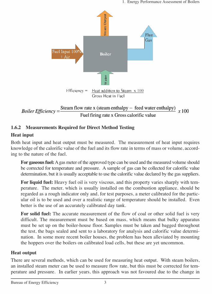
1.6.2 Measurements Required for Direct Method Testing
Heat input
Both heat input and heat output must be measured. The measurement of heat input requiresknowledge of the calorific value of the fuel and its flow rate in terms of mass or volume, accord-ing to the nature of the fuel.
For gaseous fuel:Agas meter of the approved type can be used and the measured volume shouldbe corrected for temperature and pressure. A sample of gas can be collected for calorific valuedetermination, but it is usually acceptable to use the calorific value declared by the gas suppliers.
For liquid fuel: Heavy fuel oil is very viscous, and this property varies sharply with tem-perature. The meter, which is usually installed on the combustion appliance, should beregarded as a rough indicator only and, for test purposes, a meter calibrated for the partic-ular oil is to be used and over a realistic range of temperature should be installed. Evenbetter is the use of an accurately calibrated day tank.
For solid fuel: The accurate measurement of the flow of coal or other solid fuel is verydifficult. The measurement must be based on mass, which means that bulky apparatusmust be set up on the boiler-house floor. Samples must be taken and bagged throughoutthe test, the bags sealed and sent to a laboratory for analysis and calorific value determi-nation. In some more recent boiler houses, the problem has been alleviated by mountingthe hoppers over the boilers on calibrated load cells, but these are yet uncommon.
Heat output
There are several methods, which can be used for measuring heat output. With steam boilers,an installed steam meter can be used to measure flow rate, but this must be corrected for tem-perature and pressure. In earlier years, this approach was not favoured due to the change in
1. Energy Performance Assessment of Boilers
3Bureau of Energy Efficiency
accuracy of orifice or venturi meters with flow rate. It is now more viable with modern flowmeters of the variable-orifice or vortex-shedding types.
The alternative with small boilers is to measure feed water, and this can be done by previ-ously calibrating the feed tank and noting down the levels of water during the beginning andend of the trial. Care should be taken not to pump water during this period. Heat addition forconversion of feed water at inlet temperature to steam, is considered for heat output.
In case of boilers with intermittent blowdown, blowdown should be avoided during the trialperiod. In case of boilers with continuous blowdown, the heat loss due to blowdown should becalculated and added to the heat in steam.
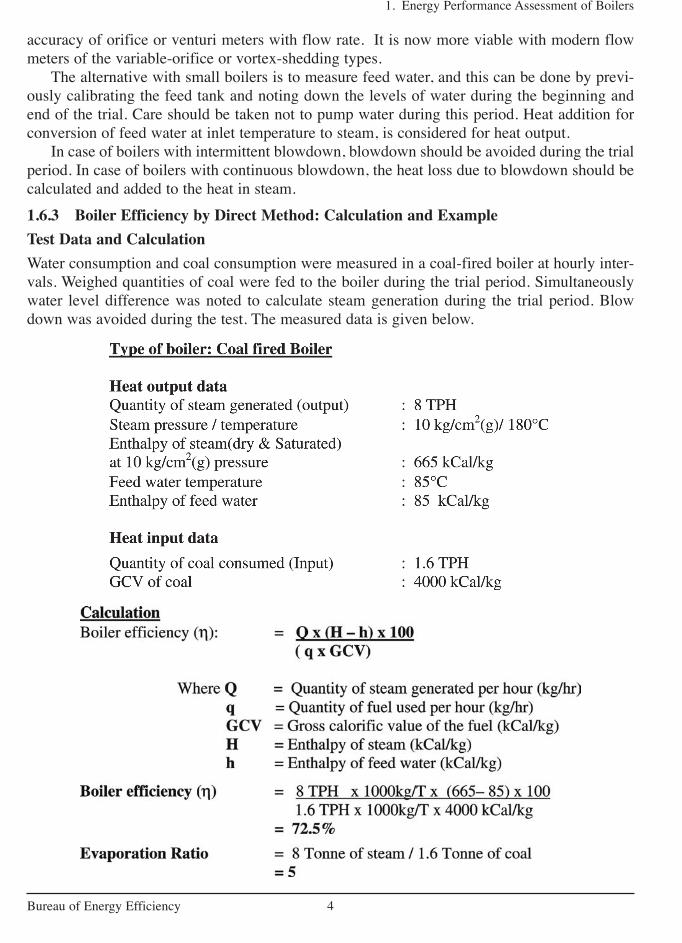
1.6.3 Boiler Efficiency by Direct Method: Calculation and Example
Test Data and Calculation
Water consumption and coal consumption were measured in a coal-fired boiler at hourly inter-vals. Weighed quantities of coal were fed to the boiler during the trial period. Simultaneouslywater level difference was noted to calculate steam generation during the trial period. Blowdown was avoided during the test. The measured data is given below.
1. Energy Performance Assessment of Boilers
4Bureau of Energy Efficiency

1.6.4 Merits and Demerits of Direct Method
Merits
� Plant people can evaluate quickly the efficiency of boilers� Requires few parameters for computation� Needs few instruments for monitoring
Demerits
� Does not give clues to the operator as to why efficiency of system is lower� Does not calculate various losses accountable for various efficiency levels� Evaporation ratio and efficiency may mislead, if the steam is highly wet due to water carryover
1.7 The Indirect Method Testing
1.7.1 Description
The efficiency can be measured easily by measuring all the losses occurring in the boilers usingthe principles to be described. The disadvantages of the direct method can be overcome by thismethod, which calculates the various heat losses associated with boiler. The efficiency can bearrived at, by subtracting the heat loss fractions from 100.An important advantage of thismethod is that the errors in measurement do not make significant change in efficiency.
Thus if boiler efficiency is 90% , an error of 1% in direct method will result in significantchange in efficiency. i.e. 90 ± 0.9 = 89.1 to 90.9. In indirect method, 1% error in measurementof losses will result in
Efficiency = 100 � (10 ± 0.1) = 90 ± 0.1 = 89.9 to 90.1
The various heat losses occurring in the boiler are:
1. Energy Performance Assessment of Boilers
5Bureau of Energy Efficiency
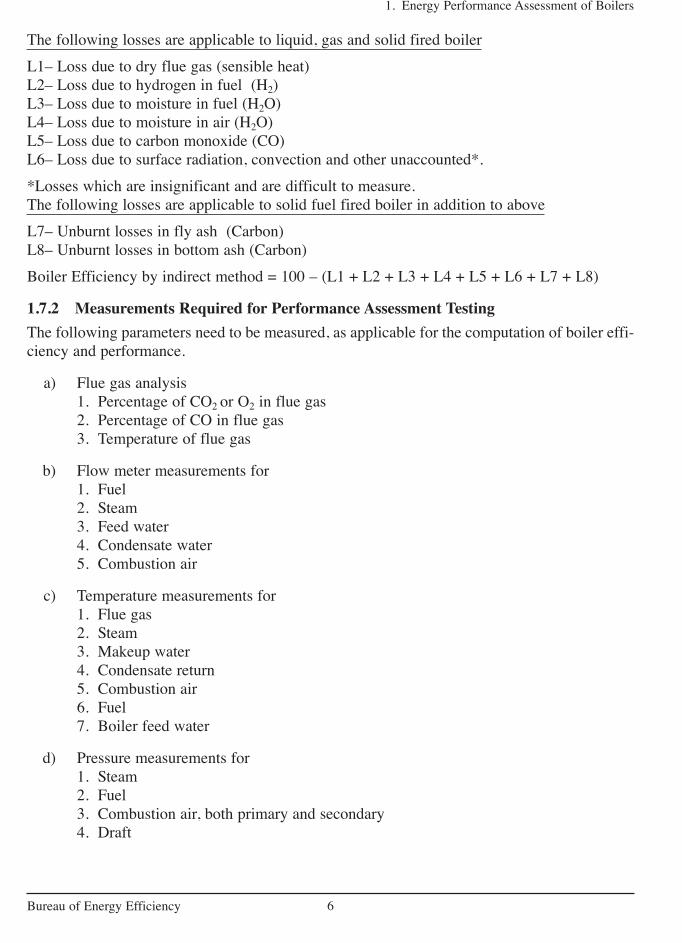
The following losses are applicable to liquid, gas and solid fired boiler
L1� Loss due to dry flue gas (sensible heat)L2� Loss due to hydrogen in fuel (H2)L3� Loss due to moisture in fuel (H2O)L4� Loss due to moisture in air (H2O)L5� Loss due to carbon monoxide (CO)L6� Loss due to surface radiation, convection and other unaccounted*.
*Losses which are insignificant and are difficult to measure.The following losses are applicable to solid fuel fired boiler in addition to above
L7� Unburnt losses in fly ash (Carbon)L8� Unburnt losses in bottom ash (Carbon)
Boiler Efficiency by indirect method = 100 � (L1 + L2 + L3 + L4 + L5 + L6 + L7 + L8)
1.7.2 Measurements Required for Performance Assessment Testing
The following parameters need to be measured, as applicable for the computation of boiler effi-ciency and performance.
a) Flue gas analysis1. Percentage of CO2 or O2 in flue gas 2. Percentage of CO in flue gas3. Temperature of flue gas
b) Flow meter measurements for1. Fuel 2. Steam 3. Feed water 4. Condensate water 5. Combustion air
c) Temperature measurements for1. Flue gas 2. Steam 3. Makeup water 4. Condensate return 5. Combustion air 6. Fuel 7. Boiler feed water
d) Pressure measurements for1. Steam2. Fuel3. Combustion air, both primary and secondary4. Draft
1. Energy Performance Assessment of Boilers
6Bureau of Energy Efficiency
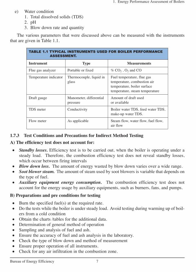
1.7.3 Test Conditions and Precautions for Indirect Method Testing
A) The efficiency test does not account for:
� Standby losses. Efficiency test is to be carried out, when the boiler is operating under asteady load. Therefore, the combustion efficiency test does not reveal standby losses,which occur between firing intervals
� Blow down loss. The amount of energy wasted by blow down varies over a wide range.� Soot blower steam. The amount of steam used by soot blowers is variable that depends on
the type of fuel.� Auxiliary equipment energy consumption. The combustion efficiency test does not
account for the energy usage by auxiliary equipments, such as burners, fans, and pumps.
B) Preparations and pre conditions for testing
� Burn the specified fuel(s) at the required rate.� Do the tests while the boiler is under steady load. Avoid testing during warming up of boil-
ers from a cold condition� Obtain the charts /tables for the additional data.� Determination of general method of operation� Sampling and analysis of fuel and ash.� Ensure the accuracy of fuel and ash analysis in the laboratory.� Check the type of blow down and method of measurement� Ensure proper operation of all instruments.� Check for any air infiltration in the combustion zone.
1. Energy Performance Assessment of Boilers
7Bureau of Energy Efficiency
TABLE 1.1 TYPICAL INSTRUMENTS USED FOR BOILER PERFORMANCE
ASSESSMENT.
Instrument Type Measurements
Flue gas analyzer Portable or fixed % CO2 , O2 and CO
Temperature indicator Thermocouple, liquid in Fuel temperature, flue gasglass temperature, combustion air
temperature, boiler surfacetemperature, steam temperature
Draft gauge Manometer, differential Amount of draft usedpressure or available
TDS meter Conductivity Boiler water TDS, feed water TDS,make-up water TDS.
Flow meter As applicable Steam flow, water flow, fuel flow,air flow
e) Water condition1. Total dissolved solids (TDS)2. pH3. Blow down rate and quantity
The various parameters that were discussed above can be measured with the instrumentsthat are given in Table 1.1.
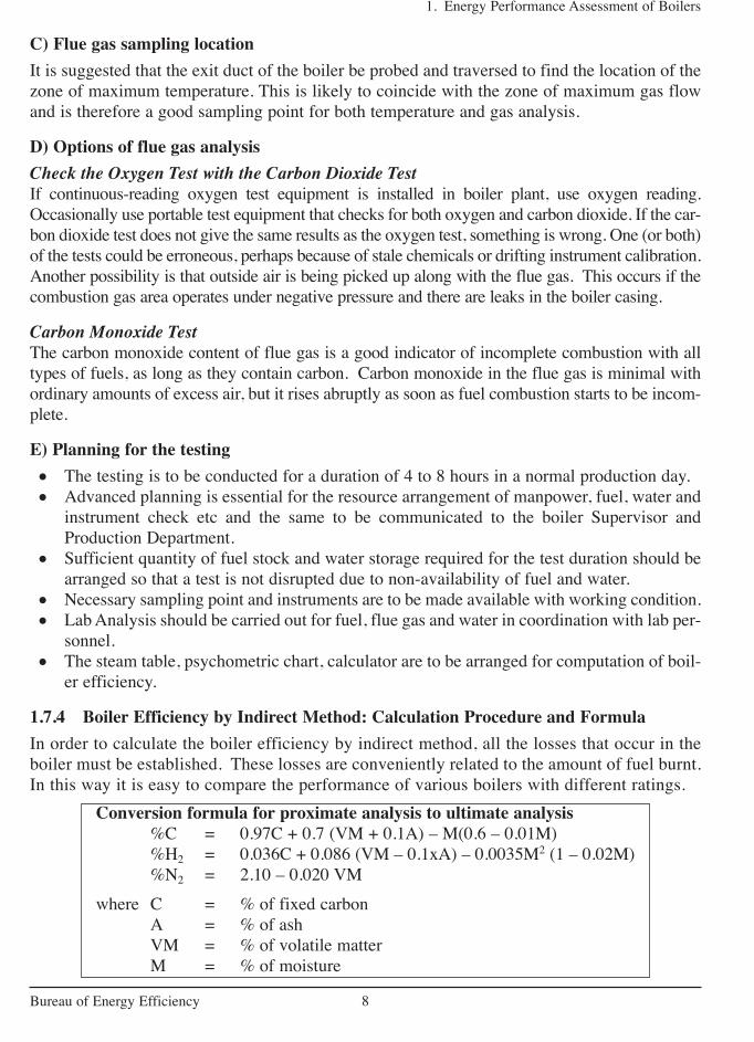
C) Flue gas sampling location
It is suggested that the exit duct of the boiler be probed and traversed to find the location of thezone of maximum temperature. This is likely to coincide with the zone of maximum gas flowand is therefore a good sampling point for both temperature and gas analysis.
D) Options of flue gas analysis
Check the Oxygen Test with the Carbon Dioxide TestIf continuous-reading oxygen test equipment is installed in boiler plant, use oxygen reading.Occasionally use portable test equipment that checks for both oxygen and carbon dioxide. If the car-bon dioxide test does not give the same results as the oxygen test, something is wrong. One (or both)of the tests could be erroneous, perhaps because of stale chemicals or drifting instrument calibration.Another possibility is that outside air is being picked up along with the flue gas. This occurs if thecombustion gas area operates under negative pressure and there are leaks in the boiler casing.
Carbon Monoxide TestThe carbon monoxide content of flue gas is a good indicator of incomplete combustion with alltypes of fuels, as long as they contain carbon. Carbon monoxide in the flue gas is minimal withordinary amounts of excess air, but it rises abruptly as soon as fuel combustion starts to be incom-plete.
E) Planning for the testing
� The testing is to be conducted for a duration of 4 to 8 hours in a normal production day.� Advanced planning is essential for the resource arrangement of manpower, fuel, water and
instrument check etc and the same to be communicated to the boiler Supervisor andProduction Department.
� Sufficient quantity of fuel stock and water storage required for the test duration should bearranged so that a test is not disrupted due to non-availability of fuel and water.
� Necessary sampling point and instruments are to be made available with working condition.� Lab Analysis should be carried out for fuel, flue gas and water in coordination with lab per-
sonnel.� The steam table, psychometric chart, calculator are to be arranged for computation of boil-
er efficiency.
1.7.4 Boiler Efficiency by Indirect Method: Calculation Procedure and Formula
In order to calculate the boiler efficiency by indirect method, all the losses that occur in theboiler must be established. These losses are conveniently related to the amount of fuel burnt.In this way it is easy to compare the performance of various boilers with different ratings.
1. Energy Performance Assessment of Boilers
8Bureau of Energy Efficiency
Conversion formula for proximate analysis to ultimate analysis%C = 0.97C + 0.7 (VM + 0.1A) � M(0.6 � 0.01M)%H2 = 0.036C + 0.086 (VM � 0.1xA) � 0.0035M2 (1 � 0.02M)%N2 = 2.10 � 0.020 VM
where C = % of fixed carbon A = % of ashVM = % of volatile matterM = % of moisture
The various losses associated with the operation of a boiler are discussed below withrequired formula.
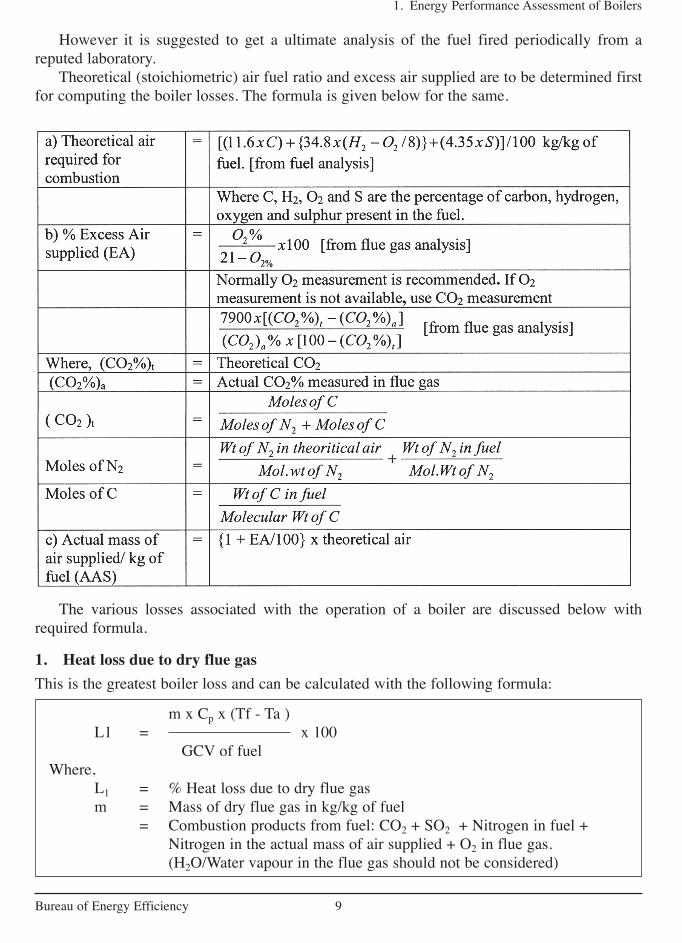
1. Heat loss due to dry flue gas
This is the greatest boiler loss and can be calculated with the following formula:
1. Energy Performance Assessment of Boilers
9Bureau of Energy Efficiency
However it is suggested to get a ultimate analysis of the fuel fired periodically from a reputed laboratory.
Theoretical (stoichiometric) air fuel ratio and excess air supplied are to be determined firstfor computing the boiler losses. The formula is given below for the same.
m x Cp x (Tf - Ta )L1 = x 100
GCV of fuelWhere,
L1 = % Heat loss due to dry flue gasm = Mass of dry flue gas in kg/kg of fuel
= Combustion products from fuel: CO2 + SO2 + Nitrogen in fuel +Nitrogen in the actual mass of air supplied + O2 in flue gas.(H2O/Water vapour in the flue gas should not be considered)
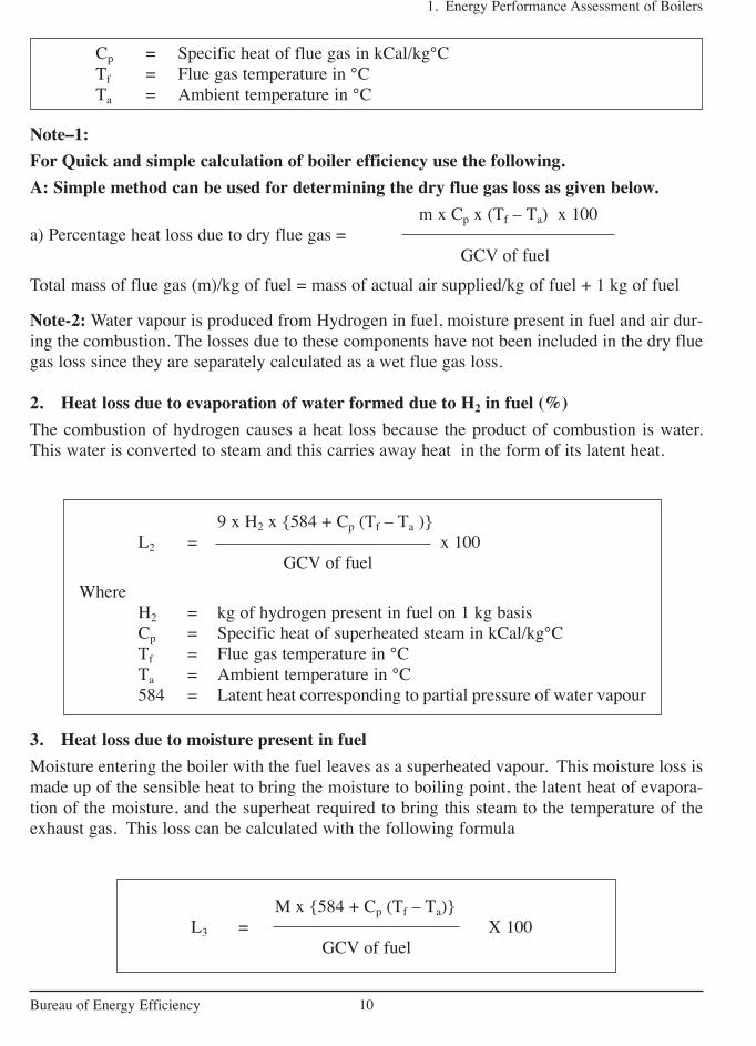
3. Heat loss due to moisture present in fuel
Moisture entering the boiler with the fuel leaves as a superheated vapour. This moisture loss ismade up of the sensible heat to bring the moisture to boiling point, the latent heat of evapora-tion of the moisture, and the superheat required to bring this steam to the temperature of theexhaust gas. This loss can be calculated with the following formula
1. Energy Performance Assessment of Boilers
10Bureau of Energy Efficiency
Cp = Specific heat of flue gas in kCal/kg°CTf = Flue gas temperature in °CTa = Ambient temperature in °C
Note�1:
For Quick and simple calculation of boiler efficiency use the following.
A: Simple method can be used for determining the dry flue gas loss as given below.
m x Cp x (Tf � Ta) x 100a) Percentage heat loss due to dry flue gas =
GCV of fuel
Total mass of flue gas (m)/kg of fuel = mass of actual air supplied/kg of fuel + 1 kg of fuel
Note-2: Water vapour is produced from Hydrogen in fuel, moisture present in fuel and air dur-ing the combustion. The losses due to these components have not been included in the dry fluegas loss since they are separately calculated as a wet flue gas loss.
2. Heat loss due to evaporation of water formed due to H2 in fuel (%)
The combustion of hydrogen causes a heat loss because the product of combustion is water.This water is converted to steam and this carries away heat in the form of its latent heat.
9 x H2 x {584 + Cp (Tf � Ta )} L2 = x 100
GCV of fuel
WhereH2 = kg of hydrogen present in fuel on 1 kg basisCp = Specific heat of superheated steam in kCal/kg°CTf = Flue gas temperature in °CTa = Ambient temperature in °C584 = Latent heat corresponding to partial pressure of water vapour
M x {584 + Cp (Tf � Ta)} L3 = X 100
GCV of fuel
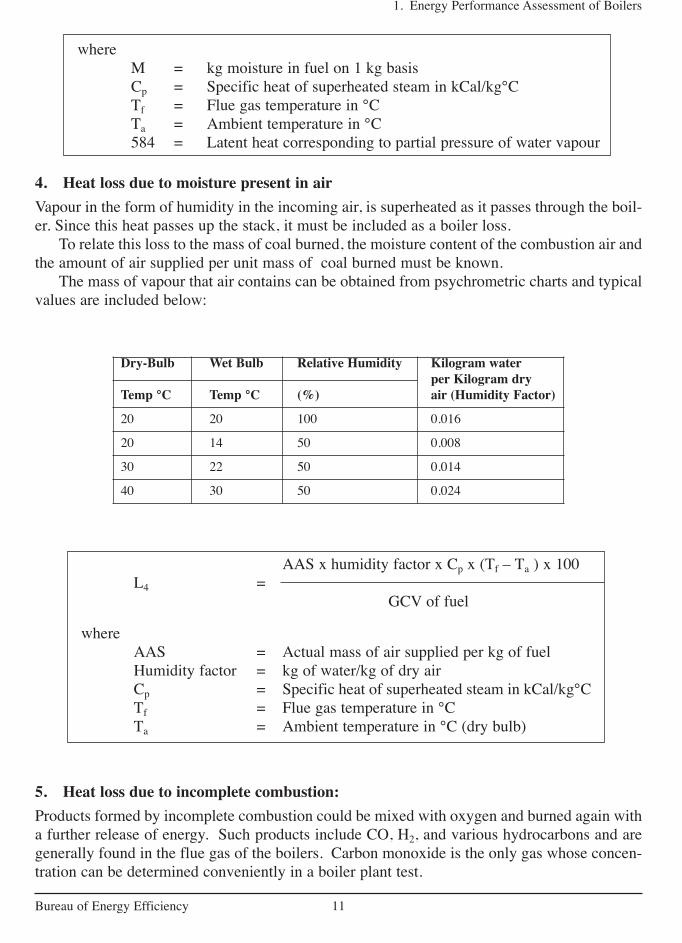
4. Heat loss due to moisture present in air
Vapour in the form of humidity in the incoming air, is superheated as it passes through the boil-er. Since this heat passes up the stack, it must be included as a boiler loss.
To relate this loss to the mass of coal burned, the moisture content of the combustion air andthe amount of air supplied per unit mass of coal burned must be known.
The mass of vapour that air contains can be obtained from psychrometric charts and typicalvalues are included below:
1. Energy Performance Assessment of Boilers
11Bureau of Energy Efficiency
whereM = kg moisture in fuel on 1 kg basisCp = Specific heat of superheated steam in kCal/kg°CTf = Flue gas temperature in °CTa = Ambient temperature in °C584 = Latent heat corresponding to partial pressure of water vapour
Dry-Bulb Wet Bulb Relative Humidity Kilogram waterper Kilogram dry
Temp °C Temp °C (%) air (Humidity Factor)
20 20 100 0.016
20 14 50 0.008
30 22 50 0.014
40 30 50 0.024
AAS x humidity factor x Cp x (Tf � Ta ) x 100L4 =
GCV of fuel
whereAAS = Actual mass of air supplied per kg of fuelHumidity factor = kg of water/kg of dry airCp = Specific heat of superheated steam in kCal/kg°CTf = Flue gas temperature in °CTa = Ambient temperature in °C (dry bulb)
5. Heat loss due to incomplete combustion:
Products formed by incomplete combustion could be mixed with oxygen and burned again witha further release of energy. Such products include CO, H2, and various hydrocarbons and aregenerally found in the flue gas of the boilers. Carbon monoxide is the only gas whose concen-tration can be determined conveniently in a boiler plant test.
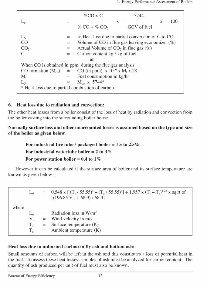
6. Heat loss due to radiation and convection:
The other heat losses from a boiler consist of the loss of heat by radiation and convection fromthe boiler casting into the surrounding boiler house.
Normally surface loss and other unaccounted losses is assumed based on the type and sizeof the boiler as given below
For industrial fire tube / packaged boiler = 1.5 to 2.5%
For industrial watertube boiler = 2 to 3%
For power station boiler = 0.4 to 1%
However it can be calculated if the surface area of boiler and its surface temperature areknown as given below :
1. Energy Performance Assessment of Boilers
12Bureau of Energy Efficiency
%CO x C 5744L5 = x x 100
% CO + % CO2 GCV of fuel
L5 = % Heat loss due to partial conversion of C to COCO = Volume of CO in flue gas leaving economizer (%)CO2 = Actual Volume of CO2 in flue gas (%)C = Carbon content kg / kg of fuel
orWhen CO is obtained in ppm during the flue gas analysisCO formation (Mco) = CO (in ppm) x 10�6 x Mf x 28Mf = Fuel consumption in kg/hrL5 = Mco x 5744** Heat loss due to partial combustion of carbon.
L6 = 0.548 x [ (Ts / 55.55)4 � (Ta / 55.55)4] + 1.957 x (Ts � Ta)1.25 x sq.rt of[(196.85 Vm + 68.9) / 68.9]
whereL6 = Radiation loss in W/m2
Vm = Wind velocity in m/sTs = Surface temperature (K)Ta = Ambient temperature (K)
Heat loss due to unburned carbon in fly ash and bottom ash:
Small amounts of carbon will be left in the ash and this constitutes a loss of potential heat inthe fuel. To assess these heat losses, samples of ash must be analyzed for carbon content. Thequantity of ash produced per unit of fuel must also be known.
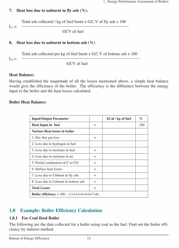
7. Heat loss due to unburnt in fly ash (%).
Total ash collected / kg of fuel burnt x G.C.V of fly ash x 100L7 =
GCV of fuel
8. Heat loss due to unburnt in bottom ash (%)
Total ash collected per kg of fuel burnt x G.C.V of bottom ash x 100L8 =
GCV of fuel
Heat Balance:
Having established the magnitude of all the losses mentioned above, a simple heat balancewould give the efficiency of the boiler. The efficiency is the difference between the energyinput to the boiler and the heat losses calculated.
Boiler Heat Balance:
1. Energy Performance Assessment of Boilers
13Bureau of Energy Efficiency
Input/Output Parameter kCal / kg of fuel %
Heat Input in fuel = 100
Various Heat losses in boiler
1. Dry flue gas loss =
2. Loss due to hydrogen in fuel
3. Loss due to moisture in fuel =
4. Loss due to moisture in air =
5. Partial combustion of C to CO =
6. Surface heat losses =
7. Loss due to Unburnt in fly ash =
8. Loss due to Unburnt in bottom ash =
Total Losses =
Boiler efficiency = 100 � (1+2+3+4+5+6+7+8)
1.8 Example: Boiler Efficiency Calculation
1.8.1 For Coal fired Boiler
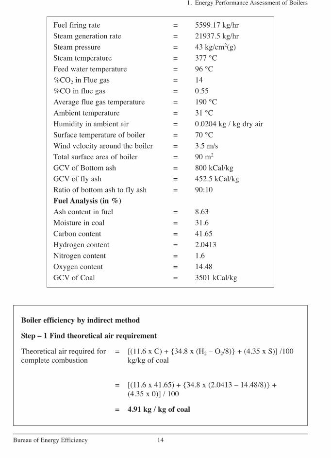
The following are the data collected for a boiler using coal as the fuel. Find out the boiler effi-ciency by indirect method.
1. Energy Performance Assessment of Boilers
14Bureau of Energy Efficiency
Fuel firing rate = 5599.17 kg/hr
Steam generation rate = 21937.5 kg/hr
Steam pressure = 43 kg/cm2(g)
Steam temperature = 377 °C
Feed water temperature = 96 °C
%CO2 in Flue gas = 14
%CO in flue gas = 0.55
Average flue gas temperature = 190 °C
Ambient temperature = 31 °C
Humidity in ambient air = 0.0204 kg / kg dry air
Surface temperature of boiler = 70 °C
Wind velocity around the boiler = 3.5 m/s
Total surface area of boiler = 90 m2
GCV of Bottom ash = 800 kCal/kg
GCV of fly ash = 452.5 kCal/kg
Ratio of bottom ash to fly ash = 90:10
Fuel Analysis (in %)Ash content in fuel = 8.63
Moisture in coal = 31.6
Carbon content = 41.65
Hydrogen content = 2.0413
Nitrogen content = 1.6
Oxygen content = 14.48
GCV of Coal = 3501 kCal/kg
Boiler efficiency by indirect method
Step � 1 Find theoretical air requirement
Theoretical air required for = [(11.6 x C) + {34.8 x (H2 � O2/8)} + (4.35 x S)] /100complete combustion kg/kg of coal
= [(11.6 x 41.65) + {34.8 x (2.0413 � 14.48/8)} +(4.35 x 0)] / 100
= 4.91 kg / kg of coal
1. Energy Performance Assessment of Boilers
15Bureau of Energy Efficiency
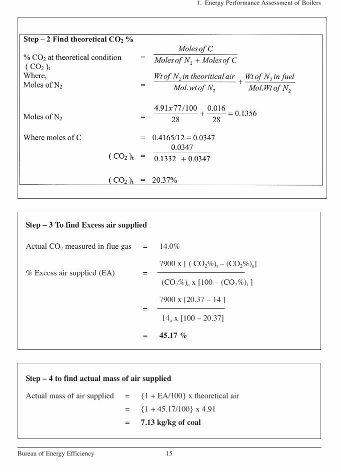
Step � 3 To find Excess air supplied
Actual CO2 measured in flue gas = 14.0%
7900 x [ ( CO2%)t � (CO2%)a]% Excess air supplied (EA) =
(CO2%)a x [100 � (CO2%)t ]
7900 x [20.37 � 14 ]=
14a x [100 � 20.37]
= 45.17 %
Step � 4 to find actual mass of air supplied
Actual mass of air supplied = {1 + EA/100} x theoretical air
= {1 + 45.17/100} x 4.91
= 7.13 kg/kg of coal
1. Energy Performance Assessment of Boilers
16Bureau of Energy Efficiency
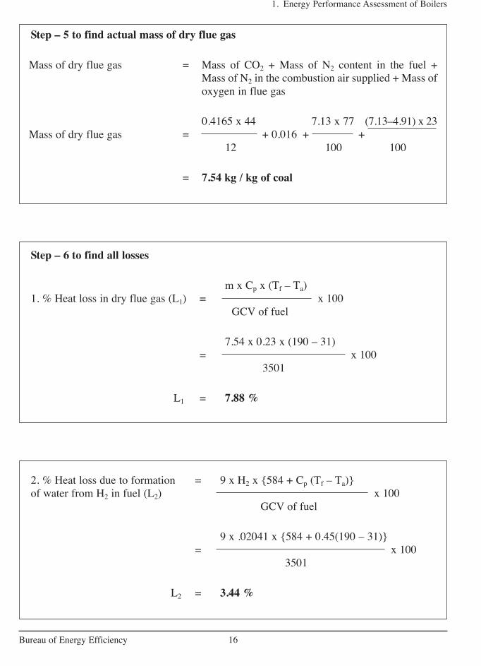
Step � 5 to find actual mass of dry flue gas
Mass of dry flue gas = Mass of CO2 + Mass of N2 content in the fuel +Mass of N2 in the combustion air supplied + Mass ofoxygen in flue gas
0.4165 x 44 7.13 x 77 (7.13�4.91) x 23Mass of dry flue gas = + 0.016 + +
12 100 100
= 7.54 kg / kg of coal
Step � 6 to find all losses
m x Cp x (Tf � Ta) 1. % Heat loss in dry flue gas (L1) = x 100
GCV of fuel
7.54 x 0.23 x (190 � 31)= x 100
3501
L1 = 7.88 %
2. % Heat loss due to formation = 9 x H2 x {584 + Cp (Tf � Ta)} of water from H2 in fuel (L2) x 100
GCV of fuel
9 x .02041 x {584 + 0.45(190 � 31)} = x 100
3501
L2 = 3.44 %
1. Energy Performance Assessment of Boilers
17Bureau of Energy Efficiency
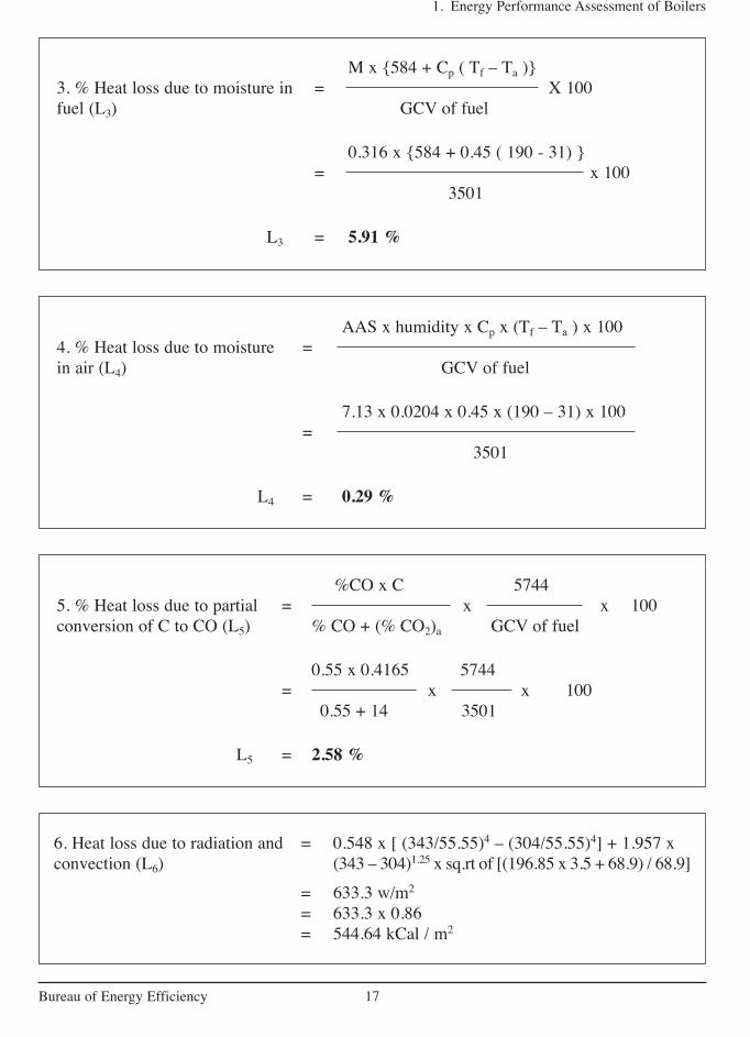
M x {584 + Cp ( Tf � Ta )}3. % Heat loss due to moisture in = X 100fuel (L3) GCV of fuel
0.316 x {584 + 0.45 ( 190 - 31) }= x 100
3501
L3 = 5.91 %
AAS x humidity x Cp x (Tf � Ta ) x 1004. % Heat loss due to moisture =in air (L4) GCV of fuel
7.13 x 0.0204 x 0.45 x (190 � 31) x 100=
3501
L4 = 0.29 %
%CO x C 57445. % Heat loss due to partial = x x 100conversion of C to CO (L5) % CO + (% CO2)a GCV of fuel
0.55 x 0.4165 5744= x x 100
0.55 + 14 3501
L5 = 2.58 %
6. Heat loss due to radiation and = 0.548 x [ (343/55.55)4 � (304/55.55)4] + 1.957 xconvection (L6) (343 � 304)1.25 x sq.rt of [(196.85 x 3.5 + 68.9) / 68.9]
= 633.3 w/m2
= 633.3 x 0.86= 544.64 kCal / m2
1. Energy Performance Assessment of Boilers
18Bureau of Energy Efficiency
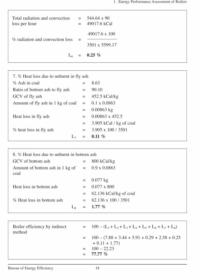
Total radiation and convection = 544.64 x 90loss per hour = 49017.6 kCal
49017.6 x 100% radiation and convection loss =
3501 x 5599.17
L6 = 0.25 %
7. % Heat loss due to unburnt in fly ash
% Ash in coal = 8.63
Ratio of bottom ash to fly ash = 90:10
GCV of fly ash = 452.5 kCal/kg
Amount of fly ash in 1 kg of coal = 0.1 x 0.0863
= 0.00863 kg
Heat loss in fly ash = 0.00863 x 452.5
= 3.905 kCal / kg of coal
% heat loss in fly ash = 3.905 x 100 / 3501
L7 = 0.11 %
8. % Heat loss due to unburnt in bottom ash
GCV of bottom ash = 800 kCal/kg
Amount of bottom ash in 1 kg of = 0.9 x 0.0863coal
= 0.077 kg
Heat loss in bottom ash = 0.077 x 800
= 62.136 kCal/kg of coal
% Heat loss in bottom ash = 62.136 x 100 / 3501
L8 = 1.77 %
Boiler efficiency by indirect = 100 � (L1 + L2 + L3 + L4 + L5 + L6 + L7 + L8)method
= 100 � (7.88 + 3.44 + 5.91 + 0.29 + 2.58 + 0.25+ 0.11 + 1.77)
= 100 � 22.23= 77.77 %
1.8.2 Efficiency for an oil fired boiler
The following are the data collected for a boiler using furnace oil as the fuel. Find out the boil-er efficiency by indirect method.
1. Energy Performance Assessment of Boilers
19Bureau of Energy Efficiency
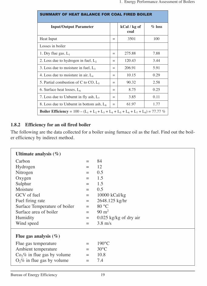
SUMMARY OF HEAT BALANCE FOR COAL FIRED BOILER
Input/Output Parameter kCal / kg of % losscoal
Heat Input = 3501 100
Losses in boiler
1. Dry flue gas, L1 = 275.88 7.88
2. Loss due to hydrogen in fuel, L2 = 120.43 3.44
3. Loss due to moisture in fuel, L3 = 206.91 5.91
4. Loss due to moisture in air, L4 = 10.15 0.29
5. Partial combustion of C to CO, L5 = 90.32 2.58
6. Surface heat losses, L6 = 8.75 0.25
7. Loss due to Unburnt in fly ash, L7 = 3.85 0.11
8. Loss due to Unburnt in bottom ash, L8 = 61.97 1.77
Boiler Efficiency = 100 � (L1 + L2 + L3 + L4 + L5 + L6 + L7 + L8) = 77.77 %
Ultimate analysis (%)
Carbon = 84Hydrogen = 12Nitrogen = 0.5Oxygen = 1.5Sulphur = 1.5Moisture = 0.5GCV of fuel = 10000 kCal/kgFuel firing rate = 2648.125 kg/hrSurface Temperature of boiler = 80 °CSurface area of boiler = 90 m2
Humidity = 0.025 kg/kg of dry airWind speed = 3.8 m/s
Flue gas analysis (%)
Flue gas temperature = 190°CAmbient temperature = 30°CCo2% in flue gas by volume = 10.8O2% in flue gas by volume = 7.4
1. Energy Performance Assessment of Boilers
20Bureau of Energy Efficiency
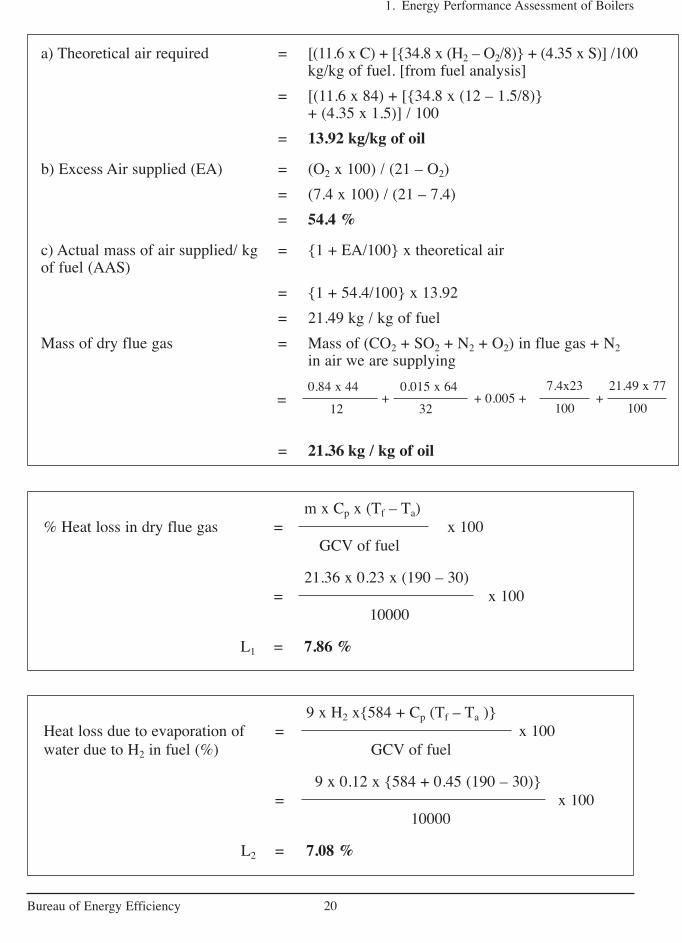
a) Theoretical air required = [(11.6 x C) + [{34.8 x (H2 � O2/8)} + (4.35 x S)] /100kg/kg of fuel. [from fuel analysis]
= [(11.6 x 84) + [{34.8 x (12 � 1.5/8)}+ (4.35 x 1.5)] / 100
= 13.92 kg/kg of oil
b) Excess Air supplied (EA) = (O2 x 100) / (21 � O2)
= (7.4 x 100) / (21 � 7.4)
= 54.4 %
c) Actual mass of air supplied/ kg = {1 + EA/100} x theoretical airof fuel (AAS)
= {1 + 54.4/100} x 13.92
= 21.49 kg / kg of fuel
Mass of dry flue gas = Mass of (CO2 + SO2 + N2 + O2) in flue gas + N2in air we are supplying
0.84 x 44 0.015 x 64
12 32
= 21.36 kg / kg of oil
m x Cp x (Tf � Ta)% Heat loss in dry flue gas = x 100
GCV of fuel
21.36 x 0.23 x (190 � 30)= x 100
10000
L1 = 7.86 %
9 x H2 x{584 + Cp (Tf � Ta )}Heat loss due to evaporation of = x 100water due to H2 in fuel (%) GCV of fuel
9 x 0.12 x {584 + 0.45 (190 � 30)}= x 100
10000
L2 = 7.08 %
+ 0.005 + + 7.4x23
100
21.49 x 77
100+=
1. Energy Performance Assessment of Boilers
21Bureau of Energy Efficiency
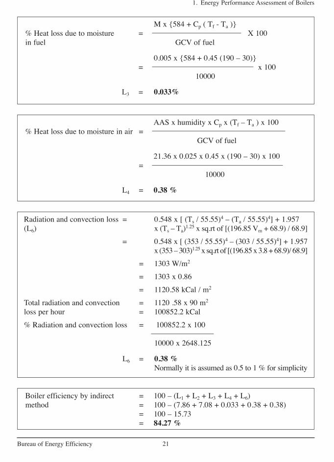
M x {584 + Cp ( Tf - Ta )}% Heat loss due to moisture = X 100in fuel GCV of fuel
0.005 x {584 + 0.45 (190 � 30)}= x 100
10000
L3 = 0.033%
AAS x humidity x Cp x (Tf � Ta ) x 100% Heat loss due to moisture in air =
GCV of fuel
21.36 x 0.025 x 0.45 x (190 � 30) x 100=
10000
L4 = 0.38 %
Radiation and convection loss = 0.548 x [ (Ts / 55.55)4 � (Ta / 55.55)4] + 1.957 (L6) x (Ts � Ta)1.25 x sq.rt of [(196.85 Vm + 68.9) / 68.9]
= 0.548 x [ (353 / 55.55)4 � (303 / 55.55)4] + 1.957x (353 � 303)1.25 x sq.rt of [(196.85 x 3.8 + 68.9)/ 68.9]
= 1303 W/m2
= 1303 x 0.86
= 1120.58 kCal / m2
Total radiation and convection = 1120 .58 x 90 m2
loss per hour = 100852.2 kCal
% Radiation and convection loss = 100852.2 x 100
10000 x 2648.125
L6 = 0.38 %Normally it is assumed as 0.5 to 1 % for simplicity
Boiler efficiency by indirect = 100 � (L1 + L2 + L3 + L4 + L6)method = 100 � (7.86 + 7.08 + 0.033 + 0.38 + 0.38)
= 100 � 15.73= 84.27 %
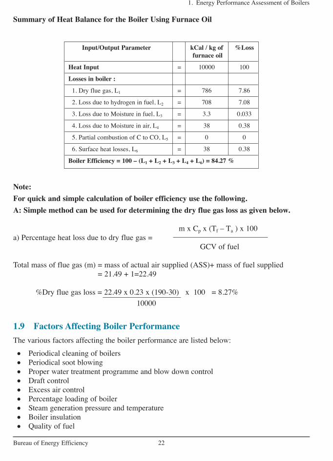
Summary of Heat Balance for the Boiler Using Furnace Oil
1. Energy Performance Assessment of Boilers
22Bureau of Energy Efficiency
Input/Output Parameter kCal / kg of %Lossfurnace oil
Heat Input = 10000 100
Losses in boiler :
1. Dry flue gas, L1 = 786 7.86
2. Loss due to hydrogen in fuel, L2 = 708 7.08
3. Loss due to Moisture in fuel, L3 = 3.3 0.033
4. Loss due to Moisture in air, L4 = 38 0.38
5. Partial combustion of C to CO, L5 = 0 0
6. Surface heat losses, L6 = 38 0.38
Boiler Efficiency = 100 � (L1 + L2 + L3 + L4 + L6) = 84.27 %
Note:
For quick and simple calculation of boiler efficiency use the following.
A: Simple method can be used for determining the dry flue gas loss as given below.
m x Cp x (Tf � Ta ) x 100a) Percentage heat loss due to dry flue gas =
GCV of fuel
Total mass of flue gas (m) = mass of actual air supplied (ASS)+ mass of fuel supplied= 21.49 + 1=22.49
%Dry flue gas loss = 22.49 x 0.23 x (190-30) x 100 = 8.27%
10000
1.9 Factors Affecting Boiler Performance
The various factors affecting the boiler performance are listed below:
� Periodical cleaning of boilers � Periodical soot blowing � Proper water treatment programme and blow down control� Draft control� Excess air control� Percentage loading of boiler� Steam generation pressure and temperature � Boiler insulation� Quality of fuel
All these factors individually/combined, contribute to the performance of the boiler andreflected either in boiler efficiency or evaporation ratio. Based on the results obtained from thetesting further improvements have to be carried out for maximizing the performance. The testcan be repeated after modification or rectification of the problems and compared with standardnorms. Energy auditor should carry out this test as a routine manner once in six months andreport to the management for necessary action.
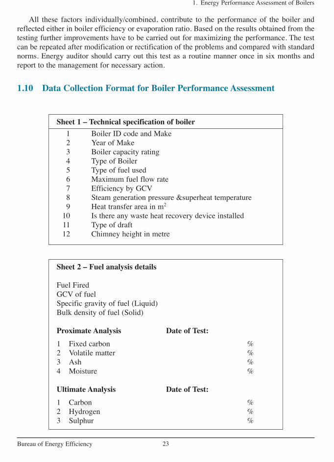
1.10 Data Collection Format for Boiler Performance Assessment
1. Energy Performance Assessment of Boilers
23Bureau of Energy Efficiency
Sheet 1 � Technical specification of boiler
1 Boiler ID code and Make2 Year of Make3 Boiler capacity rating4 Type of Boiler5 Type of fuel used6 Maximum fuel flow rate7 Efficiency by GCV8 Steam generation pressure &superheat temperature9 Heat transfer area in m2
10 Is there any waste heat recovery device installed11 Type of draft12 Chimney height in metre
Sheet 2 � Fuel analysis details
Fuel FiredGCV of fuelSpecific gravity of fuel (Liquid)Bulk density of fuel (Solid)
Proximate Analysis Date of Test:
1 Fixed carbon %2 Volatile matter %3 Ash %4 Moisture %
Ultimate Analysis Date of Test:
1 Carbon %2 Hydrogen %3 Sulphur %
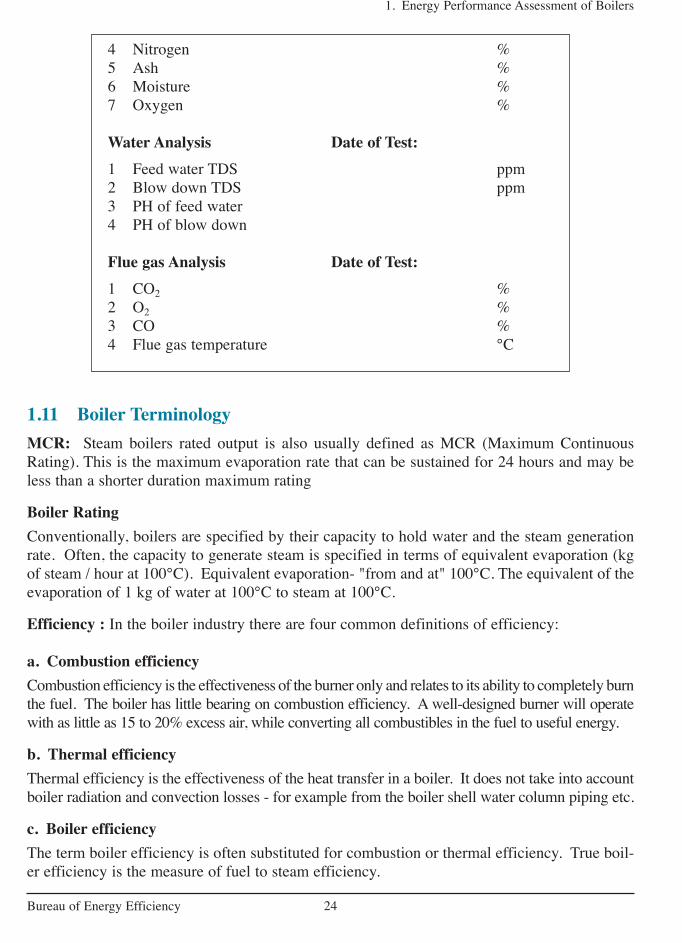
1.11 Boiler Terminology
MCR: Steam boilers rated output is also usually defined as MCR (Maximum ContinuousRating). This is the maximum evaporation rate that can be sustained for 24 hours and may beless than a shorter duration maximum rating
Boiler Rating
Conventionally, boilers are specified by their capacity to hold water and the steam generationrate. Often, the capacity to generate steam is specified in terms of equivalent evaporation (kgof steam / hour at 100°C). Equivalent evaporation- "from and at" 100°C. The equivalent of theevaporation of 1 kg of water at 100°C to steam at 100°C.
Efficiency : In the boiler industry there are four common definitions of efficiency:
a. Combustion efficiency
Combustion efficiency is the effectiveness of the burner only and relates to its ability to completely burnthe fuel. The boiler has little bearing on combustion efficiency. A well-designed burner will operatewith as little as 15 to 20% excess air, while converting all combustibles in the fuel to useful energy.
b. Thermal efficiency
Thermal efficiency is the effectiveness of the heat transfer in a boiler. It does not take into accountboiler radiation and convection losses - for example from the boiler shell water column piping etc.
c. Boiler efficiency
The term boiler efficiency is often substituted for combustion or thermal efficiency. True boil-er efficiency is the measure of fuel to steam efficiency.
1. Energy Performance Assessment of Boilers
24Bureau of Energy Efficiency
4 Nitrogen %5 Ash %6 Moisture %7 Oxygen %
Water Analysis Date of Test:
1 Feed water TDS ppm2 Blow down TDS ppm3 PH of feed water4 PH of blow down
Flue gas Analysis Date of Test:
1 CO2 %2 O2 %3 CO %4 Flue gas temperature °C

1.E
nerg
y Pe
rfor
man
ce A
sses
smen
t of
Boi
lers
25B
urea
u of
Ene
rgy
Eff
icie
ncy
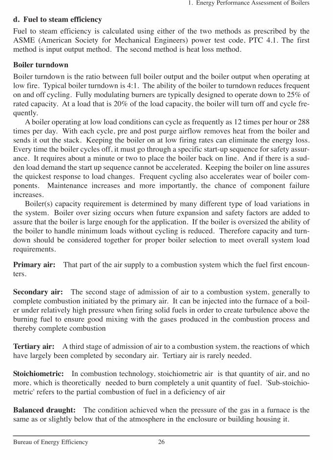
d. Fuel to steam efficiency
Fuel to steam efficiency is calculated using either of the two methods as prescribed by theASME (American Society for Mechanical Engineers) power test code, PTC 4.1. The firstmethod is input output method. The second method is heat loss method.
Boiler turndown
Boiler turndown is the ratio between full boiler output and the boiler output when operating atlow fire. Typical boiler turndown is 4:1. The ability of the boiler to turndown reduces frequenton and off cycling. Fully modulating burners are typically designed to operate down to 25% ofrated capacity. At a load that is 20% of the load capacity, the boiler will turn off and cycle fre-quently.
A boiler operating at low load conditions can cycle as frequently as 12 times per hour or 288times per day. With each cycle, pre and post purge airflow removes heat from the boiler andsends it out the stack. Keeping the boiler on at low firing rates can eliminate the energy loss.Every time the boiler cycles off, it must go through a specific start-up sequence for safety assur-ance. It requires about a minute or two to place the boiler back on line. And if there is a sud-den load demand the start up sequence cannot be accelerated. Keeping the boiler on line assuresthe quickest response to load changes. Frequent cycling also accelerates wear of boiler com-ponents. Maintenance increases and more importantly, the chance of component failureincreases.
Boiler(s) capacity requirement is determined by many different type of load variations inthe system. Boiler over sizing occurs when future expansion and safety factors are added toassure that the boiler is large enough for the application. If the boiler is oversized the ability ofthe boiler to handle minimum loads without cycling is reduced. Therefore capacity and turn-down should be considered together for proper boiler selection to meet overall system loadrequirements.
Primary air: That part of the air supply to a combustion system which the fuel first encoun-ters.
Secondary air: The second stage of admission of air to a combustion system, generally tocomplete combustion initiated by the primary air. It can be injected into the furnace of a boil-er under relatively high pressure when firing solid fuels in order to create turbulence above theburning fuel to ensure good mixing with the gases produced in the combustion process andthereby complete combustion
Tertiary air: A third stage of admission of air to a combustion system, the reactions of whichhave largely been completed by secondary air. Tertiary air is rarely needed.
Stoichiometric: In combustion technology, stoichiometric air is that quantity of air, and nomore, which is theoretically needed to burn completely a unit quantity of fuel. 'Sub-stoichio-metric' refers to the partial combustion of fuel in a deficiency of air
Balanced draught: The condition achieved when the pressure of the gas in a furnace is thesame as or slightly below that of the atmosphere in the enclosure or building housing it.
1. Energy Performance Assessment of Boilers
26Bureau of Energy Efficiency
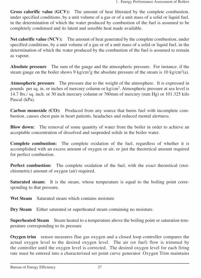
Gross calorific value (GCV): The amount of heat liberated by the complete combustion,under specified conditions, by a unit volume of a gas or of a unit mass of a solid or liquid fuel,in the determination of which the water produced by combustion of the fuel is assumed to becompletely condensed and its latent and sensible heat made available.
Net calorific value (NCV): The amount of heat generated by the complete combustion, underspecified conditions, by a unit volume of a gas or of a unit mass of a solid or liquid fuel, in thedetermination of which the water produced by the combustion of the fuel is assumed to remainas vapour.
Absolute pressure The sum of the gauge and the atmospheric pressure. For instance, if thesteam gauge on the boiler shows 9 kg/cm2g the absolute pressure of the steam is 10 kg/cm2(a).
Atmospheric pressure The pressure due to the weight of the atmosphere. It is expressed inpounds per sq. in. or inches of mercury column or kg/cm2. Atmospheric pressure at sea level is14.7 lbs./ sq. inch. or 30 inch mercury column or 760mm of mercury (mm Hg) or 101.325 kiloPascal (kPa).
Carbon monoxide (CO): Produced from any source that burns fuel with incomplete com-bustion, causes chest pain in heart patients, headaches and reduced mental alertness.
Blow down: The removal of some quantity of water from the boiler in order to achieve anacceptable concentration of dissolved and suspended solids in the boiler water.
Complete combustion: The complete oxidation of the fuel, regardless of whether it isaccomplished with an excess amount of oxygen or air, or just the theoretical amount requiredfor perfect combustion.
Perfect combustion: The complete oxidation of the fuel, with the exact theoretical (stoi-chiometric) amount of oxygen (air) required.
Saturated steam: It is the steam, whose temperature is equal to the boiling point corre-sponding to that pressure.
Wet Steam Saturated steam which contains moisture
Dry Steam Either saturated or superheated steam containing no moisture.
Superheated Steam Steam heated to a temperature above the boiling point or saturation tem-perature corresponding to its pressure
Oxygen trim sensor measures flue gas oxygen and a closed loop controller compares theactual oxygen level to the desired oxygen level. The air (or fuel) flow is trimmed bythe controller until the oxygen level is corrected. The desired oxygen level for each firingrate must be entered into a characterized set point curve generator. Oxygen Trim maintains
1. Energy Performance Assessment of Boilers
27Bureau of Energy Efficiency
the lowest possible burner excess air level from low to high fire. Burners that don't haveOxygen Trim must run with Extra Excess Air to allow safe operation during variations inweather, fuel, and linkage.
Heat transfer mediums
There are different types of heat transfer medium e.g. steam, hot water and thermal oil. Steamand Hot water are most common and it will be valuable to briefly examine these common heattransfer mediums and associated properties.
Thermic Fluid
Thermic Fluid is used as a heat transfer mechanism in some industrial process and heatingapplications. Thermic Fluid may be a vegetable or mineral based oil and the oil may be raisedto a high temperature without the need for any pressurization. The relatively high flow andreturn temperatures may limit the potential for flue gas heat recovery unless some other systemcan absorb this heat usefully. Careful design and selection is required to achieve best energyefficiency.
Hot water
Water is a fluid with medium density, high specific heat capacity, low viscosity and relativelylow thermal conductivity. At relatively low temperature e.g. 70°C � 90°C, hot water is usefulfor smaller heating installations.
Steam
When water is heated its temperature will rise. The heat added is called sensible heat and theheat content of the water is termed its enthalpy. The usual datum point used to calculateenthalpy is 0°C.
When the water reaches its boiling point, any further heat input will result in some propor-tion of the water changing from the liquid to the vapour state, i.e. changing to steam. The heatrequired for this change of state is termed the 'latent heat of evaporation' and is expressed interms of a fixed mass of water. Where no change in temperature occurs during the change ofstate, the steam will exist in equilibrium with the water. This equilibrium state is termed 'satu-ration conditions'. Saturation conditions can occur at any pressure, although at each pressurethere is only one discrete temperature at which saturation can occur.
If further heat is applied to the saturated steam the temperature will rise and the steam willbecome 'superheated'. Any increase in temperature above saturated conditions will be accom-panied by a further rise in enthalpy.
Steam is useful heat transfer medium because, as a gas, it is compressible. At high pressureand consequently density, steam can carry large quantities of heat with relatively small volume.
1. Energy Performance Assessment of Boilers
28Bureau of Energy Efficiency
1. Energy Performance Assessment of Boilers
29Bureau of Energy Efficiency
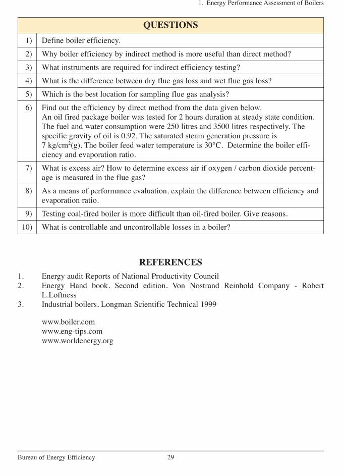
QUESTIONS
1) Define boiler efficiency.
2) Why boiler efficiency by indirect method is more useful than direct method?
3) What instruments are required for indirect efficiency testing?
4) What is the difference between dry flue gas loss and wet flue gas loss?
5) Which is the best location for sampling flue gas analysis?
6) Find out the efficiency by direct method from the data given below.An oil fired package boiler was tested for 2 hours duration at steady state condition.The fuel and water consumption were 250 litres and 3500 litres respectively. Thespecific gravity of oil is 0.92. The saturated steam generation pressure is7 kg/cm2(g). The boiler feed water temperature is 30°C. Determine the boiler effi-ciency and evaporation ratio.
7) What is excess air? How to determine excess air if oxygen / carbon dioxide percent-age is measured in the flue gas?
8) As a means of performance evaluation, explain the difference between efficiency andevaporation ratio.
9) Testing coal-fired boiler is more difficult than oil-fired boiler. Give reasons.
10) What is controllable and uncontrollable losses in a boiler?
REFERENCES 1. Energy audit Reports of National Productivity Council2. Energy Hand book, Second edition, Von Nostrand Reinhold Company - Robert
L.Loftness 3. Industrial boilers, Longman Scientific Technical 1999
www.boiler.comwww.eng-tips.comwww.worldenergy.org