asme bladder accumulator type : aa...an inert gas - nitrogen - is filled into the bladder through a...
TRANSCRIPT
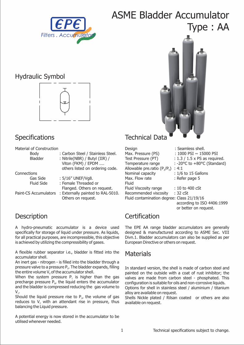
Specifications
Material of Construction Body : Carbon Steel / Stainless Steel. Bladder : Nitrile(NBR) / Butyl (IIR) / Viton (FKM) / EPDM .... others listed on ordering code.Connections Gas Side : 5/16” UNEF/Vg8. Fluid Side : Female Threaded or Flanged. Others on request.Paint-CS Accumulators : Externally painted to RAL-5010. Others on request.
Technical Data
Design : Seamless shell.Max. Pressure (PS) : 1000 PSI ~ 15000 PSITest Pressure (PT) : 1.3 / 1.5 x PS as required.Temperature range : -20°C to +80°C (Standard)Allowable pre.ratio (P /P ) : 4:12 0
Nominal capacity : 1/6 to 15 GallonsMax. Flow rate : Refer page 5FluidFluid Viscosity range : 10 to 400 cStRecommended viscosity : 32 cStFluid contamination degree: Class 21/19/16 according to ISO 4406:1999 or better on request.
Description
A hydro-pneumatic accumulator is a device used specifically for storage of liquid under pressure. As liquids, for all practical purposes, are incompressible, this objective is achieved by utilizing the compressibility of gases.
A flexible rubber separator i.e., bladder is fitted into the accumulator shell.An inert gas - nitrogen - is filled into the bladder through a pressure valve to a pressure P . The bladder expands, filling 0
the entire volume V of the accumulator shell.0
When the system pressure P is higher than the gas 1
precharge pressure P , the liquid enters the accumulator 0
and the bladder is compressed reducing the gas volume to V .1Should the liquid pressure rise to P , the volume of gas 2
reduces to V with an attendant rise in pressure, thus 2
balancing the Liquid pressure.
A potential energy is now stored in the accumulator to be utilised whenever needed.
Certification
The EPE AA range bladder accumulators are generally designed & manufactured according to ASME Sec. VIII Divn.1. Bladder accumulators can also be supplied as per European Directive or others on request.
Materials
In standard version, the shell is made of carbon steel and painted on the outside with a coat of rust inhibitor; the valves are made from carbon steel - phosphated. This configuration is suitable for oils and non-corrosive liquids.Options for shell in stainless steel / aluminium / titanium alloy are available on request.Shells Nickle plated / Rilsan coated or others are also available on request.
Hydraulic Symbol
1
ASME Bladder AccumulatorType : AA
Technical specifications subject to change.

Operation
Sequence of operations in the accumulator working cycle
A) General appearance in assembled condition.
B) Bladder occupying the entire space inside the shell after precharge.
C&D) The accumulator in working condition between minimum pressure (C) & maximum pressure (D) delivers fluid and calculated between V & V i.e., 1 2
∆V = V - V1 2.
Accumulator now has a potential energy to be utilised as
desired.
Construction
The EPE bladder accumulator, generally designed & manufactured according to European directive, comprises a steel shell in which is fitted a bladder complete with a gas valve and a fluid port with the poppet valve (Fig.2)
The accumulator shell is a pressure vessel forged or fabricated from high grade steel designed and manufactured to meet relevant international standards. For special applications various surface coatings are available as well as stainless steel construction.
The bladder construction which is unique to EPE is moulded in a single piece thus obviating problems associated with seamed construction. The gas valve is fitted in such a manner which allows it to be connected and easily and safely. In addition the valve, not an integral part of the bladder, can be re-used, thus reducing maintenance costs.
Bladders are normally manufactured from nitrile, but for special applications butyl, neoprene, ethylene-propylene etc, are available.
The gas valve is connected to the bladder by a rubber coated washer to ensure a gas tight joint and a non return valve is incorporated for bladder inflation. The bladder, complete with the gas valve is attached to the accumulator shell by a lock nut, and the assembly is protected by a cover.
The fluid port contains a poppet valve to prevent bladder from extruding out of the fluid port while allowing fluid to flow.
Fig.2
Gas Valve
Accumulator Shell
Bladder
Poppet Valve
Bleed
Fluid Port
P . V P . V P . V0 0 1 1 2 2
Fig.1
A B C D
General
2

Ordering Code - Accumulators - ASME Range
6
BSPP (Parallel Thread)BSPT (Taper Thread)NPT (Taper Thread)
To suit SAE 3000 PSI flange To suit SAE 6000 PSI flange
Square FlangeSAE Internal Thread
MetricUNI-DIN Flange
ANSI FlangeAdaptor (for use with type G connection)
Fluid Port Connection
type
= G (standard)= T= N= 3= 6= Q= S= M= D= A= R# {# = G/T/N/S/M}
1 Series = AAASME Design Accumulators
2Nominal
Capacity (Gal)
= 0.6= 1= 4= 10= 20= 37= 57
1/6 Gallon1/4 Gallon
1 Gallon2.5 Gallons
5 Gallons 10 Gallons 15 Gallons
3Bladder & Seal
material
Nitrile ButylVitonEPDM
Hydrogeneted NitrileNeoprene
Nitrile for HydrocarbonsLow Temp. Nitrile
Epichlorohydrin
= P (standard)= B= V= E= K= N= H= F= Y
5 Shell material
Carbon SteelNickel Coated Carbon Steel
Stainless SteelRilsan Coated Carbon Steel
= C (standard)= N= X= V
4
1000 PSI2000 PSI3000 PSI4000 PSI5000 PSI
10000 PSI15000 PSI
* Other pressures available in request
= 1000= 2000= 3000= 4000= 5000= 10000= 15000
Max. WorkingPressure (PSI)
3
* Before ordering, check for availability
1 2 3 4 5 10 12 13 1411
AA P 3000 C 7W C10 –C 4
9
To indicate only if applicable
/ PO:100 / -
6 7 8
G 09 F

4
Ordering Code - Accumulators
* Before ordering, check for availability
7
for G T N 3 6 Q R
1/8”1/4”3/8”1/2”3/4”1”
1-1/4”1-1/2”
2” Multi Ports (R)
(Ref. other variants)
= 01= 02= 03= 04= 05= 06= 07= 08= 09= zz
for S 1-1/16”-121-5/8”-121-7/8”-12
= 21= 22= 23
for M M14x1.5M16x1.5M18x1.5M22x1.5M27x2.0M32x1.5M33x1.5M40x1.5M42x1.5M45x1.5M50x1.5
= 31= 32= 33= 34= 35= 36= 37= 38= 39= 40= 41
for D DN20/40DN20/250DN25/16DN25/40DN25/250DN32/40DN32/250DN40/40DN40/250 DN50/16DN50/40DN50/64DN50/250DN65/16DN65/40DN80/16DN100/16DN100/40
= 51= 52= 53= 54= 55= 56= 57= 58= 59= 60= 61= 62= 63= 64= 65= 66= 67= 68
for A 3/4” /3003/4” /15001” /3001” /15001-1/4” /3001-1/4” /15001-1/2” /3001-1/2” /15002” /1502” /3002” /4002” /1500
= 81= 82= 83= 84= 85= 86= 87= 88= 89= 90= 91= 92
Fluid Port Connection
size
8
Female ThreadMale Thread
For SAE FlangeFlange
Socket Weld Nipple
= F = M= S= L= SW
Fluid Port Connection
design
for A WN-RFWN-RTJSO-RFSW-RFSW-RTJ
= WN= WJ= SO= SW= SJ
1 2 3 4 5 10 12 13 1411
AA P 3000 C 7W C10 –C 4
9
To indicate only if applicable
/ PO:100 / -
6 7 8
G 09 F
10Fluid Valve
material
Carbon steelNickel Coated carbon steel
Stainless SteelZn-Ni Coated Carbon Steel
= C (standard)= N= X= Z
11Gas Valve
material
Carbon steelNickel Coated carbon steel
Stainless SteelZn-Ni Coated Carbon Steel
= C (standard)= N= X= Z
9 CertificationASME Sec.VIII Divn.1 App.22 (w/o stamp)
ASME Sec.VIII Divn.1 App.22 - U stamp = 7W (standard)= 7U
12Gas Fill Valve connection
5/16” UNEF (integral in 7/8 UNF Gas Valve)Without Gas Fill Valve
5/8” UNF 5/8” UNF in Stainless Steel
5/16” UNEF/Vg81/4” BSP
Double Lock Military Valve
= 4 (standard)= 0= V = X= 1= 2= 8

= -= XX13
Precharge Pressure
Uncharged ConditionPrecharge Pressure in PSIG
Ordering Code - Accumulators
1 2 3 4 5 10 12 13 1411
AA P 3000 C 7W C10 –C 4
9
To indicate only if applicable
/ PO:100 / -
6 7 8
G 09 F
* Before ordering, check for availability
14
Standard Accumulator - Without any variants
Liquid Side VariantsLiquid Adapter in SS (if different from FPA)
Poppet & spring in SS (if different from FPA)Fluid Port Assembly without Bleed Port
3-Way adaptor - 1/2” BSPF x 1/4” BSPF3-Way adaptor - 1/2” BSPF x 3/8” BSPF3-Way adaptor - 1/2” BSPF x 1/2” BSPF3-Way adaptor - 3/4” BSPF x 1/4” BSPF3-Way adaptor - 3/4” BSPF x 3/8” BSPF
3-Way adaptor - 1” BSPF x 1/4” BSPF
Gas Side VariantsProtection cap in SS (if different from GVA)
Protection cap with Plastic InsertName plate in Brass
Name Plate in SSLifting Hook
Adapter for connecting ¼” Gauge (without gauge)Adapter with xxx PSI 63mm Pressure Gauge
Adapter with xxx PSI rupture disc Adapter with xxx PSI rupture disc + 1/4” BSPF Port
Adapter with xxx PSI rupture disc + yyy PSI 63mm GaugeAdapter with xxx PSI rupture disc + 1/4” NPTF Port Adapter with xxx PSI rupture disc + 3/8” NPTF Port Adapter with xxx PSI rupture disc + 1/2” NPTF Port Adapter with VS214 Gas Safety Valve set at xxx PSI
Adapter with 1/4” BSP Needle ValveAdapter with 1/4” BSP Needle Valve in SS
Adapter with PGSV (Pressure Gauge Shut-off Valve)Adapter with PGSV + xxx PSI 63mm pressure gauge
External VariantsFinish Paint - RAL-5003
Internal VariantsFlushing to NAS-10Flushing to NAS-9Flushing to NAS-8Flushing to NAS-7Flushing to NAS-6Flushing to NAS-5
Othervariants
= --
= L01= L02= L03= L11= L12= L13= L14= L15= L16
= G01= G02= G03= G04= G06= G11= G12(xxx)= G13(xxx)= G14(xxx)= G15(xxx/yyy)= G16(xxx)= G17(xxx)= G18(xxx)= G19(xxx)= G21= G22= G23= G24(xxx)
= E01
= F10= F09= F08= F07= F06= F05
Max. Flow Rates (l/min)
QP
0.6Type \ Size
AA
1 4 10 20
300 300 600
57
1000 10001000
37
1000
5

Dimensions & Spare Parts List - AA (Poppet design)
* Other pressures and capacities available on request
1/61/41
2.5510151/61/41
2.551015
3.1514
36.558921303.15144065105
153.5
AA-0.6AA-1AA-4AA-10AA-20AA-37AA-57AA-0.6AA-1AA-4AA-10AA-20AA-37AA-57
3000
4000
PSIPre.Max.
Model A øDC øF IB øE H A/F1 A/F2kgsGal RGWt.Vol.DryGas Fluid Port Connection (BSP)
2802904005708801400199028029040057088014001990
474747
60
474747
60
525265
101
525265
101
89114168
223
89114168
232
252525
25
252525
25
363653
77
363653
77
111111
11
111111
11
140140140
140
140140140
140
323232
32
323232
32
323250
70
323250
70
3/4”3/4”
1-1/4”
2”
3/4”3/4”
1-1/4”
2”
3/8”3/8”
3/8” - 1/2” - 3/4”
1/2” - 3/4” - 1”1-1/4” - 1-1/2”
3/8”3/8”
3/8” - 1/2” - 3/4”
1/2” - 3/4” - 1”1-1/4” - 1-1/2”
6
AA AA
Fig.4Fig.3
Accumulator ShellBladderGas Valve BodyRubber-coated WasherGas Valve Lock NutProtection CapName PlateRetaining Ring“O” RingSupporting RingSpacer RingFluid Port Ring NutBleed ScrewSeal RingFluid Port BodyPoppetSpringBrake BushingSelf-Locking NutAdaptor O-Ring
11111111111111111111
1
1
1
1234567891011121314151617181920
Item# Description Qty. AA-0.6 AA-1 AA-4 AA-10 AA-20 AA-37 AA-57
--
B10106C10106110240110241G10304I10127I56022K10133L10120M1012205XXXXC13384N10115O10111P10112Q10113803XXX097009
V12044
H12024
R12030
--
B10203C10205110240110241G10305I10222211030K10227L10223M1021705XXXXC13384N10144O10221P10149Q10226S10228161013
V12046
H12044
R12050
--
B10337NI0023110240110241G10306I10317237032K10320L10319M10321BBXXXXC39XXXN10311O10310P10322Q10314S10341212013
V12071
H12064
R12080
--
B10106C10106110240110241G10304I10123I56022K10133L10120M1012205XXXXC13384N10115O10111P10112Q10113S10114097013
V12044
H12023
R12030
Gas Valve Assembly- consists item # 3 to 6Fluid Port Assembly- consists item # 8 to 19Gasket Set- consists item # 8,9,10,14
--
B10337Ni0023110240110241G10306I10317237032K10320L10319M10321BBXXXXC39XXXN10311O10310P10322Q10314S10341212013
V12071
H12064
R12080
--
B10337Ni0023110240110241G10306I10317237032K10320L10319M10321BBXXXXC39XXXN10311O10310P10322Q10314S10341212013
V12071
H12064
R12080
--
B10337Ni0023110240110241G10306I10317237032K10320L10319M10321BBXXXXC39XXXN10311O10310P10322Q10314S10341212013
V12071
H12064
R12080
5/16” UNEF
2
3
4
56
7
89101112131415
16
17
18
19
20
21
1

7
Ordering Code - Bladder Assembly
1 2 3 4 5 6
- - - - - SA CP U7/8V10 4
1 Design = SA (standard)Standard
3Bladder & Seal
material
Nitrile (NBR)Butyl (IIR)
Viton (FKM)Ehtylene-Propylene (EPDM)
Hydrogenated Nitrile (HNBR)Neoprene (CR)
Nitrile for HydrocarbonsLow Temp. Nitrile
Epichlorohydrin (ECO)For foods
= P (standard)= B= V= E= K= N= H= F= Y= A
4Gas Valve
type
Without Gas Valve (only bladder)7/8” UNF(M) with Integral 5/16” UNEF/Vg8 fill valve
7/8” UNF(M) with screw-in Gas Fill ValveM22x1.5(M) with screw-in Gas Fill Valve
= 0= U7/8V (Std)= U7/8= M22
5Gas Valve
material
Carbon steelNickel Coated carbon steel
Stainless SteelZn-Ni Coated Carbon Steel
= C (standard)= N= X= Z
6Gas Fill Valve connection
5/16” UNEF (integral in 7/8 UNF Gas Valve)Without Gas Fill Valve
Others - As per page 4
= 4 (standard)= 0= x (ref page 4)
2Nominal
Capacity (Gal)= 0.6 ~ 571/6 Gal to 15 Gal - As per page 3
* Before ordering, check for availability
Bladder dimensions
SA-0.6SA-1SA-4SA-10SA-20SA-37SA-57
ModelØDmm
WeightKgs
Lmm
7495145
198
12013119830558011051538
0.060.130.390.921.753.304.60
ØD
L
M22x1.5
Screw-in Gas Fill Valve
Fig.5
Fig.6
Valve design
7/8” UNF
Screw-in Gas Fill Valve
7/8” UNF
5/16” UNEF/Vg8 - Integral
Type : M22 Type : U7/8 Type : U7/8V

The choice of the elastomer used for the bladder depends on the liquid to be used and on the operating temperatures (and at times, storage). In the chart below, each polymer has a designated letter to be used in the ordering code.
Codeletter
E
Polymer ISO
EPDM
Temperaturerange (°C)
-20 +90to
Some of the liquids compatible with the polymer
N CR -20 +85to
V FKM -20 +121to
Break fluids, hot water, leaching fluids, detergents, water-glycol (HFC), many acids and bases, saline solutions, skydrol 500, etc.
Freon (12-21-22-113-114-115), water and aqueous solutions, ammonia, carbon dioxide, mineral, paraffin and silicon oils.
The same as with standard nitrile but with excellent performance at both high and low temperatures.
P NBR -20 +85to
F NBR -40 +70to
H NBR -10 +90to
Mineral, vegetable, silicon and lubricating oils, industrial water, glycols, non-flammable liquids (HFA-HFB-HFC), aliphatic hydrocarbons, butane, diesel oil, kerosene, fuel oils etc.
The same as with standard nitrile + a number of different types of Freon. (This contains less acrylonitrile than the standard and is therefore more suitable for low temperatures, but is chemical resistance is slightly lower.
The same as with standard nitrile + regular and premium grade slightly aromatic gasoline.
K HNBR -50 +130to
A NBR -20 +85to
B IIR -20 +90to
The same as with standard nitrile but with excellent performance at both high and low temperatures.
Foods (specify which type when ordering).
Phosphoric esters (HFD-R), phosphate esters, fyrquel, hot water, ammonia, caustic soda, some kinds of Freon (22-31-502), glycol-based brake fluids, some acids, alcohols, ketones, esters, skydrol 7000, etc.
Y ECO -30 +1 0to 0 Lead-free gasoline, mineral oils.
Nitrile (Buna-N / Perbunan)
Ethylene-Propylene
Low TemperatureNitrile
For food-stuffs
Butyl
Nittrile for Hydrocarbons
Chloroprene(Neoprene)
Epichloridrin
Viton(Flouroelastomer)
Hydrogenated Nitrile
The precharge pressure P - In most cases the values 0
recomended in Gas Precharge Pressure - page-3 are valid although, as the pressure and, above all, the velocity of the yield required increase, there is the danger that in each cycle the bladder will knock against the poppet valve. In these cases it is possible to use P = 0.8 to 0.7 P .0 1
The P /P ratio - Any increase in this, will increase the 2 0
stress the bladder is subjected to in each cycle.
The maximum operating pressure P - Any increase in 2
this will subject the bladder to greater stress.
Flow rate - Flow rate does not affect bladder working life if values given in Table.2 are not exceeded. When approaching the maximum values, make sure there remains a residual volume of liquid > 10% of the volume V 0in the accumulator, in both loading & unloading conditions.
The frequency or number of cycles per day.
Installation - The vertical position with gas valve on top is the recommended arrangement. When the position is horizontal the bladder tends to rest and rub against the accumulator body. This could result in quicker wear.
The operating temperature - This is one of the factors which most affects the life of the bladder: at very low temperatures the bladder tends to become brittle; as the temperature rises, reaching, or going beyond the limits for the elastomer, the stress the bladder is subjected to increases exponentially, which can lead to fracturing within a short time.
It should be remembered that the temperature in the accumulator is in many cases higher than the one of the system, and that it rises with each increase of P , of P /P , 2 2 1
and with the volume of the accumulator (in other words, larger the accumulator, lesser is the capacity to dissipate heat).
Durability of the BladdersIt is essential, in order to make the correct choice, to take into consideration the working conditions that the bladder will be operating in, because these can considerably affect the durability of the bladder. Assuming that the liquid used is clean and compatible with the bladder material, there are a number of factors which can affect the life of the bladder:
Material
Bladder - Material | Durability
* Check availability before ordering.
8

General
All EPE accumulators are carefully inspected and tested at the factory and are exactly as designated by the code printed on the name plate.In addition the name plate carries the accumulators serial number and if specified on order, the value on precharge.
On the accumulator shell are also marked :Manufacturer's serial number & date shell manufactured; identification mark; design standard applicable; maximum recommended working pressure; temperature range; capacity in liters.Accumulators are normally supplied empty (uncharged).Charged units can be supplied on request.ATTENTION: The max working pressure marked on the
accumulator must be ≥ that the calibrated pressure of the
relief valve.Before undertaking any work (repairs, replacement etc.) on the hydraulic circuit for mounting an accumulator, it is advisable to release completely the liquid pressure.Test certificates if required are supplied with the accumulator, or forwarded by mail.
Installation
To achieve a high degree of efficiency, the accumulator should be fitted as close as possible to the installation it serves.The space necessary for testing and filling equipment is at least 150mm above the gas-fill valve.
POSITION is possible from vertical one (gas valve on top) to the horizontal one.The manufacturers name plate stating initial pressure must remain visible.Access to vent screw must be kept unobstructed.MOUNTING by means of clamps, brackets and rubber support rings.
The mounting must be such that should a rupture occur on the pipe system at the liquid connection, or should the gas-fill valve break, the accumulator cannot be pulled from its mounting by the forces involved.
No welding or other mechanical process must be carried out on the accumulator shell for the purpose of attaching fastenings.
CONNECTION adopters and flanges are available on request. When fitting screws, reducers or the safety and shut-off block, care must be taken that the accumulator is held firmly by means of a spanner at the liquid valve, so that the liquid valve is not turned independently of the accumulator body.
To guarantee trouble free operation, the following points should be observed: A non-return valve to be fitted between pump and
accumulator to prevent reversal. The installation relief valve must be fitted directly to
the accumulator, after the non-return valve, and calibrated lower than the working pressure marked on the accumulator shell.
A shut-off valve and a dump valve are recommended to enable periodic checks or removals during normal operation. EPE safety blocks type B incorporate all the essential functions.
Preliminary Checking
Upon receipt check:That there has been no damage in transit.The identification code is as ordered.Before installation it is most important to ensure that the gas pressure corresponds to the desired value.The initial gas pressure must be selected to meet the service requirement.In general the design values are as follows:P0 = 0.9 P1, ( energy reserve, line shock absorber, etc.)P0 = 0.6 - 0.7 P1 ( pulsation damper )Gas precharge pressure is of crucial importance to the correct functions of the accumulator and the durability of the bladder.The gas pressure, when the accumulator is supplied pre-charged is related to the temperature of 20°C.In the case of accumulators supplied without pre-loading pressure, or after repair work it is necessary to perform inflation with nitrogen; must also be performed also the verification of the system by using the equipment type-PC following procedure checking & charging - page-10.
Operation & Maintenance
Clamp
SupportingRing
Bracket
9
Fig.7

Initial Operation
Before the system is pressurised it has to be bled. For this, the vent screw in the fluid port assembly has to be eased until fluid emerges.Then retighten the gas valve locknut carefully.The system is charged with maximum pressure and sealings and connections should be checked.
Periodic Checking
After the installation of a new unit, or following repairs, the initial pressure must be tested as follows:Atleast once during the first week so that any gas losses can be immediately observed and remedied.If no gas losses are observed during the first check, a second check should be carried out approximately 3 months later,If during this check no gas losses are evident, a six-month check should be sufficient.It is however recommend that heavy duty applications be checked every month.
Checking & Charging
Pre-Loading & Checking Set type-PC (refer Fig.8) is to be used for checking / charging of Bladder Accumulators. When charging, the nitrogen bottles must be capable of delivering pressure higher than the desired accumulator gas pressure.Use dry industrial nitrogen. NEVER USE OXYGEN OR AIR.Proceed as follows: Fit the suitable pre-charging equipment to the gas
valve; Connect it to the nitrogen cylinder with the charging
hose; Slowly introduce nitrogen into the accumulator until
reaching a pressure slightly above the required level; Close the valve of nitrogen cylinder and disconnect the
charging hose from the equipment; Wait for the gas temperature stabilization; Set the pressure by venting off the excess of gas.
It is important that the gas pressure be kept constant and should therefore be checked periodically by means of the filling and checking equipment PC/...The same equipment is used for re-inflating the bladder after repair work or change of use.Connection is made by the special hose to the dry nitrogen bottle.
ONLY NITROGEN MUST BE USED. AIR OR OXYGEN COULD CAUSE AN EXPLOSION.
Pressure Checks
This is simple operation, the correct procedure is as follows: Isolate the accumulator from the system and reduce
the liquid pressure to zero. Remove the protective and sealing caps from the gas
valve. Prior to the mounting PC/ - equipment ensure that the
valve A is unscrewed, that bleed valve B is closed and that is non-return valve C is screwed tight. (refer Fig.9)
Attach the unit to the gas-fill valve by means of the knurled nut D.
Screw valve A to a point where pressure is registered.If the pressure is OK remove the PC/unit as follows: Unscrew the valve A. Open the bleed valve B and unscrew the nut D.
Pressure Reduction
If the pressure has to be reduced this is done by opening the bleed valve B slowly until the correct pressure is registered on the gauge.
Operation & Maintenance
Bleed
Ring Nut
Non-Return ValveConnection forCharging Hose
Pin
U7/8V type Valve
125
10
Fig.8 Fig.9

Increase or reset precharge pressure
If it is necessary to fill, or to increase the gas pressure, proceed as follows: Fit the PC/ unit as described above. Fit the connection to nitrogen cylinder. (refer Fig.9 &
Fig.10) Connect the hose between the cylinder and the non-
return valve C. Slowly open the valve on the cylinder till the gauge
registers a pressure slightly higher than the one desired, then shut.
Unscrew A and reduce the pressure PC/ unit to zero by means of the bleed valve B.
Disconnect the hose from the non-return valve C. and replace cap.
Close the bleed valve and wait approximately 5 mins. for the temperature to adjust.
Screw valve A until the pressure can be read. This should be slightly higher than the desired pressure.
Adjust by means of bleed valve, remove the filling unit. Use soapy water test for leaks. Replace the valve cover and protection cap.
The accumulator is ready for use.
Standard equipment PC-280/70 is supplied with two pressure gauges: the high pressure gauge (0-280 bar) is used for pre-loading values higher than 50 bar and low pressure gauge (0-70 bar) for values lower than 50 bar.
Operation & Maintenance
A PRESSURE REDUCING VALVE MUST BE INSTALLED BETWEEN THE NITROGEN GAS CYLINDER AND THE ACCUMULATOR WHEN THE GAS CYLINDER PRESSURE IS HIGHER THAN MAX PERMISSIBLE PRESSURE OF ACCUMULATOR.
11
Fig.10
Tightening Torque Values (Nm)
0.6
Fluid Port Ring NutBleed ScrewGas Valve Lock NutGas Fill ValveValve Insert
1 4Component \ Size 20 57
440 + 6030 + 10140 + 4030 + 5
0.3 + 0.2
37
440 + 6030 + 10140 + 4030 + 5
0.3 + 0.2
440 + 6030 + 10140 + 4030 + 5
0.3 + 0.2
10
440 + 6030 + 10140 + 4030 + 5
0.3 + 0.2
200 + 205 + 1
80 + 2030 + 5
0.3 + 0.2
90 + 15 5 + 1
80 + 2030 + 5
0.3 + 0.2
90 + 15 5 + 1
80 + 2030 + 5
0.3 + 0.2

General
If the Accumulator has to be stripped for any reason, the following procedure must be followed in the sequence shown below.
Before removing Accumulators for servicing, the fluid pressure must be reduced to zero by exhausting the fluid through the system and back to the reservoir.
When this is not possible the Accumulator shut-off valve must be closed and the dump valve opened to exhaust the Accumulator directly to the reservoir.
Dismantling the Accumulator
Isolate from the liquid connection and drain. Place the Accumulator in a vice horizontally. Remove the protection caps. Discharge gas from the bladder by means of pre-loading
& checking device. (Fig. D-1). Dismantle the gas-fill valve.Only at this point can the liquid connection be dismantled.
Remove the bleed screw. (Fig. D-2) Remove the ring nut and the spacer ring. (Fig. D-3) Push the fluid port body into the vessel and remove the
gasket and 'O'Ring. (Fig. D-4) Remove by bending the rubber coated retaining ring.
(Fig. D-5) Remove the fluid port body. (Fig. D-6) Remove the nut holding the gas valve and nameplate.
(Fig. D-7) Remove the bladder from the liquid side by slightly
twisting. (Fig. D-8)
Cleaning and inspection
Carefully clean all components including the bladder and the inside of the Accumulator body.
Mainly check that: THE BLADDER is not damaged, worn or perished. THE POPPET VALVE in High Pressure Range (types - AS /
ASHF / ASWP) slides freely and that the spring is undamaged.
GASKETS AND SEALS are not worn. THE INTERIOR of Accumulator body has no cracks or
signs of failure. THE ANTI EXTRUSION plate in Low Pressure Range
(type-ASWD) is not damaged or worn.
REPLACE ALL SUSPECT AND WORN PARTS. THE BLADDER CAN'T BE REPAIRED.
Operation & Maintenance
WARNING : Before any work is undertaken the gas pressure must be fully relieved.
12
D-1 D-2
D-3 D-4
D-5 D-6
D-7 D-8

Bladder Gas Valve Assembly
Should the bladder have to be replaced and the gas valve is in good condition it is possible to fit a new bladder to the old gas valve (or vice-versa) taking care to ensure that the edge of the mouth piece makes a perfect fit with the valve seat. The valve is then put into place, by means of hand pressure on the rubber coated washer until it is no longer possible to remove unless force is used. The bladder can now be inserted into the Accumulator.
Assembling the Accumulator
Ensure that all components are in good condition and perfectly clean. Assemble in the following order:
Insert the bladder (use a threaded tube M 12 x 1.5). (Fig. A-1)
Mount name plate and nut for the gas valve body. (Fig. A-2)
Tighten the nut holding the gas valve body with a spanner. (Fig. A-3)
Insert the fluid port assembly and the rubber coated retaining ring. (Fig. A-4)
Locate the fluid port on to the support ring, fit gaskets and spacer ring. (Fig. A-5)
Tighten the ring nut making sure the assembly is centrally located. (Fig. A-6)
Fit the bleed screw and gasket. Pour a small amount of liquid into the accumulator to lubricate. (Fig. A-7)
Finally mount the gas-fill valve, charge accordingly to checking & charging - page-10 and again tighten the gas valve nut.
Operation & Maintenance
13
Fig.11
A-1 A-2
A-3 A-4
A-5 A-6
A-7

EPE Process Filters & Accumulators Pvt. Ltd., Techni Towers, C-54/A, A.P.I.E, Balanagar, Hyderabad - 500 037, Telangana, INDIAPh : +91 40 23778803 | Fax : +91 40 23871447 | [email protected] | www.epe-india.com 14
Certification
All hydraulic accumulators are pressure vessels and are subject to the national regulations and directives, valid at the place of installation.
Bladder accumulators type AA are generally designed and manufactured according to ASME Sec.VIII Divn.1.
Safety
All pressure vessels must be protected by means of a pressure relief valve. Safety Blocks are used for this purpose.
The most important elements of the safety-related equipment are the pressure measuring device (pressure gauge), device for the preventing excess pressure (safety valves), non-return valves and shut-off valves and devices for de-pressurising (bleed valves). These functions can be performed with individual components or integrated in the form of a safety block .
Special Instructions
It is strictly forbidden to:- weld or solder or carry out any mechanical operations on the accumulator.- engrave or permanently stamp the surfaces of the accumulator shell and / or carry out other operations that could affect or change the mechanical properties of the accumulator- use the accumulator as a structural element: it should not be subjected to stresses or loads.- change the data of the nameplate and / or accumulator without the permission of the manufacturer.- use a different fluid than those designed for.
Installation
Before installation, you must perform a visual check to verify that the accumulator has not suffered any damage during shipping / handling. Verify that the requested type matches with what stamped on the nameplate.
We recommend using the accumulator with a suitable safety valve or a security safety block. This device provides user and equipment protection against possible damage caused by pressure surges, and also makes the maintenance of the accumulator easier, so facilitating the interception and the discharge.
Provide for a clearance of 200 mm above the gas pre-charge valve to allow access to and control of the pre-charge equipment.
These accumulators may be installed in any position from horizontal to vertical (preferably with the pre-charge valve at the top), and the identification details must be visible.
Proceed to the assembly so that no abnormal force affects the pipes connected directly or indirectly to the accumulator, so we recommend the use of supporting components and also fastening to avoid the transmission of vibrations.
Make sure the fluid is compatible with the elastomer of the bladder.
Check that the max. allowed accumulator pressure is equal to or greater than that of the hydraulic circuit and that the temperature during operation is maintained within the range expected.
Make sure the fluid does not contain contaminants and/or abrasive.
Disposal
Before the accumulator is sent for disposal or recycling, it should always be discharged completely of the pre-charge pressure and the gas valve unscrewed. Pre-loading and checking kits are suited for this task.
Environmental Protection
Careless disposal of the accumulator and the residual fluid contained therein can cause environmental pollution.
Dispose the Accumulator in accordance with provisions applicable in the country of use.
Fluid residues are to be disposed according to the respective safety data sheets valid for the specific hydraulic fluids.
Special Instructions
EPE/1
1.0
02/A
A R
ev.
1/0
3-2
017