bladder accumulators - phtruck.com hy10-1630/us bladder accumulators introduction 66 parker hannifin...
TRANSCRIPT

65 Parker Hannifin CorporationHydraulic Accumulator DivisionRockford, Illinois USA
Bladder Accumulators• Bottom Repairable• Top Repairable• Medium Flow• High Flow• Transfer Barrier• Gas Bottle
Features:• Operating Pressures to 6600 PSI
• Ten Different Capacities from10 cu in to 15 gallons
• Nine Different Configurations
• Highest Quality In-HouseManufactured Bladders
• ASME Certification Standard,1 Gallon & Up
• Water/Chemical Service Available,with Stainless Steel Ports
• Six Bladder Compounds to Suit aVariety of Fluids & Temperatures
• CE Marking Available
BLADDER PRODUCTS

Catalog HY10-1630/US Bladder AccumulatorsIntroduction
66 Parker Hannifin CorporationHydraulic Accumulator DivisionRockford, Illinois USA
Bladder accumulators provide a means of regulating theperformance of a hydraulic system. They are suitable forstoring energy under pressure, absorbing hydraulic shocks,and dampening pump pulsation and flow fluctuations. Bladderaccumulators provide excellent gas and fluid separationensuring dependable performance, maximum efficiency, andlong service life.
Why Use Bladder Accumulators?• improves system efficiency• supplements pump flow• supplies power in emergency
• compensates for leakage• absorbs hydraulic shocks• very contaminant tolerant
• universal application• high/low temperature tolerance• safety, can't disassemble under pressure
• very quick response• works well with water, low lubricity fluids• wide range of compounds for a variety of fluids
Bladder Products…The Original and still the Best!The Greer bladder style accumulator is the industry's original,and still the best! For years this style of accumulator hasserved both the industrial and mobile hydraulic markets,providing a proven design for many hydraulic systemapplications.
The Greer bladder product line offers the broadest line ofquality products, including:
• 3000 & 5000 PSI Bottom Repairable• 3000 & 5000 PSI Top Repairable• 3000 PSI Medium Flow• 3000 PSI High Flow• 3000 PSI Transfer Barrier• 3000 & 5000 PSI Gas Bottles• A Wide Array of Options and Accessories
Greer bladder products maintain the highest quality becauseof our in-house bladder molding operations. The heart of thebladder accumulator is the actual bladder, and all Greerbladders are engineered and manufactured in our own facilityand subjected to our own high quality inspection standards.For your convenience, the latest in accumulator sizingtechnology is available with the inPHorm Accumulator Sizingand Selection Software.
SpecificationsMaterials• Shell – high strength alloy steel (SA372, all sizes comply
with ASME material specifications, 1 gal. & larger suppliedwith ASME Certification as standard)
• Ports – all oil service ports, high strength alloy steel– water & chemical service:
3000 psi, 304 stainless steel5000 psi, 17-4 PH stainless steel
• Poppet & Spring – 304 stainless steel• Gas Valve Cartridge – stainless steel• Gas Valve Protector – steel• Gas Valve Stem – steel• Bladders – various polymers, see Standard and Optional
Bladders.
Maximum Flow Rates
Pressure Ratings – 3000 and 5000 psi bladder accumulatorsare rated at minimum 4 to 1 design factors as standard. 4000and 6600 psi (ASME Appendix 22) bladder accumulators areavailable as an option at minimum 3 to 1 design factors. Forpressures over 6600 psi, consult the factory.
Max. Recommended Compression Ratio (max. workingpressure/precharge pressure): 4 to 1.
Max. Recommended Flow Size for Standard Mineral Oils
(gallon) GPM LPM10 cu in 23 87
1 pt & 1 qt 40 151150 cu in 60 227
1 150 5682½ thru 15 220 833
2½ thru 15, Medium Flow 480 18192½ thru 15, High Flow 600 2271
Fluids – Greer bladder accumulators are compatible with awide variety of fluids. The standard accumulator may be usedwith petroleum-based industrial or water-based flame resistantfluids. Bladders compatible with most industrial fluids can befurnished on special orders with temperature ranges from-40°F to 250°F (-40°C to 121°C).
Precharge – Units are shipped with a nominal nitrogenprecharge as standard. For specific precharge pressures,specify at the time of order.
Available Options – a wide variety of options are available onGreer bladder accumulators including:• Bladder Compounds (see Standard and Optional
Bladders in this section).• Ports (see Options in this section)• Port Adapters (see Accumulator Accessories)• Water & Chemical Service (see Options in this section)• Gas Valves (see Options in this section)• Fuse Plugs Assemblies (see Options in this section)• Fixed Gauge Adapters (see Accumulator Accessories)
IntroductionSpecifications
Certifications – ASME Certification (Section VIII-Div. 1) isavailable as standard on bladder accumulators (1 gallon & up)and ASME Appendix 22 Certification as an option. See page 3for a complete certification summary.
Std. ASME Cert. ASME Appendix 22
Size Status Rating D.F.* Rating D.F.*10 thru 150 in3 Consult
3000 PSI Option 3000 PSI 4 to 1 Factory1 thru 15 gal.
3000 PSI Std. 3000 PSI 4 to 1 4000 PSI 3 to 11 thru 15 gal.
5000 PSI Std. 5000 PSI 4 to 1 6600 PSI 3 to 1
*Note: D.F. = Design Factor.
Catalog HY10-1630/UStontent Bladder AccumulatorsIntroduction
67 Parker Hannifin CorporationHydraulic Accumulator DivisionRockford, Illinois USA
7
3
7
1
2
5
4
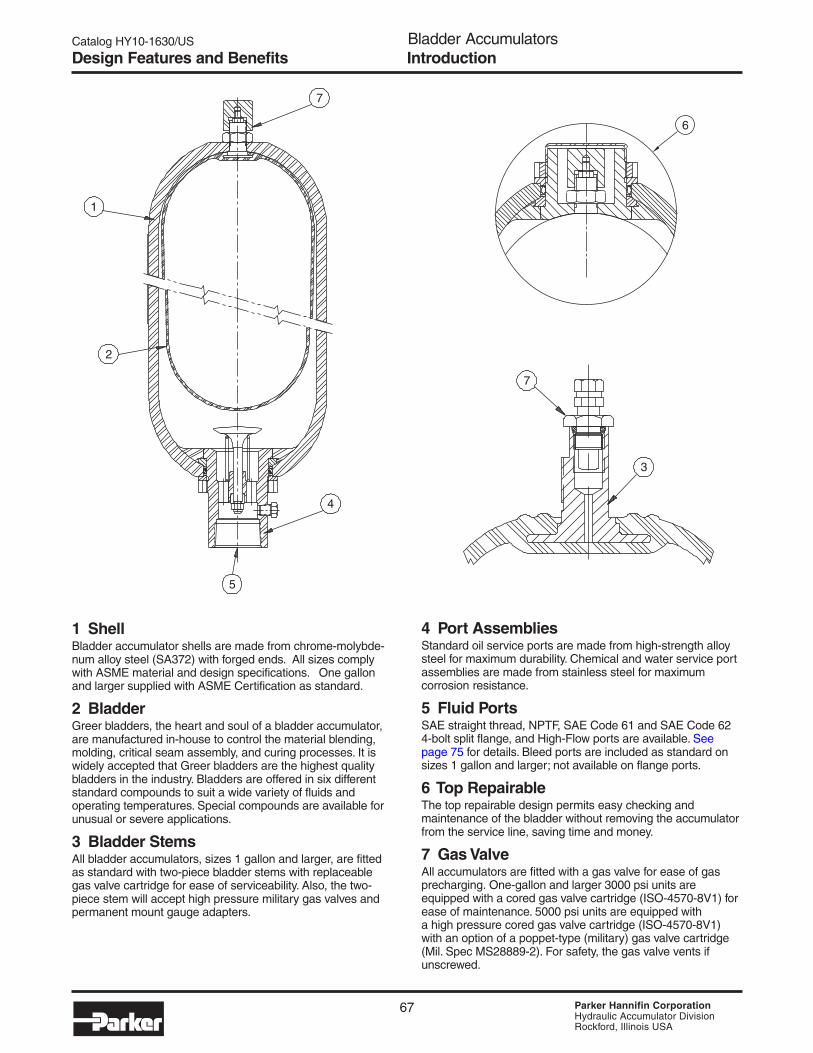
1 ShellBladder accumulator shells are made from chrome-molybde-num alloy steel (SA372) with forged ends. All sizes complywith ASME material and design specifications. One gallonand larger supplied with ASME Certification as standard.
2 BladderGreer bladders, the heart and soul of a bladder accumulator,are manufactured in-house to control the material blending,molding, critical seam assembly, and curing processes. It iswidely accepted that Greer bladders are the highest qualitybladders in the industry. Bladders are offered in six differentstandard compounds to suit a wide variety of fluids andoperating temperatures. Special compounds are available forunusual or severe applications.
3 Bladder StemsAll bladder accumulators, sizes 1 gallon and larger, are fittedas standard with two-piece bladder stems with replaceablegas valve cartridge for ease of serviceability. Also, the two-piece stem will accept high pressure military gas valves andpermanent mount gauge adapters.
4 Port AssembliesStandard oil service ports are made from high-strength alloysteel for maximum durability. Chemical and water service portassemblies are made from stainless steel for maximumcorrosion resistance.
5 Fluid PortsSAE straight thread, NPTF, SAE Code 61 and SAE Code 624-bolt split flange, and High-Flow ports are available. Seepage 75 for details. Bleed ports are included as standard onsizes 1 gallon and larger; not available on flange ports.
6 Top RepairableThe top repairable design permits easy checking andmaintenance of the bladder without removing the accumulatorfrom the service line, saving time and money.
7 Gas ValveAll accumulators are fitted with a gas valve for ease of gasprecharging. One-gallon and larger 3000 psi units areequipped with a cored gas valve cartridge (ISO-4570-8V1) forease of maintenance. 5000 psi units are equipped witha high pressure cored gas valve cartridge (ISO-4570-8V1)with an option of a poppet-type (military) gas valve cartridge(Mil. Spec MS28889-2). For safety, the gas valve vents ifunscrewed.
6
IntroductionDesign Features and Benefits

Catalog HY10-1630/US Bladder AccumulatorsIntroduction
68 Parker Hannifin CorporationHydraulic Accumulator DivisionRockford, Illinois USA
Models Dimensions, inch (mm) Hydraulic Ports WeightOil Service Gallon cu in H I lbs.Water Service (Liters) (Liters) A B C D E F G (Thread) (Thread) (Kg.)BAC10B3T01A1 10 cu in 12 11.18 1.56 2.25 1.03 0.94 7.75 0.94 SAE#8 N/A 3.5BAC10B3T01WA1 (0.16) (0.21) (284) (40) (57) (26) (24) (197) (24) (3/4 - 16) (1.6)
BA001B3T01A1 1 Pt. 31 10.75 2.00 3.40 1.39 1.31 6.87 0.94 SAE #12 N/A 8BA001B3T01WA1 (0.47) (0.51) (273) (51) (86) (35) (33) (174) (24) (1-1/16 - 12) (3.6)
BA002B3T01A1 1 Qt. 66 11.12 2.00 4.50 1.62 1.50 7.63 0.94 SAE #12 N/A 10BA002B3T01WA1 (0.95) (1.08) (282) (51) (114) (41) (38) (194) (24) (1-1/16 - 12) (4.5)
BA005B3T01A1 150 cu in 156 19.56 2.08 4.50 1.62 1.50 15.50 0.94 SAE #16 N/A 20BA005B3T01WA1 (2.5) (2.56) (497) (53) (114) (41) (38) (394) (24) (1-5/16 - 12) (9.1)
BA01B3T01A1 1 231 17.00 3.50 6.75 2.37 2.13 11.36 1.25 SAE #20 SAE #6 34BA01B3T01WA1 (3.79) (3.79) (432) (89) (171) (60) (54) (289) (32) (1-5/8 - 12) (9/16 - 18) (15)
BA02B3T01A1 2.5 556 21.38 3.62 9.06 3.00 2.88 15.50 1.25 SAE #24 SAE #6 80BA02B3T01WA1 (9.46) (9.11) (543) (92) (230) (76) (73) (394) (32) (1-7/8 - 12) (9/16 - 18) (36)
BA05B3T01A1 5 1124 33.38 3.62 9.06 3.00 2.88 27.50 1.25 SAE #24 SAE #6 120BA05B3T01WA1 (18.9) (18.42) (848) (92) (230) (76) (73) (700) (32) (1-7/8 - 12) (9/16 - 18) (55)
BA10B3T01A1 10 2097 54.38 3.62 9.06 3.00 2.88 48.50 1.25 SAE #24 SAE #6 220BA10B3T01WA1 (37.9) (34.36) (1382) (92) (230) (76) (73) (1231) (32) (1-7/8 - 12) (9/16 - 18) (100)
BA11B3T01A1 11 2400 59.88 3.62 9.06 3.00 2.88 54.00 1.25 SAE #24 SAE #6 240BA11B3T01WA1 (41.6) (39.33) (1520) (92) (230) (76) (73) (1371) (32) (1-7/8 - 12) (9/16 - 18) (109)
BA15B3T01A1 15 3267 77.88 3.62 9.06 3.00 2.88 72.00 1.25 SAE #24 SAE #6 305BA15B3T01WA1 (56.8) (53.54) (1978) (92) (230) (76) (73) (1830) (32) (1-7/8 - 12) (9/16 - 18) (139)
The simplicity and cost effectiveness of the bottom repairabledesign has made it the “Industry Standard” bladder accumula-tor. Sizes range from 10 cu in to 15 gallons.
Models Dimensions, inch (mm) Hydraulic Ports WeightOil Service Gallon cu in H I lbs.Water Service (Liters) (Liters) A B C D E F G (Thread) (Thread) (Kg.)BA01B5T01A1 1 231 17.25 3.25 7.14 2.25 N/A 11.44 1.44 SAE #20 SAE #6 50BA01B5T01WA1 (3.79) (3.79) (438) (83) (181) (57) (291) (37) (1-5/8 - 12) (9/16 - 18) (23)
BA02B5T01A1 2.5 556 22.55 3.88 9.63 3.00 2.88 16.12 2.50 SAE #24 SAE #6 120BA02B5T01WA1 (9.46) (9.11) (573) (99) (245) (76) (73) (409) (64) (1-7/8 - 12) (9/16 - 18) (55)
BA05B5T01A1 5 1124 34.80 3.88 9.63 3.00 2.88 28.36 2.50 SAE #24 SAE #6 200BA05B5T01WA1 (18.9) (18.42) (884) (99) (245) (76) (73) (720) (64) (1-7/8 - 12) (9/16 - 18) (91)
BA10B5T01A1 10 2097 55.30 3.88 9.63 3.00 2.88 48.88 2.50 SAE #24 SAE #6 335BA10B5T01WA1 (37.9) (34.36) (1405) (99) (245) (76) (73) (1242) (64) (1-7/8 - 12) (9/16 - 18) (152)
BA15B5T01A1 15 3267 76.80 3.88 9.63 3.00 2.88 70.38 2.50 SAE #24 SAE #6 485BA15B5T01WA1 (56.8) (53.54) (1951) (99) (245) (76) (73) (1788) (64) (1-7/8 - 12) (9/16 - 18) (220)
5000 PSI (345 Bar)2
1) Note: 1 thru 15 gallon sizes available with 4000 PSI (275 Bar) Appendix 22 Approval.
3000 PSI (207 Bar)1
2) Note: Available with 6600 PSI (455 Bar) Appendix 22 Approval.
CG (Hex)
I
E FLAT
HD
AF
B
Bottom Repairable Models, Capacities and Dimensions
GasVolume
NominalSize
NominalSize
GasVolume

Catalog HY10-1630/UStontent Bladder AccumulatorsIntroduction
69 Parker Hannifin CorporationHydraulic Accumulator DivisionRockford, Illinois USA
The Top Repairable Accumulator permits easy checking andmaintenance of the bladder without removing the accumulatorfrom the service line, saving time and money. Sizes rangefrom 2-1/2 to 15 gallons.
Models Dimensions, inch (mm) Hydraulic Ports WeightOil Service Gallon cu in H I lbs.Water Service (Liters) (Liters) A B C D E F G (Thread) (Thread) (Kg.)BA02T3T01A1 2.5 541 20.50 3.62 9.06 3.00 2.88 15.38 1.25 SAE #24 SAE #6 80BA02T3T01WA1 (9.45) (8.87) (521) (92) (230) (76) (73) (391) (32) (1-7/8 - 12) (9/16 - 18) (36)
BA05T3T01A1 5 1110 32.75 3.62 9.06 3.00 2.88 27.63 1.25 SAE #24 SAE #6 120BA05T3T01WA1 (18.9) (18.19) (832) (92) (230) (76) (73) (702) (32) (1-7/8 - 12) (9/16 - 18) (55)
BA10T3T01A1 10 2083 53.25 3.62 9.06 3.00 2.88 48.13 1.25 SAE #24 SAE #6 220BA10T3T01WA1 (37.8) (34.13) (1353) (92) (230) (76) (73) (1223) (32) (1-7/8 - 12) (9/16 - 18) 100
BA11T3T01A1 11 2386 59.00 3.62 9.06 3.00 2.88 53.88 1.25 SAE #24 SAE #6 240BA11T3T01WA1 (41.6) (39.1) (1499) (92) (230) (76) (73) (1369) (32) (1-7/8 - 12) (9/16 - 18) (109)
BA15T3T01A1 15 3253 77.38 3.62 9.06 3.00 2.88 71.75 1.25 SAE #24 SAE #6 305BA15T3T01WA1 (56.7) (53.31) (1965) (92) (230) (76) (73) (1822) (32) (1-7/8 - 12) (9/16 - 18) (139)
Models Dimensions, inch (mm) Hydraulic Ports WeightOil Service Gallon cu in H I lbs.Water Service (Liters) (Liters) A B C D E F G (Thread) (Thread) (Kg.)BA02T5T01A1 2.5 541 21.68 3.88 9.63 3.00 2.88 15.88 1.25 SAE #24 SAE #6 120BA02T5T01WA1 (9.46) (8.87) (551) (99) (245) (76) (73) (403) (32) (1-7/8 - 12) (9/16 - 18) (55)
BA05T5T01A1 5 1110 33.92 3.88 9.63 3.00 2.88 23.13 1.25 SAE #24 SAE #6 220BA05T5T01WA1 (18.9) (18.19) (862) (99) (245) (76) (73) (715) (32) (1-7/8 - 12) (9/16 - 18) (100)
BA10T5T01A1 10 2083 54.42 3.88 9.63 3.00 2.88 48.63 1.25 SAE #24 SAE #6 335BA10T5T01WA1 (37.8) (34.13) (1382) (99) (245) (76) (73) (1235) (32) (1-7/8 - 12) (9/16 - 18) (152)
BA15T5T01A1 15 3253 75.92 3.88 9.63 3.00 2.88 70.13 1.25 SAE #24 SAE #6 485BA15T5T01WA1 (56.8) (53.31) (1928) (99) (245) (76) (73) (1781) (32) (1-7/8 - 12) (9/16 - 18) (220)
2) Note: Available with 6600 PSI (455 Bar) Appendix 22
3000 PSI (207 Bar)1
1) Note: Available with 4000 PSI (275 Bar) Appendix 22
5000 PSI (345 Bar)2
C
G (Hex)
E FLATH
I
D
A
B
F
Top Repairable Models, Capacities and Dimensions
NominalSize
GasVolume
NominalSize
GasVolume

Catalog HY10-1630/US Bladder AccumulatorsIntroduction
70 Parker Hannifin CorporationHydraulic Accumulator DivisionRockford, Illinois USA
Medium Flow Models, Capacities and Dimensions
For systems requiring a faster “dumping” rate, the MediumFlow accumulator incorporates a larger port assemblycapable of flows up to 480 GPM (1819 LPM). Sizes rangefrom 2-1/2 to 15 gallons.
Optional Flange Port Details
2.25
Groove for2-232 O-ring
4.870∅3.000
∅6.887 B.C.
4.87
0
∅1.300 (4)
Models Dimensions, in (mm) H Port WeightMale Str. Thd. Gal. cu in A B C D F G Hydraulic I lbsMale NPT (L) (L) Port (Thread) (Kg.)
BA02B3C01A12.5 556 22.87 5.88 9.06 3.63 15.25 1.25
M95x2SAE #6 80
(9.46) (9.11) (581) (149) (230) (92) (387) (32) (9/16-18) (36)
BA05B3C01A15 1124 35.12 5.88 9.06 3.63 27.50 1.25
M95x2SAE #6 120
(18.9) (18.42) (892) (149) (230) (92) (699) (32) (9/16-18) (55)
BA10B3C01A110 2097 55.62 5.88 9.06 3.63 48.00 1.25
M95x2SAE #6 220
(37.9) (34.36) (1413) (149) (230) (92) (1219) (32) (9/16-18) (100)
BA11B3C01A111 2400 61.37 5.88 9.06 3.63 53.75 1.25
M95x2SAE #6 240
(41.6) (39.33) (1559) (149) (230) (92) (1365) (32) (9/16-18) (109)
BA15B3C01A115 3267 79.12 5.88 9.06 3.63 71.5 1.25
M95x2SAE #6 305
(56.8) (53.54) (2010) (149) (230) (92) (1816) (32) (9/16-18) (139)
3000 PSI (207 Bar)Nom.Size
GasVol.
G
H
E
D
I
B
A
F
C
Note: Accumulator assembly does not include flange.
NOTE: Medium flow bladder accumulators not available with Appendix 22 option.
Catalog HY10-1630/UStontent Bladder AccumulatorsIntroduction
71 Parker Hannifin CorporationHydraulic Accumulator DivisionRockford, Illinois USA
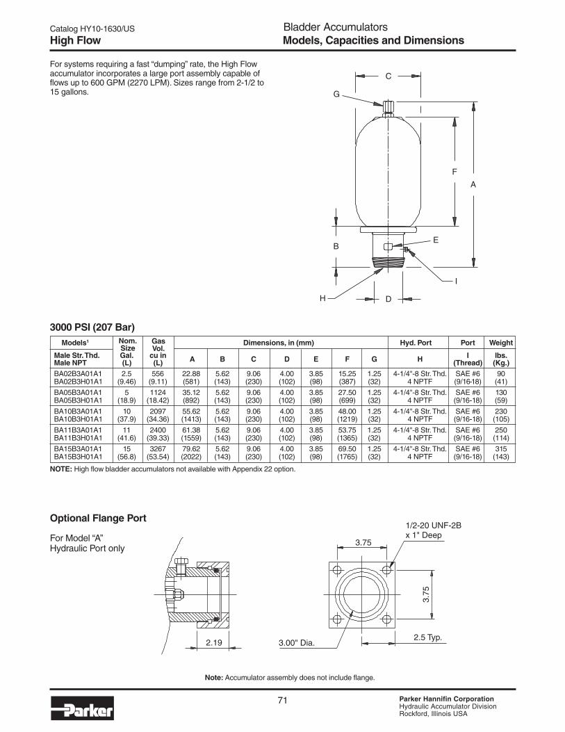
For systems requiring a fast “dumping” rate, the High Flowaccumulator incorporates a large port assembly capable offlows up to 600 GPM (2270 LPM). Sizes range from 2-1/2 to15 gallons.
Models1 Dimensions, in (mm) Hyd. Port Port Weight
Male Str. Thd. Gal. cu in A B C D E F G H I lbs.
Male NPT (L) (L) (Thread) (Kg.)BA02B3A01A1 2.5 556 22.88 5.62 9.06 4.00 3.85 15.25 1.25 4-1/4"-8 Str. Thd. SAE #6 90BA02B3H01A1 (9.46) (9.11) (581) (143) (230) (102) (98) (387) (32) 4 NPTF (9/16-18) (41)
BA05B3A01A1 5 1124 35.12 5.62 9.06 4.00 3.85 27.50 1.25 4-1/4"-8 Str. Thd. SAE #6 130BA05B3H01A1 (18.9) (18.42) (892) (143) (230) (102) (98) (699) (32) 4 NPTF (9/16-18) (59)
BA10B3A01A1 10 2097 55.62 5.62 9.06 4.00 3.85 48.00 1.25 4-1/4"-8 Str. Thd. SAE #6 230BA10B3H01A1 (37.9) (34.36) (1413) (143) (230) (102) (98) (1219) (32) 4 NPTF (9/16-18) (105)
BA11B3A01A1 11 2400 61.38 5.62 9.06 4.00 3.85 53.75 1.25 4-1/4"-8 Str. Thd. SAE #6 250BA11B3H01A1 (41.6) (39.33) (1559) (143) (230) (102) (98) (1365) (32) 4 NPTF (9/16-18) (114)
BA15B3A01A1 15 3267 79.62 5.62 9.06 4.00 3.85 69.50 1.25 4-1/4"-8 Str. Thd. SAE #6 315BA15B3H01A1 (56.8) (53.54) (2022) (143) (230) (102) (98) (1765) (32) 4 NPTF (9/16-18) (143)
3000 PSI (207 Bar)
Optional Flange Port
For Model “A”Hydraulic Port only
High Flow Models, Capacities and Dimensions
C
F
A
B
D
E
I
H
G
2.19 3.00" Dia.
3.75
3.75
2.5 Typ.
1/2-20 UNF-2Bx 1" Deep
Nom.Size
GasVol.
Note: Accumulator assembly does not include flange.
NOTE: High flow bladder accumulators not available with Appendix 22 option.

Catalog HY10-1630/US Bladder AccumulatorsIntroduction
72 Parker Hannifin CorporationHydraulic Accumulator DivisionRockford, Illinois USA
The Transfer Barrier accumulator provides positive separationbetween two different medias or can be used with gas bottles.Sizes range from 2-1/2 to 15 gallons.
Nominal GasModels Size Volume Dimensions, in (mm) Hydraulic/Gas Ports Weight
Oil Service Gallon cu in H I J lbs.Water Service (Liters) (Liters) A B C D E F G (Thread) (Thread) (Thread) (Kg.)BT02B3TT01A1 2.5 556 21.25 3.62 9.06 3.00 2.88 15.62 2.00 SAE #24 SAE #6 SAE #12 80BT02B3TT01WA1 (9.45) (9.11) (540) (92) (230) (76) (73) (397) (51) (1-7/8 - 12) (9/16 - 18) (1-1/16 - 12) (36)
BT05B3TT01A1 5 1124 33.50 3.62 9.06 3.00 2.88 27.88 2.00 SAE #24 SAE #6 SAE #12 120BT05B3TT01WA1 (18.9) (18.42) (851) (92) (230) (76) (73) (708) (51) (1-7/8 - 12) (9/16 - 18) (1-1/16 - 12) (55)
BT10B3TT01A1 10 2097 54.00 3.62 9.06 3.00 2.88 43.38 2.00 SAE #24 SAE #6 SAE #12 220BT10B3TT01WA1 (37.8) (34.36) (1372) (92) (230) (76) (73) (1102) (51) (1-7/8 - 12) (9/16 - 18) (1-1/16 - 12) (100)
BT11B3TT01A1 11 2400 59.75 3.62 9.06 3.00 2.88 54.12 2.00 SAE #24 SAE #6 SAE #12 240BT11B3TT01WA1 (41.6) (39.33) (1518) (92) (230) (76) (73) (1375) (51) (1-7/8 - 12) (9/16 - 18) (1-1/16 - 12) (109)
BT15B3TT01A1 15 3267 77.62 3.62 9.06 3.00 2.88 72.00 2.00 SAE #24 SAE #6 SAE #12 305BT15B3TT01WA1 (56.7) (53.54) (1972) (92) (230) (76) (73) (1829) (51) (1-7/8 - 12) (9/16 - 18) (1-1/16 - 12) (139)
3000 PSI (207 Bar)1
1) Note: Available with 4000 PSI (275 Bar) Appendix 22
Nominal GasModels Size Volume Dimensions, in (mm) Hydraulic/Gas Ports Weight
Oil Service Gallon cu in H I J lbs.Water Service (Liters) (Liters) A B C D E F G (Thread) (Thread) (Thread) (Kg.)BT02B5TT01A1 2.5 556 22.55 3.62 9.63 3.00 2.88 16.12 2.00 SAE #24 SAE #6 SAE #12 120BT02B5TT01WA1 (9.45) (9.11) (573) (92) (245) (76) (73) (409) (51) (1-7/8 - 12) (9/16 - 18) (1-1/16 - 12) (55)
BT05B5TT01A1 5 1124 34.80 3.62 9.63 3.00 2.88 28.36 2.00 SAE #24 SAE #6 SAE #12 200BT05B5TT01WA1 (18.9) (18.42) (884) (92) (245) (76) (73) (720) (51) (1-7/8 - 12) (9/16 - 18) (1-1/16 - 12) (91)
BT10B5TT01A1 10 2097 55.30 3.62 9.63 3.00 2.88 48.88 2.00 SAE #24 SAE #6 SAE #12 335BT10B5TT01WA1 (37.8) (34.36) (1405) (92) (245) (76) (73) (1242) (51) (1-7/8 - 12) (9/16 - 18) (1-1/16 - 12) (152)
BT15B5TT01A1 15 3267 76.80 3.62 9.63 3.00 2.88 70.38 2.00 SAE #24 SAE #6 SAE #12 485BT15B5TT01WA1 (56.7) (53.54) (1951) (92) (245) (76) (73) (1788) (51) (1-7/8 - 12) (9/16 - 18) (1-1/16 - 12) (220)
5000 PSI (345 Bar)2
2) Note: Available with 6600 PSI (455 Bar) Appendix 22
Models, Capacities and DimensionsTransfer Barrier
C G Hex
AF
B
E Flat
DH I
J

Catalog HY10-1630/UStontent Bladder AccumulatorsIntroduction
73 Parker Hannifin CorporationHydraulic Accumulator DivisionRockford, Illinois USA
Dimensions, inch (mm) Ports WeightGallon H I lbs.
Models (Liters) A B C D E F G (Thread) (Thread) (Kg.)
BG01B3T01A1 1 17.00 3.50 6.75 2.37 2.13 11.36 1.25 SAE #20 SAE #6 34(3.79) (432) (89) (171) (60) (54) (289) (32) (1-5/8 - 12) (9/16 - 18) (15)
BG02B3T01A1 2.5 21.25 3.62 9.06 3.00 2.88 15.62 1.25 SAE #24 SAE #6 80(9.46) (540) (92) (230) (76) (73) (397) (32) (1-7/8 - 12) (9/16 - 18) (36)
BG05B3T01A1 5 33.50 3.62 9.06 3.00 2.88 27.88 1.25 SAE #24 SAE #6 120(18.9) (851) (92) (230) (76) (73) (708) (32) (1-7/8 - 12) (9/16 - 18) (55)
BG10B3T01A1 10 54.00 3.62 9.06 3.00 2.88 43.38 1.25 SAE #24 SAE #6 220(37.9) (1372) (92) (230) (76) (73) (1102) (32) (1-7/8 - 12) (9/16 - 18) (100)
BG11B3T01A1 11 59.75 3.62 9.06 3.00 2.88 54.12 1.25 SAE #24 SAE #6 240(41.6) (1518) (92) (230) (76) (73) (1375) (32) (1-7/8 - 12) (9/16 - 18) (109)
BG15B3T01A1 15 77.62 3.62 9.06 3.00 2.88 72.00 1.25 SAE #24 SAE #6 305(56.8) (1972) (92) (230) (76) (73) (1829) (32) (1-7/8 - 12) (9/16 - 18) (139)
Where space does not permit the installation of the requiredaccumulator, a smaller accumulator may be used by connect-ing it to an auxiliary gas bottle(s) that may be located in somenearby spot where space is available. (See Large Gas Bottlesfor additional offerings and page 104 for sizing information.)Sizes range from 1 to 15 gallons.
3000 PSI (207 Bar)1
5000 PSI (345 Bar)2
Dimensions, inch (mm) Ports WeightGallon H I lbs.
Models (Liters) A B C D E F G (Thread) (Thread) (Kg.)
BG01B5T1A1 1 17.25 3.25 7.14 2.25 N/A 11.44 1.44 SAE #20 SAE #6 50(3.79) (438) (83) (181) (57) (291) (37) (1-5/8 - 12) (9/16 - 18) (23)
BG02B5T1A1 2.5 22.55 3.88 9.63 3.00 2.88 16.12 2.50 SAE #24 SAE #6 120(9.46) (573) (99) (245) (76) (73) (409) (64) (1-7/8 - 12) (9/16 - 18) (55)
BG05B5T1A1 5 34.80 3.88 9.63 3.00 2.88 28.36 2.50 SAE #24 SAE #6 200(18.9) (884) (99) (245) (76) (73) (720) (64) (1-7/8 - 12) (9/16 - 18) (91)
BG10B5T1A1 10 55.30 3.88 9.63 3.00 2.88 48.88 2.50 SAE #24 SAE #6 335(37.9) (1405) (99) (245) (76) (73) (1242) (64) (1-7/8 - 12) (9/16 - 18) (152)
BG15B5T1A1 15 76.80 3.88 9.63 3.00 2.88 70.38 2.50 SAE #24 SAE #6 485(56.8) (1951) (99) (245) (76) (73) (1788) (64) (1-7/8 - 12) (9/16 - 18) (220)
2) Note: Available with 6600 PSI (455 Bar) Appendix 22
1) Note: Available with 4000 PSI (275 Bar) Appendix 22
Models, Capacities and DimensionsGas Bottles
DE (Flat)
B
IH
AF
GC
NominalSize
NominalSize

Catalog HY10-1630/US Bladder AccumulatorsIntroduction
74 Parker Hannifin CorporationHydraulic Accumulator DivisionRockford, Illinois USA
Standard and Optional BladdersA variety of bladders are offered to suit a wide range of fluids and operating temperatures. The following table lists the optionalbladders available, their recommended operating temperature ranges, and the types of fluids that are generally compatible.
Recommended MaximumSeal Operating Temperature with General ApplicationCode Polymer Temperature Range Reduced Life & Compatibility*
01 Buna-Nitrile -20°F to 200°F 225°F Standard Compound – Compatible-29°C to 93°C 107°C with most mineral oil-based fluids
03 Hi-Temp. -20°F to 225°F 250°F Compatible with most mineral oil-based fluidsNitrile -29°C to 107°C 121°C with enhanced high temperature performance
04 Hydrin -40°F to 225°F 250°F Compatible with most mineral oil-based fluids(Lo-Temp.) -40°C to 107°C 121°C with enhanced low temperature performance
06 Butyl -40°F to 200°F 300°F Compatible with most phosphate ester fluids-40°C to 93°C 149°C and some synthetic fluids
08 Ethylene -40°F to 200°F 300°F Compatible with some synthetic fluidsPropylene -40°C to 93°C 149°C and water
28 Fluorocarbon -10°F to 250°F 400°F Compatible with most mineral oil-based fluidsElastomer -23°C to 121°C 204°C at higher temperatures and some exotic fluids
*Note: Consult your local distributor or the factory for fluid compatibility information.Temperature ranges may vary depending upon the fluid used in the hydraulic system.
OptionsBladders, Water Service, Gas Valves
Water & Chemical Service Options (W)Bladder accumulators are available with a water and chemical resistance option. The (W) designation includes an internallySkotchkoted shell and stainless steel or electroless nickel plated port assembly. The Skotchkote offers added protection againstmore corrosive fluids.
Gas ValvesTwo types of gas valves are available on bladder accumula-tors. 3000 PSI rated models are offered with a cored gasvalve cartridge (cartridge type, 1 gal. & up, ISO-4570-8V1)as standard. 5000 PSI units are equipped with a highpressure cored gas valve cartridge (ISO-4570-8V1) with anoption of a heavy duty (military) poppet-type gas valvecartridge (Mil. Spec. MS28889-2).
Standard Gas Valve Military Gas Valve
#5 SAE THREAD1/2–20 UNF-2A
1/2–20 UNF-2A
Catalog HY10-1630/UStontent Bladder AccumulatorsIntroduction
75 Parker Hannifin CorporationHydraulic Accumulator DivisionRockford, Illinois USA
Bla
dder
Standard Port
Optional Ports
SAE Str. SAE 4-Bolt Undersize ISOThread Split Flange* NPTF NPTF BSPP 6149-1
Sizes Code T Code F Code U Code X Code R Code Y3000 PSI (207 Bar) Models
10 cu in SAE #8 – 3/4" Male – – M 8x1.51 pt., 1 qt. SAE #12 – 3/4" – G 3/4" M 27x2150 cu in SAE #16 – 1" – G 1" M 33x2
1 gal. SAE #20 1-1/4", Code 61 1-1/4" – G 1-1/4" M 42x22½ to 15 gal. SAE #24 2", Code 61 2" 1-1/4" G 2" M 48x2
5000 PSI (345 Bar) Models1 gal. SAE #20 1-1/4", Code 62 1-1/4" – G 1-1/4" M 42x2
2½ to 15 gal. SAE #24 1-1/2", Code 62 2" – G 2" M 48x2
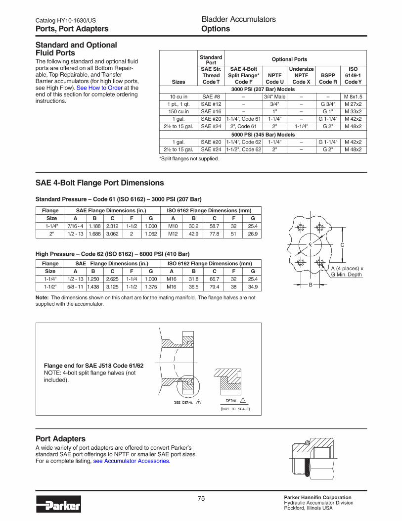
SAE 4-Bolt Flange Port Dimensions
Standard Pressure – Code 61 (ISO 6162) – 3000 PSI (207 Bar)
High Pressure – Code 62 (ISO 6162) – 6000 PSI (410 Bar)
Flange SAE Flange Dimensions (in.) ISO 6162 Flange Dimensions (mm)Size A B C F G A B C F G1-1/4" 7/16 - 4 1.188 2.312 1-1/2 1.000 M10 30.2 58.7 32 25.4
2" 1/2 - 13 1.688 3.062 2 1.062 M12 42.9 77.8 51 26.9
Flange SAE Flange Dimensions (in.) ISO 6162 Flange Dimensions (mm)Size A B C F G A B C F G1-1/4" 1/2 - 13 1.250 2.625 1-1/4 1.000 M16 31.8 66.7 32 25.4
1-1/2" 5/8 - 11 1.438 3.125 1-1/2 1.375 M16 36.5 79.4 38 34.9
Standard and OptionalFluid PortsThe following standard and optional fluidports are offered on all Bottom Repair-able, Top Repairable, and TransferBarrier accumulators (for high flow ports,see High Flow). See How to Order at theend of this section for complete orderinginstructions.
Port AdaptersA wide variety of port adapters are offered to convert Parker’sstandard SAE port offerings to NPTF or smaller SAE port sizes.For a complete listing, see Accumulator Accessories.
OptionsPorts, Port Adapters
C
B
F
A (4 places) xG Min. Depth
*Split flanges not supplied.
Note: The dimensions shown on this chart are for the mating manifold. The flange halves are notsupplied with the accumulator.
Flange end for SAE J518 Code 61/62NOTE: 4-bolt split flange halves (notincluded).

Catalog HY10-1630/US Bladder AccumulatorsIntroduction
76 Parker Hannifin CorporationHydraulic Accumulator DivisionRockford, Illinois USA
Safety Fuse OptionsSafety Fuses are used as a safety device on accumulatorsand gas bottles to prevent over-pressurization of gas dueto external heat or hydraulic pressure (set at 140% ofmaximum system pressure to avoid rupture disk fatigueand premature failure). The rupture disks are calibrated torupture at a pre-determined pressure. Safety fuses areavailable on most sizes of piston and bladder accumulatorsand gas bottles. Safety fuses can be installed on 1 gallon &larger accumulators by using the “Fuse Adapter” as shownto the right. The safety fuse assembly and/or fuse adaptermust be ordered separately.
Mounting, Charging & GaugingAccessoriesGreer offers a wide variety of mounting, charging andgauging accessories. See “Accumulator Accessories”.
Special OptionsIf your application requires a bladder accumulator orspecial option that falls outside of our broad offering,consult your local distributor, Greer representative, or thefactory with your specific requirements. We have themanufacturing and engineering expertise to design andbuild bladder accumulators to your exacting requirements,from simple modifications to standard units to completedesigns from scratch. Some example of our past specialdesigns include:
• Special and Stainless Steel Materials
• Special Bladder Compounds• Suction Stabilizer• Pulsation Dampener
• Special Certifications
Consult our experts with your next bladder accumulator requirement!
Description Part Number Safety Fuse Assembly1 086471xxxx
Replacement Rupture Disks 756003xxxx
Fuse Adapter 1468970002
1) Assembly includes housing and rupture disk, xxxx = pressuresetting in 100 psi increments, i.e., for an assembly with a 2000 PSIsetting, order P/N 0864712000.
Options and AccessoriesSafety Fuse, Special
1.25#8 SAEStraightPort Th’d
#5 SAEStraightPort Th’d
#5 SAEStraightPort Th’d0.48
3.77
Fuse Adapter
1.44
0.950.70
1.55
Fuse
#8 SAE3/4-16 UNF-2A

Catalog HY10-1630/UStontent Bladder AccumulatorsIntroduction
77 Parker Hannifin CorporationHydraulic Accumulator DivisionRockford, Illinois USA
A full range of genuine Greer replacement bladder kits are available to bring your accumulator back to original condition shouldreplacement become necessary. All bladder kits include port o-ring, backup seals and gas valves with secondary seals.NOTE: Part numbers shaded in gray will be phased out.
Replacement Kits
Bladder & Seal Compound
Group 01 Group 03 Group 04 Group 06 Group 08 Group 28Size Brand Nitrile (NBR) Hi Temp (NBR) Hydrin Butyl EPR Fluorocarbon
3,000 PSI Standard Bladder Kits (Top & Bottom Repairable)
10 Cu. In. Greer 702900 702901 702902 702903 702904 702906
Parker 0850693C10 0870433C10 0856663C10 0850703C10 0851053C10 0851043C10
1 Pt. Greer 702914 702915 702916 702917 702918 702920
Parker 0850693001 0870433001 0856663001 0850703001 0851053001 0851043001
1 Qt. Greer 702928 702929 702930 702931 702932 702934
Parker 0850693002 0870433002 0856663002 0850703002 0851053002 0851043002
150 Cu. In. Greer 702942 702943 702944 702945 702946 702948
Parker 0850693006 0870433006 0856663006 0850703006 0851053006 0851043006
1 Gal. Greer 702956 702957 702958 702959 702960 702962
Parker 0850693010 0870433010 0856663010 0850703010 0851053010 0851043010
2 1/2 Gal. Greer 702970 702971 702972 702973 702974 702976
Parker 0850693025 0870433025 0856663025 0850703025 0851053025 0851043025
5 Gal. Greer 702984 702985 702986 702987 702988 702990
Parker 0850693050 0870433050 0856663050 0850703050 0851053050 0851043050
10 Gal. Greer 702998 702999 703000 703001 703002 703004
Parker 0850693100 0870433100 0856663100 0850703100 0851053100 0851043100
11 Gal. Greer 703012 703013 703014 703015 703016 703018
Parker 0850693110 0870433110 0856663110 0850703110 0851053110 0851043110
15 Gal. Greer 703026 703027 703028 703029 703030 703032
Parker 0850693150 0870433150 0856663150 0850703150 0851053150 0851043150
25 Gal. Greer 703340 704007 704008 704009 703341 703342
Parker 0850693250 0870433250 0856663250 0850703250 0851053250 0851043250
40 Gal. Greer 703346 704013 704014 704015 703347 703348
Parker 0850693400 0870433400 0856663400 0850703400 0851053400 0851043400
5,000 PSI Bottom Repairable Bladder Kits (2" Valve Stem - New Style)
1 Gal. Greer 8706135010 8706185010 8706175010 8706145010 8706145010 8706155010
7/8" ∅ Stem Parker 8706135010 8706185010 8706175010 8706145010 8706145010 8706155010
1 Gal. Greer 704060 704061 704062 704063 704064 704066
1" ∅ Stem Parker 0850695010 0870435010 0856665010 080705010 0851055010 0851045010
2 1/2 Gal. Greer 706000 706001 706002 706003 706004 706006
Parker 0861905025 0872685025 0861945025 0861915025 0861935025 0861925025
5 Gal. Greer 706010 706011 706012 706013 706014 706016
Parker 0861905050 0872685050 0861945050 0861915050 0861935050 0861925050
10 Gal. Greer 706020 706021 706022 706023 706024 706026
Parker 0861905100 0872685100 0861945100 0861915100 0861935100 0861925100
15 Gal. Greer 706030 706031 706032 706033 706034 706036
Parker 0861905150 0872685150 0861945150 0861915150 0861935150 0861925150
5,000 PSI Bottom Repairable Bladder Kits (7/8" Valve Stem - Old Style)
2 1/2 Gal. Parker 0850695025 0870435025 0856665025 0850705025 0851055025 0851045025
5 Gal. Parker 0850695050 0870435050 0856665050 0850705050 0851055050 0851045050
10 Gal. Parker 0850695100 0870435100 0856665100 0850705100 0851055100 0851045100
15 Gal. Parker 0850695150 0870435150 0856665150 0850705150 0851055150 0851045150
Bladder Kits

Catalog HY10-1630/US Bladder AccumulatorsIntroduction
78 Parker Hannifin CorporationHydraulic Accumulator DivisionRockford, Illinois USA
How to Order Bladder AccumulatorsBladder accumulators and gas bottles can be specified by using the symbols in the chart below to develop a model number. Selectonly those symbols that represent the features desired, and place them in the sequence indicated by the example at the top of thechart.
Gas Hyd. Bladder/Seal Design DesignSeries Size Construction Pressure Port1 Compound Modification Code
BA 001 B T 01 –A 1
Series
BA AccumulatorBG Gas BottleBT Transfer Barrier
3
Ordering InformationModel Code and Options
Available3000 5000
Size PSI PSI
C10 10 Cl •001 1 Pint •002 1 Quart •005 150 Cl •01 1 Gallon • •02 2½ Gallon • •05 5 Gallon • •10 10 Gallon • •11 11 Gallon •15 15 Gallon • •
Type of Construction
B Bottom RepairableStandard on all sizes
T Top RepairableOptional for 2½ Gallon and up
Working Pressure
3 3,000 PSI (330 bar CE only)4 4,000 PSI5 5,000 PSI6 6,600 PSIY Special
Hydraulic Port
T SAE Straight Thread O-Ring (Standard)10 Cl SAE #81 Pint & 1 Quart SAE #12150 Cl SAE #161 Gallon SAE #202½ Gallon thru 15 Gallon SAE #24
U NPT Pipe (No Cost Option)10 Cl 3/4” NPT Male1 Pint & 1 Quart 3/4” NPTF150 Cl 1” NPTF1 Gallon 1 1/4” NPTF2½ Gallon thru 15 Gallon 2” NPTF
F SAE 4-Bolt Split Flange (No Cost Option)10 Cl thru 150 Cl (3K) N/A1 Gallon (3K) 1 1/4” Code 61
(3000 PSI)1 Gallon (5K) 1 1/4" Code 62
(6000 PSI)2½ Gal. thru 15 Gal. (3K) 2” Code 61
(3000 PSI)2½ Gal. thru 15 Gal. (4K) 1 1/2” Code 62
(6000 PSI)2½ Gal. thru 15 Gal. (5K) 1 1/2” Code 62
(6000 PSI)H High Flow 4” NPT Male (Extra Cost Option)
Available on 2½ Gallon thru 15 Gallon Sizes only(3000 PSI)
A High Flow 4¼-8 UN-2 Straight Thread Male(Extra Cost Option)Available on 2½ Gallon thru 15 Gallon Sizes only(3000 PSI)
C Medium Flow M95x2 Straight Thread Male(Extra Cost Option)Available on 2½ Gallon thru 15 Gallon Sizes only(3000 PSI)
X NPT Pipe Undersized (No Cost Option)2½ Gallon thru 15 Gallon Sizes only(3000 PSI) 1-1/4” NPT
R BSPP10 Cl N/A1 Pint & 1 Quart 3/4-14150 Cl 1-111 Gallon 1 1/4-112½ Gallon thru 15 Gallon 2-11
Y ISO 6149-110 Cl M18 x 1.51 Pint & 1 Quart M27 x 2150 Cl M33 x 21 Gallon M42 x 22½ Gallon thru 15 Gallon M48 x 2
G Metric10 Cl M18 x 1.51 Pint & 1 Quart M27 x 2150 Cl M33 x 21 Gallon M42 x 22½ Gallon thru 15 Gallon M48 x 2
S Special
Bladder/Seal Compound
01 Buna-Nitrile (Std.)03 High Temp. Nitrile (Optional)04 Hydrin (Optional)06 Butyl (Optional)08 EPR (Optional)28 Fluoroelastomer (Optional)
Design Modification (1st Digit)
Blank StandardW Water/Chemical ServiceM MS28889-2
Design (2nd Digit)
A Standard ASME(1 Gallon & up)
D ASME (< 1 Gallon)E CE MarkingG Appendix 22 ShellS Special
Design Code
1 Standard* Number given
* 1 Gal. through 15 gal. – A.S.M.E. designwith “U” stamp.1 Pt., 1 Qt. and 150 C.I. – A.S.M.E. design,available with “U” stamp.If “U” stamp is required, it must be specifiedat time of order.
NOTE: A.S.M.E. documentation or any othercertification must be requested attime of order.

Catalog HY10-1630/UStontent Bladder AccumulatorsIntroduction
79 Parker Hannifin CorporationHydraulic Accumulator DivisionRockford, Illinois USA
Phasing Out.
See Previous
Page for Curre
nt
Model Code.
Gas Hyd. Bladder/Seal Design DesignSeries Size Construction Pressure Port1 Compound Modification Code
AB 04 B T 1 _A 1
Series
A B AccumulatorB B Gas BottleT B Transfer Barrier
3
Available3000 5000
Size PSI PSI
003 10 Cl •005 1 Pint •01 1 Quart •03 150 Cl •04 1 Gallon • •10 2½ Gallon • •20 5 Gallon • •40 10 Gallon • •44 11 Gallon •60 15 Gallon • •
Type of Construction
B Bottom RepairableStandard on all sizes
C Conventional Top RepairableOptional for 2½ Gallon and up
Working Pressure
3 3,000 PSI4 4,000 PSI5 5,000 PSI6 6,600 PSIS Special
Hydraulic Port
T SAE Straight Thread O-Ring (Standard)10 Cl SAE #81 Pint & 1 Quart SAE #12150 Cl SAE #161 Gallon SAE #202½ Gallon thru 10 Gallon SAE #24
U NPT Pipe (No Cost Option)10 Cl 3/4” NPT Male1 Pint & 1 Quart 3/4” NPTF150 Cl 1” NPTF1 Gallon 1 1/4” NPTF2½ Gallon thru 15 Gallon 2” NPTF
F SAE 4-Bolt Split Flange (No Cost Option)10 Cl thru 150 Cl (3K) N/A1 Gallon (3K) 1 1/4” Code 61
(3000 PSI)2½ Gal. thru 15 Gal. (3K) 2” Code 61
(3000 PSI)2½ Gal. thru 15 Gal. (4K) 1 1/2” Code 62
(6000 PSI)2½ Gal. thru 15 Gal. (5K) 1 1/2” Code 62
(6000 PSI)H High Flow 4” NPT Male (Extra Cost Option)
Available on 2½ Gallon thru 15 Gallon Sizes only(3000 PSI)
A High Flow 4 1/4-8 UN-2 Straight Thread Male(Extra Cost Option)Available on 2½ Gallon thru 15 Gallon Sizes only(3000 PSI)
B High Flow Flange Adapted to Above4 1/4-8 UN-2 High Flow (Extra Cost Option)Available on 2½ Gallon thru 15 Gallon Sizes only(3000 PSI)
X NPT Pipe Undersized (No Cost Option)2½ Gallon thru 15 Gallon Sizes only(3000 PSI)
R BSPP10 Cl N/A1 Pint & 1 Quart 3/4-14150 Cl 1-111 Gallon 1 1/4-112½ Gallon thru 15 Gallon 2-11
Y ISO 6149-110 Cl M18 x 1.51 Pint & 1 Quart M27 x 2150 Cl M33 x 21 Gallon M42 x 22½ Gallon thru 15 Gallon M48 x 2
S Special
Design Modification (1st Digit)
Blank StandardW Water/Chemical ServiceM MS28889-1
Design (2nd Digit)
A Standard ASME(1 Gallon & up)
D ASME (< 1 Gallon)G Appendix 22 ShellS Special
Design Code
1 Standard2 Standard 1 Quart3 2½ - 15 Gallon, 5000 psi* Number given
* 1 Gal. through 15 gal. – A.S.M.E. designwith “U” stamp.1 Pt., 1 Qt. and 150 C.I. A.S.M.E. design,available with “U” stamp. If “U” stamp isrequired, it must be specified at time oforder.
NOTE: A.S.M.E. documentation or any othercertification must be requested attime of order.
Bladder/Seal Compound
1 Buna-Nitrile (Std.)9 Hydrin (Optional)3 Butyl (Optional)7 EPR (Optional)5 Fluoroelastomer (Optional)
Phase Out Model Code
Model Code ReferenceThe symbols in the chart below represent the Parker model numbering system which is being phased out. Use this for referenceonly. For current model numbers, refer to the previous page.
Ordering Information

Catalog HY10-1630/US Bladder AccumulatorsIntroduction
80 Parker Hannifin CorporationHydraulic Accumulator DivisionRockford, Illinois USA
Notes

81 Parker Hannifin CorporationHydraulic Accumulator DivisionRockford, Illinois USA
Diaphragm Accumulators• AD Series
Parker DiaphragmAccumulators Feature:• Operating Pressures to 250 Bar
• Capacities from .075 to 2.80 Liters
• Compact and Lightweight
• Low Cost, Non-Repairable Design
• Nitrile & Hydrin Diaphragms
• Durable Metric Gas Valve

Diaphragm AccumulatorsAD Series
82 Parker Hannifin CorporationHydraulic Accumulator DivisionRockford, Illinois USA
Catalog HY10-1630/US
Introduction
Why Use Diaphragm Accumulators?• improves system efficiency• supplements pump flow• supplies power in emergency
• compensates for leakage• absorbs hydraulic shocks• very contamination tolerant
• cost effective• compact, lightweight• safety, non-repairable design
• very quick response• works well with water, low lubricity fluids
Parker Diaphragm Accumulators…Your #1 Choice!Parker is the leading manufacturer of accumulators in NorthAmerica. Parker’s broad standard offering includes piston,bladder and diaphragm accumulators. For your convenience,Parker offers the latest in accumulator sizing technology withits inPHorm Accumulator Sizing and Selection Software.
Specifications
Materials• Shell – high strength alloy steel• Ports – steel• Button – Delrin• Gas Valve Stem – steel• Diaphragms – Nitrile (NBR) or Hydrin (ECO)
Max. Compression Ratio (max. working pressure/prechargepressure): 8 to 1 on .075 liter through 1.4 liter;
4 to 1 on 2 liter and larger
Pressure Ratings – See Models, Capacities and Dimensionsfor pressure ratings by size, all rated at minimum 4 to 1 designfactors.
Fluids – Parker’s diaphragm accumulators are compatiblewith most petroleum-based industrial or water-based flameresistant fluids. See diaphragm material options or consultfactory for details.
Precharge – Units are shipped with a nominal nitrogenprecharge as standard. For specific precharge pressure,specify charge pressure at the time of order.
Available Options
• Diaphragm Compounds
• Gas Valves – M28 x 1.5 standard– ISO 4570-8VI gas valve (consult factory)
• Hydraulic Ports – SAE standard– others (consult factory)
Diaphragm accumulators provide an affordable means ofenhancing the performance of a hydraulic system. They aresuitable for storing energy under pressure, absorbing hydraulicshocks, and dampening pump pulsation and flow fluctuations.
Diaphragm accumulators provide dependable performance,maximum efficiency, and long service life in a lightweight,compact design.
Maximum Recommended Flow Rates
Size Normal Operation When Fully Discharging(liters) LPM GPM LPM GPM
0.075, 0.16 40 11 10 2.60.32 to 1.40 100 26 40 112.00 to 2.80 160 42 60 16
Maximum Flow Rates –

83 Parker Hannifin CorporationHydraulic Accumulator DivisionRockford, Illinois USA
Diaphragm AccumulatorsAD Series
Catalog HY10-1630/US
Size MOP1 A B C D E F Weight
liters bar mm Port kg.Model (cu in) (PSI) (in.) (thread) (lb.)
AD007A25T1A10.075 250 111 20 64 30 32 SAE #6 0.65
(5) (3600) (4.37) (0.79) (2.52) (1.18) (1.26) (9/16 - 18) (1.4)
AD016A25T1A10.16 250 120 20 75 32 32 SAE #6 1.0(10) (3600) (4.72) (0.79) (2.95) (1.26) (1.26) (9/16 - 18) (2.2)
AD032A16T1A10.35 160 136 22 92 63 41 SAE #8 1.3(20) (2300) (5.35) (0.87) (3.62) (2.48) (1.61) (3/4 - 16) (2.9)
AD050A16T1A10.50 160 149 22 103 70 41 SAE #8 1.5(30) (2300) (5.87) (0.87) (4.06) (2.76) (1.61) (3/4 - 16) (3.3)
AD075A18T1A10.75 180 166 22 121 78 41 SAE #8 2.6(45) (2600) (6.54) (0.87) (4.76) (3.07) (1.61) (3/4 - 16) (5.7)
AD075A25T1A10.75 250 173 22 127 81 41 SAE #8 3.2(45) (3600) (6.81) (0.87) (5.00) (3.19) (1.61) (3/4 -16) (7.1)
AD100A20T1A11.00 200 180 22 136 63 41 SAE #8 3.5(60) (2900) (7.09) (0.87) (5.35) (2.48) (1.61) (3/4 - 16) (7.7)
AD140A25T1A11.40 250 198 22 155 72 41 SAE #8 6.0(85) (3600) (7.80) (0.87) (6.10) (2.83) (1.61) (3/4 - 16) (13)
AD200A25T1A12.00 250 251 22 155 72 41 SAE #8 7.5(120) (3600) (9.88) (0.87) (6.10) (2.83) (1.61) (3/4 - 16) (17)
AD280A25T1A12.80 250 268 22 174 87 41 SAE #8 10(170) (3600) (10.6) (0.87) (6.85) (3.43) (1.61) (3/4 - 16) (22)
1 ShellThe shell is manufactured from a high strength alloy steel.The non-repairable electron-beam welded constructionreduces size, weight, and, ultimately, initial cost.
2 DiaphragmThe flexible diaphragm provides excellent gas and fluidseparation. Diaphragms are available in two compounds,Nitrile (NBR) and Hydrin (ECO). Both provide excellentservice with most mineral fluids with NBR being slightly lowercost and ECO offering excellent low-temperature perfor-mance for mobile applications.
Models, Capacities and Dimensions
1) Note: MOP = Maximum Operating Pressure.
A
B
C
D
E HEX
F
3 ButtonThe button closes the fluid port when the accumulator is fullydischarged to prevent diaphragm extrusion, a low cost alternativeto more complex and expensive valve-spring designs.
4 Fluid PortSAE straight thread for easy installation and leak-free service.
5 Gas ValveMetric M28X1.5 gas valve is durable, leak-free and offers theflexibility of checking or charging the accumulator. See page110for charging and guaging accessories. U.S. Gas Valve is alsoavailable. See model numbering information.
Features, Capacities and Dimensions
15
3
4
2

Diaphragm AccumulatorsAD Series
84 Parker Hannifin CorporationHydraulic Accumulator DivisionRockford, Illinois USA
Catalog HY10-1630/US
Metric Gas ValveParker AD Series diaphragm accumulators are fitted as standardwith metric M28X1.5 gas valves. This rugged gas valve featuresa internal hex locking screw with sealing washer.Charging and pressure checking can be accomplished byutilizing the M28X1.5 charging and gauging assembly shown inAccumulator Accessories.
Standard and Optional Diaphragm MaterialsTwo diaphragm polymers are offered to suit a wide range of fluids and operating temperatures. The following table lists the optionalpolymers available, their recommended operating temperature ranges, and the types of fluids that are generally compatible.
Recommended MaximumSeal Operating Temperature with General ApplicationCode Polymer Temperature Range Reduced Life & Compatibility1
1Nitrile 14°F to 176°F 200°F Parker's Standard Compound – Compatible with
(Buna-N) -10°C to 80°C 93°C most mineral oil based fluids
9Hydrin -40°F to 176°F 200°F Compatible with most mineral oil based fluids
(Lo-Temp) -40°C to 80°C 93°C and maintains flexibility at low temps
1) Note: Consult your local Parker distributor or the factory for fluid compatibility information. Temperature ranges may vary dependingupon the fluid used in the hydraulic system.
Options
1
2
3
4
5
Item Part No. Qty. Description
1 148146 0000 1 Protective Cover2 087036 0031 1 Dyna Seal3 582222 0000 1 Valve Core4 135238 0000 1 Gas Valve Housing5 870016 0000 1 Gas Valve Seal
Item Part No. Qty. Description
3 582222 0000 1 Valve Core4 135238 0000 1 Gas Valve Housing5 870016 0000 1 Gas Valve Seal
U.S. Gas ValveParker AD Series diaphragm accumulators can be fitted with anoptional US gas valve. The US gas valve features an internalgas valve core and a sealing washer. Charging and pressurechecking can be accomplished by utilizing standard chargingand gauging assembly as shown in Accumulator Accessories.
Assembly Part No. L08700150A
Assembly Part No. L087001500
NOTE: For assembly of gas valve to cap, use 9 ft/lbs.

85 Parker Hannifin CorporationHydraulic Accumulator DivisionRockford, Illinois USA
Diaphragm AccumulatorsAD Series
Catalog HY10-1630/US
How to Order Diaphragm AccumulatorsAD Series diaphragm accumulators can be specified by using the symbols in the chart below to develop a model number. Selectonly those symbols that represent the features desired, and place them in the sequence indicated by the example at the top of thechart.
Series Size Construction Pressure Port Diaphragm Variation Code
AD 007 A 25 T 1 A 1
A Std. Metric Gas Plug
B U.S. Gas Valve
AD SeriesDiaphragmAccumulators
Code Size MOP1
007 0.075 liter (5 in3) 250 Bar (3600 PSI)016 0.16 liter (10 in3) 250 Bar (3600 PSI)032 0.32 liter (20 in3) 160 Bar (2300 PSI)050 0.50 liter (30 in3) 160 Bar (2300 PSI)075 0.75 liter (45 in3) 180 Bar (2600 PSI)075 0.75 liter (45 in3) 250 Bar (3600 PSI)100 1.00 liter (60 in3) 200 Bar (2900 PSI)140 1.40 liter (85 in3) 250 Bar (3600 PSI)200 2.00 liter (120 in3) 250 Bar (3600 PSI)280 2.80 liter (170 in3) 250 Bar (3600 PSI)
See "Size" forMOP1 Ratings
16 160 Bar (2300 PSI)
18 180 Bar (2600 PSI)
20 200 Bar (2900 PSI)
25 250 Bar (3600 PSI)
T SAEStraightThread
1 Nitrile
9 Hydrin
A Standard
S Special
1 Standard
* SpecialDesignNo. Assigned
1) Note: Maximum Operating Pressure
Ordering Information

Diaphragm AccumulatorsAD Series
86 Parker Hannifin CorporationHydraulic Accumulator DivisionRockford, Illinois USA
Catalog HY10-1630/US
Notes

22 Parker Hannifin CorporationHydraulic Accumulator DivisionRockford, Illinois USA
Catalog HY10-1630/US Piston AccumulatorsSeries 3000
Series 3000Piston Accumulators• Heavy Duty Service with
3000 PSI Operating Pressure
• 2" thru 12" Bores with Over
50 Standard Capacities
• Patented V-O-ring Piston Seals
• Serviceable Threaded End
Construction
• Five Standard Seal Options
to Handle a Variety
of Fluids and Temperatures
• ASME Certification and
CE Marking Available

23 Parker Hannifin CorporationHydraulic Accumulator DivisionRockford, Illinois USA
Catalog HY10-1630/US Piston AccumulatorsSeries 3000
Nominal Actual Bore Size Max. Recommended Flow*Bore Size (in.) (in.) (mm) GPM LPM
2 2.02 51.44 100 3803 3.00 76.20 220 8344 4.03 102.4 397 15046 5.78 146.9 818 30967 7.00 177.8 1199 45388 7.87 200 1199 45389 9.00 228.6 1982 750212 11.88 301.6 3450 13061
Materials• Shell – high strength alloy steel• Caps – steel• Pistons – aluminum (2" thru 8"), ductile iron (9" & 12")• Gas Valve Cartridge – steel• Gas Valve Protector – steel• Piston Glide Rings – PTFE• Piston & End Seals – various polymers• Piston Seal Backups – PTFE
Actual Bore Sizes & Maximum Flow Rates
Pressure Ratings
Parker Series 3000 piston accumulators are rated at 3000 psiand a minimum 4 to 1 design factor. For pressures over 3000psi, see Series 4000 and Series 5000 accumulators.
FluidsParker’s piston accumulators are compatible with a widevariety of fluids. Standard accumulators (with nitrile seals) maybe used with petroleum-based industrial oils or water-basedflame resistant fluids. Optional seals compatible with mostindustrial fluids are available with temperature ranges from-45°F to 325°F (-43°C to 162°C).
PrechargeUnits are shipped with a nominal nitrogen precharge asstandard. For specific precharge pressures, specify at the timeof order.
Auxiliary Gas BottlesWhen space does not permit the installation of the requiredpiston accumulator, a smaller accumulator may be used byconnecting it to an auxiliary gas bottle(s) that can be locatedin a nearby spot where space is available. In some cases, apiston accumulator and gas bottle combination may be moreeconomical, especially large capacity sizes. Piston travel,confined to the accumulator, must be calculated with amplemargins to store the required fluid.
*Note: Based on 120 in/sec maximum piston speed, port & fitting sizewill become limiting factors for most applications.
Specifications Series 3000
Standard PortsStandard Models Metric Models
Bore BSPP Metric SAESize SAE Port SAE Flange1 Port (in) Flange1
2 #12 – 3/4 –
3 #12 – 1 –
4 #20 – 1 –
6 #24 – 1-1/2 –
7 #32 2" Code 61 – 2" Code 61
8 #32 2" Code 61 – 2" Code 61
9 #32 2" Code 61 – 2" Code 61
12 – 3" Code 61 – 3" Code 61
Standard PortsThe following ports are supplied as standard on all fluid endsand on the gas end of accumulators ordered for use with gasbottles:
Notes:
1) For flange dimensions, see tables below.
2) On standard 7", 8" & 9" bore accumulators, both SAE StraightThread and Flange ports are available as standard. Omit port codefor SAE #32 Straight Thread, specify “PL” port code for 2" Code 61Flange when ordering. Flange ports are recommended at operatingpressures above 2000 PSI due to pressure limitations of most #32SAE Straight Thread fittings.
1) See flange dimensions in Port Options.
Gas ValvesTwo types of gas valves are available on Series 3000 pistonaccumulators and gas bottles. Units with 2" thru 6" bores, areoffered with a cored gas valve cartridge (ISO-4570-8V1) asstandard. All 7" thru 12" bore units are supplied with a heavyduty (military) poppet-type gas valve cartridge (MS28889-2)as standard.
1/2–20 UNF-2A
#5 SAE THREAD1/2–20 UNF-2A
Note: The Parkerstandard gas capwill accept eitherstyle gas valve.
Available OptionsIf your application requires a piston accumulator, gas bottle, orspecial option that falls outside of Parker’s broad offering,consult your local distributor, Parker representative, or thefactory with your specific requirements. Parker has themanufacturing and engineering expertise to design and buildpiston accumulators to your exacting requirements, fromsimple modifications of standard units to complete designs.Some example of Parker’s past special designs include:
• Special and Stainless Steel Materials• Piston Position and Velocity Sensors and Switches• Water Service• Non-Standard Capacities

24 Parker Hannifin CorporationHydraulic Accumulator DivisionRockford, Illinois USA
Catalog HY10-1630/US Piston AccumulatorsSeries 3000
Model No.1 Fluid Gas D-Hydraulic Port
Oil Volume Volume A B C SAE Thread Tube E F G WeightService (gal) (cu in) (cu in) (in) (in) (in) No. Size (in) Size (in) (in) (in) (lbs)
A2N0005D1K – 5 6 6.76 5A2N0010D1K – 10 11 8.31 5A2N0015D1K – 15 16 2.38 9.78 1.06 12 1-1/16 - 12 3/4 – – – 6A2N0029D1K 1 Pint 29 30 14.19 7A2N0058D1K 1 Quart 58 59 23.19 10
A3N0029D1K 1 Pint 29 34 10.25 14A3N0058D1K 1 Quart 58 63 14.34 18A3N0090D1K 1.5 Liter 90 95 3.56 18.94 1.13 12 1-1/16 - 12 3/4 3/8 - 24 2.25 0.56 22A3N0116D1K 1/2 Gal. 116 121 22.56 25A3N0183D1K 3 Liter 183 188 32.06 32
A4N0058D1K 1 Quart 58 68 11.63 29A4N0116D1K 1/2 Gal. 116 126 16.19 35A4N0231D1K 1 Gal. 231 241 4.75 25.19 1.13 20 1-5/8 - 12 1-1/4 1/2 - 20 3.25 0.75 48A4N0347D1K 1-1/2 Gal. 347 357 34.31 61A4N0578D1K 2-1/2 Gal. 578 588 52.38 87
A6N0231D1K 1 Gal. 231 266 17.38 83A6N0347D1K 1-1/2 Gal. 347 382 21.81 97A6N0578D1K 2-1/2 Gal. 578 613 30.63 124A6N0924D1K 4 Gal. 924 959 6.88 43.81 1.13 24 1-7/8 - 12 1-1/2 1/2 - 20 4.38 0.75 165A6N1155D1K 5 Gal. 1155 1190 52.63 192A6N1733D1K 7-1/2 Gal. 1733 1768 74.63 260A6N2310D1K 10 Gal. 2310 2345 96.63 327
Notes:
1) For Water Service add “W” after construction code, see “How to Order” information.
2) See Port Options for complete listing of optional ports.
3) ASME Certified and CE marked accumulators and gas bottles are available.
4) When accumulators are to be used with gas bottles, order “Accumulators for Use with Gas Bottles."
5) 2", 3", 4" & 6" bores standard with cored gas valves. Poppet type (MS28889-2) gas valve available as an option.
3000 PSI Piston Accumulators for Oil and Water Service
Series 3000 Small BoreModels, Capacities and Dimensions
Threaded PortConfiguration
Flange PortConfiguration
F Dia.Bolt Circle
3 Mounting HolesE ThreadG Depth
DHydraulic
Port B
C
A
CoredGas Valve(see note)

25 Parker Hannifin CorporationHydraulic Accumulator DivisionRockford, Illinois USA
Catalog HY10-1630/US Piston AccumulatorsSeries 3000
Model No. Gas Volume D Port
Gas Nominal Actual A B C SAE Thread Tube E F G Weight Bottle (gal) (cu in) (in) (in) (in) No. Size (in) Size (in) (in) (in) (lbs)
B4N0058D1K 1 Quart 86 11.63 27B4N0116D1K 1/2 Gal. 144 16.19 33B4N0231D1K 1 Gal. 259 4.75 25.19 1.13 20 1-5/8 - 12 1-1/4 1/2 - 20 3.25 0.75 46B4N0347D1K 1-1/2 Gal. 375 34.31 59B4N0578D1K 2-1/2 Gal. 606 52.38 85
B6N0231D1K 1 Gal. 319 17.38 68B6N0347D1K 1-1/2 Gal. 435 21.81 82B6N0578D1K 2-1/2 Gal. 666 30.63 111B6N0924D1K 4 Gal. 1012 6.88 43.81 1.13 24 1-7/8 - 12 1-1/2 1/2 - 20 4.38 0.75 154B6N1155D1K 5 Gal. 1243 52.63 182B6N1733D1K 7-1/2 Gal. 1821 74.63 254B6N2310D1K 10 Gal. 2398 96.63 325
3000 PSI Auxiliary Gas Bottles
Fluid Gas D Port (Both Ends)
Accumulator Volume Volume A B SAE Thread Tube E F G WeightModel No. (gal) (cu in) (cu in) (in) (in) No. Size (in) Size (in) (in) (in) (lbs)
A4N0058D3KTFTF 1 Quart 58 68 10.50 29A4N0116D3KTFTF 1/2 Gal. 116 126 15.06 35A4N0231D3KTFTF 1 Gal. 231 241 4.75 24.06 20 1-5/8 - 12 1-1/4 1/2 - 20 3.25 0.75 48A4N0347D3KTFTF 1-1/2 Gal. 347 357 33.19 61A4N0578D3KTFTF 2-1/2 Gal. 578 588 51.25 87
A6N0231D3KTGTG 1 Gal. 231 266 16.25 83A6N0347D3KTGTG 1-1/2 Gal. 347 382 20.68 97A6N0578D3KTGTG 2-1/2 Gal. 578 613 29.50 124A6N0924D3KTGTG 4 Gal. 924 959 6.88 42.68 24 1-7/8 - 12 1-1/2 1/2 - 20 4.38 0.75 165A6N1155D3KTGTG 5 Gal. 1155 1190 51.50 192A6N1733D3KTGTG 7-1/2 Gal. 1733 1768 73.50 260A6N2310D3KTGTG 10 Gal. 2310 2345 95.50 327
3000 PSI Accumulators for Use with Gas Bottles
Series 3000 Small BoreModels, Capacities and Dimensions
Gas ValveType
(see note)
Threaded PortConfiguration
Flange PortConfiguration
3 Mounting HolesE ThreadG Depth
F Dia.Bolt Circle D
HydraulicPort B
C
A
Threaded PortConfiguration
Flange PortConfiguration
F Dia.Bolt Circle D
HydraulicPort
3 Mounting HolesE ThreadG Depth
DGas Port
A
B
Typical Both Ends

26 Parker Hannifin CorporationHydraulic Accumulator DivisionRockford, Illinois USA
Catalog HY10-1630/US Piston AccumulatorsSeries 3000
Notes:
1) For Water Service add “W” after construction code, see “How to Order” information.2) See Port Options for complete listing of port options.3) ASME Certified and CE marked accumulators and gas bottles are available.4) When accumulators are to be used with gas bottles, order "Accumulators for Use with Gas Bottles."5) 2", 3", 4" & 6" bores standard with cored gas valves. Poppet type (MS28889-2) gas valves available as an option.
207 Bar Metric Accumulators for Oil and Water Service
Series 3000 Small Bore
Model No.1 Fluid Gas D-Hydraulic Port
Oil Volume Volume A B C BSPP/G SAE E F G WeightService (Liters) (cu in) (Liters) (mm) (mm) (mm) (in) Flange (mm) (mm) (mm) (Kg)
A2N0005D2K 0.08 5 0.11 172 2.1A2N0010D2K 0.16 10 0.19 211 2.3A2N0015D2K 0.25 15 0.24 60 250 27 3/4 – – – – 2.6A2N0029D2K 0.48 29 0.50 360 3.3A2N0058D2K 0.95 58 0.98 589 4.7
A3N0029D2K 0.48 29 0.56 260 6.5A3N0058D2K 0.95 58 1.03 364 8.1A3N0090D2K 1.47 90 1.56 90 481 29 1 – M10 60 15 9.8A3N0116D2K 1.90 116 1.98 573 11.1A3N0183D2K 3.00 183 3.08 814 14.6
A4N0058D2K 0.95 58 1.11 295 13.0A4N0116D2K 1.90 116 2.06 411 15.9A4N0231D2K 3.79 231 3.95 121 640 29 1 – M12 82 18 21.8A4N0347D2K 5.69 347 5.85 871 27.6A4N0578D2K 9.47 578 9.64 1330 39.3
A6N0231D2K 3.79 231 4.36 441 37.8A6N0347D2K 5.69 347 6.26 554 44.0A6N0578D2K 9.47 578 10.0 778 56.3A6N0924D2K 15.1 924 15.7 175 1113 29 1-1/2 – M12 110 18 74.7A6N1155D2K 18.9 1155 19.5 1337 87.0A6N1733D2K 28.4 1733 29.0 1896 117.8A6N2310D2K 37.9 2310 38.4 2454 148.5
Models, Capacities and Dimensions
Threaded PortConfiguration
Flange PortConfiguration
F Dia.Bolt Circle
3 Mounting HolesE ThreadG Depth
DHydraulic
Port B
C
A
CoredGas Valve(see note)

27 Parker Hannifin CorporationHydraulic Accumulator DivisionRockford, Illinois USA
Catalog HY10-1630/US Piston AccumulatorsSeries 3000
207 Bar Metric Auxiliary Gas Bottles
Models, Capacities and Dimensions
Model No. Gas Volume D-Hydraulic Port
Gas Nominal Actual A B C BSPP/G SAE E F G WeightBottle (gal) (liters) (mm) (mm) (mm) (in) Flange (mm) (mm) (mm) (Kg)
B4N0058D2K 1 Quart 1.41 295 12B4N0116D2K 1/2 Gal. 2.36 411 15B4N0231D2K 1 Gal. 4.24 121 640 29 1 – M12 82 18 21B4N0347D2K 1-1/2 Gal. 6.15 871 27B4N0578D2K 2-1/2 Gal. 9.93 1330 39
B6N0231D2K 1 Gal. 5.23 441 36B6N0347D2K 1-1/2 Gal. 7.13 554 42B6N0578D2K 2-1/2 Gal. 10.9 778 54B6N0924D2K 4 Gal. 16.6 175 1113 29 1-1/2 – M12 110 18 72B6N1155D2K 5 Gal. 20.4 1337 85B6N1733D2K 7-1/2 Gal. 29.8 1896 116B6N2310D2K 10 Gal. 39.3 2454 146
207 Bar Metric Accumulators for Use with Gas Bottles
Fluid GasD - Port (Both Ends)
Accumulator Volume Volume A B BSPP/G SAE E F G WeightModel No. (Liters) (cu in) (Liters) (mm) (mm) (in) Flange (mm) (mm) (mm) (Kg)
A4N0058D2KRDRD 0.95 58 1.11 267 13A4N0116D2KRDRD 1.90 116 2.06 383 16A4N0231D2KRDRD 3.79 231 3.95 121 611 1 – M12 82 18 22A4N0347D2KRDRD 5.69 347 5.85 843 28A4N0578D2KRDRD 9.47 578 9.64 1302 39
A6N0231D2KRFRF 3.79 231 4.36 413 38A6N0347D2KRFRF 5.69 347 6.26 525 44A6N0578D2KRFRF 9.47 578 10.0 749 56A6N0924D2KRFRF 15.1 924 15.7 175 1084 1-1/2 – M12 110 18 75A6N1155D2KRFRF 18.9 1155 19.5 1308 87A6N1733D2KRFRF 28.4 1733 29.0 1867 118A6N2310D2KRFRF 37.9 2310 38.4 2426 149
Series 3000 Small Bore
Gas ValveType
(see note)
Threaded PortConfiguration
Flange PortConfiguration
3 Mounting HolesE ThreadG Depth
F Dia.Bolt Circle D
HydraulicPort B
C
A
Threaded PortConfiguration
Flange PortConfiguration
F Dia.Bolt Circle D
HydraulicPort
3 Mounting HolesE ThreadG Depth
DGas Port
A
B
Typical Both Ends

28 Parker Hannifin CorporationHydraulic Accumulator DivisionRockford, Illinois USA
Catalog HY10-1630/US Piston AccumulatorsSeries 3000
Model No.1 Fluid Gas D-Hydraulic Port
Oil Volume Volume A B C SAE Thread Tube E F G WeightService (gal) (cu in) (cu in) (in) (in) (in) No. Size (in) Size (in) (in) (in) (lbs)
A7K0578D3KPL 2-1/2 Gal 578 633 27.25 32 2-1/2 - 12 2 170A7K1155D3KPL 5 Gal. 1155 1210 42.25 226A7K1733D3KPL 7-1/2 Gal. 1733 1788 8.13 57.25 1.63 or 5/8 - 18 5.75 0.94 283A7K2310D3KPL 10 Gal. 2310 2365 ±0.06 72.25 2” Code 61 340A7K3465D3KPL 15 Gal. 3465 3520 102.25 Flange (PL)2 454A7K5775D3KPL 25 Gal. 5775 5830 162.25 682
A9K2310D3KPL 10 Gal. 2310 2400 48.75 32 2-1/2 - 12 2 595A9K3465D3KPL 15 Gal. 3465 3555 66.94 758A9K4620D3KPL 20 Gal. 4620 4710 11.02 85.06 1.63 or 3/4 - 16 7.00 1.13 920A9K5775D3KPL 25 Gal. 5775 5865 ±0.09 103.18 2” Code 61 1083A9K6930D3KPL 30 Gal. 6930 7020 121.37 Flange (PL)2 1246
A12K5775D1K 25 Gal. 5775 5975 67.50 1336A12K6930D1K 30 Gal. 6930 7130 14.41 76.31 1.63 7/8-9 9.00 1.50 1490A12K9240D1K 40 Gal. 9240 9440 ±0.09 98.88 (6X) 1799A12K11550D1K 50 Gal. 11550 11750 119.62 2108
3" SAE FlangePorts (Code 61)See Port Optionsfor Dimensions
3000 PSI Piston Accumulators for Oil and Water Service
Series 3000 Large BoreModels, Capacities and Dimensions
Notes:
1) For Water Service add “W” after construction code, see “How to Order” information.
2) Most SAE #32 fittings are rated for 2000 PSI. If 2000 to 3000 PSI service is required, two options areavailable; order accumulator with optional standard 2" SAE Code 61 4-bolt flange port by specifying “PL”code when ordering or order the accumulator with a SAE #24 port or smaller, see “Port Options” fordimensions and “How to Order”.
3) See Port Options for complete listing of optional ports.
4) ASME Certified and CE marked accumulators and gas bottles are available.
5) When accumulators are to be used with gas bottles, order “Accumulatorsfor Use with Gas Bottles.”
6) Poppet type (MS28889-2) gas valve standard.
The Minimum Design Metal Temperature (MDMT) for ASME certified 7” and 9” piston accumulators presented in this section is 20°F (-7°C).The Minimum Design Metal Temperature (MDMT) for ASME certified 12” piston accumulators presented in this section is 32°F (0°C).
Threaded PortConfiguration
Flange PortConfiguration
F Dia.Bolt Circle
3 Mounting HolesE ThreadG Depth
DHydraulic
Port B
C
A
High PressureMS28889-2Gas Valve

29 Parker Hannifin CorporationHydraulic Accumulator DivisionRockford, Illinois USA
Catalog HY10-1630/US Piston AccumulatorsSeries 3000
Model No. Gas Volume
Gas Nominal Actual A B C E F G Weight Bottle (gal) (cu in) (in) (in) (in) D Port (in) (in) (in) (lbs)
B7K0578D3K(PL) 2-1/2 Gal. 677 27.25 160B7K1155D3K(PL) 5 Gal. 1254 42.25 2" Code 61 Flange (PL)2 217B7K1733D3K(PL) 7-1/2 Gal. 1832 8.13 57.25 1.63 or 5/8 - 18 5.75 0.94 274B7K2310D3K(PL) 10 Gal. 2401 ±0.06 72.25 #32 SAE Straight Thread 331B7K3465D3K(PL) 15 Gal. 3556 102.25 445
B9K2310D3K(PL) 10 Gal. 2474 48.75 546B9K3465D3K(PL) 15 Gal. 3629 66.94 2" Code 61 Flange (PL)2 709B9K4620D3K(PL) 20 Gal. 4620 11.02 85.06 1.63 or 3/4 - 16 7.00 1.13 872B9K5775D3K(PL) 25 Gal. 5775 ±0.09 103.25 #32 SAE Straight Thread 1035B9K6930D3K(PL) 30 Gal. 6930 121.37 1197
B12K5775D1K 25 Gal. 6288 67.50 1246B12K6930D1K 30 Gal. 7443 14.41 76.31 1.63 7/8 - 9 9.00 1.50 1400B12K9240D1K 40 Gal. 9783 ±0.09 98.88 (6X) 1709B12K11550D1K 50 Gal. 12093 119.62 2017
Fluid GasAccumulator Volume Volume A B E F G Weight
Model No. (gal) (cu in) (cu in) (in) (in) D Port (Both Ends)(in) (in) (in) (lbs)
A7K0578D3KPLPL 2-1/2 Gal. 578 633 25.63 170A7K1155D3KPLPL 5 Gal. 1155 1210 40.63 2" Code 61 Flange (PL)2 226A7K1733D3KPLPL 7-1/2 Gal. 1733 1788 8.13 55.63 or 5/8 - 18 5.75 0.94 283A7K2310D3KPLPL 10 Gal. 2310 2365 ±0.06 70.63 #32 SAE Straight Thread 340A7K3465D3KPLPL 15 Gal. 3465 3520 100.63 454
A9K2310D3KPLPL 10 Gal. 2310 2400 47.00 595A9K3465D3KPLPL 15 Gal. 3465 3555 65.25 2" Code 61 Flange (PL)2 758A9K4620D3KPLPL 20 Gal. 4620 4710 11.02 101.50 or 3/4 - 16 7.00 1.13 920A9K5775D3KPLPL 25 Gal. 5775 5865 ±0.09 119.62 #32 SAE Straight Thread 1083A9K6930D3KPLPL 30 Gal. 6930 7020 137.75 1246
A12K5775D3KPNPN 25 Gal. 5775 5975 65.88 1336A12K6930D3KPNPN 30 Gal. 6930 7130 14.41 74.69 7/8 - 9 9.00 1.50 1490A12K9240D3KPNPN 40 Gal. 9240 9440 ±0.09 97.25 (6X) 1799A12K11550D3KPNPN 50 Gal. 11550 11750 118.00 2108
3000 PSI Accumulators for Use with Gas Bottles
3" SAE FlangePorts (Code 61)See Port Optionsfor Dimensions
Series 3000 Large Bore
3" SAE FlangePorts (Code 61)
See Port Optionsfor Dimensions
3000 PSI Auxiliary Gas Bottles
Models, Capacities and Dimensions
Threaded PortConfiguration
Flange PortConfiguration
F Dia.Bolt Circle D
HydraulicPort
3 Mounting HolesE ThreadG Depth
DGas Port
A
B
Typical Both Ends
Threaded PortConfiguration
Flange PortConfiguration
F Dia.Bolt Circle D
HydraulicPort
3 Mounting HolesE ThreadG Depth
B
A
C
High PressureMS 28889-2Gas Valve

30 Parker Hannifin CorporationHydraulic Accumulator DivisionRockford, Illinois USA
Catalog HY10-1630/US Piston AccumulatorsSeries 3000
207 Bar Metric Accumulators for Oil and Water Service
Series 3000 Large BoreModels, Capacities and Dimensions
Model No.1 Fluid Gas D-Hydraulic Port
Oil Volume Volume A B C BSPP/G SAE E F G WeightService (Liters) (cu in) (Liters) (mm) (mm) (mm) (in) Flange (mm) (mm) (mm) (Kg)
A7K0578D2K 9.47 578 10.4 692 76.9A7K1155D2K 18.9 1155 19.8 1073 2" Metric 103A7K1733D2K 28.4 1733 29.3 206.5 1454 41 – Code 61 M16 150 24 129A7K2310D2K 37.9 2310 38.8 ±1.52 1835 Flange 154A7K3465D2K 56.8 3465 57.7 2597 206
A9K2310D2K 37.9 2310 39.3 1238 270A9K3465D2K 56.8 3465 58.3 1700 2"Metric 344A9K4620D2K 75.7 4620 77.2 279.9 2161 41 – Code 61 M20 182 30 417A9K5775D2K 94.7 5775 96.2 ±2.29 2622 Flange 491A9K6930D2K 113.6 6930 115.1 3083 565
A12K5775D2K 94.6 5775 97.9 1715 3" Metric 606A12K6930D2K 114 6930 117 365.9 1938 41 – Code 61 M20 230 30 676A12K9240D2K 151 9240 155 ±2.29 2512 Flange (6X) 816A12K11550D2K 189 11550 193 3038 956
Threaded PortConfiguration
Flange PortConfiguration
F Dia.Bolt Circle
3 Mounting HolesE ThreadG Depth
DHydraulic
Port B
C
A
High PressureMS28889-2Gas Valve
Notes:
1) For Water Service add “W” after construction code, see “How to Order” information.
2) Most SAE #32 fittings are rated for 2000 PSI. If 2000 to 3000 PSI service is required, two options areavailable; order accumulator with optional standard 2" SAE Code 61 4-bolt flange port by specifying “PL”code when ordering or order the accumulator with a SAE #24 port or smaller, see “Port Options” fordimensions and “How to Order”.
3) See Port Options for complete listing of optional ports.
4) ASME Certified and CE marked accumulators and gas bottles are available.
5) When accumulators are to be used with gas bottles, order “Accumulatorsfor Use with Gas Bottles.”
6) Poppet type (MS28889-2) gas valve standard.

31 Parker Hannifin CorporationHydraulic Accumulator DivisionRockford, Illinois USA
Catalog HY10-1630/US Piston AccumulatorsSeries 3000
207 Bar Metric Auxiliary Gas Bottles
Model No. Gas Volume D-Hydraulic Port
Gas Nominal Actual A B C BSPP/G SAE E F G WeightBottle (gal) (liters) (mm) (mm) (mm) (in) Flange (mm) (mm) (mm) (Kg)
B7K0578D2K 2-1/2 Gal. 11.1 692 73B7K1155D2K 5 Gal. 20.5 1073 2" Metric 99B7K1733D2K 7-1/2 Gal. 30.0 206.5 1454 41 – Code 61 M16 150 24 125B7K2310D2K 10 Gal. 39.3 ±1.52 1835 Flange 150B7K3465D2K 15 Gal. 58.3 2597 202
B9K2310D2K 10 Gal. 40.5 1238 248B9K3465D2K 15 Gal. 59.5 1700 2" Metric 322B9K4620D2K 20 Gal. 78.4 279.9 2161 41 – Code 61 M20 182 30 396B9K5775D2K 25 Gal. 98.0 ±2.29 2623 Flange 469B9K6930D2K 30 Gal. 117.6 3085 543
B12K5775D2K 25 Gal. 103 1715 565B12K6930D2K 30 Gal. 122 365.9 1938 41 –
3" Metric M20 230 30 635B12K9240D2K 40 Gal. 160 ±2.29 2512 Code 61 (6X) 775B12K11550D2K 50 Gal. 198 3038 Flange 915
207 Bar Metric Accumulators for Use with Gas Bottles
Fluid GasD-Port (Both Ends)
Accumulator Volume Volume A B BSPP/G SAE E F G WeightModel No. (Liters) (cu in) (Liters) (mm) (mm) (in) Flange (mm) (mm) (mm) (Kg)
A7K0578D2KMLML 9.47 578 10.4 651 77A7K1155D2KMLML 18.9 1155 19.8 1032 2" Metric 103A7K1733D2KMLML 28.4 1733 29.3 206.5 1413 – Code 61 M16 150 24 129A7K2310D2KMLML 37.9 2310 38.8 ±1.52 1794 Flange 154A7K3465D2KMLML 56.8 3465 57.7 2556 206
A9K2310D2KMLML 37.9 2310 39.3 1194 270A9K3465D2KMLML 56.8 3465 58.3 1657 2" Metric 344A9K4620D2KMLML 75.7 4620 77.2 279.9 2118 – Code 61 M20 182 30 417A9K3465D2KMLML 94.6 5775 96.1 ±2.29 2581 Flange 419A9K4620D2KMLML 113.6 6930 115.1 3044 565
A12K5775D2KMNMN 94.6 5775 97.9 1673 606A12K6930D2KMNMN 114 6930 117 365.9 1897 – 3" Metric M20 230 30 676A12K9240D2KMNMN 151 9240 155 ±2.29 2470 Code 61 (6X) 816A12K11550D2KMNMN 189 11550 193 2997
Flange956
Series 3000 Large BoreModels, Capacities and Dimensions
Threaded PortConfiguration
Flange PortConfiguration
F Dia.Bolt Circle D
HydraulicPort
3 Mounting HolesE ThreadG Depth
DGas Port
A
B
Typical Both Ends
Threaded PortConfiguration
Flange PortConfiguration
F Dia.Bolt Circle D
HydraulicPort
3 Mounting HolesE ThreadG Depth
B
A
C
High PressureMS 28889-2Gas Valve

32 Parker Hannifin CorporationHydraulic Accumulator DivisionRockford, Illinois USA
Catalog HY10-1630/US Piston AccumulatorsSeries 3000
Model No.1 Fluid Gas D-Hydraulic Port
Oil Volume Volume A B C SAE Thread Tube E F G WeightService (gal) (cu in) (cu in) (in) (in) (in) No. Size (in) Size (in) (in) (in) (lbs)
A7N0578D3KPL 2½ 578 633 27.25 32 2½ - 12 2 170A7N1155D3KPL 5 1155 1210 42.25 226A7N1733D3KPL 7½ 1733 1788 8.13 57.25
1.63or
5/8 - 18 5.75 0.94283
A7N2310D3KPL 10 2310 2365 ±0.06 72.25 2” Code 61 340A7N3465D3KPL 15 3465 3520 102.25 Flange (PL)2 454A7N5775D3KPL 25 5775 5830 162.25 682
A8N0578D3KPL 2½ 578 655 22.94 32 2½-12 2 216A8N1155D3KPL 5 1155 1232 34.81 268A8N1733D3KPL 7½ 1733 1810 9.06 46.68
1.63or
5/8-18 6.75 0.94321
A8N2310D3KPL 10 2310 2387 ±0.06 58.50 2” Code 61 374A8N3465D3KPL 15 3465 3542 82.28 Flange (PL)2 479A8N5775D3KPL 25 5775 5852 129.68 690
3000 PSI Non-ASME Piston Accumulators for Oil and Water Service
Notes:
1) For Water Service add “W” after construction code, see “How to Order” information.
2) Most SAE #32 fittings are rated for 2000 PSI. If 2000 to 3000 PSI service is required, two options areavailable; order accumulator with optional standard 2" SAE Code 61 4-bolt flange port by specifying “PL”code when ordering or order the accumulator with a SAE #24 port or smaller, see “Port Options” fordimensions and “How to Order”.
3) See Port Options for complete listing of optional ports.
4) ASME Certified and CE marked accumulators and gas bottles are available.
5) When accumulators are to be used with gas bottles, order “Accumulators for Use with Gas Bottles.”
6) Poppet type (MS28889-2) gas valve standard.
Series 3000 Non-ASMEModels, Capacities and Dimensions
ASME certification is a requirement of strength and materialtraceability (see page 4). Many states require ASMEcertification, but not all. It is the function of the systemdesigner to specify whether ASME is or is not required.
We now offer true non-ASME accumulators in 7” and 8” boresizes which carry a full 4:1 design factor and utilize industry
standard materials. When ASME certification is not re-quired, specifying these accumulators can result in signifi-cant savings.
Local rules and regulations should be followed. However,the accumulators listed on these two pages can be usedwith confidence when ASME certification is not required.
Threaded PortConfiguration
Flange PortConfiguration
F Dia.Bolt Circle
3 Mounting HolesE ThreadG Depth
DHydraulic
Port B
C
A
High PressureMS28889-2Gas Valve

33 Parker Hannifin CorporationHydraulic Accumulator DivisionRockford, Illinois USA
Catalog HY10-1630/US Piston AccumulatorsSeries 3000
Model No. Gas Volume
Gas Nominal Actual A B C E F G Weight Bottle (gal) (cu in) (in) (in) (in) D Port (in) (in) (in) (lbs)
B7N0578D3K(PL) 2½ 787 27.25 160B7N1155D3K(PL) 5 1309 42.25 2" Code 61 Flange (PL)2 217B7N1733D3K(PL) 7½ 1942 8.13 57.25 1.63 or 5/8 - 18 5.75 0.94 274B7N2310D3K(PL) 10 2464 ±0.06 72.25 #32 SAE Straight Thread 331B7N3465D3K(PL) 15 3619 102.25 445B7N5775D3K(PL) 25 5929 162.13 673
B8N0578D3K(PL) 2½ 772 22.94 205B8N1155D3K(PL) 5 1350 34.81 2" Code 61 Flange (PL)2 257B8N1733D3K(PL) 7½ 1928 9.06 46.68 1.63 or 5/8 - 18 6.75 0.94 310B8N2310D3K(PL) 10 2503 ±0.06 58.50 #32 SAE Straight Thread 363B8N3465D3K(PL) 15 3659 82.25 468B8N5775D3K(PL) 25 5969 129.68 679
Fluid GasAccumulator Volume Volume A B E F G Weight
Model No. (gal) (cu in) (cu in) (in) (in) D Port (Both Ends)(in) (in) (in) (lbs)
A7N0578D3KPLPL 2½ 578 633 25.63 170A7N1155D3KPLPL 5 1155 1210 40.63 2" Code 61 Flange (PL)2 226A7N1733D3KPLPL 7½ 1733 1788 8.13 55.63 or 5/8 - 18 5.75 0.94 283A7N2310D3KPLPL 10 2310 2365 ±0.06 70.63 #32 SAE Straight Thread 340A7N3465D3KPLPL 15 3465 3520 100.63 454A7N5775D3KPLPL 25 5775 5830 160.50 682
A8N0578D3KPLPL 2½ 578 650 21.31 216A8N1155D3KPLPL 5 1155 1228 33.18 2" Code 61 Flange (PL)2 268A8N1733D3KPLPL 7½ 1733 1806 9.06 45.06 or 5/8 - 18 6.75 0.94 321A8N2310D3KPLPL 10 2310 2381 ±0.06 56.88 #32 SAE Straight Thread 374A8N3465D3KPLPL 15 3465 3537 80.63 479A8N5775D3KPLPL 25 5775 5847 128.06 690
3000 PSI Non-ASME Accumulators for Use with Gas Bottles
3000 PSI Non-ASME Auxiliary Gas Bottles
Series 3000 Non-ASMEModels, Capacities and Dimensions
Threaded PortConfiguration
Flange PortConfiguration
F Dia.Bolt Circle D
HydraulicPort
3 Mounting HolesE ThreadG Depth
DGas Port
A
B
Typical Both Ends
Threaded PortConfiguration
Flange PortConfiguration
F Dia.Bolt Circle D
HydraulicPort
3 Mounting HolesE ThreadG Depth
B
A
C
High PressureMS 28889-2Gas Valve

34 Parker Hannifin CorporationHydraulic Accumulator DivisionRockford, Illinois USA
Catalog HY10-1630/US Piston AccumulatorsSeries 3000
Model No.1 Fluid Gas D-Hydraulic Port
Oil Volume Volume A B C SAE Thread Tube E F G WeightService (gal) (cu in) (cu in) (in) (in) (in) No. Size (in) Size (in) (in) (in) (lbs)
A12K4620K1K 20 4620 4820 55.75 1048A12K5775K1K 25 5775 5975 66.19 1193A12K6930K1K 30 6930 7130 14.02 76.62 1.62 7/8-9 9.00 1.50 1338A12K9240K1K 40 9240 9440 ±0.09 97.50 (6X) 1628A12K11550K1K 50 11550 11750 118.37 1918
3" SAE FlangePorts (Code 61)See Port Optionsfor Dimensions
2000 PSI Piston Accumulators for Oil and Water Service
2000 PSIModels, Capacities and Dimensions
The aluminum die casting industry has been the primaryuser of our 2000 PSI accumulators. We offer a 2000 PSIaccumulator in 12” bore size and a variety of capacities forindustries where lower pressure ratings can be used.
Threaded PortConfiguration
Flange PortConfiguration
F Dia.Bolt Circle
3 Mounting HolesE ThreadG Depth
DHydraulic
Port B
C
A
High PressureMS28889-2Gas Valve
Notes:
1) For Water Service add “W” after construction code, see “How to Order” information.
2) Most SAE #32 fittings are rated for 2000 PSI. If 2000 to 3000 PSI service is required, two options areavailable; order accumulator with optional standard 2" SAE Code 61 4-bolt flange port by specifying “PL”code when ordering or order the accumulator with a SAE #24 port or smaller, see “Port Options” fordimensions and “How to Order”.
3) See Port Options for complete listing of optional ports.
4) ASME Certified and CE marked accumulators and gas bottles are available.
5) When accumulators are to be used with gas bottles, order “Accumulatorsfor Use with Gas Bottles.”
6) Poppet type (MS28889-2) gas valve standard.

35 Parker Hannifin CorporationHydraulic Accumulator DivisionRockford, Illinois USA
Catalog HY10-1630/US Piston AccumulatorsSeries 3000
Model No. Gas Volume
Gas Nominal Actual A B C E F G Weight Bottle (gal) (cu in) (in) (in) (in) D Port (in) (in) (in) (lbs)
B12K4620K1K 20 4620 55.75 957B12K5775K1K 25 6288 66.19 1167B12K6930K1K 30 7443 14.02 76.62 1.62
7/8 - 9 9.00 1.50 1312
B12K9240K1K 40 9783 ±0.09 97.50 (6X) 1606B12K11550K1K 50 12093 118.37 1896
Fluid GasAccumulator Volume Volume A B E F G Weight
Model No. (gal) (cu in) (cu in) (in) (in) D Port (Both Ends)(in) (in) (in) (lbs)
A12K4620K3KPNPN 20 4620 4820 54.13 1048A12K5775K3KPNPN 25 5775 5975 64.56 1193A12K6930K3KPNPN 30 6930 7130 14.02 75.00 7/8 - 9 9.00 1.50 1338A12K9240K3KPNPN 40 9240 9440 ±0.09 95.88 (6X) 1628A12K11550K3KPNPN 50 11550 11750 116.75 1918
2000 PSI Accumulators for Use with Gas Bottles
3" SAE FlangePorts (Code 61)See Port Optionsfor Dimensions
3" SAE FlangePorts (Code 61)
See Port Optionsfor Dimensions
2000 PSI Auxiliary Gas Bottles
2000 PSIModels, Capacities and Dimensions
Threaded PortConfiguration
Flange PortConfiguration
F Dia.Bolt Circle D
HydraulicPort
3 Mounting HolesE ThreadG Depth
B
A
C
High PressureMS 28889-2Gas Valve
Typical Both Ends
Threaded PortConfiguration
Flange PortConfiguration
F Dia.Bolt Circle D
HydraulicPort
3 Mounting HolesE ThreadG Depth
B
A

36 Parker Hannifin CorporationHydraulic Accumulator DivisionRockford, Illinois USA
Catalog HY10-1630/US Piston AccumulatorsSeries 3000
**Recommended MaximumSeal Operating Temperature with General ApplicationCode Polymer Temperature Range Reduced Life and Compatibility*
KBuna- -20°F to 165°F 200°F Parker's Standard Compound – CompatibleNitrile -29°C to 74°C 93°C with most mineral oil-based fluids
EFluorocarbon -10°F to 250°F 400°F Compatible with most mineral oil-based fluids at
Elastomer -23°C to 121°C 204°C higher temperatures and some exotic fluids
DEthylene -40°F to 250°F 300°F Compatible with most phosphate ester fluids
Propylene -40°C to 121°C 149°C and some synthetic fluids
HHydrogenated -45°F to 325°F 350°F Compatible with most oil-based and biodegradable fluids,
Nitrile -43°C to 162°C 177°C maintains sealing effectivenessat a wide range of temperatures
QLow Temp. -45°F to 160°F 200°F Compatible with most mineral oil-based fluids and
Nitrile -43°C to 71°C 93°C maintains sealing effectiveness at low temperatures
Description Part NumberSafety Fuse Assembly1 086471xxxx
Replacement Rupture Disks 756003xxxx
Fuse Adapter 1468970002
1) Assembly includes housing and rupture disk, xxxx =pressure setting in 100 psi increments, i.e., for an assemblywith a 2000 PSI setting, order P/N 0864712000.
Water Service Option (W)Piston accumulators are available for use with water as the fluid media. Modifications include electroless nickel plating all surfacesand metal parts. Consult factory for details.
*Note: Consult local distributor or factory for fluid compatibility information.
** The temperatures listed indicate the operating temperature range of the seals, not the accumulator. For the Minimum Design Metal Temperature(MDMT) of ASME certified accumulators, refer to page 28.
Options
Seals
Series 3000
Gas Valve Option (M)The military style (MS) gas valve is available on 2" thru6" bores as an option (M). Specify when ordering.
Safety Fuse Options (F)Safety Fuses are used as a safety device on accumulatorsand gas bottles to prevent over-pressurization of gas due toexternal heat or hydraulic pressure (set at 140% of maximumsystem pressure to avoid rupture disk fatigue and prematurefailure). The rupture disks are calibrated to rupture at a pre-determined pressure. Safety fuses are available on most sizesof piston and bladder accumulators and gas bottles. Safetyfuses can be installed on all piston accumulators by using the“Fuse Adapter” as shown to the right. 4" bore units and abovecan be equipped with a fuse port machined in the gas cap byspecifying the “Safety Fuse Option” (F) at the time of order inthe model code, see “How to Order.” The safety fuse assem-bly and/or fuse adapter must be ordered separately.
1.25#8 SAEStraightPort Th’d
#5 SAEStraightPort Th’d
#5 SAEStraightPort Th’d0.48
3.77
Fuse Adapter
1.44
0.950.70
1.55
Fuse
#8 SAE3/4-16 UNF-2A
1/2–20 UNF-2A

37 Parker Hannifin CorporationHydraulic Accumulator DivisionRockford, Illinois USA
Catalog HY10-1630/US Piston AccumulatorsSeries 3000
SAE Straight Thd. Code 61 Flange NPT BSPP ISO 6149-1Port Port Min. Port Port Code Min. Port Port Min. Port Port Min. Port Port Min.Size Code Bore Size Inch Metric Bore Size Code Bore Size Code Bore Size Code Bore #5 TA 2" 1/2" PT MT 3" 3/8" UT 2" 3/8" RA 2" M14 YA 2"
#6 TB 2" 3/4" PU MU 3" 1/2" UU 2" 1/2" RB 2" M18 YB 2" #8 TC 2" 1" PV MV 3" 3/4" UV 2" 3/4" RC 2" M22 YC 2"
#10 TI 2" 1¼" PW MW 3" 1" UW 3" 1" RD 3" M27 YD 2"
#12 TD 2" 1½" PJ MJ 4" 1¼" UX 3" 1¼" RE 3" M33 YE 3"#16 TE 3" 2" PL ML 6" 1½" UY 4" 1½" RF 4" M42 YF 3"
#20 TF 3" 2½" PM MM 6" 2" UZ 4" 2" RG 4" — — —
#24 TG 4" 3" PN MN 7" — — — — — — — — —
Optional PortsThe following ports are available as options on all Series 3000 piston accumulators
Note:1) 3000 PSI SAE Code 61 (ISO 6162) Flange dimensions are shown below.2) BSPT and Metric ports available, consult factory.
SAE 4-Bolt Flange Port DimensionsStandard Pressure – 3000 PSI (207 Bar)
Note: Some flanges using this bolt pattern are not rated for 3000 PSI.
Flange Size SAE Code 61 Flange Dimensions (in.)in A B C F G
1½" 1/2 - 13 1.406 2.750 1½ 1.062
2" 1/2 - 13 1.688 3.062 2 1.062
2½" 1/2 - 13 2.000 3.500 2½ 1.188
3" 5/8 -11 2.438 4.188 3 1.188
Series 3000Port Options
C
B
F
A (4 places) xG Min. Depth
Port AdaptersA wide variety of port adapters are offered for those that wishto convert Parker’s standard SAE port offerings to NPTF or smallerSAE port sizes.
For a complete listing, see Accumulator Accessories.
Note: Some flanges using this bolt pattern are not rated for 3000 PSI.
Flange Size Metric ISO6162 Flange Dimensions (mm)mm A B C F G38 M12 35.7 69.9 38 26.9
51 M12 42.9 77.8 51 26.9
64 M12 50.8 88.9 64 30.1
76 M16 61.9 106.4 76 30.1

38 Parker Hannifin CorporationHydraulic Accumulator DivisionRockford, Illinois USA
Catalog HY10-1630/US Piston AccumulatorsSeries 3000
Mounting, Charging & GaugingAccessoriesParker offers a wide variety of mounting, charging andgauging accessories. See “Accumulator Accessories.”
Special OptionsIf your application requires a piston accumulator, gas bottle, orspecial option that falls outside of Parker’s broad offering,consult your local distributor, Parker representative, or thefactory with your specific requirements. Parker has themanufacturing and engineering expertise to design and buildpiston accumulators to your exacting requirements, fromsimple modifications of standard units to complete designs.Some example of Parker’s past special designs include:
• Special and Stainless Steel Materials• Piston Position and Velocity Sensors and Switches• Special Seals• Non-Standard Capacities• Tie Rod Construction• Special Certifications• Spring & Weight Loaded
Consult the experts at Parker with your next piston accumulator requirement!
Parts and Accessories Series 3000
Seal KitsSeal Kits are available for all piston accumulator models.When ordering seal kits, please supply the complete modeland serial numbers from the name plate and specify fluid typeand operating temperature.
Parts List1 Body
2 Hydraulic Cap
3 Gas Cap
4 Piston
5 V-O-ring Piston Seal
5A V-O-ring Backups
6 PTFE Glide Rings
7 O-ring
7A O-ring Backup
8 Gas Valve
8A Gas Valve O-ring
9 Gas Valve Guard
9A Screw
3000 PSI Seal Kit Numbers (Includes items 5, 5A, 6, 7, 7A, 8A)
Material Bore Size
2" 3" 4" 6" 7” 9” 12”Buna-Nitrile (Std.) RK0200K000 RK0300K000 RK0400K000 RK0600K000 RK0700K000 RK0900K000 RK1200K000Fluorocarbon RK0200E000 RK0300E000 RK0400E000 RK0600E000 RK0700E000 RK0900E000 RK1200E000EPR RK0200D000 RK0300D000 RK0400D000 RK0600D000 RK0700D000 RK0900D000 CF*Hydrogenated Nitrile RK0200H000 RK0300H000 RK0400H000 RK0600H000 RK0700H000 CF* CF*Low Temp Nitrile RK0200Q000 RK0300Q000 RK0400Q000 RK0600Q000 RK0700Q000 RK0900Q000 CF*
*CF = Consult Factory

39 Parker Hannifin CorporationHydraulic Accumulator DivisionRockford, Illinois USA
Catalog HY10-1630/US Piston AccumulatorsSeries 3000
How to Order Piston AccumulatorsPiston accumulators and gas bottles can be specified by using the symbols in the chart below to develop a model number. Selectonly those symbols that represent the features desired, and place them in the sequence indicated by the example at the top of thechart.
Series 3000
NominalBore Type of Design Design Seal Hyd. Port Gas Port
Series Size Construction Options Capacity Pressure Number Compound Modification Modification
Series
A AccumulatorB Gas Bottle
Nominal Bore Size
2 2 inches3 3 inches4 4 inches6 6 inches7 7 inches8 8 inches9 9 inches
12 12 inches
Type of Construction
N Threaded both endsnon-ASME mat’l standardon 2", 4", 6", 7" & 8"(3000 PSI fatigue designtested)
K Threaded both endsA.S.M.E. mat’l standardon 7” & up
L Same as K with A.S.M.E.approval stamp 7” & up.Available as special onsmaller sizes
E Threaded both ends,CE marked (1 liter andabove) or SEP marked(under 1 liter)
Options
Blank Standard Gas CapW Water ServiceF SAE Fuse Port *G SAE Fuse Port *,
Water ServiceM MS28889-2 Gas ValveL MS28889-2 Gas Valve,
Water ServiceP Fuse* and MS28889-2R Fuse* and MS28889-2,
Water Service
Bore Size/Capacity
0005 5 cu. in. (0.08 liters)0010
2”10 cu. in. (0.16 liters)
0029 29 cu. in. (0.48 liters)0058 58 cu. in. (0.95 liters)0029 29 cu. in. (0.48 liters)0058 58 cu. in. (0.95 liters)0090 3” 90 cu. in. (1.47 liters)0116 116 cu. in. (1.90 liters)0183 183 cu. in. (3.00 liters)0058 58 cu. in. (0.95 liters)0116 116 cu. in. (1.90 liters)0231 4” 1 gal. (3.79 liters)0347 1½ gal. (5.69 liters)0578 2½ gal. (9.47 liters)0231 1 gal. (3.79 liters)0347 1½ gal. (5.69 liters)0578 2½ gal. (9.47 liters)0924 6” 4 gal. (15.1 liters)1155 5 gal. (18.9 liters)1733 7½ gal. (28.4 liters)2310 10 gal. (37.9 liters)0578 2½ gal. (9.47 liters)1155 5 gal. (18.9 liters)1733 7” 7½ gal. (28.4 liters)2310 10 gal. (37.9 liters)3465 15 gal. (56.8 liters)5775 25 gal. (94.6 liters)0578 2½ gal. (9.47 liters)1155 5 gal. (18.9 liters)1733 8” 7½ gal. (28.4 liters)2310 10 gal. (37.9 liters)3465 15 gal. (56.8 liters)5755 25 gal. (94.6 liters)2310 10 gal. (37.9 liters)3465 15 gal. (56.8 liters)4620 9” 20 gal. (75.7 liters)5775 25 gal. (94.6 liters)6930 30 gal. (113.6 liters)5775 25 gal. (94.6 liters)6930 12” 30 gal. (114 liters)9240 40 gal. (151 liters)11550 50 gal. (189 liters)
Consult factory for other available sizes.
Design Pressure
D 3000 PSI (All Bore Sizes)K 2000 PSI (12" Bore only)X Other
For CE Marked OnlyL 250 Bar (All Bore Sizes)H 350 Bar (See page 63)
Design Number
1 Standard2 Metric Mounting Holes & Hyd. Port
(BSPP Standard) Specify Optional Ports3 Optional Port (Hyd. or Gas, See Port Table)
*** Special Design
Standard Ports Available(See Port Modifications Table if Using
Other Than Standard Ports Shown Below)
Bore Standard MetricSize Port Sizes Port Sizes
2” SAE #12 3/43” SAE #12 3/44” SAE #20 16” SAE #24 17” SAE #32 ISO 61628” SAE #32 ISO 61629” SAE #32 ISO 616212” 3” SAE Flange ISO 6162
Code 61
Hydraulic and Gas Port Modifications Designated by 2 Digits
1st 2nd Min. Digit Style Digit Description Bore Size
Blank Std. Blank Std.
T SAE A SAE #5 (1/2 - 20) 2”Straight B SAE #6 (9/16 - 18) 2”Thread C SAE #8 (3/4 - 16) 2”Ports D SAE #12 (1 1/16 - 12) 2”
E SAE #16 (1 5/16 - 12) 3”F SAE #20 (1 5/8 - 12) 3”G SAE #24 (1 7/8 - 12) 4”H SAE #32 (2 1/2 - 12) 7”I SAE #10 (7/8 - 14) 2”
Min. BoreP Flange J 1 1/2” 4”
(Code 61) L 2” 6”M 2 1/2” 6”
M Metric N 3” 7”Flange T 1/2” 3”per U 3/4” 3”ISO 6162 V 1” 3”
W 1 1/4” 3”T 3/8” 2”
U NPTF U 1/2” 2”(Not V 3/4” 2”
Recommended) W 1” 2”X 1 1/4” 2”Y 1 1/2” 4”Z 2” 4”BSPP/BSPT Metric/ISO 6149-1
R BSPP A 3/8 - 19 A M14 x 1.5Parallel B 1/2 - 14 B M18 x 1.5
B BSPT C 3/4 - 14 C M22 x 1.5Taper Port D 1 - 11 D M27 x 2
G Metric E 1 1/4 - 11 E M33 x 2Y ISO F 1 1/2 - 11 F M42 x 2
6149-1 G 2 - 11 G M48 x 2
Seal Compound(See Catalog for
Temperature Settings)
K Buna-Nitrile (Std)E FluoroelastomerD EPRH Hydrogenated
NitrileQ Low Temp.S Special
(to be specified)
* Safety fuse assembly not included.Order fuse assembly separately.
Ordering Information
A 7 K – 2310 D 1 K – – – –
Example of Optional Port AccumulatorA 4 N 0231 D 3 K T C U V
Non-std.Port
SAE #8Hyd. Port
NPT 3/4” Gas Port

Catalog HY10-1630/US
PagePiston AccumulatorsSeries 4000
40 Parker Hannifin CorporationHydraulic Accumulator DivisionRockford, Illinois USA
Series 4000 Accumulators Provide the Compatibilityand Performance Specific for Your Mobile Application.
Series 4000 PistonAccumulators• Heavy Duty Service with 4000 PSI
Operating Pressure
• 2" thru 6" Bores with Over 20
Standard Capacities
• Patented V-O-ring Piston Seals
• Serviceable Threaded End Con-
struction
• Five Standard Seal Options to
Handle a Variety
of Fluids & Temperatures

Catalog HY10-1630/US
PagePiston AccumulatorsSeries 4000
41 Parker Hannifin CorporationHydraulic Accumulator DivisionRockford, Illinois USA
Materials• Shell – high strength steel• Caps – steel• Pistons – aluminum• Gas Valve Cartridge – stainless steel• Gas Valve Protector – steel• Piston Glide Rings – PTFE• Piston & End Seals – various polymers• Piston Seal Backups – PTFE
Actual Bore Sizes & Maximum Flow Rates
Pressure RatingsParker 4000 psi piston accumulators are all rated at minimum4 to 1 design factors.
FluidsParker’s piston accumulators are compatible with a widevariety of fluids. Standard accumulators (with nitrile seals) maybe used with petroleum-based industrial oils or water-basedflame resistant fluids. Optional seals compatible with mostindustrial fluids are available with temperature ranges from-45°F to 325°F (-43°C to 162°C).
PrechargeUnits are shipped with a nominal nitrogen precharge asstandard. For specific precharge pressures, specify at the timeof order.
Standard PortsThe following ports are supplied as standard on all fluid endsand on the gas end of accumulators ordered for use with gasbottles:
Nominal Actual Bore Size Max. Recommended Flow*Bore Size (in.) (in.) (mm) GPM LPM
2 2.03 51.44 100 3803 3.00 76.20 220 8344 4.03 102.4 397 15046 5.78 146.9 818 3096
*Note: Based on 120 in/sec maximum piston speed, port & fitting sizewill become limiting factors for most applications.
Standard PortsBore Standard Models Metric ModelsSize SAE Port BSPP Port (in)
2 #12 3/4
3 #12 3/4
4 #16 1
6 #16 1
Available OptionsIf your application requires a piston accumulator, gas bottle, orspecial option that falls outside of Parker’s broad offering,consult your local distributor, Parker representative, or thefactory with your specific requirements. Parker has themanufacturing and engineering expertise to design and buildpiston accumulators to your exacting requirements, fromsimple modifications of standard units to complete designs.Some example of Parker’s past special designs include:
• Special and Stainless Steel Materials• Piston Position and Velocity Sensors and Switches• Special Seals• Non-Standard Capacities• Water Service• Ports• Fixed Gauge Mounts• Fuse Plug Assemblies
Auxiliary Gas BottlesWhen space does not permit the installation of the requiredpiston accumulator, a smaller accumulator may be used byconnecting it to an auxiliary gas bottle(s) that can be locatedin a nearby spot where space is available. In some cases, apiston accumulator and gas bottle combination may be moreeconomical, especially large capacity sizes. Piston travel,confined to the accumulator, must be calculated with amplemargins to store the required fluid.
Specifications
Standard Gas Valvewith
High Pressure Core
Gas ValveSeries 4000 accumulators and auxiliary gas bottles areequipped with a high pressure cored gas valve cartridge asstandard.
#5 SAE THREAD1/2–20 UNF-2A
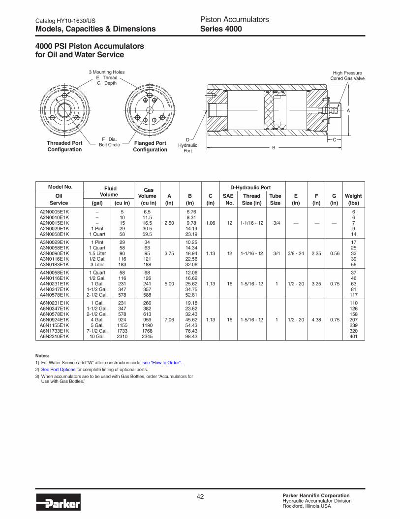
Catalog HY10-1630/US
PagePiston AccumulatorsSeries 4000
42 Parker Hannifin CorporationHydraulic Accumulator DivisionRockford, Illinois USA
Notes:
1) For Water Service add “W” after construction code, see “How to Order”.
2) See Port Options for complete listing of optional ports.
3) When accumulators are to be used with Gas Bottles, order “Accumulators forUse with Gas Bottles.”
Model No. Fluid Gas D-Hydraulic Port
Oil Volume Volume A B C SAE Thread Tube E F G WeightService (gal) (cu in) (cu in) (in) (in) (in) No. Size (in) Size (in) (in) (in) (lbs)
A2N0005E1K – 5 6.5 6.76 6A2N0010E1K – 10 11.5 8.31 6A2N0015E1K – 15 16.5 2.50 9.78 1.06 12 1-1/16 - 12 3/4 — — — 7A2N0029E1K 1 Pint 29 30.5 14.19 9A2N0058E1K 1 Quart 58 59.5 23.19 14
A3N0029E1K 1 Pint 29 34 10.25 17A3N0058E1K 1 Quart 58 63 14.34 25A3N0090E1K 1.5 Liter 90 95 3.75 18.94 1.13 12 1-1/16 - 12 3/4 3/8 - 24 2.25 0.56 33A3N0116E1K 1/2 Gal. 116 121 22.56 39A3N0183E1K 3 Liter 183 188 32.06 56
A4N0058E1K 1 Quart 58 68 12.06 37A4N0116E1K 1/2 Gal. 116 126 16.62 46A4N0231E1K 1 Gal. 231 241 5.00 25.62 1.13 16 1-5/16 - 12 1 1/2 - 20 3.25 0.75 63A4N0347E1K 1-1/2 Gal. 347 357 34.75 81A4N0578E1K 2-1/2 Gal. 578 588 52.81 117
A6N0231E1K 1 Gal. 231 266 19.18 110A6N0347E1K 1-1/2 Gal. 347 382 23.62 126A6N0578E1K 2-1/2 Gal. 578 613 32.43 158A6N0924E1K 4 Gal. 924 959 7.06 45.62 1.13 16 1-5/16 - 12 1 1/2 - 20 4.38 0.75 207A6N1155E1K 5 Gal. 1155 1190 54.43 239A6N1733E1K 7-1/2 Gal. 1733 1768 76.43 320A6N2310E1K 10 Gal. 2310 2345 98.43 401
4000 PSI Piston Accumulatorsfor Oil and Water Service
Models, Capacities & Dimensions
Flanged PortConfiguration
Threaded PortConfiguration
F Dia.Bolt Circle
DHydraulic
Port
3 Mounting HolesE ThreadG Depth
B
C
A
High PressureCored Gas Valve

Catalog HY10-1630/US
PagePiston AccumulatorsSeries 4000
43 Parker Hannifin CorporationHydraulic Accumulator DivisionRockford, Illinois USA
Fluid Gas D Port (Both Ends)Accumulator Volume Volume A B SAE Thread Tube E F G Weight
Model No. (gal) (cu in) (cu in) (in) (in) No. Size (in) Size (in) (in) (in) (lbs)
A4N0058E3KTETE 1 Quart 58 68 11.63 37A4N0116E3KTETE 1/2 Gal. 116 126 16.19 46A4N0231E3KTETE 1 Gal. 231 241 5.00 25.19 16 1-5/16 - 12 1 1/2 - 20 3.25 0.75 63A4N0347E3KTETE 1-1/2 Gal. 347 357 34.31 81A4N0578E3KTETE 2-1/2 Gal. 578 588 52.38 117
A6N0231E3KTETE 1 Gal. 231 266 17.38 110A6N0347E3KTETE 1-1/2 Gal. 347 382 21.81 126A6N0578E3KTETE 2-1/2 Gal. 578 613 30.63 158A6N0924E3KTETE 4 Gal. 924 959 7.06 43.81 16 1-5/16 - 12 1 1/2 - 20 4.38 0.75 207A6N1155E3KTETE 5 Gal. 1155 1190 52.63 239A6N1733E3KTETE 7-1/2 Gal. 1733 1768 74.63 320A6N2310E3KTETE 10 Gal. 2310 2345 96.63 401
4000 PSI Piston Accumulators for Use with Gas Bottles
Model No. Gas Volume D Port
Gas Nominal Actual A B C SAE Thread Tube E F G Weight Bottle (gal) (cu in) (in) (in) (in) No. Size (in) Size (in) (in) (in) (lbs)
B4N0058E1K 1 Quart 86 12.06 35B4N0116E1K 1/2 Gal. 144 16.62 44B4N0231E1K 1 Gal. 259 5.00 25.62 1.13 16 1-5/16 - 12 1 1/2 - 20 3.25 0.75 62B4N0347E1K 1-1/2 Gal. 375 34.75 80B4N0578E1K 2-1/2 Gal. 606 52.81 115
B6N0231E1K 1 Gal. 319 19.18 105B6N0347E1K 1-1/2 Gal. 435 23.62 121B6N0578E1K 2-1/2 Gal. 666 32.43 153B6N0942E1K 4 Gal. 1012 7.06 45.62 1.13 16 1-5/16 - 12 1 1/2 - 20 4.38 0.75 202B6N1155E1K 5 Gal. 1243 54.43 234B6N1733E1K 7-1/2 Gal. 1821 76.43 315B6N2310E1K 10 Gal. 2398 98.43 396
Models, Capacities & Dimensions
4000 PSI Auxiliary Gas Bottles
Threaded PortConfiguration
Flange PortConfiguration
F Dia.Bolt Circle D
HydraulicPort
3 Mounting HolesE ThreadG Depth
B
C
A
High PressureCored Gas Valve
Threaded PortConfiguration
Flange PortConfiguration
F Dia.Bolt Circle D
HydraulicPort
3 Mounting HolesE ThreadG Depth
DGas Port
A
B
Typical Both Ends

Catalog HY10-1630/US
PagePiston AccumulatorsSeries 4000
44 Parker Hannifin CorporationHydraulic Accumulator DivisionRockford, Illinois USA
Model No. Fluid Gas D-Hydraulic Port
Oil Volume Volume A B C BSPP/G SAE E F G WeightService (Liters) (cu in) (Liters) (mm) (mm) (mm) (in) Flange (mm) (mm) (mm) (Kg)
A2N0005E2K 0.08 5 0.11 172 2.4A2N0010E2K 0.16 10 0.19 211 2.8A2N0015E2K 0.25 15 0.24 64 248 27 3/4 – – – – 3.1A2N0029E2K 0.48 29 0.50 360 4.1A2N0058E2K 0.95 58 0.98 589 6.1
A3N0029E2K 0.48 29 0.56 260 7.8A3N0058E2K 0.95 58 1.03 364 11.1A3N0090E2K 1.47 90 1.56 96 481 29 3/4 – M10 60 15 14.8A3N0116E2K 1.90 116 1.98 573 17.7A3N0183E2K 3.00 183 3.08 814 25.4
A4N0058E2K 0.95 58 1.11 306 16.6A4N0116E2K 1.90 116 2.06 422 20.6A4N0231E2K 3.79 231 3.95 127 651 29 1 – M12 82 18 28.7A4N0347E2K 5.69 347 5.85 883 36.8A4N0578E2K 9.47 578 9.64 1341 53.0
A6N0231E2K 3.79 231 4.36 487 49.8A6N0347E2K 5.69 347 6.26 600 57.2A6N0578E2K 9.47 578 10.00 824 71.9A6N0924E2K 15.10 924 15.70 180 1159 29 1 – M12 110 18 93.9A6N1155E2K 18.90 1155 19.50 1383 109A6N1733E2K 28.40 1733 29.00 1941 145A6N2310E2K 37.90 2310 38.40 2500 182
Notes:
1) For Water Service add “W” after construction code, see “How to Order” .
2) See Port Options for complete listing of optional ports.
3) When accumulators are to be used with Gas Bottles, order “Accumulators forUse with Gas Bottles.”
276 Bar Metric Piston Accumulators for Oil and Water Service
Models, Capacities & Dimensions
Flanged PortConfiguration
Threaded PortConfiguration
F Dia.Bolt Circle
DHydraulic
Port
3 Mounting HolesE ThreadG Depth
B
C
A
High PressureCored Gas Valve

Catalog HY10-1630/US
PagePiston AccumulatorsSeries 4000
45 Parker Hannifin CorporationHydraulic Accumulator DivisionRockford, Illinois USA
276 Bar Metric Piston Accumulators for Use with Gas Bottles
276 Bar Metric Auxiliary Gas Bottles
Model No. Gas Volume D-Hydraulic Port
Gas Nominal Actual A B C BSPP/G SAE E F G WeightBottle (liters) (liters) (mm) (mm) (mm) (in) Flange (mm) (mm) (mm) (Kg)
B4N0058E2K 0.95 1.41 267 15.8B4N0116E2K 1.90 2.36 383 19.9B4N0231E2K 3.79 4.24 121 611 29 1 – M12 82 18 27.9B4N0347E2K 5.69 6.15 843 36.1B4N0578E2K 9.47 9.93 1302 52.2
B6N0231E2K 3.79 5.23 413 47.5B6N0347E2K 5.69 7.13 525 54.9B6N0578E2K 9.47 10.90 749 69.6B6N0924E2K 15.10 16.60 175 1084 29 1 – M12 110 18 91.6B6N1155E2K 18.90 20.40 1308 106B6N1733E2K 28.40 29.80 1867 143B6N2310E2K 37.90 39.30 2426 180
Fluid GasD - Port (Both Ends)
Accumulator Volume Volume A B BSPP/G SAE E F G WeightModel No. (Liters) (cu in) (Liters) (mm) (mm) (in) Flange (mm) (mm) (mm) (Kg)
A4N0058E2KRDRD 0.95 58 1.11 267 16.6A4N0116E2KRDRD 1.90 116 2.06 383 20.6A4N0231E2KRDRD 3.79 231 3.95 121 611 1 – M12 82 18 28.7A4N0347E2KRDRD 5.69 347 5.85 843 36.8A4N0578E2KRDRD 9.47 578 9.64 1302 53.0
A6N0231E2KRDRD 3.79 231 4.36 413 49.8A6N0347E2KRDRD 5.69 347 6.26 525 57.2A6N0578E2KRDRD 9.47 578 10.00 749 71.9A6N0924E2KRDRD 15.10 924 15.70 175 1084 1 – M12 110 18 93.9A6N1155E2KRDRD 18.90 1155 19.50 1308 109A6N1733E2KRDRD 28.40 1733 29.00 1867 145A6N2310E2KRDRD 37.90 2310 38.40 2426 182
Models, Capacities, Dimensions
Threaded PortConfiguration
Flange PortConfiguration
F Dia.Bolt Circle D
HydraulicPort
3 Mounting HolesE ThreadG Depth
B
C
A
High PressureCored Gas Valve
Threaded PortConfiguration
Flange PortConfiguration
F Dia.Bolt Circle D
HydraulicPort
3 Mounting HolesE ThreadG Depth
DGas Port
A
B
Typical Both Ends

Catalog HY10-1630/US
PagePiston AccumulatorsSeries 4000
46 Parker Hannifin CorporationHydraulic Accumulator DivisionRockford, Illinois USA
Flange Size SAE Flange Dimensions (in.) Metric ISO 6162 Flange Dimensions (mm)in mm A B C F G A B C F G
1½" 38 5/8 - 11 1.438 3.125 1½ 1.375 M16 36.5 79.4 38 34.9
2" 50 3/4 - 10 1.750 3.812 2 1.500 M20 44.5 96.8 50 38.1
2½" — 7/8 - 9 2.312 4.875 2½ 1.625 — — — — —
SAE Straight Thd. Code 62 Flange NPT BSPP ISO 6149-1Port Port Min. Port Port Code Min. Port Port Min. Port Port Min. Port Port Min.Size Code Bore Size Inch Metric Bore Size Code Bore Size Code Bore Size Code Bore #5 TA 2" 1" PG MG 4" 3/8" UT 2" 3/8" RA 2" M14 YA 2"
#6 TB 2" 1¼" PH MH 4" 1/2" UU 2" 1/2" RB 2" M18 YB 2"
#8 TC 2" 1½" PP MV 6" 3/4" UV 2" 3/4" RC 2" M22 YC 2"
#10 TI 2" 2" PQ MQ 6" 1" UW 3" 1" RD 3" M27 YD 2"
#12 TD 2" — — — — 1¼" UX 3" 1¼" RE 3" M33 YE 3"
#16 TE 3" — — — — 1½" UY 4" 1½" RF 4" M42 YF 3"
— — — — — — — 2” UZ 4” 2” RG 4” — — —
Optional PortsThe following ports are available as options on all piston accumulators.
Notes:1) 1" thru 2" flanges are to standard SAE Code 62 dimensions, 2-1/2" to “Socket Weld Flange Adapter Pattern”, dimensions are shown below.
Metric pattern supplied on 276 Bar Metric units unless otherwise specified.2) BSPT and Metric ports available, consult factory.
SAE 4-Bolt Flange DimensionsCode 62 (ISO 6162) (thru 2" diameter) – 6000 PSI (410 Bar)
Gas Valve Option (M)A heavy duty (military style) poppet-type gas valve cartridge (Mil.Spec. MS28889-2) is available as an option (M) – specify whenordering.
Military Style(MS)
Gas Valve
Options
C
B
F
A (4 places) xG Min. Depth
1/2–20 UNF-2A

Catalog HY10-1630/US
PagePiston AccumulatorsSeries 4000
47 Parker Hannifin CorporationHydraulic Accumulator DivisionRockford, Illinois USA
Description Part NumberSafety Fuse Assembly1 086471xxxx
Replacement Rupture Disks 756003xxxx
Fuse Adapter 1468970002
1) Assembly includes housing and rupture disk, xxxx =pressure setting in 100 psi increments, i.e., for an assemblywith a 2000 PSI setting, order P/N 0864712000.
Safety Fuse Options (F)Safety Fuses are used as a safety device on accumulatorsand gas bottles to prevent over-pressurization of gas due toexternal heat or hydraulic pressure (set at 140% of maxi-mum system pressure to avoid rupture disk fatigue andpremature failure). The rupture disks are calibrated torupture at a pre-determined pressure. Safety fuses areavailable on most sizes of piston accumulators. Safety fusescan be installed on all piston accumulators by using a fuseadapter. 4" bore units and above can be equipped with afuse port machined in the gas cap by specifying the “SafetyFuse Option” (F) at the time of order in the model code, see“How to Order.” The safety fuse assembly and/or fuseadapter must be ordered separately.
1.25#8 SAEStraightPort Th’d
#5 SAEStraightPort Th’d
#5 SAEStraightPort Th’d0.48
3.77
Fuse Adapter
1.44
0.950.70
1.55
Fuse
#8 SAE3/4-16 UNF-2A
Recommended MaximumSeal Operating Temperature with General ApplicationCode Polymer Temperature Range Reduced Life and Compatibility*
KBuna -20°F to 165°F 200°F Parker's Standard Compound – CompatibleNitrile -29°C to 74°C 93°C with most mineral oil-based fluids
EFluorocarbon -10°F to 250°F 400°F Compatible with most mineral oil-based fluids at
Elastomer -23°C to 121°C 204°C higher temperatures and some exotic fluids
DEthylene -40°F to 250°F 300°F Compatible with most phosphate ester fluids
Propylene -40°C to 121°C 149°C and some synthetic fluids
HHydrogenated -45°F to 325°F 350°F Compatible with most oil-based and biodegradable fluids,
Nitrile -43°C to 162°C 177°C maintains sealing effectiveness at a wide range of temperatures
QLow Temp. -45°F to 185°F 200°F Compatible with most mineral oil-based fluids and
Nitrile -43°C to 85°C 93°C maintains sealing effectiveness at low temperatures
*Note: Consult local distributor or factory for fluid compatibility information. Temperature ranges may vary depending upon fluid used in hydraulic system.
Seal Material Options
Water Service Option (W)Piston accumulators are available for use with water as the fluid media. Modifications include electroless nickel plating all surfacesand metal parts.
Options

Catalog HY10-1630/US
PagePiston AccumulatorsSeries 4000
48 Parker Hannifin CorporationHydraulic Accumulator DivisionRockford, Illinois USA
Parts List — Hydraulic Accumulators
Item Part Description
1 Body2 Hydraulic Cap3 Gas Cap4 Piston5 V-O-Ring5A V-O-Ring Back-Up Washers6 PTFE Ring (Piston)7 O-Ring7A O-Ring Back-Up Washer8 Gas Valve w/High Pressure Core8A Gas Valve O-Ring9 Gas Valve Guard9A Screw
4000 PSI Seal Kit Numbers (Includes items 5, 5A, 6, 7, 7A, 8A)
Material Bore Size
2" 3" 4" 6"Buna-Nitrile (Std.) RK0200K000 RK0300K000 RK0400K000 RK0600K000Fluorocarbon RK0200E000 RK0300E000 RK0400E000 RK0600E000EPR RK0200D000 RK0300D000 RK0400D000 RK0600D000Hydrogenated Nitrile RK0200H000 RK0300H000 RK0400H000 RK0600H000Low Temp Nitrile RK0200Q000 RK0300Q000 RK0400Q000 RK0600Q000
Parts
Mounting, Charging & GaugingAccessoriesParker offers a wide variety of mounting, charging andgauging accessories. See “Accumulator Accessories.”
Special OptionsIf your application requires a piston accumulator, gas bottle, orspecial option that falls outside of Parker’s broad offering,consult your local distributor, Parker representative, or thefactory with your specific requirements. Parker has themanufacturing and engineering expertise to design and buildpiston accumulators to your exacting requirements, fromsimple modifications of standard units to complete designs.Some example of Parker’s past special designs include:
• Special and Stainless Steel Materials• Piston Position and Velocity Sensors and Switches• Special Seals• Non-Standard Capacities• Tie Rod Construction• Special Certifications• Spring & Weight Loaded
Consult the experts at Parker with your next piston accumulator requirement!

Catalog HY10-1630/US
PagePiston AccumulatorsSeries 4000
49 Parker Hannifin CorporationHydraulic Accumulator DivisionRockford, Illinois USA
Hydraulic and Gas Port Modifications Designated by 2 Digits
1st 2nd Min. Digit Style Digit Description Bore Size
Blank Std. Blank Std.T SAE A SAE #5 (1/2 - 20) 2”
Straight B SAE #6 (9/16 - 18) 2”Thread C SAE #8 (3/4 - 16) 2”Ports D SAE #12 (1 1/16 - 12) 2”
E SAE #16 (1 5/16 - 12) 3”I SAE #10 (7/8 - 14) 2”6000 PSI (Code 62) Min. Bore
P Flange G 1” 4”Code 62 H 1 1/4” 4”
P 1 1/2” 6”M Metric Q 2” 6”
FlangeperISO 6162
T 3/8” 2”U NPTF U 1/2” 2”
(Not V 3/4” 2” Recommended) W 1” 2”
X 1 1/4” 2”Y 1 1/2” 4”Z 2” 4”BSPP/BSPT Metric/ISO 6149-1
R BSPP A 3/8 - 19 A M14 x 1.5Parallel B 1/2 - 14 B M18 x 1.5
B BSPT C 3/4 - 14 C M22 x 1.5Taper Port D 1 - 11 D M27 x 2
G Metric E 1 1/4 - 11 E M33 x 2Y ISO F 1 1/2 - 11 F M42 x 2
6149-1 G 2 - 11
How to Order Series 4000 Piston AccumulatorsPiston accumulators and gas bottles can be specified by using the symbols in the chart below to develop a model number. Selectonly those symbols that represent the features desired, and place them in the sequence indicated by the example at the top of thechart.
NominalBore Type of Design Design Seal Hyd. Port Gas Port
Series Size Construction Options Capacity Pressure Number Compound Modification Modification
A 4 N – 0231 E 1 K – – – –
Series
A AccumulatorB Gas Bottle
Nominal Bore Size
2 2 inches3 3 inches4 4 inches6 6 inches
Type of Construction
N Threaded both endsnon-ASME materialstandard on 2”, 3”, 4”, 6”
Options
Blank Standard Gas CapW Water ServiceF SAE Fuse Port *G SAE Fuse Port * –
Water ServiceM MS28889-2 Gas ValveL MS28889-2 Gas Valve,
Water ServiceP Fuse* and MS28889-2R Fuse* and MS28889-2,
Water Service
Bore Size/Capacity
0005 5 cu. in. (0.08 liters)0010 10 cu. in. (0.16 liters)0015 2” 15 cu. in. (0.25 liters)0029 29 cu. in. (0.48 liters)0058 58 cu. in. (0.95 liters)0029 29 cu. in. (0.48 liters)0058 58 cu. in. (0.95 liters)0090 3” 90 cu. in. (1.47 liters)0116 116 cu. in. (1.90 liters)0183 183 cu. in. (3.00 liters)0058 58 cu. in. (0.95 liters)0116 116 cu. in. (1.90 liters)0231 4” 1 gal. (3.79 liters)0347 1½ gal. (5.69 liters)0578 2½ gal. (9.47 liters)0231 1 gal. (3.79 liters)0347 1½ gal. (5.69 liters)0578 2½ gal. (9.47 liters)0924 6” 4 gal. (15.1 liters)1155 5 gal. (18.9 liters)1733 7½ gal. (28.4 liters)2310 10 gal. (37.9 liters)
Consult factory for other available sizes.
Design Pressure
E 4000 PSI
Design Number
1 Standard2 Metric Mounting
Holes & Hyd. Port(BSPP Standard)Specify Optional Ports
3 Optional Port(Hyd. or Gas, SeePort Modifications Table)
*** Special Design
Standard Ports Available(See Port Modifications Table if Using
Other Than Standard Ports Shown Below)
Bore 4000 PSI Port SizesSize Standard Metric (BSPP)
2” SAE #12 3/43” SAE #12 3/44” SAE #16 16” SAE #16 1
Seal Compound(See Catalog for
Temperature Settings)
K Buna Nitrile (Std)E FluoroelastomerD EPRH Hydrogenated
NitrileQ Low Temp.S Special Seals
(to be specified)
Example of Optional Port AccumulatorA 4 N 0231 E 3 K T C U V
Non-std.Port
SAE #8Hyd. Port
NPT 3/4” Gas Port
* Safety fuse assembly not included.Order fuse assembly separately.
Ordering Information

Catalog HY10-1630/US
PagePiston AccumulatorsSeries 5000
50 Parker Hannifin CorporationHydraulic Accumulator DivisionRockford, Illinois USA
Series 5000 PistonAccumulators• Heavy Duty Service with 5000 PSI
Operating Pressure
• 2" thru 9" Bores with Over 30
Standard Capacities
• Patented V-O-ring Piston Seals
• Serviceable Threaded End
Construction
• Five Standard Seal Options to
Handle a Variety of Fluids and
Temperatures
• ASME Certification and
CE Marking Available

Catalog HY10-1630/US
PagePiston AccumulatorsSeries 5000
51 Parker Hannifin CorporationHydraulic Accumulator DivisionRockford, Illinois USA
Materials• Shell – high strength alloy steel• Caps – steel• Pistons – aluminum (2" thru 7"), ductile iron (9")• Gas Valve Cartridge – steel• Gas Valve Protector – steel• Piston Glide Rings – PTFE• Piston & End Seals – various polymers• Piston Seal Backups – PTFE
Actual Bore Sizes & Maximum Flow RatesPressure Ratings
Series 5000 piston accumulators are rated at minimum 4 to 1design factors. For pressures over 5000 psi, consult thefactory.
FluidsParker’s piston accumulators are compatible with a widevariety of fluids. Standard accumulators (with nitrile seals) maybe used with petroleum-based industrial oils or water-basedflame resistant fluids. Optional seals compatible with mostindustrial fluids are available with temperature ranges from-45°F to 325°F (-43°C to 162°C).
PrechargeUnits are shipped with a nominal nitrogen precharge asstandard. For specific precharge pressures, specify at the timeof order.
Standard PortsThe following ports are supplied as standard on all fluid endsand on the gas end of accumulators ordered for use with gasbottles:
Nominal Actual Bore Size Max. Recommended Flow*Bore Size (in.) (in.) (mm) GPM LPM
2 2.03 51.4 100 3803 3.00 76.2 220 8344 4.03 102 397 15046 5.78 147 818 30967 7.00 178 1199 45389 9.00 229 1982 7502
*Note: Based on 120 in/sec maximum piston speed, port & fitting sizewill become limiting factors for most applications.
Standard PortsBore Metric ModelsSize Standard Models BSPP Port (in)
2 SAE #12 3/4
3 SAE #12 3/4
4 SAE #16 1
6 SAE #16 1
7 2” Code 62 Flange 2” Metric ISO 6162 Flange
9 2” Code 62 Flange 2” Metric ISO6162 Flange
Available OptionsIf your application requires a piston accumulator, gas bottle, orspecial option that falls outside of Parker’s broad offering,consult your local distributor, Parker representative, or thefactory with your specific requirements. Parker has themanufacturing and engineering expertise to design and buildpiston accumulators to your exacting requirements, fromsimple modifications of standard units to complete designs.Some example of Parker’s past special designs include:
• Special and Stainless Steel Materials• Piston Position and Velocity Sensors and Switches• Special Seals• Non-Standard Capacities• Water Service• Ports• Fixed Gauge Mounts• Fuse Plug Assemblies
Auxiliary Gas BottlesWhen space does not permit the installation of the requiredpiston accumulator, a smaller accumulator may be used byconnecting it to an auxiliary gas bottle(s) that can be locatedin a nearby spot where space is available. In some cases, apiston accumulator and gas bottle combination may be moreeconomical, especially large capacity sizes. Piston travel,confined to the accumulator, must be calculated with amplemargins to store the required fluid.
Gas ValveSeries 5000 accumulators and gas bottles with 2” through 6”bores are supplied with a high pressure cored gas valve asstandard. Models with 7” and 9” bores are supplied with aheavy duty (military) poppet-type gas valve cartridge (Mil.Spec. MS28889-2) as standard.
Military Style (MS)Gas Valve
(7” - 9” Bores)
Specifications
Gas Valve withHigh Pressure Core
(2” - 6” Bores)
Series 5000
#5 SAE THREAD1/2–20 UNF-2A
1/2–20 UNF-2A
Note: The standard Parker gas cap will accept either style gas valve.

Catalog HY10-1630/US
PagePiston AccumulatorsSeries 5000
52 Parker Hannifin CorporationHydraulic Accumulator DivisionRockford, Illinois USA
Model No. Fluid Gas D-Hydraulic Port
Oil Volume Volume A B C SAE Thread Tube E F G WeightService (gal) (cu in) (cu in) (in) (in) (in) No. Size (in) Size (in) (in) (in) (lbs)
A2N0005C1K – 5 6.5 6.76 6A2N0010C1K – 10 11.5 8.31 7A2N0015C1K – 15 16.5 2.63 9.78 1.06 12 1-1/16 - 12 3/4 – – – 8A2N0029C1K 1 Pint 29 30.5 14.19 11A2N0058C1K 1 Quart 58 59.5 23.19 17
A3N0029C1K 1 Pint 29 34 10.25 21A3N0058C1K 1 Quart 58 63 14.34 28A3N0090C1K 1.5 Liter 90 95 4.00 18.94 1.13 12 1-1/16 - 12 3/4 3/8 - 12 2.25 0.56 35A3N0116C1K 1/2 Gal. 116 121 22.56 40A3N0183C1K 3 Liter 183 188 32.06 55
A4N0058C1K 1 Quart 58 68 12.06 43A4N0116C1K 1/2 Gal. 116 126 16.62 54A4N0231C1K 1 Gal. 231 241 5.25 25.62 1.13 16 1-5/16 - 12 1 1/2 - 20 3.25 0.75 77A4N0347C1K 1-1/2 Gal. 347 357 34.75 100A4N0578C1K 2-1/2 Gal. 578 588 52.81 146
A6N0231C1K 1 Gal. 231 266 19.18 128A6N0347C1K 1-1/2 Gal. 347 382 23.62 148A6N0578C1K 2-1/2 Gal. 578 613 32.43 190A6N0924C1K 4 Gal. 924 959 7.50 45.62 1.13 16 1-5/16 - 12 1 1/2 - 20 4.38 0.75 252A6N1155C1K 5 Gal. 1155 1190 54.43 293A6N1733C1K 7-1/2 Gal. 1733 1768 76.43 396A6N2310C1K 10 Gal. 2310 2345 98.43 499
Notes:
1) For Water Service add “W” after construction code, see “How to Order”.
2) See “Port Options” for complete listing of port options.
3) ASME certified and CE marked accumulators and gas bottles available.
5000 PSI Piston Accumulators for Oil and Water Service
Models, Capacities & Dimensions Series 5000 Small Bore
Flanged PortConfiguration
Threaded PortConfiguration
F Dia.Bolt Circle
DHydraulic
Port
3 Mounting HolesE ThreadG Depth
B
C
A
High PressureCored Gas Valve
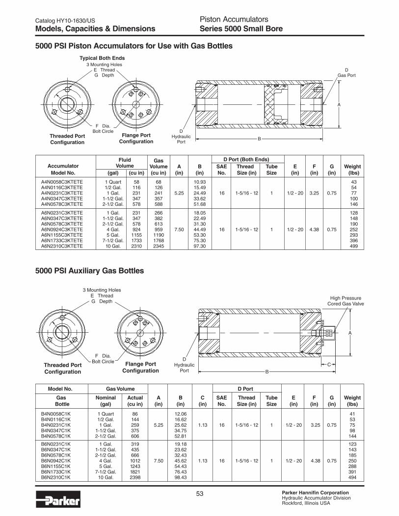
Catalog HY10-1630/US
PagePiston AccumulatorsSeries 5000
53 Parker Hannifin CorporationHydraulic Accumulator DivisionRockford, Illinois USA
Fluid Gas D Port (Both Ends)Accumulator Volume Volume A B SAE Thread Tube E F G Weight
Model No. (gal) (cu in) (cu in) (in) (in) No. Size (in) Size (in) (in) (in) (lbs)
A4N0058C3KTETE 1 Quart 58 68 10.93 43A4N0116C3KTETE 1/2 Gal. 116 126 15.49 54A4N0231C3KTETE 1 Gal. 231 241 5.25 24.49 16 1-5/16 - 12 1 1/2 - 20 3.25 0.75 77A4N0347C3KTETE 1-1/2 Gal. 347 357 33.62 100A4N0578C3KTETE 2-1/2 Gal. 578 588 51.68 146
A6N0231C3KTETE 1 Gal. 231 266 18.05 128A6N0347C3KTETE 1-1/2 Gal. 347 382 22.49 148A6N0578C3KTETE 2-1/2 Gal. 578 613 31.30 190A6N0924C3KTETE 4 Gal. 924 959 7.50 44.49 16 1-5/16 - 12 1 1/2 - 20 4.38 0.75 252A6N1155C3KTETE 5 Gal. 1155 1190 53.30 293A6N1733C3KTETE 7-1/2 Gal. 1733 1768 75.30 396A6N2310C3KTETE 10 Gal. 2310 2345 97.30 499
5000 PSI Piston Accumulators for Use with Gas Bottles
5000 PSI Auxiliary Gas Bottles
Model No. Gas Volume D Port
Gas Nominal Actual A B C SAE Thread Tube E F G Weight Bottle (gal) (cu in) (in) (in) (in) No. Size (in) Size (in) (in) (in) (lbs)
B4N0058C1K 1 Quart 86 12.06 41B4N0116C1K 1/2 Gal. 144 16.62 53B4N0231C1K 1 Gal. 259 5.25 25.62 1.13 16 1-5/16 - 12 1 1/2 - 20 3.25 0.75 75B4N0347C1K 1-1/2 Gal. 375 34.75 98B4N0578C1K 2-1/2 Gal. 606 52.81 144
B6N0231C1K 1 Gal. 319 19.18 123B6N0347C1K 1-1/2 Gal. 435 23.62 143B6N0578C1K 2-1/2 Gal. 666 32.43 185B6N0942C1K 4 Gal. 1012 7.50 45.62 1.13 16 1-5/16 - 12 1 1/2 - 20 4.38 0.75 250B6N1155C1K 5 Gal. 1243 54.43 288B6N1733C1K 7-1/2 Gal. 1821 76.43 391B6N2310C1K 10 Gal. 2398 98.43 494
Models, Capacities & Dimensions Series 5000 Small Bore
Threaded PortConfiguration
Flange PortConfiguration
F Dia.Bolt Circle D
HydraulicPort
3 Mounting HolesE ThreadG Depth
DGas Port
A
B
Typical Both Ends
Threaded PortConfiguration
Flange PortConfiguration
F Dia.Bolt Circle D
HydraulicPort
3 Mounting HolesE ThreadG Depth
B
C
A
High PressureCored Gas Valve

Catalog HY10-1630/US
PagePiston AccumulatorsSeries 5000
54 Parker Hannifin CorporationHydraulic Accumulator DivisionRockford, Illinois USA
Model No. Fluid Gas D-Hydraulic Port
Oil Volume Volume A B C BSPP/G SAE E F G WeightService (Liters) (cu in) (Liters) (mm) (mm) (mm) (in) Flange (mm) (mm) (mm) (Kg)
A2N0005C2K 0.08 5 0.11 172 2.8A2N0010C2K 0.16 10 0.19 211 3.2A2N0015C2K 0.25 15 0.24 67 248 27 3/4 – – – – 3.7A2N0029C2K 0.48 29 0.50 360 5.0A2N0058C2K 0.95 58 0.98 589 7.6
A3N0029C2K 0.48 29 0.56 260 9.6A3N0058C2K 0.95 58 1.03 364 12.5A3N0090C2K 1.47 90 1.56 102 481 29 3/4 – M10 60 15 15.7A3N0116C2K 1.90 116 1.98 573 18.3A3N0183C2K 3.00 183 3.08 814 25.0
A4N0058C2K 0.95 58 1.11 306 19.4A4N0116C2K 1.90 116 2.06 422 24.6A4N0231C2K 3.79 231 3.95 134 651 29 1 – M12 82 18 34.9A4N0347C2K 5.69 347 5.85 883 45.4A4N0578C2K 9.47 578 9.64 1341 66.2
A6N0231C2K 3.79 231 4.36 487 57.9A6N0347C2K 5.69 347 6.26 600 67.3A6N0578C2K 9.47 578 10.00 824 86.0A6N0924C2K 15.10 924 15.70 191 1159 29 1 – M12 110 18 114A6N1155C2K 18.90 1155 19.50 1383 133A6N1733C2K 28.40 1733 29.00 1941 180A6N2310C2K 37.90 2310 38.40 2500 227
Notes:
1) For Water Service add “W” after construction code, see “How to Order”.
2) See “Port Options” for a complete listing of port options.
3) ASME certified and CE marked accumulators and gas bottles are available.
345 Bar Metric Piston Accumulators for Oil and Water Service
Models, Capacities & Dimensions Series 5000 Small Bore
Flanged PortConfiguration
Threaded PortConfiguration
F Dia.Bolt Circle
DHydraulic
Port
3 Mounting HolesE ThreadG Depth
B
C
A
High PressureCored Gas Valve

Catalog HY10-1630/US
PagePiston AccumulatorsSeries 5000
55 Parker Hannifin CorporationHydraulic Accumulator DivisionRockford, Illinois USA
345 Bar Metric Piston Accumulators for Use with Gas Bottles
345 Bar Metric Auxiliary Gas Bottles
Model No. Gas Volume D-Hydraulic Port
Gas Nominal Actual A B C BSPP/G SAE E F G WeightBottle (liters) (liters) (mm) (mm) (mm) (in) Flange (mm) (mm) (mm) (Kg)
B4N0058C2K 0.95 1.11 306 18.6B4N0116C2K 1.90 2.06 422 23.9B4N0231C2K 3.79 3.95 134 651 29 1 – M12 82 18 34.2B4N0347C2K 5.69 5.85 883 44.6B4N0578C2K 9.47 9.64 1341 65.4
B6N0231C2K 3.79 4.36 487 55.6B6N0347C2K 5.69 6.26 600 65.0B6N0578C2K 9.47 10.00 824 83.8B6N0924C2K 15.10 15.70 191 1159 29 1 – M12 110 18 112B6N1155C2K 18.90 19.50 1383 131B6N1733C2K 28.40 29.00 1941 177B6N2310C2K 37.90 38.40 2500 224
Fluid GasD - Port (Both Ends)
Accumulator Volume Volume A B BSPP/G SAE E F G WeightModel No. (Liters) (cu in) (Liters) (mm) (mm) (in) Flange (mm) (mm) (mm) (Kg)
A4N0058C2KRDRD 0.95 58 1.11 277 19.4A4N0116C2KRDRD 1.90 116 2.06 393 24.6A4N0231C2KRDRD 3.79 231 3.95 134 622 1 – M12 82 18 34.9A4N0347C2KRDRD 5.69 347 5.85 854 45.4A4N0578C2KRDRD 9.47 578 9.64 1312 66.2
A6N0231C2KRDRD 3.79 231 4.36 458 57.9A6N0347C2KRDRD 5.69 347 6.26 571 67.3A6N0578C2KRDRD 9.47 578 10.00 795 86.0A6N0924C2KRDRD 15.10 924 15.70 191 1130 1 – M12 110 18 114A6N1155C2KRDRD 18.90 1155 19.50 1354 133A6N1733C2KRDRD 28.40 1733 29.00 1912 180A6N2310C2KRDRD 37.90 2310 38.40 2471 227
Models, Capacities & Dimensions Series 5000 Small Bore
Threaded PortConfiguration
Flange PortConfiguration
F Dia.Bolt Circle D
HydraulicPort
3 Mounting HolesE ThreadG Depth
DGas Port
A
B
Typical Both Ends
Threaded PortConfiguration
Flange PortConfiguration
F Dia.Bolt Circle D
HydraulicPort
3 Mounting HolesE ThreadG Depth
B
C
A
High PressureCored Gas Valve

Catalog HY10-1630/US
PagePiston AccumulatorsSeries 5000
56 Parker Hannifin CorporationHydraulic Accumulator DivisionRockford, Illinois USA
Fluid GasVolume Volume A B C D E F G Weight
Model No. (gal) (cu in) (cu in) (in) (in) (in) Hydraulic Port (in) (in) (in) (lbs)
A7K1155C1K 5 Gal. 1155 1190 42.50 385A7K1733C1K 7-1/2 Gal. 1733 1768 9.09 57.50
1.63 5/8 - 18 5.75 0.94495
A7K2310C1K 10 Gal. 2310 2345 ±0.06 72.50 611A7K3465C1K 15 Gal. 3465 3520 102.50 837
A9K2310C1K 10 Gal. 2310 2400 50.75 831A9K3465C1K 15 Gal. 3465 3555 68.94 1064A9K4620C1K 20 Gal. 4620 4710 11.78 87.12 1.63 3/4-16 7.00 1.13 1298A9K5775C1K 25 Gal. 5775 5865 ±0.09 105.25 1532A9K6930C1K 30 Gal. 6930 7020 123.43 1765
2" SAE Code 62Flange2
2" SAE Code 62Flange2
Notes:
1) For Water Service add “W” after construction code, see “How to Order”.
2) See “Port Options” for a complete listing of port options.
3) ASME certified and CE marked accumulators and gas bottles are available.
5000 PSI Piston Accumulators for Oil and Water Service
Models, Capacities & Dimensions Series 5000 Large Bore
The Minimum Design Metal Temperature (MDMT) for ASME certified piston accumulators presented in this section is 20°F (-7°C).
Threaded PortConfiguration
Flange PortConfiguration
F Dia.Bolt Circle
3 Mounting HolesE ThreadG Depth
DHydraulic
Port B
C
A
High PressureMS28889-2Gas Valve

Catalog HY10-1630/US
PagePiston AccumulatorsSeries 5000
57 Parker Hannifin CorporationHydraulic Accumulator DivisionRockford, Illinois USA
Fluid GasAccumulator Volume Volume A B D E F G Weight
Model No. (gal) (cu in) (cu in) (in) (in) Port (Both Ends) (in) (in) (in) (lbs)
A7K1155C3KPQPQ 5 Gal. 1155 1190 40.87 385A7K1733C3KPQPQ 7-1/2 Gal. 1733 1768 9.09 55.87
2” SAE Code 62 5/8-18 5.75 0.94495
A7K2310C3KPQPQ 10 Gal. 2310 2345 ±0.06 70.87 611A7K3465C3KPQPQ 15 Gal. 3465 3520 100.87 837
A9K2310C3KPQPQ 10 Gal. 2310 2400 49.12 831A9K3465C3KPQPQ 15 Gal. 3465 3555 67.31 1064A9K4620C3KPQPQ 20 Gal. 4620 4710 11.78 85.49 2” SAE Code 62 3/4-16 7.00 1.13 1298A9K5775C3KPQPQ 25 Gal. 5775 5865 ±0.09 103.62 1532A9K6930C3KPQPQ 30 Gal. 6930 7020 121.80 1765
5000 PSI Auxiliary Gas Bottles
Model No. Gas Volume
Gas Nominal Actual A B C D E F G Weight Bottle (gal) (cu in) (in) (in) (in) Hydraulic Ports (in) (in) (in) (lbs)
B7K1155C1K 5 Gal. 1155 42.50 376B7K1733C1K 7-1/2 Gal. 1733 9.09 57.50
1.63 2” SAE Code 62 5/8 - 18 5.75 0.94489
B7K2310C1K 10 Gal. 2310 ±0.06 72.50 602B7K3465C1K 15 Gal. 3465 102.50 828
B9K2310C1K 10 Gal. 2310 50.75 782B9K3465C1K 15 Gal. 3465 68.94 1016B9K4620C1K 20 Gal. 4620 11.78 87.12 1.63 2” SAE Code 62 3/4 - 16 7.00 1.13 1250B9K5775C1K 25 Gal. 5775 ±0.09 105.25 1483B9K6930C1K 30 Gal. 6930 123.43 1717
Models, Capacities & Dimensions
5000 PSI Piston Accumulators for Use with Gas Bottles
Series 5000 Large Bore
Threaded PortConfiguration
Flange PortConfiguration
F Dia.Bolt Circle
DHydraulic
Port
3 Mounting HolesE ThreadG Depth
B
C
A
High PressureMS28889-2Gas Valve
Threaded PortConfiguration
Flange PortConfiguration
F Dia.Bolt Circle D
HydraulicPort
3 Mounting HolesE ThreadG Depth
DGas Port
A
B
Typical Both Ends

Catalog HY10-1630/US
PagePiston AccumulatorsSeries 5000
58 Parker Hannifin CorporationHydraulic Accumulator DivisionRockford, Illinois USA
Fluid GasVolume Volume A B C D E F G Weight
Model No. (Liters) (cu in) (liters) (mm) (mm) (mm) Hydraulic Port (mm) (mm) (mm) (kg)
A7K1155C2K 18.90 1155 19.50 1080 175A7K1733C2K 28.40 1733 29.00 231.1 1461
41 M16 146 24226
A7K2310C2K 37.90 2310 38.40 ±1.5 1842 277A7K3465C2K 56.85 3465 57.75 2604 380
A9K2310C2K 37.90 2310 39.37 1289 377A9K3465C2K 56.85 3465 58.33 1751 2” Metric 483A9K4620C2K 75.80 4620 77.27 299.2 2213 41 SAE Code 62 M19 178 29 589A9K5775C2K 94.75 5775 96.23 ±2.3 2673 Flange2 695A9K6930C2K 113.70 6930 115.18 3135 801
2" MetricSAE Code 62 Flange2
Notes:
1) For Water Service add “W” after construction code, see “How to Order”.
2) See “Port Options” for a complete listing of port options.
3) ASME certified and CE marked accumulators and gas bottles are available.
345 Bar Metric Piston Accumulators for Oil and Water Service
Models, Capacities & Dimensions Series 5000 Large Bore
Threaded PortConfiguration
Flange PortConfiguration
F Dia.Bolt Circle
3 Mounting HolesE ThreadG Depth
DHydraulic
Port B
C
A
High PressureMS28889-2Gas Valve
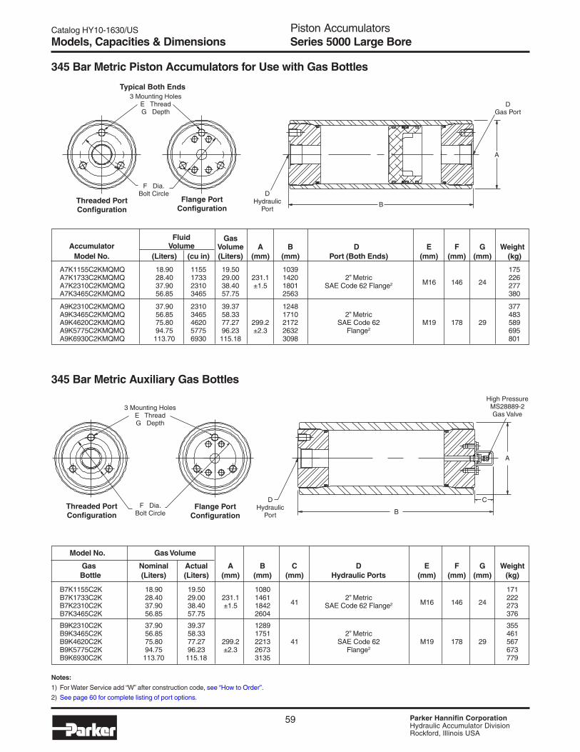
Catalog HY10-1630/US
PagePiston AccumulatorsSeries 5000
59 Parker Hannifin CorporationHydraulic Accumulator DivisionRockford, Illinois USA
Fluid GasAccumulator Volume Volume A B D E F G Weight
Model No. (Liters) (cu in) (Liters) (mm) (mm) Port (Both Ends) (mm) (mm) (mm) (kg)
A7K1155C2KMQMQ 18.90 1155 19.50 1039 175A7K1733C2KMQMQ 28.40 1733 29.00 231.1 1420 2” Metric
M16 146 24226
A7K2310C2KMQMQ 37.90 2310 38.40 ±1.5 1801 SAE Code 62 Flange2 277A7K3465C2KMQMQ 56.85 3465 57.75 2563 380
A9K2310C2KMQMQ 37.90 2310 39.37 1248 377A9K3465C2KMQMQ 56.85 3465 58.33 1710 2” Metric 483A9K4620C2KMQMQ 75.80 4620 77.27 299.2 2172 SAE Code 62 M19 178 29 589A9K5775C2KMQMQ 94.75 5775 96.23 ±2.3 2632 Flange2 695A9K6930C2KMQMQ 113.70 6930 115.18 3098 801
345 Bar Metric Piston Accumulators for Use with Gas Bottles
345 Bar Metric Auxiliary Gas Bottles
Model No. Gas Volume
Gas Nominal Actual A B C D E F G Weight Bottle (Liters) (Liters) (mm) (mm) (mm) Hydraulic Ports (mm) (mm) (mm) (kg)
B7K1155C2K 18.90 19.50 1080 171B7K1733C2K 28.40 29.00 231.1 1461
412” Metric
M16 146 24222
B7K2310C2K 37.90 38.40 ±1.5 1842 SAE Code 62 Flange2 273B7K3465C2K 56.85 57.75 2604 376
B9K2310C2K 37.90 39.37 1289 355B9K3465C2K 56.85 58.33 1751 2” Metric 461B9K4620C2K 75.80 77.27 299.2 2213 41 SAE Code 62 M19 178 29 567B9K5775C2K 94.75 96.23 ±2.3 2673 Flange2 673B9K6930C2K 113.70 115.18 3135 779
Models, Capacities & Dimensions Series 5000 Large Bore
Notes:
1) For Water Service add “W” after construction code, see “How to Order”.
2) See page 60 for complete listing of port options.
Threaded PortConfiguration
Flange PortConfiguration
F Dia.Bolt Circle
DHydraulic
Port
3 Mounting HolesE ThreadG Depth
B
C
A
High PressureMS28889-2Gas Valve
Threaded PortConfiguration
Flange PortConfiguration
F Dia.Bolt Circle D
HydraulicPort
3 Mounting HolesE ThreadG Depth
DGas Port
A
B
Typical Both Ends

Catalog HY10-1630/US
PagePiston AccumulatorsSeries 5000
60 Parker Hannifin CorporationHydraulic Accumulator DivisionRockford, Illinois USA
* Note: Consult local distributor or factory for fluid compatibility information. Temperature ranges may vary depending upon fluid used in hydraulic system.
** The temperature listed indicates the operating temperature range of the seals, not the accumulator. For the Minimum Design Metal Temperature(MDMT) of ASME certified accumulators, refer to page 56.
Seal Material
**Recommended MaximumSeal Operating Temperature with General ApplicationCode Polymer Temperature Range Reduced Life and Compatibility*
KBuna -20°F to 165°F 200°F Parker's Standard Compound – CompatibleNitrile -29°C to 74°C 93°C with most mineral oil-based fluids
EFluorocarbon -10°F to 250°F 400°F Compatible with most mineral oil-based fluids at
Elastomer -23°C to 121°C 204°C higher temperatures and some exotic fluids
DEthylene -40°F to 250°F 300°F Compatible with most phosphate ester fluids
Propylene -40°C to 121°C 149°C and some synthetic fluids
HHydrogenated -45°F to 325°F 350°F Compatible with most oil-based and biodegradable fluids,
Nitrile -43°C to 162°C 177°C maintains sealing effectiveness at a wide range of temperatures
QLow Temp. -45°F to 185°F 200°F Compatible with most mineral oil-based fluids and
Nitrile -43°C to 85°C 93°C maintains sealing effectiveness at low temperatures
Options
Flange Size SAE Flange Dimensions (in.) Metric SAE Flange Dimensions (mm)in mm A B C F G A B C F G
1½" 38 5/8 - 11 1.438 3.125 1½ 1.375 M16 36.5 79.4 38 34.9
2" 50 3/4 - 10 1.750 3.812 2 1.500 M20 44.5 96.8 50 38.1
2½" — 7/8 - 9 2.312 4.875 2½ 1.625 — — — — —
SAE Straight Thd. Code 62 Flange NPT BSPP ISO 6149-1Port Port Min. Port Port Code Min. Port Port Min. Port Port Min. Port Port Min.Size Code Bore Size Inch Metric Bore Size Code Bore Size Code Bore Size Code Bore #5 TA 2" 1" PG MG 4" 3/8" UT 2" 3/8" RA 2" M14 YA 2"
#6 TB 2" 1¼" PH MH 4" 1/2" UU 2" 1/2" RB 2" M18 YB 2"
#8 TC 2" 1½" PP MV 6" 3/4" UV 2" 3/4" RC 2" M22 YC 2"
#10 TI 2" 2" PQ MQ 6" 1" UW 3" 1" RD 3" M27 YD 2"
#12 TD 2" 2½" PR — 7" 1¼" UX 3" 1¼" RE 3" M33 YE 3"
#16 TE 3" 3” PS — 9” 1½" UY 4" 1½" RF 4" M42 YF 3"
— — — — — — — 2” UZ 4” 2” RG 4” — — —
Optional PortsThe following ports are available as options on all piston accumulators.
Notes:1) 1" thru 2" flanges are to standard SAE Code 62 dimensions, 2-1/2" to “Socket Weld Flange Adapter Pattern”, dimensions are shown below.
Metric pattern supplied on 345 Bar Metric units unless otherwise specified.2) BSPT and Metric ports available, consult factory.
SAE 4-Bolt Flange DimensionsCode 62 (ISO 6162) (thru 2" diameter) – 6000 PSI (410 Bar)
C
B
F
A (4 places) xG Min. Depth
Series 5000
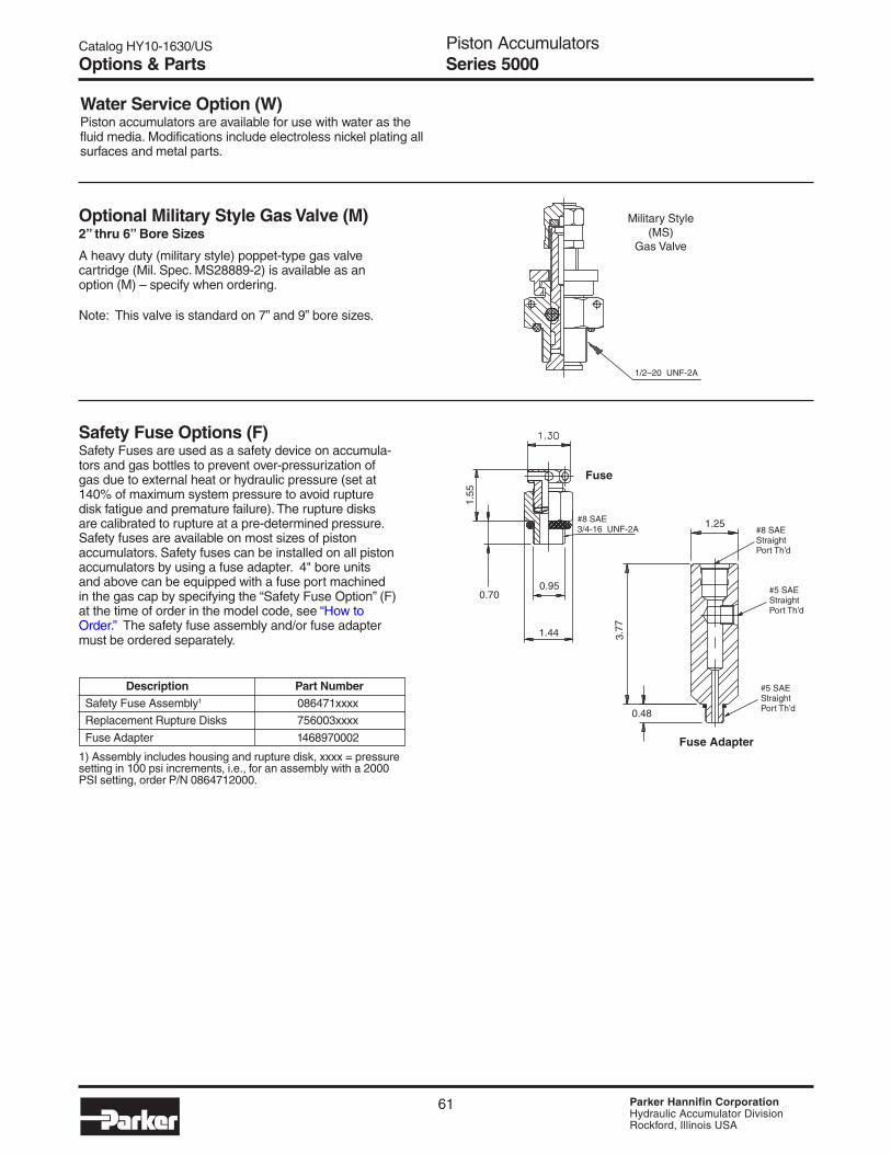
Catalog HY10-1630/US
PagePiston AccumulatorsSeries 5000
61 Parker Hannifin CorporationHydraulic Accumulator DivisionRockford, Illinois USA
Water Service Option (W)Piston accumulators are available for use with water as thefluid media. Modifications include electroless nickel plating allsurfaces and metal parts.
Options & Parts Series 5000
Description Part NumberSafety Fuse Assembly1 086471xxxx
Replacement Rupture Disks 756003xxxx
Fuse Adapter 1468970002
1) Assembly includes housing and rupture disk, xxxx = pressuresetting in 100 psi increments, i.e., for an assembly with a 2000PSI setting, order P/N 0864712000.
Optional Military Style Gas Valve (M)2” thru 6” Bore Sizes
A heavy duty (military style) poppet-type gas valvecartridge (Mil. Spec. MS28889-2) is available as anoption (M) – specify when ordering.
Note: This valve is standard on 7” and 9” bore sizes.
Safety Fuse Options (F)Safety Fuses are used as a safety device on accumula-tors and gas bottles to prevent over-pressurization ofgas due to external heat or hydraulic pressure (set at140% of maximum system pressure to avoid rupturedisk fatigue and premature failure). The rupture disksare calibrated to rupture at a pre-determined pressure.Safety fuses are available on most sizes of pistonaccumulators. Safety fuses can be installed on all pistonaccumulators by using a fuse adapter. 4" bore unitsand above can be equipped with a fuse port machinedin the gas cap by specifying the “Safety Fuse Option” (F)at the time of order in the model code, see “How toOrder.” The safety fuse assembly and/or fuse adaptermust be ordered separately.
Military Style(MS)
Gas Valve
1/2–20 UNF-2A
1.25#8 SAEStraightPort Th’d
#5 SAEStraightPort Th’d
#5 SAEStraightPort Th’d0.48
3.77
Fuse Adapter
1.44
0.950.70
1.55
Fuse
#8 SAE3/4-16 UNF-2A

Catalog HY10-1630/US
PagePiston AccumulatorsSeries 5000
62 Parker Hannifin CorporationHydraulic Accumulator DivisionRockford, Illinois USA
Parts
5000 PSI Seal Kit Numbers (Includes items 5, 5A, 6, 7, 7A, 8A)
Material Bore Size
2" 3” 4" 6" 7" 9"Buna-Nitrile (Std.) RK0200K000 RK0300K000 RK0400K000 RK0600K000 RK0700K000 RK0900K000Fluorocarbon RK0200E000 RK0300E000 RK0400E000 RK0600E000 RK0700E000 RK0900E000EPR RK0200D000 RK0300D000 RK0400D000 RK0600D000 RK0700D000 RK0900D000Hydrogenated Nitrile RK0200H000 RK0300H000 RK0400H000 RK0600H000 RK0700H000 Consult FactoryLow Temp Nitrile RK0200Q000 RK0300Q000 RK0400Q000 RK0600Q000 RK0700Q000 RK0900Q000
Parts List — Hydraulic Accumulators
Item Part Description
1 Body2 Hydraulic Cap3 Gas Cap4 Piston5 V-O-Ring5A V-O-Ring Back-Up Washers6 PTFE Ring (Piston)7 O-Ring7A O-Ring Back-Up Washer8 Gas Valve8A Gas Valve O-Ring9 Gas Valve Guard9A Screw
Series 5000
Mounting, Charging & GaugingAccessoriesParker offers a wide variety of mounting, charging andgauging accessories. See “Accumulator Accessories.”
Special OptionsIf your application requires a piston accumulator, gas bottle, orspecial option that falls outside of Parker’s broad offering,consult your local distributor, Parker representative, or thefactory with your specific requirements. Parker has themanufacturing and engineering expertise to design and buildpiston accumulators to your exacting requirements, fromsimple modifications of standard units to complete designs.Some example of Parker’s past special designs include:
• Special and Stainless Steel Materials• Piston Position and Velocity Sensors and Switches• Special Seals• Non-Standard Capacities• Tie Rod Construction• Special Certifications• Spring & Weight Loaded
Consult the experts at Parker with your next piston accumulator requirement!

Catalog HY10-1630/US
PagePiston AccumulatorsSeries 5000
63 Parker Hannifin CorporationHydraulic Accumulator DivisionRockford, Illinois USA
How to Order Series 5000 Piston AccumulatorsPiston accumulators and gas bottles can be specified by using the symbols in the chart below to develop a model number. Selectonly those symbols that represent the features desired, and place them in the sequence indicated by the example at the top of thechart.
NominalBore Type of Design Design Seal Hyd. Port Gas Port
Series Size Construction Options Capacity Pressure Number Compound Modification Modification
A 7 K – 2310 C 1 K – – – –
Series
A AccumulatorB Gas Bottle
Nominal Bore Size
2 2 inches3 3 inches4 4 inches6 6 inches7 7 inches9 9 inches
Type of Construction
N Threaded both endsnon-ASME mat’l standardon 2”, 3”, 4”, 6”
K Threaded both endsA.S.M.E. mat’l standardon 7” & up
L Same as K with A.S.M.E.approval stamp 7” & up.Available as special onsmaller sizes
E Threaded both ends,CE marked (1 liter andabove) or SEP marked(under 1 liter)
Options
Blank Standard Gas CapW Water ServiceF SAE Fuse Port *G SAE Fuse Port *,
Water ServiceM MS28889-2 Gas ValveL MS 28889-2 Gas Valve,
Water ServiceP Fuse Port* and MS28889-2R Fuse Port* and MS28889-2,
Water Service
Bore Size/Capacity
0005 5 cu. in. (0.08 liters)0010 10 cu. in. (0.16 liters)0015 2” 15 cu. in. (0.25 liters)0029 29 cu. in. (0.48 liters)0058 58 cu. in. (0.95 liters)0029 29 cu. in. (0.48 liters)0058 58 cu. in. (0.95 liters)0090 3” 90 cu. in. (1.47 liters)0116 116 cu. in. (1.90 liters)0183 183 cu. in. (3.00 liters)0058 58 cu. in. (0.95 liters)0116 116 cu. in. (1.90 liters)0231 4” 1 gal. (3.79 liters)0347 1½ gal. (5.69 liters)0578 2½ gal. (9.47 liters)0231 1 gal. (3.79 liters)0347 1½ gal. (5.69 liters)0578 2½ gal. (9.47 liters)0924 6” 4 gal. (15.1 liters)1155 5 gal. ( 18.9 liters)1733 7½ gal. (28.4 liters)2310 10 gal. (37.9 liters)1155 5 gal. (18.9 liters)1733
7”7½ gal. (28.4 liters)
2310 10 gal. (37.9 liters)3465 15 gal. (56.8 liters)2310 10 gal. (37.9 liters)3465 15 gal. (56.8 liters)4620 9” 20 gal. (75.8 liters)5775 25 gal. (94.6 liters)6930 30 gal. (114 liters)
Consult factory for other available sizes.
Design Pressure
C 5000 PSIH 350 Bar (CE marked only)
Design Number
1 Standard Ports2 Metric Mounting
Holes & Hyd. Port(BSPP/Metric FlangeStandard)Specify Optional Ports
3 Optional Port (Hyd. orGas, See PortModifications Table)
*** Special Design
Standard Ports Available(See Port Modifications Table if Using Other
Than Standard Ports Shown Below)
Bore Standard Metric (BSPP)Size Ports Ports
2” SAE #12 3/43” SAE #12 3/44” SAE #16 16” SAE #16 17” 2” Code 62 Flange 2” ISO6162 Flange9” 2” Code 62 Flange 2” ISO6162 Flange
Hydraulic and Gas Port Modifications Designated by 2 Digits
1st 2nd Min. Digit Style Digit Description Bore Size
Blank Std. Blank Std.
T SAE A SAE #5 (1/2 - 20) 2”Straight B SAE #6 (9/16 - 18) 2”Thread C SAE #8 (3/4 - 16) 2”Ports D SAE #12 (1 1/16 - 12) 2”
E SAE #16 (1 5/16 - 12) 3”F SAE #20 (1 5/8 - 12) 3”G SAE #24 (1 7/8 - 12) 4”H SAE #32 (2 1/2 - 12) 7”I SAE #10 (7/8 - 14) 2”6000 PSI (Code 62) Min. Bore
P Flange F 3/4” 4”Code 62 G 1” 4”
H 1 1/4” 4”M Metric P 1 1/2” 6”
Flange Q 2” 6”per R* 2 1/2” 7”ISO 6162 S* 3” 9”
T 3/8” 2”U NPTF U 1/2” 2”
(Not V 3/4” 2” Recommended) W 1” 2”
X 1 1/4” 2”Y 1 1/2” 4”Z 2” 4”BSPP/BSPT Metric/ISO
R BSPP A 3/8 - 19 A M14 x 1.5Parallel B 1/2 - 14 B M18 x 1.5
B BSPT C 3/4 - 14 C M22 x 1.5Taper Port D 1 - 11 D M27 x 2
G Metric E 1 1/4 - 11 E M33 x 2Y ISO F 1 1/2 - 11 F M42 x 2
6149-1 G 2 - 11 G M48 x 2
Seal Compound(See Catalog for
Temperature Settings)
K Buna Nitrile (Std)E FluoroelastomerD EPRH Hydrogenated
NitrileQ Low Temp.S Special
(to be specified)
* Safety fuse assembly not included.Order fuse assembly separately.
Ordering Information Series 5000
* For socketweld flange.Not availablewith metricflange.
Example of Optional Port AccumulatorA 4 N 0231 C 3 K T C U V
Non-std.Port
SAE #8Hyd. Port
NPT 3/4” Gas Port

Catalog HY10-1630/US
PagePiston AccumulatorsSeries 5000
64 Parker Hannifin CorporationHydraulic Accumulator DivisionRockford, Illinois USA
Notes Series 5000

87 Parker Hannifin CorporationHydraulic Accumulator DivisionRockford, Illinois USA
Inline Pulse-Tone™Hydraulic Shock Suppressors
Inline Pulse-Tone™Shock Suppressors Feature:• Three Bladder Polymers for a Wide
Range of Fluids and Temperatures• NPT, BSPP, SAE or Split Flange
Connections• Mounting in Any Position• 3000 PSI Models for Water/Chemical
Service

Catalog HY10-1630/US
PageInline Pulse-Tone™Hydraulic Shock Suppressors
88 Parker Hannifin CorporationHydraulic Accumulator DivisionRockford, Illinois USA
The Patented Construction
Shockand
NoiseIn
QuietOut
NitrogenCharging Valve
Bladder
Inner Chamber with 1/2” Holes
Compressed Coil Spring
Radial Flow Chamber with 1/32” Holes
Bladder
Nitrogen
Oil
Introduction

Catalog HY10-1630/US
Page
89 Parker Hannifin CorporationHydraulic Accumulator DivisionRockford, Illinois USA
Inline Pulse-Tone™Hydraulic Shock Suppressors
An Inline Pulse-Tone suppressor is located as close tothe pump as possible, usually directly at the pumpoutlet, to stop pulsations and noise before they travelthrough the piping and radiate off other structuralcomponents.
Noise pollution is the hottest topic in the hydraulicindustry today. Lab tests show that pump noise levelsare increased by 2-3 dB(A) just by adding 12 feet ofoutlet and return lines. The lines do not generatenoise. They radiate noise when they respond topulsations or vibrations. The pulsations are usuallygenerated by the pump, and the vibrations are radi-ated by large flat machine surfaces.
Not only do hydraulic lines radiate noise, but theyfrequently provide the primary path for propagatingnoise from the pump to components that, in turn,react to the noise and radiate additional sound. Thishelps explain why many pump manufacturers have avery low dB(A) pump rating, but when the pump isinstalled on a power unit, the sound rating is muchhigher.
Introduction
It is almost impossible to forecast how much addi-tional sound the hydraulic lines and surroundingstructure will radiate. This is why many power unitsare enclosed after they have been manufactured andinstalled.
The Inline Pulse-Tone reduces pump pulsations andshock. When you stop pulsation and vibration, youstop the cause of component wear and leakage. Apower unit with an Inline Pulse-Tone installed canoperate at higher RPM with smaller, less expensivecomponents . . . and less noise.
NOTE OF INTEREST: An increase of 2.71 dBdoubles the intensity noise level.
Why Should You Use the Shock Suppressor?
How Does the Work?
As shown in the diagram on the facing page, oilflowing into the Pulse-Tone goes through threedifferent baffles or diffusers. These metal bafflesare designed to convert 1/2” diameter holes to 1/32”diameter holes. The total radial distance throughthese baffles is only 1/4”.
After passing through these holes, pulsations strike anitrogen charged rubber bladder. The bladder deflectseach time it is hit by a pulsation. This slight deflectionof the bladder reduces the shock and noise.
The bladder is usually charged with nitrogen to 50%to 60% of the hydraulic operating pressure. The 1/32”diameter holes in the last baffle are so small that thebladder cannot extrude into them.
The large area of the bladder, its ability to oscillate ata high frequency and the short distance each pulsa-tion has to travel once it enters the unit explain theeffectiveness of the Pulse-Tone.
Selecting a is Easy!
No complex sizing forumla is required. The InlinePulse-Tone hydraulic shock suppressor is sized tomatch your hydraulic line size. There is a unit to fit
every pipe and tube size from 3/8” to 2” with threadedor flanged connections. Models are available for both3000 PSI and 5000 PSI hydraulic system pressures.

Catalog HY10-1630/US
PageInline Pulse-Tone™Hydraulic Shock Suppressors
90 Parker Hannifin CorporationHydraulic Accumulator DivisionRockford, Illinois USA
Features, Advantages, Benefits
Features Advantages Benefits
Reduces pulsations and shockLess component wear and system
Less maintenanceleakage
Better work environment Higher worker morale and productivityReduces noise Eliminates need for sound proofing Lower system costs
Use smaller, higher RPM components Design flexibilitySmaller motor starters
No moving mechanical parts Nothing to break Low maintenance costs
Wide range of port sizesAccommodates both hose and
Ease of installationtube sizes
Flange mountings Allows for installation of larger units Mounting ease and flexibility
Unit is bidirectional. Cannot be installed backwards Ease of installation
Compact size Allows for mounting close to pump Easily added to existing power units
Special materials for water orResists corrosion
Longer life and wider variety ofchemical service applications
Can be supplied with customer Ease and speed of adjusting toShorter installation timespecified precharge system parameters
Short delivery times Eliminates customer inventory Lower operating costs

Catalog HY10-1630/US
Page
91 Parker Hannifin CorporationHydraulic Accumulator DivisionRockford, Illinois USA
Inline Pulse-Tone™Hydraulic Shock Suppressors
Models• 3000 psi rated for oil applications
• 3000 psi Stainless Steel for water andchemical applications
• 5000 psi for high pressure oil applications
Port ConnectionsFour types of hydraulic line connections areavailable:
• NPT pipe connections from 3/8” to 2” pipe
• BSPP connections from 3/8” to 2” pipe
• SAE port connection from 3/8” to 2” tubing
• Split flange connection from 3/4” to 3”
Inline Pulse-Tone units can be ordered with anycombination of ends, such as a split flange one endand a straight thread on the opposite end. Whenordering, specify the type of connection for eachend.
Bladder Materials• Standard material is high temperature HNBR,
-50° to 300°F (-45° to 149°C)
• Fluorocarbon or EPR bladders are available forspecial applications
PrechargeThe unit can be shipped with a nitrogen prechargeequal to 50% of hydraulic system pressure. Checkprecharge every three months to maintain maximumefficiency. (See page 184 for procedures.)
MountingThe Pulse-Tone may be mounted in any position,horizontal or vertical. Since there are no movingparts, either end may be used for inlet or outlet.Split flange mounting makes it possible to break anexisting connection to add the Pulse-Tone betweenthe flanges.
General Information
235 psi
25 psi
40 psi
420 psi
5.55 MSEC, 180 HZ
75 psi
12 psi
Examples of Pulsation ReductionThe examples below show pulsations forpumps at various pressures before and afterinstallation of the Inline Pulse-Tone.
Piston Pump at 4000 psi and 1800 rpm
Piston Pump at 2000 psi and 1800 rpm
Piston Pump at 750 psi and 1200 rpm
Before
After
Before
After
Before
After
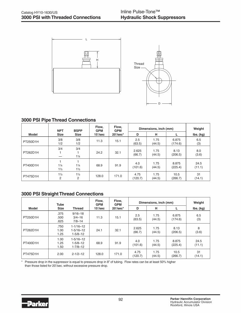
Catalog HY10-1630/US
PageInline Pulse-Tone™Hydraulic Shock Suppressors
92 Parker Hannifin CorporationHydraulic Accumulator DivisionRockford, Illinois USA
3000 PSI with Threaded Connections
3000 PSI Pipe Thread ConnectionsFlow, Flow,
NPT BSPP GPM GPMDimensions, inch (mm) Weight
Model Size Size 15’/sec 20’/sec* D H L lbs. (kg)
PT250D1H3/8 3/8 11.3 15.1 2.5 1.75 6.875 6.51/2 1/2 (63.5) (44.5) (174.6) (3)
3/4 3/42.625 1.75 8.13 8.0PT262D1H 1 1 24.2 32.1(66.7) (44.5) (206.5) (3.6)— 1¼
1 1PT400D1H 1¼ 1¼ 68.9 91.9
4.0 1.75 8.875 24.5
1½ 1½(101.6) (44.5) (225.4) (11.1)
PT475D1H1½ 1½ 128.0 171.0 4.75 1.75 10.5 312 2 (120.7) (44.5) (266.7) (14.1)
3000 PSI Straight Thread ConnectionsFlow, Flow,
Tube GPM GPMDimensions, inch (mm) Weight
Model Size Thread 15’/sec 20’/sec* D H L lbs. (kg)
.375 9/16–18PT250D1H .500 3/4–16 11.3 15.1
2.5 1.75 6.875 6.5
.625 7/8–14(63.5) (44.5) (174.6) (3)
.750 1-1/16–12PT262D1H 1.00 1-5/16–12 24.1 32.1
2.625 1.75 8.13 8
1.25 1-5/8–12(66.7) (44.5) (206.5) (3.6)
1.00 1-5/16–12PT400D1H 1.25 1-5/8–12 68.9 91.9
4.0 1.75 8.875 24.5
1.50 1-7/8–12(101.6) (44.5) (225.4) (11.1)
PT475D1H 2.00 2-1/2–12 128.0 171.04.75 1.75 10.5 31
(120.7) (44.5) (266.7) (14.1)
L
H
D
ThreadSize
* Pressure drop in the suppressor is equal to pressure drop in 8” of tubing. Flow rates can be at least 50% higherthan those listed for 20’/sec. without excessive pressure drop.

Catalog HY10-1630/US
Page
93 Parker Hannifin CorporationHydraulic Accumulator DivisionRockford, Illinois USA
Inline Pulse-Tone™Hydraulic Shock Suppressors
3000 PSI Pipe Thread ConnectionsFlow, Flow,
NPT GPM GPMDimensions, inch (mm)
WeightModel Size 15’/sec 20’/sec* D H L lbs. (kg)
3/4”24.2 32.1
2.625 1.75 8.13 8.0PT262D3H
1” (66.7) (44.5) (206.5) (3.6)
1”PT400D3H 1¼” 68.9 91.9
4.0 1.75 8.875 24.5
1½”(101.6) (44.5) (225.4) (11.1)
3000 PSI Straight Thread ConnectionsFlow, Flow,
Tube GPM GPMDimensions, inch (mm)
WeightModel Size Thread 15’/sec 20’/sec* D H L lbs. (kg)
.750 1-1/16–12PT262D3H 1.00 1-5/16–12 24.1 32.1
2.625 1.75 8.13 8
1.25 1-5/8–12(66.7) (44.5) (206.5) (3.6)
1.00 1-5/16–12PT400D3H 1.25 1-5/8–12 68.9 91.9
4.0 1.75 8.875 24.5
1.50 1-7/8–12(101.6) (44.5) (225.4) (11.1)
L
H
D
ThreadSize
* Pressure drop in the suppressor is equal to pressure drop in 8” of tubing. Flow rates can be at least 50% higherthan those listed for 20’/sec. without excessive pressure drop.
3000 PSI Water/Chemical Service
Cutaway
Three “304” StainlessSteel Chambers
Tube Nickel PlatedInside and Out
“304” Stainless End Pieces
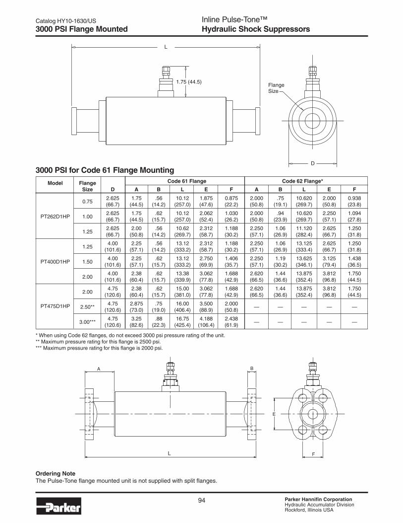
Catalog HY10-1630/US
PageInline Pulse-Tone™Hydraulic Shock Suppressors
94 Parker Hannifin CorporationHydraulic Accumulator DivisionRockford, Illinois USA
3000 PSI for Code 61 Flange Mounting
Model Flange Code 61 Flange Code 62 Flange*
Size D A B L E F A B L E F
0.752.625 1.75 .56 10.12 1.875 0.875 2.000 .75 10.620 2.000 0.938(66.7) (44.5) (14.2) (257.0) (47.6) (22.2) (50.8) (19.1) (269.7) (50.8) (23.8)
PT262D1HP 1.002.625 1.75 .62 10.12 2.062 1.030 2.000 .94 10.620 2.250 1.094(66.7) (44.5) (15.7) (257.0) (52.4) (26.2) (50.8) (23.9) (269.7) (57.1) (27.8)
1.252.625 2.00 .56 10.62 2.312 1.188 2.250 1.06 11.120 2.625 1.250(66.7) (50.8) (14.2) (269.7) (58.7) (30.2) (57.1) (26.9) (282.4) (66.7) (31.8)
1.254.00 2.25 .56 13.12 2.312 1.188 2.250 1.06 13.125 2.625 1.250
(101.6) (57.1) (14.2) (333.2) (58.7) (30.2) (57.1) (26.9) (333.4) (66.7) (31.8)
PT400D1HP 1.504.00 2.25 .62 13.12 2.750 1.406 2.250 1.19 13.625 3.125 1.438
(101.6) (57.1) (15.7) (333.2) (69.9) (35.7) (57.1) (30.2) (346.1) (79.4) (36.5)
2.004.00 2.38 .62 13.38 3.062 1.688 2.620 1.44 13.875 3.812 1.750
(101.6) (60.4) (15.7) (339.9) (77.8) (42.9) (66.5) (36.6) (352.4) (96.8) (44.5)
2.004.75 2.38 .62 15.00 3.062 1.688 2.620 1.44 13.875 3.812 1.750
(120.6) (60.4) (15.7) (381.0) (77.8) (42.9) (66.5) (36.6) (352.4) (96.8) (44.5)
PT475D1HP 2.50**4.75 2.875 .75 16.00 3.500 2.000
— — — — —(120.6) (73.0) (19.0) (406.4) (88.9) (50.8)
3.00***4.75 3.25 .88 16.75 4.188 2.438
— — — — —(120.6) (82.6) (22.3) (425.4) (106.4) (61.9)
* When using Code 62 flanges, do not exceed 3000 psi pressure rating of the unit.** Maximum pressure rating for this flange is 2500 psi.*** Maximum pressure rating for this flange is 2000 psi.
3000 PSI Flange Mounted
D
FlangeSize
1.75 (44.5)
L
Ordering NoteThe Pulse-Tone flange mounted unit is not supplied with split flanges.
A
L
B
E
F

Catalog HY10-1630/US
Page
95 Parker Hannifin CorporationHydraulic Accumulator DivisionRockford, Illinois USA
Inline Pulse-Tone™Hydraulic Shock Suppressors5000 PSI Flange Mounted
5000 PSI for Flange Mounting
Model Flange Code 62 Flange* Dimensions, inch (mm)
Number Size A B D L E F
1.002.000 .94 3.38 10.620 2.250 1.094
PT338C1HP(50.8) (23.9) (85.8) (269.7) (57.2) (27.8)
1.252.250 1.06 3.38 11.120 2.625 1.250(57.2) (26.9) (85.8) (282.4) (66.7) (31.8)
1.252.250 1.06 5.00 13.125 2.625 1.250(57.2) (26.9) (127.0) (333.4) (66.7) (31.8)
PT500C1HP 1.502.500 1.19 5.00 13.625 3.125 1.438(63.5) (30.2) (127.0) (346.1) (79.4) (36.5)
2.002.620 1.44 5.00 13.875 3.812 1.750(66.5) (35.6) (127.0) (352.4) (96.8) (44.5)
FlangeSize
D
L
1.28 (32.5)
Ordering NoteThe Pulse-Tone flange mounted unit is not supplied with split flanges.
A
L
B
E
F

Catalog HY10-1630/US
PageInline Pulse-Tone™Hydraulic Shock Suppressors
96 Parker Hannifin CorporationHydraulic Accumulator DivisionRockford, Illinois USA
5000 PSI Threaded Connection
5000 PSI Straight Thread ConnectionsFor Thread
Tube In Maximum Dimensions, inch (mm)
WeightModel Suppressor Rate Flow D H L lbs. (kg)
.750 1-1/16–12PT338C1H 1.00 1-5/16–12 49 GPM
3.38 1.28 8.13 15
1.25 1-5/8–12(85.8) (32.5) (206.5) (6.36)
1.00 1-5/16–12PT500C1H 1.25 1-5/8–12 150 GPM
5.0 1.28 8.88 48
1.50 1-7/8–12(127.0) (32.5) (225.6) (21.8)
* Pressure drop in unit is equal to pressure drop of 8” of tubing. Flow rates can be at least 50% higher than those listed for 20’/sec withoutexcessive pressure drop.
D
H
L
ThreadSize
Repair KitsRepair kits include a bladder and o-rings. Order by series and seal material.
Series HNBR EPR Fluorocarbon
250 RKPT2500H0 RKPT2500D0 RKPT2500E0
262 & 338 RKPT2620H0 RKPT2620D0 RKPT2620E0
400 & 500 RKPT4000H0 RKPT4000D0 RKPT4000E0
475 RKPT4750H0 RKPT4750D0 RKPT4750E0

Catalog HY10-1630/US
Page
97 Parker Hannifin CorporationHydraulic Accumulator DivisionRockford, Illinois USA
Inline Pulse-Tone™Hydraulic Shock Suppressors
Design
1 Standard3 Water/Chem Service*S Special
* Available in Sizes 262 and 400only.
Ordering Information
How to OrderUse the symbols in the chart below to develop an Inline Pulse-Tone model number. Select only those symbols that representthe features desired and place them in the sequence indicated by the example at the top of the chart.
PT 250 D 1 H – – – – —
Hydraulic Ports* PrechargeSeries Size Pressure Design Seals Type Size Type Size Pressure*
3000 PSI Sizes
250 2.50” Dia.262 2.625” Dia.400 4.00” Dia475 4.75” Dia.
5000 PSI Sizes
338 3.375” Dia.500 5.00” Dia.
Pressure
D 3000 PSIC 5000 PSI
Seals
D EPR*E FluorocarbonH HNBR (STD)
* Not available on 250(2.50”) size.
Port Type Port Size
T SAE B SAE #6 (9/16-18)C SAE #8 (3/4-16)I SAE #10 (7/8-14)D SAE #12 (1-1/16-12)E SAE #16 (1-5/16-12)F SAE #20 (1-5/8-12)G SAE #24 (1-7/8-12)H SAE #32 (2-1/2-12)
U NPT T 3/8”U 1/2”V 3/4”W 1”X 1¼”Y 1½”Z 2”
R BSPP A 3/8”Parallel B 1/2”
C 3/4”D 1”E 1¼”F 1½”G 2”
P Code 61** U 3/4”Split V 1”Flange W 1¼”
J 1½”L 2”M 2½”N 3”
P Code 62** K 3/4”Split G 1”Flange H 1¼”
P 1½”Q 2”
Port AvailabilitySAE
Size #6 #8 #10 #12 #16 #20 #24 #32
250 ● ● ●
262 ■ ■ ■
400 ■ ■ ■
475 ●
338 ● ● ●
500 ● ● ●
Code 61
Size 3/4 1 1¼ 1½ 2 2½ 3
262 ● ● ●
400 ● ● ●
475 ● ◆ ◆◆ Maximum pressure rating for the 2½” flange is 2500 PSI.
Maximum pressure rating for the 3” flange is 2000 PSI.
Flange Availability
Precharge Pressure*
If desired, indicatepressure in psi.If not desired,leave blank.
* Provided at additionalcost.
NPT/BSPP
Size 3/8 1/2 3/4 1 1¼ 1½ 2
250 ● ●
262 ■ ■ ▲
400 ■ ■ ■
475 ● ●
338 ▲ ▲ ▲
500 ▲ ▲ ▲
Code 62
Size 3/4 1 1¼ 1½ 2
338 ● ● ●
500 ● ● ●
▲ BSPP only■ Available for
Water/ChemicalService
* Different type and size hydraulic ports may beordered for each end. Specify left hand portfirst if ports are not the same.
**When ordering different flange port sizes,specify port that connects to the pump first.

Catalog HY10-1630/US
PageInline Pulse-Tone™Hydraulic Shock Suppressors
98 Parker Hannifin CorporationHydraulic Accumulator DivisionRockford, Illinois USA
Charging & Gauging AssembliesIncludes 10 ft. charging hose with standard right-hand threadnitrogen fittings, adapter incorporating gas valve, bleedervalve and gas chuck and gauge.
For 3000 PSI144595 300C (Std)144596 300C (Left Hand Thread)
For 5000 PSI144912 600C
Part Number Pressure Range087040 1000 0 - 1000 PSI
087040 2000 0 - 2000 PSI
087040 3000 0 - 3000 PSI
087040 4000 0 - 4000 PSI
087040 5000 0 - 5000 PSI
087040 6000 0 - 6000 PSI
GaugesGauges may be ordered separately. Listed beloware 2½" dial type pressure gauges with 100 PSIgraduation. Include blowout safety case andorifice surge damper.
Charging & Gauging Assemblies aresold in plastic carrying case.
Charging and Gauging Accessories

Catalog HY10-1630/US
Page
99 Parker Hannifin CorporationHydraulic Accumulator DivisionRockford, Illinois USA
Inline Pulse-Tone™Hydraulic Shock SuppressorsAccessories & Spare Parts
Mounting Clamps
Z Width
∅L (2)
.13
Typ.
HC
Ref
.
.24
DRubberSleeve
AB
Part Dimensions, inch (mm)
Series No. A B C D H ∅∅∅∅∅L Z
252 87001102524.25 3.35 4.42 2.62/2.82 1.64 0.37 x 0.50 1.25
(107.9) (85.1) (112.3) (66.5/71.6) (41.7) (9.4 x 12.7) (31.8)
338 87001103585.00 3.94 5.62 3.25/3.50 2.28 0.37 x 0.50 1.25(127) (100.1) (142.7) (82.6/88.9) (57.9) (9.4 x 12.7) (31.8)
400 87001104135.25 4.33 6.06 3.84/4.11 2.45 0.37 x 0.50 1.25
(133.4) (109.2) (153.9) (97.5/104.1) (62.2) (9.4 x 12.7) (31.8)
475 87001104765.25 4.33 6.71 4.67/4.90 2.77 0.37 x 0.50 1.25
(133.4) (109.2) (170.4) (118.6/124.5) (70.3) (9.4 x 12.7) (31.8)
500 87001105355.75 4.92 7.43 5.02/5.32 3.21 0.37 x 0.50 1.25
(146.1) (125.0) (188.7) (127.5/135.1) (81.5) (9.4 x 12.7) (31.8)
Clamp Dimensions

Catalog HY10-1630/US
PageInline Pulse-Tone™Hydraulic Shock Suppressors
100 Parker Hannifin CorporationHydraulic Accumulator DivisionRockford, Illinois USA
Notes

105 Parker Hannifin CorporationHydraulic Accumulator DivisionRockford, Illinois USA
Accumulator Accessories• Charging & Gauging Assemblies• Unloading Valves• Mounting Kits• Port Adapters• Repair Tools
Accessories for:• Piston Accumulators
• Bladder Accumulators
• Diaphragm Accumulators
• Gas Bottles
• SurgeKushons
• PulseTones

Hydraulic AccumulatorsAccumulator Accessories
106 Parker Hannifin CorporationHydraulic Accumulator DivisionRockford, Illinois USA
Catalog HY10-1630/US
Charging & Gauging AssembliesCharging and Gauging Assembly consists of 10' charging hose with standard right-hand thread nitrogen fittings, adapterincorporating gas valve, bleeder valve and gas chuck. Assemblies are packed in a plastic storage case. Gauge not included.
3000 PSI Charging & Gauging Assemblies (with 3000 PSI Gauge)Part Piston Bladder Diaphragm
Number Style Style Style
144595 3000 All All* with Cored valve
144596 3000 All All* with Cored valve
148675 3000 — — with M28 valve
087100 3000 — 1-15 gal.** —
087102 3000 — 10-150 CI** —
4000/5000 PSI Charging & Gauging Assemblies (with 5000 PSI Gauge)870816 5000 All All —
* For top repairable styles, valve extensionpart #085434 0000 would be required.
Part Number Pressure Range087040 1000 0 - 1000 PSI
087040 2000 0 - 2000 PSI
087040 3000 0 - 3000 PSI
087040 4000 0 - 4000 PSI
087040 6000 0 - 6000 PSI
144595 0000 (Std)144596 0000 (Left Hand Thread)
087100 0000
148675 0000 870816 0000
085434 0000
** Used primarily for top repairable accumulators and/or permanent mount gage.
GaugesGauges are 2½" dial type pressure gauges with 100 PSIgraduation. Include blowout safety case and orifice surgedamper.
Assemblies Packed in Carrying Case
Charging and Gauging Assemblies

107 Parker Hannifin CorporationHydraulic Accumulator DivisionRockford, Illinois USA
Catalog HY10-1630/US Hydraulic AccumulatorsAccumulator Accessories
The following assemblies and partsare recommended for use on all3000 PSI Piston Accumulators and3000 PSI Bottom RepairableBladder Accumulators. Can beused with 3000 PSI Top RepairableAccumulators, but require a GasValve Extension.
NOTE: Can be used on allaccumulators with a gas prechargeless than 3000 PSI. Consult factoryfor further information.
NOTE: These assemblies are notrecommended for continuousmonitoring of gas precharge. Forcontinuous monitoring, see GaugingAdapters.
Item Part Number Description1-10 1445950000 Standard Assembly with Right Hand (RH) Nitrogen Bottle Connection, No Gauge
1-11 1445950500 Standard Assembly RH Connection with 500 PSI Gauge
1-11 1445951000 Standard Assembly RH Connection with 1000 PSI Gauge
1-11 1445952000 Standard Assembly RH Connection with 2000 PSI Gauge
1-11 1445953000 Standard Assembly RH Connection with 3000 PSI Gauge
1-10L 1445960000 Optional Assembly with Left Hand (LH) Nitrogen Bottle Connection, No Gauge
1-5 0851220000 Gauging Assembly, No Hose or Gauge
1-5H 5420880000 Optional Gauging assembly w/ 2" Hose Ext. between Gas Chuck (5) and Adapter Cross (1), No Hose or Gauge
6-10 1457810000 Hose Assembly with RH Connection
6-10L 1457820000 Hose Assembly with LH Connection
1 5420910000 Adapter Cross
2 5420920000 Gas Valve with 1/8" NPT
3 0832140000 Bleeder Valve
5* 5422150000 Gas Chuck
6** 5420860000 Hose Coupling with Female Thread Connection
7 0870520000 Charging Hose
9 6661250000 Nitrogen Bottle Nut with RH Connection
9L 6661260000 Nitrogen Bottle Nut with LH Connection
10 6661240000 Nitrogen Bottle Nipple
11 See Gauges 2.5" Pressure Gauge
0854340000 Gas Valve Extension
1333290000 Case with Insert for Complete Charging and Gauging Assembly
* 5824390000 Gasket for 5422150000 (5)
** 8702770000 Gasket for 5420860000 (6)
2 1/2 IN. PRESSURE GAUGE
1/8 EXT. PIPE THD.
.305–32 EXT. THD.
1/8 EXT. PIPE THD.
NITROGEN BOTTLECONNECTION.960–14 R.H. THD.1/4 FEMALE EXT. PIPE THD.
VIEW AA
.305–32 UNS
1/4 EXT.PIPE THREAD
Charging and Gauging Assemblies

Hydraulic AccumulatorsAccumulator Accessories
108 Parker Hannifin CorporationHydraulic Accumulator DivisionRockford, Illinois USA
Catalog HY10-1630/US
The following assemblies and partsare recommended for use on all3000 PSI Bladder Accumulators.Cannot be used with PistonAccumulators.
NOTE: These assemblies are notrecommended for continuousmonitoring of gas precharge.For continuous monitoring, seeGauging Adapters.
Item Part Number Description1-10 0871020000 Standard Assembly for 10 to 150 Cubic Inch with RH Nitrogen Bottle Connection, No Gauge
1-11 0871021000 Standard Assembly for 10 to 150 Cubic Inch with RH Connection with 1000 PSI Gauge
1-11 0871022000 Standard Assembly for 10 to 150 Cubic Inch with RH Connection with 2000 PSI Gauge
1-11 0871023000 Standard Assembly for 10 to 150 Cubic Inch with RH Connection with 3000 PSI Gauge
1-10 0871000000 Standard Assembly for 1 to 15 Gallon with RH Nitrogen Bottle Connection, No Gauge
1-11 0871001000 Standard Assembly for 1 to 15 Gallon with RH Connection with 1000 PSI Gauge
1-11 0871002000 Standard Assembly for 1 to 15 Gallon with RH Connection with 2000 PSI Gauge
1-11 0871003000 Standard Assembly for 1 to 15 Gallon with RH Connection with 3000 PSI Gauge
1S-5 0871030000 Gauging Assembly for 10 to 150 Cubic Inch (No Hose or Gauge)
1-5 0871010000 Gauging Assembly for 1to 15 Gallon (No Hose or Gauge)
6-10 1457810000 Hose Assembly with RH Connection
1S 4000450000 Gas Chuck Body for 10 to 150 Cubic Inch
1 4017740000 Gas Chuck Body for 1 to 15 Gallon
2 5420920000 Gas Valve with 1/8" NPT
3 0832140000 Bleeder Valve
6* 5420860000 Hose Coupling with 0.305-32 Female Thread Connection
7 0870520000 Charging Hose
9 6661250000 Nitrogen Bottle Nut with RH Connection
10 6661240000 Nitrogen Bottle Nipple
11 See Gauges 2.5" Pressure Gauge
* 8702770000 Gasket for 5420860000 (6)
1353290000 Case with Insert for Complete Charging and Gauging Assembly
1/8 EXT. PIPE THD.
2 1/2 IN.PRESSURE GAUGE
1/8 EXT. PIPE THD.
.305-32 EXT. THD.
1/4 EXT. PIPE THD.
1/4 FEMALE EXT. PIPE THD.
NITROGEN BOTTLECONNECTION.960-14 R.H. THD.
5/8-18 UNF-2B10 CI – 150 CI
7/8-14 UNF-2B1 – 15 GALLON
Charging and Gauging Assemblies

109 Parker Hannifin CorporationHydraulic Accumulator DivisionRockford, Illinois USA
Catalog HY10-1630/US Hydraulic AccumulatorsAccumulator Accessories
Access
ori
es
Item Part Number Description1-8 8708160000 Standard Assembly with Left Hand (LH) Connection, No Gauge
1-9 8708165000 Standard Assembly LH Connection with 5000 PSI Gauge
1-9 8708166000 Standard Assembly LH Connection with 6000 PSI Gauge
1-4 8713720000 Gauging Assembly (No Hose or Gauge)
5-8 8712640000 Hose Assembly with LH Connection
1 8708460000 Adapter Cross
2 L07688000K Gas Valve Assembly
3 8708140000 Bleed Valve
4 8708150000 Gas Chuck
5 0854210000 Valve Connector
6 0854220000 Nitrogen Bottle Nut with LH Connection
7 0854250000 Gas Tank Nipple (Cga 677)
8 0854150000 Charging Hose (10 ft.)
9 See Gauges 2.5" Pressure Gauge
The following assemblies and parts are recommended for useon all 5000 PSI Piston Accumulators and all 5000 PSI BladderAccumulators. 5000 PSI Top Repairable Accumulatorsrequire a Gas Valve Extension.
NOTE: Can be used on all accumulators with a gasprecharge less than 5000 PSI. Consult factory for furtherinformation.
NOTE: These assemblies are not recommended forcontinuous monitoring of gas precharge.For continuous monitoring, see Gauging Adapters.
Charging and Gauging Assemblies
2 1/2 IN. PRESSURE GAUGE
.305–32 EXT. THD.
1/8 EXT. PIPE THD.
1/4 EXT. PIPE THD.
1.035–14 L.H. FEMALE TH’D
.305–32 FEMALE TH’D

Hydraulic AccumulatorsAccumulator Accessories
110 Parker Hannifin CorporationHydraulic Accumulator DivisionRockford, Illinois USA
Catalog HY10-1630/US
Item Part Number Description1-10 1486750000 Standard Assembly with Right Hand (RH) Nitrogen Bottle Connection, No Gauge
1-11 1486751000 Standard Assembly RH Connection with 1000 PSI Gauge
1-11 1486752000 Standard Assembly RH Connection with 2000 PSI Gauge
1-11 1486753000 Standard Assembly RH Connection with 3000 PSI Gauge
1-11 1456755000 Standard Assembly RH Connection with 5000 PSI Gauge
1-10L 8700430000 Optional Assembly with Left Hand (LH) Nitrogen Bottle Connection, No Gauge
1-4 8702780000 Gauging Assembly (No Hose or Gauge)
6-10 1457810000 Hose Assembly with RH Connection
6-10L 1457820000 Hose Assembly with LH Connection
1
2 5420920000 Gas Valve with 1/8" NPT
3 0832140000 Bleeder Valve
4 0873930000 Reducer – 1/4 x 1/8
6* 5420860000 Swivel Connector with Female Thread Connection
7 0870520000 Charging Hose
9 6661250000 Nitrogen Bottle Nut with RH Connection (Cga584)
9L 6661260000 Nitrogen Bottle Nut with LH Connection (Dga 584)
10 6661240000 Nitrogen Bottle Nipple
11 See Gauges 2.5" Pressure Gauge
* 8702770000 Gasket for 5420860000 (6)
1353290000 Case with Insert for Complete Charging and Gauging Assembly
The following assemblies andparts are recommended for useon all Diaphragm Accumulatorswith M28 Gas Valve.
NOTE: Can be used on alldiaphragm accumulators with agas precharge less than 5000PSI. Consult factory for furtherinformation.
NOTE: These assemblies arenot recommended forcontinuous monitoring of gasprecharge. For continuousmonitoring, see GaugingAdapters.
Charging and Gauging Assemblies
NITROGEN BOTTLECONNECTION.960–14 R.H. THD.
1/4” FEMALE EXT. PIPE THD.
.305–32 EXT. THD.
1/8” EXT. PIPE THD.
1/8” EXT. PIPE THD.
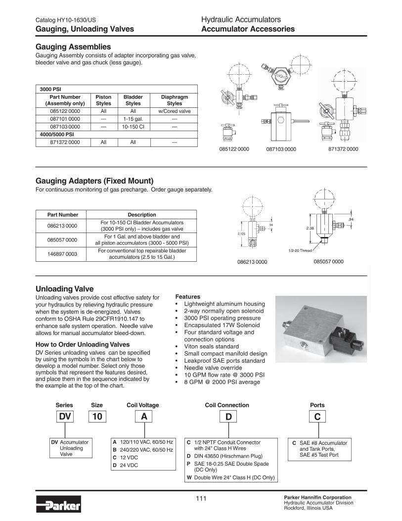
111 Parker Hannifin CorporationHydraulic Accumulator DivisionRockford, Illinois USA
Catalog HY10-1630/US Hydraulic AccumulatorsAccumulator Accessories
Access
ori
es
Gauging AssembliesGauging Assembly consists of adapter incorporating gas valve,bleeder valve and gas chuck (less gauge).
3000 PSIPart Number Piston Bladder Diaphragm
(Assembly only) Styles Styles Styles085122 0000 All All w/Cored valve
087101 0000 — 1-15 gal. —
087103 0000 — 10-150 CI —
4000/5000 PSI871372 0000 All All —
2.125
.94
Gauging Adapters (Fixed Mount)For continuous monitoring of gas precharge. Order gauge separately.
086213 0000 085057 0000
2.38
.94
1/2-20 Thread
Gauging, Unloading Valves
085122 0000 871372 0000087103 0000
Part Number Description
086213 0000For 10-150 CI Bladder Accumulators(3000 PSI only) – includes gas valve
085057 0000For 1 Gal. and above bladder and
all piston accumulators (3000 - 5000 PSI)
146897 0003For conventional top repairable bladder
accumulators (2.5 to 15 Gal.)
Features• Lightweight aluminum housing• 2-way normally open solenoid• 3000 PSI operating pressure• Encapsulated 17W Solenoid• Four standard voltage and
connection options• Viton seals standard• Small compact manifold design• Leakproof SAE ports standard• Needle valve override• 10 GPM flow rate @ 3000 PSI• 8 GPM @ 2000 PSI average
Unloading ValveUnloading valves provide cost effective safety foryour hydraulics by relieving hydraulic pressurewhen the system is de-energized. Valvesconform to OSHA Rule 29CFR1910.147 toenhance safe system operation. Needle valveallows for manual accumulator bleed-down.
How to Order Unloading ValvesDV Series unloading valves can be specifiedby using the symbols in the chart below todevelop a model number. Select only thosesymbols that represent the features desired,and place them in the sequence indicated bythe example at the top of the chart.
Series Size Coil Voltage Coil Connection Ports
DV 10 A D C
A 120/110 VAC, 60/50 Hz
B 240/220 VAC, 60/50 Hz
C 12 VDC
D 24 VDC
DV AccumulatorUnloadingValve
C SAE #8 Accumulatorand Tank Ports,SAE #5 Test Port
C 1/2 NPTF Conduit Connectorwith 24" Class H Wires
D DIN 43650 (Hirschmann Plug)
P SAE 18-0.25 SAE Double Spade(DC Only)
W Double Wire 24" Class H (DC Only)

Hydraulic AccumulatorsAccumulator Accessories
112 Parker Hannifin CorporationHydraulic Accumulator DivisionRockford, Illinois USA
Catalog HY10-1630/US
Description Part No
Pull Rod (1 Qt.-21/ 2 Gal.) 085109 0250
Pull Rod (5 Gal.) 085109 0500
Pull Rod (10-11 Gal.) 085109 1000
Pull Rod (15 Gal.) 085109 1500
Core Repair Tool 582441 0000
Core Installation Tool 300987
Spanner Wrench 085110 0000
Accumulator Repair Tools
Repair Tools and Adapters
Port Adapters
SAE to SAE Port Adapters
Part Number Description
5626840000 #24 SAE to #20 SAE
5626850000 #24 SAE to #16 SAE
5626860000 #24 SAE to #12 SAE
5626870000 #20 SAE to #16 SAE
5626880000 #20 SAE to #12 SAE
5626890000 #20 SAE to #10 SAE
0864730000 #16 SAE to #12 SAE
5626900000 #12 SAE to #10 SAE
5626910000 #12 SAE to #8 SAE
5720860000 #32 SAE to #24 SA
5720870000 #32 SAE to #20 SAE
5720880000 #32 SAE to #16 SAE
SAE to NPT Port Adapters
Part Number Description
5626810000 #24 SAE to 1-1/2" NPT
5626820000 #20 SAE to 1-1/4" NPT
5626830000 #12 SAE to 3/4" NPT
5720890000 #32 SAE to 2" NPT
6560070001 #12 SAE to 1/2" NPT
6560070002 #20 SAE to 1" NPT
1. Bladder Pull Rods — (Bladder Type Accumulator) Pullrods are available in different lengths for different sizeaccumulators. The pull rods attach to the gas valve of thebladder for ease of assembly into shell during reassembly.
2. Core Tool — The core tool is used to remove and reinstallthe valve core. It is also used to ream valve seat and repairthreads.
3. Spanner Wrench — Fits all standard size bladderaccumulators. Used to remove hydraulic poppet assemblyfrom accumulator shell.

113 Parker Hannifin CorporationHydraulic Accumulator DivisionRockford, Illinois USA
Catalog HY10-1630/US Hydraulic AccumulatorsAccumulator Accessories
F
BA
G
C
D
E
H
Piston Bladder “U” Bolt A B C D E Thd. Wt.Bore Size Part No. Lbs.A2 — 0854370000 1/4 2-7/16 2-11/16 2-11/16 1-3/4 1/4-20 0.2
A3 1 Pint 0862090000 1/2 3-11/16 4-1/16 3-5/8 2 3/8-16 0.9
— 1 Qt. 0854380000 1/2 4-5/8 5-1/8 4-1/2 3 1/2-13 1.2
A4 — 0864960000 1/2 5 5-1/2 4-1/2 3 1/2-13 1.3
— 1 Gal. 0854390000 5/8 6-3/4 7-3/8 6-1/8 3-3/4 5/8-11 2.4
A6 — 0864970000 5/8 7-1/8 7-3/4 6-1/8 3-3/4 5/8-11 2.5
A7 — 0854400000 5/8 8-1/4 8-7/8 7 3-3/4 5/8-11 3.0
— 21/2 - 15 Gal. 0853360000 5/8 9 9-5/8 7-1/8 3-3/4 5/8-11 3.0
A9 — 0854410000 3/4 11-1/4 12 9-1/2 4-1/2 3/4-10 6.0
A12 — 0854420000 7/8 14-1/8 15 10-1/4 4-1/4 7/8-9 8.2
— *21/2 - 15 Gal. 0865020000 5/8 9-3/4 10-3/8 7-1/4 3-13/4 5/8-11 3.5
D
CB A
E
BC
AD
E
Base Bracket
Straps should be tight on the shell whenusing a bladder-type accumulator.
Rubber Ring
"U" Bolt
"U" BoltNuts included on all "U" Bolts.
AccumulatorModels (3000 PSI)
Part No. and Dimensions
“U” Bolts for Piston & Bladder-Type Accumulators
MountingPlate
Piston Accumulatoror Gas Bottle
1 inch max. 1 inch max.Welded Lug(2 places)
Mounting Holes(2 places)
"U" Bolt(2 places)
Bladder-Type AccumulatorBladder-type accumulators shouldbe mounted vertically with thehydraulic port down.
CAUTION: Bladder-typeaccumulators should never bemounted more than 25° anglefrom the vertical.
NOTE: “U” Bolts should never bemounted more than 1 inch fromend of accumulator (piston type).
Base Bracket Assembly for Bladder Accumulators
Part Number and Dimensions
Base BracketBladder Size Assembly A B C D E F G H Wt.
Part No. Lbs.
1 Gal. (3K) 1449100000 10.3 7.87 3.62 4.75 8.87 3.85 1.58 0.65 x .87 5
21/2-15 Gal. (3K) 1448720000 10.3 7.87 4.84 6.75 8.87 3.85 1.58 0.65 x .87 5
25-40 Gal. (3K) 1480020000 15.3 10.6 7.68 8.18 15.3 9.40 4.18 0.87 x 1.06 10
21/2-15 Gal. (5K) 1481410000 10.3 7.87 5.35 6.75 8.87 3.85 1.58 0.65 x .87 5
Mounting Accessories
AccumulatorModels

Hydraulic AccumulatorsAccumulator Accessories
114 Parker Hannifin CorporationHydraulic Accumulator DivisionRockford, Illinois USA
Catalog HY10-1630/US
DimensionsBladder Clamp A B C D E F G Wt.
Size Part No. Max. Max. Lbs.1 Qt., 150 C.I.
1466230000 4.5 3.9 5.5 6.3 2.6.35 x
1.2 1.8(Figure A) .51
1 Gal.1449080000 6.8 6.3 7.6 8.5 3.6
.35 x1.2 2.7(Figure A) .51
21/2-15 Gal. (3K)1449070000 9.0 8.5 10.0 11.7 4.8
.50 x1.2 4.2(Figure B) .75
21/2-15 Gal. (5K)1349200000 9.5 8.5 10.5 12.0 5.4
.50 x1.2 4.5(Figure B) .75
Clamp Brackets for Bladder-Type Accumulators
Figure B
Clamp Brackets
Clamp Brackets for Diaphragm and Small Piston and Bladder Accumulators
Figure A
G
D
A
BC
F
E
BC
E
F
A
D
Clamp Brackets for Series 4000 & Series 5000 Piston Accumulators
Piston Series 4000 Series 5000Bore Size Part Number Part Number
2” 8700110252 8700110252
3” 8700110358 8700110413
4” 8700110535 87001100535
6” — —
7” N/A 8701960890
9” N/A 8701961220
Width1.25"
.37 x .5 (2)
.13
Typ.
HC
Ref
.
.24
DRubberSleeve
AB
Part Dimensions Accumulator Style/Size
No. A B C D H Diaphragm Piston Bladderliters/cu in bore/series liters/cu in
8700110238 4.25 3.35 4.29 2.25 / 2.41 1.58 — 2" / 3K 0.16 / 10
8700110252 4.25 3.35 4.42 2.62 / 2.82 1.64 0.075 / 5 2" / 4-5K —
8700110291 4.25 3.35 4.84 2.81 / 3.01 1.86 0.16 / 10 — —
8700110358 5.00 3.94 5.62 3.50 / 3.62 2.28 0.35 / 20 3" / 3-4K 0.50 / 30
8700110413 5.25 4.33 6.06 4.04 / 4.22 2.45 0.50 / 30 3" / 5K —
8700110476 5.25 4.33 6.71 4.67 / 4.90 2.77 0.75 / 45 4" / 3K 1-3 / 60-150
8700110535 5.75 4.92 7.43 5.32 / 5.50 3.21 1.0 / 60 — —
8700110630 7.00 5.98 8.29 6.25 / 6.37 3.571.4 / 85 &
— —2.0 / 120
1449080000 7.60 6.30 8.50 6.80 3.60 2.8 / 170 — —

101 Parker Hannifin CorporationHydraulic Accumulator DivisionRockford, Illinois USA
Large Gas Bottles• Series GB
GB Series Large Gas Bottles Feature:• Capacities from 40 to 150 Gallons
• High Strength Alloy Steel with Forged Ends
• Large 16" Diameter Shells
• Variety of Port Options

Large Gas BottlesSeries GB
102 Parker Hannifin CorporationHydraulic Accumulator DivisionRockford, Illinois USA
Catalog HY10-1630/US
Introduction
Where space does not permit the installation of the requiredcapacity accumulator, a smaller accumulator may be used byconnecting it to a gas bottle(s) that can be located in a nearbyspot where space is available. In some cases, an accumulatorand gas bottle combination may be lower in cost, especially withlarge capacity applications.
Why Use GB Series Gas Bottles?• reduce initial hydraulic system
costs
• broad range of sizes andoperating pressures
• heavy duty forged construction
• minimize plumbing with fewerlarge bottles
• interface well with Parker’saccumulator products, especiallypiston accumulators
Parker GB SeriesGas Bottles…The Right Choice!Parker is the leading manufacturerof accumulators in North America.In addition to gas bottles, Parker’sbroad product line includes pistonaccumulators, bladder accumula-tors, and diaphragm accumulators.Parker’s broad gas bottle offeringincludes:
• Large GB Series gas bottles(shown here)
• Piston Type Bottles(see Piston Accumulators )
• Bladder Type Bottles(see Bladder Accumulators)
SpecificationsMaterials• Shell – high strength alloy steel, SA-372, exterior coated
with primer.• Ports – steel• Gas Valve Cartridge – stainless steel
Pressure Ratings – Parker’s GB Series offers 3200 psi and5500 PSI gas bottles rated at minimum 3 to 1 design factors.See Models, Capacities and Dimensions for specific pressureratings by size. Temperatures from -20°F to 200°F (-29°C to93°C).
Optional Gas Valve – GB Series gas bottles are supplied asstandard with high pressure cored gas valve cartridges (ISO-4570-8V1). Poppet type (military) gas valves (Mil. Spec. MS-28889-2) are available as an option.
Standard and Optional Ports – GB Series gas bottles areoffered with 2" SAE 4-bolt flange ports as standard. Metricflange, SAE straight thread, and special ports are available asoptions, see next page for details.
Certifications – GB Series gas bottles are supplied asstandard with ASME Section VIII Div. 1, Appendix 22 Certifica-tion. See page 3 for a complete certifications summary.

103 Parker Hannifin CorporationHydraulic Accumulator DivisionRockford, Illinois USA
Large Gas BottlesSeries GB
Catalog HY10-1630/US
Models, Capacities and Dimensions
Capacity A B C WeightGallons in. in. Port Size lbs.
Model (Liters) (mm) (mm) (kg)
GB16040A32PL1A140 16 69 2" Code 61 660
(151.2) (406) (1753) SAE Flange (300)
GB16050A32PL1A150 16 82 2" Code 61 785
(189.0) (406) (2083) SAE Flange (357)
GB16060A32PL1A160 16 96 2" Code 61 912
(226.8) (406) (2438) SAE Flange (415)
GB16070A32PL1A170 16 110 2" Code 61 1043
(264.6) (406) (2794) SAE Flange (474)
GB16080A32PL1A180 16 123 2" Code 61 1175
(302.4) (406) (3124) SAE Flange (534)
GB16090A32PL1A190 16 136 2" Code 61 1300
(340) (406) (3454) SAE Flange (591)
GB16100A32PL1A1100 16 150 2" Code 61 1436
(378) (406) (3810) SAE Flange (653)
GB16125A32PL1A1125 16 184 2" Code 61 1755
(473) (406) (4674) SAE Flange (798)
GB16150A32PL1A1150 16 218 2" Code 61 2075
(567) (406) (5537) SAE Flange (943)
3200 PSI (220 Bar)
Capacity A B C WeightGallons in. in. Port Size lbs.
Model (Liters) (mm) (mm) Thd. Size (kg)
GB16040A55PQ1A140 16 77 2" Code 62 1180
(151.2) (406) (1956) SAE Flange (536)
GB16050A55PQ1A150 16 92 2" Code 62 1420
(189.0) (406) (2337) SAE Flange (645)
GB16060A55PQ1A160 16 108 2" Code 62 1650
(226.8) (406) (2743) SAE Flange (750)
GB16070A55PQ1A170 16 123 2" Code 62 1898
(264.6) (406) (3124) SAE Flange (863)
GB16080A55PQ1A180 16 138 2" Code 62 2128
(302.4) (406) (3505) SAE Flange (967)
GB16090A55PQ1A190 16 153 2" Code 62 2358
(340) (406) (3886) SAE Flange (1072)
GB16100A55PQ1A1100 16 168 2" Code 62 2606
(378) (406) (4267) SAE Flange (1185)
GB16125A55PQ1A1125 16 207 2" Code 62 3190
(473) (406) (5258) SAE Flange (1450)
GB16150A55PQ1A1150 16 244 2" Code 62 3795
(567) (406) (6198) SAE Flange (1725)
5500 PSI (380 Bar)
Port Size C D E F
2" SAE Code 61 2.0 1.688 3.062 1/2-13 UNC - 2B
2" SAE Code 62 2.0 1.750 3.812 3/4-10 UNC - 2B
B
A
C
D
E
F
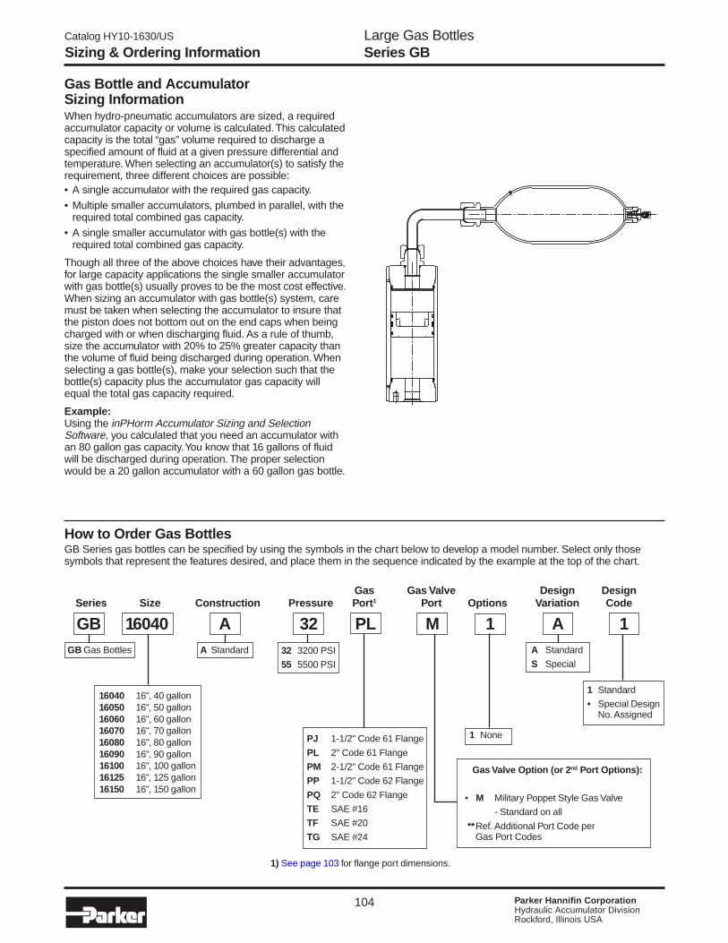
Large Gas BottlesSeries GB
104 Parker Hannifin CorporationHydraulic Accumulator DivisionRockford, Illinois USA
Catalog HY10-1630/US
Sizing & Ordering Information
Gas Bottle and AccumulatorSizing InformationWhen hydro-pneumatic accumulators are sized, a requiredaccumulator capacity or volume is calculated. This calculatedcapacity is the total “gas” volume required to discharge aspecified amount of fluid at a given pressure differential andtemperature. When selecting an accumulator(s) to satisfy therequirement, three different choices are possible:• A single accumulator with the required gas capacity.
• Multiple smaller accumulators, plumbed in parallel, with therequired total combined gas capacity.
• A single smaller accumulator with gas bottle(s) with therequired total combined gas capacity.
Though all three of the above choices have their advantages,for large capacity applications the single smaller accumulatorwith gas bottle(s) usually proves to be the most cost effective.When sizing an accumulator with gas bottle(s) system, caremust be taken when selecting the accumulator to insure thatthe piston does not bottom out on the end caps when beingcharged with or when discharging fluid. As a rule of thumb,size the accumulator with 20% to 25% greater capacity thanthe volume of fluid being discharged during operation. Whenselecting a gas bottle(s), make your selection such that thebottle(s) capacity plus the accumulator gas capacity willequal the total gas capacity required.
Example:Using the inPHorm Accumulator Sizing and SelectionSoftware, you calculated that you need an accumulator withan 80 gallon gas capacity. You know that 16 gallons of fluidwill be discharged during operation. The proper selectionwould be a 20 gallon accumulator with a 60 gallon gas bottle.
How to Order Gas BottlesGB Series gas bottles can be specified by using the symbols in the chart below to develop a model number. Select only thosesymbols that represent the features desired, and place them in the sequence indicated by the example at the top of the chart.
Gas Gas Valve Design DesignSeries Size Construction Pressure Port1 Port Options Variation Code
GB 16040 A 32 M 1 A 1A StandardGB Gas Bottles
16040 16", 40 gallon16050 16", 50 gallon16060 16", 60 gallon16070 16", 70 gallon16080 16", 80 gallon16090 16", 90 gallon16100 16", 100 gallon16125 16", 125 gallon16150 16", 150 gallon
PJ 1-1/2" Code 61 Flange
PL 2" Code 61 Flange
PM 2-1/2" Code 61 Flange
PP 1-1/2" Code 62 Flange
PQ 2" Code 62 Flange
TE SAE #16
TF SAE #20
TG SAE #24
Gas Valve Option (or 2nd Port Options):
• M Military Poppet Style Gas Valve
- Standard on all
**Ref. Additional Port Code perGas Port Codes
1 None
A Standard
S Special
1 Standard
• Special DesignNo. Assigned
32 3200 PSI
55 5500 PSI
PL
1) See page 103 for flange port dimensions.
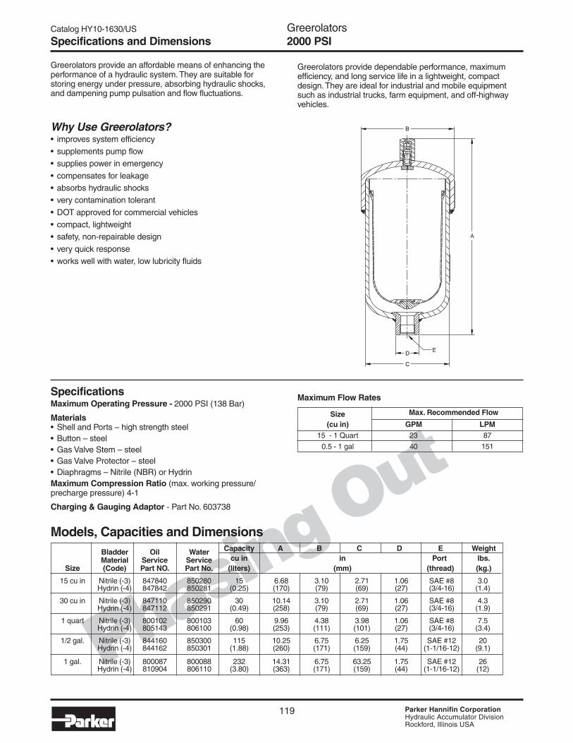
Catalog HY10-1630/US
119 Parker Hannifin CorporationHydraulic Accumulator DivisionRockford, Illinois USA
Phasing Out
Bladder Oil Water Capacity A B C D E Weight
Material Service Service cu in in Port lbs.Size (Code) Part NO. Part No. (liters) (mm) (thread) (kg.)
15 cu in Nitrile (-3) 847840 850280 15 6.68 3.10 2.71 1.06 SAE #8 3.0Hydrin (-4) 847842 850281 (0.25) (170) (79) (69) (27) (3/4-16) (1.4)
30 cu in Nitrile (-3) 847110 850290 30 10.14 3.10 2.71 1.06 SAE #8 4.3Hydrin (-4) 847112 850291 (0.49) (258) (79) (69) (27) (3/4-16) (1.9)
1 quart Nitrile (-3) 800102 800103 60 9.96 4.38 3.98 1.06 SAE #8 7.5Hydrin (-4) 805143 806100 (0.98) (253) (111) (101) (27) (3/4-16) (3.4)
1/2 gal. Nitrile (-3) 844160 850300 115 10.25 6.75 6.25 1.75 SAE #12 20Hydrin (-4) 844162 850301 (1.88) (260) (171) (159) (44) (1-1/16-12) (9.1)
1 gal. Nitrile (-3) 800087 800088 232 14.31 6.75 63.25 1.75 SAE #12 26Hydrin (-4) 810904 806110 (3.80) (363) (171) (159) (44) (1-1/16-12) (12)
Greerolators provide an affordable means of enhancing theperformance of a hydraulic system. They are suitable forstoring energy under pressure, absorbing hydraulic shocks,and dampening pump pulsation and flow fluctuations.
SpecificationsMaximum Operating Pressure - 2000 PSI (138 Bar)
Materials• Shell and Ports – high strength steel• Button – steel• Gas Valve Stem – steel• Gas Valve Protector – steel• Diaphragms – Nitrile (NBR) or HydrinMaximum Compression Ratio (max. working pressure/precharge pressure) 4-1
Charging & Gauging Adaptor - Part No. 603738
Why Use Greerolators?• improves system efficiency• supplements pump flow• supplies power in emergency
• compensates for leakage• absorbs hydraulic shocks• very contamination tolerant
• DOT approved for commercial vehicles• compact, lightweight• safety, non-repairable design
• very quick response• works well with water, low lubricity fluids
Greerolators provide dependable performance, maximumefficiency, and long service life in a lightweight, compactdesign. They are ideal for industrial and mobile equipmentsuch as industrial trucks, farm equipment, and off-highwayvehicles.
Size Max. Recommended Flow
(cu in) GPM LPM15 - 1 Quart 23 87
0.5 - 1 gal 40 151
Maximum Flow Rates
Models, Capacities and Dimensions
Specifications and Dimensions
B
C
D
A
E
Greerolators2000 PSI

141 Parker Hannifin CorporationHydraulic Accumulator DivisionRockford, Illinois USA
Catalog HY10-1630/US Hydraulic AccumulatorsMaintenance Instructions
Hydraulic Piston Accumulators
Piston Accumulators
InstallationAll accumulators shipped from the factory will bepre-charged to a nominal pressure in order to seatthe piston on the hydraulic cap. In this case theprecharge will not be listed on the label. However, insome cases they will be shipped with a nitrogencharge, the value of which will be marked on thelabel/nameplate.
Keep the hydraulic port covered to keep outforeignmaterial until ready to make the hydraulicconnections.
The accumulator can be mounted in anyorientation. However, it should be rigidly mountedusing any combination of the mounting holesprovided at the hydraulic cap or proper clamps. Thehydraulic circuit, which contains a connection to theaccumulator should be designed so that it automati-cally discharges all hydraulic fluid from the accumu-lator when the equipment is turned off.

142 Parker Hannifin CorporationHydraulic Accumulator DivisionRockford, Illinois USA
Catalog HY10-1630/US Hydraulic AccumulatorsMaintenance InstructionsPiston Accumulators
3000 PSI UNITS
Part #L07689000* Gas Valve withpoppet for ASME units 7, 9, 12bore and some 5000 psi units.
FIGURE 6Part #L07471000* Gas Valve withmedium pressure core for 3000 psiservice, and Part #L07688000* GasValve with high pressure core for5000 psi service.
FIGURE 5
5000 PSI UNITS
Pre-ChargingUse an inert gas such as nitrogen for pre-charging pistonaccumulators. Do not use oxygen or shop air.
If water pumped nitrogen is not available, oil-pumpednitrogen may be used. (C.G.A. standards: Nitrogen gasbottles for water pumped nitrogen has a right-hand valvethread which requires charging and gauging assembly†144595XX00 for units up to 3000 psi. Oil-pumped nitrogenrequires a left-handed valve thread (use †144596XX00). Forall 3000 psi rated accumulators, use assembly†144595XX00 (Figure 1). For accumulators rated over3000 psi and the precharge requirement is above 2300 psi,use †870816XX00 (See Figure 3).
If equipment other than the above listed is used, make sureit is compatible with the gas valve assembly. Nitrogensource and all components must be rated for a pressure atleast as high as the nitrogen source. It is strongly recom-mended that the nitrogen bottle used have the appropri-ate pressure high pressure regulator (not included).
Make sure nitrogen supply is shut off. Attach hose tonitrogen bottle. If accumulator has a gas valve as shown inFigure 5 follow steps A through L and skip steps F and J. Ifaccumulator has a gas valve as shown in Figure 6, followsteps A through L and skip steps E and I.
Accumulator having gas valve as per Figure 5.(A) Remove gas valve guard and gas valve cap.(B) Back gas chuck “T” handle all the way out (counter
clockwise) before attaching charging assembly toaccumulator gas valve.
(C) Close bleed valve.(D) Making sure not to loop or twist the hose, attach
swivel nut to gas valve and tighten (10-15 in. lb.)(11.5-17 cm kg).
(E) Turn gas chuck “T” handle until the gauge startsshowing the pressure in the accumulator. Do notturn the "T" handle all the way down, as it will damage the valve core.
(F) For gas valves as shown in Figure 6, hold gasvalve at point “C” with one (1) wrench while unscrewing hex nut at point “D” with a second wrench.This will open the poppet inside the gas valve. Note:Three (3) turns will fully open the valve.
(G) Crack open nitrogen bottle valve and slowly fillaccumulator. Shut off when gauge indicates desiredpre-charge.
(H) Let the pre-charge set for 10 to 15 minutes. This willallow the gas temperature to stabilize. If the desiredpre-charge is exceeded, close nitrogen bottle valve,then slowly open bleed valve (Figure 1). Do notreduce pre-charge by depressing valve core with aforeign object. High pressure may rupture rubbervalve seat.
(I) When finished pre-charging accumulator, turn “T”handle all the way out on gas chuck (Figure 1), thenopen bleed valve.
(J) For gas valves as shown in Figure 6, with awrench, tighten hex nut at point “D” to close internalpoppet (5-8 ft. lbs.) (5.7-9.2 cm kg).
(K) Hold gas valve to keep from turning, loosen swivelnut, remove assembly. Check for precharge leakusing a common leak reactant.
(L) Replace gas valve cap (10-15 in. lbs.) (11.5-17 cmkg) and valve guard. (Gas valve cap serves as asecondary seal.)
† "XX" Denotes to gauge pressure.
Gauging Assembly for Cored Accumulators
Gauging device consisting of adapter incorporating gasvalve, bleeder valve and gas chuck (less gauge).
Part Number
085122XX00
PART #870816XX00FIGURE 3 FIGURE 4
PART #871372XX00
Charging and Gauging Assembly for 5000 PSI
Charging and Gauging Assembly consists of 10' charginghose with standard right-hand thread nitrogen fittings(1.035-14 NGO female)adapter incorporating gas valve,bleeder valve and gas chuck (less gauge).
Part Number
870816XX00
Gauging Assembly for 5000 PSI
Gauging device consisting of adapter incorporating gasvalve, bleeder valve and gas chuck (less gauge).
Part Number
871372XX00
Charging and Gauging Assemblyfor Cored Accumulators
Charging and Gauging Assembly consists of 10' charginghose with standard right-hand thread nitrogen fittingsadapter incorporating gas valve, bleeder valve and gaschuck (less gauge). For left-hand thread nitrogen bottlefitting, specify part number 144596XX00.
Part Number
144595 XX00(Std)(Right-Hand)
FIGURE 2FIGURE 1PART #144595XX00 PART #085122XX00
ACCUMULATOR
POINT “D”
POINT “C”VALVECORE

143 Parker Hannifin CorporationHydraulic Accumulator DivisionRockford, Illinois USA
Catalog HY10-1630/US Hydraulic AccumulatorsMaintenance InstructionsPiston Accumulators
MaintenanceRepair Kits (see Parts List) are available for allaccumulator models. When ordering repair kits, statecomplete model number from nameplate. Also specify fluidand temperature at which used.
Occasional replacement of V-o-ring seal on the piston isgenerally the only maintenance required. Replacement ofother seals on end caps and gas valve is recommended(see Kit Numbers).
Periodic checking of pre-charge pressure will detectwhether V-o-ring wear is sufficient to begin reducing sealingperformance. If pre-charge is low, also check for gas valveand/or end seal leakage. Allowing for temperature differ-ence, if any, from time of its pressure checking, pre-chargepressure will rise if oil gathers in the gas side and will fall ifgas leaks into the oil side or out past gas end seals. It issuggested that a check be made a week after installation,and thereafter once a month.
Pre-charge Checking ProcedureUsing appropriate valve in the hydraulic system,discharge all oil from accumulator and allow piston tobottom against hydraulic end cap.
For accumulators rated for 3000 psi or less, with cored gasvalve, use gauging assembly as shown in Figure 2 (Part#085122XX00). For accumulators rated over 3000 psi up to5000 psi, use assembly as shown in Figure 4 (Part#871247XX00).
Accumulators having gas valve as perFigure 5. (1) Remove gas valve guard and gas valve cap. (2) Back gas chuck “T” handle all the way out (counter
clockwise) before attaching charging assembly toaccumulator gas valve.
(3) Close bleed valve. (4) Attach swivel nut to gas valve and tighten(10-15 in. lb.)
(11.5-17 cm kg). (5) Turn gas chuck “T” handle until the gauge starts
showing the pressure in the accumulator. Do not turnthe "T" handle all the way down, as it will damage thevalve core.
(6) To remove gauging assembly turn “T” handle all theway out on gas chuck (Figure 1), then open bleedvalve to relieve residual gas charge in the gaugingassembly.
(7) Hold gas valve from turning, loosen swivel nut, removeassembly.
(8) Replace gas valve cap (10-15 in. lbs.) (11.5-17 cm kg)and valve guard.
Accumulators having gas valve as perFigure 6. (9) Remove gas valve guard and gas valve cap.
(10) Close bleed valve.(11) Attach swivel nut to gas valve and tighten
(10-15 in. lb.) (11.5-17 cm kg).
(12) Hold gas valve at point “C” with one (1) wrench whileunscrewing hex nut at point “D” with a second wrench.This will open the poppet inside the gas valve. Turn 2-3 times and read pre-charge. Note: Three (3) turnswill fully open the valve.
(13) With a wrench, tighten hex nut at point “D” to closeinternal poppet (5-8 ft. lbs.) (5.7-9.2 cm kg) then openbleed valve to relieve residual gas charge in thegauging assembly.
(14) Hold gas valve at point “C” with wrench and removeswivel nut assembly.
(15) Replace gas valve cap and tighten (10-15 in. lb.)(11.5-17 cm kg), and install gas valve guard.
Remove from Hydraulic SystemShut equipment down and make certain that hydraulicpressure at the accumulator is at zero. At this point thepiston will be bottomed at the hydraulic end.
For accumulators having gas valve as shown in Figure5, attach gauging assembly as shown in Figure 2 followingSteps 1 through 5. Then, open bleed valve until all gas pre-charge is relieved from accumulator. Then remove gaugingassembly and gas valve.
For accumulators having gas valve as shown in Figure6, remove gas valve guard and gas valve cap. Then holdvalve at point “C” with one (1) wrench while unscrewing hexnut at point “D” with a second wrench. Wait until all gas pre-charge is relieved from the accumulator and then removegas valve.
Remove accumulator from hydraulic system. Threadedholes in hydraulic cap may be used as a means of attach-ment for lifting, or use a sling around the body.
Disassembly of AccumulatorOnce the gas valve is removed - lay the accumulatorhorizontal and hold down with a strap wrench or in a vise.Some accumulators may have both end caps threaded intothe body and some units may only have the gas capthreaded into the body. IN BOTH CASES ALWAYS RE-MOVE THE GAS CAP FIRST (end cap which contained gasvalve). To remove cap or caps, install three (3) pins into theholes in the cap, then, using a long bar working against thepins, unthread the cap from the body. Remove o-rings andback-up rings from end cap.
Remove piston by pushing from hydraulic end with a bar.NEVER TRY TO REMOVE PISTON BY APPLYING COM-PRESSED AIR AT OPPOSITE END. To remove V-o-ringfrom piston, lift seal with O-ring pick or similar tool, movingthe tool around the piston several times while using theother hand to work ring off the piston.
CleaningThoroughly clean metal parts in solvent and dry withcompressed air. Clean bore of body with a clean, lint-freecloth soaked in clean solvent. Bore must be clean of anyvisible particles or particles detectable to touch.
InspectionInspect piston for cracks, burrs around o-ring grooves, ordamage. Examine body bore, using a light, for scratches orscoring. Inspect end caps for damaged threads or burrs ono-ring grooves.
Repair and ReplacementMinor nicks, scratches or light scoring of the body bore canbe removed by using crocus cloth. Dress bore until allapparent imperfections have been removed. Replace PTFEwear rings, V-o-rings, o-rings and their respective back-upwashers if the original assembly contained them.

144 Parker Hannifin CorporationHydraulic Accumulator DivisionRockford, Illinois USA
Catalog HY10-1630/US Hydraulic AccumulatorsMaintenance Instructions
ReassemblyCoat all internal parts with clean hydraulic fluid beforereassembly.
It is highly recommended to use a piston starting sleeve forreassembly of piston accumulators. Call the factory for priceand delivery. Starting sleeve dimensions are shown below.Insert the piston in the starting sleeve with the dished sideof the piston toward the gas end. Insert the starting sleevein the accumulator tube until it rests square on the tube.
Use hammer and a brass rod to tap piston into place until allof piston is 2 inches below beginning of honed bore.
Install new back-up ring first, then a new o-ring on threadedend cap or caps and install into body bore. Care should beexercised not to drag o-ring over threads. End cap will stopagainst chamfer leading into honed bore (all caps must betightened to proper torque as per following chart). Capshould be above the end of accumulator body within 1/32" to3/32".
Install gas valve after replacing the o-ring.
Remount accumulator and connect to hydraulic system. Pre-charge accumulator to desired precharge pressure (wherespace is a problem it may be necessary to pre-chargeaccumulator before connecting it to the hydraulic system).
ASSEMBLY TORQUEBORE SIZE Ft. Lb.
2 50+ 5.03 90+ 7.04 160+ 10.06 220+ 15.07 390+ 25.08 390+ 25.09 390+ 25.012 390+ 25.0
BOREPART NUMBER A B C D E F G H J SERVICE SIZE
PSD0000002 2.375 2.375 2.110 2.025 .100 .030 1.375 1.032 7 3K,4K,5K 2PSD0000003 3.560 2.750 3.110 3.000 .131 .030 1.750 1.312 7 3K,4K,5K 3PSD0000004 4.750 3.250 4.110 4.030 .089 .030 2.250 1.375 7 3K 4PSD0000005 6.000 3.500 5.112 5.002 .124 .030 2.500 1.620 7 3K 5PSD0000006 6.875 4.375 5.864 5.782 .104 .030 3.375 1.562 7 3K 6PSD0000007 8.250 5.000 7.150 7.001 .173 .030 4.000 2.312 7 3K 7PSD0000009 11.000 5.500 9.150 9.001 .174 .030 4.000 2.562 7 3K 9PSD0000012 14.375 6.375 12.105 11.876 .268 .030 4.875 3.634 7 3K 12
PARTS LIST
Piston Accumulators

145 Parker Hannifin CorporationHydraulic Accumulator DivisionRockford, Illinois USA
Catalog HY10-1630/US Hydraulic AccumulatorsMaintenance Instructions
Ma
int.
Piston Accumulators
Parts List — Hydraulic Accumulators
Seal Kit Numbers (Includes items 5, 5A, 6, 7, 7A, 8A)
*C.F. = Consult Factory
Material 2" 3" 4" 6" 7" 9" 12"Buna-N (Std.) RK0200K000 RK0300K000 RK0400K000 RK0600K000 RK0700K000 RK0900K000 RK1200K000Fluorocarbon RK0200E000 RK0300E000 RK0400E000 RK0600E000 RK0700E000 RK0900E000 RK1200E000EPR RK0200D000 RK0300D000 RK0400D000 RK0600D000 RK0700D000 RK0900D000 C.F.*Hydrogenated Nitrile RK0200H000 RK0300H000 RK0400H000 RK0600H000 RK0700H000 C.F.* C.F.*Low Temp Nitrile RK0200Q000 RK0300Q000 RK0400Q000 RK0600Q000 RK0700Q000 RK0900Q000 C.F.*
Bore Size
Item Part Description
1* Body 2* Hydraulic Cap3 Gas Cap4 Piston5 V-O-Ring
5A V-O-Ring Back-Up Washers6 PTFE Ring (Piston)7 O-Ring
7A O-Ring Back-Up Washer8 Gas Valve
8A Gas Valve O-Ring9 Gas Valve Guard
9A Screw
* Some units may have these twocomponents welded together.A.S.M.E. Units, 7", 9" and 12"bore sizes, and some units ratedabove 3000 PSI will have valve perFigure 6 (Part No. L07689000*). Otherunits will have gas valve per Figure 5(Part No. L07471000*) which will containgas valve core Part No. 5822220000.Use tool (Part No. 5824410000) toremove and replace new core.

146 Parker Hannifin CorporationHydraulic Accumulator DivisionRockford, Illinois USA
Catalog HY10-1630/US Hydraulic AccumulatorsMaintenance InstructionsPiston Accumulators

147 Parker Hannifin CorporationHydraulic Accumulator DivisionRockford, Illinois USA
Catalog HY10-1630/US Hydraulic AccumulatorsMaintenance Instructions
Hydraulic PistonAccumulatorsCE Marking
What is the Pressure Equipment Directive?
The Pressure Equipment Directive (PED) is one of the series of technical harmonisation directives coveringsubjects such as machinery, simple pressure vessels, gas applicances etc., which were identified by the Euro-pean Community's program for the elimination of technical barriers to trade. The purpose of the PED is toharmonise national laws of member states regarding the design, manufacture, testing and conformity assess-ment of pressure equipment and assemblies of pressure equipement.
The program aims to ensure the free placing on the market and putting into service of relevant equipment withinthe European Union and the European Economic Area. The Pressure Equipment Directive provides for aflexible regulatory environment which does not impose any technical solution.
The Directive requires that all pressure equipment and assemblies within its scope must be safe when placedon the market and put into service. Safe pressure equipment and assemblies are defined as those which, whenproperly installed and maintained and used for their intended purpose, will not endanger the health and safetyof persons and, where appropriate, domestic animals and property.
Units 1 liter and greater in gas capacity can be identified by a CE Marking place on the product label attachedto the accumulator. Units under 1 liter in gas capacity are designed and manufactured in accordance withSound Engineering Practice (S.E.P.) in order to ensure safe use. Such units do not bear the CE Marking.
Piston Accumulators – CE Marking

148 Parker Hannifin CorporationHydraulic Accumulator DivisionRockford, Illinois USA
Catalog HY10-1630/US Hydraulic AccumulatorsMaintenance InstructionsPiston Accumulators – CE Marking
Basic safety equipment for a single accumulator with permanently connected safety valve and gauge, gaugecontrol port, manually operated shut-off device, pressure release device and return line to the reservoir. Safetycomponents may be connected by lines and/or installed in a safety block. The accumulator must always beprotected with sufficient discharge capacity. If a check valve prevents flow back to the pressure source (pump), ashut-off device is not required for safety reasons but may be appropriate for service and maintenance.
Configuration with additional pressure release device which opens automatically in the case of circuit break down.
Example 1
Example 2
InstallationMost accumulators shipped from the factory will not be pre-charged. However, in some cases they will beshipped with some amount of nitrogen charge, the value of which will be stamped on the nameplate.
Keep the hydraulic port covered to keep out foreign material until ready to make the hydraulic connections.
The accumulator can be mounted in any orientation; vertically mounted with hydraulic port down is perferred.However, it should be rigidly mounted using any combination of the mounting holes provided at the hydraulic capor proper clamps. The hydraulic circuit, which contains a connection to the accumulator should be designed sothat it automatically discharges all hydraulic fluid from the accumulator when the equipment is turned off.

149 Parker Hannifin CorporationHydraulic Accumulator DivisionRockford, Illinois USA
Catalog HY10-1630/US Hydraulic AccumulatorsMaintenance InstructionsPiston Accumulators – CE Marking
Configuration with a 3/2-way-directional-control which simultaneously serves to isolate the accumulator from thepresure line and release pressure to the return line. The safety valve is permanently communicating with thepressure line, therefore also protecting the circuit. The accumulator is either protected by the safety valve orconnected to the return line.
The above configuration shows a group of several accumulators connected with a single pressure line which ispermanently connected with a gauge and a safety valve. Each individual accumulator may be isolated from thepressure line by a shut-off device and relased by a pressure device to a return line for maintenance purposes. Anexternal control gauge connected to a quick coupling allows observation of the pressure at the fluid port of eachindividual accumulator.
Example 3
Example 4

150 Parker Hannifin CorporationHydraulic Accumulator DivisionRockford, Illinois USA
Catalog HY10-1630/US Hydraulic AccumulatorsMaintenance InstructionsPiston Accumulators – CE Marking
Example 6
Configuration for a transfer type accumulator with additional gas bottles. Safety equipment for filling proceduresis not shown.
Example 5
Configuration similar to example 1 but with serveral accumulators each equipped with a safety block. Each safetyblock includes a safety valve, shut-off device, pressure release device and ports for the pressure line, the returnline, gauge, control gauge and the accumulator itself. This configuration meets all safety requirements even forseveral pressure sources.

151 Parker Hannifin CorporationHydraulic Accumulator DivisionRockford, Illinois USA
Catalog HY10-1630/US Hydraulic AccumulatorsMaintenance InstructionsPiston Accumulators – CE Marking
“U” Bolts for Piston-Type Accumulators
Notes: 1) Accumulators should be mounted within 20° from vertical for optimal performance. 2) "U" Bolts should never be mounted more than 1 inch from end of accumulator.
"U" Bolt Wt.Bore 3,000 PSI Part Number A B C D E Thrd. (lbs.)
A2 0854370000 1/4 2-7/16 2-11/16 2-11/16 1-3/4 1/4-20 0.2A3 0862090000 1/2 3-11/16 4-1/16 3-5/8 2 3/8-16 0.9A4 0864960000 1/2 5 5-1/2 4-1/2 3 1/2-13 1.3A6 0864970000 5/8 7-1/8 7-3/4 6-1/8 3-3/4 5/8-11 2.5A7 0854400000 5/8 8-1/4 8-7/8 7 3-3/4 5/8-11 3.0A9 0854410000 3/4 11-1/4 12 9-1/2 4-1/2 3/4-10 6.0A12 0854420000 7/8 14-1/8 15 10-1/4 4-1/4 7/8-9 8.2
D
CB A
E
"U" BoltNuts included on all "U" Bolts.
MountingPlate
Piston Accumulatoror Gas Bottle
1 inch max. 1 inch max.Welded Lug(2 places)
Mounting Holes(2 places)
"U" Bolt(2 places)

152 Parker Hannifin CorporationHydraulic Accumulator DivisionRockford, Illinois USA
Catalog HY10-1630/US Hydraulic AccumulatorsMaintenance Instructions
Water Service Option (W)Piston accumulators are available for use with water as the fluid media. Modifications include electroless nickel plating all surfacesand metal parts. Consult factory for details.
*Note: Consult local distributor or factory for fluid compatibility information. Temperature ranges may vary depending upon fluid used in hydraulic system.
Accumulator StorageIn order to prepare a piston accumulator for proper storage for future use, the piston must be moved off the hydraulic cap by asmuch as 2 inches. Proceed by pouring 10 to 150 cubic inches (depending on the size of accumulator) of the system fluidthrough the hydraulic port in the accumulator end and plug the port using a stainless steel fitting, then pre-charge the unit withnitrogen to 100±10 psig to allow equal pressure on both sides of the seal.
The pre-charge should be bled off and the system fluid in the accumulator must be drained prior to installation of the pistonaccumulator on the system .
It is also recommended that the units be stored in a vertical position to prevent the seals form developing a set (flat spot) onthe side that the piston weight is exerted.
The piston accumulator should be stored in a cool, dry place away from sun, ultraviolet and fluorescent lights as well aselectrical equipment. Direct sunlight or fluorescent light can cause the seals to weather check and dry rot, which appear onthe seal and o-ring surface as cracks. The ideal temperature for storage is 70°F.
Accumulator Sizing and Selection SoftwareParker offers leading edge application assistance, in the form of the InPHorm Accumulator Sizing and Selection Software or visitwww.parker.com/accumulator for more information. For further engineering assistance, contact Parker's Accumulator TechnicalSupport Group at (815) 636-4100.
Corrosive Fluids and EnviromentmentsStandard piston accumulators are not designed for corrosive fluids and enviroments. Consult factory for special options for thesetypes of fluids and enviromentments.
** The temperature listed indicates the operating temperature range of the seals, not the accumulator.
Accumulator SealsPiston accumulators are available for use with many operating medias. Fluid should be a non-dangerous liquid as well asprecharged with an inert gas such as nitrogen. Available seal compounds are shown in the table below:
**Recommended MaximumSeal Operating Temperature with General ApplicationCode Polymer Temperature Range Reduced Life and Compatibility*
K Buna- -20ºF to 165ºF 200ºF Parker's Standard Compound - CompatibleNitrile 29ºC to 74ºC 93ºC with most mineral oil-based fluids
E Fluorocarbon -10ºF to 250ºF 400ºF Compatible with most mineral oil-based fluids atElastomer -23ºC to 121ºC 204ºC higher temperatures and some exotic fluids
D Ethylene -40ºF to 250ºF 300ºF Compatible with most phosphate ester fluidsPopylene -40ºC to 121ºC 149ºC and some synthetic fluids
H Hydrogenated -45ºF to 325ºF 350ºF Compatible with most oil-based and biodegradable fluidsNitrile -43ºC to 162ºC 177ºC maintains sealing effectiveness at low temperatures
Q Low Temp. -45ºF to 160ºF 200ºF Compatible with most mineral oil-based fluids andNitrile -43ºC to 74ºC 93ºC maintains sealing effectiveness at low temperatures
Piston Accumulators – CE Marking

153 Parker Hannifin CorporationHydraulic Accumulator DivisionRockford, Illinois USA
Catalog HY10-1630/US Hydraulic AccumulatorsMaintenance Instructions
Ma
int.
Piston Accumulators – CE Marking
3000 PSI UNITS
Part #L07689000* Gas Valve withpoppet for ASME units 7, 9, 12 boreand some 5000 psi units
FIGURE 6
Part #L07471000* Gas Valve withmedium pressure core for 3000 psiservice, and Part #L07688000* GasValve with high pressure core for5000 psi service.
FIGURE 5
5000 PSI UNITS
Pre-ChargingUse an inert gas such as nitrogen for pre-charging pistonaccumulators. Do not use oxygen or shop air.
If water pumped nitrogen is not available, oil-pumpednitrogen may be used. (C.G.A. standards: Nitrogen gasbottles for water pumped nitrogen has a right-hand valvethread which requires charging and gauging assembly†144595XX00 for units up to 3000 psi. Oil-pumped nitrogenrequires a left-handed valve thread (use †144596XX00). Forall 3000 psi rated accumulators, use assembly†144595XX00 (Figure 1). For accumulators rated over3000 psi and the precharge requirement is above 2300 psi,use †870816XX00 (See Figure 3).
If equipment other than the above listed is used, make sureit is compatible with the gas valve assembly. Nitrogensource and all components must be rated for a pressure atleast as high as the nitrogen source. It is strongly recom-mended that the nitrogen bottle used have the appropri-ate pressure high pressure regulator (not included).
Make sure nitrogen supply is shut off. Attach hose tonitrogen bottle. If accumulator has a gas valve as shown inFigure 5 follow steps A through L and skip steps F and J. Ifaccumulator has a gas valve as shown in Figure 6, followsteps A through L and skip steps E and I.
Accumulator having gas valve as per Figure 5.(A) Remove gas valve guard and gas valve cap.(B) Back gas chuck “T” handle all the way out (counter
clockwise) before attaching charging assembly toaccumulator gas valve.
(C) Close bleed valve.(D) Making sure not to loop or twist the hose, attach
swivel nut to gas valve and tighten (10-15 in. lb.)(11.5-17 cm kg).
(E) Turn gas chuck “T” handle until the gauge startsshowing the pressure in the accumulator. Do notturn the "T" handle all the way down, as it willdamage the valve core.
(F) For gas valves as shown in Figure 6, hold gasvalve at point “C” with one (1) wrench while unscrewing hex nut at point “D” with a second wrench.This will open the poppet inside the gas valve. Note:Three (3) turns will fully open the valve.
(G) Crack open nitrogen bottle valve and slowly fillaccumulator. Shut off when gauge indicates desiredpre-charge.
(H) Let the pre-charge set for 10 to 15 minutes. This willallow the gas temperature to stabilize. If the desiredpre-charge is exceeded, close nitrogen bottle valve,then slowly open bleed valve (Figure 1). Do notreduce pre-charge by depressing valve core with aforeign object. High pressure may rupture rubbervalve seat.
(I) When finished pre-charging accumulator, turn “T”handle all the way out on gas chuck (Figure 1), thenopen bleed valve.
(J) For gas valves as shown in Figure 6, with awrench, tighten hex nut at point “D” to close internalpoppet (5-8 ft. lbs.) (5.7-9.2 cm kg).
(K) Hold gas valve to keep from turning, loosen swivelnut, remove assembly. Check for precharge leakusing a common leak reactant.
(L) Replace gas valve cap (10-15 in. lbs.) (11.5-17 cmkg) and valve guard. (Gas valve cap serves as asecondary seal.)
† "XX" Denotes to gauge pressure.
PART #870816XX00FIGURE 3 FIGURE 4
PART #871372XX00
Charging and Gauging Assembly for 5000 PSI
Charging and Gauging Assembly consists of 10' charginghose with standard right-hand thread nitrogen fittings(1.035-14 NGO female)adapter incorporating gas valve,bleeder valve and gas chuck (less gauge).
Part Number
870816XX00
Gauging Assembly for 5000 PSI
Gauging device consisting of adapter incorporating gasvalve, bleeder valve and gas chuck (less gauge).
Part Number
871372XX00
Charging and Gauging Assemblyfor Cored Accumulators
Charging and Gauging Assembly consists of 10' charginghose with standard right-hand thread nitrogen fittingsadapter incorporating gas valve, bleeder valve and gaschuck (less gauge). For left-hand thread nitrogen bottlefitting, specify part number144596XX00.
Part Number
144595XX00(Std)(Right-Hand)
FIGURE 2
FIGURE 1PART #144595XX00
PART #085122XX00
Gauging Assembly for Cored AccumulatorsGauging device consisting of adapter incorporatinggas valve, bleeder valve and gas chuck (less gauge).
Part Number085122XX00
ACCUMULATOR
POINT “D”
POINT “C”VALVECORE

154 Parker Hannifin CorporationHydraulic Accumulator DivisionRockford, Illinois USA
Catalog HY10-1630/US Hydraulic AccumulatorsMaintenance InstructionsPiston Accumulators – CE Marking
MaintenanceRepair Kits (see Parts List) are available for all accumulatormodels. When ordering repair kits, state complete modelnumber from nameplate. Also specify fluid and temperature atwhich used.
Occasional replacement of V-o-ring seal on the piston isgenerally the only maintenance required. Replacement of otherseals on end caps and gas valve is recommended (see KitNumbers).
Periodic checking of pre-charge pressure will detect whether V-o-ring wear is sufficient to begin reducing sealing performance.If pre-charge is low, also check for gas valve and/or end sealleakage. Allowing for temperature difference, if any, from time ofits pressure checking, pre-charge pressure will rise if oilgathers in the gas side and will fall if gas leaks into the oil sideor out past gas end seals. It is suggested that a check be madea week after installation, and thereafter once a month.
Pre-charge Checking ProcedureUsing appropriate valve in the hydraulic system, discharge alloil from accumulator and allow piston to bottom againsthydraulic end cap.
For accumulators rated for 3000 psi or less, use gaugingassembly as shown in Figure 2 (Part #085122XX00). Foraccumulators rated over 3000 psi up to 5000 psi, use assemblyas shown in Figure 4 (Part #87127XX00).
Accumulators having gas valve as perFigure 5. (1) Remove gas valve guard and gas valve cap.
(2) Back gas chuck “T” handle all the way out (counterclockwise) before attaching charging assembly toaccumulator gas valve.
(3) Close bleed valve.
(4) Attach swivel nut to gas valve and tighten(10-15 in. lb.) (11.5-17 cm kg).
(5) Turn gas chuck “T” handle all the way down. Thiswill depress core in gas valve and check pressure.
(6) To remove gauging assembly turn “T” handle all theway out on gas chuck (Figure 1), then open bleedvalve.
(7) Hold gas valve from turning, loosen swivel nut,remove assembly.
(8) Replace gas valve cap (10-15 in. lbs.) (11.5-17 cm kg)and valve guard.
Accumulators having gas valve as perFigure 6. (9) Remove gas valve guard and gas valve cap.
(10) Close bleed valve.
(11) Attach swivel nut to gas valve and tighten(10-15 in. lb.) (11.5-17 cm kg).
(12) Hold gas valve at point “C” with one (1) wrenchwhile unscrewing hex nut at point “D” with asecond wrench. This will open the poppet insidethe gas valve. Turn 2-3 times and read pre-charge.
(13) With a wrench, tighten hex nut at point “D” to closeinternal poppet (5-8 ft. lbs.) (5.7-9.2 cm kg) then openbleed valve to relieve residual gas charge in the gaugingassembly.
(14) Hold gas valve at point “C” with wrench andremove swivel nut assembly.
(15) Replace gas cap and tighten (10-15 in. lb.)(11.5-17 cm kg), and install gas valve guard.
Remove from Hydraulic SystemShut equipment down and make certain that hydraulic pressureat the accumulator is at zero. At this point the piston will bebottomed at the hydraulic end.
For accumulators having gas valve as shown in Figure 5,attach gauging assembly as shown in Figure 2 following Steps1 through 5. Then, open bleed valve until all gas pre-charge isrelieved from accumulator. Then remove gauging assemblyand gas valve.
For accumulators having gas valve as shown in Figure 6,remove gas valve guard and gas valve cap. Then hold valve atpoint “C” with one (1) wrench while unscrewing hex nut at point“D” with a second wrench. Wait until all gas pre-charge isrelieved from the accumulator and then remove gas valve.
Remove accumulator from hydraulic system. Threaded holes inhydraulic cap may be used as a means of attachment for lifting,or use a sling around the body.
Disassembly of AccumulatorOnce the gas valve is removed, lay the accumulator horizontallyand hold down with a strap wrench or in a vise. Some accumu-lators may have both end caps threaded into the body andsome units may only have the gas cap threaded into the body.IN BOTH CASES ALWAYS REMOVE THE GAS CAP FIRST(end cap which contained gas valve). To remove cap or caps,install three (3) pins into the holes in the cap, then, using a longbar working against the pins, unthread the cap from the body.Remove o-rings and back-up rings from end cap.
Remove piston by pushing from hydraulic end with a bar.NEVER TRY TO REMOVE PISTON BY APPLYING COM-PRESSED AIR AT OPPOSITE END. To remove V-o-ring frompiston, lift seal with small smooth screw driver or similar tool,moving the tool around the piston several times while using theother hand to work ring off the piston.
CleaningThoroughly clean metal parts in solvent and dry with com-pressed air. Clean bore of body with a clean, lint-free clothsoaked in clean solvent. Bore must be clean of any visibleparticles or particles detectable to touch.
InspectionInspect piston for cracks, burrs around o-ring grooves, ordamage. Examine body bore, using a light, for scratches orscoring. Inspect end caps for damaged threads or burrs on o-ring grooves.
Repair and ReplacementMinor nicks, scratches or light scoring of the body bore can beremoved by using crocus cloth. Dress bore until all apparentimperfections have been removed. Replace PTFE wear rings, V-o-rings, o-rings and their respective back up washers if the

155 Parker Hannifin CorporationHydraulic Accumulator DivisionRockford, Illinois USA
Catalog HY10-1630/US Hydraulic AccumulatorsMaintenance InstructionsPiston Accumulators – CE Marking
ReassemblyCoat all internal parts with clean hydraulic fluid beforereassembly.
It is highly recommended to use a piston starting sleeve forreassembly of piston accumulators. Call the factory for priceand delivery. Starting sleeve dimensions are shown below.Insert the piston in the starting sleeve with the dished sideof the piston toward the gas end. Insert the starting sleevein the accumulator tube until it rests square on the tube.
Use hammer and a brass rod to tap piston into place until allof piston is 2 inches below beginning of honed bore.
Install new back-up ring first, then a new o-ring on threadedend cap or caps and install into body bore. Care should beexercised not to drag o-ring over threads. End cap will stopagainst chamfer leading into honed bore (all caps must betightened to proper torque as per following chart). Capshould be above the end of accumulator body within 1/32" to3/32".
Install gas valve after replacing the o-ring.
Remount accumulator and connect to hydraulic system. Pre-charge accumulator to desired precharge pressure (wherespace is a problem it may be necessary to pre-chargeaccumulator before connecting it to the hydraulic system).
ASSEMBLY TORQUEBORE SIZE Ft. Lb.
2 50+ 5.03 90+ 7.04 160+ 10.06 220+ 15.07 390+ 25.08 390+ 25.09 390+ 25.0
12 390+ 25.0
BOREPART NUMBER A B C D E F G H J SERVICE SIZE
PSD0000002 2.375 2.375 2.110 2.025 .100 .030 1.375 1.032 7 3K,4K,5K 2PSD0000003 3.560 2.750 3.110 3.000 .131 .030 1.750 1.312 7 3K,4K,5K 3PSD0000004 4.750 3.250 4.110 4.030 .089 .030 2.250 1.375 7 3K 4PSD0000005 6.000 3.500 5.112 5.002 .124 .030 2.500 1.620 7 3K 5PSD0000006 6.875 4.375 5.864 5.782 .104 .030 3.375 1.562 7 3K 6PSD0000007 8.250 5.000 7.150 7.001 .173 .030 4.000 2.312 7 3K 7PSD0000009 11.000 5.500 9.150 9.001 .174 .030 4.000 2.562 7 3K 9PSD0000012 14.375 6.375 12.105 11.876 .268 .030 4.875 3.634 7 3K 12
PARTS LIST

156 Parker Hannifin CorporationHydraulic Accumulator DivisionRockford, Illinois USA
Catalog HY10-1630/US Hydraulic AccumulatorsMaintenance Instructions
Parts List — Hydraulic Accumulators
Seal Kit Numbers (Includes items 5, 5A, 6, 7, 7A, 8A)
*C.F. = Consult Factory
Material 2" 3" 4" 6" 7" 9" 12"Buna-N (Std.) RK0200K000 RK0300K000 RK0400K000 RK0600K000 RK0700K000 RK0900K000 RK1200K000Fluorocarbon RK0200E000 RK0300E000 RK0400E000 RK0600E000 RK0700E000 RK0900E000 RK1200E000EPR RK0200D000 RK0300D000 RK0400D000 RK0600D000 RK0700D000 RK0900D000 C.F.*Hydrogenated Nitrile RK0200H000 RK0300H000 RK0400H000 RK0600H000 RK0700H000 C.F.* C.F.*Low Temp Nitrile RK0200Q000 RK0300Q000 RK0400Q000 RK0600Q000 RK0700Q000 RK0900Q000 C.F.*
Bore Size
Item Part Description
1* Body 2* Hydraulic Cap3 Gas Cap4 Piston5 V-O-Ring
5A V-O-Ring Back-Up Washers6 PTFE Ring (Piston)7 O-Ring
7A O-Ring Back-Up Washer8 Gas Valve
8A Gas Valve O-Ring9 Gas Valve Guard
9A Screw
* Some units may have these twocomponents welded together.A.S.M.E. Units, 7", 9" and 12"bore sizes, and some units ratedabove 3000 PSI will have valve perFigure 6 (Part No. L07689000*).Other units will have gas valve perFigure 5 (Part No. L07471000*) whichwill contain gas valve core Part No.5822220000.Use tool (Part No. 5824410000) toremove and replace new core.
Piston Accumulators – CE Marking

157 Parker Hannifin CorporationHydraulic Accumulator DivisionRockford, Illinois USA
Catalog HY10-1630/US Hydraulic AccumulatorsMaintenance InstructionsBladder Accumulators
BLADDER PRODUCTS
Series “BA”Bladder Accumulators
InstallationAll accumulators shipped from the factory will beprecharged to a nominal pressure in order to seat thepoppet valve on the hydraulic port. In this case theprecharge will not be listed on the label. However, insome cases they will be shipped with a nitrogencharge, the value of which will be marked on the label/nameplate.
Keep the hydraulic port covered to keep out foreignmaterial until ready to make the hydraulic connec-tions.
The accumulator should be mounted within 25° ofvertical with the hydraulic port on the bottom. It shouldalso be rigidly mounted using appropriate mountinghardware, which is shown inthe Accumulator Accessories section of this catalog.The hydraulic circuit, which contains a connection tothe accumulator, should be designed so that it auto-matically discharges all hydraulic fluid from theaccumulator when the equipment is turned off.
■ 10 Cu. In. through 40 Gallons■ 3,000 and 5,000 psi Standard■ Bottom and Conventional
Top Repairable

158 Parker Hannifin CorporationHydraulic Accumulator DivisionRockford, Illinois USA
Catalog HY10-1630/US Hydraulic AccumulatorsMaintenance InstructionsBladder Accumulators
Pre-ChargingUse only an inert gas such as nitrogen for precharging pistonaccumulators. Do not use oxygen or shop air.
If water pumped nitrogen is not available, oil-pumped nitrogenmay be used. (C.G.A. Standards: Nitrogen gas bottles for waterpumped nitrogen has a right-hand valve thread which requirescharging and gauging assembly †144595XX00 for units up to3000 psi. Oil-pumped nitrogen requires a left-handed valve thread(use †144596XX00).
It is recommended to use charging and gauging assembly asshown in Figure 1 (Part †144595XX00, right-hand thread; Part†144596XX00, left-hand thread), and in Figure 4 Part†0871XX0000 for 1-15 gallon & Part †087102XX00 for 10-150 cu.in. accumulator rated for 3,000 psi or less. For accumulators ratedfor 5,000 psi, as well as the 25-40 gallon, 3,000 psi accumulators,use assembly shown in Figure 6 (Part †144912XX00). If otherequipment is used, make sure it is compatible with the gas valveassembly and nitrogen source. All components must be rated for apressure at least as high as the nitrogen source. It is stronglyrecommended that the nitrogen bottle used have theappropriate pressure high pressure regulator (not included).
Make sure nitrogen supply is shut off. Attach hose to nitrogenbottle. If accumulator has a gas valve as shown in Figure 8A or8B, follow steps A through L and skip steps F and J. If accumula-tor has a gas valve as shown in Figure 9, follow steps A through Land skip steps E and I.
Accumulators having gas valve per Figure 8A or 8B
(A) Remove gas valve guard and gas valve cap.
(B) Back gas chuck “T” handle all the way out (counterclockwise)before attaching charging assembly to accumulator gas valve.
(C) Close bleed valve.
(D) Making sure not to loop or twist the hose, attach swivel nut togas valve and tighten (10-15 in. lb.) (11.5-17 cm kg).
NOTE: For top repairable units having valves as shown in Figure8B, a valve extension as shown in Figure 3 must be attachedto the gas valve after removing valve cap.
(E) Turn gas chuck “T” handle until the gauge starts showing thepressure in the accumulator. Do not turn the “T” handle all theway down, as it will damage the valve core.
(F) For gas valves as shown in Figure 9, hold gas valve at point“C” with one (1) wrench while unscrewing hex nut at point “D”with a second wrench. This will open the poppet inside thegas valve. Note: Three (3) turns will fully open the valve.
(G) Crack open nitrogen bottle or regulator valve and slowly fillaccumulator. Caution: If the precharge is not done slowly, thebladder may suffer permanent damage. Shut off when gaugeindicates 100 psi above desired precharge. (Note: It isrecommended that precharge pressure be at least 25% ofmaximum system pressure.) Damage to bladder may occur ifthis ratio is not maintained or exceeded. For shock suppres-sion applications, precharge is usually set at about 65% ofsystem pressure. When the accumulator is used to supple-ment pump flow, auxiliary power supply or leakage compensa-tion, precharge is usually set at approximately 90% ofminimum system pressure.
(H) Let the precharge set for 10 to 15 minutes. This will allow thegas temperature to stabilize. If the desired precharge isexceeded, close nitrogen bottle valve, then slowly open bleedvalve. Do not reduce precharge by depressing valve core witha foreign object. High pressure may rupture rubber valve seat.
FIGURE 4PART #087100XX00 (1-15 GAL.)
PART #087102XX00 (10-150 CU. IN.)
FIGURE 2
PART #144595XX00
(I) When finished precharging accumulator, turn “T” handle all theway out on gas chuck, then open bleed valve.
(J) For gas valves as shown in Figure 9, with a wrench, tightenhex nut at point “D” to close internal poppet (5-8 ft. lbs.) (5.7-9.2 cm kg).
(K) Hold gas valve to keep from turning, loosen swivel nut,remove assembly. Check for precharge leak using a commonleak reactant.
(L) Replace gas valve cap (10-15 in. lbs.) (11.5-17 cm kg) andvalve guard. (Gas valve cap serves as a secondary seal.)
CAN BE USED ON 3,000 PSIBOTTOM REPAIRABLE BLADDER ACCUMULATORS
CAN BE USED ON BOTTOM AND TOP REPAIRABLE 3,000 PSI ACCUMULATORS
FIGURE 1
PART #085122XX00
FIGURE 3VALVE EXTENSION P.N. 085434 0000 FOR USE ON CONVENTIONALTOP REPAIRABLE UNITS IN CONJUNCTION WITH FIGURES 1 OR 2
† “XX” Denotes to gauge pressure
FIGURE 5PART #087101XX00 (1-15 GAL.)
PART #087103XX00 (10-150 CU. IN.)

159 Parker Hannifin CorporationHydraulic Accumulator DivisionRockford, Illinois USA
Catalog HY10-1630/US Hydraulic AccumulatorsMaintenance InstructionsBladder Accumulators
FIGURE 6PART #870810 XX00 FIGURE 7
PART #871372 XX00
Part Number Valve Extension for 3000 PSI
085434 XX00 Contains extension and valve core.
25 - 40 GALLON 3000 PSI AND ALL 5000 PSI UNITS
Part Number Charging and Gauging Assembly for 25-40 Gal. 3000 & 5000 PSI
870810 XX00 Charging and Gauging Assembly consists of 10' charging hose withstandard right-hand thread nitrogen fittings (1.035-14 NGO female)adapter incorporating gas valve bleeder valve and gas chuck(less gauge).
Part Number Gauging Assembly for 5000 PSI
871372 XX00 Gauging device consisting of adapter incorporating gas valvebleeder valve and gas chuck (less gauge).
FIGURE 8A FIGURE 8B FIGURE 95000 PSI VALVES3000 PSI VALVES
For accumulators rated for 5000 psi, use gaging assembly in Figure7 (Part #871372XX00) and follow steps 8 through 14.
3000 PSI RATED UNITS
(1) Remove gas valve guard and gas valve cap. (For top repairableunit connect valve extension Part #085434XX00) as shown inFigure 3 and tighten with wrench.
(2) Close bleed valve and turn “T” handle all the way out.
(3a) Attach gauging assembly to gas valve or to gas valve extensionand tighten swivel nut (10-15 in. lb.) (11.5-17 cm kg), when usinggauging assembly in Figure 1.
(3b) Install gas valve o-ring on the gas valve, and attach gaugingassembly to valve stem. Tighten assembly (25-30 in. lb.) (29-35cm kg) when using gauging assembly in Figure 4.
(4) Turn “T” handle all the way down, which will depress core in gasvalve and check pressure.
(5) To remove gauging assembly, turn “T” handle all the way out andthen open bleeder valve.
(6) Hold gas valve from turning, loosen swivel nut and removeassembly.
(7) If necessary, remove valve extension, then install cap on gasvalve (10-15 in. lb.) (11.5-17 cm kg) and valve guard.
25-40 GALLON 3000 PSI AND 5000 PSI RATED UNITS EQUIPPEDWITH MS GAS VALVE AS SHOWN IN FIGURE 9.
(8) Remove gas valve guard and gas valve cap.
(9) Close bleed valve.
(10) Attach gauging assembly to gas valve and tighten swivelnut (10-15 in. lb.) (11.5-17 cm kg).
(11) Referring to Figure 9, hold gas valve at point “C” with one (1)wrench while unscrewing hex nut at point “D” with a secondwrench. This will open the poppet inside the gas valve. Note, four(4) turns will fully open poppet. Check pre-charge pressure.
(12) With wrench, tighten hex nut at point “D” to close internalpoppet (10-15 in. lb.) (11.5-17 cm kg).
(13) Hold gas valve at point “C” with a wrench and removeswivel nut assembly.
(14) Replace cap on gas valve (10-15 in. lb.) (11.5-17 cm kg) andinstall gas valve guard.
Removal of Accumulator FromHydraulic SystemShut equipment down and make certain that hydraulic pressure at theaccumulator is at zero.
Remove gas valve guard and gas valve cap.
3000 PSI RATED UNITS
Accumulators rated for 3000 psi will have a gas valve as shown inFigure 8A or 8B. For these units, attach gaging assembly (Part#085122XX00) or (Part #087103XX00)for 10 - 150 cubic inch, and(Part #087101XX00) for 1 - 15 gallon.
Open bleed valve and release all the gas pressure. Detach gaugingassembly and, using valve core removing tool (Part #582441XX00),remove valve core.
Remove accumulator from hydraulic system.
25-40 GALLON 3000 PSI AND 5000 PSI RATED UNITS EQUIPPEDWITH MS GAS VALVE AS SHOWN IN FIGURE 9.
Accumulators rated for 5000 psi will have a gas valve as shown inFigure 9. For these units, after removing valve cap, hold valve at point“C” with one (1) wrench while unscrewing hex nut at point “D” with asecond wrench until gas begins to escape through the top of the valve.Wait until all the gas pressure has been released.
(Caution: Keep face away from gas valve as the high pressure nitrogenis discharging.)
Remove accumulator from hydraulic system.
Part Number Gauging Assembly for 3000 PSI Bottom Repairable
085122 XX00 Gauging device consisting of adapter incorporating gas valvebleeder valve and gas chuck including gauge.
Part Number Charging and Gauging Assemblyfor 3000 PSI Bottom & Top Repairable
087102 XX00 Charging and Gauging Assembly consists of 10' charging hose with(10-150 cu. in.) standard right-hand thread nitrogen fittings adapter incorporating087100 XX00 gas valve bleeder valve and gas chuck (less gauge).(1-15 gal.)
MaintenanceLittle maintenance is required for a bladder accumulator. If there isexternal leakage, tighten all connections. If leakage continues, removeaccumulator from system and replace faulty components.
After original installation, check pre-charge once during first week tosee that no leak has developed. Thereafter, check pre-charge monthly.Check pre-charge if the system is acting sluggish. If pre-charge is low,check gas valve for leakage and recharge.
If there is no gas in bladder and fluid appears at gas valve, unit mustbe removed and bladder replaced.
Pre-charge Checking ProcedureUsing appropriate valve in the hydraulic system, discharge all oil fromaccumulator.
For accumulators rated for 3000 psi, either use gaging assembly inFigure 2 (Part #085122XX00) or gaging assembly in Figure 5 (Part#087101XX00) and follow Steps 1 through 7.
Part Number Charging and Gauging Assembly for 3000 PSI Bottom Repairable
144595 XX00 Charging and Gauging Assembly consists of 10' charging hose with(Std) standard right-hand thread nitrogen fittings adapter incorporating(Right Hand) gas valve bleeder valve and gas chuck (less gauge). For left-hand
thread nitrogen bottle fitting specify part number 144596 XX00.
Part Number Gauging Assembly for 3000 PSI Top Repairable
087103 0XX00 Gauging device consisting of adapter incorporating gas valve(10-150 cu. in.) bleeder valve and gas chuck (less gauge).
087101 0XX00(1 - 15 gal.)

160 Parker Hannifin CorporationHydraulic Accumulator DivisionRockford, Illinois USA
Catalog HY10-1630/US Hydraulic AccumulatorsMaintenance InstructionsBladder Accumulators
Disassembly ofBottom RepairableAccumulatorsFigure 1. Once theaccumulator has beenremoved from the equipment,the accumulator body shouldbe secured in a vise, prefer-ably a chain vise. If a standardjaw vise is used, brass insertsshould be used to protect theaccumulator hydraulic portassembly from damage. Clampon wrench flats only whenusing a jaw vise to preventaccumulator from turning.
Figure 2. Remove bleederplug (if the accumulator isequipped with one) onhydraulic port assembly. Usinga spanner wrench, removelock nut from the hydraulic portassembly; use an adjustablewrench on the flats located onthe port assembly to preventport assembly from rotating.
Figure 3. Remove spacer,then push the hydraulic portassembly into the shell prior toStep 4.
Figure 4. Insert hand into theaccumulator shell and removethe o-ring backup, o-ring,metalbackup. Seperate the anti-extrusion ring from thehydraulic port. Fold anti-extrusion ring to enableremoval of anti-extrusion ringfrom shell.
Figure 5. Remove hydraulicport plug from accumulatorshell.
Figure 6. Remove jam nutfrom bladder valve stem.Secure valve stem fromtwisting with an appropriatewrench applied to the valvestem flats.
Figure 7. Fold bladder and pullout of accumulator shell. Aslight twisting motion whilepulling on the bladder reduceseffort required to removebladder from shell. If bladder isslippery, hold with a cloth.
Clean & InspectCleaning:All metal partsshould be cleaned with acleaning agent. Seals andsoft parts should be wiped clean.
Bladder: Inflate bladder to normal size. Wash bladder witha soap solution. If soap solution bubbles, discard bladder. Aftertesting, deflate bladder immediately.
Disassembly of ConventionalTop-Repairable AccumulatorsThe conventional top-repairable accumulatoruses a gas-end adapterwhich is retained in theshell with an anti-extrusionring exactly like thoseused in port assemblies(see Figure 10).
1. Make sure the gasis relieved from theaccumulator.(See Removal ofAccumulator from System).
2. Remove jam nut from bladder gas valve stem using a1-5/16" socket wrench.
Hydraulic Port: Inspect assembly for damage; check thepoppet plunger to see that it spins freely and functions properly.
In cases where the accumulator is used with water, checkassembly for rust and/or defective plating. If rust is detected,clean with commercial rust remover. If parts are pitted, replacewith new components. If protective plating is damaged, replacewith new components.
Seals: Check anti-extrusion ring and soft seals for damage andwear; replace all worn or damaged seals with original equip-ment seals from the Hydraulic Accumulator Division.
Shell: After shell has been cleaned with a cleansing agent,check the inside and outside of shell. Special attention shouldbe given to the area where the gas valve and hydraulic assem-bly pass through the shell. Any nicks or damages in this areacould destroy the accumulator bladder or damge new seals. Ifthis area is pitted consult factory.
Bladder Assembly in Bottom RepairableAccumulators1. After shell has been cleaned and inspected, replace
accumulator shell in vise or on table.2. Spray the inside of the accumulator shell with approximately
10% of the accumulator volume with clean system fluid tolubricate and cushion bladder. Make sure the entire internalof the shell is lubricated.
3. With all gas completelyexhausted from bladder,collapse bladder and foldlongitudinally in a compactroll.
4. Figure 8. Insert the bladderpull rod through the valvestem opening and throughthe shell fluid port; attachthe bladder pull rod to thebladder valve stem.
5. With one hand, pull thebladder pull rod whilefeeding the bladder into theshell with the other hand.Slight twisting of bladder willassist in this insertion.
6. Figure 9. Once the bladder valve stem has been pulledthrough the valve stem opening in the shell, install the valvestem nut by hand. Once the valve stem nut is in place,remove the bladder pull rod.
GAS ENDADAPTER
PROTECTIVECAP1-5/16" HEX NUT
OUTERLOCKNUT
ANTI-EXTRUSIONRING
FIGURE 10
FIGURE 1
FIGURE 2
FIGURE 3
FIGURE 4
FIGURE 5
FIGURE 6
FIGURE 7
FIGURE 8
FIGURE 9

161 Parker Hannifin CorporationHydraulic Accumulator DivisionRockford, Illinois USA
Catalog HY10-1630/US Hydraulic AccumulatorsMaintenance InstructionsBladder Accumulators
Hydraulic Port Assembly Installation1. Holding the hydraulic port assembly by the threaded end,
insert the poppet end into the shell fluid port. Lay completeassembly inside shell.
2. Figure 11. Fold anti-extrusion ring to enableinsertion into the shell.Once the anti-extrusionring has cleared the fluidport opening, place theanti-extrusion ring on thepoppet assembly with thesteel collar facing towardthe shell fluid port.
3. Pull the threaded end of theport assembly through theshell fluid port until it seatssolidly into position on theshell fluid port opening.
4. Figure 12. With portassembly firmly in place,install valve core into thebladder stem. Slowlypressurize the bladder,using dry nitrogen withsufficient pressure(approximately 40-50 psi)to hold poppet assemblyin place so both hands arefree to continue withassembly.
5. Figure 13. Install metalbackup washer overhydraulic port assembly andpush into the shell fluid portto bottom it out on anti-extrusion ring.
6. Install o-ring over hydraulicport assembly and push itinto the shell fluid port untilit has bottomed out againstwasher.CAUTION: Do not twist o-ring.
7. Install o-ring backup overhydraulic port assembly andpush until it bottoms againsto-ring (1-40 gallon sizesand 5K only).
8. Insert spacer with the smaller diameter of the shoulderfacing the accumulator shell.
9. Figure 14. Install the lock-nut on the hydraulic port assem-bly and tighten securely. This will squeeze the o-ring intoposition. Use appropriate wrench on flats of port assemblyto insure the unit does not turn.
10. Thread bleeder plug into the hydraulic port assembly.11. Position accumulator so that fluid (same fluid as used in the
system) can be poured into the accumulator (add approx-imately 10% of the accumulator capacity). This fluid will actas a cushion when the accumulator is pre-charged withgas.
12. Pre-charge accumulator to desired pressure. See pre-charge instructions. Install accumulator on machine.
FIGURE 11
FIGURE 12
FIGURE 13
FIGURE 14
Clean & InspectCleaning: All metal parts should be cleaned with a cleaningagent. Seals and soft parts should be wiped clean.
Bladder: Inflate bladder to normal size. Wash bladder with asoap solution. If soap solution bubbles, discard bladder. Aftertesting, deflate bladder immediately.
Hydraulic Port: Inspect assembly for damage; check thepoppet plunger to see that it spins freely and functions properly.In cases where the accumulator is used with water, checkassembly for rust and/or defective plating. If rust is detected,clean with commercial rust remover. If parts are pitted, replacewith new components. If protective plating is damaged, replacewith new components.
Seals: Check anti-extrusion ring and soft seals for damage andwear; replace all worn or damaged seals with original equip-ment seals from the Accumulator Division.
Shell: After shell has been cleaned with a cleansing agent,check the inside and outside of shell. Special attention shouldbe given to the area where the gas valve and hydraulic assem-bly pass through the shell. Any nicks or damages in this areacould destroy the accumulator bladder or damage new seals. Ifthese areas are pitted, consult factory.
Bladder Assembly in ConventionalTop-Repairable Accumulators1. Spray the inside of the accumulator shell with a liberal
amount of clean system hydraulic fluid to lubricate andcushion the bladder. Make sure the entire internal surface ofthe shell is lubricated.
2. With all air completely exhausted from bladder, collapsebladder and fold longitudinally in a compact roll.
3. Install the gas end adapter on the bladder and secure withjam nut.
4. Insert bladder into accumulator shell.
5. Insert gas end adapter.
6. Fold anti-extrusion ring and place inside accumulator.
7. Reaching inside the accumulator, insert the gas end adapterthrough the anti-extrusion ring and pull into place. The steelsurface on anti-extrusion ring should face outward.
8. Holding the gas end adapter in place, fill accumulator withapproximately 50 PSI nitrogen. This will hold the gas endadapter in place.
9. Install the metal backup, o-ring and o-ring backup.
10. Install the outer spacer.
11. Install the outer locknut.
3. Using a spanner wrench, remove outer lock nut on the gasend adapter.
4. Push the gas end adapter complete with the bladder into theshell.
5. Insert hand into accumulator, remove the o-ring back-up,o-ring and metal back-up. Separate the anti-extrusion ringfrom the gas end adapter.
6. Fold the anti-extrusion ring and remove from shell.See Figure 4.
7. Remove gas end adapter from shell.8. Remove bladder from shell.
NOTE: Conventional top repairable accumulators maybe repaired by removing the bladder from either thehydraulic end or the gas end of the accumulator.

162 Parker Hannifin CorporationHydraulic Accumulator DivisionRockford, Illinois USA
Catalog HY10-1630/US Hydraulic AccumulatorsMaintenance Instructions
Accumulator PartsDescription
1
5
4
3
1
22
1
26
25
3
4
5
6
2
24
15
20
18
19
1
14
11
26
25
7
5
6
2
30
28
1
26
25
7
5
6
2
1
26
25
7
5
6
2
24
15
20
18
19
1
14
11
26
25
3
4
5
6
Bladder Accumulators
Protective Cap 14 ft. lbs.Lock Nut (Jam) 56 ft. lbs.Valve Core 3-4 in. lbs.Bleeder Plug 10 ft. lbs.Lock Nut Outer (1 qt.) 73 ft. lbs.Lock Nut Outer (1 gal.) 200 ft. lbs.Lock Nut Outer (21/2-15 g.) 275 ft. lbs.Gas Valve Cap 10-15 in. lbs.
Item No. Description
1 Shell
2 Bladder
3 O-ring
4 Valve Core
5 Lock Nut (Jam)
6 Protective Cap
7 Valve Cap
11 Lock Nut Outer
14 Spacer
15 Anti-Extrusion Ring Ass’y.
18 O-ring
19 O-ring Back-up
20 O-ring Back-up Metal
24 Top Adapter
25 Gas Valve
26 O-ring (Gas Valve)
28 Back-up Washer (Stem)
30 O-ring (Stem)
Suggested ApproximateTorque Values
Bladder Assembly Part Numbers
FIGURE A3000 PSI
10 CI -150 CI
FIGURE B3000 PSI
1-15 GALLON
FIGURE F5000 PSI
FIGURE E5000 PSI
2" VALVE STEM
FIGURE D5000 PSI
CONVENTIONALTOP REPAIRABLE
FIGURE C3000 PSI
CONVENTIONALTOP REPAIRABLE
† Contains items3, 4, 25 & 26.
▲ Contains items7, 25 & 26.
Seal TypeBuna-Nitrile Butyl Fluorocarbon EPR HydrinSize Pressure -01 -06 -28 -08 -04
10 - 150 C.I. 3000 PSI NA NA NA NA NA1 - 15 Gal.† 3000 PSI L074210001 L074210003 L074210005 L074210007 L074210009
25 - 40 Gal.▲ 3000 PSI L074400001 L074400003 L074400005 L074400007 L0744000091 - 15 Gal.▲ 5000 PSI L074400001 L074400003 L074400005 L074400007 L074400009
Gas Valve Assembly Part Numbers
Seal TypeAccumulator - 01 - 03 - 04 - 06 - 08 - 28Size Nitrile (NBR) Hi Temp (NBR) Hydrin Butyl EPR Fluorocarbon3000 PSI - Standard - Ref. Figures A,B & C. Contains Items 2,3,4,18,19,20,25 & 26*10 Cu. In. 702900 702901 702902 702903 702904 7029061 Pt. 702914 702915 702916 702917 702918 7029201 Qt.** 702928 702929 702930 702931 702932 702934150 Cu. In. 702942 702943 702944 702945 702946 7029481 Gal.*** 702956 702957 702958 702959 702960 7029622 1/2 Gal. 702970 702971 702972 702973 702974 7029765 Gal. 702984 702985 702986 702987 702988 70299010 Gal. 702998 702999 703000 703001 703002 70300411 Gal. 703012 703013 703014 703015 703016 70301815 Gal. 703026 703027 703028 703029 703030 70303225 Gal. 703340 704007 704008 704009 703341 70334240 Gal. 703346 704013 704014 704015 703347 7033485000 PSI - Ref. Figure D and contains Items 2,7,25 & 262 1/2 Gal. 0870445025 C.F. 0870465025 0870455025 0870475025 08704650255 Gal. 0870445050 C.F. 0870465050 0870455050 0870475050 087046505010 Gal. 0870445100 C.F. 0870465100 0870455100 0870475100 087046510015 Gal. 0870445150 C.F. 0870465150 0870455150 0870475150 08704651505000 PSI - 2" Valve Stem Ref. Figure E Contains Items 2,7,25,26,28 & 301 Gal.7/8" ∅ Stem 8706135010 8706185010 8706175010 8706145010 8706145010 8706155010
1 Gal.1" ∅ Stem 704060 704061 704062 704063 704064 704066
2 1/2 Gal. 706000 706001 706002 706003 706004 7060065 Gal. 706010 706011 706012 706013 706014 70601610 Gal. 706020 706021 706022 706023 706024 70602615 Gal. 707030 706031 706032 706033 706034 7060365000 PSI - Ref. Figure F Contains Items 2,7,25 & 262 1/2 Gal. 0850695025 0870435025 0856665025 0850705025 0851055025 08510450255 Gal. 0850695050 0870435050 0856665050 0850705050 0851055050 085104505010 Gal. 0850695100 0870435100 0856665100 0850705100 0851055100 085104510015 Gal. 0850695150 0870435150 0856665150 0850705150 0851055150 0851045150*See page164 for items 18-20. C.F. = Consult Factory**Contains items 2,3, & 4 as shown in Figure A. ***Contains items 2,3,4,18,19,25 & 26.

163 Parker Hannifin CorporationHydraulic Accumulator DivisionRockford, Illinois USA
Catalog HY10-1630/US Hydraulic AccumulatorsMaintenance Instructions
Protective Cap 14 ft. lbs.Lock Nut (Jam) 56 ft. lbs.Valve Core 3-4 in. lbs.Bleeder Plug 10 ft. lbs.Lock Nut Outer (1 qt.) 73 ft. lbs.Lock Nut Outer (1 gal.) 200 ft. lbs.Lock Nut Outer (21/2-15 g.) 275 ft. lbs.Gas Valve Cap 10-15 in. lbs.
Item No. Description
1 Shell
2 Bladder
3 O-ring
4 Valve Core
5 Lock Nut (Jam)
6 Protective Cap
7 Valve Cap
11 Lock Nut Outer
14 Spacer
15 Anti-Extrusion Ring Ass’y.
18 O-ring
19 O-ring Back-up
20 O-ring Back-up Metal
24 Top Adapter
25 Gas Valve
26 O-ring (Gas Valve)
28 Back-up Washer (Stem)
30 O-ring (Stem)
Suggested ApproximateTorque Values
Seal Type
Bladder Assembly Part Numbers
FIGURE A3000 PSI
10 CI -150 CI
FIGURE B3000 PSI
1-15 GALLON
FIGURE F5000 PSI
† Contains items3, 4, 25 & 26.
▲ Contains items7, 25 & 26.
FIGURE E5000 PSI
2" VALVE STEM
FIGURE D5000 PSI
CONVENTIONALTOP REPAIRABLE
FIGURE C3000 PSI
CONVENTIONALTOP REPAIRABLE
Accumulator PartsDescription
1
5
4
3
1
22
1
26
25
3
4
5
6
2
24
15
20
18
19
1
14
11
26
25
7
5
6
2
30
28
1
26
25
7
5
6
2
1
26
25
7
5
6
2
24
15
20
18
19
1
14
11
26
25
3
4
5
6
Bladder Accumulators (Parker)
Seal TypeBuna-Nitrile Butyl Fluorocarbon EPR HydrinSize Pressure -01 -06 -28 -08 -04
10 - 150 C.I. 3000 PSI NA NA NA NA NA1 - 15 Gal.† 3000 PSI L074210001 L074210003 L074210005 L074210007 L074210009
25 - 40 Gal.▲ 3000 PSI L074400001 L074400003 L074400005 L074400007 L0744000091 - 15 Gal.▲ 5000 PSI L074400001 L074400003 L074400005 L074400007 L074400009
NOTE: Items shaded in gray will be phased out. * See following page for items 18-20.**Contains items 2, 3 & 4 as shown in Figure A. ***Contains items 2, 3, 4, 18, 19, 25 & 26.
Gas Valve Assembly Part Numbers
Accumulator Low Temp.Size Buna Butyl Fluorocarbon EPR Nitrile
3000 PSI – Standard – Ref. Figures A, B & C. Contains items 2, 3, 4, 18, 19, 20, 25 & 26*10 C.I. 0850693CI0 0850703CI0 0851043CI0 0851053CI0 0856663C101 pt. 0850693001 0850703001 0851043001 0851053001 0856663001
1 qt.** 0850693002 0850703002 0851043002 0851053002 0856663002150 C.I. 0850693006 0850703006 0851043006 0851053006 08566630061 Gal.*** 0850693010 0850703010 0851043010 0851053010 085666301021/2 Gal. 0850693025 0850703025 0851043025 0851053025 08566630255 Gal. 0850693050 0850703050 0851043050 0851053050 085666305010 Gal. 0850693100 0850703100 0851043100 0851053100 085666310011 Gal. 0850693110 0850703110 0851043110 0851053110 085666311015 Gal. 0850693150 0850703150 0851043150 0851053150 085666315025 Gal. 0850693250 0850703250 0851043250 0851053250 085666325040 Gal. 0850693400 0850703400 0851043400 0851053400 0856663400
5000 PSI—Ref. Figure D and contains items 2, 7, 25, & 262½ Gal. 0870445025 0870455025 0870465025 0870475025 08704850255 Gal. 0870445050 0870455050 0870465050 0870475050 0870485050
10 Gal. 0870445100 0870455100 0870465100 0870475100 087048510015 Gal. 0870445150 0870455150 0870465150 0870467150 0870487150
5000 PSI — 2" Valve Stem Ref. Figure E Contains Items 2, 7, 25, 26, 28 & 301 Gal. 0850695010 0850705010 0851045010 0851055010 0856665010
21/2 Gal. 0861905025 0861915025 0861925025 0861935025 08619450255 Gal. 0861905050 0861915050 0861925050 0861935050 086194505010 Gal. 0861905100 0861915100 0861925100 0861935100 086194510015 Gal. 0861905150 0861915150 0861925150 0861935150 0861945150
5000 PSI — Ref. Figure F Contains Items 2, 7, 25 & 2621/2 Gal. 0850695025 0850705025 0851045025 0851055025 08566650255 Gal. 0850695050 0850705050 0851045050 0851055050 085666505010 Gal. 0850695100 0850705100 0851045100 0851055100 085666510015 Gal. 0850695150 0850705150 0851045150 0851055150 0856665150

164 Parker Hannifin CorporationHydraulic Accumulator DivisionRockford, Illinois USA
Catalog HY10-1630/US Hydraulic AccumulatorsMaintenance InstructionsBladder Accumulators
Item No. Description
1 Shell
8* Oil Port Assembly
9** Poppet & Plug Assembly
10 Oil Port (Machined)
11 Lock Nut Outer
12 Valve Poppet
13 Piston Poppet
14 Spacer
15 Anti-Extrusion Ring Assembly
16 Elastic Stop Nut
17 Spring Poppet
18 O-ring
19 O-ring Back-up
20 O-ring Back-up Metal
22*** Bleeder Plug
23 Dust Cap Oil Port
27 O-Ring (SAE Bleed Plug)
Accumulator Parts Description
Accumulator Repair Tools1. Bladder Pull Rods—(Bladder Type Accumulator)
Pull Rods are available in single or multiplelengths for different size accumulators. The pullrods attach to the gas valve of the bladder forease of assembly into shell during reassembly.
2. Core Tool—The core tool is used to remove andreinstall the valve core. It is also used to reamvalve seat and repair threads.
3. Spanner Wrench—Fits all standard size bladderaccumulators. Used to remove hydraulic poppetassembly from accumulator shell.
Accumulator Accessories
Description Part No.
Pull Rod (1 Qt-21/2 Gal) 085109 0250
Pull Rod (5 Gal) 085109 0500
Pull Rod (10-11 Gal) 085109 1000
Pull Rod (15 Gal) 085109 1500
Core Repair Tool 582441 0000
Core Installation Tool 300987
Spanner Wrench 085110 0000
Port &Accumulator -01 -04 -06 -08 -28 Poppet
Size Port Buna-Nitrile Hydrin Butyl EPR Fluorocarbon Assemblies10 Cu. In. 3/4" NPT - Male L076741*01 L076749*01 L076743*01 L076747*01 L076745*01 L076740*0110 Cu. In. SAE #8 L076741*02 L076749*02 L076743*02 L076747*02 L076745*02 L076740*021 Pt. - Qt. 3/4" NPT L075031*01 L075039*01 L075033*01 L075037*01 L075035*01 L075030*011 Pt. - Qt. SAE #12 L075031*02 L075039*02 L075033*02 L075037*02 L075035*02 L075030*02
150 Cu. In. 1" NPT L074151*01 L074159*01 L074153*01 L074157*01 L074155*01 L074350*01150 Cu. In. SAE #16 L074151*02 L074159*02 L074153*02 L074157*02 L074155*02 L074350*02
1 Gal. 11/4" NPT L074161*01 L074169*01 L074163*01 L074167*01 L074165*01 L074360*011 Gal. SAE #20 L074161*02 L074169*02 L074163*02 L074167*02 L074165*02 L074360*021 Gal. 11/4" SAE Split Flange L074161*03 L074169*03 L074163*03 L074167*03 L074165*03 L074360*03
21/2 - 15 Gal. 2" NPT L074171*01 L074179*01 L074173*01 L074177*01 L074175*01 L074370*0121/2 - 15 Gal. SAE #24 L074171*02 L074179*02 L074173*02 L074177*02 L074175*02 L074370*0221/2 - 15 Gal. 2" SAE Split Flange L074171*03 L074179*03 L074173*03 L074177*03 L074175*03 L074370*0321/2 - 15 Gal. 11/4" NPT L074171*04 L074179*04 L074173*04 L074177*04 L074175*04 L074370*04
Oil Port Assembly Part Numbers
3000 PSI Accumulators Seal Type
* = “0” (Std.) Oil Service * = “S” Water/Chem. Service
* Oil Port Assembly contains items 10through 23.
** Port & Poppet Assembly containsitems 10, 12, 13, 16, 17, 22 & 23.
*** Bleeder Plug for SAE straight threadport assemblies will also contain ano-ring (Item 27).

Catalog HY10-1630/US
120 Parker Hannifin CorporationHydraulic Accumulator DivisionRockford, Illinois USA
Bladder Repair Capacity A B C D E F WeightSize Material Part No. Kit cu in in Port lbs.
(Code) Part No. (liters) (mm) (thread) (kg.)
1 quart Nitrile (-1) 834340 703040 60 7.38 3.03 12.16 2.00 4.50 1" NPTF 17(0.98) (187) (77) (309) (51) (114) (7.7)
1 gal. Nitrile (-1) 810381 703047 226 11.25 5.06 18.56 4.50 6.81 1¼" NPTF 46(3.70) (286) (129) (471) (114) (173) (21)
2-1/2 gal. Nitrile (-1) 810829 703054 555 15.50 8.50 26.23 6.75 9.00 2" NPTF 125(9.10) (394) (216) (666) (171) (229) (57)
5 gal. Nitrile (-1) 800290 703061 1095 27.94 8.50 38.69 6.75 9.00 2" NPTF 155(17.9) (710) (216) (983) (171) (229) (70)
There have been many attempts to solve the problemscaused by high transient flow conditions inherent withpulsations and shocks. All attempts have had one thing incommon: they never quite solved the problem. Then cameGreer’s Pulse-Tone concept, a patented breakthrough inpulsation control. The trouble with the previous devices wasthat most of the pulsations and shocks never got near theshock absorber. Pulse-Tone puts a flow diversion baffle intothe line. Fluid traveling through the hydraulic line bendsaround the baffle, but pulsation and shock energy waves takethe path of least resistance right into the nitrogen prechargedbladder. The bladder absorbs up to 98% of the waves’potentially destructive force.
SpecificationsMaximum Operating Pressure - 3000 PSI (207 Bar)
Materials• Shell – high strength alloy steel (SA372, 1 gallon & upcomply with all ASME material specifications as std.)• Ports – all oil service ports, high strength alloy steel
– water and chemical service,3000 PSI, 304 stainless steel
Poppet & Spring – 304 stainless steel• Gas Valve Cartridge – steel• Gas Valve Protector – steel• Gas Valve Stem – steel• Bladders – Various polymers, see Standard and Optional
Bladders in Bladder Accumulators section.
Why Use Pulse-Tones?• improves system efficiency• absorbs hydraulic shocks• very contamination tolerant
• very quick response• works well with water, low lubricity fluids
Size Max. Recommended Flow
(cu in) GPM LPM
1 quart 28.0 1061 gal. 38.0 145
2.5-15 gal. 190.0 720
Maximum Compression Ratio (max. working pressure/precharge pressure) 4-1
Pulse-Tone Flow Rates
Models, Capacities and Dimensions
Specifications and Dimensions
E
D
A
C
F PORT F PORT
Pulse-Tones3000 PSI
B

115 Parker Hannifin CorporationHydraulic Accumulator DivisionRockford, Illinois USA
KleenVent KV SeriesHydraulic Reservoir Isolators
KleenVent HydraulicReservoir IsolatorsFeature:• Capacities from 2-1/2 to
80 Gallons• Four Bladder Polymers for
a Wide Range of Fluidsand Temperatures
• Fiberglas and Steel Shells• Optional Pressure/Vacuum
Breaker
BLADDER PRODUCTS

Catalog HY10-1630-9/US Hydraulic Reservoir IsolatorsKleenVent KV Series
116 Parker Hannifin CorporationHydraulic Accumulator DivisionRockford, Illinois USA
Fluid contamination can lead to high maintenance costs anddowntime in hydraulic systems. KleenVent reservoir isolatorsprovide protection against the ingestion of airborne contaminants– dust, chemicals, and water vapor – into your hydraulic systemthough the reservoirs breather-vent. By using an elastomerbladder as a lung, the changes in gas volume in a hydraulicsystem’s reservoir can be trapped and prevented from mixingwith the outside atmosphere. And unlike conventional breather-vent filters, KleenVent reservoir isolators provide a positiveseparation without the possibility of clogging or need formaintenance.
Why Use KleenVent Reservoir Isolators?• reduce hydraulic system maintenance costs• reduce hydraulic system downtime• reduce waste disposal costs• extends filter life
• low maintenance solution• range of compounds for a variety of fluids
Greer KleenVent Reservoir Isolators –The Right Choice For . . .• Steel/Primary Metal Mills• Foundries• Pulp and Paper Mills
• Power Generation Plants• Automotive Plants• Any Highly Contaminated or Humid Environment
SpecificationsMaterials• Shell – fiberglas or steel• Ports – steel
• Bladders – choice of four compounds – Nitrile, Butyl, EPR,or Fluorocarbon, see chart below.
Pressure Ratings – Atmospheric pressure.
Fluids – Greer’s KleenVent reservoir isolators are compatiblewith virtually any industrial fluid with the proper bladder selection.See chart below or consult factory.
Options – Pressure/Vacuum Breakers for safety and reservoirprotection, see next page.
Recommended MaximumSeal Operating Temperature with General ApplicationCode Polymer Temperature Range Reduced Life & Compatibility
01 Buna-Nitrile-20°F to 200°F 225°F Greer's Standard Compound – Compatible with-29°C to 93°C 107°C most mineral oil based fluids
06 Butyl -40°F to 200°F 300°F Compatible with most phosphate ester fluids-40°C to 93°C 149°C and some synthetic fluids
28 Fluorocarbon -10°F to 250°F 400°F Compatible with most mineral oil based fluids atElastomer -23°C to 121°C 204°C higher temperatures and some exotic fluids
08 Ethylene -40°F to 200°F 300°F Compatible with some synthetic fluids and waterPropylene -40°C to 93°C 149°C
ATMOSPHERICPRESSURE
RESERVOIR HIGH LEVEL
ATMOSPHERICPRESSURE
RESERVOIR HIGH LEVEL
Introduction & Specifications
RESERVOIR LOW LEVEL

Catalog HY10-1630-9/US Hydraulic Reservoir IsolatorsKleenVent KV Series
117 Parker Hannifin CorporationHydraulic Accumulator DivisionRockford, Illinois USA
Nominal Capacity Actual Capacity A B C WeightGallons Gallons Shell in. in. Port Size lbs.
Model (Liters) (Liters) Material (mm) (mm) Thread Size (Kg)
KV02F0T01A12.5 1.64
Fiberglas19.25 8.25 SAE #16 14
(9.5) (6.2) (489) (210 1-5/16 - 12 (6.4)
KV05F0T01A15 3.78
Fiberglas32.25 8.25 SAE #16 22
(18.9) (14.3) (819) (210) 1-5/16 - 12 (10)
KV10F0T01A110 9.3
Fiberglas50.19 9.25 SAE #16 38
(37.8) (35.2) (1275) (235) 1-5/16 - 12 (17)
KV20F0T01A120 18.8
Fiberglas55.50 12 SAE #24 60
(75.6) (71.1) (1410) (305) 1-7/8 - 12 (27)
KV20M0T01A1 20 18.8Steel
54.18 12 SAE #24 80(75.6) (71.1) (1376) (305) 1-7/8 - 12 (36)
KV40M0T01A140 32
Steel35.00 22 SAE #24 115
(151) (121) (889) (562) 1-7/8 - 12 (52)
KV60M0T01A160 54
Steel47.50 22 SAE #24 150
(227) (204) (1206) (562) 1-7/8 - 12 (68)
KV80M0T01A180 68 Steel 60.12 22 SAE #24 190
(302) (257) (1527) (562) 1-7/8 - 12 (86)
Models, Capacities and Dimensions
Steel KleenVent Fiberglas KleenVent
Optional Pressure/Vacuum BreakerGreer recommends that every KleenVent installation beequipped with a Pressure/Vacuum Breaker to protect thereservoir in the event of a sudden fluid loss or over-filling.Greer offers two types of optional pressure/vacuumbreakers, Type 1 that installs with a 1/2" male NPT, andType 2 bayonet style that installs into your existingreservoirs fill-vent port.
Features & Specifications:• Fixed pressure relief – 1 psid ± 0.5 psi
(0.07 bar ± 0.035 bar)
• Fixed vacuum relief – 0.15 psid ± 0.15 psi(0.01 bar ± 0.01 bar)
• 10 micron filter – Type 1, reusable sintered bronze; Type 2, replaceable filter cartridge.
PN1486670000 PN1486680000
Type 1 – NPT Style Type 2 – Bayonet Style
CB
A
2.00
2.04
2.82
1/2" NPT
NPT
3.78
3.77
4.62
Capacities, Dimensions & Options
4.03.
25
C B
A
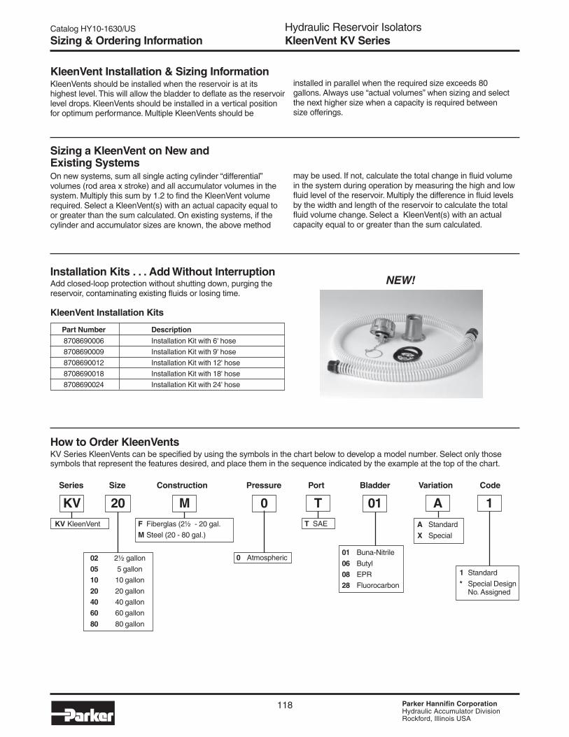
Catalog HY10-1630/US
118 Parker Hannifin CorporationHydraulic Accumulator DivisionRockford, Illinois USA
KleenVent Installation & Sizing InformationKleenVents should be installed when the reservoir is at itshighest level. This will allow the bladder to deflate as the reservoirlevel drops. KleenVents should be installed in a vertical positionfor optimum performance. Multiple KleenVents should be
Sizing a KleenVent on New andExisting SystemsOn new systems, sum all single acting cylinder “differential”volumes (rod area x stroke) and all accumulator volumes in thesystem. Multiply this sum by 1.2 to find the KleenVent volumerequired. Select a KleenVent(s) with an actual capacity equal toor greater than the sum calculated. On existing systems, if thecylinder and accumulator sizes are known, the above method
installed in parallel when the required size exceeds 80gallons. Always use “actual volumes” when sizing and selectthe next higher size when a capacity is required betweensize offerings.
may be used. If not, calculate the total change in fluid volumein the system during operation by measuring the high and lowfluid level of the reservoir. Multiply the difference in fluid levelsby the width and length of the reservoir to calculate the totalfluid volume change. Select a KleenVent(s) with an actualcapacity equal to or greater than the sum calculated.
How to Order KleenVentsKV Series KleenVents can be specified by using the symbols in the chart below to develop a model number. Select only thosesymbols that represent the features desired, and place them in the sequence indicated by the example at the top of the chart.
Series Size Construction Pressure Port Bladder Variation Code
1 Standard
* Special DesignNo. Assigned
KV 20 M 0 T 01 A 1F Fiberglas (2½ - 20 gal.
M Steel (20 - 80 gal.)
KV KleenVent T SAE
01 Buna-Nitrile
06 Butyl
08 EPR
28 Fluorocarbon
A Standard
X Special
02 2½ gallon
05 5 gallon
10 10 gallon
20 20 gallon
40 40 gallon
60 60 gallon
80 80 gallon
0 Atmospheric
Sizing & Ordering InformationHydraulic Reservoir IsolatorsKleenVent KV Series
Installation Kits . . . Add Without InterruptionAdd closed-loop protection without shutting down, purging thereservoir, contaminating existing fluids or losing time.
KleenVent Installation Kits
Part Number Description
8708690006 Installation Kit with 6' hose
8708690009 Installation Kit with 9' hose
8708690012 Installation Kit with 12' hose
8708690018 Installation Kit with 18' hose
8708690024 Installation Kit with 24' hose
NEW!

Catalog HY10-1630/US
PageHydraulic AccumulatorsIntroduction
1 Parker Hannifin CorporationHydraulic Accumulator DivisionRockford, Illinois USA
Introduction ............................................................................................................................................................ 2Certifications .......................................................................................................................................................... 3Accumulator Selection Guide (Making the Right Choice) ............................................................................... 4-15inPHorm™ Software............................................................................................................................................. 16Application Data Sheet ........................................................................................................................................ 17Piston Accumulators – A & B Series .............................................................................................................. 19-64
• Series 3000 Piston Accumulators and Gas Bottles (3000 PSI & 207 Bar Metric) .............................................................. 22-39• Series 3000 Non-ASME (7” Bore) ..................................................................................................................................... 32-33• 2000 PSI (12” Bore) .......................................................................................................................................................... 34-35• Series 4000 Piston Accumulators and Gas Bottles (4000 PSI & 276 Bar Metric) .............................................................. 40-49• Series 5000 Piston Accumulators and Gas Bottles (5000 PSI & 345 Bar Metric) .............................................................. 50-64
Bladder Accumulators – BA, BG, & BT Series ............................................................................................... 65-80• Dimensions ........................................................................................................................................................................... 68• Options ............................................................................................................................................................................. 74-76• Ordering Information ......................................................................................................................................................... 78-79
Diaphragm Accumulators – AD Series ........................................................................................................... 81-86• Dimensions ........................................................................................................................................................................... 83• Options .................................................................................................................................................................................. 84• Ordering Information .............................................................................................................................................................. 85
Inline Pulse-Tone™ Hydraulic Shock Suppressors ..................................................................................... 87-100• Dimensions ...................................................................................................................................................................... 92-96• Ordering Information .............................................................................................................................................................. 97• Accessories ...................................................................................................................................................................... 98-99
Gas Bottles – GB Series ............................................................................................................................. 101-104Accumulator Accessories........................................................................................................................... 105-114
• Charging & Gauging Assemblies .................................................................................................................................. 106-111• Unloading Valves ................................................................................................................................................................. 111• Bladder Accumulator Repair Tools ....................................................................................................................................... 112• Port Adaptors ...................................................................................................................................................................... 112• Mounting Accessories & Brackets ................................................................................................................................. 113-114
KleenVent Reservoir Isolators – KV Series ................................................................................................ 115-118Greerolators ....................................................................................................................................................... 119Pulse-Tones ........................................................................................................................................................ 120SurgeKushons – SK Series ......................................................................................................................... 121-128
• Dimensions .................................................................................................................................................................. 126-127• Options & Ordering Information ........................................................................................................................................... 128
Sizing Data .................................................................................................................................................. 129-135Applications ................................................................................................................................................ 136-138Application Data Sheet ...................................................................................................................................... 139Installation and Maintenance Instructions ................................................................................................. 141-158
• Hydraulic Piston Accumulators ..................................................................................................................................... 141-146• Hydraulic Piston Accumulators – CE Marking ............................................................................................................... 147-156• Bladder Accumulators .................................................................................................................................................. 157-164• Bladder Accumulators – CE Marking ............................................................................................................................ 165-178• Diaphragm Accumulators ............................................................................................................................................. 179-182• Inline Pulse-Tone™ ...................................................................................................................................................... 183-185• Gas Chucks ......................................................................................................................................................................... 186
Model Number Cross Reference ................................................................................................................. 187-200Offer of Sale ........................................................................................................................................................ 208
! WARNINGFAILURE OR IMPROPER SELECTION OR IMPROPER USE OF THE PRODUCTS AND/OR SYSTEMS DESCRIBED HEREIN OR RELATED ITEMS CAN CAUSE DEATH,PERSONAL INJURY AND PROPERTY DAMAGE.
This document and other information from Parker Hannifin Corporation, its subsidiaries and authorized distributors provide product and/or system options for further investigation by usershaving expertise. It is important that you analyze all aspects of your application, including consequences of any failure and review the information concerning the product or system in thecurrent product catalog. Due to the variety of operating conditions and applications for these products or systems, the user, through its own analysis and testing, is solely responsible formaking the final selection of the products and systems and assuring that all performance, safety and warning requirements of the application are met.
The products described herein, including without limitation, product features, specifications, designs, availability and pricing, are subject to change by Parker Hannifin Corporation andits related companies at any time without notice.
Contents
© Copyright 2003, Parker Hannifin Corporation. All rights reserved.

Catalog HY10-1630/US
ntentsHydraulic AccumulatorsIntroduction
2 Parker Hannifin CorporationHydraulic Accumulator DivisionRockford, Illinois USA
Parker Accumulators…• Provide an auxiliary power source by
holding supplemental power to beused during peak periods. This allowsthe use of smaller pumps, motors, andreservoirs reducing installation andoperating costs.
• Protect hydraulic systems and circuitcomponents from damage due tothermal expansion and contraction ina closed system.
• Make up changes in fluid volume toassure a positive pressure.
• Reduce costly damage to pipingsystems, fittings, and gauges byabsorbing hydraulic line shocks.
• Supply emergency fail-safe power tocomplete a work safety cycle in theevent of a pump or electric powerfailure.
• Hold necessary high pressure for longperiods of time while preventing oiloverheating, reducing pump wear, andsaving energy.
• Dispense lubricants in a slow, constantrate to critical equipment wear areas.
Parker Accumulators are designed to optimize the performance of your hydraulic system,while adding safeguards that prolong equipment life. Reduced operating costs and savingsfrom less downtime and maintenance are the benefits.
Applications
Typical Applications• Construction & Mining Equipment –
emergency backup for steering, brake,and pilot circuits.
• Hydrostatic Drives – shock absorptionwhen changing directions.
• Injection Molding & Die Casting – highpressure and flows in a short timeperiod.
• Plunger & Diaphragm Pumps –reduces pump pulsations.
• Fork Lifts & Cherry Pickers – pressurespike dampening.
• Machine Tools – maintains pressure,reduces pump size.
• Transportation Vehicles – suspensionsystems and braking systems.
• Turbine Engines – oil supply forlubrication.
• Winches – maintaining line tension.
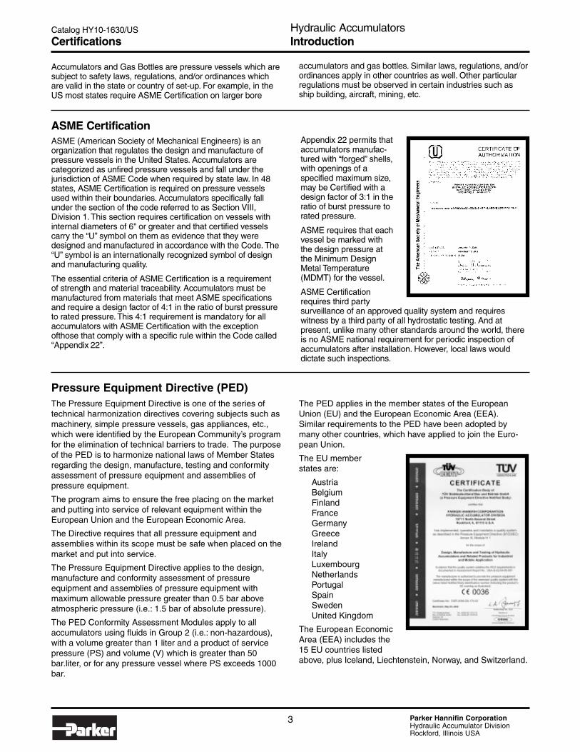
Catalog HY10-1630/US
PageHydraulic AccumulatorsIntroduction
3 Parker Hannifin CorporationHydraulic Accumulator DivisionRockford, Illinois USA
Certifications
Accumulators and Gas Bottles are pressure vessels which aresubject to safety laws, regulations, and/or ordinances whichare valid in the state or country of set-up. For example, in theUS most states require ASME Certification on larger bore
ASME CertificationASME (American Society of Mechanical Engineers) is anorganization that regulates the design and manufacture ofpressure vessels in the United States. Accumulators arecategorized as unfired pressure vessels and fall under thejurisdiction of ASME Code when required by state law. In 48states, ASME Certification is required on pressure vesselsused within their boundaries. Accumulators specifically fallunder the section of the code referred to as Section VIII,Division 1. This section requires certification on vessels withinternal diameters of 6" or greater and that certified vesselscarry the “U” symbol on them as evidence that they weredesigned and manufactured in accordance with the Code. The“U” symbol is an internationally recognized symbol of designand manufacturing quality.
The essential criteria of ASME Certification is a requirementof strength and material traceability. Accumulators must bemanufactured from materials that meet ASME specificationsand require a design factor of 4:1 in the ratio of burst pressureto rated pressure. This 4:1 requirement is mandatory for allaccumulators with ASME Certification with the exceptionofthose that comply with a specific rule within the Code called“Appendix 22”.
Appendix 22 permits thataccumulators manufac-tured with “forged” shells,with openings of aspecified maximum size,may be Certified with adesign factor of 3:1 in theratio of burst pressure torated pressure.
ASME requires that eachvessel be marked withthe design pressure atthe Minimum DesignMetal Temperature(MDMT) for the vessel.
ASME Certificationrequires third partysurveillance of an approved quality system and requireswitness by a third party of all hydrostatic testing. And atpresent, unlike many other standards around the world, thereis no ASME national requirement for periodic inspection ofaccumulators after installation. However, local laws woulddictate such inspections.
Pressure Equipment Directive (PED)The Pressure Equipment Directive is one of the series oftechnical harmonization directives covering subjects such asmachinery, simple pressure vessels, gas appliances, etc.,which were identified by the European Community’s programfor the elimination of technical barriers to trade. The purposeof the PED is to harmonize national laws of Member Statesregarding the design, manufacture, testing and conformityassessment of pressure equipment and assemblies ofpressure equipment.
The program aims to ensure the free placing on the marketand putting into service of relevant equipment within theEuropean Union and the European Economic Area.
The Directive requires that all pressure equipment andassemblies within its scope must be safe when placed on themarket and put into service.
The Pressure Equipment Directive applies to the design,manufacture and conformity assessment of pressureequipment and assemblies of pressure equipment withmaximum allowable pressure greater than 0.5 bar aboveatmospheric pressure (i.e.: 1.5 bar of absolute pressure).
The PED Conformity Assessment Modules apply to allaccumulators using fluids in Group 2 (i.e.: non-hazardous),with a volume greater than 1 liter and a product of servicepressure (PS) and volume (V) which is greater than 50bar.liter, or for any pressure vessel where PS exceeds 1000bar.
The PED applies in the member states of the EuropeanUnion (EU) and the European Economic Area (EEA).Similar requirements to the PED have been adopted bymany other countries, which have applied to join the Euro-pean Union.
The EU memberstates are:
AustriaBelgium DenmarkFinlandFranceGermanyGreeceIrelandItalyLuxembourgNetherlandsPortugalSpainSwedenUnited Kingdom
The European EconomicArea (EEA) includes the15 EU countries listedabove, plus Iceland, Liechtenstein, Norway, and Switzerland.
accumulators and gas bottles. Similar laws, regulations, and/orordinances apply in other countries as well. Other particularregulations must be observed in certain industries such asship building, aircraft, mining, etc.

Catalog HY10-1630/US
ntentsHydraulic AccumulatorsIntroduction
4 Parker Hannifin CorporationHydraulic Accumulator DivisionRockford, Illinois USA
Accumulator Selection Guide
Hydro-pneumatic accumulatorsare the most widely used type ofaccumulator in industrial andmobile hydraulic systems. Theyuse compressed gas to applyforce to hydraulic fluid. Identicalin their operating principle,Parker’s piston, bladder anddiaphragm accumulators usedifferent mechanisms to sepa-rate the gas from the fluid. It isthis difference – and the result-ing performance characteristics– which determines their suit-ability for different applications.The correct selection andapplication of different styleaccumulators is examined in thefollowing pages.
Parker’s hydro-pneumatic accumulators regulate the performance of a hydraulicsystem by providing an additional volume of system fluid, pressurized by anexternal gas supply.
A correctly specified accumulator can:
• reduce shock effects in a system resulting from inertia orexternal mechanical forces
• maintain system pressure by compensating for pressureloss due to leakage
• provide a back-up supply of hydraulic energy to maintain aconstant flow when system demand is greater than pump delivery.
In industrial applications, three types of hydro-pneumatic accumulators are widelyused – the piston type, bladder type and diaphragm type. Each has particularadvantages and limitations which should be considered when selecting anaccumulator for a specific application.
Piston accumulators offer greater efficiency and flexibility in most applications, dueto their wider range of sizes. Parker’s piston accumulators feature a patentedfive-blade V-O-ring which maintains full contact between the piston and the bore,without rolling. Sealing remains effective even under rapid cycling at high operatingpressures.
Bladder/Diaphragm accumulators are generally preferred for applications whererapid cycling, high fluid contamination and fast response times are required. Theyprovide excellent gas/fluid separation.
Piston Advantages• extremely high flow rates• high/low temperature tolerance• high compression ratios• withstands external forces• unlimited sizes/mounting• work well with gas bottles• fully serviceable
Bladder Advantages• dirt tolerant• universal application• safety• quick response• works well on water,
low lubricity fluids• fully serviceable
Diaphragm Advantages• lightweight, compact
• simple, cost effective• dirt tolerant• quick response
Making the Right Choice

Catalog HY10-1630/US
PageHydraulic AccumulatorsIntroduction
5 Parker Hannifin CorporationHydraulic Accumulator DivisionRockford, Illinois USA
Accumulator Selection Guide
Design Features and Construction
Bladder AccumulatorsGreer bladder accumulators feature anon-pleated, flexible rubber bladderhoused within a steel shell. The openend of the bladder is attached to theprecharging valve at the gas end of theshell. A poppet valve, normally heldopen by spring pressure, regulatesfluid flow through the hydraulic port.Greer’s bladder accumulators areavailable as either top or bottomrepairable units, for optimum flexibility.
Diaphragm AccumulatorsParker diaphragm accumulatorsfeature a one piece moldeddiaphragm which is mechanicallysealed to the high strength metal shell.The flexible diaphragm providesexcellent gas and fluid separation.A button molded to the bottom of thediaphragm prevents the diaphragmfrom being extruded out the hydraulicport. The non-repairable electron-beam welded construction reducessize, weight, and ultimately cost.
The bladder/diaphragm is charged witha dry inert gas, such as: nitrogen, to aset precharge pressure determined bythe system requirements. As systempressure fluctuates, the bladder/diaphragm expands and contracts todischarge fluid from, or allow fluid into,the accumulator shell.
Piston AccumulatorsParker piston accumulators consist ofa cylindrical body, sealed by a gas capand charging valve at the gas end, andby a hydraulic cap at the hydraulic end.A lightweight piston separates the gasside of the accumulator from thehydraulic side.
As with the bladder/diaphragmaccumulator, the gas side is chargedwith nitrogen to a predeterminedpressure. Changes in system pressurecause the piston to rise and fall,allowing fluid to enter or forcing it to bedischarged from the accumulator body.
ChargingValve
Bladder
Shell
Poppet
Spring
HydraulicPort
ChargingValve
Body
Gas Cap
Piston
HydraulicCap
Gas
Shell
ChargingValve
Diaphragm Button
Fluid Port
BLADDER DIAPHRAGM PISTON
Fig. 1 Typical bladder, diaphragm and piston accumulators

Catalog HY10-1630/US
ntentsHydraulic AccumulatorsIntroduction
6 Parker Hannifin CorporationHydraulic Accumulator DivisionRockford, Illinois USA
Accumulator Selection Guide
Stage (a)The accumulator is empty, andneither gas nor hydraulic sides arepressurized.
Stage (b)The accumulator is precharged.
Stage (c)The hydraulic system is pressurized.System pressure exceeds prechargepressure, and fluid flows into theaccumulator.
Stage (d)System pressure peaks. The accumu-lator is filled with fluid to its designcapacity. Any further increase inhydraulic pressure would be preventedby a relief valve in the system.
Stage (e)System pressure falls. Prechargepressure forces fluid from the accumu-lator into the system.
Stage (f)Minimum system pressure is reached.The accumulator has discharged itsdesign maximum volume of fluid backinto the system.
Operation
Fig 2 Operating conditions of bladder, piston and diaphragm accumulators
(A) (B) (C) (D) (E) (F)
Gas

Catalog HY10-1630/US
PageHydraulic AccumulatorsIntroduction
7 Parker Hannifin CorporationHydraulic Accumulator DivisionRockford, Illinois USA
Compression System Recommended Fluid OutputRatio Pressure, Precharge, GPM
PSI PSI
max min Bladder Piston Bladder Piston
1.5 3000 2000 1800 1900 2.79 3.00
2 3000 1500 1350 1400 4.23 4.41
3 3000 1000 900 900 5.70 5.70
6 3000 500 ❋ 400 ❋ 6.33
Accumulator Selection Guide
When selecting an accumulator for a particular application,both system and performance criteria should be considered.To ensure long and satisfactory service life, the followingfactors should be taken into account.
• Failure mode • Output volume
• Flow rate • Fluid type
• Response time • Shock suppression
• High frequency cycling • Mounting position
• External forces • Sizing information
• Certification • Safety
• Temperature effect
Failure ModesIn certain applications, a sudden failure may be preferable toa gradual failure. A high-speed machine, for example, whereproduct quality is a function of hydraulic system pressure.Because sudden failure is detected immediately, scrap isminimized, whereas a gradual failure might mean thatproduction of a large quantity of sub-standard product couldoccur before the failure became apparent.
A bladder/diaphragm accumulator would be most suitable forthis application.
Conversely, where continuous operation is paramount andsudden failure could be detrimental as, for example, in abraking or steering circuit on mobile equipment, a progres-sive failure mode is desirable. In this application, a pistonaccumulator would be appropriate.
Output VolumeThe maximum sizes available of each type of accumulatordetermine the limits of their suitability where large outputvolumes are required. There are, however, several methodsof achieving higher output volumes than standard accumula-tor capacities suggest - see Large/ Multiple Accumulators,page 11.
Table 1 compares typical fluid outputs for Parker’s 10 gallonpiston and bladder accumulators operating isothermally asauxiliary power sources over a range of minimum systempressures. The higher precharge pressures recommendedfor piston accumulators result in higher outputs than fromcomparable bladder accumulators. Also, bladder accumula-tors are not generally suitable for compression ratios greaterthan 4:1, as these could result in excessive bladder deforma-tion.
Piston accumulators have an inherently higher outputrelative to their overall dimensions, which may be critical inlocations where space is limited. Piston accumulators areavailable in a choice of diameters and lengths for a givencapacity, whereas bladder and diaphragm accumulators arefrequently offered in only one size per capacity, and fewersizes are available. Piston accumulators can also be built tocustom lengths for applications in which available space iscritical.
Flow RateTable 2 shows typical maximum flow rates for Parker’saccumulator styles in a range of sizes.
The larger standard bladder designs are limited to 220 GPM,although this may be increased to 600 GPM using a highflowport. The poppet valve controls flow rate, with excessive flowcausing the poppet to close prematurely. Flow rates greaterthan 600 GPM may be achieved by mounting severalaccumulators on a common manifold – see Large/MultipleAccumulators, page 11.
For a given system pressure, flow rates for piston accumula-tors generally exceed those for bladder designs. Flow islimited by piston velocity, which should not exceed 10 ft/sec.to avoid piston seal damage. In high-speed applications,high seal contact temperatures and rapid decompression ofnitrogen that has permeated the seal itself, can causeblisters, cracks and pits in the seal surface. In this type ofapplication a bladder style accumulator would be bettersuited.
Accumulator Selection Table 1: Relative Outputs of a 40 litre Accumulator
Table 2: Maximum RecommendedAccumulator Flow Rates
GPM at 3000 PSI
BladderPiston Bladder Diaphragm Piston Bladder High DiaphragmBore Capacity Capacity Std. Flow
2 1 qt. .5-10 cu. in. 100 40 11
3 1 gal. 20-85 cu. in. 220 150 26
4 2.5 gal. 120-170 cu. in. 397 220 600 42
6 and 818 220 600
7 Larger 1199 220 600
9 1982 220 600
12 3450
❋ Below required minimum operating ratio of 4:1.

Catalog HY10-1630/US
ntentsHydraulic AccumulatorsIntroduction
8 Parker Hannifin CorporationHydraulic Accumulator DivisionRockford, Illinois USA
Installing a Greer 1 gallon piston accumulator at the valvereduces the transient to 100 PSI over relief valve setting(medium trace).
Substituting a 1 gal. bladder accumulator further reduces thetransient to 80 PSI over relief valve setting (dark trace), animprovement of only 20 PSI and of little practical signifi-cance.
Example 2A second, similar test using 0.625 in. tubing and a reliefvalve setting of 2650 PSI (Fig. 5) results in a pressure spikeof 2011 PSI over relief valve setting without an accumulator(light trace).
A Parker piston accumulator reduces the transient to 107PSI over relief valve setting (medium trace), while a bladderaccumulator achieves a transient of 87 PSI over relief valvesetting (dark trace). The difference between accumulatortypes in shock suppression is again negligible.
Fluid TypeBladder/Diaphragm accumulators are more resistant todamage caused by contamination of the hydraulic fluid thanpiston types. While some risk exists from contaminantstrapped between the bladder and the shell, a higher risk offailure exists from the same contaminants acting on thepiston seal.
Bladder accumulators are usually preferred to piston typeaccumulators for water service applications. Water systemstend to carry more solid contaminants and lubrication is poor.Both the piston and bladder type units require some type ofpreparation to resist corrosion on the wetted surfaces.
Piston accumulators are preferred for systems using exoticfluids or where extremes of temperature are experienced as,compared to bladders. Piston seals are more easily moldedin the required special compounds, and may be lessexpensive.
Response TimeIn theory, bladder and diaphragm accumulators shouldrespond more quickly to system pressure variations thanpiston types. There is no static friction to be overcome aswith a piston seal, and there is no piston mass to be acceler-ated and decelerated. In practice, however, the difference inresponse is not great, and is probably insignificant in mostapplications.
This applies equally in servo applications, as only a smallpercentage of servos require response times of 25ms orless. This is the point where the difference in responsebetween piston and bladder accumulators becomes signifi-cant. Generally, a bladder accumulator should be used forapplications requiring less than 25ms response time, andeither accumulator type for a response of 25ms or greater.
ShockSuppressionShock control does notnecessarily demand abladder/diaphragmaccumulator.
Example 1A test circuit (Fig.3)includes a control valvesituated 118 ft. from apump supplying fluid at29.6 GPM. The circuituses 1.25 in. tubing andthe relief valve is set toopen at 2750 PSI.Shutting the control valve(Fig.4) produces apressure spike of 385 PSIover relief valve setting(light trace).
4000
2000
0
Pre
ssur
e –
PS
I
0 1000 2000Time – ms
No accumulator in circuit
Piston accumulator
Bladder accumulator
4000
2000
0
Pre
ssur
e –
PS
I
0 1000 2000Time – ms
No accumulator in circuit
Piston accumulator
Bladder accumulator
Tubing lengthmakespump-to-servovalvedistance 36m.
Fig.5 Shock wave test results – Example 2
Fig.4 Shock wave test results – Example 1
Accumulator Selection Guide
Fig.3 Test circuit to generateand measure shock waves ina hydraulic system

Catalog HY10-1630/US
PageHydraulic AccumulatorsIntroduction
9 Parker Hannifin CorporationHydraulic Accumulator DivisionRockford, Illinois USA
Accumulator Selection Guide
High Frequency CyclingHigh-frequency system pressure cycling can cause a pistonaccumulator to ‘dither’, with the piston cycling rapidly backand forth in a distance less than its seal width.
Over an extended period, this condition may cause heatbuild-up under the seal due to lack of lubrication, resulting inseal and bore wear. For high frequency dampening applica-tions, therefore, a bladder/diaphragm accumulator isgenerally more suitable.
Mounting PositionThe optimum mounting position for any accumulator isvertical, with the hydraulic port downwards. Piston modelscan be mounted horizontally if the fluid is kept clean but, ifsolid contaminants are present or expected in significantamounts, horizontal mounting can result in uneven oraccelerated seal wear.
A bladder accumulator may also be mounted horizontally, butuneven wear on the top of the bladder as it rubs against theshell while floating on the fluid can reduce its service life andeven cause permanent distortion. The extent of the damagewill depend upon fluid cleanliness, cycle rate, and compres-sion ratio (i.e. maximum system pressure divided by mini-mum system pressure). In extreme cases, fluid can betrapped away from the hydraulic port (Fig.6), reducingoutput, or the bladder may become elongated, forcing thepoppet valve to close prematurely.
External ForcesAny application subjecting an accumulator to acceleration,deceleration or centrifugal force may have a detrimentaleffect on its operation, and could cause damage to a bladderaccumulator. Forces along the axis of the tube or shellnormally have little effect on a bladder accumulator but maycause a variation in gas pressure in a piston type because ofthe mass of the piston.
Fig.6 A horizontally-mounted bladder accumulator can trapfluid away from the hydraulic valve
Fig.7
Perpendicular forcecauses the mass of thefluid to displace thebladder
Forces perpendicular to an accumulator’s axis should notaffect a piston model, but fluid in a bladder accumulator maybe thrown to one side of the shell (Fig.7), displacing thebladder and flattening and lengthening it. In this condition,fluid discharge could cause the poppet valve to pinch and cutthe bladder. Higher precharge pressures increase theresistance of the bladder to the effects of perpendicularforces.
Acceleration
Sizing InformationAccurate sizing of an accumulator is critical if it is to delivera long and reliable service life. Information and workedexamples are shown in the sizing section of this catalog, oraccumulator size can be calculated automatically by enteringapplication details into Parker’s inPHorm software selectionprogram (see page 16). Please contact your local distributorfor details, or contact us at www.parker.com/accumulator.
CertificationAccumulators are frequently required to conform to domesticor international certification. These requirements range fromsimple design factors to elaborate materials testing andinspection procedures carried out by an external agency.Most of the accumulators in Parker’s piston, bladder, ordiaphragm ranges are available with certification to meet allmajor U.S. and most major European standards.
SafetyHydro-pneumatic accumulators should always be used inconjunction with a safety block, to enable the accumulator tobe isolated from the circuit in an emergency or for mainte-nance purposes.

Catalog HY10-1630/US
ntentsHydraulic AccumulatorsIntroduction
10 Parker Hannifin CorporationHydraulic Accumulator DivisionRockford, Illinois USA
Accumulator Selection Guide
Remote gas storage offers installation flexibility where theavailable space or position cannot accommodate an accu-mulator of the required size. A smaller accumulator may beused in conjunction with a Parker auxiliary gas bottle, whichcan be located elsewhere (Fig.8).
The gas bottle is sized by the formula:
For Piston Accumulators:
gas bottle size = accumulator size -
(required output from accumulator x 1.1)
For Bladder Type Accumulators:
gas bottle size = accumulator size -
(required output from accumulator x 1.25)
For example, an application that calls for a 30 gallonaccumulator may only actually require 8 gallons of fluidoutput. This application could therefore be satisfied with a 10gallon accumulator and a 20 gallon gas bottle.
Gas bottle installations may use either bladder or pistonaccumulators, subject to the following considerations.
• Any accumulator used with remote gas storage shouldgenerally have the same size port at the gas end as at thehydraulic end, to allow an unimpeded flow of gas to andfrom the gas bottle. The gas bottle will have an equivalentport in one end and a gas charging valve at the other.
• A piston accumulator should be carefully sized to preventthe piston bottoming at the end of the cycle. Bladderdesigns should be sized to prevent filling to more than75% full.
• Bladder installations require a special device called atransfer barrier at the gas end, to prevent extrusion of thebladder into the gas bottle piping. The flow rate betweenthe bladder transfer barrier and its gas bottle will berestricted by the neck of the transfer barrier tube.
• Because of the above limitations, piston accumulators aregenerally preferred to bladder types for use in gas bottleinstallations.
• Diaphragm style accumulators are normally not used inconjunction with gas bottles.
Accumulator manifold showing three gas bottles attached toa transfer barrier type piston accumulator.
Fig.8
An accumulator can beused with a remote gasbottle where space iscritical
Gas Bottle Installations

Catalog HY10-1630/US
PageHydraulic AccumulatorsIntroduction
11 Parker Hannifin CorporationHydraulic Accumulator DivisionRockford, Illinois USA
Accumulator Selection Guide
Large/Multiple AccumulatorsThe requirement for an accumulator with an output of morethan 50 gallons cannot usually be met by a single accumula-tor, because larger piston designs are relatively rare andexpensive, and bladder designs are not generally available inthese sizes. The requirement can, however, be met usingone of the multiple-component installations shown inFigs. 9 and 10.
The installation in Fig. 9 consists of several gas bottlesserving a single piston accumulator through a gas manifold.The accumulator portion may be sized outside of thelimitations of the sizing formula on page 10, but should notallow the piston to strike the caps repeatedly while cycling.The larger gas volume available with this configurationallows a relatively greater piston movement - and hence fluidoutput - than with a conventionally sized single accumulator.A further advantage is that, because of the large precharge‘reservoir’, gas pressure is relatively constant over the fulldischarge cycle of the accumulator. The major disadvantageof this arrangement is that a single seal failure could drainthe whole gas system.
The installation in Fig.10 uses several accumulators, ofpiston or bladder design, mounted on a hydraulic manifold.Two advantages of multiple accumulators over multiple gasbottles are that higher unit fluid flow rates are permissible,and a single leak will not drain precharge pressure from theentire system.
A potential disadvantage is that, where piston accumulatorsare used, the piston with the least friction will move first andcould occasionally bottom on the hydraulic end cap. How-ever, in a slow or infrequently used system, this would be oflittle significance. Fig.9 (below)
Several gas bottles can supplyprecharge pressure to a singleaccumulator
Fig.10 (above)Multiple accumulatorsmanifolded together offerhigh system flow rates
FluidGas manifold
Fluid manifold

Catalog HY10-1630/US
ntentsHydraulic AccumulatorsIntroduction
12 Parker Hannifin CorporationHydraulic Accumulator DivisionRockford, Illinois USA
Precharging ProcessCorrect precharging involves accurately filling the gas side ofan accumulator with a dry, inert gas such as nitrogen, beforeadmitting fluid to the hydraulic side.
It is important to precharge an accumulator to the correctspecified pressure. Precharge pressure determines thevolume of fluid retained in the accumulator at minimumsystem pressure. In an energy storage application, abladder/diaphragm accumulator is typically precharged to90% of minimum system pressure, and a piston accumulatorto 95% of minimum system pressure at the system operat-ing temperature.
The ability to correctly carry out and maintain precharging isan important factor when choosing the type of accumulatorfor an application.
Bladder accumulators are far more susceptible to damageduring precharging than piston types. Before prechargingand entering in service, the inside of the shell should belubricated with system fluid. This fluid acts as a cushion, andlubricates and protects the bladder as it expands. Whenprecharging, the first 50 PSI of nitrogen should be introducedslowly. Failure to follow this precaution could result inimmediate bladder failure: high pressure nitrogen, expandingrapidly and thus cold, could form a channel in the foldedbladder, concentrating at the bottom.
The chilled, brittlerubber, expandingrapidly would theninevitably rupture(Fig. 11).
The bladder could alsobe forced under thepoppet, resulting in acut. (Fig.12).
Close attention shouldbe paid to operatingtemperature duringprecharging, as a rise intemperature will cause acorresponding increasein pressure which couldthen exceed theprecharge limit.
Little damage can occurwhen precharging orchecking the prechargeon a piston accumulator,but care should be takento make sure theaccumulator is void of allfluid to prevent gettingan incorrect reading onthe precharge.
Accumulator Selection Guide
Fig.11
Starburst rupture caused byloss of bladder elasticity
Excessively High PrechargeExcessive precharge pressure or a reduction in the minimumsystem pressure without a corresponding reduction inprecharge pressure may cause operating problems ordamage to accumulators.
With excessive precharge pressure, a piston accumulatorwill cycle between stages (e) and (b) of Fig.2 see page 4,and the piston will travel too close to the hydraulic end cap.
The piston could bottom at minimum system pressure,reducing output and eventually damaging the piston andpiston seal. The piston can often be heard bottoming,warning of impending problems.
An excessive precharge in a bladder accumulator can drivethe bladder into the poppet assembly when cycling betweenstages (e) and (b). This could cause fatigue failure of thepoppet spring assembly, or even a pinched and cut bladder,should it become trapped beneath the poppet as it is forcedclosed (Fig.12). Excessive precharge pressure is the mostcommon cause of bladder failure.
Excessively Low PrechargeExcessively low precharge pressure or an increase insystem pressure without a corresponding increase inprecharge pressure can also cause operating problems andsubsequent accumulator damage. With no precharge in apiston accumulator, the piston will be driven into the gas endcap and will often remain there. Usually, a single contact willnot cause any damage, but repeated impacts will eventuallydamage the piston and seal.
Conversely, for a bladder accumulator, too low or noprecharge can have rapid and severe consequences. Thebladder will be crushed into the top of the shell and canextrude into the gas stem and be punctured (Fig13).
This condition is known as “pick out”. One such cycle issufficient to destroy a bladder. Overall, piston accumulatorsare generally more tolerant of careless precharging.
Fig.13
Fluid entering anun-precharged bladderaccumulator hasforced the bladder intothe gas stem
Fig.12
C-shaped cut shows thatbladder has been trappedunder poppet

Catalog HY10-1630/US
PageHydraulic AccumulatorsIntroduction
13 Parker Hannifin CorporationHydraulic Accumulator DivisionRockford, Illinois USA
Accumulator Selection Guide
Monitoring Piston AccumulatorPrechargeSeveral methods can be used to monitor theprecharge pressure of Parker’s piston accumulators.Note that, in Figs.14b and 14c, flat pistons must beused to enable the sensors to register their positions.
Fig.14a Pressure transducer measures actual prechargepressure of shut down system
Fig.14b Position sensor can provide continuous indicationof precharge pressure
Fig.14c Hall Effect sensor registers proximity of piston toend cap
• In applications where anaccumulator is coupled toa gas bottle, a Hall Effectproximity sensor can beinstalled in the accumulatorgas end cap (Fig.14c) todetect when the pistoncomes within .050 inch ofthe cap. This system wouldprovide a warning whenprecharge pressure hasdropped and remedial actionshould be taken.
• With the hydraulic systemoperating. A piston positionsensor is installed in thehydraulic end cap (Fig.14b)and connected to anelectronic measuringsystem. With an accurateinitial precharge and aftersufficient system operationto ensure thermal stability,the electronics can becalibrated to provide acontinuous and accurateread-out of prechargepressure.
Fluid
Pressuretransducer
Hall Effectproximitysensor
Fluid
Pressuretransducer
Sonar absoluteposition sensor
Fluid
Pressuretransducer
• With the hydraulic systemshut down. A pressuretransducer or gaugelocated in the gas end cap(Fig.14a) indicates the trueprecharge pressure afterthe hydraulic system hascooled and the accumulatorhas emptied of fluid.

Catalog HY10-1630/US
ntentsHydraulic AccumulatorsIntroduction
14 Parker Hannifin CorporationHydraulic Accumulator DivisionRockford, Illinois USA
Accumulator Selection Guide
• In some instances, it is extremelyimportant to know the exact locationof the piston inside the accumulator.By using a linear displacementtransducer (LDT), this can beaccomplished. Positions as well asvelocities can be determined by theuse of this unit.
An LDT works by sending a signaldown the probe. This signal is thenreflected by a magnet attached to arod and piston assembly. The LDTrecords the amount of time betweensending and receiving the reflectedsignal and then calculates theposition of the piston. Multiplesignals will allow the unit to calculatevelocity. The result of using this unitwill allow the user to know the exactcubic inches of fluid in the accumula-tor as well as the flow rate of thefluid.
• A proximity or reed switch can be usedin applications where it is desirable toknow when the piston is approachingthe gas cap of the accumulator or todetect a low precharge. When the rodis detected by the reed or proximityswitch, the switch could be set up tosend out a warning signal.
When used with a pressure switch, itcould detect a low precharge.
In some instances two reed orproximity switches could be installedon the housing. It could be requiredthat the first switch is always made,assuring us that the precharge is nottoo high; if the second switch is made,it would tell us that the precharge is tolow.
The position of the piston can bedetected a fraction of an inch toseveral inches before it reaches theend cap. Fig.14d Proximity switches can sense the position of an
approaching piston
Fig.14e Linear Displacement Transducers (LDT) canaccurately detect both piston location and velocity
Hyd. Port.
Pressure switch
Proximity switch orReed switch
Magnet
Gas valve
S.S.Housing
Gas Bottle
(only if Reedswitch is used
.)
Rod
Hyd. Port.
Magnet
Probe
LDT

Catalog HY10-1630/US
PageHydraulic AccumulatorsIntroduction
15 Parker Hannifin CorporationHydraulic Accumulator DivisionRockford, Illinois USA
Accumulator Selection Guide
Accumulator failure is generally defined as inability toaccept and exhaust a specified amount of fluid whenoperating over a specific system pressure range.Failure often results from an unwanted loss or gain ofprecharge pressure.
It cannot be too highly stressed that correctprecharge pressure is the most important factor inprolonging accumulator life.
If maintenance of precharge pressure and relief valvesettings is neglected, and if system pressures areadjusted without making corresponding adjustments toprecharge pressures, shortened service life will result.
Bladder AccumulatorsBladder/Diaphragm accumulator failure occurs rapidlyfrom bladder/diaphragm rupture (Fig.15). Rupturecannot be predicted because the intact bladder ordiaphragm is essentially impervious to gas or fluidseepage; no measurable gas or fluid leakage throughthe bladder or diaphragm precedes failure.
Piston AccumulatorsPiston Accumulator failure generally occurs in oneofthe following gradual modes.
Fluid Leaks to the Gas SideThis failure, sometimes called dynamic transfer,normally takes place during rapid cycling operationsafter considerable time in service. The worn piston sealcarries a small amount of fluid into the gas side witheach stroke.
As the gas side slowly fills with fluid, prechargepressure rises and the accumulator stores and ex-hausts decreasing amounts of fluid. The accumulatorwill totally fail when precharge pressure equalsmaximum hydraulic system pressure. At that point, theaccumulator will accept no further fluid. Because therise in precharge pressure can be measured (Fig.15a),failure can be predicted and repairs effected beforetotal failure occurs.
ConclusionsA correctly specified Parker accumulator, installed and maintained in accor-dance with the guidelines contained in this catalog, will give many years oftrouble-free use. The combination of clean system fluid and accurateprecharging will prevent most of the common fault conditions described here,and will contribute to the long life and high operating efficiency of the wholehydraulic system.
Gas LeakagePrecharge may be lost as gas slowly bypasses damagedpiston seals. Seal deterioration occurs from excessively longservice, from fluid contamination, or from a combination ofthe two. Gas can also vent directly through a defective gascore or end cap O-ring.
The reducing precharge pressure then forces progressivelyless fluid into the system. Because this gradual decrease inprecharge pressure can be measured (Fig.15b), repairs canagain be effected before total failure occurs.
Fig.15 When anaccumulatorbladder ruptures,precharge pres-sure immediatelyfalls to zero
As fluid leaks pastan accumulatorpiston, prechargepressure rises (a).
Pre
char
gepr
essu
re –
PS
I
Number of cycles
Pre
char
gepr
essu
re –
PS
I
Number of cycles (a)
Pre
char
gepr
essu
re –
PS
I
Number of cycles (b)
Failure Prevention
Gas leaking pastthe piston or valvecauses prechargepressure to fall (b)

Catalog HY10-1630/US
ntentsHydraulic AccumulatorsIntroduction
16 Parker Hannifin CorporationHydraulic Accumulator DivisionRockford, Illinois USA
Sizing and Selection Software
Parker TM Version 3.6 Softwarefor Accumulator Division ProductsMakes Sizing and Selection Easy
Parker offers leading edge application assistance with its inPHorm™
for Accumulators, Version 3.6. This program allows you to select theproper Parker accumulator product for your application. Using inPHormwill increase your efficiency and minimize the engineering time requiredto design in accumulators.
This updated version of inPHorm for Accumulators is written for usewith Windows95 and later versions, which makes it extremely userfriendly. You can use the program to develop a model number. inPHormfor Accumulators guides you through the selection process, performsthe calculations, and eases the process of sorting through catalogdrawings, charts and tables. You can also employ the “Rapid Selection”module to build a model number based on a selection of options. In eithercase, you can view a dimensioned drawing, generate a print or DXF fileand even create a quote request or order form.
“Advisor” options within the program offer additional assistance withspecial modifications and design considerations. During any portion ofthe program, reference material can be accessed or printed for futureuse.
inPHorm for Accumulators is also available on the web atwww.parker.com/accumulator.
For further information or to order aCD, call your local Parker distributoror contact us at (815) 636-4100.
System Highlights• Accumulator Sizing and Selection• Parametric Drawing Creation• Input Formats:
Rapid SelectionSystematic Design
• Available Information Outputs:HPGL CAD DrawingCAD File (*.dxf)Selection Summary PrintoutRFQ/Order Sheet Printout
Rapid Selection
Systematic Design

Catalog HY10-1630/US
PageHydraulic AccumulatorsIntroduction
17 Parker Hannifin CorporationHydraulic Accumulator DivisionRockford, Illinois USA
Application Data Sheet
CUSTOMER:
ADDRESS:
CONTACT:
PHONE:
FAX:
EMAIL:
Quantity/Release: ___________________________
Quantity (Annual): ___________________________
Type (Piston or Bladder): _____________________
Bore Size (piston only): ______________________
Capacity: __________________________________
Working Pressure/Design Factor. _______________
Seal Type/Compound:________________________
Hydraulic Port:______________________________
Gas Port:__________________________________
Operating Temperature Range:_________________
System Fluid: ______________________________
Gas Valve:_________________________________
Precharge:_________________________________
Water Service? ____________________________
Plating/Coating: ____________________________
Material Type: ______________________________
Paint: ____________________________________
Switches: _________________________________
Certification: _______________________________
Special Test?_______________________________
Special Label? _____________________________
Customer Drawing Included? _________________
Customer Part # ___________________________
Envelope Restrictions: _______________________
Contact Information
Application Description/Comments
Customer Requirements
FORM-0117, Rev. 1Please fill out and fax to 815-636-4113.
For assistance, call 815-636-4100.

Catalog HY10-1630/US
ntentsHydraulic AccumulatorsIntroduction
18 Parker Hannifin CorporationHydraulic Accumulator DivisionRockford, Illinois USA
Notes

129 Parker Hannifin CorporationHydraulic Accumulator DivisionRockford, Illinois USA
Accumulator Sizing For:• Shock Suppression
• Thermal Expansion
• Pulsation Dampening
• Auxiliary Power Source
Sizing and Selection• Piston Accumulators• Bladder Accumulators• KleenVent

130 Parker Hannifin CorporationHydraulic Accumulator DivisionRockford, Illinois USA
Hydraulic AccumulatorsPiston and Bladder Type
Catalog HY10-1630/US
Sizing and Selection SoftwareParker offers leading edge application assistance, in theform of the
TM
Accumulator Sizing and SelectionSoftware (see page 16).
For manual sizing calculations, see below and on thefollowing pages.
For further engineering assistance, contactParker’s Accumulator Technical Support Groupat (815) 636-4100.
Where:
P2
= Maximum operating pressure in PSIA
P3
= Minimum operating pressure in PSIA
P1
= Pre-charge pressure required in PSIA
VW
= Volume of fluid collected or discharged by accumulator, In3
V1
= Required Accumulator volume, In3
f = Nitrogen gas constant-charging of Accumulators (see charts on pages 134-135)
n = Nitrogen gas constant-discharging of Accumulators (see charts on pages 134-135)
Note: Gas Precharge usually 100 psi below minimum pressure for Piston Accumulators*.Gas precharge is 90% of minimum pressure for Bladder Accumulators.
*90% where minimum system pressure is less than 1000 psi.
Calculations for accumulator sizing take into consideration the charge and discharge rate of the accumulator.
Auxiliary Power Source
Sizing and Selection
Accumulator Sizing for:• Shock Suppression• Thermal Expansion• Pulsation Dampening• Auxiliary Power Source
V =1
VwPP
3
1
1 f/
0.95 1 –PP
3
2
1 n/

131 Parker Hannifin CorporationHydraulic Accumulator DivisionRockford, Illinois USA
Hydraulic AccumulatorsPiston and Bladder Type
Catalog HY10-1630/US
Hydraulic line shock suppression
Thermal Expansion
Where:α = Coefficient of Linear Expansion of Pipe Material per °Fβ = Coefficient of Cubical Expansion of Fluid per °F
n = Discharge Coefficient (see charts on pages 134-135)P1 = PrechargeP2 = Minimum System Pressure @ T1 (PSIA)P3 = Maximum System Pressure @ T2 (PSIA)V1 = Accumulator SizeVa = Fluid Volume Subject to Thermal ExpansionT1 = Initial Temperature (Lower Temp °Kelvin)T2 = Final Temperature (Higher Temp °Kelvin)
Where:W = weight of fluid (lbs)
V = fluid velocity (ft/sec)
n = Discharge coefficient (see charts on pages 134-135)
P2
= system pressure
Pm
= Shock pressure
V1
= accumulator size required
P1
= pre-charge pressure
G = force of gravity
Q = flow rate in GPM
( )( )V1 =
− −
−
V T TP
P
P
P
a
n
n
2 12
1
2
3
1
1
3
1
β α
Sizing and Selection
V =1
PP
2
1
1 n/
2 (g) (P )2PP
m
2
(n-1) n/
(12W) (V ) (n-1)2
+ (Q 1.155)*– 1
Coefficient of LinearExpansion of PipeMaterial per °F
Steel: 6.33 x 10⁻⁶Cast Iron: 6.55 x 10⁻⁶Aluminum: 10 x 10-6
Coefficient of CubicalExpansion of Fluid per °F
Water: 1.15 x 10⁻⁴Oil: 4.60 x 10⁻⁴

132 Parker Hannifin CorporationHydraulic Accumulator DivisionRockford, Illinois USA
Hydraulic AccumulatorsPiston and Bladder Type
Catalog HY10-1630/US
Piston pump pulsation dampening
Where:K = Pump output coefficient
n = Coefficient of discharge (see charts on pages 134-135)
P1
= Nitrogen gas pre-charge
P2
= System operating pressure
P3
= Maximum allowable shock pressure
A = Piston area
L = Piston stroke
V1
= Accumulator size required
Existing accumulator output used in an auxiliary power source application.Calculations for accumulator sizing takes into consideration the charge and discharge rate of the accumulator.
Sizing and Selection
Pump output coefficient is calculateddepending on single acting or doubleacting pump:
Simplex single .60Simplex double .25Duplex single .25Duplex double .15Triplex single .13Triplex double .06Quadruplex single .10Quadruplex double .06Quintiplex single .06Quintiplex double .02
V =1
ALKPP
2
1
1 –PP
2
3
1 n/
1 n/
Where:P
2= Maximum operating pressure in PSIA
P3
= Minimum operating pressure in PSIA
P1
= Pre-charge pressure required in PSIA
VW
= Volume of fluid collected or discharged by accumulator, In3
V1
= Required Accumulator volume, In3
f = Nitrogen gas constant-charging of Accumulators (see charts on pages 134-135)
n = Nitrogen gas constant-discharging of Accumulators (see charts on pages 134-135)
Note: Gas Precharge usually 100 psi below minimum pressure for Piston Accumulators.Gas precharge is 90% of minimum pressure for Bladder Accumulators.
V =wPP
3
1
1 f/
1 –PP
3
2
1 n/0.95 V1

133 Parker Hannifin CorporationHydraulic Accumulator DivisionRockford, Illinois USA
Hydraulic AccumulatorsPiston and Bladder Type
Catalog HY10-1630/US
Temperature VariationTemperature variation can seriously affect the precharge pressure of an accumulator. As the temperature in-creases, the precharge pressure increases; conversely, decreasing temperature will decrease the prechargepressure. In order to assure the accuracy of your accumulator precharge pressure, you need to factor in thetemperature variation. The temperature variation factor is determined by the temperature encountered duringprecharge versus the operating temperature expected in the system.
Temperature During Precharge
Let’s assume the temperature during precharge is 70°F, the expected operating temperature is 130°F, and yourdesired precharge is 1000 psi. Find the charging temperature of 70°F in the top horizontal row. Next, find theoperating temperature of 130°F in the left hand, vertical column. Extend lines from each value until they intersectto find the temperature variation factor; in this case, 0.90. Multiply the desired precharge of 1000 psi by thetemperature variation factor of 0.90 to obtain the actual precharge pressure required – 900 psi.
30. 40. 50. 60. 70. 80. 90. 100. 110. 120. 130. 140. 150. 160. 170. 180. 190. 200. 210. 220.30. 1.00 1.02 1.04 1.06 1.08 1.10 1.12 1.14 1.16 1.18 1.20 1.22 1.24 1.27 1.29 1.31 1.33 1.35 1.37 1.3940. .98 1.00 1.02 1.04 1.06 1.08 1.10 1.12 1.14 1.16 1.18 1.20 1.22 1.24 1.26 1.28 1.30 1.32 1.34 1.3650. .94 .98 1.00 1.02 1.04 1.06 1.08 1.10 1.12 1.14 1.16 1.18 1.20 1.22 1.24 1.25 1.27 1.29 1.31 1.3360. .92 .94 .98 1.00 1.02 1.04 1.06 1.08 1.10 1.12 1.13 1.15 1.17 1.19 1.21 1.23 1.25 1.27 1.29 1.3170. .92 .94 .96 .98 1.00 1.02 1.04 1.06 1.08 1.09 1.11 1.13 1.15 1.17 1.19 1.21 1.23 1.25 1.26 1.2880. .91 .93 .94 .96 .98 1.00 1.02 1.04 1.06 1.07 1.09 1.11 1.13 1.15 1.17 1.19 1.20 1.22 1.24 1.2590. .89 .91 .93 .95 .96 .98 1.00 1.02 1.04 1.05 1.07 1.09 1.11 1.13 1.15 1.16 1.18 1.20 1.22 1.24100. .88 .89 .91 .93 .95 .96 .98 1.00 1.02 1.04 1.05 1.07 1.09 1.11 1.13 1.14 1.16 1.18 1.20 1.21110. .86 .88 .89 .91 .93 .95 .96 .98 1.00 1.02 1.04 1.05 1.07 1.09 1.11 1.12 1.14 1.16 1.18 1.19120. .84 .86 .88 .90 .91 .93 .95 .97 .98 1.00 1.02 1.03 1.05 1.07 1.09 1.10 1.12 1.14 1.16 1.17
130. .83 .85 .86 .88 .90 .92 .93 .95 .97 .98 1.00 1.02 1.03 1.05 1.07 1.08 1.10 1.12 1.14 1.15140. .82 .83 .85 .87 .88 .90 .92 .93 .95 .97 .98 1.00 1.02 1.03 1.05 1.07 1.08 1.10 1.12 1.13150. .80 .82 .84 .85 .87 .89 .90 .92 .93 .95 .97 .98 1.00 1.02 1.03 1.05 1.07 1.08 1.10 1.11160. .79 .81 .82 .84 .85 .87 .89 .90 .92 .94 .95 .97 .98 1.00 1.02 1.03 1.05 1.06 1.08 1.10170. .78 .79 .81 .83 .84 .86 .87 .89 .90 .92 .94 .95 .97 .98 1.00 1.02 1.03 1.05 1.06 1.08180. .77 .78 .80 .81 .83 .84 .86 .88 .89 .91 .92 .94 .95 .97 .98 1.00 1.02 1.03 1.05 1.06190. .75 .77 .78 .80 .82 .83 .85 .86 .88 .89 .91 .92 .94 .95 .97 .98 1.00 1.02 1.03 1.05200. .74 .76 .77 .79 .80 .82 .83 .85 .86 .88 .89 .91 .92 .94 .95 .97 .98 1.00 1.02 1.03210. .73 .75 .76 .78 .79 .81 .82 .84 .85 .87 .88 .90 .91 .93 .94 .96 .97 .99 1.00 1.01220. .72 .74 .75 .76 .78 .79 .81 .82 .84 .85 .87 .88 .90 .91 .93 .94 .96 .97 .99 1.00
Sizing and Selection

134 Parker Hannifin CorporationHydraulic Accumulator DivisionRockford, Illinois USA
Hydraulic AccumulatorsPiston and Bladder Type
Catalog HY10-1630/US
Selection Chart for Charge Coefficient “f”& Discharge Coefficient “n” Chart No. 1
0 - 8 Seconds 9 - 30 Seconds
Pressure (PSI) Pressure (PSI)
61 - 120 Seconds31 - 60 Seconds
Pressure (PSI) Pressure (PSI)
n &
fn
& f
Sizing and Selection

135 Parker Hannifin CorporationHydraulic Accumulator DivisionRockford, Illinois USA
Hydraulic AccumulatorsPiston and Bladder Type
Catalog HY10-1630/US
Selection Chart for Charge Coefficient “f”& Discharge Coefficient “n” Chart No. 1
Instructions for selection ofCharge Coefficient “f” & Discharge Coefficient “n”
1. Determine Average System Pressure.
2. Determine the time required in seconds to chargethe accumulator with fluid.
3. Determine the time in seconds to discharge the oilfrom the accumulator.
4. Select the graph which corresponds to the time(seconds) required to charge (discharge) theaccumulator with fluid.
5. Select the curve on the graph which correspondsto the gas operating temperature. (If gas tempera-ture under operating conditions is not known,assume 100°F.)
6. To use the graph, locate the average systempressure along the bottom portion of the graph.Move vertically along this column until you inter-sect the line corresponding to the gas temperature.Then move horizontally along this line, read thecharge coefficient “f” on the left side of the graph.“f” = Charge Coefficient.
7. Repeat for the discharge coefficient “n” startingwith Step #4.“n” = Discharge Coefficient.
121-500 Seconds 501-900 Seconds
Pressure (PSI) Pressure (PSI)
n &
f
Sizing and Selection

136 Parker Hannifin CorporationHydraulic Accumulator DivisionRockford, Illinois USA
Hydraulic AccumulatorsPiston and Bladder Type
Catalog HY10-1630/US
*Safety Note:In any accumulator circuit, a means should be availableof automatically unloading the accumulator when themachine is shut down. Such a valve could be located atthis point in the circuit.
Control of Usable VolumeThe usable volume of an accumulator should bedischarged at a controlled rate. If an accumulator isrequired to maintain system pressure, this controlledrate is automatically achieved by the leakage fluid it hasto replace. However, an accumulator which is used todevelop a pressurized flow can discharge its usablevolume too rapidly as a downstream directional valve isshifted. For this reason, accumulators in this applicationare often equipped with a flow control and bypasscheck at their inlet-outlet port.
Pump Unloading inAccumulator CircuitsTo keep a pump/electric motor fully unloaded until it isrequired to re-charge an accumulator, an electricpressure switch can be used.
In the circuit illustrated, a pressure switch sensesaccumulator pressure sending and cutting-out electricalsignals at various pressure levels. The electrical signalsare transmitted to a normally-open, solenoid operated2-way valve which vents and de-vents a pilot operatedrelief valve. When the accumulator is being charged,the pressure switch sends an electrical signal to the 2-way valve solenoid. With the accumulator charged, thepressure switch cuts out the signal, venting the reliefvalve and unloading pump/electric motor. The setting ofthe pressure switch determines the pressure rangewithin which a pump/electric motor works.
Using a pressure switch to vent a relief valve results ina pump/electric motor being fully unloaded whensystem conditions dictate.
In the circuit illustrated, an unloading valve is used todump a flow back to tank once an accumulator ischarged to the unloading valve setting.
Once the valve closes, pump/electric motor must there-fore generate power to recharge the accumulator to theunloading valve setting.
*
*
M
Pilot OperatedRelief Valve(SimplifiedSymbol)
PressureSwitch
M
Unloading Valve
*
Applications
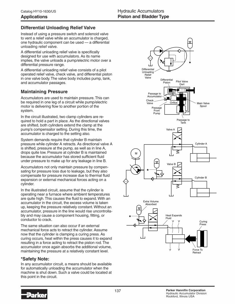
137 Parker Hannifin CorporationHydraulic Accumulator DivisionRockford, Illinois USA
Hydraulic AccumulatorsPiston and Bladder Type
Catalog HY10-1630/US
Differential Unloading Relief ValveInstead of using a pressure switch and solenoid valveto vent a relief valve while an accumulator is charged,one hydraulic component can be used — a differentialunloading relief valve.A differential unloading relief valve is specificallydesigned for use with accumulators. As its nameimplies, the valve unloads a pump/electric motor over adifferential pressure range.A differential unloading relief valve consists of a pilotoperated relief valve, check valve, and differential pistonin one valve body. The valve body includes pump, tank,and accumulator passages.
Maintaining PressureAccumulators are used to maintain pressure. This canbe required in one leg of a circuit while pump/electricmotor is delivering flow to another portion of thesystem.
In the circuit illustrated, two clamp cylinders are re-quired to hold a part in place. As the directional valvesare shifted, both cylinders extend the clamp at thepump’s compensator setting. During this time, theaccumulator is charged to the setting also.
System demands require that cylinder B maintainpressure while cylinder A retracts. As directional valve Ais shifted, pressure at the pump, as well as in line A,drops quite low. Pressure at cylinder B is maintainedbecause the accumulator has stored sufficient fluidunder pressure to make up for any leakage in line B.
Accumulators not only maintain pressure by compen-sating for pressure loss due to leakage, but they alsocompensate for pressure increase due to thermal fluidexpansion or external mechanical forces acting on acylinder.
In the illustrated circuit, assume that the cylinder isoperating near a furnace where ambient temperaturesare quite high. This causes the fluid to expand. With anaccumulator in the circuit, the excess volume is takenup, keeping the pressure relatively constant. Without anaccumulator, pressure in the line would rise uncontrolla-bly and may cause a component housing, fitting, orconductor to crack.
The same situation can also occur if an externalmechanical force acts to retract the cylinder. Assumenow that the cylinder is clamping a curing press. Ascuring occurs, heat within the press causes it to expandresulting in a force acting to retract the piston rod. Theaccumulator once again absorbs the additional volume,maintaining the pressure at a relatively constant level.
*Safety Note:In any accumulator circuit, a means should be availablefor automatically unloading the accumulator when themachine is shut down. Such a valve could be located atthis point in the circuit.
*
Extra VolumeAbsorbed
Heat ExpandsFluid
˚F
˚F˚F
Force ToRetract
CuringPress
*
*
Valve A
Valve B
Cylinder A
Cylinder B
M
Passage toTank
Pilot ValveDart
DifferentialPiston
Passage toAccumulator
CheckValve
PassageFromPump
Orifice Main ValveSpool
DifferentialUnloading
ReliefValve
˚F
Applications

138 Parker Hannifin CorporationHydraulic Accumulator DivisionRockford, Illinois USA
Hydraulic AccumulatorsPiston and Bladder Type
Catalog HY10-1630/US
Developing FlowSince charged accumulators are a source of hydraulicpotential energy, stored energy of an accumulator canbe used to develop system flow when system demandis greater than pump delivery. For instance, if amachine is designed to cycle infrequently, a smalldisplacement pump can be used to fill an accumulatorover a period of time. When the moment arrives for themachine to operate, a directional valve is shifteddownstream, and the accumulator delivers the requiredpressurized flow to an actuator.
Using an accumulator in combination with a smallpump in this manner conserves peak horsepower. Forinstead of using a large pump/electric motor togenerate a large horsepower all at once, the work canbe evenly spread over a time period with a small pump/electric motor.
Absorbing ShockHydro-pneumatic accumulators are sometimes used toabsorb system shock even though in this applicationthey are difficult to properly design into a system.
Shock in a hydraulic system may be developed fromthe inertia of a load attached to a cylinder or motor. Or,it may be caused by fluid inertia when system flow issuddenly blocked or changed direction as a directionalvalve is shifted quickly. An accumulator in the circuit willabsorb some of the shock and not allow it to be trans-mitted fully throughout the system.
Shock may also occur in a hydraulic system due toexternal mechanical forces. In the circuit illustrated, theload attached to the cylinder has a tendency to bouncecausing the rod to be pushed in and shock generated.An accumulator positioned in the cylinder line can helpreduce the shock effects.
*Safety Note:
In any accumulator circuit, a means should be availablefor automatically unloading the accumulator when themachine is shut down. Such a valve could be located atthis point in the circuit.
M
Restriction ControlsAccumulator Discharge
*
*
Developing System Flow
M
*
Load Bounces
100GPM
Applications

139 Parker Hannifin CorporationHydraulic Accumulator DivisionRockford, Illinois USA
Hydraulic AccumulatorsPiston and Bladder Type
Catalog HY10-1630/US
Please fill out and fax to 815-636-4113.For assistance, call 815-636-4100.
CUSTOMER:
ADDRESS:
CONTACT:
PHONE:
FAX:
EMAIL:
Quantity/Release: ___________________________
Quantity (Annual): ___________________________
Type (Piston or Bladder): _____________________
Bore Size (piston only): ______________________
Capacity: __________________________________
Working Pressure/Design Factor. _______________
Seal Type/Compound:________________________
Hydraulic Port:______________________________
Gas Port:__________________________________
Operating Temperature Range:_________________
System Fluid: ______________________________
Gas Valve:_________________________________
Precharge:_________________________________
Water Service? ____________________________
Plating/Coating: ____________________________
Material Type: ______________________________
Paint: ____________________________________
Switches: _________________________________
Certification: _______________________________
Special Test?_______________________________
Special Label? _____________________________
Customer Drawing Included? _________________
Customer Part # ___________________________
Envelope Restrictions: _______________________
Contact Information
Application Description/Comments
Customer Requirements
FORM-0117, Rev. 1
Application Data Sheet

140 Parker Hannifin CorporationHydraulic Accumulator DivisionRockford, Illinois USA
Hydraulic AccumulatorsPiston and Bladder Type
Catalog HY10-1630/US
Notes

121 Parker Hannifin CorporationHydraulic Accumulator DivisionRockford, Illinois USA
SurgeKushons• General Oil Service• Water & Chemical Service• Slurry Service• Fire Protection Service
Greer SurgeKushons Feature:• Operating Pressures to 500 PSI
• Eight Different Capacities – from 2 1/2 to 120 gallons
• The Highest Quality In-House Manufactured Bladders
• ASME Certification Standard – FM and UL Approved Available
• Chemical and Water Service Optional
• Four Bladder Compounds to Suit a Variety of Fluids and Temperatures
BLADDER PRODUCTS

Catalog HY10-1630/US SurgeKushons
122 Parker Hannifin CorporationHydraulic Accumulator DivisionRockford, Illinois USA
In high volume fluid handling systems, shocks are experiencedwhen valves open or close or when pumps are started or shutdown. SurgeKushons are essentially low pressure bladderaccumulators designed to take these shocks out of high flow fluidhandling systems. Applications for SurgeKushons include watersprinkling systems, water handling systems, refueling systems,and chemical and process plants.
Photo 19
Fuel loading absorbsshock from pump startupand stopping
Protecting sensitive metersand small diameter pipingfrom valve closure on fuelingtrucks
Protection from large valveclosure shocks
Applications Introduction

Catalog HY10-1630/US SurgeKushons
123 Parker Hannifin CorporationHydraulic Accumulator DivisionRockford, Illinois USA
Refineries — Shock frompump starting and stopping
Liquid bulk handlingabsorbs surges and shocksfrom fluids in motion
Aircraft protection fromvalve closure shocks.
Applications Introduction

Catalog HY10-1630/US SurgeKushons
124 Parker Hannifin CorporationHydraulic Accumulator DivisionRockford, Illinois USA
When a valve in a high volume fluid handling system opens orcloses or a pump starts or starts, there can be pressure spikesgenerated that are four times greater than the system’s designpressure. This shock can burst pipes, shatter or loosen fittings,disable pumps and knock out instrumentation. Greer’sSurgeKushons are accumulators designed to protect fluidhandling systems from surge and water hammer damage byabsorbing the kinetic energy before it can cause seriousdamage.
Underground or overhead water or fluid systems can be madesafer and more trouble-free with the proper SurgeKushonapplications. Fire protection systems using sprinklers shouldbe secured with SurgeKushons. Airport refueling facilities,petro-chemical plants, bulk handling systems, and refineriescannot afford surge-ruptured lines and the accompanyingspills.
SurgeKushon Protection Pays...• control surges and water hammer• help save lives and property
• get immediate pay-back from reduced maintenance anddamage
• save pump energy by continually holding pressure
• get longer life from equipment• overall... the whole system works better
Greer SurgeKushons…Your #1 Choice for Surge Protection!Greer SurgeKushons are made by the leading manufacturer ofbladder accumulators in North America. The broadSurgeKushon offering includes:
• 275 & 500 PSI Rated General Service
• 275 & 500 PSI Rated Slurry Service• 275 & 400 PSI Rated FM Approved Fire Service• Water & Chemical Service Option
• Stainless Steel Construction Available - Consult Factory
Virtually all of the components used in the construction of theSurgeKushons including the shells and the bladders them-selves, the heart of any SurgeKushon, are manufactured in-house. All processes are internally controlled to the higheststandards of quality and consistency.
Also, we offer application assistance and will help to designthe proper SurgeKushon arrangement to fit your systemsrequirements including sizing and placement.
SpecificationsMaterials• Shell – carbon steel to ASME material specifications• Screens – stainless steel• Flanges – carbon steel forgings to ASME material
specification• Gas Valve Protector – steel• Gas Valve Stem – steel• Bladders – various polymers, see Standard and Optional
Bladders in this section.
Maximum Flow Rates
Flange Max. Recommended Flow* Size GPM LPM
3” 350 1325
3” Slurry 400 1514
4” & 6” 1000 3785
8” & 10” 1400 5300
*Note: with fliud viscosity of 60-70 SSU
Pressure Ratings – SurgeKushons are available in a varietyof maximum operating pressures up to 500 PSI- all at mini-mum 4 to 1 design factors. See “Models, Capacities andDimensions” pages for rated pressures.
Fluids – SurgeKushons are compatible with a wide variety offluids. The standard accumulator may be used with petroleum-based industrial or water-based flame resistant fluids. Bladderscompatible with most industrial fluids can be furnished onspecial orders with temperature ranges from-60°F to 400°F (-53°C to 204°C).
Precharge – Units are shipped with a 25 psi nitrogenprecharge as standard. For other precharge pressures, specifyat the time of order.
Available Options – options available on SurgeKushonsinclude:
• Bladder Compounds (see Standard and Optional Bladders inthis section)
• Water & Chemical Service (see Water & Chemical ServiceOption in this section)
Certifications – ASME (Section VIII, Div. 1) is available asstandard on SurgeKushons with FM Approved and UL Listedas available options.
Specifications Introduction

Catalog HY10-1630/US SurgeKushons
125 Parker Hannifin CorporationHydraulic Accumulator DivisionRockford, Illinois USA
1 ShellSurgeKushon shells are fabricated from carbon steel withminimum 4 to 1 design factors at normal operating pressures.SurgeKushon shells meet ASME material specifications asstandard.
2 BladderThe heart and soul of a SurgeKushon, bladders are manufac-tured in-house to control the material blending, molding, andcritical seam assembly and curing processes. It is widelyaccepted that Greer bladders are the highest quality bladdersin the industry. Bladders are offered in four different standardcompounds to suit a variety of fluids and operating tempera-tures. Special compounds are available for unusual or severeapplications.
3 Bladder StemsAll SurgeKushons are fitted as standard with two-piecebladder stems with replaceable gas valve cartridge for ease ofserviceability. Also, the two-piece stem will accept highpressure military gas valves and permanent mount gaugeadapters.
4 Port FlangesANSI RF flanges, 150 and 300 lb., are supplied as standard.Sizes range from 3” thru 10” with special sizes available(consult factory).
5 ScreensSurgeKushons are equipped as standard with stainless steelscreens to prevent bladder extrusion and for corrosionresistance.
6 Top Repairable25 gallon and larger units are supplied as top repairable. Thetop repairable design permits easy checking and maintenanceof the bladder without removing the accumulator from theservice line, saving time and money.
7 Gas ValveAll accumulators are fitted with a gas valve for ease of gasprecharging. 2 1/2 thru 10 gallon units are equipped with acored gas valve cartridge (ISO-4570-8VI) for ease of mainte-nance. 25 gallon and larger units are equipped with apoppet-type (military) gas valve cartridge (Mil. Spec MS28889-2). For safety, the gas valve vents if unscrewed.
7
6 3
54
2
1
Design Features & Benefits Introduction

Catalog HY10-1630/US SurgeKushons
126 Parker Hannifin CorporationHydraulic Accumulator DivisionRockford, Illinois USA
SurgeKushon A BNominal Bladder Part Repair Pressure Inch RF Weight
Size Code Number Kit Rating (mm) Flange-01 Slurry SK02S3FA01A1 703184
2-1/2 gallon -01 SK02A3FA01A1 702634 275 PSI 19.25 8.60 3”, 150# 63
(9.5 liters) -04 SK02A3FA04A1 704330 (19 Bar) (489) (218) (29)
-08 SK02A3FA08A1 702636
-28 SK02A3FA28A1 702635
-01 Slurry SK05S3FA01A1 703191
5 gallon -01 SK05A3FA01A1 702637 275 PSI 29.50 8.60 3”, 150# 89
(19 liters) -04 SK05A3FA04A1 704331 (19 Bar) (749) (218) (40)
-08 SK05A3FA08A1 702639
-28 SK05A3FA28A1 702638
-01 Slurry SK10S3FB01A1 703198
10 gallon -01 SK10A3FA01A1 702640 275 PSI 50.63 8.60 3”, 150# 137
(38 liters) -04 SK10A3FA04A1 704332 (19 Bar) (1286) (218) (Slurry, (62)
-08 SK10A3FA08A1 702642 4”, 150#)
-28 SK10A3FA28A1 702641
-01 SK25A5PB01A1 702615
25 gallons -04 SK25A5PB04A1 704333 500 PSI 35.69 22.00 4”, 300# 320
(95 liters) -08 SK25A5PB08A1 702617 (34 Bar) (907) (559) (145)
-28 SK25A5PB28A1 702616
-01 SK40A5PB01A1 702621
40 gallons -04 SK40A5PB04A1 704334 500 PSI 43.44 22.00 4”, 300# 368
(151 liters) -08 SK40A5PB08A1 702623 (34 Bar) (1103) (559) (167)
-28 SK40A5PB28A1 702622
-01 SK80A5PB01A1 702626
80 gallons -04 SK80A5PB04A1 704335 500 PSI 64.44 22.00 4”, 300# 660
(303 liters) -08 SK80A5PB08A1 702627 (34 Bar) (1637) (559) (300)
-28 SK80A5PB28A1
-01 SK100A5PB01A1 702630
100 gallons -04 SK100A5PB04A1 704336 500 PSI 84.44 22.00 4”, 300# 885
(379 liters) -08 SK100A5PB08A1 702631 (34 Bar) (2145) (559) (402)
-28 SK100A5PB28A1
-01 SK120A5PB01A1 702643
120 gallons -04 SK120A5PB04A1 704337 500 PSI 101.38 22.00 4”, 300# 1010
(454 liters) -08 SK120A5PB08A1 702644 (34 Bar) (2575) (559) (459)
-28 SK120A5PB28A1
General and Slurry Service Models, Capacities and Dimensions
ASME Certified General Service SurgeKushons
1) Note: Bladder Codes: -01 = Buna-Nitrile, -04 = Hydrin, -08 = EPR, & -28 = Fluorocarbon)
A
B

Catalog HY10-1630/US SurgeKushons
127 Parker Hannifin CorporationHydraulic Accumulator DivisionRockford, Illinois USA
ANSI 275 PSI Rated with 150# Flange 400 PSI Rated with 300# Flange Nominal B RF Model A WeightModel A Weight Size Inch Flange Number Number
mm Size Inch (mm) lbs. (Kg.) Inch (mm) lbs. (Kg.)2-1/2 gallon(9.5 liters) 8.60 3” SK02W3FA01A1 16.94 (430) 63 (29)RK #702634 (218)5 Gallon(19 liters) 8.60 3” SK05W3FA01A1 28.94 (735) 89 (40)RK #702637 (218)10 Gallon(38 liters) 8.60 3” SK10W3FA01A1 50.63 (1286) 137 (62)RK #702640 (218)
4” SK25W3FB01A1 35.56 (903) 310 (141)25 gallon 22.00 4” SK25W3FB01A1 35.69 (907) 310 (141) SK25W4PB01A1 35.69 (907) 320 (145)(95 liters) (559) 6” SK25W3FC01A1 37.50 (953) 319 (145) SK25W4PC01A1 38.00 (965) 338 (154)RK #702615 8” SK25W3FD01A1 37.56 (954) 335 (152) SK25W4PD01A1 37.94 (964) 362 (165)
10” SK25W3FE01A1 41.56 (1056) 347 (158)4” SK40W3FB01A1 43.31 (1100) 358 (163)
40 gallons 22.00 4” SK40W3FB01A1 43.44 (1103) 358 (163) SK40W4PB01A1 43.44 (1103) 368 (167)(151 liters) (559) 6” SK40W3FC01A1 45.25 (1149) 367 (167) SK40W4PC01A1 45.75 (1162) 386 (175)RK #702621 8” SK40W3FD01A1 45.31 (1151) 383 (174) SK40W4PD01A1 45.69 (1161) 410 (186)
10” SK40W3FE01A1 49.31 (1252) 395 (180)4” SK80W3FB01A1 64.25 (1632) 650 (295)
80 Gallon 22.00 4” SK80W3FB01A1 64.44 (1637) 650 (295) SK80W4PB01A1 64.44 (1637) 660 (300)(303 liters) (559) 6” SK80W3FC01A1 66.25 (1683) 659 (300) SK80W4PC01A1 66.75 (1695) 678 (308)RK #702626 8” SK80W3FD01A1 66.31 (1684) 675 (307) SK80W4PD01A1 66.69 (1694) 702 (319)
10” SK80W3FE01A1 70.31 (1786) 687 (312)4” SK100W3FB01A1 84.81 (2154) 875 (398)
100 Gallon 22.00 4” SK100W3FB01A1 84.88 (2156) 875 (398) SK100W4PB01A1 84.44 (2145) 885 (402)(379 liters) (559) 6” SK100W3FC01A1 86.69 (2202) 884 (402) SK100W4PC01A1 87.19 (2215) 903 (410)RK #702630 8” SK100W3FD01A1 86.75 (2203) 900 (409) SK100W4PD01A1 87.13 (2213) 927 (421)
10” SK100W3FE01A1 90.75 (2305) 912 (415)4” SK120W3FB01A1 101.31 (2573) 1000 (455)
120 Gallons 22.00 4” SK120W3FB01A1 101.38 (2575) 1000 (455) SK120W4PB01A1 101.38 (2575) 1010 (459)(454 liters) (559) 6” SK120W3FC01A1 103.19 (2621) 1009 (459) SK120W4PC01A1 103.69 (2634) 1028 (467)RK #702643 8” SK120W3FD01A1 103.25 (2623) 1025 (466) SK120W4PD01A1 103.63 (2632) 1052 (478)
10” SK120W3FE01A1 107.25 (2724) 1037 (471)
Water/Chemical Service SurgeKushons (All Bladders are Code -1 Nitrile)
Water/Chemical Service Models, Capacities and Dimensions
1) Note: RK = Repair Kit
A
B

Catalog HY10-1630/US SurgeKushons
128 Parker Hannifin CorporationHydraulic Accumulator DivisionRockford, Illinois USA
Options & Ordering Information
Standard and Optional BladdersA variety of bladders are offered to suit a wide range of fluidsand operating temperatures. The following table lists theoptional bladders available, their recommended operating
Recommended MaximumCode Polymer Operating* Temperature with General Application
Temperature Range Reduced Life & Compatibility1
01 Buna-Nitrile -20°F to 165°F 225°F Greer's Standard Compound – Compatible with-10°C to 80°C 93°C most mineral oil based fluids.
04 Hydrin -40°F to 160°F 200°F Compatible with most mineral oil based fluids(Lo-Temp) -40°C to 71°C 93°C with enhanced low temperature performance.
08 Ethylene -40°F to 200°F 300°F Compatible with some synthetic fluids and water.Propylene -40°C to 93°C 149°C
28 Flurocarbon -10°F to 250°F 400°F Compatible with most mineral oil based fluids atElastomer -23°C to 121°C 204°C higher temperatures and some exotic fluids.
1) Note: Consult your local Greer distributor or the factory for fluid compatibility information. Temperature ranges may vary depending uponthe fluid used in the hydraulic system.* The temperatures listed indicate the operating temperature range of the seals, not the SurgeKushon. For the Minimum Design MetalTemperature (MDMT) of ASME certified SurgeKushons, please consult the factory.
SK 10 A 3 FA 01 A 1A Std. Oil Service
W Water & Chemical Service
S Slurry Service1
1) Note: Includes water service.
SK SeriesSurgeKushons
Code Size
02 2½ gal. (9 1/2 liters)05 5 gal. (19 liters)10 10 gal. (38 liters)25 25gal. (95 liters)40 40 gal. (151 liters)80 80 gal. (303 liters)100 100 gal. (379 liters)120 120 gal. (454 liters)
Rated Pressure2 200 PSI (14 Bar)
3 275 PSI (19.0 Bar)
4 400 PSI (28 Bar)
5 500 PSI (35 Bar)
01 Buna-Nitrile
04 Hydrin
08 EPR
28 Fluorocarbon
A Standard ASME Cert.
S Special
1 Standard
* Special DesignNo. Assigned
temperature ranges, and the types of fluids that are generallycompatible.
Bladder KitsA full range of genuine Greer replacement bladder kits areavailable to bring your SurgeKushon back to original conditionshould replacement become necessary. All bladder kitsinclude port o-ring and back-up seals and gas valves withsecondary seals. (Consult factory for SurgeKushon repair kitnumbers).
Water & Chemical Service OptionStandard SurgeKushons are manufactured from carbon steeland are intended for oil or non-corrosive fluid service. Forwater or corrosive fluid service, the Water & Chemical Serviceoption should be specified. With this corrosive resistant option,all parts that come into contact with the system fluid are madefrom stainless steel or have a Skotchkote 134® coating.
How to Order SurgeKushonsSurgeKushons can be specified by using the symbols in the chart below to develop a model number. Select only those symbolsthat represent the features desired, and place them in the sequence indicated by the example at the top of the chart.
Port FlangesFA 3”, 150#ANSI RF Flg. PA 3”, 300#ANSI RF Flg.
FB 4”, 150#ANSI RF Flg. PB 4”, 300#ANSI RF Flg.
FC 6”, 150#ANSI RF Flg. PC 6”, 300#ANSI RF Flg.
FD 8”, 150#ANSI RF Flg. PD 8”, 300#ANSI RF Flg.
FE 10”, 150#ANSI RF Flg. XX Special
Series Size Construction Pressure Port Material Variation CodeRated Bladder Design Design

87 Parker Hannifin CorporationHydraulic Accumulator DivisionRockford, Illinois USA
Inline Pulse-Tone™Hydraulic Shock Suppressors
Inline Pulse-Tone™Shock Suppressors Feature:• Three Bladder Polymers for a Wide
Range of Fluids and Temperatures• NPT, BSPP, SAE or Split Flange
Connections• Mounting in Any Position• 3000 PSI Models for Water/Chemical
Service
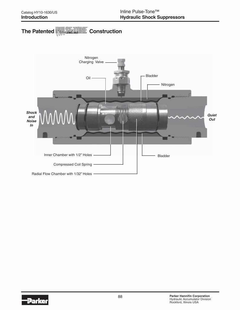
Catalog HY10-1630/US
PageInline Pulse-Tone™Hydraulic Shock Suppressors
88 Parker Hannifin CorporationHydraulic Accumulator DivisionRockford, Illinois USA
The Patented Construction
Shockand
NoiseIn
QuietOut
NitrogenCharging Valve
Bladder
Inner Chamber with 1/2” Holes
Compressed Coil Spring
Radial Flow Chamber with 1/32” Holes
Bladder
Nitrogen
Oil
Introduction

Catalog HY10-1630/US
Page
89 Parker Hannifin CorporationHydraulic Accumulator DivisionRockford, Illinois USA
Inline Pulse-Tone™Hydraulic Shock Suppressors
An Inline Pulse-Tone suppressor is located as close tothe pump as possible, usually directly at the pumpoutlet, to stop pulsations and noise before they travelthrough the piping and radiate off other structuralcomponents.
Noise pollution is the hottest topic in the hydraulicindustry today. Lab tests show that pump noise levelsare increased by 2-3 dB(A) just by adding 12 feet ofoutlet and return lines. The lines do not generatenoise. They radiate noise when they respond topulsations or vibrations. The pulsations are usuallygenerated by the pump, and the vibrations are radi-ated by large flat machine surfaces.
Not only do hydraulic lines radiate noise, but theyfrequently provide the primary path for propagatingnoise from the pump to components that, in turn,react to the noise and radiate additional sound. Thishelps explain why many pump manufacturers have avery low dB(A) pump rating, but when the pump isinstalled on a power unit, the sound rating is muchhigher.
Introduction
It is almost impossible to forecast how much addi-tional sound the hydraulic lines and surroundingstructure will radiate. This is why many power unitsare enclosed after they have been manufactured andinstalled.
The Inline Pulse-Tone reduces pump pulsations andshock. When you stop pulsation and vibration, youstop the cause of component wear and leakage. Apower unit with an Inline Pulse-Tone installed canoperate at higher RPM with smaller, less expensivecomponents . . . and less noise.
NOTE OF INTEREST: An increase of 2.71 dBdoubles the intensity noise level.
Why Should You Use the Shock Suppressor?
How Does the Work?
As shown in the diagram on the facing page, oilflowing into the Pulse-Tone goes through threedifferent baffles or diffusers. These metal bafflesare designed to convert 1/2” diameter holes to 1/32”diameter holes. The total radial distance throughthese baffles is only 1/4”.
After passing through these holes, pulsations strike anitrogen charged rubber bladder. The bladder deflectseach time it is hit by a pulsation. This slight deflectionof the bladder reduces the shock and noise.
The bladder is usually charged with nitrogen to 50%to 60% of the hydraulic operating pressure. The 1/32”diameter holes in the last baffle are so small that thebladder cannot extrude into them.
The large area of the bladder, its ability to oscillate ata high frequency and the short distance each pulsa-tion has to travel once it enters the unit explain theeffectiveness of the Pulse-Tone.
Selecting a is Easy!
No complex sizing forumla is required. The InlinePulse-Tone hydraulic shock suppressor is sized tomatch your hydraulic line size. There is a unit to fit
every pipe and tube size from 3/8” to 2” with threadedor flanged connections. Models are available for both3000 PSI and 5000 PSI hydraulic system pressures.
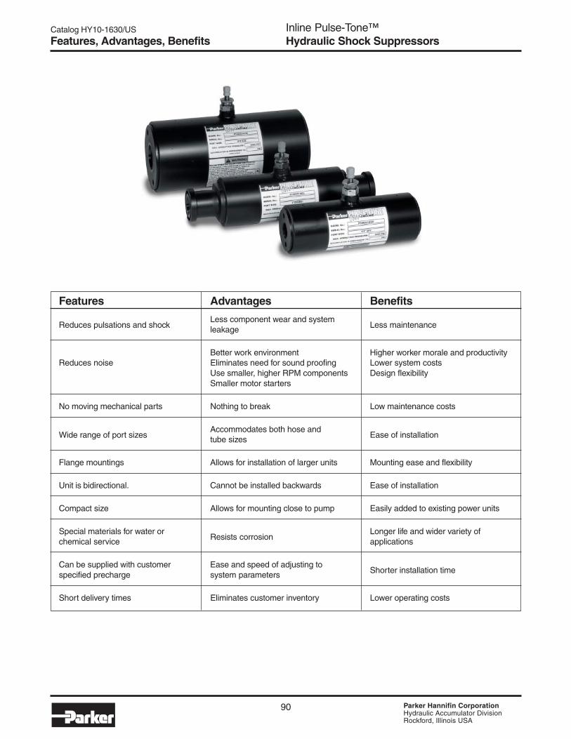
Catalog HY10-1630/US
PageInline Pulse-Tone™Hydraulic Shock Suppressors
90 Parker Hannifin CorporationHydraulic Accumulator DivisionRockford, Illinois USA
Features, Advantages, Benefits
Features Advantages Benefits
Reduces pulsations and shockLess component wear and system
Less maintenanceleakage
Better work environment Higher worker morale and productivityReduces noise Eliminates need for sound proofing Lower system costs
Use smaller, higher RPM components Design flexibilitySmaller motor starters
No moving mechanical parts Nothing to break Low maintenance costs
Wide range of port sizesAccommodates both hose and
Ease of installationtube sizes
Flange mountings Allows for installation of larger units Mounting ease and flexibility
Unit is bidirectional. Cannot be installed backwards Ease of installation
Compact size Allows for mounting close to pump Easily added to existing power units
Special materials for water orResists corrosion
Longer life and wider variety ofchemical service applications
Can be supplied with customer Ease and speed of adjusting toShorter installation timespecified precharge system parameters
Short delivery times Eliminates customer inventory Lower operating costs

Catalog HY10-1630/US
Page
91 Parker Hannifin CorporationHydraulic Accumulator DivisionRockford, Illinois USA
Inline Pulse-Tone™Hydraulic Shock Suppressors
Models• 3000 psi rated for oil applications
• 3000 psi Stainless Steel for water andchemical applications
• 5000 psi for high pressure oil applications
Port ConnectionsFour types of hydraulic line connections areavailable:
• NPT pipe connections from 3/8” to 2” pipe
• BSPP connections from 3/8” to 2” pipe
• SAE port connection from 3/8” to 2” tubing
• Split flange connection from 3/4” to 3”
Inline Pulse-Tone units can be ordered with anycombination of ends, such as a split flange one endand a straight thread on the opposite end. Whenordering, specify the type of connection for eachend.
Bladder Materials• Standard material is high temperature HNBR,
-50° to 300°F (-45° to 149°C)
• Fluorocarbon or EPR bladders are available forspecial applications
PrechargeThe unit can be shipped with a nitrogen prechargeequal to 50% of hydraulic system pressure. Checkprecharge every three months to maintain maximumefficiency. (See page 184 for procedures.)
MountingThe Pulse-Tone may be mounted in any position,horizontal or vertical. Since there are no movingparts, either end may be used for inlet or outlet.Split flange mounting makes it possible to break anexisting connection to add the Pulse-Tone betweenthe flanges.
General Information
235 psi
25 psi
40 psi
420 psi
5.55 MSEC, 180 HZ
75 psi
12 psi
Examples of Pulsation ReductionThe examples below show pulsations forpumps at various pressures before and afterinstallation of the Inline Pulse-Tone.
Piston Pump at 4000 psi and 1800 rpm
Piston Pump at 2000 psi and 1800 rpm
Piston Pump at 750 psi and 1200 rpm
Before
After
Before
After
Before
After

Catalog HY10-1630/US
PageInline Pulse-Tone™Hydraulic Shock Suppressors
92 Parker Hannifin CorporationHydraulic Accumulator DivisionRockford, Illinois USA
3000 PSI with Threaded Connections
3000 PSI Pipe Thread ConnectionsFlow, Flow,
NPT BSPP GPM GPMDimensions, inch (mm) Weight
Model Size Size 15’/sec 20’/sec* D H L lbs. (kg)
PT250D1H3/8 3/8 11.3 15.1 2.5 1.75 6.875 6.51/2 1/2 (63.5) (44.5) (174.6) (3)
3/4 3/42.625 1.75 8.13 8.0PT262D1H 1 1 24.2 32.1(66.7) (44.5) (206.5) (3.6)— 1¼
1 1PT400D1H 1¼ 1¼ 68.9 91.9
4.0 1.75 8.875 24.5
1½ 1½(101.6) (44.5) (225.4) (11.1)
PT475D1H1½ 1½ 128.0 171.0 4.75 1.75 10.5 312 2 (120.7) (44.5) (266.7) (14.1)
3000 PSI Straight Thread ConnectionsFlow, Flow,
Tube GPM GPMDimensions, inch (mm) Weight
Model Size Thread 15’/sec 20’/sec* D H L lbs. (kg)
.375 9/16–18PT250D1H .500 3/4–16 11.3 15.1
2.5 1.75 6.875 6.5
.625 7/8–14(63.5) (44.5) (174.6) (3)
.750 1-1/16–12PT262D1H 1.00 1-5/16–12 24.1 32.1
2.625 1.75 8.13 8
1.25 1-5/8–12(66.7) (44.5) (206.5) (3.6)
1.00 1-5/16–12PT400D1H 1.25 1-5/8–12 68.9 91.9
4.0 1.75 8.875 24.5
1.50 1-7/8–12(101.6) (44.5) (225.4) (11.1)
PT475D1H 2.00 2-1/2–12 128.0 171.04.75 1.75 10.5 31
(120.7) (44.5) (266.7) (14.1)
L
H
D
ThreadSize
* Pressure drop in the suppressor is equal to pressure drop in 8” of tubing. Flow rates can be at least 50% higherthan those listed for 20’/sec. without excessive pressure drop.

Catalog HY10-1630/US
Page
93 Parker Hannifin CorporationHydraulic Accumulator DivisionRockford, Illinois USA
Inline Pulse-Tone™Hydraulic Shock Suppressors
3000 PSI Pipe Thread ConnectionsFlow, Flow,
NPT GPM GPMDimensions, inch (mm)
WeightModel Size 15’/sec 20’/sec* D H L lbs. (kg)
3/4”24.2 32.1
2.625 1.75 8.13 8.0PT262D3H
1” (66.7) (44.5) (206.5) (3.6)
1”PT400D3H 1¼” 68.9 91.9
4.0 1.75 8.875 24.5
1½”(101.6) (44.5) (225.4) (11.1)
3000 PSI Straight Thread ConnectionsFlow, Flow,
Tube GPM GPMDimensions, inch (mm)
WeightModel Size Thread 15’/sec 20’/sec* D H L lbs. (kg)
.750 1-1/16–12PT262D3H 1.00 1-5/16–12 24.1 32.1
2.625 1.75 8.13 8
1.25 1-5/8–12(66.7) (44.5) (206.5) (3.6)
1.00 1-5/16–12PT400D3H 1.25 1-5/8–12 68.9 91.9
4.0 1.75 8.875 24.5
1.50 1-7/8–12(101.6) (44.5) (225.4) (11.1)
L
H
D
ThreadSize
* Pressure drop in the suppressor is equal to pressure drop in 8” of tubing. Flow rates can be at least 50% higherthan those listed for 20’/sec. without excessive pressure drop.
3000 PSI Water/Chemical Service
Cutaway
Three “304” StainlessSteel Chambers
Tube Nickel PlatedInside and Out
“304” Stainless End Pieces

Catalog HY10-1630/US
PageInline Pulse-Tone™Hydraulic Shock Suppressors
94 Parker Hannifin CorporationHydraulic Accumulator DivisionRockford, Illinois USA
3000 PSI for Code 61 Flange Mounting
Model Flange Code 61 Flange Code 62 Flange*
Size D A B L E F A B L E F
0.752.625 1.75 .56 10.12 1.875 0.875 2.000 .75 10.620 2.000 0.938(66.7) (44.5) (14.2) (257.0) (47.6) (22.2) (50.8) (19.1) (269.7) (50.8) (23.8)
PT262D1HP 1.002.625 1.75 .62 10.12 2.062 1.030 2.000 .94 10.620 2.250 1.094(66.7) (44.5) (15.7) (257.0) (52.4) (26.2) (50.8) (23.9) (269.7) (57.1) (27.8)
1.252.625 2.00 .56 10.62 2.312 1.188 2.250 1.06 11.120 2.625 1.250(66.7) (50.8) (14.2) (269.7) (58.7) (30.2) (57.1) (26.9) (282.4) (66.7) (31.8)
1.254.00 2.25 .56 13.12 2.312 1.188 2.250 1.06 13.125 2.625 1.250
(101.6) (57.1) (14.2) (333.2) (58.7) (30.2) (57.1) (26.9) (333.4) (66.7) (31.8)
PT400D1HP 1.504.00 2.25 .62 13.12 2.750 1.406 2.250 1.19 13.625 3.125 1.438
(101.6) (57.1) (15.7) (333.2) (69.9) (35.7) (57.1) (30.2) (346.1) (79.4) (36.5)
2.004.00 2.38 .62 13.38 3.062 1.688 2.620 1.44 13.875 3.812 1.750
(101.6) (60.4) (15.7) (339.9) (77.8) (42.9) (66.5) (36.6) (352.4) (96.8) (44.5)
2.004.75 2.38 .62 15.00 3.062 1.688 2.620 1.44 13.875 3.812 1.750
(120.6) (60.4) (15.7) (381.0) (77.8) (42.9) (66.5) (36.6) (352.4) (96.8) (44.5)
PT475D1HP 2.50**4.75 2.875 .75 16.00 3.500 2.000
— — — — —(120.6) (73.0) (19.0) (406.4) (88.9) (50.8)
3.00***4.75 3.25 .88 16.75 4.188 2.438
— — — — —(120.6) (82.6) (22.3) (425.4) (106.4) (61.9)
* When using Code 62 flanges, do not exceed 3000 psi pressure rating of the unit.** Maximum pressure rating for this flange is 2500 psi.*** Maximum pressure rating for this flange is 2000 psi.
3000 PSI Flange Mounted
D
FlangeSize
1.75 (44.5)
L
Ordering NoteThe Pulse-Tone flange mounted unit is not supplied with split flanges.
A
L
B
E
F

Catalog HY10-1630/US
Page
95 Parker Hannifin CorporationHydraulic Accumulator DivisionRockford, Illinois USA
Inline Pulse-Tone™Hydraulic Shock Suppressors5000 PSI Flange Mounted
5000 PSI for Flange Mounting
Model Flange Code 62 Flange* Dimensions, inch (mm)
Number Size A B D L E F
1.002.000 .94 3.38 10.620 2.250 1.094
PT338C1HP(50.8) (23.9) (85.8) (269.7) (57.2) (27.8)
1.252.250 1.06 3.38 11.120 2.625 1.250(57.2) (26.9) (85.8) (282.4) (66.7) (31.8)
1.252.250 1.06 5.00 13.125 2.625 1.250(57.2) (26.9) (127.0) (333.4) (66.7) (31.8)
PT500C1HP 1.502.500 1.19 5.00 13.625 3.125 1.438(63.5) (30.2) (127.0) (346.1) (79.4) (36.5)
2.002.620 1.44 5.00 13.875 3.812 1.750(66.5) (35.6) (127.0) (352.4) (96.8) (44.5)
FlangeSize
D
L
1.28 (32.5)
Ordering NoteThe Pulse-Tone flange mounted unit is not supplied with split flanges.
A
L
B
E
F

Catalog HY10-1630/US
PageInline Pulse-Tone™Hydraulic Shock Suppressors
96 Parker Hannifin CorporationHydraulic Accumulator DivisionRockford, Illinois USA
5000 PSI Threaded Connection
5000 PSI Straight Thread ConnectionsFor Thread
Tube In Maximum Dimensions, inch (mm)
WeightModel Suppressor Rate Flow D H L lbs. (kg)
.750 1-1/16–12PT338C1H 1.00 1-5/16–12 49 GPM
3.38 1.28 8.13 15
1.25 1-5/8–12(85.8) (32.5) (206.5) (6.36)
1.00 1-5/16–12PT500C1H 1.25 1-5/8–12 150 GPM
5.0 1.28 8.88 48
1.50 1-7/8–12(127.0) (32.5) (225.6) (21.8)
* Pressure drop in unit is equal to pressure drop of 8” of tubing. Flow rates can be at least 50% higher than those listed for 20’/sec withoutexcessive pressure drop.
D
H
L
ThreadSize
Repair KitsRepair kits include a bladder and o-rings. Order by series and seal material.
Series HNBR EPR Fluorocarbon
250 RKPT2500H0 RKPT2500D0 RKPT2500E0
262 & 338 RKPT2620H0 RKPT2620D0 RKPT2620E0
400 & 500 RKPT4000H0 RKPT4000D0 RKPT4000E0
475 RKPT4750H0 RKPT4750D0 RKPT4750E0

Catalog HY10-1630/US
Page
97 Parker Hannifin CorporationHydraulic Accumulator DivisionRockford, Illinois USA
Inline Pulse-Tone™Hydraulic Shock Suppressors
Design
1 Standard3 Water/Chem Service*S Special
* Available in Sizes 262 and 400only.
Ordering Information
How to OrderUse the symbols in the chart below to develop an Inline Pulse-Tone model number. Select only those symbols that representthe features desired and place them in the sequence indicated by the example at the top of the chart.
PT 250 D 1 H – – – – —
Hydraulic Ports* PrechargeSeries Size Pressure Design Seals Type Size Type Size Pressure*
3000 PSI Sizes
250 2.50” Dia.262 2.625” Dia.400 4.00” Dia475 4.75” Dia.
5000 PSI Sizes
338 3.375” Dia.500 5.00” Dia.
Pressure
D 3000 PSIC 5000 PSI
Seals
D EPR*E FluorocarbonH HNBR (STD)
* Not available on 250(2.50”) size.
Port Type Port Size
T SAE B SAE #6 (9/16-18)C SAE #8 (3/4-16)I SAE #10 (7/8-14)D SAE #12 (1-1/16-12)E SAE #16 (1-5/16-12)F SAE #20 (1-5/8-12)G SAE #24 (1-7/8-12)H SAE #32 (2-1/2-12)
U NPT T 3/8”U 1/2”V 3/4”W 1”X 1¼”Y 1½”Z 2”
R BSPP A 3/8”Parallel B 1/2”
C 3/4”D 1”E 1¼”F 1½”G 2”
P Code 61** U 3/4”Split V 1”Flange W 1¼”
J 1½”L 2”M 2½”N 3”
P Code 62** K 3/4”Split G 1”Flange H 1¼”
P 1½”Q 2”
Port AvailabilitySAE
Size #6 #8 #10 #12 #16 #20 #24 #32
250 ● ● ●
262 ■ ■ ■
400 ■ ■ ■
475 ●
338 ● ● ●
500 ● ● ●
Code 61
Size 3/4 1 1¼ 1½ 2 2½ 3
262 ● ● ●
400 ● ● ●
475 ● ◆ ◆◆ Maximum pressure rating for the 2½” flange is 2500 PSI.
Maximum pressure rating for the 3” flange is 2000 PSI.
Flange Availability
Precharge Pressure*
If desired, indicatepressure in psi.If not desired,leave blank.
* Provided at additionalcost.
NPT/BSPP
Size 3/8 1/2 3/4 1 1¼ 1½ 2
250 ● ●
262 ■ ■ ▲
400 ■ ■ ■
475 ● ●
338 ▲ ▲ ▲
500 ▲ ▲ ▲
Code 62
Size 3/4 1 1¼ 1½ 2
338 ● ● ●
500 ● ● ●
▲ BSPP only■ Available for
Water/ChemicalService
* Different type and size hydraulic ports may beordered for each end. Specify left hand portfirst if ports are not the same.
**When ordering different flange port sizes,specify port that connects to the pump first.

Catalog HY10-1630/US
PageInline Pulse-Tone™Hydraulic Shock Suppressors
98 Parker Hannifin CorporationHydraulic Accumulator DivisionRockford, Illinois USA
Charging & Gauging AssembliesIncludes 10 ft. charging hose with standard right-hand threadnitrogen fittings, adapter incorporating gas valve, bleedervalve and gas chuck and gauge.
For 3000 PSI144595 300C (Std)144596 300C (Left Hand Thread)
For 5000 PSI144912 600C
Part Number Pressure Range087040 1000 0 - 1000 PSI
087040 2000 0 - 2000 PSI
087040 3000 0 - 3000 PSI
087040 4000 0 - 4000 PSI
087040 5000 0 - 5000 PSI
087040 6000 0 - 6000 PSI
GaugesGauges may be ordered separately. Listed beloware 2½" dial type pressure gauges with 100 PSIgraduation. Include blowout safety case andorifice surge damper.
Charging & Gauging Assemblies aresold in plastic carrying case.
Charging and Gauging Accessories

Catalog HY10-1630/US
Page
99 Parker Hannifin CorporationHydraulic Accumulator DivisionRockford, Illinois USA
Inline Pulse-Tone™Hydraulic Shock SuppressorsAccessories & Spare Parts
Mounting Clamps
Z Width
∅L (2)
.13
Typ.
HC
Ref
.
.24
DRubberSleeve
AB
Part Dimensions, inch (mm)
Series No. A B C D H ∅∅∅∅∅L Z
252 87001102524.25 3.35 4.42 2.62/2.82 1.64 0.37 x 0.50 1.25
(107.9) (85.1) (112.3) (66.5/71.6) (41.7) (9.4 x 12.7) (31.8)
338 87001103585.00 3.94 5.62 3.25/3.50 2.28 0.37 x 0.50 1.25(127) (100.1) (142.7) (82.6/88.9) (57.9) (9.4 x 12.7) (31.8)
400 87001104135.25 4.33 6.06 3.84/4.11 2.45 0.37 x 0.50 1.25
(133.4) (109.2) (153.9) (97.5/104.1) (62.2) (9.4 x 12.7) (31.8)
475 87001104765.25 4.33 6.71 4.67/4.90 2.77 0.37 x 0.50 1.25
(133.4) (109.2) (170.4) (118.6/124.5) (70.3) (9.4 x 12.7) (31.8)
500 87001105355.75 4.92 7.43 5.02/5.32 3.21 0.37 x 0.50 1.25
(146.1) (125.0) (188.7) (127.5/135.1) (81.5) (9.4 x 12.7) (31.8)
Clamp Dimensions

Catalog HY10-1630/US
PageInline Pulse-Tone™Hydraulic Shock Suppressors
100 Parker Hannifin CorporationHydraulic Accumulator DivisionRockford, Illinois USA
Notes