asd 902: standards for surface-level heliport and positions of radio navigation aids located on the...
TRANSCRIPT

In order to promote public education and public safety, equal justice for all, a better informed citizenry, the rule of law, world trade and world peace, this legal document is hereby made available on a noncommercial basis, as it is the right of all humans to know and speak the laws that govern them.
Federation of Malysia≠ EDICT OF GOVERNMENT ±
ASD 902 (2006) (English): Standards ForSurface-Level Heliport

ASD902 DRZ/SEPT2005
AIRPORT STANDARDS DIRECTIVE 902 [ASD 902] STANDARDS FOR SURFACE-LEVEL HELIPORT
AIRPORTS STANDARDS DIVISION
DEPARTMENT OF CIVIL AVIATION MALAYSIA

ASD902 DRZ/SEPT2005
This Airport Standards Directive is published and enforced by the Director General of Civil Aviation Malaysia under the provision of the Section 24o Civil Aviation Act 1969 (Act 3). © Department of Civil Aviation Malaysia 2005 First published September 2005
Printed and distributed by Department of Civil Aviation Malaysia. Level 1, Block Podium B 4G4 Precinct 4, Federal Government Administration Offices, 62570 PUTRAJAYA

ASD902 DRZ/SEPT2005
CONTENTS Page
INTRODUCTION
1
APPLICABILITY
1
AUTHORITY
1
HELIPORT DOCUMENTATION
2
PHYSICAL CHARACTERISTICS
5
OBSTACLE RESTRICTION
12
VISUAL AIDS
17
RESCUE AND FIRE FIGHTING
31
DEVIATIONS
34
APPENDIX A Particulars to be included in Aerodrome Manual
B Dimension and Slope : Obstacle Limitation Surfaces
Non-Instrument and Non-Precision FATO
C Dimension and Slope : Obstacle Limitation Surfaces Precision Approach FATO
D Dimension and Slope : Obstacle Limitation Surfaces Straight Take-Off
E Criteria for Curved Take-off and Approach area F Heliport Identification Marking
G FATO area Markers
H Aiming Point Marking
I Air Taxiway and Air Transit Route Markers
J Heliport Beacon flash characteristics
K Approach Lighting System
L Isocandela diagrams of lights for Heliports
M
Visual Alignment Guidance System
N Heliport Approach Path Indicator

ASD902 DRZ/SEPT2005
INTRODUCTION
1. This Airport Standards Directive contains specifications that prescribe the physical characteristics, obstacle limitation surfaces, facilities and technical services that shall be provided at surface-level heliports.
2. This Directive has been written in general terms. Specific advice could be obtained from
the Authority at:
Department of Civil Aviation Airport Standards Division Level 1 Block Podium B 4G4 Precinct 4 Federal Government Administration Offices 62570 Putrajaya. Phone: 03-88714000 Fax : 03-88714335
APPLICABILITY
3. The specification in this Directive shall apply to the approval, licensing or certification of surface-level heliports.
4. Surface-level heliports are heliports located on the ground.
AUTHORITY
5. The Authority referred to in this Directive is the Director General of Civil Aviation.

ASD902 DRZ/SEPT2005
HELIPORT DOCUMENTATION
1. AERODROME MANUAL
6.1 The aerodrome manual is a fundamental requirement for the approval, licensing or certification of surface-level heliports.
6.2 The aerodrome manual shall contain all pertinent information concerning the heliport
site, facilities, services, equipment, operating procedures, organization and management.
6.3 The information presented in the aerodrome manual shall demonstrate that the
heliport conforms to specifications of Airport Standards Directive 902, other relevant Directives, the Civil Aviation Regulations 1996 and the Civil Aviation Act 1969.
6.4 The Aerodrome Manual shall take the form and contains information as detailed in
Appendix A.
2. GEOGRAPHICAL COORDINATES
7.1 Geographical coordinates indicating latitude and longitude shall be determined and
reported in terms of the World Geodetic System – 1984 [WGS-84] geodetic reference datum.
7.2 The order of accuracy of the field work shall be such that the resulting operational
navigation data for the phases of flight will be within the maximum deviations, with respect to an appropriate reference frame, as indicated herein –
a. significant obstacles on and in the vicinity of the heliport and positions of radio
navigation aids located on the heliport: three meters; b. geometric centre of the TLOF, threshold[s] of the FATO: one meter;
c. centerline points of the helicopter ground taxiways, air taxiways and air transit
routes and helicopter stands: one-half meter; and
d. heliport reference point: thirty meters.
3. HELIPORT REFERENCE POINT
8.1 A heliport reference point shall be established for a heliport not co-located with an airport.
8.2 The heliport reference point shall be located near the initial or planned geometric
centre of the heliport and shall normally remain where first established.
8.3 The position of the heliport reference point shall be measured and reported in degrees, minutes and seconds.

ASD902 DRZ/SEPT2005
4. HELIPORT ELEVATIONS
9.1 The heliport elevation shall be measured and reported to the nearest meter.
5. HELIPORT DIMENSIONS
10.1 The following data shall be measured or described, as appropriate, for each facility provided on a heliport –
a. heliport type; b. TLOF – dimension, slope, surface type, bearing strength in tonnes;
c. FATO – type of FATO, true bearing, designation number [where appropriate],
length, width, slope, surface type;
d. safety area – length, width and surface type;
e. helicopter ground taxiway, air taxiway and air transit route – designation, width, surface type;
f. apron – surface type, helicopter stands;
g. clearway – length, ground profile; and
h. visual aids for approach procedures, markings and lighting of FATO, TLOF,
taxiways and aprons.
10.2 The geographical coordinates of the geometric centre of the TLOF and/or of each of the threshold of the FATO [where appropriate] shall be measured and reported in degree, minutes, seconds and hundredths of seconds.
10.3 The geographical coordinates of the appropriate centerline points of the helicopter
ground taxiways, air taxiways and air transit routes shall be measured and reported in degree, minutes, seconds and hundredths of seconds.
10.4 The geographical coordinates of each helicopter stands shall be measured and
reported in degree, minutes, seconds and hundredths of seconds.
10.5 The geographical coordinates of significant obstacles on and in the vicinity of the heliport and positions of radio navigation aids located on the heliport shall be measured and reported in degree, minutes, seconds and tenths of seconds. In addition, the top elevation rounded up to the nearest meter, marking and lighting [if any].

ASD902 DRZ/SEPT2005
6. DECLARED DISTANCES
11.1 The following distances shall be declared, where relevant, for a heliport –
a. take-off distance available [TODA]; b. rejected take-off distance available [RTODAH]; and
c. landing distance available [LDA].
11.2 Take-off distance available shall be the measured distance of the length of the FATO
plus the measured length of any clearway provided. 11.3 Rejected take-off distance available shall be the measured distance of the length of
the FATO which includes the distance which is declared available and suitable for performance class 1 helicopter to safely complete a rejected take-off. The RTODAH must have a surface which is resistant to the effects of rotor downwash, be free of irregularities which could affect the safe landing of helicopters and have a bearing strength sufficient to accommodate the rejected take-off by performance class 1 helicopter.
11.4 Landing distance available shall be the measured distance of the length of the FATO
plus the length of any additional area declared available and suitable for helicopters to complete the landing manoeuvre from height of 30 m. The surface of the additional area must have the same characteristics as the FATO.
7. RESCUE AND FIRE FIGHTING
12.1 The level of protection described as Category of rescue and fire fighting services shall be reported.
ASD902 DRZ/SEPT2005
PHYSICAL CHARACTERISTICS 8. FINAL APPROACH AND TAKE-OFF AREAS [FATO]
13.1 A FATO is an area which a helicopter completes the approach manoeuvre to a hover for landing or commences movement into forward flight in the take-off manoeuvre. All final approaches shall terminate at the FATO and all take-offs to climb shall start at the FATO. A touchdown or lift-off may or may not be made at the FATO.
13.2 A surface-level heliport shall be provided with at least one FATO.
13.3 The FATO dimensions shall be -
i. for a heliport intended to be used by performance class 1 helicopters – as prescribed in the helicopter flight manual except that, in the absence of width specification – with width that shall be not less than 1.5 times the overall length/width, whichever is greater, of the longest/widest helicopter that the heliport is intended to serve.
ii. for a heliport intended to be used by performance class 2 and 3 helicopters – as
prescribed in the helicopter flight manual - of sufficient size to contain an area within which can be drawn a circle whose dimension is not less than 1.5 times the overall length/width, whichever is greater, of the longest/widest helicopter that the heliport is intended to serve.
- however, local conditions such as elevation and temperature may need to be considered when determining the size of FATO to ensure economical viability of the heliport.
13.4 The over-all slope in any direction on the FATO shall not exceed 3 per cent. No
portion of the FATO shall have a local slope exceeding – i. 5 per cent where the heliport is intended to be used by performance class 1
helicopters; and ii. 7 per cent where the heliport is intended to be used by performance class 2 and
class 3 helicopters.
13.5 The surface of the FATO –
i. shall be resistant to the effects of rotor downwash; ii. shall be free of irregularities that would adversely affect the take-off or landing
of helicopters; and
iii. should provide ground effect.
13.6 The bearing strength of a FATO should cover for emergency landing. A FATO designed to accept performance class 1 helicopters shall have bearing strength capable of withstanding a rejected take-off, which may equate to an emergency landing.
ASD902 DRZ/SEPT2005
9. TOUCHDOWN AND LIFT-OFF AREA [TLOF]
14.1 A TLOF is an area provided where the undercarriage of a helicopter will actually touch down on the surface of a heliport or leave the surface to achieve a hover. A TLOF may or may not be located within the FATO.
14.2 At least one TLOF shall be provided at a heliport.
14.3 The TLOF shall –
i. where TLOF and FATO are coincidental, be of similar shape and dimensions as the FATO;
ii. where TLOF and FATO are not coincidental, be of any shape but of sufficient size
within which can be drawn a circle of a diameter 1.5 times the length or width of the undercarriage, whichever is greater, of the largest helicopter the heliport is intended to serve.
14.4 Slope on a TLOF shall be sufficient to prevent accumulation of water on the surface of the area, but shall not exceed 2 per cent in any direction.
14.5 The TLOF shall be free from any obstacle, loose stones or any other loose articles
that could be stirred up by rotor downwash. TLOF used in all weather conditions shall be paved.
14.6 A TLOF shall be capable of accommodate the traffic of helicopters that the area is
intended to serve. The bearing strength of the TLOF shall be sufficient to withstand the dynamic loading imposed by the heaviest and/or largest helicopter.
10. SAFETY AREA
15.1 A safety area is intended to –
i. reduce the risk of damage to a helicopter caused to move off the FATO by effect
of turbulence or cross-wind, mislanding or mishandling; and ii. protect helicopters flying over the area during landing, missed approach or take-
off by providing an area which is cleared of all obstacles except small, frangible objects which, because of their function, must be located on the area.
15.2 A FATO shall be surrounded by a safety area.
15.3 A safety area surrounding a FATO intended to be used in visual meteorological
condition shall be extended outwards from the periphery of the FATO for a distance of at least 3 m or 0.25 times the over-all length/width, whichever is greater, of the longest/widest helicopter that the heliport is intended to serve.

ASD902 DRZ/SEPT2005
15.4 A safety area surrounding a FATO intended to be used in instrument meteorological condition shall be extended - i. laterally to a distance of at least 45 m on each side of the centre line; and ii. longitudinally to a distance of at least 60 m beyond the ends of the FATO.
15.5 No objects shall be permitted on a safety area, except for frangible objects, which, because of their function, must be located on the area. No mobile object shall be permitted on a safety area during helicopter operations.
15.6 Objects whose functions require them to be located on the safety area shall not
exceed a height of 25 cm when located along the edge of the FATO nor penetrate a plane originating at a height of 25 cm above the edge of the FATO and sloping upwards and outwards from the edge of the FATO at a gradient of 5 per cent.
15.7 The surface of the safety area shall not exceed an upward slope of 4 per cent
outwards from the edge of the FATO. 15.8 The surface of the safety area shall be treated to prevent flying debris caused by
rotor downwash. 15.9 The surface of the safety area abutting the FATO shall be continuous with the FATO
and be capable of supporting, without structural damage, the helicopter that the heliport is intended to serve.
11. HELICOPTER CLEARWAY
16.1 A helicopter clearway shall be provided for heliports used by helicopters in instrument meteorological condition.
16.2 A helicopter clearway shall commence at the upwind end of the FATO, including the
rejected take-off area, and continue until the first upstanding obstacle, excluding lightweight frangible objects. The presence an obstacle unduly restricts the distance for helicopter clearway shall be removed.
16.3 The width of a helicopter clearway shall not be less than that of the associated safety
area.
16.4 The ground in a helicopter clearway should not project above a plane having an upward slope of 3 per cent, the lower limit of this plane being a horizontal line which is located on the periphery of the FATO.

ASD902 DRZ/SEPT2005
12. HELICOPTER GROUND TAXIWAYS
17.1 A helicopter ground taxiway is intended to permit the surface movement of a wheeled helicopter under its own power.
17.2 The width of a helicopter ground taxiway shall not be less than –
Helicopter main gear span
Helicopter ground taxiway width [meters]
Up to but not including 4.5 m 4.5 m up to but not including 6.0 m 6.0 m up to but not including 10.0 m 10.0 m and over
7.5
10.5
15
20
17.3 The separation distance between a helicopter ground taxiway and another helicopter ground taxiway, an air taxiway, an object or helicopter stand shall not be less than –
Helicopter ground taxiway
Air taxiway
Object
Helicopter stand
Helicopter ground taxiway Air taxiway
2
[between edges]
4
[between centre lines]
4
[between centre lines]
4
[between centre lines]
1
[edge to object]
1.5
[centre line to object]
2
[between edges]
4
[centre line to edge]
[expressed in multiples of the greatest over-all width of helicopter with rotor turning]
17.4 The longitudinal slope of a helicopter ground taxiway shall not exceed 3 per cent.
17.5 A helicopter ground taxiway shall be capable of withstanding the traffic of such helicopters that the helicopter ground taxiway is intended to serve.
17.6 A helicopter ground taxiway should be provided with shoulders that extend
symmetrically on each side of the helicopter ground taxiway for at least half the greatest over-all width of the widest helicopter that the helicopter ground taxiway is intended to serve.
ASD902 DRZ/SEPT2005
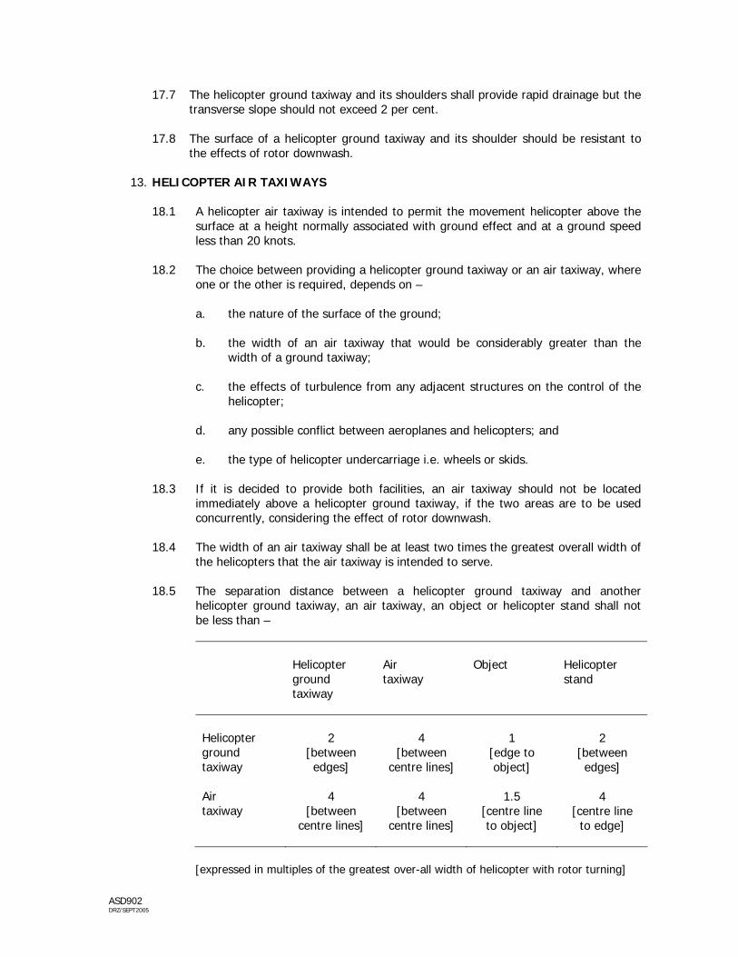
17.7 The helicopter ground taxiway and its shoulders shall provide rapid drainage but the transverse slope should not exceed 2 per cent.
17.8 The surface of a helicopter ground taxiway and its shoulder should be resistant to
the effects of rotor downwash.
13. HELICOPTER AIR TAXIWAYS
18.1 A helicopter air taxiway is intended to permit the movement helicopter above the surface at a height normally associated with ground effect and at a ground speed less than 20 knots.
18.2 The choice between providing a helicopter ground taxiway or an air taxiway, where
one or the other is required, depends on – a. the nature of the surface of the ground; b. the width of an air taxiway that would be considerably greater than the
width of a ground taxiway;
c. the effects of turbulence from any adjacent structures on the control of the helicopter;
d. any possible conflict between aeroplanes and helicopters; and
e. the type of helicopter undercarriage i.e. wheels or skids.
18.3 If it is decided to provide both facilities, an air taxiway should not be located
immediately above a helicopter ground taxiway, if the two areas are to be used concurrently, considering the effect of rotor downwash.
18.4 The width of an air taxiway shall be at least two times the greatest overall width of
the helicopters that the air taxiway is intended to serve.
18.5 The separation distance between a helicopter ground taxiway and another helicopter ground taxiway, an air taxiway, an object or helicopter stand shall not be less than –
Helicopter ground taxiway
Air taxiway
Object
Helicopter stand
Helicopter ground taxiway Air taxiway
2
[between edges]
4
[between centre lines]
4
[between centre lines]
4
[between centre lines]
1
[edge to object]
1.5
[centre line to object]
2
[between edges]
4
[centre line to edge]
[expressed in multiples of the greatest over-all width of helicopter with rotor turning]

ASD902 DRZ/SEPT2005
18.6 The surface of the ground beneath an air taxiway shall -
a. be resistant to the effects of rotor downwash; and
b. be suitable for emergency landings.
18.7 The surface of the ground beneath an air taxiway should provide ground effect.
18.8 The transverse slope of an air taxiway should not exceed 10 per cent and the longitudinal slope should not exceed 7 per cent. In any event, the slopes should not exceed the slope landing limitations of the helicopters the air taxiway is intended to serve.
14. AIR TRANSIT ROUTE
19.1 An air transit route is intended to permit the movement helicopter above the surface, normally at heights not above 30 m above ground level and at ground speeds exceeding 20 knots.
19.2 An air transit route shall only be provided at wide space locations on an aerodrome
to helicopters to fly more quickly while maintaining a safe manoeuvre capability. 19.3 An air transit route will require large amount of airspace which must be kept clear
of all obstacles as well as corresponding areas of ground below them, which must be suitable and of sufficient strength to permit safe emergency landing.
19.4 The width of an air transit route shall not be less than -
a. for operations by day only, 7 times the largest rotor diameter of the
helicopters for which the air transit route is intended;
b. for operations at night, 10 times the largest rotor diameter of the helicopters for which the air transit route is intended;
19.5 Any variation in the direction of the centreline of an air transit route shall not
exceed 120º be designed so as not to necessitate a turn of radius less than 270 m.
19.6 An air transit routes are to be selected so as to permit autorotative or one-engine inoperative landing such that, as a minimum requirement, injury to persons on the ground or damage to property are minimized.
15. APRON
20.1 The helicopter stand shall be of sufficient size to contain a circle of diameter of at least the largest over-all dimension of the largest helicopter the stand is expected to serve.
20.2 The minimum clearance between a helicopter using a helicopter stand and an object or any aircraft in another stand shall not be less than the greatest over-all width of the helicopter that the stand is intended to serve.

ASD902 DRZ/SEPT2005
20.3 When simultaneous hover operations are to be allowed, the separation distances of
4 times the greatest over-all width of the helicopter, with rotors turning, between centre points of the relevant stands are to be applied.
20.4 The slope in any direction on a helicopter stand shall not exceed 2 per cent.
16. LOCATION OF FATO IN RELATION OF RUNWAY OR TAXIWAY
21.1 When a FATO is located near a runway or taxiway, and simultaneous VMC operations are planned, the separation distance between the edge of a runway or taxiway and the edge of a FATO shall not be less than -
If aeroplane mass and/or helicopter mass are
Distance between FATO edge and runway edge or taxiway edge
Up to but not including 2720 kg 2720 kg up to but not including 5760 kg 5760 kg up to but not including 100 000 kg 100 000 kg and over
60 m
120 m
180 m
250 m
21.2 A FATO should not be located near areas where jet engine efflux is likely to cause high turbulence or where aeroplane engine vortex wake generation is likely to exist. Thus it is considered undesirable that a FATO to be located –
a. opposite the threshold and touchdown zones of a runway;
b. within a runway strip; or
c. at taxiway intersection and aircraft holding points serving runways.
21.3 Surface of FATO located near runway or taxiway should be able to resist erosion from engine exhaust and rotor downwash and so minimize the risk of ingestion of loose materials by both aeroplane and helicopter engines.

ASD902 DRZ/SEPT2005
OBSTACLE RESTRICTION 17. OBSTACLE LIMITATION REQUIREMENTS
22.1 The following obstacle limitation surfaces shall be established for a precision approach FATO :
a. take-off climb surface;
b. approach surface;
c. transitional surface; and
d. conical surface.
22.2 The following obstacle limitation surfaces shall be established for a non-precision approach FATO :
a. take-off climb surface; b. approach surface;
c. transitional surface; and
d. conical surface if an inner horizontal is not provided.
22.3 The following obstacle limitation surfaces shall be established for a non-instrument approach FATO :
a. take-off climb surface; and b. approach surface.
22.4 A surface-level heliport shall have at least two take-off climb and approach surfaces, separated by not less than 150º. Surface-level heliport provided with one take-off climb and approach surfaces will be enforced with restrictions on its use.
22.5 The slopes of the surfaces shall not be greater than, and their dimensions not less
than those specified in Appendix B to E. 22.6 All height and slope dimensions shall be relative to a datum which shall be a
horizontal plane whose elevation is the elevation of the FATO.
22.7 New objects or extension of existing objects shall not be permitted above any of the surfaces in 22.1 to 22.3 above except when, in the opinion of the Authority, the new object or extension would be shielded by an existing immovable object.

ASD902 DRZ/SEPT2005
22.8 Existing objects above any of the obstacle limitation surfaces in 22.1 to 22.3 should, as far as practicable be removed except when, in the opinion of the Authority, the object is shielded by an existing immovable object or, after an aeronautical study, that the object would not adversely affect the safety or significantly affect the regularity of operations of helicopters.
22.9 The application of curved take-off climb surfaces may alleviate the problems created by objects infringing these surfaces.
18. APPROACH SURFACE
23.1 The approach surface is an inclined plane or combination of planes sloping upwards from the end of the safety area and centred on a line passing through the centre of the FATO.
23.2 The limits of an approach surface shall comprise –
a. an inner edge horizontal and equal in length to the minimum specified width
of the FATO plus the safety area, perpendicular to the centreline of the approach surface and located at the outer edge of the safety area;
b. two side edges originating at the ends of the inner edge and –
i. for other than a precision approach FATO, diverging uniformly at a
specified rate from the vertical plane containing the centreline of the FATO; or
ii. for a precision approach FATO, diverging uniformly at a specified rate
from the vertical plane containing the centreline of the FATO, to a specified height above the FATO, and then diverging uniformly at a specified rate to a specified final width and continuing thereafter at that width for the remaining length of the approach surface. and
c. an outer edge horizontal and perpendicular to the centreline of the approach
surface and at a specified height above the elevation of the FATO. 23.3 The elevation of the inner edge shall be the elevation of the safety area at the
point the inner edge that is intersected by the centreline of the approach surface.
23.4 The slope[s] of the approach surface shall be measured in the vertical plane containing the centreline of the surface.
23.5 The areas between the inner edge of the approach surface and the safety area
shall have the same characteristics as the safety area. 23.6 The approach path is to be selected so as to permit safe forced landings or one-
engine-inoperative landings such that, as a minimum requirement, injury to occupants of the helicopter, person on the ground or water or damage to property is minimized.

ASD902 DRZ/SEPT2005
19. TRANSITIONAL SURFACE
24.1 The transitional surface is a complex surface along the side of the safety area and part of the side of the approach surface that slope upwards and outwards to the inner horizontal surface or a predetermined height.
24.2 The limits of a transitional surface shall comprise -
a. a lower edge beginning at the intersection of the side of the approach
surface with the inner horizontal surface or beginning at a specified height above the lower edge when an inner horizontal surface is not provided, an extending down the side of the approach surface to the inner edge of the approach surface and from there along the length of the side of the safety area parallel to the centreline of the FATO; and
b. an upper edge located in the plane of the inner horizontal surface, or at a
specified height above the lower edge when the inner horizontal surface is not provided.
24.3 The elevation of a point on the lower edge shall be -
a. along the side of the approach surface – equal to the approach surface at
that point; and b. along the safety area – equal to the elevation of the FATO opposite that
point.
24.4 The transitional surface along the safety area will be curved if the profile of the FATO is curved, or a plane if the profile is a straight line. The intersection of the transitional surface with the inner horizontal, or upper edge when an inner horizontal surface is not provided, will also be curved or a straight line depending on the profile of the FATO.
24.5 The slope of the transitional surface shall be measured in a vertical plane at right
angles to the centreline of the FATO.
20. INNER HORIZONTAL SURFACE
25.1 An inner horizontal surface should be provided where straight-in non-precision instrument approaches are not available at both ends of the FATO.
25.2 The inner horizontal surface is a circular surface located in the horizontal plane above the FATO and its environs.
25.3 The radius of the inner horizontal surface shall be measured from the mid-point of the FATO.
25.4 The height of the inner horizontal surface shall be measured above an elevation datum which is the elevation of the FATO.

ASD902 DRZ/SEPT2005
21. CONICAL SURFACE
26.1 The conical surface is a surface sloping upwards and outwards from the periphery of inner horizontal surface, or from the outer limit of the transitional surface if an inner horizontal surface is not provided.
24.6 The limits of a conical surface shall comprise -
a. a lower edge coincident with the periphery of the inner horizontal surface, or
the outer limit of the transitional surface if an inner horizontal surface is not provided.
b. an upper edge located at a specified height above the inner horizontal
surface, or above the elevation of the FATO if an inner horizontal surface is not provided.
26.2 The slope of the conical surface shall be measured above the horizontal.
22. TAKE-OFF CLIMB SURFACE
27.1 The take-off climb surface is an inclined plane, a combination of planes or, when a turn is involved, a complex surface sloping upwards from the end of the safety area an centred on a line passing through the centre of the FATO.
27.2 The limits of a take-off climb surface shall comprise –
a. an inner edge horizontal and equal in length to the minimum specified width
of the FATO plus the safety area, perpendicular to the centreline of the take-off climb surface and located at the outer edge of the safety area or clearway;
b. two side edges originating at the ends of the inner edge and diverging
uniformly at a specified rate from the vertical plane containing the centreline of the FATO; and
c. an outer edge horizontal and perpendicular to the centreline of the take-off
climb surface and at a specified height above the elevation of the FATO.
27.3 The elevation of the inner edge shall be the elevation of the safety area at the point the inner edge that is intersected by the centreline of the take-off climb surface, except when a clearway is provided, the elevation shall be equal to the highest point on the ground on the same centreline of the clearway.
27.4 In the case of straight take-off climb surface, the slope shall be measured in the vertical plane containing the centreline of the surface.
27.5 In the case of straight take-off climb surface involving a turn, the surface shall be a
complex surface containing the horizontal normals to its centreline and the slope of the centreline shall be the same as for a straight take-off climb surface. The portion of the surface between the inner edge and 30 m above the inner edge shall be straight.

ASD902 DRZ/SEPT2005
27.6 Any variation in the direction of the centreline of the take-off climb surface shall be
designed so as not to necessitate a turn of radius less than 270 m.
27.7 The departure path is to be selected so as to permit safe forced landings or one-engine-inoperative landings such that, as a minimum requirement, injury to occupants of the helicopter, person on the ground or water or damage to property is minimized.
ASD902 DRZ/SEPT2005
VISUAL AIDS 23. A heliport meant for use by day and then only in good visibility conditions will need to
display markings only. On the other hand, if the heliport is intended for use by night or in restricted visibility conditions by day or night it will need to be lighted as well.
24. WIND DIRECTION INDICATOR
29.1 A heliport shall be equipped with at least one wind direction indicator. 29.2 A wind direction indicator shall be constructed so that it gives a clear indication of
the direction of the wind and a general indication of the wind speed.
29.3 A wind direction indicator shall be located so as to indicate the wind conditions over the final approach and take-off area and insuch a way as to be free from the effects of airflow disturbances caused by nearby objects or rotor downwash. It shall be visible from a helicopter in flight, in a hover or on the movement area.
29.4 A wind direction indicator shall be a truncated cone made of lightweight fabric and
shall have minimum dimensions of 2.4 m in length, 0.6 m diameter at larger end and 0.3 m diameter at smaller end.
29.5 The colour of the wind direction indicator should be so selected so as to make it clearly visible and understandable, having regard to background. Where practicable, a single colour, orange should be used. Where a combination of two colours is required to give adequate conspicuity against changing backgrounds, they should be orange and white, or red and white, and should be arranged in five alternate bands the first and last band being the darker colour.
29.6 A wind direction indicator shall at a heliport intended for use at night shall be
illuminated
25. MARKINGS AND MARKERS
30.1 The following markings shall be provided for a heliport -
a. heliport identification marking; b. FATO area marking; and
c. TLOF area marking.

ASD902 DRZ/SEPT2005
30.2 Under certain operational circumstances, the following markings shall also be provided for a heliport -
a. FATO area designation marking; b. aiming point marking; c. touchdown marking; and
d. heliport name marking.
30.3 Where provided, the following markings should be made available -
a. ground taxiway marking; b. air taxiway markers; and
c. air transit route markers.
30.4 HELIPORT IDENTIFICATION MARKING
30.4.1 A heliport identification marking shall be provided at a heliport. 30.4.2 A heliport identification marking shall be located within the FATO area, at
or near the centre of the area. 30.4.3 A heliport identification marking, except for a heliport at a hospital, shall
consist of a letter H, white in colour. The dimensions of the marking shall be no less than those shown in Appendix F.
30.4.4 A heliport identification marking for a heliport at a hospital shall consist of
a letter H, red in colour, on a white cross made of squares adjacent to each of the sides of a square containing the H as shown in Appendix F.
30.4.5 A heliport identification marking shall be orientated so that the cross arm
of the H at right angles to the preferred final approach direction.
30.5 FATO AREA MARKING / MARKERS 30.5.1 A FATO area marking or markers shall be provided at a heliport. 30.5.2 A FATO area marking or markers shall be spaced -
a. for a square or rectangular area, at equal intervals of not more than 50 m with at least three markings on each side including a marking at each corner; and
b. for any other shaped area, including a circular area, at equal intervals
of not more than 10 m with a minimum number of five markings.
ASD902 DRZ/SEPT2005
30.5.3 A FATO area marking shall be a rectangular stripe with a length of 9 m or
one-fifth of the side of the FATO which it defines and a width of 1 m. 30.5.4 A FATO area marker shall be a be of a form similar to that shown in
Appendix G with dimensions of 3 m in length, 1m in width and 0.25 m in height.
30.5.5 Where the marking is used in conjunction with the FATO area designation
marking, its dimension shall be increased by a factor of 3. 30.5.6 A FATO area marking and markers shall be white.
30.6 TLOF AREA MARKING 30.6.1 A TLOF area marking shall be provided at a heliport. 30.6.2 A TLOF area marking shall be located along the perimeter of the TLOF
area. 30.6.3 A TLOF area marking shall be consist of a continuous white line with a
width of at least 30 cm.
30.7 FATO AREA DESIGNATION MARKING
30.7.1 A FATO area designation marking shall be provided where it is necessary to designate the FATO area to the pilot. This marking aid identifies and distinguish one FATO from another.
30.7.2 A FATO area designation marking shall be located at the beginning of the
FATO area. 30.7.3 A FATO area designation marking shall consist of a runway designation
and supplemented by an H.
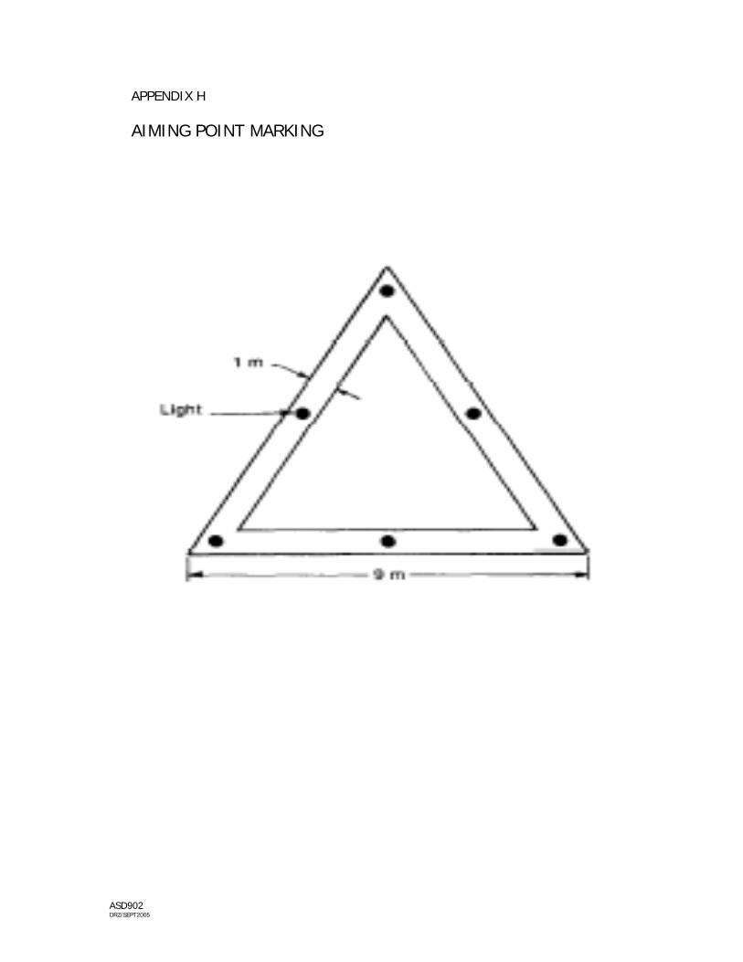
30.8 AIMING POINT MARKING
30.8.1 An aiming point marking shall be provided at a heliport where it is
necessary for a pilot to make an approach to a particular point before proceeding to the TLOF area.
30.8.2 The aiming point marking shall be located within the FATO area. 30.8.3 The aiming point marking shall be an equilateral triangle with the bisector
of one of the angles aligned with the preferred approach path. 30.8.4 The marking shall consist of a continuous white line as shown in Appendix
H.

ASD902 DRZ/SEPT2005
30.9 TOUCHDOWN MARKING 30.9.1 A touchdown marking shall be provided at a heliport where it is necessary
for a helicopter to touchdown in a specific position. 30.9.2 A touchdown marking shall be located so that when a helicopter for which
the marking is intended is positioned, with the main undercarriage inside the marking and the pilot situated over the marking, all parts of the helicopter will be clear of any obstacle by a safe margin.
30.9.3 A touchdown marking shall be a yellow circle and have a line width of at
least 0.5 m.
30.10 HELIPORT NAME MARKING
30.10.1 A heliport name marking shall be provided at a heliport where visual
identification of the heliport is necessary. 30.10.2 A heliport name marking shall be placed on the heliport so as to be visible,
as far as practicable, at all angles above the horizontal. 30.10.3 A heliport name marking shall consist of the name or alphanumeric
designator of the heliport as used in R/T communication. 30.10.4 The characters of the marking shall not be less than 3 m in height. The
colour of the marking should contrast with the background. 30.10.5 A heliport name marking intended for use at night or during conditions of
poor visibility shall be illuminated.
30.11 GROUND TAXIWAY MARKING
30.11.1 A helicopter taxiway should be marked with ground taxiway markings.
30.11.2 Ground taxiway marking shall be located along the centreline of the
helicopter ground taxiway to provide continuous guidance to helicopter stand.
30.11.3 Ground taxiway marking shall be yellow, at least 15 cm width and continuous in length.
30.12 AIR TAXIWAY MARKERS 30.12.1 An air taxiway should be marked with air taxiway markers.
30.12.2 Air taxiway marking shall be located along the centreline of the air taxiway
and shall be spaced an intervals of not more than 30 m on straight sections and 15 m on curves.

ASD902 DRZ/SEPT2005
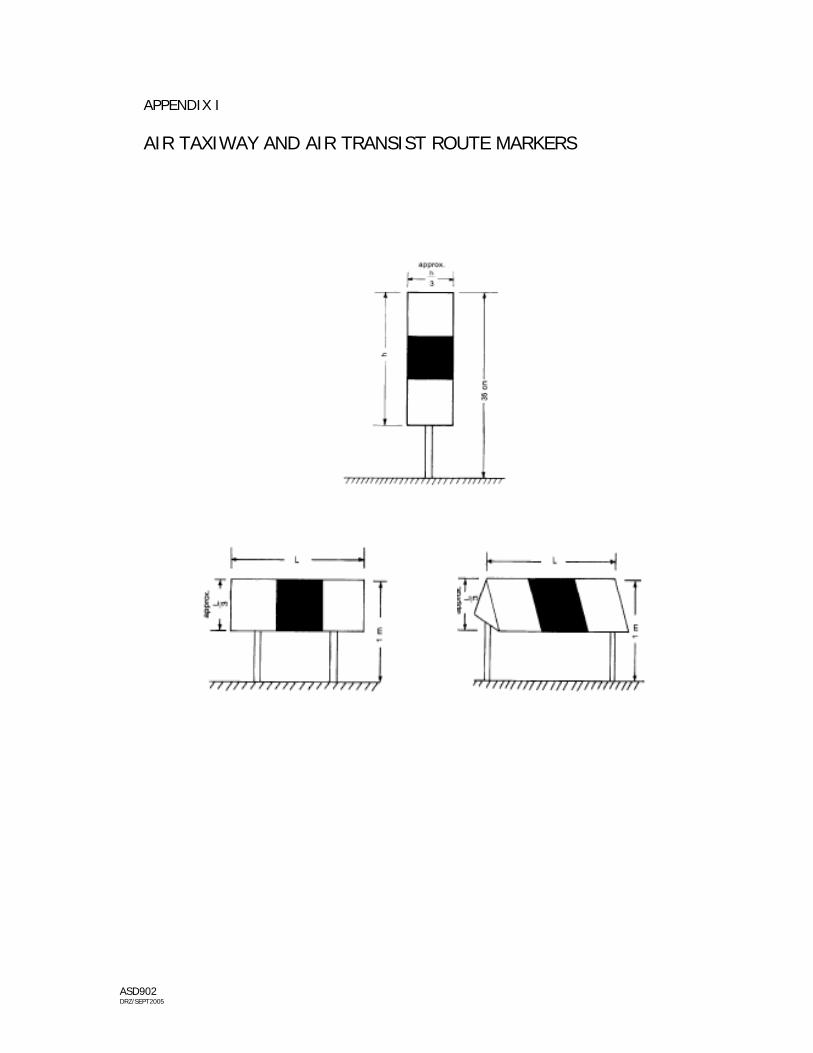
30.12.3 An air taxiway marker shall be frangible and when installed shall not exceed 35 cm above ground level. The surface of the marker as viewed by the pilot shall be a rectangle with height to width ratio of approximately 3:1 and shall have a minimum area of 150 cm² as shown in Appendix I.
30.12.4 An air taxiway marker shall be divided into three equal, horizontal bands
coloured yellow-green-yellow, respectively. If the taxiway is to be used at night, the markers shall be internally illuminated or retro-reflective.
30.13 AIR TRANSIT ROUTE MARKERS 30.13.1 An air transit route should be marked with air transit route markers.
30.13.2 Air transit route markers shall be located along the centreline of the air
transit route and shall be spaced an intervals of not more than 60 m on straight sections and 15 m on curves.
30.13.3 An air transit route marker shall be frangible and when installed shall not exceed 1 m above ground level. The surface of the marker as viewed by the pilot shall be a rectangle with height to width ratio of approximately 3:1 and shall have a minimum area of 1 500 cm² as shown in Appendix I.
30.13.4 An air taxiway marker shall be divided into three equal, vertical bands
coloured yellow-green-yellow, respectively. If the taxiway is to be used at night, the markers shall be internally illuminated or retro-reflective.
26. LIGHTS
31.1 The following lights shall be provided at heliport intended for use by night or in restricted visibility condition by day or night -
a. heliport beacon; b. FATO area lights;
c. TLOF area lights; and
d. obstacle lights.
31.2 Aiming point lights shall be provided where an aiming point is established. 31.3 Taxiway lights shall be provided where a helicopter ground taxiway is established. 31.4 Under certain operational conditions, the following lights are required at heliport
intended for use by night or in restricted visibility condition by day or night -
a. approach lighting system; b. visual alignment guidance system; and
c. helicopter approach path indicator.

ASD902 DRZ/SEPT2005
31.5 HELIPORT BEACON
31.5.1 A heliport beacon shall be provided at a heliport where –
a. long-range visual guidance is considered necessary and is not provided by other visual means;
b. identification of the heliport is difficult due to surrounding lights.
31.5.2 The heliport beacon shall be located on or adjacent to the heliport
preferably at an elevated position and so that it does not dazzle the pilot at short range. Where a heliport beacon is likely to dazzle pilots at short range it may be switched off during the final stages pf the approach and landing.
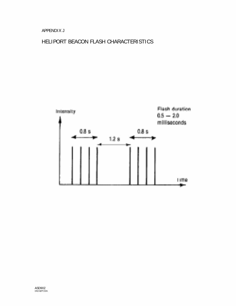
31.5.3 The heliport beacon shall emit repeated series of equispaced short
duration white flashes in the format shown in Appendix J. 31.5.4 The lights from the beacon shall show at all angles of azimuth. 31.5.5 To ensure that pilots are not dazzled during the final stages of the
approach and landing, brilliancy control with 10 per cent and 3 per cent settings or shielding should be provided.
31.6 FATO AREA LIGHTS
31.6.1 FATO area lights shall be provided except that they may be omitted where the FATO area and the TLOF area are coincidental.
31.6.2 FATO area lights shall be placed along the edges of the FATO area. The
lights shall be uniformly spaced as follows -
a. for an area in the form of square or rectangle, at intervals of not more than 50 m with minimum of four lights on each side including a light at each corner;
b. for any other shaped area, including a circular area, at intervals of not
more than 5 m with a minimum of ten lights. 31.6.3 FATO area lights shall be omni-directional lights showing white. Where the
intensity of the lights is to be varied the lights shall show variable white. 31.6.4 FATO area lights shall not exceed a height of 25 cm and shall be inset
when a light extending above the surface would endanger helicopter operations.
ASD902 DRZ/SEPT2005
31.7 TLOF AREA LIGHTS
31.7.1 TLOF area lights shall be provided.
31.7.2 TLOF area lighting system shall consist of one or more of the following -
a. perimeter lights; or b. floodlighting; or
c. arrays of segmented point source lighting [ASPSL] or luminescent
panel [LP] when perimeter lights and floodlighting are not practicable and FATO area lights are available.
31.7.3 TLOF area perimeter lights shall be placed along the edge of the TLOF
area or within a distance of 1.5 m from the edge. 31.7.4 Where the TLOF area is a circle, the perimeter lights shall be -
a. located on straight lines in a pattern which will provide information to pilot on drift displacement; and
b. where, the above is not practicable, evenly spaced around the
perimeter of the TLOF at an appropriate interval. 31.7.5 TLOF area perimeter lights shall be spaced -
a. uniformly at intervals of not more than 5 m. with a minimum of four lights on each side including a light at each corner;
b. evenly, where lights are arranged in a circle, with a minimum of
fourteen lights. 31.7.6 TLOF area perimeter lights shall be fixed omni-directional lights showing
green. 31.7.7 TLOF area perimeter lights shall be inset. 31.7.8 ASPSL or LP lights, if provided to identify FATO/TLOF, shall be placed
along the edge of the FATO/TLOF area except for a circular FATO/TLOF the ASPSL or LP lights shall be located on straight lines circumscribing the area.
31.7.9 LP lights shall meet the following requirements –
a. the minimum number of panels shall be twelve; b. the total length of panels in a pattern shall not be less than 50 per
cent of the length of the pattern;
c. there shall be an odd number with minimum of three panels on each side of the TLOF area including a panel at each corner; and

ASD902 DRZ/SEPT2005
d. the panels shall be equispaced with a distance between adjacent panel ends of not more than 5 m.
31.7.10 LP lights, when used to define the perimeter of FATO/TLOF, shall be fixed
omni-directional lights showing green. 31.7.11 LP lights shall not extend above the surface by more than 2.5 cm. 31.7.12 LP lights shall have a minimum width of 6 cm. The panel housing shall
have the same colour as the marking it defines. 31.7.13 TLOF floodlighting shall be located so as to avoid glare to pilots in flight or
to personnel working on the area. The arrangement and aiming of floodlights shall be such that shadows are kept to a minimum.
31.8 OBSTACLE LIGHTS
31.8.1 Specification on lighting of obstacles included in ASD 402, are equally applicable to heliports.
31.8.2 Obstacles shall be floodlighted if it is not possible to display lights on them.
31.9 AIMING POINT LIGHTS
31.9.1 Where an aiming point is provided at a heliport intended for use at night, aiming point lights shall be provided.
31.9.2 Aiming point lights shall be collocated with the aiming point marking.
31.9.3 Aiming point lights shall form a pattern of at least six omni directional
white lights as shown in Appendix G.
31.9.4 Aiming point lights shall be inset.
31.10 TAXIWAY LIGHTS
31.10.1 Taxiway meant for ground taxiing of helicopters shall be lighted in the same manner as a taxiway meant for use by aeroplanes.
31.11 APPROACH LIGHTING SYSTEM
31.11.1 For non-instrument approaches, an approach lighting system should be provided at a heliport where it is desirable and practicable to indicate a preferred approach direction or to enhance closure rate information to pilots.

ASD902 DRZ/SEPT2005
31.11.2 For instrument approaches, an approach lighting system shall be provided
to provide approach guidance. 31.11.3 For non-instrument approaches, an approach lighting system shall consist
of a row of three lights spaced uniformly at 30 m intervals and of a crossbar 18 m in length at a distance of 90 m from the perimeter of the FATO area as shown in Appendix J. The lights forming the crossbar should be as nearly as practicable in a horizontal straight line at right angles to, and bisected by , the line of the centreline lights and spaced at 4.5 m intervals. Where there is a need to make the final approach course more conspicuous additional lights spaced uniformly at 30 m should be added beyond the crossbar.
31.11.4 For instrument approaches, an approach lighting system shall consist of a
row of at least seven lights extending not less 210 m from the perimeter of the FATO area. The lights are spaced uniformly at 30 m intervals and of a crossbar 18 m in length at a distance of 90 m from the perimeter of the FATO area as shown in Appendix K. The lights forming the crossbar should be as nearly as practicable in a horizontal straight line at right angles to, and bisected by , the line of the centreline lights and spaced at 4.5 m intervals.
31.11.5 The lights shall be omni directional steady white lights except beyond the
crossbar either omni directional steady or flashing white lights may be used.
31.11.6 Sequenced flashing lights may be useful where identification of the
approach lighting system is difficult due to surrounding lights. The flashing lights should have flash frequency of one per second. The flash sequence should commence from the outermost light and progress towards the crossbar.
31.11.7 A suitable brilliancy control should be incorporated to allow for adjustment
of light intensity to meet prevailing conditions -
a. steady lights : 100 per cent, 30 per cent and 10 per cent; and b. flashing lights : 100 per cent, 10 per cent and 3 per cent.
31.12 VISUAL ALIGNMENT GUIDANCE SYSTEM
31.12.1 A visual alignment guidance system should be provided to serve the approach to a heliport where one of the following conditions exists -
a. obstacle clearance, noise abatement or traffic control procedures
require a particular direction to be flown; b. the environment of the heliport provides few visual surface cues; and
c. it is physically impracticable to install an approach lighting system.

ASD902 DRZ/SEPT2005
31.12.2 A visual alignment guidance system shall be located such that a helicopter is guided along the prescribed track towards the FATO area, preferably at the downwind edge of the FATO area.
31.12.3 The light unit shall be frangible and mounted as low as possible. 31.12.4 Where the lights of the system needs to be seen as discrete sources, light
units shall be located such that at the extremes of system coverage the angle subtended between units as seen by the pilots shall not be less than 3 minutes of arc.
31.12.5 The angles subtended between light units of the system and other units comparable or greater intensities shall also not be less than 3 minutes of arc.
31.12.6 The signal format of the alignment guidance system shall include a
minimum of three discrete signal sectors providing “offset to the right”, “on track” and “offset to the left” signals.
31.12.7 The signal format of the alignment guidance system shall be such that
there is no possibility of confusion between the system and any associated visual approach slope indicator or other visual aids.
31.12.8 The system shall avoid the use of same coding as any associated visual
approach slope indicator. 31.12.9 The signal format shall be such that the system is unique and conspicuous
in all operational environments.
31.12.10 The useable coverage of the alignment guidance system shall equal to or better than that of the visual approach slope indicator system, with which it is associated.
31.12.11 A suitable intensity control shall be provided so as to allow adjustment to
meet the prevailing conditions and to avoid dazzling the pilots during approach and landing.
31.12.12 An alignment guidance system shall be capable of adjustment in azimuth
to within ± 5 minutes of arc of the desired approach path.
31.12.13 The angle of azimuth of alignment guidance system shall be such that during an approach a helicopter at the boundary of the “on track” signal will clear all objects in the approach area by a safe margin.

ASD902 DRZ/SEPT2005
31.12.14 The characteristic of the obstacle protection surface is as follows –
SURFACE AND DIMENSIONS
NON-INSTRUMENT
FATO
INSTRUMENT
FATO
Length of inner edge
Width of safety area
Width of safety area
Distance from end of FATO
3 m minimum
60 m
Divergence
10%
15%
Total length
2 500 m
2 500 m
PAPI
0.57º
0.57º
HAPI
0.65º
0.65º
APAPI
0.9º
0.9º
Slope
31.12.15 New objects or extension of existing objects shall not be permitted above the obstacle protection surface, except when, in the opinion of the authority, the new object or extension would be shielded by an existing immovable object.
31.12.16 Existing objects above an obstacle protection surface shall be removed,
except when, in the opinion of the authority, the object is shielded by an existing immovable object, or after aeronautical study it is determined that the object would not adversely affect the safety of operations of helicopters.
31.12.17 In the event of the failure of any component affecting the signal format
the system will automatically switched off.
31.12.18 The light units shall be so designed that deposits of condensation on optical transmitting or reflecting surface will interfere to the least possible extent with the light signal and will not cause spurious or false signals to be generated.
31.12.19 A flight inspection of a new installation shall be conducted to confirm the
correct operation of the system.
31.12.20 A routine scheduled inspection shall be made to ensure the correct operation of the system.

ASD902 DRZ/SEPT2005
31.13 HELICOPTER APPROACH PATH INDICATOR
31.13.1 A helicopter approach path indicator should be provided to serve the approach to a heliport where one of the following conditions exists -
a. obstacle clearance, noise abatement or traffic control procedures
require a particular direction to be flown; b. the environment of the heliport provides few visual surface cues; and
c. the characteristic of the helicopter require a stabilized approach.
31.13.2 A HAPI shall be located such that a helicopter is guided to the desired
position within the FATO area, adjacent to the nominal aiming point and aligned in azimuth with the preferred approach direction.
31.13.3 The light unit shall be frangible and mounted as low as possible.
31.13.4 The signal format of the HAPI shall include four discrete signal sectors
providing an “above slope”, an “on slope”, a “slightly below” and a “below slope” signal.
31.13.5 The signal format of the HAPI shall be shown as in Appendix N. 31.13.6 The signal repetition rate of the flashing sector of the HAPI shall be at
least 2 Hz. 31.13.7 The angular size of the “on slope” sector of the HAPI shall be 45 minutes. 31.13.8 The angular size of the “slightly below” sector of the HAPI shall be 15
minutes. 31.13.9 Colour transition of the HAPI in the vertical plane shall be such as appear
to an observer at a distance of not less than 300 m to occur within a vertical range of not more than three minutes.
31.13.10 The transmission factor of a red or green filter shall not be less than 15
per cent at the maximum intensity.
31.13.11 A full intensity of the red light of the HAPI shall have a Y-coordinate not exceeding 0.320.
31.13.12 A full intensity of the green light of the HAPI shall be within the following
boundaries -
Yellow boundary y = 0.726 – 0.726x White boundary x = 0.625y – 0.041 Blue boundary y = 0.390 – 0.171x
31.13.13 A suitable intensity control shall be provided so as to allow adjustment to
meet the prevailing conditions and to avoid dazzling the pilots during approach and landing

ASD902 DRZ/SEPT2005
31.13.14 A HAPI system shall be capable of adjustment in elevation at any desired angle between 1 degree and 12 degrees above the horizontal with an accuracy of ± 5 minutes of arc.
31.13.15 The angle of azimuth of elevation setting of HAPI shall be such that during
an approach a helicopter at the upper boundary of the “below slope” signal will clear all objects in the approach area by a safe margin.
31.13.16 In the event of vertical misalignment of a unit exceeds ± 0.5º, the will
automatically switched off or if the flashing mechanism fail, no light will be emitted in the failed flashing sector(s).
31.13.17 The light units shall be so designed that deposits of condensation on
optical transmitting or reflecting surface will interfere to the least possible extent with the light signal and will not cause spurious or false signals to be generated.
31.13.18 An obstacle protection surface shall be established when it is intended to
provide HAPI or other visual approach slope indicator.
31.13.19 The characteristic of the obstacle protection surface is as follows –
SURFACE AND DIMENSIONS
NON-INSTRUMENT
FATO
INSTRUMENT
FATO
Length of inner edge
Width of safety area
Width of safety area
Distance from end of FATO
3 m minimum
60 m
Divergence
10%
15%
Total length
2 500 m
2 500 m
PAPI
0.57º
0.57º
HAPI
0.65º
0.65º
APAPI
0.9º
0.9º
Slope
31.13.20 New objects or extension of existing objects shall not be permitted above the obstacle protection surface, except when, in the opinion of the authority, the new object or extension would be shielded by an existing immovable object.
31.13.21 Existing objects above an obstacle protection surface shall be removed,
except when, in the opinion of the authority, the object is shielded by an existing immovable object, or after aeronautical study it is determined that the object would not adversely affect the safety of operations of helicopters.
ASD902 DRZ/SEPT2005
31.13.22 When aeronautical study indicates that existing objects extending above obstacle protection surface could adversely affect the operations of helicopters, one or more of the following measures shall be taken -
a. suitably raise the approach slope of the system; b. reduce the azimuth spread of the system so that the object is outside
the confines of the beam;
c. displace the axis of the system and its associated obstacle protection surface by no more than 5º;
d. suitably displace the FATO area; and
e. install a visual alignment guidance system.

ASD902 DRZ/SEPT2005
RESCUE AND FIRE FIGHTING 27. LEVEL OF PROTECTION
32.1 The level of protection to be provided for rescue and fire fighting shall be based on
the over-all length of the longest helicopter normally using the heliport and in accordance with the heliport fire fighting category.
Category
Helicopter over-all length *
H1
up to but not including 15 m
H2
from 15 m up to but not including 24 m
H3
from 24 m up to but not including 35 m * Helicopter length including the tail boom and rotors
32.2 During anticipated periods of operations by smaller helicopters, the heliport fire fighting category may be reduced to that of the highest category of helicopter planned to use the heliport during that time.
32.3 In the case of a heliport located on an aerodrome, it may be assumed that the
rescue and fire fighting services and equipment provided for aeroplanes will be at least equal to those required for the longest helicopter normally using the facility and that the response time to the helicopter does not exceed two minutes.
28. EXTINGUISHING AGENTS
33.1 The principal extinguishing agent shall be a foam meeting the minimum performance level B.

ASD902 DRZ/SEPT2005
33.2 The amounts of water for foam production and the complementary agents to be
provided shall be in accordance with the heliport fire fighting category.
Foam meeting
Performance level B
Complementary agents
Category
Water
[L]
Discharge rate foam solution [L/min]
Dry
chemical powders
[kg]
or
CO2
H1
500
250
23
45
H2
1 000
500
45
90
H3
1 600
800
90
180
33.3 It is permissible to replace all or part of the amount of water for foam production by complementary agent. The following equivalent shall be used -
1 kg. dry chemical powder or 2 kg. CO2
= 0.66 L water for production of foam meeting performance level B
29. RESPONSE TIME
34.1 A response time not exceeding two minutes in optimum conditions of visibility and surface conditions shall be achieved.
ASD902 DRZ/SEPT2005
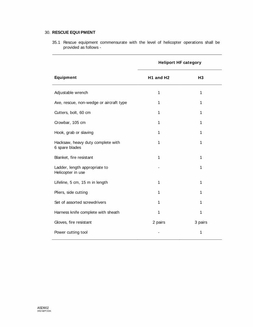
30. RESCUE EQUIPMENT
35.1 Rescue equipment commensurate with the level of helicopter operations shall be provided as follows -
Heliport HF category
Equipment
H1 and H2
H3
Adjustable wrench
1
1
Axe, rescue, non-wedge or aircraft type
1
1
Cutters, bolt, 60 cm
1
1
Crowbar, 105 cm
1
1
Hook, grab or slaving
1
1
Hacksaw, heavy duty complete with 6 spare blades
1
1
Blanket, fire resistant
1
1
Ladder, length appropriate to Helicopter in use
-
1
Lifeline, 5 cm, 15 m in length
1
1
Pliers, side cutting
1
1
Set of assorted screwdrivers
1
1
Harness knife complete with sheath
1
1
Gloves, fire resistant
2 pairs
3 pairs
Power cutting tool
-
1

ASD902 DRZ/SEPT2005
DEVIATIONS 31. The Department of Civil Aviation shall notify and publish deviations from any Standards and
Recommended Practices contained in ICAO Annex 14 in the Aeronautical Information Services publications in compliance to the Article 38 of the Convention on International Civil Aviation.
32. The Appendices to this Directive shall be taken, construed, read and be part of this Directive.
DATO’ IR. KOK SOO CHON Director General Department of Civil Aviation Malaysia Dated: 22 September 2005

ASD902 DRZ/SEPT2005
AMENDMENT RECORD Amendment Number
Amendment Date
Incorporated by
Incorporated on
1/2006 4 Jan 2006 Para 2
4 Jan 2006

ASD902 DRZ/SEPT2005
APPENDIX A PARTICULARS TO BE INCULDED IN AN AERODROME MANUAL PART I : GENERAL General information, including the following – a. name of heliport owner/operator, and address and telephone number[s] at which the
owner/operator can be contacted at all times;
b. purpose and scope of the aerodrome manual;
c. the condition for use of the heliport, including operational limitation and restriction;
d. the system for recording aircraft movements; and
e. obligations of the heliport owner/operator.
PART 2 : PARTICULARS OF THE HELIPORT SITE General information, including the following – a. a plan of the heliport showing the main heliport facilities, including visual aids and non-
visual aids provided; b. a plan showing the approach surfaces and take-off surfaces, and obstacles, within 1000 m
radius of the heliport; and
c. a plan showing the position of the heliport in relation to other infrastructure and terrain within 5000 m radius of the heliport.
PART 3 : PARTICULARS OF THE HELIPORT 3.1 GENERAL INFORMATION
a. the name of the heliport;
b. the type of the heliport;
c. the location of the heliport from the nearest town and nearest aerodrome;
d. the geographical coordinates of the heliport reference point [WGS-84];
e. the elevation of the heliport; and
f. details of heliport beacon [if provided].

ASD902 DRZ/SEPT2005
3.2 HELIPORT DIMENSIONS
a. FATO – type, dimension, true bearing and designation number; b. TLOF – type, dimension, slope and bearing strength in tonnes; c. safety area – type and dimension; d. clearway – dimension and ground profile; e. ground taxiway, air taxiway and air transit route – designation, width and surface
type; f. apron – surface type and helicopter stands.
3.3 GEOGRAPHICAL COORDINATES
a. geometric centre of TLOF;
b. geometric centre of threshold[s] of FATO;
c. ground taxiway, air taxiway and air transit route centerline points;
d. helicopter stands; and
e. significant obstacles in the approach and take-off paths, and the top elevation.
3.4 DECLARED DISTANCES
a. take-off distance available;
b. rejected take-off distance available; and
c. landing distance available.
3.5 VISUAL AIDS
a. visual aids viz. markings and lighting
b. wind direction indicator;
c. VAGS;
d. HAPI.
3.6 RESCUE AND FIRE FIGHTING
a. level of protection.

ASD902 DRZ/SEPT2005
PART 4 : HELIPORT OPERATIONS PROCEDURES 4.1 ATC COORDINATION PROCEDURES
Particulars of procedures for coordination with Air Traffic Services Unit[s], including – a. procedures for arrivals; b. procedures for departures; and c. communication facilities provided.
4.2 HELIPORT REPORTING PROCEDURES
Particulars of procedures for notifying any changes to the infrastructure, facilities and operational procedures, including – a. arrangement for reporting changes; and b. recording of changes.
4.3 ACCESS TO HELIPORT AREA Procedure for the preventing of the unauthorized entry of person[s], vehicles or others
into the heliport area including facilities provided to prevent such occurrence. 4.4 HELIPORT EMERGENCY PLAN
Particulars of the heliport emergency plan, including the following – a. plans for dealing with emergencies occurring at the heliport or in its vicinity; b. details of test for equipment to be used in emergencies, including frequency of
those tests; and c. details of exercise to test the emergency plan, including the frequency of those
exercises.
4.5 RESCUE AND FIRE FIGHTING
Particulars of facilities, equipment, personnel and procedures for meeting the rescue and fire fighting requirements.
4.6 INSPECTION OF HELIPORT
Particulars of procedures for the inspection of the heliport area and obstacle limitation surfaces, including – a. details of inspection intervals and times; b. inspection checklist and logbook; and c. reporting of inspection findings and correction of unsafe conditions.

ASD902 DRZ/SEPT2005
4.7 VISUAL AIDS AND ELECTRICAL SYSTEMS
Particulars of procedures for the inspection and maintenance, aeronautical lights [including obstacle lights], signs, markers and electrical systems – a. arrangements for inspection; b. reporting and recording of inspection findings; c. correction of deficiencies; d. arrangements for routine maintenance; and e. arrangements secondary power supply.
4.8 MAINTENANCE OF HELIPORT AREA
Particulars of procedures for the inspection and maintenance of heliport area – a. arrangements for inspection; b. maintenance of paved areas; c. maintenance of unpaved areas; d. maintenance of markings; and e. maintenance of drainage.
4.9 HELIPORT SAFETY MANAGEMENT
Particulars of procedures to ensure safety during heliport operations - a. helicopter arrival procedures [including engine shut-down]; b. helicopter departing procedure [including engine-start]; c. fuelling procedures and safety precautions; d. protection from rotor downwash; e. apron sweeping and cleaning; f. arrangements for reporting incidents and accidents; and g. personnel safety procedures.
4.10 OBSTACLE CONTROL
Particulars setting out the procedures for - a. controlling obstacles within the authority of owner; b. monitoring development within the obstacle limitation surfaces; and c. coordination for controlling new developments in vicinity of the heliport.
4.11 REMOVAL OF DISABLED AIRCRAFT Particulars of the procedures for removing of a disabled aircraft, including -
a. role of heliport owner and holder of the aircraft certificate of registration; b. arrangements for notifying holder of the aircraft certificate of registration; and

ASD902 DRZ/SEPT2005
c. arrangements for obtaining equipment and personnel to remove aircraft. 4.12 HANDLING OF HAZARDOUS MATERIALS Particulars of the procedures for safe handling and storage of hazardous materials,
including - a. Arrangements for special areas on the heliport for storage of inflammable liquids
[including aviation fuel] and other hazardous material; and b. method for the delivery, storage, dispensing and handling of hazardous material.
4.13 PROTECTION OF NAVAIDS Particulars of the procedures for the protection of sites for radio navigational aids –
a. arrangements for controlling activities in vicinity of navaids installations; b. arrangements for ground maintenance of these installations; and c. arrangements for the installation of signs warning of radiation.
PART 5 : HELIPORT ADMINISTRATION Particulars of the heliport administration, including – a. the heliport organizational chart showing the name and position of key personnel; b. the duty-list and responsibilities of key personnel, in particular the Heliport Manager and
Heliport Duty Officer; and
c. the name and telephone number of the Heliport Manager.

ASD902 DRZ/SEPT2005
APPENDIX B DIMENSION AND SLOPES OBSTACLE LIMITATION SURFACES NON-INSTRUMENT AND NON PRECISION FATO
Non-instrument
Non-Precision
[visual] FATO
[instrument approach] FATO
Helicopter performance class
Surface and dimension
1 2 3
APPROACH Width of inner edge Location of inner edge
Width of safety area boundary Width of safety area boundary
First section Divergence : day / night Length : day / night Outer width : day / night Slope [maximum] Second section Divergence : day / night Length : day / night Outer width : day / night Slope [maximum] Third section Divergence Length : day / night Outer width : day / night Slope [maximum]
10% / 15%
245 m / 245 m 49 m / 73.5 m
8%
10% / 15%
12.5%
parallel
15%
10% / 15%
245 m / 245 m 49 m / 73.5 m
8%
10% / 15%
12.5%
parallel
15%
10% / 15%
245 m / 245 m 49 m / 73.5 m
8%
10% / 15%
12.5%
parallel
15%
16%
2 500 m 890 m 3.33 %
- - - - - - - -
INNER HORIZONTAL Height Radius
- -
- -
- -
45 m 2 000 m
CONICAL Slope Height
- -
- -
- -
5% 55 m
TRANSITIONAL Slope Height
- -
- -
- -
20% 45 m
Slope and length enables helicopters to decelerate for landing while observing “avoid” areas The width of the inner edge shall be added to this dimension Determined by the distance from the inner edge to the point where the divergence produces a width of 7 rotor diameters for day operations and
10 rotor diameters for night operations Seven rotor diameters for day operations and 10 rotor diameters for night operations Determined by the distance from the inner edge to where the approach surface reaches a height of 150 m above the elevation of the inner edge

ASD902 DRZ/SEPT2005
APPENDIX C DIMENSION AND SLOPES OBSTACLE LIMITATION SURFACES
PRECISION APPROACH FATO
3º approach
6º approach
Height above FATO
Height above FATO
Surface and dimension
90 m
[300 ft]
60 m
[200 ft]
45 m
[150 ft]
30 m
[100 ft]
90 m
[300 ft]
60 m
[200 ft]
45 m
[150 ft]
30 m
[100 ft]
APPROACH
Length of inner edge Distance from end of FATO Divergence each side to height above FATO Distance to height above FATO Width at height avbove FATO Divergence to parallel section Width of parallel section Distance to outer edge Width at outer edge Width at outer edge Slope of first section Length of first section Slope of second section Length of second section Total length of surface
90 m
60 m
25%
1 745 m
962 m
15%
2 793 m
1 800 m
5 462 m
1 800 m
2.5%
3 000 m
3%
2 500 m
10 000 m
90 m
60 m
25%
1 163 m
671 m
15%
3 763 m
1 800 m
5 074 m
1 800 m
2.5%
3 000 m
3%
2 500 m
10 000 m
90 m
60 m
25%
872 m
562 m
15%
4 246 m
1 800 m
4 882 m
1 800 m
2.5%
3 000 m
3%
2 500 m
10 000 m
90 m
60 m
25%
581 m
380 m
15%
4 733 m
1 800 m
4 686 m
1 800 m
2.5%
3 000 m
3%
2 500 m
10 000 m
90 m
60 m
25%
870 m
521 m
15%
4 250 m
1 800 m
3 380 m
1 800 m
5%
1 500 m
6%
1 250 m
8 500 m
90 m
60 m
25%
580 m
380 m
15%
4 733 m
1 800 m
3 187 m
1 800 m
5%
1 500 m
6%
1 250 m
8 500 m
90 m
60 m
25%
435 m
307.5 m
15%
4 975 m
1 800 m
3 090 m
1 800 m
5%
1 500 m
6%
1 250 m
8 500 m
90 m
60 m
25%
290 m
235 m
15%
5 217 m
1 800 m
2 993 m
1 800 m
5%
1 500 m
6%
1 250 m
8 500 m
CONICAL Slope Height
5% 55 m
5% 55 m
5% 55 m
5% 55 m
5% 55 m
5% 55 m
5% 55 m
5% 55 m
TRANSITIONAL Slope Height
14.3% 45 m
14.3% 45 m
14.3% 45 m
14.3% 45 m
14.3% 45 m
14.3% 45 m
14.3% 45 m
14.3% 45 m
ASD902 DRZ/SEPT2005
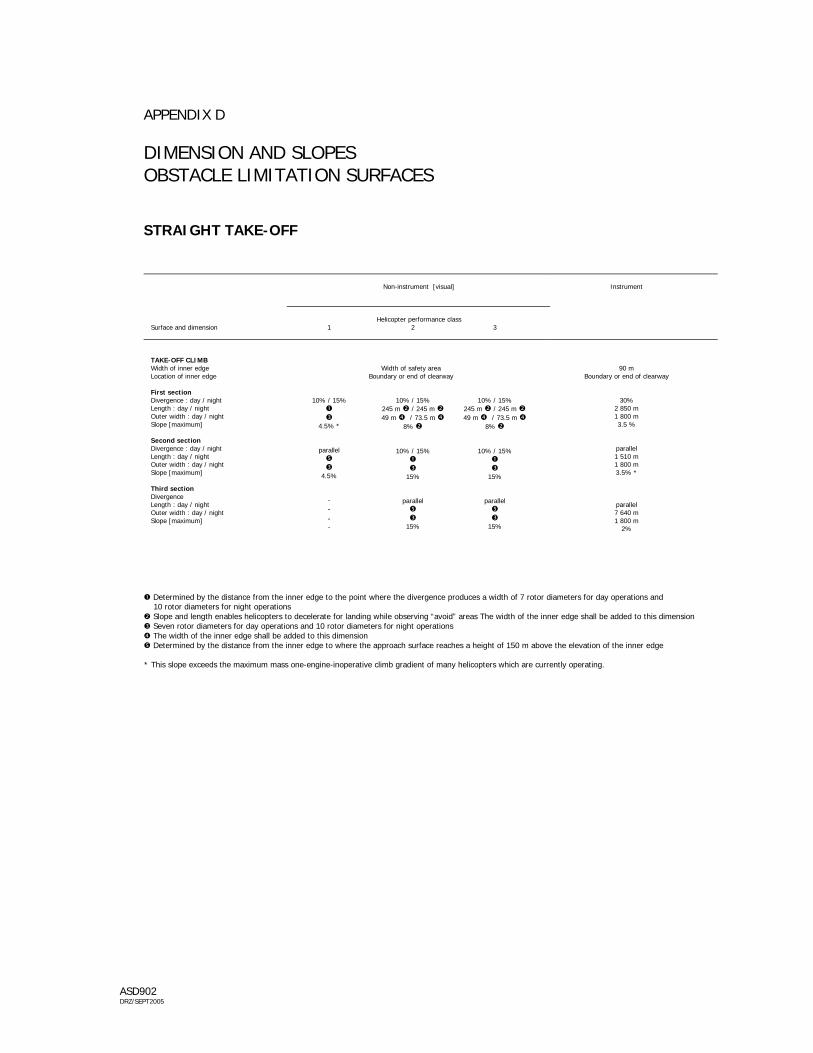
APPENDIX D DIMENSION AND SLOPES OBSTACLE LIMITATION SURFACES STRAIGHT TAKE-OFF
Non-instrument [visual]
Instrument
Helicopter performance class
Surface and dimension
1 2 3
TAKE-OFF CLIMB Width of inner edge Location of inner edge
Width of safety area Boundary or end of clearway
90 m Boundary or end of clearway
First section Divergence : day / night Length : day / night Outer width : day / night Slope [maximum] Second section Divergence : day / night Length : day / night Outer width : day / night Slope [maximum] Third section Divergence Length : day / night Outer width : day / night Slope [maximum]
10% / 15%
4.5% *
parallel
4.5% - - - -
10% / 15%
245 m / 245 m 49 m / 73.5 m
8%
10% / 15%
15%
parallel
15%
10% / 15%
245 m / 245 m 49 m / 73.5 m
8%
10% / 15%
15%
parallel
15%
30%
2 850 m 1 800 m 3.5 %
parallel 1 510 m 1 800 m 3.5% *
parallel 7 640 m 1 800 m
2%
Determined by the distance from the inner edge to the point where the divergence produces a width of 7 rotor diameters for day operations and 10 rotor diameters for night operations
Slope and length enables helicopters to decelerate for landing while observing “avoid” areas The width of the inner edge shall be added to this dimension Seven rotor diameters for day operations and 10 rotor diameters for night operations The width of the inner edge shall be added to this dimension Determined by the distance from the inner edge to where the approach surface reaches a height of 150 m above the elevation of the inner edge
* This slope exceeds the maximum mass one-engine-inoperative climb gradient of many helicopters which are currently operating.

ASD902 DRZ/SEPT2005
APPENDIX E CRITERIA FOR CURVED TAKE-OFF CLIMB / APPROACH AREA NON-INSTRUMENT FINAL APPROACH AND TAKE-OFF
Facility
Requirement
Directional change Radius of turn on centreline Sistance to inner gate * Width of inner gate Width of outer gate Elevation of inner and outer gates Slope Divergence Total length of area
As required [120º max.] Not less than 270 m. a. For
performance class 1 helicopters – not less than 305 m from end of safety area or helicopter clearway.
b. For
performance class 2 and 3 helicopters – not less than 370 m from end of FATO.
For day use Width of inner edge plus 20% of distance to inner gate. For night use Width of inner edge plus 30% of distance to inner gate. For day use Width of inner edge plus 20% of distance to inner gate out to minimum width of 7 rotor diameters. For night use Width of inner edge plus 30% of distance to inner gate out to minimum width of 10 rotor diameters. Determined by the distance from the inner edge and the designated gradient[s]. As in Appendix A, B or C. As in Appendix A, B or C. As in Appendix A, B or C.
* This is the minimum distance required prior to initiating a turn after take-off or completing a turn in the final phase
Note : More than one turn may be necessary in the total length of the take-off climb / approach area. The same criteria will apply for each subsequent turn except that the widths of the inner and outer gates would normally be the maximum width of the area.

ASD902 DRZ/SEPT2005
APPENDIX F HELIPORT IDENTIFICATION MARKING [shown with hospital cross]
... ...

ASD902 DRZ/SEPT2005
APPENDIX G FATO AREA MARKER
ASD902 DRZ/SEPT2005
APPENDIX H AIMING POINT MARKING
ASD902 DRZ/SEPT2005
APPENDIX I AIR TAXIWAY AND AIR TRANSIST ROUTE MARKERS
ASD902 DRZ/SEPT2005
APPENDIX J HELIPORT BEACON FLASH CHARACTERISTICS

ASD902 DRZ/SEPT2005
APPENDIX K APPROACH LIGHTING SYSTEM

ASD902
DR
Z/SEPT2005
APPEND
IX L ISO
CAND
ELA DIAG
RAM
S OF LIG
HTS FO
R H
ELIPORTS
G"..,
'~l!1loj1
6:IE oji
i 001 o:l-l
EI .... ~n
1_.-~I"l'!l~J
a., ... !11
':lJ' tGMi
2!1' S~oj1
:ll' ~
[01'
3' [Q~o:l
~ 10011 -11Il' AmlIh . tal'
ItmI"nS-fiM~nI L't»<t1ml,ltt n ..,..~(ttl ~tt
EIlI'''!I1
~ I S5 oi'nl
6Il' S5 oi'nl
411' 9J oi'nl
\lJ' 15oi)]'
a.,·.lcnf:1 :ll' III od'd
~<B ill' 11>1
111'.£>211' Bo:l I: I [5 oi'nl
5oi'nl -~ID' .I.t .. .!t J . 11Il'
I(JI,B, 13' !5 o:l r,piJ11~1
S'l: B IIl' 1 lil a! Ib t.l:rJl-bltII:lo:Inllldllml
2'SB !I' I 15a1 _I9l'.lJlTJII .I9J'
~11tl
,\ ','iI--Adj.f,m'1 .... ,lIflil .. ;tI.rd. II ..... ~ -""".yI.:tIrt-1r L'RI"d lra'.~ .I!.I'i' Mv.a!biI ~~.s" t.J ,iJJ1:I'\7NS..
Illlr'*',6- T .. :<t.g , "'.d Ikll .. ,
1"-'1"111""ltl'
U1t»mtpDll
E1_
m' :9lal'
l ' l!DaiI
.' 11CDaiI 2l2" 2 !lIlaiI Irll ' • "",or
A' 11CDaiI -lBr .tmJlh +1lI1l'
l'«1 ~ I!P1
'Elld •• It~)'
luw~ 1-_<II1>Im1
Qlmal_--. 6:!i'li aI 3~ aI I II'S aI 'iSai
G1hl:
EIiI\',fm
r." is <>I
'1' :9l0ll
Il' l:Bl00I 5' '2CD00i
'F 150<>1 (f iSOil
-1Br ,lMgh +1Br l'«1~ .,11
lult~ 2-.I;!mD1 ~It , ~"'\' IlC'l'~~
t(bj[
50011
~
[0]'
10<>1 -11Il'
Itmll:lnS - fin.f iWm11 nI L't:o<:tiNI,ltt '""
ti-Giid:lljtt
EIo'ltbn
r." iSOor
'1' 29]0<>11
Il' 39]0<>11 5' '1!IXI>J?
2' 29]Oor (f ~
-IlIIl" .tmJlh +1B1' (Itb~
' ElldI.'~j'
IlIlIr,ji1l13 -.I;!mD11 ~ IIIoIt1g'
EiIrI.ICIl f:1
8J'<B Q(f 11>1
1II'<E!.20' Bm
I(JI,B I:!' jS <>I
5'l: B I(f lIl ai
!ij oon!
.tJ' 9] oxIn!
~ 15001:1'
V' III .to'
j(f 13 oon!
(f
-11Il' .ur ... t , +11Il' ~"Ii1tl
ll3t.l:rll- l:IJ:I'JI:x a:dllldliNI' umomtpms
'!l!Ir-Adj':m'T;IWS ~t1fIH!II~.rll::t(l ~I F3:1111 _ ..... y,':tIrt_1y 1'IlIu.o'l fII',~
.I!.I'i' MvJ.!bi' ij ~.s, ,".1 li.t~ rJlgNS..
Illl .-,,6- T"'~<IlI . "_d 11.<11 .. , ~'I"1IIlIIllt ll

ASD902 DRZ/SEPT2005
APPENDIX M VISUAL ALIGNMENT GUIDANCE SYSTEM
,. '! -'.0
,. . - '! !' , . -,. '! -'.0
,. . - '! !' , . -

ASD902 DRZ/SEPT2005
APPENDIX N HELICOPTER APPROACH PATH INDICATOR