marking of army airfield heliport · pdf filemarking of army airfield-heliport operational and...
TRANSCRIPT
UFC 3-260-05A 16 January 2004
UNIFIED FACILITIES CRITERIA (UFC)
MARKING OF ARMY AIRFIELD HELIPORT OPERATIONAL AND
MAINTENANCE FACILITIES
APPROVED FOR PUBLIC RELEASE; DISTRIBUTION UNLIMITED

UFC 3-260-05A 16 January 2004
1
UNIFIED FACILITIES CRITERIA (UFC)
MARKING OF ARMY AIRFIELD HELIPORT OPERATIONAL AND MAINTENANCE FACILITIES
Any copyrighted material included in this UFC is identified at its point of use. Use of the copyrighted material apart from this UFC must have the permission of the copyright holder. U.S. ARMY CORPS OF ENGINEERS (Preparing Activity) NAVAL FACILITIES ENGINEERING COMMAND AIR FORCE CIVIL ENGINEER SUPPORT AGENCY Record of Changes (changes are indicated by \1\ ... /1/) Change No. Date Location
This UFC supersedes TM 5-823-4, dated 7 July 1987. The format of this UFC does not conform to UFC 1-300-01; however, the format will be adjusted to conform at the next revision. The body of this UFC is the previous TM 5-823-4, dated 7 July 1987.
UFC 3-260-05A 16 January 2004
2
FOREWORD \1\ The Unified Facilities Criteria (UFC) system is prescribed by MIL-STD 3007 and provides planning, design, construction, sustainment, restoration, and modernization criteria, and applies to the Military Departments, the Defense Agencies, and the DoD Field Activities in accordance with USD(AT&L) Memorandum dated 29 May 2002. UFC will be used for all DoD projects and work for other customers where appropriate. All construction outside of the United States is also governed by Status of forces Agreements (SOFA), Host Nation Funded Construction Agreements (HNFA), and in some instances, Bilateral Infrastructure Agreements (BIA.) Therefore, the acquisition team must ensure compliance with the more stringent of the UFC, the SOFA, the HNFA, and the BIA, as applicable. UFC are living documents and will be periodically reviewed, updated, and made available to users as part of the Services’ responsibility for providing technical criteria for military construction. Headquarters, U.S. Army Corps of Engineers (HQUSACE), Naval Facilities Engineering Command (NAVFAC), and Air Force Civil Engineer Support Agency (AFCESA) are responsible for administration of the UFC system. Defense agencies should contact the preparing service for document interpretation and improvements. Technical content of UFC is the responsibility of the cognizant DoD working group. Recommended changes with supporting rationale should be sent to the respective service proponent office by the following electronic form: Criteria Change Request (CCR). The form is also accessible from the Internet sites listed below. UFC are effective upon issuance and are distributed only in electronic media from the following source: • Whole Building Design Guide web site http://dod.wbdg.org/. Hard copies of UFC printed from electronic media should be checked against the current electronic version prior to use to ensure that they are current. AUTHORIZED BY: ______________________________________ DONALD L. BASHAM, P.E. Chief, Engineering and Construction U.S. Army Corps of Engineers
______________________________________DR. JAMES W WRIGHT, P.E. Chief Engineer Naval Facilities Engineering Command
______________________________________ KATHLEEN I. FERGUSON, P.E. The Deputy Civil Engineer DCS/Installations & Logistics Department of the Air Force
______________________________________Dr. GET W. MOY, P.E. Director, Installations Requirements and Management Office of the Deputy Under Secretary of Defense (Installations and Environment)
TM 5-823-4
TECHNICAL MANUAL
MARKING OFARMY AIRFIELD-HELIPORT
OPERATIONAL AND MAINTENANCEFACILITIES
This copy is a reprint which includes current pages from Change 1.
HEADQUARTERS, DEPARTMENT OF THE ARMYJULY 1987
TM 5-823-4C 1
CHANGE HEADQUARTERSDEPARTMENT OF THE ARMY
NO. 1 WASHINGTON, DC, 25 April 1988
MARKING OF ARMY AIRFIELD-HELIPORTOPERATIONAL AND MAINTENANCE FACILITIES
This change updates referenced publications and adds a new chapter for marking and painting of groundreceiver checkpoints.
TM 5-823-4, 7 July 1987, is changed as follows:1. New or revised material is indicated by a vertical bar in the margin. Where an entire chapter, section, orillustration is added or revised, the vertical bar is placed opposite the identification number and title.2. Remove old pages and insert new pages as follows:
Remove pages Insert pages
i and ii ........................................................................ i and ii2-1 and 2-2 ................................................................2-1 and 2-27-1 and 7-2 ................................................................7-1 and 7-2
................................................................8-1A-1........................................................................... ..A-1
3. File this transmittal sheet in front of the publication.
The proponent agency of this publication is the Office of the Chief of Engineers, United StatesArmy. Users are invited to send comments and suggested improvements on DA Form 2028(Recommended Changes to Publications and Blank Forms) direct to HQDA (DAEN-ECE-G), WASHDC 20314-1000.
By Order of the Secretary of the Army:
Carl E. VuonoGeneral, United States Army
Chief of Staff
Official:
R.L. DILWORTHBrigadier General, United States Army
The Adjutant General
DISTRIBUTION:To be distributed in accordance with DA Form 12-34B, requirements for Army Airfield Pavements.
}

*TM 5-823-4TECHNICAL MANUAL HEADQUARTERS
DEPARTMENT OF THE ARMYNo. 5-823-4 WASHINGTON, D. C., 7 July 1987
MARKING OF ARMY AIRFIELD-HELIPORTOPERATIONAL AND MAINTENANCE FACILITIES
Paragraph PageCHAPTER 1. GENERAL
Purpose ...................................................................................................... 1-1 1-1Scope .......................................................................................................... 1-2 1-1Exceptions................................................................................................... 1-3 1-1Definitions ................................................................................................... 1-4 1-1
CHAPTER 2. MARKING OF SERVICEABLE RUNWAYS AND TAXIWAYS AT AIRFIELDSGeneral ....................................................................................................... 2-1 2-1Marking with paint ....................................................................................... 2-2 2-1Application................................................................................................... 2-3 2-1Marking practices ........................................................................................ 2-4 2-5Runway markings........................................................................................ 2-5 2-5Taxiway markings ....................................................................................... 2-6 2-8Stabilized areas........................................................................................... 2-7 2-14Runway shoulder marking........................................................................... 2-8 2-14Aircraft parking ramps, tie down and mooring areas .................................. 2-9 2-14
CHAPTER 3. MARKING OF SERVICEABLE RUNWAYS AND TAXIWAYS AT HELIPORTSGeneral ....................................................................................................... 3-1 3-1Marking with paint ....................................................................................... 3-2 3-1Runway marking ......................................................................................... 3-3 3-1Taxiway marking requirements ................................................................... 3-4 3-1Heliport identification marker requirements ................................................ 3-5 3-1
CHAPTER 4. MARKING OF OVERRUN AND SHOULDER AREAS AT HELIPORTSGeneral ....................................................................................................... 4-1 4-1Overrun areas ............................................................................................. 4-2 4-1Runway-shoulder areas .............................................................................. 4-4 4-1Taxiway, taxilane, apron, hardstand, and engine run-up shoulder areas ... 4-4 4-1Detail requirements ..................................................................................... 4-5 4-1
CHAPTER 5. MARKING AND LIGHTING OF CLOSED ORHAZARDOUS AREAS ON AIRFIELDS OR HELIPORTS
Permanently closed runways and taxiways................................................. 5-1 5-1Temporarily closed runways and taxiways.................................................. 5-2 5-1Closed airfields and heliports...................................................................... 5-3 5-1Hazardous areas......................................................................................... 5-4 5-1Stabilized areas........................................................................................... 5-5 5-1Runway shoulder areas .............................................................................. 5-6 5-1
CHAPTER 6. MARKING OF COMPASS SWINGING BASESGeneral ....................................................................................................... 6-1 6-1Magnetic effects .......................................................................................... 6-2 6-1Pavement grade.......................................................................................... 6-3 6-1Alinement markings .................................................................................... 6-4 6-1Clearances .................................................................................................. 6-5 6-1Marking with paint ....................................................................................... 6-6 6-1Application of paint...................................................................................... 6-7 6-1
CHAPTER 7. MARKING OF OBSTRUCTIONS TO AIR NAVIGATIONGeneral ....................................................................................................... 7-1 7-1
*This manual supersedes TM 5-823-4, dated January 1977, including all changes.
Change 1 i

TM 5-823-4
Paragraph Page
Detail requirements ..................................................................................... 7-2 7-1Lighting of airfields, heliports, and obstructions .......................................... 7-3 7-1Purpose of marking..................................................................................... 7-4 7-1Omission of standard marking .................................................................... 7-5 7-1Colors.......................................................................................................... 7-6 7-1Painting ....................................................................................................... 7-7 7-1Patterns....................................................................................................... 7-8 7-2Markers ....................................................................................................... 7-9 7-6Special markings......................................................................................... 7-10 7-6
CHAPTER 8. GROUND RECEIVER CHECKPOINTSLocation....................................................................................................... 8-1 8-1Painting ....................................................................................................... 8-2 8-1
APPENDIX A. REFERENCES............................................................................................ A-1
LIST OF FIGURES
Figure 2-1. Runway markings.(2) 2-2. Precision instrument runway marking.
2-3. Visual and nonprecision marking.2-4. Runway numbers and letters.2-5. Marking for displaced thresholds, blast pads and stopways.
(2) 2-6. Taxiway/runway intersection marking.2-7. Runway shoulder markings.2-8. Holding position markings.3-1. Guidelines for marking runways and taxiways at heliports.3-2. Helipad marking pattern.4-1. Marking of heliport overrun and shoulder area.4-2. Marking of shoulders for heliport parking and maintenance aprons and taxiways.5-1. Closed runway and taxiway markings.6-1. Army airfield-heliport compass swinging base.7-1. Painting and lighting of chimneys, poles, towers and similar obstructions.7-2. Painting and lighting of water towers, storage tanks and similar obstructions.7-3. Painting and lighting of water towers and similar obstructions.7-4. Painting of single pedestal water tower by teardrop pattern.8-1. Ground receiver checkpoint markings.
Change 1 ii
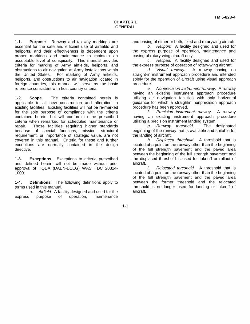
TM 5-823-4CHAPTER 1GENERAL
1-1. Purpose. Runway and taxiway markings areessential for the safe and efficient use of airfields andheliports, and their effectiveness is dependent uponproper markings and maintenance to maintain anacceptable level of conspicuity. This manual providescriteria for marking of Army airfields, heliports, andobstructions to air navigation at Army installations withinthe United States. For marking of Army airfields,heliports, and obstructions to air navigation located inforeign countries, this manual will serve as the basicreference consistent with host country criteria.
1-2. Scope. The criteria contained herein isapplicable to all new construction and alteration toexisting facilities. Existing facilities will not be re-markedfor the sole purpose of compliance with the criteriacontained herein, but will conform to the prescribedcriteria when remarked for scheduled maintenance orrepair. Those facilities requiring higher standardsbecause of special functions, mission, structuralrequirement, or importance of strategic value, are notcovered in this manual. Criteria for these and furtherexceptions are normally contained in the designdirective.
1-3. Exceptions. Exceptions to criteria prescribedand defined herein will not be made without priorapproval of HQDA (DAEN-ECEG) WASH DC 20314-1000.
1-4. Definitions. The following definitions apply toterms used in this manual.
a. Airfield. A facility designed and used for theexpress purpose of operation, maintenance
and basing of either or both, fixed and rotarywing aircraft.b. Heliport. A facility designed and used for
the express purpose of operation, maintenance andbasing of rotary-wing aircraft only.
c. Helipad. A facility designed and used forthe express purpose of operation of rotary-wing aircraft.
d. Visual runway. A runway having nostraight-in instrument approach procedure and intendedsolely for the operation of aircraft using visual approachprocedure.
e. Nonprecision instrument runway. A runwayhaving an existing instrument approach procedureutilizing air navigation facilities with only horizontalguidance for which a straightin nonprecision approachprocedure has been approved.
f. Precision instrument runway. A runwayhaving an existing instrument approach procedureutilizing a precision instrument landing system.
g. Runway threshold. The designatedbeginning of the runway that is available and suitable forthe landing of aircraft.
h. Displaced threshold. A threshold that islocated at a point on the runway other than the beginningof the full strength pavement and the paved areabetween the beginning of the full strength pavement andthe displaced threshold is used for takeoff or rollout ofaircraft.
i. Relocated threshold. A threshold that islocated at a point on the runway other than the beginningof the full strength pavement and the paved areabetween the former threshold and the relocatedthreshold is no longer used for landing or takeoff ofaircraft.
1-1

TM 5-823-4CHAPTER 2
MARKING OF SERVICEABLE RUNWAYS AND TAXIWAYS AT AIRFIELDS
2-1. General. The criteria contained within thischapter conforms to Federal Aviation Administration(FAA) Advisory Circular (AC) No. 150-5340-1E withminor exceptions. Where the criteria stated herein is inconflict with the AC 150/5340-1E, this manual will prevail.
2-2. Marking with paint. Initial marking of runwaysand taxiways at airfields should be done as soon aspossible, subsequent to the required curing period. Re-marking or revising existing marks should beaccomplished as often as necessary. The effectivenessof markings is heavily dependent upon their propermaintenance to provide maximum contrast withbackgrounds.
a. Color marking. All runways will be markedwith white reflective paint. Taxiways will be marked withyellow nonreflective paint.
(1) Runways. Reflective paints used tomark or re-mark runways will conform to FederalSpecifications (Fed. Spec.) TT-P45E or TT-P-1952.
(2) Taxiways. Nonreflective paints used tomark or re-mark taxiways will conform to FederalSpecifications (Fed. Spec.) TT-P-85E or TT-B-1325.
b. Application of paint. Painted markings willbe applied to paved areas only after the pavements havebeen allowed to cure thoroughly. New pavementsurfaces will be allowed to cure for a minimum of 30days before application of marking materials. Care willbe taken to insure that the pavement surface is dry andclean prior to painting.
(1) Rigid pavements. When paintedmarkings are to be applied to rigid pavements that havebeen cured with a membrane-type curing compound, thesurface to be painted will be cleaned thoroughly and thecuring compound removed by sandblasting prior topainting.
(2) Flexible pavements. Flexiblepavements will be allowed to cure as long as possiblebefore painting (see paragraph 2-2b. above also). Toprevent undue softening of the bitumen by the paint, andpickup, displacement, or discoloration by tires of traffic,the maximum drying time as prescribed by the paint
manufacturer or contract specifications will be enforced.
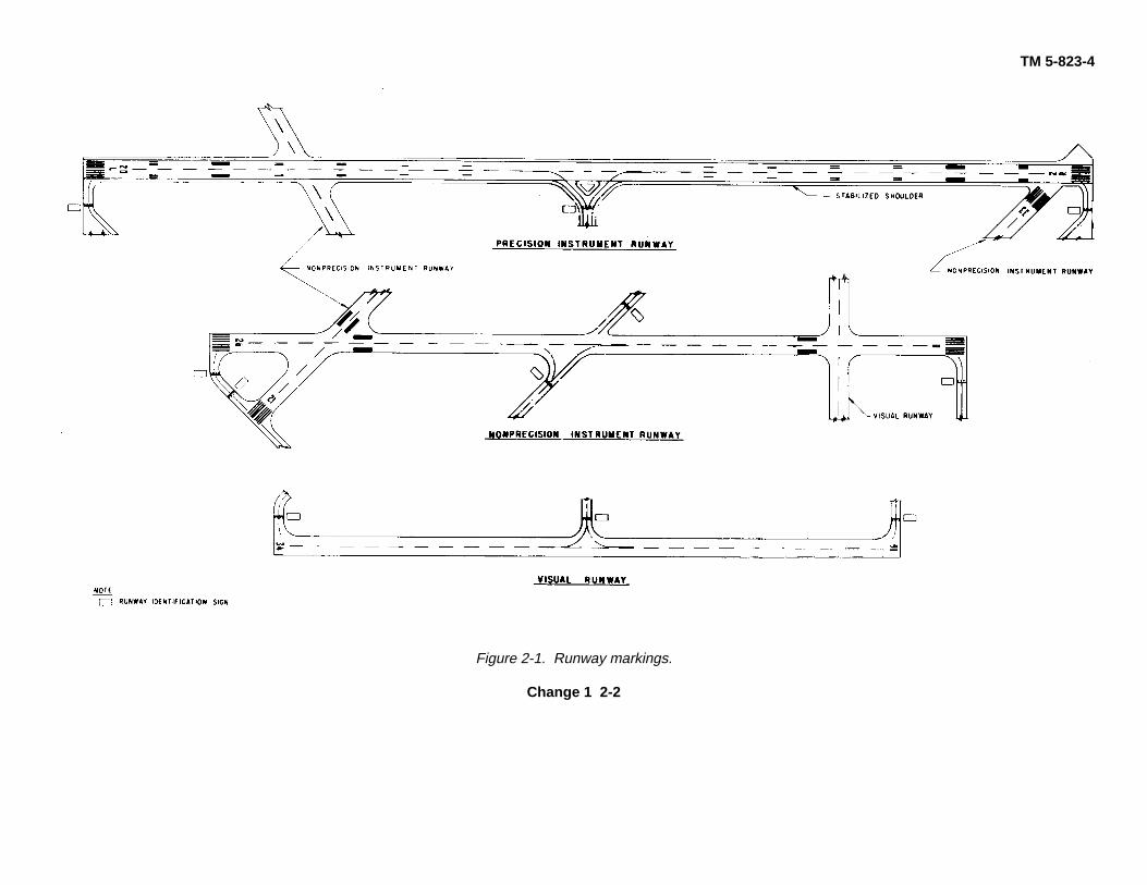
2-3. Application. The marking elements used forthe various runway classifications are illustrated in figure2-1. Markings for precision instrument runways areshown in figure 2-2, and markings for nonprecisioninstrument and visual runways are shown in figure 2-3.A runway should be marked in accordance with itspresent usage (visual, nonprecision instrument, orprecision instrument) unless upgrading to a higherclassification is imminent. The marking elements foreach runway classification, which should never be lessbut which may contain additional elements normally usedon higher runway classification, are as follows:
a. Visual runway.(1) Centerline marking.(2) Designation marking.(3) Threshold marking (on runways used
or intended to be used by international commercial airtransport).
(4) Fixed distance marking (on runways4,000 feet or longer used by jet aircraft).
(5) Holding position markings (fortaxiway/runway intersections).
b. Nonprecision instrument runway.(1) Centerline marking.(2) Designation marking.(3) Threshold marking.(4) Fixed distance marking (on runways
4,000 feet or longer used by jet aircraft).(5) Holding position markings (for
taxiway/runway intersections and instrument landingsystem (ILS) critical areas).
c. Precision instrument runway.(1) Centerline marking.(2) Designation marking.(3) Threshold marking.(4) Fixed distance marking.(5) Touchdown zone marking.(6) Side stripes.(7) Holding position markings (for
taxiway/runway intersections and ILS critical areas).
Change 1 2-1
TM 5-823-4
Figure 2-1. Runway markings.
Change 1 2-2

TM 5-823-4
Figure 2-2. Precision instrument runway marking. (Sheet 1 of 2).
2-3

TM 5-823-4
Figure 2-2. Precision instrument runway marking. (Sheet 2 of 2).
2-4
TM 5-823-4
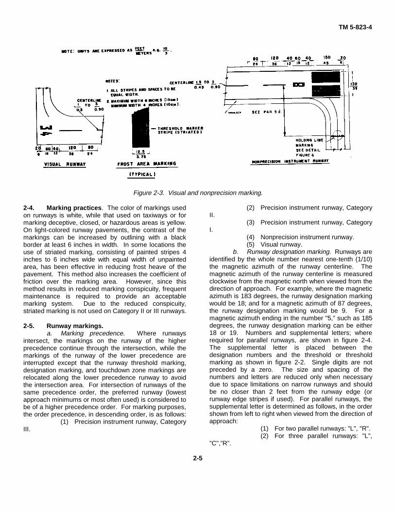
Figure 2-3. Visual and nonprecision marking.
2-4. Marking practices. The color of markings usedon runways is white, while that used on taxiways or formarking deceptive, closed, or hazardous areas is yellow.On light-colored runway pavements, the contrast of themarkings can be increased by outlining with a blackborder at least 6 inches in width. In some locations theuse of striated marking, consisting of painted stripes 4inches to 6 inches wide with equal width of unpaintedarea, has been effective in reducing frost heave of thepavement. This method also increases the coefficient offriction over the marking area. However, since thismethod results in reduced marking conspicuity, frequentmaintenance is required to provide an acceptablemarking system. Due to the reduced conspicuity,striated marking is not used on Category II or III runways.
2-5. Runway markings.a. Marking precedence. Where runways
intersect, the markings on the runway of the higherprecedence continue through the intersection, while themarkings of the runway of the lower precedence areinterrupted except that the runway threshold marking,designation marking, and touchdown zone markings arerelocated along the lower precedence runway to avoidthe intersection area. For intersection of runways of thesame precedence order, the preferred runway (lowestapproach minimums or most often used) is considered tobe of a higher precedence order. For marking purposes,the order precedence, in descending order, is as follows:
(1) Precision instrument runway, CategoryIII.
(2) Precision instrument runway, CategoryII.
(3) Precision instrument runway, CategoryI.
(4) Nonprecision instrument runway.(5) Visual runway.
b. Runway designation marking. Runways areidentified by the whole number nearest one-tenth (1/10)the magnetic azimuth of the runway centerline. Themagnetic azimuth of the runway centerline is measuredclockwise from the magnetic north when viewed from thedirection of approach. For example, where the magneticazimuth is 183 degrees, the runway designation markingwould be 18; and for a magnetic azimuth of 87 degrees,the runway designation marking would be 9. For amagnetic azimuth ending in the number "5," such as 185degrees, the runway designation marking can be either18 or 19. Numbers and supplemental letters; whererequired for parallel runways, are shown in figure 2-4.The supplemental letter is placed between thedesignation numbers and the threshold or thresholdmarking as shown in figure 2-2. Single digits are notpreceded by a zero. The size and spacing of thenumbers and letters are reduced only when necessarydue to space limitations on narrow runways and shouldbe no closer than 2 feet from the runway edge (orrunway edge stripes if used). For parallel runways, thesupplemental letter is determined as follows, in the ordershown from left to right when viewed from the direction ofapproach:
(1) For two parallel runways: "L", "R".(2) For three parallel runways: "L",
"C",”R”.
2-5

TM 5-823-4
Figure 2-4. Runway numbers and letters.
c. Runway threshold marking. The runwaythreshold marking consists of eight longitudinal stripes ofuniform dimensions arranged symmetrically about therunway centerline as shown in figure 2-2. The stripesare 150 feet long and 5 feet wide and are spaced 14inches apart except for the center space which is 8 feet.
d. Runway centerline markings. The runwaycenterline markings are located on the centerline of therunway and consist of a line of uniformly spaced stripesand gaps. The stripes are 120 feet in length, and thegaps are 80 feet in length as shown in figure 2-2.Adjustments to the length of the stripes and gaps, wherenecessary to accommodate the runway length, are madenear the runway midpoint. The minimum width of thestripes is 12 inches for visual runways, 18 inches fornonprecision instrument runways, and 36 inches forprecision instrument runways.
e. Runway touchdown zone marking.Touchdown zone markings consist of groups of one, two,and three rectangular bars symmetrically arranged inpairs about the runway centerline as shown in figure 2-2.For runways less than 150 feet in width, the markingsand spaces are reduced proportionally, but the lengthsremain the same. On shorter runways, those pairs ofmarkings which would extend to within 900 feet of therunway midpoint are eliminated. The
fixed distance markings are a part of the touchdownzone markings but are used alone on certainnonprecision instrument runways and visual runways asindicated in paragraphs 2-3a and 2-3b.
f. Runwayside stripe marking. Runway sidestripes consist of continuous stripes located along eachside of the runway to provide contrast with thesurrounding terrain or to delinate the full strength runwaypavement area. The maximum distance between theouter edges of the stripes is 200 feet. The stripes have aminimum width of 36 inches for precision instrumentrunways and are at least equal to the width of the runwaycenterline stripes on other runways.
g. Displaced threshold marking. Displacedthreshold areas which are used for takeoffs or rolloutsare marked as shown in figure 2-5a. Runway edgestripes, where used on the runway, are continued alongthe edges of the displaced threshold area. Taxiwaycenterline markings may extend into the displaced area.
h. Relocated threshold marking. Relocatedthreshold areas where the abandoned runway area is notused for taxiing are marked as shown in figure 2-5b andwhere used as a taxiway are marked as shown in figure2-5c.
i. Markings for blast pads and stopway.Markings for these areas are shown in figure 2-5b.
2-6

TM 5-823-4
Figure 2-5. Marking for displaced thresholds, blast pads and stopways.
2-7

TM 5-823-4
2-6. Taxiway markings.a. Taxiway centerline marking. The taxiway
centerline marking is a continuous yellow line of 6-inchminimum width.
(1) On a taxiway curve, the taxiwaycenterline marking continues from the straight portion ofthe taxiway at a constant distance from the outside edgeof the curve. For taxiway intersections designed for thestraight-through method of taxiing, the centerlinemarkings continue straight through the intersection.
(2) At taxiway intersections with a runwayend, the taxiway centerline marking is terminated at therunway edge (with exception of the situation where thereis a displaced threshold, in which case the taxiway
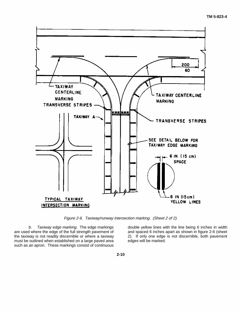
centerline may be extended onto the runway displacedarea). For intersections of taxiways with runways wherethe taxiway serves as an exit from the runway, thetaxiway centerline marking may be extended onto therunway as shown in figure 2-6. The taxiway centerlinemarking is extended parallel to the runway centerlinemarking for a distance of 200 feet beyond the point oftangency. The curve radius should be large enough toprovide a clearance to the taxiway or runway edge of atleast 1/2 the width of the taxiway. For taxiways crossinga runway, the taxiway centerline marking may continueacross the runway but must be interrupted for the runwaymarkings.
2-8

TM 5-823-4
Figure 2-6. Taxiway/runway intersection marking. (Sheet 1 of 2).
2-9
TM 5-823-4
Figure 2-6. Taxiway/runway intersection marking. (Sheet 2 of 2).
b. Taxiway edge marking. The edge markingsare used where the edge of the full strength pavement ofthe taxiway is not readily discernible or where a taxiwaymust be outlined when established on a large paved areasuch as an apron. These markings consist of continuous
double yellow lines with the line being 6 inches in widthand spaced 6 inches apart as shown in figure 2-6 (sheet2). If only one edge is not discernible, both pavementedges will be marked.
2-10

TM 5-823-4
Figure 2-7. Runway shoulder markings.
c. Holding position markings. Holding positionmarkings consist of a painted hold line and a Type 1 signas shown in figure 2-8. An unlighted Type 1 sign may beused on unlighted runways. The solid lines of theholding position markings are always on the side wherethe aircraft is to hold. The sign is installed on the leftside of the hold line as viewed from the holding side. Atlocations where it is impractical to install the sign on theleft side, it may be installed on the right side. For holdlines over 150 feet in length, signs are installed on both
sides. Where desired to increase the conspicuity of themarkings, reflective paint, reflective marking tape, or theaddition of in-pavement retroreflective markers may beused. The hold line markings are installed perpendicularto the taxiway centerline. Signs are installed inaccordance with AC 150/5340-18, Taxiway GuidanceSign System.
(1) Taxiway holding position markings.The taxiway holding line will be placed at a distance of100 feet from the structural pavement edge of a runway.
2-11

TM 5-823-4Where used, locate the taxiway holding line on taxiwayintersections 100 feet from the structural pavementedge. When the taxiway is associated with a holdingbay, the marking may be parallel to the centerline of therunway or intersecting taxiway. Details of the taxiwayholding line are shown in figures 2-2 and 2-6. Themarkings are not required on taxiways which are neverused for crossing or access to the runway. Theinscription on the associated sign is the runway number.For intersections where takeoffs are conducted, theinscription denotes only that particular runway such as"18." For other intersections, the inscription denotes bothrunways such as "18-36." In this example runway 18 is tothe left and runway 36 is to the right.
(2) ILS holding position markings. ILS(instrument landing system) holding position markings
are used to protect ILS localizer and glide slope criticalareas as shown in figure 2-8. Pending completion oftests and issuance of criteria for critical areas, the ILScritical areas should be used for microwave landingsystem (MLS) and interim standard MLS (ISMLS)facilities to insure signal protection. Where the normallocation of the ILS holding position marking and thetaxiway holding position marking falls within 25 feet ofeach other, the ILS holding position marking may beomitted provided that the taxiway holding positionmarking is located to protect both the runway and the ILScritical area. An ILS holding position marking shouldnever be installed between a taxiway holding positionmarking and a runway. The sign inscription for ILSholding position markings is "ILS."
2-12

TM 5-823-4
Figure 2-8. Holding position markings.
2-13

TM 5-823-4
2-7. Stabilized areas. Holding bays, aprons, andtaxiways are sometimes pr6vided with shoulderstabilization to prevent blast and water erosion. Thisstabilization may have the appearance of a full strengthpavement but is not intended for use by aircraft. Usuallythe taxiway edge marking will define this area, butconditions may exist such as stabilized islands or taxiwaycurves where confusion may exist as to which side of theedge stripe is the full strength pavement. Where such acondition exists, the stabilized area is marked with 3-footwide yellow lines perpendicular to the edge stripes asshown in figure 2-6 (sheet 2). On straight sections, themarks are placed at a maximum of 100-foot spacing. Oncurves, the marks are placed a maximum of 50 feetapart between the curve tangents. The stripes areextended to 5 feet from the edge of
the stabilized area or to 25 feet in length, whichever isless.
2-8. Runway shoulder marking. Usually therunway side stripes will indicate the edges of the fullstrength pavement. However, conditions may exist, suchas exceptionally wide runways, where there is a need toindicate the area not intended for use by aircraft. In suchcases, chevrons, as shown in figure 2-7, are used.
2-9. Aircraft parking ramps, tiedown and mooringareas. Tie-down points at parking ramps and tie-downor mooring areas are usually marked in the shape of aball with yellow nonreflective paint. Dimensions of thearea to be painted are at the discretion of the airfield orheliport commander.
2-14
TM 5-823-4CHAPTER 3
MARKING OR SERVICEABLE RUNWAYS AND TAXIWAYS AT HELIPORTS
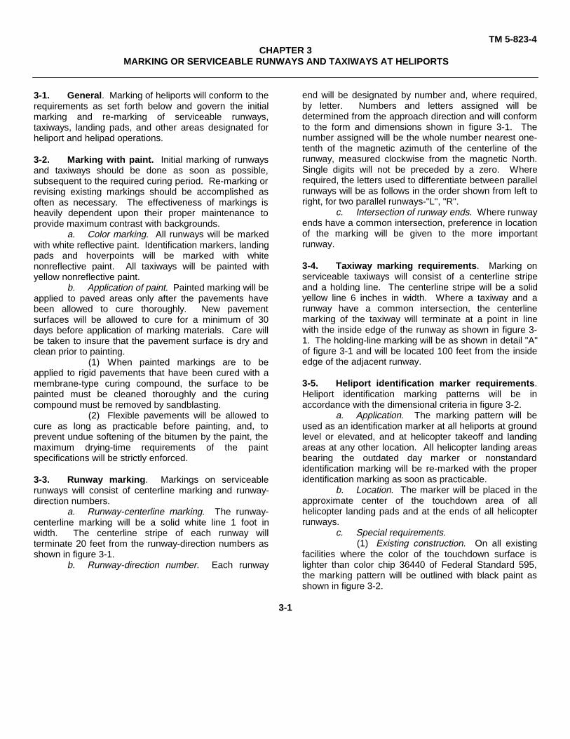
3-1. General. Marking of heliports will conform to therequirements as set forth below and govern the initialmarking and re-marking of serviceable runways,taxiways, landing pads, and other areas designated forheliport and helipad operations.
3-2. Marking with paint. Initial marking of runwaysand taxiways should be done as soon as possible,subsequent to the required curing period. Re-marking orrevising existing markings should be accomplished asoften as necessary. The effectiveness of markings isheavily dependent upon their proper maintenance toprovide maximum contrast with backgrounds.
a. Color marking. All runways will be markedwith white reflective paint. Identification markers, landingpads and hoverpoints will be marked with whitenonreflective paint. All taxiways will be painted withyellow nonreflective paint.
b. Application of paint. Painted marking will beapplied to paved areas only after the pavements havebeen allowed to cure thoroughly. New pavementsurfaces will be allowed to cure for a minimum of 30days before application of marking materials. Care willbe taken to insure that the pavement surface is dry andclean prior to painting.
(1) When painted markings are to beapplied to rigid pavements that have been cured with amembrane-type curing compound, the surface to bepainted must be cleaned thoroughly and the curingcompound must be removed by sandblasting.
(2) Flexible pavements will be allowed tocure as long as practicable before painting, and, toprevent undue softening of the bitumen by the paint, themaximum drying-time requirements of the paintspecifications will be strictly enforced.
3-3. Runway marking. Markings on serviceablerunways will consist of centerline marking and runway-direction numbers.
a. Runway-centerline marking. The runway-centerline marking will be a solid white line 1 foot inwidth. The centerline stripe of each runway willterminate 20 feet from the runway-direction numbers asshown in figure 3-1.
b. Runway-direction number. Each runway
end will be designated by number and, where required,by letter. Numbers and letters assigned will bedetermined from the approach direction and will conformto the form and dimensions shown in figure 3-1. Thenumber assigned will be the whole number nearest one-tenth of the magnetic azimuth of the centerline of therunway, measured clockwise from the magnetic North.Single digits will not be preceded by a zero. Whererequired, the letters used to differentiate between parallelrunways will be as follows in the order shown from left toright, for two parallel runways-"L", "R".
c. Intersection of runway ends. Where runwayends have a common intersection, preference in locationof the marking will be given to the more importantrunway.
3-4. Taxiway marking requirements. Marking onserviceable taxiways will consist of a centerline stripeand a holding line. The centerline stripe will be a solidyellow line 6 inches in width. Where a taxiway and arunway have a common intersection, the centerlinemarking of the taxiway will terminate at a point in linewith the inside edge of the runway as shown in figure 3-1. The holding-line marking will be as shown in detail "A"of figure 3-1 and will be located 100 feet from the insideedge of the adjacent runway.
3-5. Heliport identification marker requirements.Heliport identification marking patterns will be inaccordance with the dimensional criteria in figure 3-2.
a. Application. The marking pattern will beused as an identification marker at all heliports at groundlevel or elevated, and at helicopter takeoff and landingareas at any other location. All helicopter landing areasbearing the outdated day marker or nonstandardidentification marking will be re-marked with the properidentification marking as soon as practicable.
b. Location. The marker will be placed in theapproximate center of the touchdown area of allhelicopter landing pads and at the ends of all helicopterrunways.
c. Special requirements.(1) Existing construction. On all existing
facilities where the color of the touchdown surface islighter than color chip 36440 of Federal Standard 595,the marking pattern will be outlined with black paint asshown in figure 3-2.
3-1

TM 5-823-4
Figure 3-1. Guidelines for marking runways and taxiways at heliports.
The width of the pattern outline is referenced asdimension "D" in figure 3-2 and is the same for both theinner and outer outline. If the color of the touchdownarea is equal to or darker than the referenced color, theblack outline will not be included in the marking pattern.
(2) New construction. The touchdownarea on which the marking pattern will be placed will be
constructed in a manner so that the surface will be equalto or darker than color chip 36440 of Federal Standard595. The black pattern outline will not be included in themarking pattern. When the touchdown facility isconstructed of rigid pavement the referenced color willbe provided for a minimum thickness of 2 inches fromthe top surface.
3-2

TM 5-823-4
Figure 3-2. Helipad marking pattern.
3-3

TM 5-823-4CHAPTER 4
MARKING OF OVERRUN AND SHOULDER AREAS AT HELIPORTS
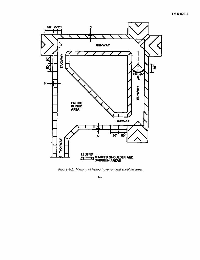
4-1. General. Double-bituminous-surface-treatmentoverrun and shoulder areas that are not intended foraircraft traffic will be marked with yellow lines 18 incheswide in accordance with the requirements below.Configurations complying with these requirements aredetailed in figures 4-1 and 4-2.
4-2. Overrun areas. Overrun areas will be markedwith a chevron layout as shown in figure 4-1. The indexpoint for the layout of the chevron marking will be thepoint of intersection of the runway centerline and therunway threshold line. The apex of the initial chevron onthe approach side of the threshold will be at a point 25feet outward from the index point. Subsequent chevronswill be placed on 50-foot centers as shown in figure 4-1.Partial chevrons will be placed as indicated in figure 4-1.The apex of each chevron will be on the centerline witheach leg making an angle of 45 degrees with the runwaycenterline. The chevrons will terminate at a point 5 feetinside the outer edge of the shoulder area.
4-3. Runway-shoulder areas. All runway-shoulderareas will be marked as shown in figure 4-1. Thesepartial chevrons are a continuation of the chevrons usedin marking overrun areas as indicated in paragraph 4-2above and as shown in figure 4-1. The chevrons used inmarking the runway-shoulder areas will have the sameindex point as the chevrons marking the overrun areas.Chevrons will be laid out uniformly from both ends of therunway as shown in figure 4-1. The partial chevrons willterminate at a point 5 feet inside the outer edge of theshoulder area.
4-4. Taxiway, taxilane, apron, hardstand, andengine-runup shoulder areas.
a. Straight sections. Straight sections oftaxiways will be marked by yellow lines 18 inches widebeginning at the runway-shoulder edge and spaced atintervals not exceeding 50 feet as shown in figure 4-1.The lines will be perpendicular to the centerline of the
taxiway, beginning at the edge of the taxiway andextending outward to a point 5 feet inside the outer edgeof the shoulder area. Straight sections of taxilane,apron, hardstand, and engine-runup shoulder areas willbe marked by lines beginning at points not exceeding 50feet from all points of tangency of curves and will beperpendicular to the paved area edges as shown infigures 4-1 and 4-2. Lines will terminate 5 feet inside theouter edge of the shoulder areas.
b. Curved sections. Curved sections of allshoulder areas will be marked by one line beginning atthe edge of the paved areas and extending outward to apoint 5 feet inside the outer edge of the shoulder area.The marking will be placed radially beginning at thecenter of the curve as shown in figures 4-1 and 4-2.
4-5. Detail requirements.a. Color marking. All heliport overrun and
shoulder areas will be marked with nonreflective yellowpaint.
b. Marking materials. Nonreflective paint usedin marking or re-marking overrun and shoulder areas willconsist of the pigmented binder (paint) stated inparagraph 2-2a(2) above.
c. Application of paint. Painted markings willbe applied to overrun and shoulder areas only after thedouble bituminous surface treatment has been allowedto cure as long as practicable. Care will be taken toinsure that the surface to be painted is clean and dryprior to painting. To prevent undue softening of thebitumen by the paint, the maximum drying-timerequirements of the paint specifications will be strictlyenforced.
4-1
TM 5-823-4
Figure 4-1. Marking of heliport overrun and shoulder area.
4-2

TM 5-823-4
Figure 4-2. Marking of shoulders for heliport parking and maintenance aprons and taxiways.
4-3

TM 5-823-4CHAPTER 5
MARKING AND LIGHTING OF CLOSED OR HAZARDOUS AREAS ON AIRFIELDS OR HELIPORTS
5-1. Permanently closed runways and taxiways.For runways and taxiways which have been permanentlyclosed, the lighting circuits will be disconnected. Forrunways, the threshold markings, runway designationmarking, and touchdown zone markings will beobliterated, and crosses will be placed at each end andat 1,000-foot intervals. For taxiways, a cross will beplaced on the closed taxiway at each entrance. Thecrosses shown in figures 5-1a and 5-1c are normallyused, but the crosses shown in figures 5-1b and 5-1d aremore readily seen from aircraft on final approach andmay be used where desired.
5-2. Temporarily closed runways and taxiways.Temporarily closed runways are treated in the samemanner as in paragraph 5-1 except runway and taxiwaylights will be turned off and runway markings are notobliterated, crosses are usually of the temporary type(constructed of material such as fabric or plywood), andcrosses are required only at runway ends. The crossesare located on top of the runway numerals. Fortemporary marking, the dimensions of the crossesshown in figures 5-1a and 5-1cmay be reduced to permituse of standard sheets of 4 by 8-foot plywood.Temporarily closed taxiways are usually treated as anunusable area as explained in paragraph 5-4 below.
5-3. Closed airfields and heliports. When allrunways are closed temporarily, the runways are markedas in paragraph 5-2 above and the airport beacon isturned off. When all runways are closed permanently,the runways are marked as in paragraph 5-1 above, theairport beacon is disconnected, and a cross is placed in
the segmented circle or at a central location if nosegmented circle exists.
5-4. Hazardous areas. Hazardous areas, in whichno part of an aircraft may enter, are indicated by use ofbarricades with alternate orange and white markings.The barricades are supplemented with orange flags aminimum of 20 by 20 inches square and made andinstalled so that they are always in the extended positionand properly oriented. For nighttime use the barricadesare supplemented with flashing red lights. The intensityof the lights and spacings for barricades, flags, and lightsmust be such to adequately define and delineate thehazardous area.
5-5. Stabilized areas. For marking requirements ofholding bays, aprons and taxiways of closed orhazardous areas at airfields and heliports, the criteriastated in paragraph 2-7 will apply.
5-6. Runway shoulder areas. For markingrequirements of runway shoulder areas of closed orhazardous areas at airfields and heliports, the criteriastated in paragraph 2-8 will apply.
5-1

TM 5-823-4
Figure 5-1. Closed runway and taxiway markings.
5-2

TM 5-823-4CHAPTER 6
MARKING OF COMPASS SWINGING BASES
6-1. General. Compass swinging bases for aliningaircraft for the precise calibration of all types of airnavigation equipment will be marked as shown in figurel1.
6-2. Magnetic effects. Because of the calibrationoperation involved, the compass-swinging base will belocated in an area of the airfield or heliport where localmagnetic influence is at a minimum to preclude inherentdeviations that would destroy the accuracy of thecalibration. To realize this objective, the compass-swinging base will not be placed in proximity to powertransmission lines or concentrations of undergroundconduits or pipe, railroads, or rail sidings, automobile oraircraft traffic, buildings containing ferrous metals, or inareas containing natural magnetic disturbances. Eachlocation for a compass-swinging base must be checkedby a magnetometer to insure that the area has negligiblemagnetic characteristics regardless of adherence to theabove criteria and magnetic limitations specified inMilitary Standard MIL-STD-765.
6-3. Pavement grade. The compass-swinging-basepad will be level in all directions. The grade of theconnecting taxiway and shoulder areas associated withthis facility will be in accordance with criteria given in TM58034.
6-4. Alinement markings. The compass-swinging-base pad will be marked with precision alinementindicators accurate to within 0.25 percent of 1 degree.
6-5. Clearances.
a. A minimum distance of 275 feet will beprovided from the center of the compass-swinging-basepad to the nearest: :
-Significant quantity of iron.-Parking area or hardstand for aircraft, vehicles,
or equipment.-Taxiway, or engine runup.b. A minimum distance of 100 feet will be
provided from the center of the compass-swinging baseto a 67 kilovolt or less power transmission line.Consideration will be given to the necessity for greaterseparation in order to avoid adverse influence frompower transmission lines in excess of 67 kilovolt.
6-6. Marking with paint. Initial marking and re-marking of compass swinging bases should be done assoon as possible, subsequent to the required curingperiod. Re-marking existing marks should beaccomplished as often as necessary. The effectivenessof markings is heavily dependent upon their propermaintenance to provide maximum contrast withbackgrounds. Compass-swinging bases will be paintedwith white nonreflective paint that conforms to paragraph2-2a(2).
6-7. Application of paint. For application of paintsee paragraph 2-2b.
6-1

TM 5-823-4
Figure 6-1. Army airfield-heliport compass swinging base.
para 4-5
EACH PROPOSED LOCATION FOR A COMPASS-SWINGING ABASE MUSTBE CHECKED BY A MAGNETOMETER TO INSURE THAT THE AREA HASNEGLIGIBLE MAGNETIC CHARACTERISTICS REGARDLESS OFADHERENCE TO PARA 4-5.
6-2

REPRODUCTION AUTHORIZATION/RESTRICTIONS
This manual has been prepared by or for the Government and is public property and notsubject to copyright. Reprints or republications of this manual should include a creditsubstantially as follows: "Department of the Army and Technical Manual TM 5-823-4,Marking of Army Airfield-Heliport Operational and Maintenance Facilities."
TM 5-823-4CHAPTER 7
MARKING OF OBSTRUCTIONS TO AIR NAVIGATION
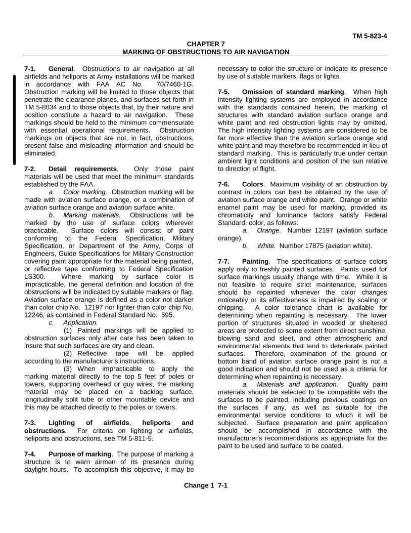
7-1. General. Obstructions to air navigation at allairfields and heliports at Army installations will be markedin accordance with FAA AC No. 70/7460-1G.Obstruction marking will be limited to those objects thatpenetrate the clearance planes, and surfaces set forth inTM 5-8034 and to those objects that, by their nature andposition constitute a hazard to air navigation. Thesemarkings should be held to the minimum commensuratewith essential operational requirements. Obstructionmarkings on objects that are not, in fact, obstructions,present false and misleading information and should beeliminated.
7-2. Detail requirements. Only those paintmaterials will be used that meet the minimum standardsestablished by the FAA.
a. Color marking. Obstruction marking will bemade with aviation surface orange, or a combination ofaviation surface orange and aviation surface white.
b. Marking materials. Obstructions will bemarked by the use of surface colors whereverpracticable. Surface colors will consist of paintconforming to the Federal Specification, MilitarySpecification, or Department of the Army, Corps ofEngineers, Guide Specifications for Military Constructioncovering paint appropriate for the material being painted,or reflective tape conforming to Federal SpecificationLS300. Where marking by surface color isimpracticable, the general definition and location of theobstructions will be indicated by suitable markers or flag.Aviation surface orange is defined as a color not darkerthan color chip No. 12197 nor lighter than color chip No.12246, as contained in Federal Standard No. 595.
c. Application.(1) Painted markings will be applied to
obstruction surfaces only after care has been taken toinsure that such surfaces are dry and clean.
(2) Reflective tape will be appliedaccording to the manufacturer’s instructions.
(3) When impracticable to apply themarking material directly to the top 5 feet of poles ortowers, supporting overhead or guy wires, the markingmaterial may be placed on a backlog surface,longitudinally split tube or other mountable device andthis may be attached directly to the poles or towers.
7-3. Lighting of airfields, heliports andobstructions. For criteria on lighting or airfields,heliports and obstructions, see TM 5-811-5.
7-4. Purpose of marking. The purpose of marking astructure is to warn airmen of its presence duringdaylight hours. To accomplish this objective, it may be
necessary to color the structure or indicate its presenceby use of suitable markers, flags or lights.
7-5. Omission of standard marking. When highintensity lighting systems are employed in accordancewith the standards contained herein, the marking ofstructures with standard aviation surface orange andwhite paint and red obstruction lights may by omitted.The high intensity lighting systems are considered to befar more effective than the aviation surface orange andwhite paint and may therefore be recommended in lieu ofstandard marking. This is particularly true under certainambient light conditions and position of the sun relativeto direction of flight.
7-6. Colors. Maximum visibility of an obstruction bycontrast in colors can best be obtained by the use ofaviation surface orange and white paint. Orange or whiteenamel paint may be used for marking, provided itschromaticity and luminance factors satisfy FederalStandard, color, as follows:
a. Orange. Number 12197 (aviation surfaceorange).
b. White. Number 17875 (aviation white).
7-7. Painting. The specifications of surface colorsapply only to freshly painted surfaces. Paints used forsurface markings usually change with time. While it isnot feasible to require strict maintenance, surfacesshould be repainted whenever the color changesnoticeably or its effectiveness is impaired by scaling orchipping. A color tolerance chart is available fordetermining when repainting is necessary. The lowerportion of structures situated in wooded or shelteredareas are protected to some extent from direct sunshine,blowing sand and sleet, and other atmospheric andenvironmental elements that tend to deteriorate paintedsurfaces. Therefore, examination of the ground orbottom band of aviation surface orange paint is not agood indication and should not be used as a criteria fordetermining when repainting is necessary.
a. Materials and application. Quality paintmaterials should be selected to be compatible with thesurfaces to be painted, including previous coatings onthe surfaces if any, as well as suitable for theenvironmental service conditions to which it will besubjected. Surface preparation and paint applicationshould be accomplished in accordance with themanufacturer’s recommendations as appropriate for thepaint to be used and surface to be coated.
Change 1 7-1
TM 5-823-4b. Surfaces not requiring paint. If the smooth
surface of paint on the ladders, decks and walkways ofcertain types of steel towers and similar structurespresents a potential danger to maintenance personnel,such surfaces need not be painted. Care should betaken so the overall marking effect of the painting is notreduced. Where the painting or the act of paintingcertain precision or critical surfaces would have anadverse effect on the desired transmission or radiationcharacteristics of a radio frequency signal, such paintingmay be omitted.
c. Skeletal structures. Paint should be appliedto all surfaces both ’inner and outer, of the framework inorder to be effective. This applies to the supportingstructures of overhead transmission lines as well asradio, television and similar skeletal structures.
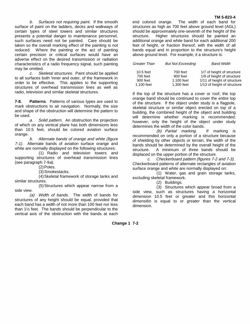
7-8. Patterns. Patterns of various types are used tomark obstructions to air navigation. Normally, the sizeand shape of the obstruction will determine the pattern tobe used.
a. Solid pattern. An obstruction the projectionof which on any vertical plane has both dimensions lessthan 10.5 feet, should be colored aviation surfaceorange.
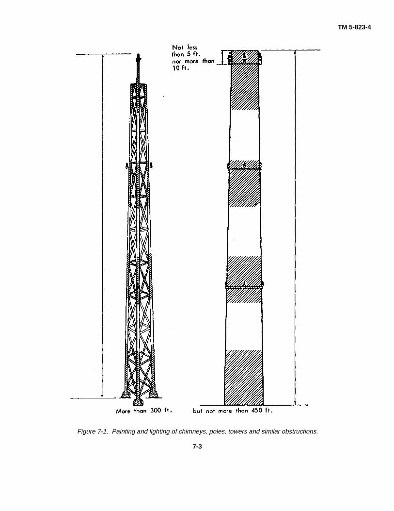
b. Alternate bands of orange and white (figure7-1). Alternate bands of aviation surface orange andwhite are normally displayed on the following structures:
(1) Radio and television towers andsupporting structures of overhead transmission lines(see paragraph 7-9a).
(2)Poles.(3)Smokestacks.(4)Skeletal framework of storage tanks and
similar structures.(5)Structures which appear narrow from a
side view.(a) Width of bands. The width of bands for
structures of any height should be equal, provided thateach band has a width of not more than 100 feet nor lessthan 1½ feet. The bands should be perpendicular to thevertical axis of the obstruction with the bands at each
end colored orange. The width of each band forstructures as high as 700 feet above ground level (AGL)should be approximately one-seventh of the height of thestructure. Higher structures should be painted anadditional orange and white band for each additional 200feet of height, or fraction thereof, with the width of allbands equal and in proportion to the structure's heightabove ground level. For example, it a structure is:
Greater Than But Not Exceeding Band Width
10.5 feet 700 feet 1/7 of height of structure700 feet 900 feet 1/9 of height of structure900 feet 1,100 feet 1/11 of height of structure
1,100 feet 1,300 feet 1/13 of height of structure
If the top of the structure has a cover or roof, the toporange band should be continued to cover the entire topof the structure. If the object under study is a flagpole,skeletal structure or similar object erected on top of abuilding, the combined height of the object and buildingwill determine whether marking is recommended;however, only the height of the object under studydetermines the width of the color bands.
(b) Partial marking. If marking isrecommended on only a portion of a structure becauseof shielding by other objects or terrain, the width of thebands should be determined by the overall height of thestructure. A minimum of three bands should bedisplaced on the upper portion of the structure.
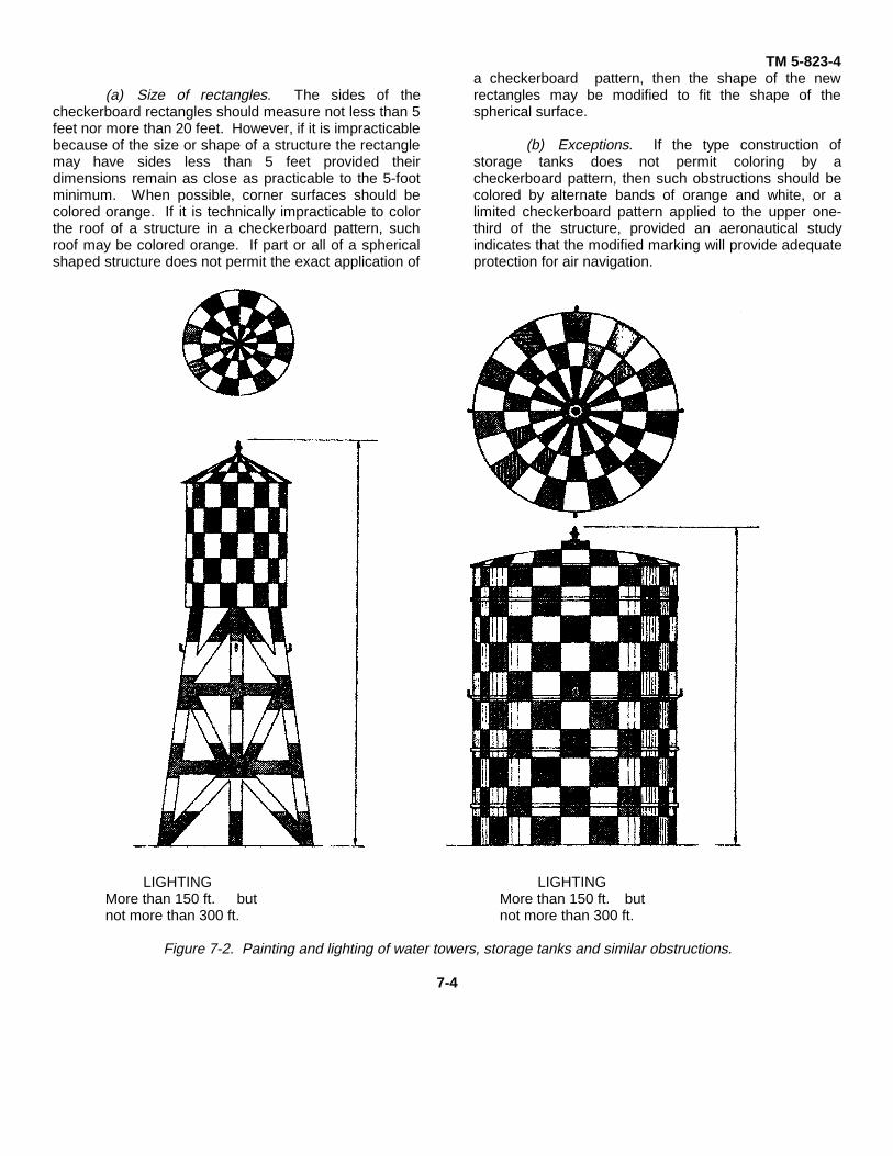
c. Checkerboard pattern (figures 7-2 and 7-3).Checkerboard patterns of alternate rectangles of aviationsurface orange and white are normally displayed on:
(1) Water, gas and grain storage tanks,excluding skeletal framework.
(2) Buildings.(3) Structures which appear broad from a
side view, such as structures having a horizontaldimension 10.5 feet or greater and this horizontaldimensi6n is equal to or greater than the verticaldimension.
Change 1 7-2
TM 5-823-4
Figure 7-1. Painting and lighting of chimneys, poles, towers and similar obstructions.
7-3
TM 5-823-4
(a) Size of rectangles. The sides of thecheckerboard rectangles should measure not less than 5feet nor more than 20 feet. However, if it is impracticablebecause of the size or shape of a structure the rectanglemay have sides less than 5 feet provided theirdimensions remain as close as practicable to the 5-footminimum. When possible, corner surfaces should becolored orange. If it is technically impracticable to colorthe roof of a structure in a checkerboard pattern, suchroof may be colored orange. If part or all of a sphericalshaped structure does not permit the exact application of
a checkerboard pattern, then the shape of the newrectangles may be modified to fit the shape of thespherical surface.
(b) Exceptions. If the type construction ofstorage tanks does not permit coloring by acheckerboard pattern, then such obstructions should becolored by alternate bands of orange and white, or alimited checkerboard pattern applied to the upper one-third of the structure, provided an aeronautical studyindicates that the modified marking will provide adequateprotection for air navigation.
LIGHTING LIGHTINGMore than 150 ft. but More than 150 ft. butnot more than 300 ft. not more than 300 ft.
Figure 7-2. Painting and lighting of water towers, storage tanks and similar obstructions.
7-4

TM 5-823-4
Figure 7-3. Painting and lighting of water towers and similar obstructions.
7-5
TM 5-823-4d. Teardrop pattern. Spherical shaped water
storage tanks with a single circular standpipe supportmay be colored in a teardrop stripped pattern, as shownin figure 7-4. The tank should be colored to showalternate stripes of aviation surface orange and white.The stripes should extend from the top center of the tankto its supporting standpipe.
(1) Width of stripes. The width of thestripes should be equal and the width of each stripe atthe greatest girth of the tank should not be less than 5feet nor more than 15 feet.
(2) Community name. If it is desirable topaint the name of the community on the side of the tank,the stripe pattern may be broken to serve this purpose.This open area should have a maximum height of 3 feet.
7-9. Markers. Markers should be used to markobstructions when it has been determined that it isimpracticable to mark such obstructions by painting.Markers may also be used in addition to aviation surfaceorange and white colors when it has been determinedthat such markings should be used to provide protectionfor air commerce. They should be displayed inconspicuous positions on or adjacent to the obstructionsso as to retain the general definition of the obstruction.They should be recognizable in clear air from a distanceof at least 1,000 feet in all directions from which anaircraft is likely to approach. They should be distinctivelyshaped so they are not mistaken for markers that areused to convey other information. The shape should besuch that the hazard they mark is not increased.
a. Spherical markers. Spherical markers arenormally displayed on overhead wires. Markers may beof another shape, provided the projected area of suchmarkers will not be less than that presented by aspherical marker.
(1) Display. At least one such markershould be displayed at equal intervals for each 150 feetor fraction thereof, of the overall length of the overheadline and not lower than the highest wire. The top 5 feetof the poles and towers to which overhead wires or guywires are attached will be marked. The distancebetween markers may be increased to not more than600 feet when the overhead wires are located more than15,000 feet from the nearest landing area. Where thereis more than one overhead wire on which the spherescan be installed, the spheres may be installed alternatelyalong each wire as long as the distance betweenadjacent spheres meets the spacing standard. This
allows the weight and wind loading factors to bedistributed.
(2) Size and color. The diameter of themarkers should not be less than 20 inches and should becolored aviation orange.
b. Flag markers. Flags may be used to markobstructions when it has been determined that the use ofcoloring or spherical markers is technically impracticable.
(1) Display. Flag markers should bedisplayed around, on top of the obstruction or around itshighest edge. When flags are used to mark extensiveobstructions or closely grouped obstructions, they shouldbe displayed approximately 50 feet apart.
(2) Shape. Flags should be rectangular inshape and have stiffeners to keep them from drooping incalm wind. The flag stakes should be of such strengthand height that they will support the flags free of theground, vegetation or nearby surfaces.
(3) Color patterns. Flags should be in oneof the following patterns:
(a) Solid color. Aviation surfaceorange not less than 2 feet on a side.
(b) Orange and white. Two triangularsections, one of aviation surface orange and the other ofaviation surface white, combined to form a rectangle notless than 2 feet on a side.
(c) Checkerboard. A checkerboardpattern of aviation surface orange and aviation surfacewhite squares, each 1 foot plus or minus 10 percent on aside, combined to form a rectangle not less than 3 feeton a side.
7-10. Special markings. In addition to the markingrecommendations included herein other documentscontain appropriate guidelines.
a. Vehicles. Advisory Circular 150/5210-5,Painting, Marking and Lighting of Vehicles Used on anAirport, contains provisions for marking vehiclescustomarily used on landing areas.
b. FAA facilities. Obstruction marking for FAAfacilities shall conform to FAA Drawing Number D-5480,referenced in Federal Aviation Agency Standard, FAA-STD-003, Paint Systems for Structures.
c. Unusual complexities. The FAA may alsorecommend appropriate marking in an area whereobstructions are so grouped as to present a commonhazard to air commerce.
7-6

Figure 7-4. Painting of single pedestal water tower by teardrop pattern.
7-7

TM 5-823-4CHAPTER 8
GROUND RECEIVER CHECKPOINTS
8-1. Location. Ground receiver checkpoints will beestablished in accordance with FAA Order 6790.4A andwill be on the airfield or heliport ramp or taxiways(preferably the runup area) at points selected for easyaccess by aircraft, but where other airfield or heliporttraffic will not be unduly obstructed.
Ground checkpoints normally will not be established atdistances less than one-half mile from the facility norshould they be established on non-paved areas.
8-2. Markings. Painting of surface markings will beas described in figure 8-1 below.
Figure 8-1. Ground receiver checkpoint markings.
Change 1 8-1

TM 5-823-4APPENDIX A
REFERENCES
Government Publications
Department of DefenseMIL-STD-765 General Requirements for Compass Swinging, Aircraft
Department of the ArmyTM 5-8034 Planning of Army Aviation Facilities
TM 5811-5 Army Aviation Lighting
Department of TransportationFederal Aviation Administration (FAA), Superintendent of Documents, U.S. Government Printing Office,Washington, DC 20402
AC No. 70/7460-1G Obstruction Marking and Lighting
AC No. 150/5210-5 Painting, Marking and Lighting of Vehicles Used on Airports
AC No. 150/5340-1E Marking of Paved Areas on Airports
AC No. 150/5340-18 Taxiway Guidance Sign System
FAA Order 6790.4A Maintenance of VHF Equipment
FAA-STD-003 Paint Systems for Structures
Government Services AdministrationFederal Standards (Fed. Std.), Superintendent of Documents, U.S. Government Printing Office,
Washington, DC 20402
Fed. Std. 595 Color Guide, Ready Mixed Paint
Federal Specifications (Fed. Spec.), Superintendent of Documents, U.S. Government PrintingOffice, Washington, DC 20402
Fed. Spec. L-S-300 Sheeting and Tape, Reflective
Fed. Spec. TT-B-1325 Beads (Glass Spheres), Retro-Reflective
Fed. Spec. TT-P-85E Paint, Traffic and Airfield Marking, Solvent Base
Fed. Spec. TT-P-1952 Paint, Traffic and Airfield Marking, Emulsion Base
Change 1 A-1

TM 5-823-4
The proponent agency of this publication is the Office of the Chief of Engineers, United States Army. Users areinvited to send comments and suggested improvements on DA Form 2028 (Recommended Changes toPublications and Blank Forms) direct to HQDA (DAEN-ECE-G), WASH DC 20314-1000.
By Order of the Secretary of the Army:
Carl E. VuonoGeneral, United States Army
Official: Chief of Staff
R. L. DILWORTHBrigadier General, United States Army
The Adjutant General
DISTRIBUTION:To be distributed in accordance with DA Form 12-34B, requirements for Airfield Pavements.
* U.S. GOVERNMENT PRINTING OFFICE : 1993 O - 342-421 (80004)

PIN: 025951-000