asce 41-17 tier 1 seismic evaluation · 2020-01-01 · “1997 preliminary seismic evaluation...
TRANSCRIPT

Evaluator: TAB
Date: 02/19/19
ASCE 41-17 Tier 1 Seismic Evaluation
Building Name: Beverly Cleary Hall South
CAAN ID: 1002
Auxiliary Building ID: N/A
Address: 2424 Channing Way, Berkeley, CA
Site location coordinates: Latitude 37.8664 Longitudinal -122.2595
Aerial Photo West Elevation Above Podium
UCOP SEISMIC PERFORMANCE LEVEL (OR “RATING”) BASED ON TIER 1 EVALUATION FINDINGS: IV
BUILDING DATA
ASCE 41-17 Model Building Type (Governing Building Type bolded for Seismic Risk Model when multiple
types exist):
a. Longitudinal Direction: W1A: Wood Light Frame, over C2: Conc. SW and RM2: Masonry SW
b. Transverse Direction: W1A: Wood Light Frame, over C2: Conc. SW and RM2: Masonry SW
Square Footage: 32,774 ft2 (Includes BSMT) out of 58,668 ft2 total
Building Length: 246’ – 4”
Building Width: 107’ – 8”
Building Height: 57’-4 ½” (to roof ridgeline)
Story Height: 11’-3” (1st), 9’–2 ½” (2nd-4th), 9’ (5th)
Number of stories above grade: 4
Number of basement stories below grade: 1 podium level, partially below grade
Year of Original Construction and Code Year: 1992, 1988 UBC
Year of Later Constuction and Code Year: N/A
Page 1

Building Name: Beverly Cleary Hall South Evaluator: TAB
CAAN ID: 1002 Date: 02/19/19
COST RANGE TO RETROFIT (if applicable): N/A
BUILDING DESCRIPTION
General
This building completed construction in 1992 and is situated on a North to South sloping site. The
building has four liveable stories with an attic space above and one partially below grade podium level.
The total structure height is approximately 57 feet tall. The building is rectangular in shape with a
footprint of about 246 feet in the NS direction and 108 feet in the EW direction. The building area is
approximately 37,300 square feet and is used as residential housing with parking in the podium level.
Structural System
The structure is a concrete/masonry podium structure with timber framing above. The typical gravity
structural system above the podium consists of plywood deck over engineered timber joists supported
by stud bearing walls. The floors have a 1” thick Gypcrete topping slab. The first floor is a reinforced
two-way concrete slab supported by concrete and masonry walls with secondary concrete columns all
founded on spread footings. The lateral system above the podium consists of horziontal plywood
diaphragms and vertical plywood shear walls. The podium portion of the structure utilize a +12” thick
concrete diaphragm at the ground level to transfer lateral forces to masonry and concrete shear walls
along the perimeter of the garage level.
Building Condition
Good, building manager indicated water damage in the community bathroom locations
Date of Site Visit: 02/15/2019, Ray Pugliesi & Torrey Bolden, Degenkolb Engineers
Limitations of walk-through: none
SITE INFORMATION
Site Class (A-F): D Basis: Default per ASCE41-17
Site Specific Ground Motion Study? No
BSE-1N Spectral Accelerations: Basis: https://seismicmaps.org/
SDS: 1.606 SD1: 1.003
BSE-2E Spectral Accelerations: Basis: https://seismicmaps.org/
SXS: 2.412 SX1: 1.368
Level of Seismicity: High
Performance Level: Collapse Prevention Structural Performance
Geologic Hazards:
Fault Rupture No Basis: Earthquake Zones of Required Investigation- Oakland West Quadrangle
https://maps.conservation.ca.gov/cgs/informationwarehouse/regulatorymaps/
Liquefaction No Basis: Earthquake Zones of Required Investigation- Oakland West Quadrangle
https://maps.conservation.ca.gov/cgs/informationwarehouse/regulatorymaps/
Landslide No Basis: Earthquake Zones of Required Investigation- Oakland West Quadrangle
https://maps.conservation.ca.gov/cgs/informationwarehouse/regulatorymaps/
Page 2

Building Name: Beverly Cleary Hall South Evaluator: TAB
CAAN ID: 1002 Date: 02/19/19
PREVIOUS RATINGS SUMMARY
1. Good – 1997 Preliminary Seismic Evaluation (SAFER), Rutherford & Chekene
2. Fair – 10/26/07 - , Interactive Resources , “Preliminary Seismic Assessment (ASCE 31-03
Evaluation) of Beverly Cleary Hall”
DOCUMENTATION
Architectural Drawings: Haste/Channing Student Housing & Parking, Cygna Engineers, Tai
Associates/Architects, 5/10/91, A0.0-A9.9
Structural Drawings: Haste/Channing Student Housing & Parking, Cygna Engineers, 5/10/91,
S0.0-S4.3
Seismic Evaluations:
“1997 Preliminary Seismic Evaluation (SAFER)”, Rutherford & Chekene, 07/17/97, Tier 1
“Preliminary Seismic Assessment (ASCE 31-03 Evaluation) of Beverly Cleary Hall located at 2525
Channing, Berkeley, CA IR 2007-044-01”, Donald A Cushing Jr., 10/26/07, ASCE 31-03 Tier 1 with
Limited Tier 2
Geotechnical Reports: N/A
Other Documents: N/A
LATERAL-FORCE-RESISTING SYSTEM
Longitudinal Transverse
ASCE 41-17 Building Type: W1A: Wood Light Frames W1A: Wood Light Frames
Diaphragms: Plywood w/ 1” Gyp Topping Plywood w/ 1” Gyp Topping
Vertical Elements: Plywood Stud Shear Walls Plywood Stud Shear Walls
Connections: Nailing, Sill Bolts, HDs Nailing, Sill Bolts, HDs
Details: 9/S0.2 Wall Sheathing
5/S0.2 Diaphragm Sheathing
9/S0.2 Wall Sheathing
5/S0.2 Diaphragm Sheathing
Estimated Fundamental Period, T (sec): 0.363 0.363
BSE-2E Spectral Acceleration, Sa: 2.41g 2.41g
CONSTRUCTION DATA
Gravity Load Structural System: Plywood sheathing on timber joists supported by stud bearing walls
Exterior Transverse Walls: Plywood Sheathing w/ Plaster Opening(s)? Yes
Exterior Longitudinal Walls: Plywood Sheathing w/ Plaster Opening(s)? Yes
Roof Materials/Framing: Composition Shingles over ½” Plywood on 2x12 Rafters
Intermediate Floors/Framing: 1” Gypcrete over ¾” Plywood on TJI25 Typ.
Ground Floor: 12” – 15” Concrete Slab
Columns: N/A Foundation: Spread footings
General Condition of Structure: Good
Evidence of Settling? : No
Special Features & Comments: This structure is on top of a CMU/concrete podium. The podium
level to the North of the site is completely below grade and slopes
to the south so that south elevation is completely above grade
Page 3

Building Name: Beverly Cleary Hall South Evaluator: TAB
CAAN ID: 1002 Date: 02/19/19
Modification Factor, C: 1.0 (W1A – Table 4-7) 1.0 (W1A – Table 4-7)
Building Weight, W (kips): 789 789
Seismic Base Shear, V (kips): 1,902 1,902
System Modification Factor, Ms: 4.5 for wood framing at CP
per TBL 4-8
4.5 for wood framing at CP
per TBL 4-8
Significant Structural Deficiencies, Potentially Affecting Seismic Performance Level Designation:
Lateral System Stress Check (wall shear, column shear or flexure, or brace axial as applicable)
Load Path
Adjacent Buildings
☐ Weak Story
☐ Soft Story
☐ Geometry (vertical irregularities)
☐ Torsion
Mass – Vertical Irregularity
☐ Cripple Walls
☐ Wood Sills (bolting)
☐ Diaphragm Continuity
☐ Openings at Shear Walls (concrete or masonry)
☐ Liquefaction
☐ Slope Failure
☐ Surface Fault Rupture
☐ Masonry or Concrete Wall Anchorage at Flexible Diaphragm
☐ URM wall height to thickness ratio
☐ URM Parapets or Cornices
☐ URM Chimney
☐ Heavy Partitions Braced by Ceilings
☐ Appendages
OVERALL SEISMIC DEFICIENCIES & EXPECTED SEISMIC PERFORMANCE
The below items have been identified as non-compliant:
1. Walls connected through floors: various locations at the second floor do not call for hold-downs
where there are hold downs specified at the stories above and below. At these locations the
Page 4

Building Name: Beverly Cleary Hall South Evaluator: TAB
CAAN ID: 1002 Date: 02/19/19
walls lack flexural continuity up the height of the building. If the hold downs are not present
there is potential for increased deformations and damage at the walls toe due to unrestrained
uplift.
2. CMU Shear Wall Stress Check: In the east west direction loading of the building both CMU and
Concrete walls are utilized to resist seismic forces in the podium level. The average shear stress
of the wall is 119 psi which is greater than the 70 psi prescribed by the quick check procedure.
When the CMU wall contribution is taken from the base shear and the remaining concrete wall
is evaluated the wall stress is less than the 2√f’ce and greater than 2√f’c.The inadequacy of the
CMU wall in the lateral system is not believed to be a hazard to the overall stability of the
system, as the concrete wall can support the resulting shear demand.
3. Wood Shear Wall Stress Check: The shear stresses in the walls at the first timber framing story
are slightly over the allowable stress value of 1000 plf. This overstressing of the shear walls
would result in increased damage to the wall finish, but is not expected to be considerable life-
safety hazard.
4. Adjacent Buildings: The timber structures atop the podium are structurally separated by a 4”
seismic gap between the North and South superstructures and 2” between the North and
multipurpose structure. These gap dimensions are insufficient to preclude pounding during an
intense seismic event. These structures benefit from the floor levels aligning with the adjacent
structure, which is expected to mitigate structural damage. This deficiency is not considered to
be a life-safety issue.
5. Discontinuous roof chord: The roof lacks sub-chords where dormers interrupt the diaphragm.
The dormers are typical located next the transverse walls, and is not considered to be a
diaphragm flaw.
The lateral system of the South portion of the Beverly Cleary Residence Hall has a high level of
redundancy, and therefore likely capable of spreading the damage during a large seismic event. The lack
of the wall hold-downs at the second floor and the slight overstressing of the wall is not expected to be
a life safety hazard. The walls are expected to rock at the second floor, and experience increased
damage at the lower floors but not develop a structural instability. The pounding hazard is not expected
to affect the structural response as the floors align at each level. In the podium level, the concrete shear
walls are capable of compensating for the CMU walls that do not meet the criteria for the quick check
procedures. For these reasons, the deficiencies are not expected to cause a life safety hazard and this
structure has been assigned a SPL rating of IV. This was concurred by the peer review group comprising
of Rutherford + Chekene, Degenkolb Engineers, and Forell/Elsesser Engineers on February, 28, 2019.
The building manager indicated there has been on-going plumbing issues in the community restrooms. A
portion of the bathroom was exposed during the site visit and did not appear to have any significant
structural deterioration due to the related plumbing issues. This is not believed to be structural issue at
this time.
Page 5

Building Name: Beverly Cleary Hall South Evaluator: TAB
CAAN ID: 1002 Date: 02/19/19
Appendices
A. Additional Photos
B. ASCE 41-17 Tier 1 Checklists (Structural)
C. UCOP Seismic Safety Policy Falling Hazards Assessment Summary
D. Quick Check Calculations
Page 6

Building Name: Beverly Cleary Hall South Evaluator: TAB
CAAN ID: 1002 Date: 02/19/19
APPENDIX A
Additional Photos
Exposed Plywood Shear Wall in Community Bathroom, 3rd Floor
Seismic Joint, North Elevation
Page 7

Building Name: Beverly Cleary Hall South Evaluator: TAB
CAAN ID: 1002 Date: 02/19/19
Typical Residence Hall Corridor
Page 8

Building Name: Beverly Cleary Hall South Evaluator: TAB
CAAN ID: 1002 Date: 02/19/19
APPENDIX B
ASCE 41-17 Tier 1 Checklist (Structural)
Page 9

UC Campus: Berkeley Date: 2/20/2019
Building CAAN: 1002 Auxiliary CAAN:
1002.0 By Firm: Degenkolb Engineers
Building Name: Cleary Hall South Initials: TAB Checked:
Building Address: 2424 Channing Way, Berkeley, CA Page: 1 of 3
ASCE 41-17
Collapse Prevention Basic Configuration Checklist
Note: C = Compliant NC = Noncompliant N/A = Not Applicable U = Unknown
LOW SEISMICITY
BUILDING SYSTEMS - GENERAL
Description
C NC N/A U
LOAD PATH: The structure contains a complete, well-defined load path, including structural elements and connections, that
serves to transfer the inertial forces associated with the mass of all elements of the building to the foundation. (Commentary:
Sec. A.2.1.1. Tier 2: Sec. 5.4.1.1)
Comments: The structural drawings are missing hold-downs at the second timber framing level. The lack of hold downs is a lapse in the load path of the structure.
C NC N/A U
ADJACENT BUILDINGS: The clear distance between the building being evaluated and any adjacent building is greater than
0.25% of the height of the shorter building in low seismicity, 0.5% in moderate seismicity, and 1.5% in high seismicity.
(Commentary: Sec. A.2.1.2. Tier 2: Sec. 5.4.1.2)
Comments: The seismic gap between structures is inadequate at the upper stories.
C NC N/A U
MEZZANINES: Interior mezzanine levels are braced independently from the main structure or are anchored to the seismic-
force-resisting elements of the main structure. (Commentary: Sec. A.2.1.3. Tier 2: Sec. 5.4.1.3)
Comments:
BUILDING SYSTEMS - BUILDING CONFIGURATION
Description
C NC N/A U
WEAK STORY: The sum of the shear strengths of the seismic-force-resisting system in any story in each direction is not
less than 80% of the strength in the adjacent story above. (Commentary: Sec. A2.2.2. Tier 2: Sec. 5.4.2.1)
Comments:
C NC N/A U
SOFT STORY: The stiffness of the seismic-force-resisting system in any story is not less than 70% of the seismic-force-
resisting system stiffness in an adjacent story above or less than 80% of the average seismic-force-resisting system stiffness
of the three stories above. (Commentary: Sec. A.2.2.3. Tier 2: Sec. 5.4.2.2)
Comments:
C NC N/A U
VERTICAL IRREGULARITIES: All vertical elements in the seismic-force-resisting system are continuous to the foundation.
(Commentary: Sec. A.2.2.4. Tier 2: Sec. 5.4.2.3)
Comments: Structure is regular on top of the podium. Change is SFRS dimensions at the podium level.
Page 10

UC Campus: Berkeley Date: 2/20/2019
Building CAAN: 1002 Auxiliary CAAN:
1002.0 By Firm: Degenkolb Engineers
Building Name: Cleary Hall South Initials: TAB Checked:
Building Address: 2424 Channing Way, Berkeley, CA Page: 2 of 3
ASCE 41-17
Collapse Prevention Basic Configuration Checklist
Note: C = Compliant NC = Noncompliant N/A = Not Applicable U = Unknown
C NC N/A U
GEOMETRY: There are no changes in the net horizontal dimension of the seismic-force-resisting system of more than 30%
in a story relative to adjacent stories, excluding one-story penthouses and mezzanines. (Commentary: Sec. A.2.2.5. Tier 2:
Sec. 5.4.2.4)
Comments: Structure is regular on top of the podium. Change is SFRS dimensions >30% at the podium level.
C NC N/A U
MASS: There is no change in effective mass of more than 50% from one story to the next. Light roofs, penthouses, and
mezzanines need not be considered. (Commentary: Sec. A.2.2.6. Tier 2: Sec. 5.4.2.5)
Comments: The structure is regular above the podium level. Change is mass at the podium level relative to superstructure level
C NC N/A U
TORSION: The estimated distance between the story center of mass and the story center of rigidity is less than 20% of
the building width in either plan dimension. (Commentary: Sec. A.2.2.7. Tier 2: Sec. 5.4.2.6)
Comments:
MODERATE SEISMICITY (COMPLETE THE FOLLOWING ITEMS IN ADDITION TO THE ITEMS FOR LOW SEISMICITY)
GEOLOGIC SITE HAZARD
Description
C NC N/A U
LIQUEFACTION: Liquefaction-susceptible, saturated, loose granular soils that could jeopardize the building’s seismic
performance do not exist in the foundation soils at depths within 50 ft (15.2m) under the building. (Commentary: Sec. A.6.1.1.
Tier 2: 5.4.3.1)
Comments:
C NC N/A U
SLOPE FAILURE: The building site is located away from potential earthquake-induced slope failures or rockfalls so that it is unaffected by such failures or is capable of accommodating any predicted movements without failure. (Commentary: Sec. A.6.1.2. Tier 2: 5.4.3.1)
Comments:
C NC N/A U
SURFACE FAULT RUPTURE: Surface fault rupture and surface displacement at the building site are not anticipated.
(Commentary: Sec. A.6.1.3. Tier 2: 5.4.3.1)
Comments:
Page 11

UC Campus: Berkeley Date: 2/20/2019
Building CAAN: 1002 Auxiliary CAAN:
1002.0 By Firm: Degenkolb Engineers
Building Name: Cleary Hall South Initials: TAB Checked:
Building Address: 2424 Channing Way, Berkeley, CA Page: 3 of 3
ASCE 41-17
Collapse Prevention Basic Configuration Checklist
Note: C = Compliant NC = Noncompliant N/A = Not Applicable U = Unknown
HIGH SEISMICITY (COMPLETE THE FOLLOWING ITEMS IN ADDITION TO THE ITEMS FOR MODERATE SEISMICITY)
FOUNDATION CONFIGURATION
Description
C NC N/A U
OVERTURNING: The ratio of the least horizontal dimension of the seismic-force-resisting system at the foundation level to the building height (base/height) is greater than 0.6Sa. (Commentary: Sec. A.6.2.1. Tier 2: Sec. 5.4.3.3)
Comments:
C NC N/A U
TIES BETWEEN FOUNDATION ELEMENTS: The foundation has ties adequate to resist seismic forces where footings, piles, and piers are not restrained by beams, slabs, or soils classified as Site Class A, B, or C. (Commentary: Sec. A.6.2.2. Tier 2: Sec. 5.4.3.4)
Comments: Spread footings tied together with 6” slab on grade.
Page 12

UC Campus: Berkeley Date: 2/19/2019
Building CAAN: 1002 Auxiliary CAAN:
1002.0 By Firm: Degenkolb Engineers
Building Name: Cleary Hall South Initials: TAB Checked:
Building Address: 2424 Channing Way, Berkeley, CA Page: 1 of 4
ASCE 41-17
Collapse Prevention Structural Checklist For Building Type W1-W1A
Note: C = Compliant NC = Noncompliant N/A = Not Applicable U = Unknown
LOW AND MODERATE SEISMICITY
SEISMIC-FORCE-RESISTING SYSTEM
Description
C NC N/A U
REDUNDANCY: The number of lines of shear walls in each principal direction is greater than or equal to 2. (Commentary: Sec. A.3.2.1.1. Tier 2: Sec. 5.5.1.1)
Comments:
C NC N/A U
SHEAR STRESS CHECK: The shear stress in the shear walls, calculated using the Quick Check procedure of Section 4.4.3.3, is less than the following values: (Commentary: Sec. A.3.2.7.1. Tier 2: Sec. 5.5.3.1.1)
Structural panel sheathing 1,000 lb/ft (14.6 kN/m)
Diagonal sheathing 700 lb/ft (10.2 kN/m)
Straight sheathing 100 lb/ft (1.5 kN/m)
All other conditions 100 lb/ft (1.5 kN/m)
Comments: Maximum Stress > 1000 plf. See Quick Checks
C NC N/A U
STUCCO (EXTERIOR PLASTER) SHEAR WALLS: Multi-story buildings do not rely on exterior stucco walls as the primary seismic-force-resisting system. (Commentary: Sec. A.3.2.7.2. Tier 2: Sec. 5.5.3.6.1)
Comments:
C NC N/A U
GYPSUM WALLBOARD OR PLASTER SHEAR WALLS: Interior plaster or gypsum wallboard is not used for shear walls on buildings more than one story high with the exception of the uppermost level of a multi-story building. (Commentary: Sec. A.3.2.7.3. Tier 2: Sec. 5.5.3.6.1)
Comments:
C NC N/A U
NARROW WOOD SHEAR WALLS: Narrow wood shear walls with an aspect ratio greater than 2-to-1 are not used to resist seismic forces. (Commentary: Sec. A.3.2.7.4. Tier 2: Sec. 5.5.3.6.1)
Comments:
Page 13

UC Campus: Berkeley Date: 2/19/2019
Building CAAN: 1002 Auxiliary CAAN:
1002.0 By Firm: Degenkolb Engineers
Building Name: Cleary Hall South Initials: TAB Checked:
Building Address: 2424 Channing Way, Berkeley, CA Page: 2 of 4
ASCE 41-17
Collapse Prevention Structural Checklist For Building Type W1-W1A
Note: C = Compliant NC = Noncompliant N/A = Not Applicable U = Unknown
C NC N/A U
WALLS CONNECTED THROUGH FLOORS: Shear walls have an interconnection between stories to transfer overturning and shear forces through the floor. (Commentary: Sec. A.3.2.7.5. Tier 2: Sec. 5.5.3.6.2)
Comments: Various locations at the 2nd floor do not have a hold down specified when there is a hold down specified on the stories above and below.
C NC N/A U
HILLSIDE SITE: For structures that are taller on at least one side by more than one-half story because of a sloping site, all shear walls on the downhill slope have an aspect ratio less than 1-to-1. (Commentary: Sec. A.3.2.7.6. Tier 2: Sec. 5.5.3.6.3)
Comments:
C NC N/A U
CRIPPLE WALLS: Cripple walls below first-floor-level shear walls are braced to the foundation with wood structural panels. (Commentary: Sec. A.3.2.7.7. Tier 2: Sec. 5.5.3.6.4)
Comments:
C NC N/A U
OPENINGS: Walls with openings greater than 80% of the length are braced with wood structural panel shear walls with aspect ratios of not more than 1.5-to-1 or are supported by adjacent construction through positive ties capable of transferring the seismic forces. (Commentary: Sec. A.3.2.7.8. Tier 2: Sec. 5.5.3.6.5)
Comments:
CONNECTIONS
Description
C NC N/A U
WOOD POSTS: There is a positive connection of wood posts to the foundation. (Commentary: Sec. A.5.3.3. Tier 2: Sec. 5.7.3.3)
Comments: Detail 2/S0.5
C NC N/A U
WOOD SILLS: All wood sills are bolted to the foundation. (Commentary: Sec. A.5.3.4. Tier 2: Sec. 5.7.3.3)
Comments: Detail 2/S0.2
C NC N/A U
GIRDER-COLUMN CONNECTION: There is a positive connection using plates, connection hardware, or straps between the girder and the column support. (Commentary: Sec. A.5.4.1. Tier 2: Sec. 5.7.4.1)
Comments: Steel beam to wood post detail 10/S4.2. Typical framing is TJI joists between load bearing walls
Page 14

UC Campus: Berkeley Date: 2/19/2019
Building CAAN: 1002 Auxiliary CAAN:
1002.0 By Firm: Degenkolb Engineers
Building Name: Cleary Hall South Initials: TAB Checked:
Building Address: 2424 Channing Way, Berkeley, CA Page: 3 of 4
ASCE 41-17
Collapse Prevention Structural Checklist For Building Type W1-W1A
Note: C = Compliant NC = Noncompliant N/A = Not Applicable U = Unknown
HIGH SEISMICITY (COMPLETE THE FOLLOWING ITEMS IN ADDITION TO THE ITEMS FOR LOW AND MODERATE SEISMICITY)
CONNECTIONS
Description
C NC N/A U
WOOD SILL BOLTS: Sill bolts are spaced at 6 ft or less with acceptable edge and end distance provided for wood and concrete. (Commentary: Sec. A.5.3.7. Tier 2: Sec. 5.7.3.3)
Comments: Detail 2/S0.2
DIAPHRAGMS
Description
C NC N/A U
DIAPHRAGM CONTINUITY: The diaphragms are not composed of split-level floors and do not have expansion joints. (Commentary: Sec. A.4.1.1. Tier 2: Sec. 5.6.1.1)
Comments
C NC N/A U
ROOF CHORD CONTINUITY: All chord elements are continuous, regardless of changes in roof elevation. (Commentary: Sec. A.4.1.3. Tier 2: Sec. 5.6.1.1)
Comments: Sub-chord at dormer openings not present, but chord at attic floor level is continuous.
C NC N/A U
STRAIGHT SHEATHING: All straight-sheathed diaphragms have aspect ratios less than 2-to-1 in the direction being considered. (Commentary: Sec. A.4.2.1. Tier 2: Sec. 5.6.2)
Comments:
C NC N/A U
SPANS: All wood diaphragms with spans greater than 24 ft (7.3 m) consist of wood structural panels or diagonal sheathing. (Commentary: Sec. A.4.2.2. Tier 2: Sec. 5.6.2)
Comments:
Page 15

UC Campus: Berkeley Date: 2/19/2019
Building CAAN: 1002 Auxiliary CAAN:
1002.0 By Firm: Degenkolb Engineers
Building Name: Cleary Hall South Initials: TAB Checked:
Building Address: 2424 Channing Way, Berkeley, CA Page: 4 of 4
ASCE 41-17
Collapse Prevention Structural Checklist For Building Type W1-W1A
Note: C = Compliant NC = Noncompliant N/A = Not Applicable U = Unknown
C NC N/A U
DIAGONALLY SHEATHED AND UNBLOCKED DIAPHRAGMS: All diagonally sheathed or unblocked wood structural panel diaphragms have horizontal spans less than 40 ft (12 m) and have aspect ratios less than or equal to 4-to-1. (Commentary: Sec. A.4.2.3. Tier 2: Sec. 5.6.2)
Comments:
C NC N/A U
OTHER DIAPHRAGMS: The diaphragms do not consist of a system other than wood, metal deck, concrete, or horizontal bracing. (Commentary: Sec. A.4.7.1. Tier 2: Sec. 5.6.5)
Comments:
Page 16
UC Campus: Berkeley Date: 2/20/2019
Building CAAN: 1002 Auxiliary CAAN:
- By Firm: Degenkolb Engineers
Building Name: Beverly Cleary Hall, Podium Initials: TAB Checked:
Building Address: 2424 Channing Way, Berkley, CA Page: 1 of 3
ASCE 41-17
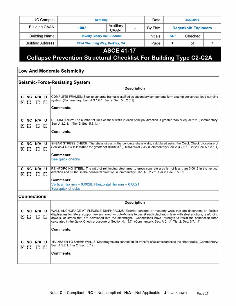
Collapse Prevention Structural Checklist For Building Type C2-C2A
Note: C = Compliant NC = Noncompliant N/A = Not Applicable U = Unknown
Low And Moderate Seismicity
Seismic-Force-Resisting System
Description
C NC N/A U
COMPLETE FRAMES: Steel or concrete frames classified as secondary components form a complete vertical-load-carrying system. (Commentary: Sec. A.3.1.6.1. Tier 2: Sec. 5.5.2.5.1) Comments:
C NC N/A U
REDUNDANCY: The number of lines of shear walls in each principal direction is greater than or equal to 2. (Commentary: Sec. A.3.2.1.1. Tier 2: Sec. 5.5.1.1)
Comments:
C NC N/A U
SHEAR STRESS CHECK: The shear stress in the concrete shear walls, calculated using the Quick Check procedure of Section 4.4.3.3, is less than the greater of 100 lb/in.2 (0.69 MPa) or 2√f’c. (Commentary: Sec. A.3.2.2.1. Tier 2: Sec. 5.5.3.1.1)
Comments: See quick checks
C NC N/A U
REINFORCING STEEL: The ratio of reinforcing steel area to gross concrete area is not less than 0.0012 in the vertical direction and 0.0020 in the horizontal direction. (Commentary: Sec. A.3.2.2.2. Tier 2: Sec. 5.5.3.1.3)
Comments: Vertical rho min = 0.0028, Horizontal rho min = 0.0021 See quick checks
Connections
Description
C NC N/A U
WALL ANCHORAGE AT FLEXIBLE DIAPHRAGMS: Exterior concrete or masonry walls that are dependent on flexible diaphragms for lateral support are anchored for out-of-plane forces at each diaphragm level with steel anchors, reinforcing dowels, or straps that are developed into the diaphragm. Connections have strength to resist the connection force calculated in the Quick Check procedure of Section 4.4.3.7. (Commentary: Sec. A.5.1.1. Tier 2: Sec. 5.7.1.1)
Comments:
C NC N/A U
TRANSFER TO SHEAR WALLS: Diaphragms are connected for transfer of seismic forces to the shear walls. (Commentary: Sec. A.5.2.1. Tier 2: Sec. 5.7.2)
Comments:
Page 17

UC Campus: Berkeley Date: 2/20/2019
Building CAAN: 1002 Auxiliary CAAN:
- By Firm: Degenkolb Engineers
Building Name: Beverly Cleary Hall, Podium Initials: TAB Checked:
Building Address: 2424 Channing Way, Berkley, CA Page: 2 of 3
ASCE 41-17
Collapse Prevention Structural Checklist For Building Type C2-C2A
Note: C = Compliant NC = Noncompliant N/A = Not Applicable U = Unknown
C NC N/A U
FOUNDATION DOWELS: Wall reinforcement is doweled into the foundation with vertical bars equal in size and spacing to the vertical wall reinforcing directly above the foundation. (Commentary: Sec. A.5.3.5. Tier 2: Sec. 5.7.3.4)
Comments:
High Seismicity (Complete The Following Items In Addition To The Items For Low And Moderate Seismicity)
Seismic-Force-Resisting System
Description
C NC N/A U
DEFLECTION COMPATIBILITY: Secondary components have the shear capacity to develop the flexural strength of the components. (Commentary: Sec. A.3.1.6.2. Tier 2: Sec. 5.5.2.5.2)
Comments: Columns have adequate shear capacity to develop shear demands from flexural mechanism. See quick checks.
C NC N/A U
FLAT SLABS: Flat slabs or plates not part of the seismic-force-resisting system have continuous bottom steel through the column joints. (Commentary: Sec. A.3.1.6.3. Tier 2: Sec. 5.5.2.5.3)
Comments: Proper lap splice length provided at the column joints.
C NC N/A U
COUPLING BEAMS: The ends of both walls to which the coupling beam is attached are supported at each end to resist vertical loads caused by overturning. (Commentary: Sec. A.3.2.2.3. Tier 2: Sec. 5.5.3.2.1)
Comments:
Diaphragms (Stiff Or Flexible)
Description
C NC N/A U
DIAPHRAGM CONTINUITY: The diaphragms are not composed of split-level floors and do not have expansion joints. (Commentary: Sec. A.4.1.1. Tier 2: Sec. 5.6.1.1)
Comments:
C NC N/A U
OPENINGS AT SHEAR WALLS: Diaphragm openings immediately adjacent to the shear walls are less than 25% of the wall length. (Commentary: Sec. A.4.1.4. Tier 2: Sec. 5.6.1.3)
Comments:
Page 18

UC Campus: Berkeley Date: 2/20/2019
Building CAAN: 1002 Auxiliary CAAN:
- By Firm: Degenkolb Engineers
Building Name: Beverly Cleary Hall, Podium Initials: TAB Checked:
Building Address: 2424 Channing Way, Berkley, CA Page: 3 of 3
ASCE 41-17
Collapse Prevention Structural Checklist For Building Type C2-C2A
Note: C = Compliant NC = Noncompliant N/A = Not Applicable U = Unknown
Flexible Diaphragms
Description
C NC N/A U
CROSS TIES: There are continuous cross ties between diaphragm chords. (Commentary: Sec. A.4.1.2. Tier 2: Sec. 5.6.1.2)
Comments:
C NC N/A U
STRAIGHT SHEATHING: All straight-sheathed diaphragms have aspect ratios less than 2-to-1 in the direction being considered. (Commentary: Sec. A.4.2.1. Tier 2: Sec. 5.6.2)
Comments:
C NC N/A U
SPANS: All wood diaphragms with spans greater than 24 ft (7.3 m) consist of wood structural panels or diagonal sheathing. (Commentary: Sec. A.4.2.2. Tier 2: Sec. 5.6.2)
Comments:
C NC N/A U
DIAGONALLY SHEATHED AND UNBLOCKED DIAPHRAGMS: All diagonally sheathed or unblocked wood structural panel diaphragms have horizontal spans less than 40 ft (12.2 m) and aspect ratios less than or equal to 4-to-1. (Commentary: Sec. A.4.2.3. Tier 2: Sec. 5.6.2)
Comments:
C NC N/A U
OTHER DIAPHRAGMS: Diaphragms do not consist of a system other than wood, metal deck, concrete, or horizontal bracing. (Commentary: Sec. A.4.7.1. Tier 2: Sec. 5.6.5)
Comments:
Connections
Description
C NC N/A U
UPLIFT AT PILE CAPS: Pile caps have top reinforcement, and piles are anchored to the pile caps. (Commentary: Sec. A.5.3.8. Tier 2: Sec. 5.7.3.5)
Comments: Shallow spread footings
Page 19

UC Campus: Berkeley Date: 2/20/2019
Building CAAN: 1002 Auxiliary CAAN:
- By Firm: Degenkolb Engineers
Building Name: Beverly Cleary Hall - Podium Initials: TAB Checked:
Building Address: 2424 Channing Way, Berkeley, CA Page: 1 of 4
ASCE 41-17
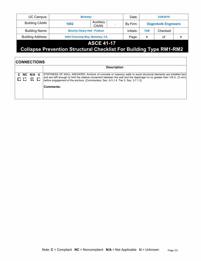
Collapse Prevention Structural Checklist For Building Type RM1-RM2
Note: C = Compliant NC = Noncompliant N/A = Not Applicable U = Unknown
LOW AND MODERATE SEISMICITY
SEISMIC-FORCE-RESISTING SYSTEM
Description
C NC N/A U
REDUNDANCY: The number of lines of shear walls in each principal direction is greater than or equal to 2. (Commentary: Sec. A.3.2.1.1. Tier 2: Sec. 5.5.1.1)
Comments:
C NC N/A U
SHEAR STRESS CHECK: The shear stress in the reinforced masonry shear walls, calculated using the Quick Check procedure of Section 4.4.3.3, is less than 70 lb/in.2 (0.48 MPa). (Commentary: Sec. A.3.2.4.1. Tier 2: Sec. 5.5.3.1.1)
Comments: CMU walls in the East-West Direction contribute to shear resistance and have stresses > 70 psi See Quick Checks
C NC N/A U
REINFORCING STEEL: The total vertical and horizontal reinforcing steel ratio in reinforced masonry walls is greater than 0.002 of the wall with the minimum of 0.0007 in either of the two directions; the spacing of reinforcing steel is less than 48 in. (1220 mm), and all vertical bars extend to the top of the walls. (Commentary: Sec. A.3.2.4.2. Tier 2: Sec. 5.5.3.1.3)
Comments:
STIFF DIAPHRAGMS
Description
C NC N/A U
TOPPING SLAB: Precast concrete diaphragm elements are interconnected by a continuous reinforced concrete topping slab. (Commentary: Sec. A.4.5.1. Tier 2: Sec. 5.6.4)
Comments:
CONNECTIONS
Description
C NC N/A U
WALL ANCHORAGE: Exterior concrete or masonry walls that are dependent on the diaphragm for lateral support are anchored for out-of-plane forces at each diaphragm level with steel anchors, reinforcing dowels, or straps that are developed into the diaphragm. Connections have strength to resist the connection force calculated in the Quick Check procedure of Section 4.4.3.7. (Commentary: Sec. A.5.1.1. Tier 2: Sec. 5.7.1.1)
Comments:
Page 20

UC Campus: Berkeley Date: 2/20/2019
Building CAAN: 1002 Auxiliary CAAN:
- By Firm: Degenkolb Engineers
Building Name: Beverly Cleary Hall - Podium Initials: TAB Checked:
Building Address: 2424 Channing Way, Berkeley, CA Page: 2 of 4
ASCE 41-17
Collapse Prevention Structural Checklist For Building Type RM1-RM2
Note: C = Compliant NC = Noncompliant N/A = Not Applicable U = Unknown
C NC N/A U
WOOD LEDGERS: The connection between the wall panels and the diaphragm does not induce cross-grain bending or tension in the wood ledgers. (Commentary: Sec. A.5.1.2. Tier 2: Sec. 5.7.1.3)
Comments:
C NC N/A U
TRANSFER TO SHEAR WALLS: Diaphragms are connected for transfer of seismic forces to the shear walls. (Commentary: Sec. A.5.2.1. Tier 2: Sec. 5.7.2)
Comments:
C NC N/A U
TOPPING SLAB TO WALLS OR FRAMES: Reinforced concrete topping slabs that interconnect the precast concrete diaphragm elements are doweled for transfer of forces into the shear wall or frame elements. (Commentary: Sec. A.5.2.3. Tier 2: Sec. 5.7.2)
Comments:
C NC N/A U
FOUNDATION DOWELS: Wall reinforcement is doweled into the foundation. (Commentary: Sec. A.5.3.5. Tier 2: Sec. 5.7.3.4)
Comments:
C NC N/A U
GIRDER–COLUMN CONNECTION: There is a positive connection using plates, connection hardware, or straps between the girder and the column support. (Commentary: Sec. A.5.4.1. Tier 2: Sec. 5.7.4.1)
Comments:
HIGH SEISMICITY (COMPLETE THE FOLLOWING ITEMS IN ADDITION TO THE ITEMS FOR LOW AND MODERATE SEISMICITY)
STIFF DIAPHRAGMS
Description
C NC N/A U
OPENINGS AT SHEAR WALLS: Diaphragm openings immediately adjacent to the shear walls are less than 25% of the wall length. (Commentary: Sec. A.4.1.4. Tier 2: Sec. 5.6.1.3)
Comments:
C NC N/A U
OPENINGS AT EXTERIOR MASONRY SHEAR WALLS: Diaphragm openings immediately adjacent to exterior masonry shear walls are not greater than 8 ft (2.4 m) long. (Commentary: Sec. A.4.1.6. Tier 2: Sec. 5.6.1.3)
Comments:
Page 21

UC Campus: Berkeley Date: 2/20/2019
Building CAAN: 1002 Auxiliary CAAN:
- By Firm: Degenkolb Engineers
Building Name: Beverly Cleary Hall - Podium Initials: TAB Checked:
Building Address: 2424 Channing Way, Berkeley, CA Page: 3 of 4
ASCE 41-17
Collapse Prevention Structural Checklist For Building Type RM1-RM2
Note: C = Compliant NC = Noncompliant N/A = Not Applicable U = Unknown
FLEXIBLE DIAPHRAGMS
Description
C NC N/A U
CROSS TIES: There are continuous cross ties between diaphragm chords. (Commentary: Sec. A.4.1.2. Tier 2: Sec. 5.6.1.2)
Comments:
C NC N/A U
OPENINGS AT SHEAR WALLS: Diaphragm openings immediately adjacent to the shear walls are less than 25% of the wall length. (Commentary: Sec. A.4.1.4. Tier 2: Sec. 5.6.1.3)
Comments:
C NC N/A U
OPENINGS AT EXTERIOR MASONRY SHEAR WALLS: Diaphragm openings immediately adjacent to exterior masonry shear walls are not greater than 8 ft (2.4 m) long. (Commentary: Sec. A.4.1.6. Tier 2: Sec. 5.6.1.3)
Comments:
C NC N/A U
STRAIGHT SHEATHING: All straight-sheathed diaphragms have aspect ratios less than 2-to-1 in the direction being considered. (Commentary: Sec. A.4.2.1. Tier 2: Sec. 5.6.2)
Comments:
C NC N/A U
SPANS: All wood diaphragms with spans greater than 24 ft (7.3 m) consist of wood structural panels or diagonal sheathing. (Commentary: Sec. A.4.2.2. Tier 2: Sec. 5.6.2)
Comments:
C NC N/A U
DIAGONALLY SHEATHED AND UNBLOCKED DIAPHRAGMS: All diagonally sheathed or unblocked wood structural panel diaphragms have horizontal spans less than 40 ft (12.2 m) and aspect ratios less than or equal to 4-to-1. (Commentary: Sec. A.4.2.3. Tier 2: Sec. 5.6.2)
Comments:
C NC N/A U
OTHER DIAPHRAGMS: Diaphragms do not consist of a system other than wood, metal deck, concrete, or horizontal bracing. (Commentary: Sec. A.4.7.1. Tier 2: Sec. 5.6.5)
Comments:
Page 22
UC Campus: Berkeley Date: 2/20/2019
Building CAAN: 1002 Auxiliary CAAN:
- By Firm: Degenkolb Engineers
Building Name: Beverly Cleary Hall - Podium Initials: TAB Checked:
Building Address: 2424 Channing Way, Berkeley, CA Page: 4 of 4
ASCE 41-17
Collapse Prevention Structural Checklist For Building Type RM1-RM2
Note: C = Compliant NC = Noncompliant N/A = Not Applicable U = Unknown
CONNECTIONS
Description
C NC N/A U
STIFFNESS OF WALL ANCHORS: Anchors of concrete or masonry walls to wood structural elements are installed taut and are stiff enough to limit the relative movement between the wall and the diaphragm to no greater than 1/8 in. (3 mm) before engagement of the anchors. (Commentary: Sec. A.5.1.4. Tier 2: Sec. 5.7.1.2)
Comments:
Page 23

Building Name: Beverly Cleary Hall South Evaluator: TAB
CAAN ID: 1002 Date: 02/19/19
APPENDIX C
UCOP Seismic Safety Policy Falling Hazards Assessment Summary
Page 24

UC Campus: Berkeley Date: 2/14/2019
Building CAAN: 1002 Auxiliary CAAN:
1002.0 By Firm: DEGENKOLB ENGINEERS
Building Name: Beverly Cleary Hall - South Initials: TAB Checked:
Building Address: 2424 Channing Way, Berkeley, CA Page: 1 of 1
UCOP SEISMIC SAFETY POLICY
Falling Hazard Assessment Summary
Note: P= Present, N/A = Not Applicable
Description
P N/A
Heavy ceilings, features or ornamentation above large lecture halls, auditoriums, lobbies, or other areas where large numbers of people congregate (50 ppl or more)
Comments:
P N/A
Heavy masonry or stone veneer above exit ways or public access areas
Comments:
P N/A
Unbraced masonry parapets, cornices, or other ornamentation above exit ways or public access areas
Comments:
P N/A
Unrestrained hazardous material storage
Comments:
P N/A
Masonry chimneys
Comments:
P N/A
Unrestrained natural gas-fueled equipment such as water heaters, boilers, emergency generators, etc.
Comments:
P N/A
Other:
Comments:
P N/A
Other:
Comments:
P N/A
Other:
Comments:
Falling Hazard Risk: Low
Page 25

Building Name: Beverly Cleary Hall South Evaluator: TAB
CAAN ID: 1002 Date: 02/19/19
APPENDIX D
ASCE 41-17 Quick Check Calculations
Page 26

Degenkolb Engineers
375 Beale St. Ste. 500
San Francisco, CA 94105
Phone: 415.392.6952
Subject: Weight Take Off Job Number: B8114004.00 Date: 3/7/2019
Job: Cleary Hall South By: TAB Section:
Checked By: Page/of:
Roof
Area Length Height Area Weight Weight
ft2 ft ft psf lbf
Roof 4600.0 21 96600.0
Exterior Walls 397 4.6 18 32871.6
Interior Bearing 475 4.6 10 21850.0
Interior Non-Bearing 210 4.6 7 6762.0
Σ Wfloor 158.1 kip
Fourth Floor
Area Length Height Area Weight Weight
ft2 ft ft psf lbf
Floor 4600.0 19 87400.0
Exterior Walls 397 9.2 18 65743.2
Interior Bearing 475 9.2 10 43700.0
Interior Non-Bearing 210 9.2 7 13524.0
Σ Wfloor 210.4 kip
Third Floor
Area Length Height Area Weight Weight
ft2 ft ft psf lbf
Floor 4600.0 19 87400.0
Exterior Walls 397 9.2 18 65743.2
Interior Bearing 475 9.2 10 43700.0
Interior Non-Bearing 210 9.2 7 13524.0
Σ Wfloor 210.4 kip
Second
Area Length Height Area Weight Weight
ft2 ft ft psf lbf
Floor 4600.0 19 87400.0
Exterior Walls 397 9.2 18 65743.2
Interior Bearing 475 9.2 10 43700.0
Interior Non-Bearing 210 9.2 7 13524.0
Σ Wfloor 210.4 kip
Building Weight = 789.2 kip
Item
Item
Item
Item
Page 27

Subject: Base forces Job Number: B8114004 Date: 3/7/2019
Job: Cleary Hall South By: TAB
Checked By:
ASCE 41-17 Linear Static Base Shear & Vertical Force DistributionTier 1
INPUT DATA
C: Modification factor (Table 4-7) = 1
S1: Spectral Response Acceleration @ 1 sec. = 1.00 (from MCE maps or Site Specific)
Ss: Short Period Response Acceleration = 2.41 (from MCE maps or Site Specific)
SC: C (A through F), 1.6.1.4.1
Table 1-5: S1 <= S1 = S1 = S1 = S1 >=
0.1 0.2 0.3 0.4 0.5
Soil Class C 1.7 1.6 1.5 1.4 1.3
F v - - - - 1.30
Fv: Site Coefficient for S1 = 1.30 (Table 11.4-1)
Table 1-4: Ss <= Ss = Ss = Ss = Ss >=
0.25 0.50 0.75 1.00 1.25
Soil Class C 1.2 1.2 1.1 1.0 1.0
F a - - - - 1.00
Fa: Site Coefficient for Ss = 1.00 (Table 11.4-2)
SX1: Spectral Response Acceleration @ 1 sec. = 1.30 (2-2)
Sxs: Short Period Acceleration = Fa*Ss = 2.41 (2-1)
b: Building System Exponent = 0.75 (4.4.2.4)
Ct: Building System Coefficient = 0.02 (4.4.2.4)
W: Total Building Weight = 789 kips
hn: Total Building Height = 47.6 feet
n: Number of Stories = 4
CALCULATE BASE SHEAR FOR BSE-2 (MCE)
T: Fundamental Period of Vibration = Ct * hb = 0.363 sec. (4-4)
Sa: Spectral Acceleration at Building Period = 2.41 (4-3)
V: Pseudo Seismic Force = 1902 kips (4-1)
Soil Class =
Page 28

Subject: Shear Stress Check 4.4.3.3 Job Number: B8114004 Date: 3/7/2019
Job: Cleary Hall South By: TAB
Checked By:
Considering Wall with hold down both ends of wall
Double Double Counts when Wall Double Sided
North-South Loading
Lwall = 401 ft
Ms = 4.5 for wood wall, Collapse Prevention
Aw = 401
Vbase= 1902 kip
vj-avg = 1054 plf
East-West Loading
Lwall = 405 ft
Ms = 4.5 for wood wall, Collapse Prevention
Aw = 405
Vbase= 1902 kip
vj-avg = 1044 plf
Page 29

Degenkolb Engineers375 Beale St. Ste 500San Francisco, CA 94105Phone: 415.392.6952
Subject: Weight Take Off Job Number: B8114004.00 Date: 7/11/2019Job: Cleary Hall Podium By: TAB Section:
Checked By: Page/of:
Roof
South Building 158.1 kipNorth Building 149 kip
Σ Wfloor 307 kip
Fourth Floor
South Building 210.4 kipNorth Building 193 kip
Σ Wfloor 403 kip
Third Floor
South Building 210.4 kipNorth Building 227 kip
Σ Wfloor 438 kip
Second Floor
South Building 210.4 kipNorth Building 215 kip
Σ Wfloor 425.8 kip
First Floor
Total Area Length Height Area Weight Weight
# ft2 ft ft psf lbf
Exterior Walls - Main 731 4.6 18 60527Exterior Walls - Aux 137 4.6 18 11344Interior Bearing 926 4.6 10 42596Interior Non-Bearing 342 4.6 7 1101212.5" Conc. Slab 32000 1.04 156.25 50000002.5" Conc. Topping 14500 0.21 31.25 45312518" Ø Column 18 1.77 6.13 918.75 29224Concrete Wall 400.25 6.13 150 367730CMU Wall 475.75 6.13 150 437095
Σ Wfloor 6413 kip
Total Building Weight = 7986 kip
Item
Page 30

Subject: Base forces Job Number: B8114004 Date: 7/11/2019
Job: Cleary Hall Podium By: TABChecked By:
ASCE 41-17 Linear Static Base Shear & Vertical Force DistributionTier 1
INPUT DATA
C: Modification factor (Table 4-7) = 1S1: 1.00 (from MCE maps or Site Specific)
Ss: Short Period Response Acceleration = 2.41 (from MCE maps or Site Specific)SC: D (A through F), 1.6.1.4.1
Table 1-5: S1 <= S1 = S1 = S1 = S1 >=0.1 0.2 0.3 0.4 0.5
Soil Class D 2.4 2.0 1.8 1.6 1.5 F v - - - - 1.50
Fv: Site Coefficient for S1 = 1.50 (Table 11.4-1)
Table 1-4: Ss <= Ss = Ss = Ss = Ss >=0.25 0.50 0.75 1.00 1.25
Soil Class D 1.6 1.4 1.2 1.1 1.0 F a - - - - 1.00
Fa: Site Coefficient for Ss = 1.00 (Table 11.4-2)SX1: Spectral Response Acceleration @ 1 sec. = 1.50 (2-2)
Sxs: Short Period Acceleration = Fa*Ss = 2.41 (2-1)b: Building System Exponent = 0.75 (4.4.2.4)Ct: Building System Coefficient = 0.02 (4.4.2.4)W: Total Building Weight = 7986 kipshn: Total Building Height = 67.9 feetn: Number of Stories = 4
CALCULATE BASE SHEAR FOR BSE-2 (MCE)
T: Fundamental Period of Vibration = Ct * hb = 0.473 sec. (4-3)
Sa: Spectral Acceleration at Building Period = 2.41 g (4-1)V Pseudo Seismic Force = 19247 kips
Soil Class =
Page 31

Subject: Shear Stress Check 4.4.3.3 Job Number: B8114004 Date: 7/11/2019
Job: Cleary Hall Podium By: TABChecked By:
Considering CMU and Concrete Wall
North-South Loading
Lwall = 679 fttwall = 12 in
Ms = 4.5 for Concrete o/ CMU wall, Collapse Prevention
Aw = 97776 in2
Vbase= 19247 kipvj-avg = 44 psi
East-West Loading
Lwall = 249 fttwall = 12 in
Ms = 4.5 for Concrete o/ CMU wall, Collapse PreventionAw = 35856
Vbase= 19247 kipvj-avg = 119 psi
East-West Loading
Lwall = 196 ft Only Considering Concretetwall = 12 in
Ms = 4.5 for Concrete o/ CMU wall, Collapse PreventionAw = 28224
Vbase= 19247 kip
Veff= 18710 kip subtracted CMU contribution based on 70psi
vj-avg = 147 psi
f'ce= 6000 psi f'ce= 4000 psi2 √f'ce = 155 psi 2 √f'c = 126 psi
Page 32

Subject: Wall Steel Reinforcement Ratio Job Number: B8114004 Date: 7/11/2019
Job: Cleary Hall Podium By: TABChecked By:
Concrete Walls
Vertical: #4 at 12" o.c., each way, both facestwall = 12 inAbar = 0.2 in2
spacing = 12 inrho = 0.0028 OK > 0.0012 vertical minimum ratio
Vertical: #4 at 12" o.c., each way, both facestwall = 12 inAbar = 0.2 in2
spacing = 16 inrho = 0.0021 OK > 0.002 horizontal minimum ratio
Vertical: #4 at 12" o.c., each way, both facestwall = 12 inAbar = 0.2 in2
spacing = 12 inrho = 0.0028 OK > 0.0012 vertical minimum ratio
Vertical: #4 at 12" o.c., each way, both facestwall = 12 inAbar = 0.2 in2
spacing = 12 inrho = 0.0028 OK > 0.002 horizontal minimum ratio
Wall Type 'A'
Wall Type 'E'
Page 33

CMU Walls
Vertical: #4 at 16" o.c., each way, both facestwall = 12 inAbar = 0.2 in2
spacing = 16 inrho = 0.0021 OK > 0.0007 minimum ratio
Horziontal #4 at 24" o.c., each way, both facestwall = 12 inAbar = 0.2 in2
spacing = 24 inrho = 0.0014 OK > 0.0007 minimum ratio
rhototal = 0.0035 > 0.002 combined horz/vert
Vertical: #4 at 16" o.c., each way, both facestwall = 12 inAbar = 0.2 in2
spacing = 16 inrho = 0.0021 OK > 0.0007 minimum ratio
Vertical: #4 at 24" o.c., each way, both facestwall = 12 inAbar = 0.2 in2
spacing = 24 inrho = 0.0014 OK > 0.0007 minimum ratio
rhototal = 0.0035 > 0.002 combined horz/vert
Wall Type 'B'
Wall Type 'C'
Page 34

Subject: Column Deflection Compatability Job Number: B8114004 Date: 7/11/2019
Job: Cleary Hall Podium By: TABChecked By:
Material Propertiesfy = 60 ksi f'c = 4000 psi
fye = 75 ksi f'ce = 6000 psi
Section Moment CapacityUsing Expected Material Properties
Mmax = 322 k-ft @ 242 k Axiallyl = 10.25 ft
Vlsa = 62.8 kipØ 18
Shear CapacityShear Design @ Hinge3 #3 @ 12" oc
Av = 0.33 in2
s = 12 ind = 14.4 in 0.8 x Ø (column diameter)
fyE = 75 ksiλ = 1
knl = 1 displacement ductility factorMud/Vud*d = 4
αcol = 1Ag = 254 in^2
Vcol = 111.7 kip ASCE 41-17, EQ (10-3)
Axial Load172 psf200 psf
L1 22 ftL2 25.66 ft
Atrib 565 ft2
Wstruct 97 kip
Wpodium 113 kip
Wcolum 210 kip
Timber StructurePodium Weight
Page 35