artisan technology group is your source for quality ... · encoder plug motor plug ul20276 magnetic...
TRANSCRIPT

Artisan Technology Group is your source for quality new and certified-used/pre-owned equipment
• FAST SHIPPING AND DELIVERY
• TENS OF THOUSANDS OF IN-STOCK ITEMS
• EQUIPMENT DEMOS
• HUNDREDS OF MANUFACTURERS SUPPORTED
• LEASING/MONTHLY RENTALS
• ITAR CERTIFIED SECURE ASSET SOLUTIONS
SERVICE CENTER REPAIRSExperienced engineers and technicians on staff at our full-service, in-house repair center
WE BUY USED EQUIPMENTSell your excess, underutilized, and idle used equipment We also offer credit for buy-backs and trade-inswww.artisantg.com/WeBuyEquipment
REMOTE INSPECTIONRemotely inspect equipment before purchasing with our interactive website at www.instraview.com
LOOKING FOR MORE INFORMATION? Visit us on the web at www.artisantg.com for more information on price quotations, drivers, technical specifications, manuals, and documentation
Contact us: (888) 88-SOURCE | [email protected] | www.artisantg.com
SMViewInstra
Sigma Mini Servo System Product Catalog Supplement
Sigma Mini Servo SystemProduct Catalog Supplement
Artisan Technology Group - Quality Instrumentation ... Guaranteed | (888) 88-SOURCE | www.artisantg.com

3
Table of Contents
SGMM Ratings & Specifications......................................................................5 - 6
SGMM Speed/Torque Curves............................................................................... 7
SGMM Dimensions..........................................................................................8 - 9
SGMM Selection/Ordering Information........................................................10 - 14
SGDF Ratings & Specifications ...................................................................15 - 17
SGDF Dimensions .............................................................................................. 18
SGDF Internal Connection Diagrams..........................................................19 - 22
Overload Characteristics..................................................................................... 23
Cable Specifications and Peripheral Devices..............................................24 - 26
SGMM Sigma Mini Servo System
SGDF Sigma Mini Servo Amplifier
Artisan Technology Group - Quality Instrumentation ... Guaranteed | (888) 88-SOURCE | www.artisantg.com

Table of Contents
NOTES:
Artisan Technology Group - Quality Instrumentation ... Guaranteed | (888) 88-SOURCE | www.artisantg.com
SGMM Sigma Mini Servo System
5
SG
MM
Design Features
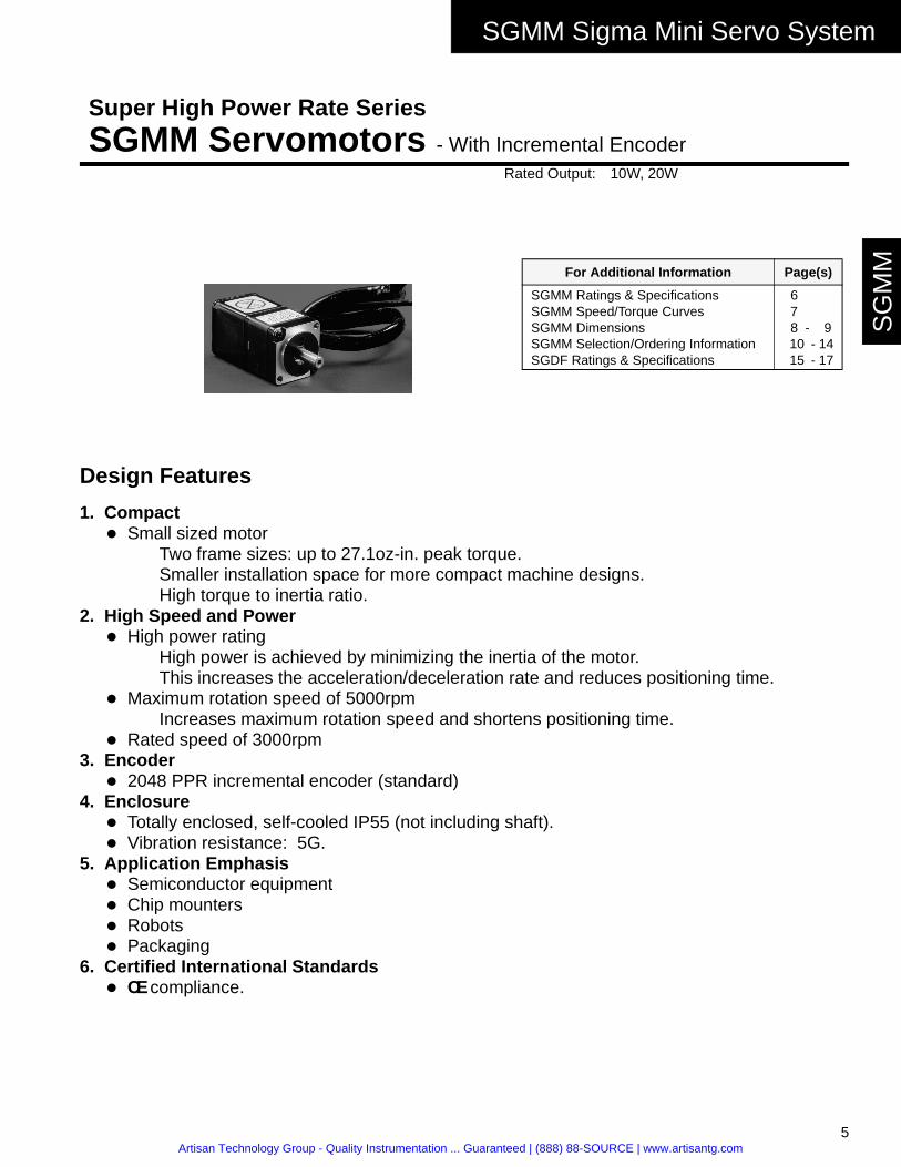
1. Compact! Small sized motor
Two frame sizes: up to 27.1oz-in. peak torque.Smaller installation space for more compact machine designs.High torque to inertia ratio.
2. High Speed and Power! High power rating
High power is achieved by minimizing the inertia of the motor. This increases the acceleration/deceleration rate and reduces positioning time.
! Maximum rotation speed of 5000rpmIncreases maximum rotation speed and shortens positioning time.
! Rated speed of 3000rpm3. Encoder
! 2048 PPR incremental encoder (standard)4. Enclosure
! Totally enclosed, self-cooled IP55 (not including shaft).! Vibration resistance: 5G.
5. Application Emphasis! Semiconductor equipment! Chip mounters! Robots! Packaging
6. Certified International Standards! CE compliance.
Super High Power Rate Series
SGMM Servomotors - With Incremental EncoderRated Output: 10W, 20W
For Additional Information Page(s)
SGMM Ratings & SpecificationsSGMM Speed/Torque CurvesSGMM DimensionsSGMM Selection/Ordering Information SGDF Ratings & Specifications
67
8 - 9 10 - 14 15 - 17
Artisan Technology Group - Quality Instrumentation ... Guaranteed | (888) 88-SOURCE | www.artisantg.com

SGMM Sigma Mini Servo System
6
SG
MM
Servomotor Ratings and Specifications
*Values when servomotor is combined with SGDF servo amplifier.
Time Rating: ContinuousInsulation: Class BVibration: 15µm or lessWithstand Voltage: 1000VACInsulation Resistance: 500VDC
10MΩ minimum
Enclosure: Totally-enclosed, self-cooledAmbient Temperature: 0 to 40ºCAmbient Humidity: 20 to 80%
(non-condensing)Rated Rotation Speed: 3000rpmMax. Rotation Speed: 5000rpm
Excitation: Permanent magnetDrive Method: Direct driveMounting: Flange-mountedApplicable Encoder: Incremental encoder 2048PPR
Applied Voltage
MOTOR: SGMM-
Rate OutputW (hp)
RatedTorque
oz • in (N • m)
Instantaneous Peak Torqueoz • in (N • m)
ContinuousRated Current*
Arms
MaximumPeak
.Current*Arms
RatedAngular
Accelerationrad/s2
RatedPower Rating
KW/s
24VDC
A1" 10 (0.013) 4.5 (0.0318) 13.5 (0.0955) 2.1 6.0 90000 2.9
A2" 20 (0.027) 9.02 (0.0637) 27.1 (0.191) 2.0 5.7 120000 7.4
Applied Voltage
MOTORSGMM-
Moment of Inertia (JM) Holding Brake (at 20°C)Allowable Load
Inertia (JL)Motor without Brake Motor with Brake Capacity TorqueCoil
Resis-tance
Rated Current
oz • in • s2 × 10-3
(kgf • m2 × 10-4) oz • in • s2 × 10-3
(kgf • m2 × 10-4)W kgf • m Ω A
oz • in • s2 × 10-3
(kg • m2 × 10-4)
24VDC
A1" 0.0501(0.00354)
0.069(0.00487)
2 0.325 320 0.075 1.5072(0.1064)
A2" 0.0776(0.00548)
0.0967(0.00683)
2.6 0.65 221.5 0.108 2.4832(0.164)
Artisan Technology Group - Quality Instrumentation ... Guaranteed | (888) 88-SOURCE | www.artisantg.com
SGMM Sigma Mini Servo System
7
SG
MM
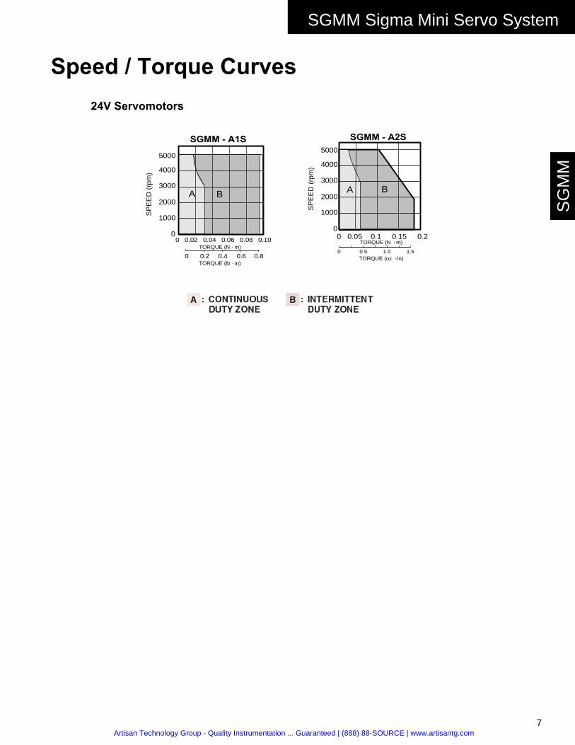
Speed / Torque Curves
SGMM - A1SS
PE
ED
(rp
m) 4000
3000
2000
1000
5000
0
BA
0 0.02 0.04 0.06 0.08 0.10TORQUE (N · m)
TORQUE (lb · in)0 0.2 0.4 0.6 0.8
SGMM - A2S
BA
SP
EE
D (
rpm
) 4000
3000
2000
1000
5000
00 0.05 0.1 0.15 0.2
0 0.5 1.0 1.5
TORQUE (N · m)
TORQUE (oz · in)
24V Servomotors
Artisan Technology Group - Quality Instrumentation ... Guaranteed | (888) 88-SOURCE | www.artisantg.com
SGMM Sigma Mini Servo System
8
SG
MM
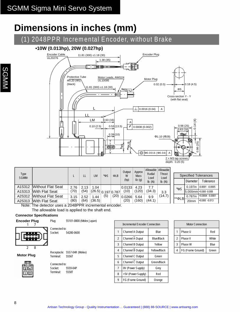
Dimensions in inches (mm)
•10W (0.013hp), 20W (0.027hp)
Note: The detector uses a 2048PPR incremental encoder.The allowable load is applied to the shaft end.
Connector Specifications
(1) 2048P P R Increm enta l E ncoder, w ithou t B rake
TypeSGMM- L LL LM *ΦS ΦLB
OutputW
(hp)
ApproxMass0z (g)
Allowable RadialLoadlb (N)
Allowable Thrust Loadlb (N)
Specified Tolerances
Diameter Tolerance A1S312 Without Flat Seat 2.76
(70)2.13(54)
1.04(26.5) 0.197
(5)0.787(20)
0.0133(10)
4.23(120)
7.7(34.3) 3.3
(14.7)
*ΦS 0.197in -0.0001 -0.0005
A1S313 With Flat Seat 5.000mm +0.000 -0.008
A2S312 Without Flat Seat 3.15(80)
2.52(64)
1.44(36.5)
0.0266(20)
5.64(160)
9.9(44.1) **ΦLB
0.787in +0.0004 -0.0001
A2S313 With Flat Seat 20mm +0.000 -0.013
Incremental Encoder Connection Motor Connection
1 Channel A Output Blue 1 Phase U Red
2 Channel A Ouput Blue/Black 2 Phase V White
3 Channel B Output Yellow 3 Phase W Blue
4 Channel B Output Yellow/Black 4 FG (Frame Ground) Green
5 Channel C Output Green
6 Channel C Output Green/Black
7 0V (Power Supply) Grey
8 +5V (Power Supply) Red
9 FG (Frame Ground) Orange
L
LLLM 0.63 (16)
*ΦS
**ΦLB
Y
Y
0.10 (2.5)
0.39 (10)
0.53 (13.5)
11.81 (300) ±1.18 (30)
11.81 (300) ±1.18 (30)
1.38 (35)
0.0016 (0.04) A
Φ0.0016 (Φ0.04) A
A
0.0008 (0.002) 0.98 (25)0.63 (16)
0.02 (0.5)
0.14
(4)
2 × M3 tap screwsdepth: 0.20 (5)
Φ1.10 (Φ28)
0.98
(25
)
Cross-section Y - Y(with flat seat)
0.18 (4.5)
ΦS
Encoder Plug
Motor Plug
Encoder Cable
Protective Tube Motor Leads, AWG24Φ0.20 (Φ5)(black)
UL10095
UL20276
Plug 55101-0800 (Molex Japan)
Connected to:Socket: 54280-0600
Receptacle: 5557-04R (Molex)Terminal: 5556T
Connected to:Socket: 5559-04PTerminal: 5558T
1 7
2 8
Encoder Plug
Motor Plug
Artisan Technology Group - Quality Instrumentation ... Guaranteed | (888) 88-SOURCE | www.artisantg.com

SGMM Sigma Mini Servo System
9
SG
MM
•10W (0.013hp), 20W (0.027hp)
Note: The detector uses a 2048PPR incremental encoder.The allowable load is applied to the shaft end.
Connector Specifications
(2) 2048PPR Incremental Encoder, with Brake
TypeSGMM- QK L LL LM *ΦS ΦLB
OutputW
(hp)
ApproxMass0z (g)
Allowable RadialLoadlb (N)
Allowable Thrust Loadlb (N)
Specified Tolerances
Diameter Tolerance A1S312C Without Flat Seat 3.72
(94.5)3.09
(78.5)1.04
(26.5) 0.197(5)
0.787(20)
0.0133(10)
7.23(205)
7.7(34.3) 3.3
(14.7)
*ΦS 0.197in -0.0001 -0.0005
A1S313C With Flat Seat 5.000mm +0.000 -0.008
A2S312C Without Flat Seat 4.27(108.5)
3.64(92.5)
1.44(36.5)
0.0266(20)
9.17(260)
9.9(44.1) **ΦLB
0.787in +0.0004 -0.0001
A2S313C With Flat Seat 20mm +0.000 -0.013
Incremental Encoder Connection Motor Connection
1 Channel A Ouput Blue 1 Phase U Red
2 Channel A Ouput Blue/Black 2 Phase V White
3 Channel B Output Yellow 3 Phase W Blue
4 Channel B Output Yellow/Black 4 FG (Frame Ground) Green
5 Channel C Output Green 5 Brake Terminal Black
6 Channel C Output Green/Black 6 Brake Terminal Black
7 0V (Power Supply) Grey
8 +5V (Power Supply) Red
9 FG (Frame Ground) Orange
Cross-section Y - Y(with flat seat)
L
LLLM 0.63 (16)
*ΦS
**ΦLB
Y
Y
0.10 (2.5)
0.39 (10)
0.53 (13.5)
11.81 (300) ±1.18 (30)
11.81 (300) ±1.18 (30)
1.38 (35)
0.0016 (0.04) A
Φ0.0016 (Φ0.04) A
A
0.0008 (0.02)
0.98 (25)
0.02 (0.5)
0.14
(4)
2 × M 3 tap screwsdepth : 0.20 (5)
Φ1.10 (Φ28)
0.98
(25
)
0.18
ΦS
Encoder Cable
Protective Tube
Motor Leads, AWG24
Φ0.20 (Φ5)(black)
UL10095
(4.5)
Encoder Plug
Motor Plug
UL20276
M agnetic brake Non-excitation opera tonDC power supp ly: 24VM axim um capacity: 3W
Plug 55101-0800 (Molex Japan)
Connected to:Socket: 54280-0800
Receptacle: 5557-06R (Molex)Terminal: 5556T
Connected to:Socket: 5559-06PTerminal: 5558T
1 7
2 8
Encoder Plug
Motor Plug
Artisan Technology Group - Quality Instrumentation ... Guaranteed | (888) 88-SOURCE | www.artisantg.com

SGMM Sigma Mini Servo System
10
SG
MM
Selecting Your SGMM Sigma Mini Servo SystemFirst, select the Sigma servomotor suited for your application using SigmaSize: the Yaskawa servomotor sizing software, available at no charge. (Request SigmaSize software via e-mail, at: [email protected]).Use the diagram below to locate and identify the components of your system. Each item is letter-coded and cross-referenced in the option tables on the following pages.
Note: Model number designations printed in boldface type represent stock items. Please contact Yaskawa for delivery on all other items. The model number designation is provided for reference only.
Amplifier
Digital Operator (E)
CN5
CN1 Encoder Cable (C)
Motor Cable (C)
CN2
Servomotor
Motor sideConnector (D)
Encoder sideConnector (D)
Connector Encoder (D)
I/O SignalConnector
(A)
(B)
Straight Shaft
(D)
Peripheral SignalCable (E)
SGDF Servo
SGMM
System Configuration
CN3 (D)
24VDCPowerSupply
CN4 (D)
Model Number Designation
Sigma Mini Servomotor TypeRated Output
A1: 10W (0.013hp)A2: 20W (0.027hp)
Power SupplyS: 24VDC
AccessoriesC: 24VDC Brake
Shaft Specifications3: Straight Shaft with Flat Seat2: Straight Shaft without Flat Seat
Revision LevelEncoder Specifications
3: 2048PPR Incremental Encoder
SGMM - A1 S 3 1 2
Artisan Technology Group - Quality Instrumentation ... Guaranteed | (888) 88-SOURCE | www.artisantg.com

SGMM Sigma Mini Servo System
11
SG
MM
Use the table below to select the recommended SGMM Sigma Mini Servomotor and Ampli-fier.
Notes: 24VDC brakes for SGMM Sigma Mini servomotors are standard. Contact a local source for 24VDC power supplies.Motor power and encoder cables are factory pre-wired with approximately 12” lead length with amplifier mating connectors.Use the tables on the following pages to specify mating connectors or pre-wired cables available in various lengths.For technical information, request manual number SIE-S800-27 from your Yaskawa representative.
* For more detailed SGDF amplifier specifications and dimensions, refer to page 17.
Servomotor & Amplifier Selection
Motors Used with Incremental Encoders (3000rpm Rated Speed) Amplifier
DescriptionPeak
Torque (oz. in.)
Rated Torque (oz. in.)
Motor Inertia (oz.in.s2×10-3)
Motor MODEL # (A)
Amplifier MODEL # (B)* Motor & Amplifier
Item ClassAnalog Input
SGDF-Digital Input
SGDF-
24VDC,
2048PPR
IncrementalEncoder
Straight Shaft without Flat Seat
13.5 4.5
0.0501 SGMM-A1S312
A1CS A1CP
Stock
0.0690 SGMM-A1S312C Limited Stock
27.1 9.02
0.0776 SGMM-A2S312
A2CS A2CP
Stock
0.0968 SGMM-A2S312C Limited Stock
Artisan Technology Group - Quality Instrumentation ... Guaranteed | (888) 88-SOURCE | www.artisantg.com
SGMM Sigma Mini Servo System
12
SG
MM
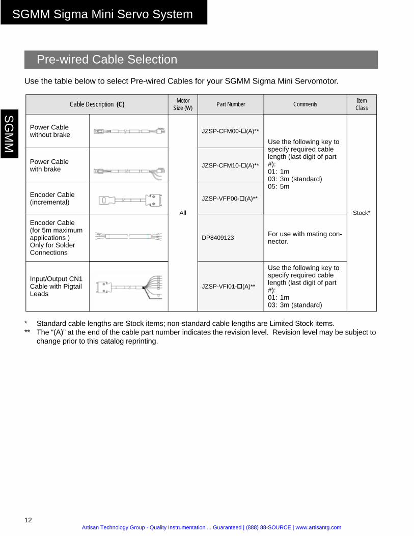
Use the table below to select Pre-wired Cables for your SGMM Sigma Mini Servomotor.
* Standard cable lengths are Stock items; non-standard cable lengths are Limited Stock items.** The “(A)” at the end of the cable part number indicates the revision level. Revision level may be subject to
change prior to this catalog reprinting.
Pre-wired Cable Selection
Cable Description (C) Motor Size (W) Part Number Comments Item
Class
Power Cablewithout brake
All
JZSP-CFM00-#(A)**
Use the following key to specify required cable length (last digit of part #):01: 1m 03: 3m (standard)05: 5m
Stock*
Power Cable with brake
JZSP-CFM10-#(A)**
Encoder Cable(incremental) JZSP-VFP00-#(A)**
Encoder Cable(for 5m maximum applications )Only for Solder Connections
DP8409123For use with mating con-nector.
Input/Output CN1 Cable with Pigtail Leads
JZSP-VFI01-#(A)**
Use the following key to specify required cable length (last digit of part #):01: 1m03: 3m (standard)
Artisan Technology Group - Quality Instrumentation ... Guaranteed | (888) 88-SOURCE | www.artisantg.com

SGMM Sigma Mini Servo System
13
SG
MM
Use the table below to select Mating Connectors or Kits for your SGMM Sigma Mini Servomotor.
Connector Selection
Connector Description (D) Motor Size (W) Part Number Comments Item Class
Motor PowerMating Connector(without Brake)
All
JZSP-CFM9-2
These connector kits include pin and socket.
Stock
Motor PowerMating Connector(with Brake)
JZSP-CFM9-3
CN4 Power Connector on servo amplifier side
JZSP-CFM9-1
Motor EncoderMating Connector
JZSP-VFP9-2 –
CN1 I/O Connector JZSP-VFP9 Connector for the amplifier side.
CN2 Encoder Con-nector JZSP-VFP9 Connector for the
servo amplifier side.
CN3 PowerConnector JZSP-CFG9 For 24VDC power
supply.Limited Stock
Artisan Technology Group - Quality Instrumentation ... Guaranteed | (888) 88-SOURCE | www.artisantg.com
SGMM Sigma Mini Servo System
14
SG
MM
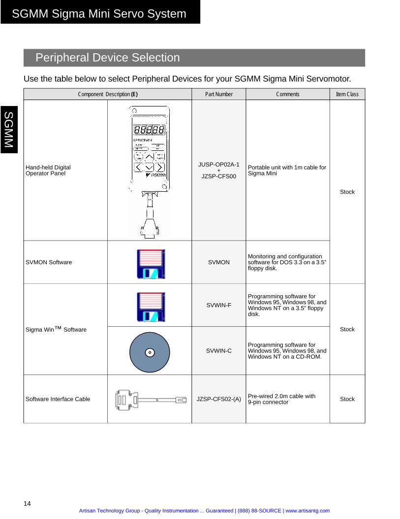
Use the table below to select Peripheral Devices for your SGMM Sigma Mini Servomotor.
Peripheral Device Selection
Component Description (E) Part Number Comments Item Class
Hand-held Digital Operator Panel
JUSP-OP02A-1+
JZSP-CFS00
Portable unit with 1m cable for Sigma Mini
Stock
SVMON Software SVMONMonitoring and configuration software for DOS 3.3 on a 3.5” floppy disk.
Sigma Win™ Software
SVWIN-F
Programming software for Windows 95, Windows 98, and Windows NT on a 3.5” floppy disk.
Stock
SVWIN-CProgramming software for Windows 95, Windows 98, and Windows NT on a CD-ROM.
Software Interface Cable JZSP-CFS02-(A) Pre-wired 2.0m cable with 9-pin connector Stock
Artisan Technology Group - Quality Instrumentation ... Guaranteed | (888) 88-SOURCE | www.artisantg.com
SGDF Sigma Mini Servo Amplifier
15
SG
DF
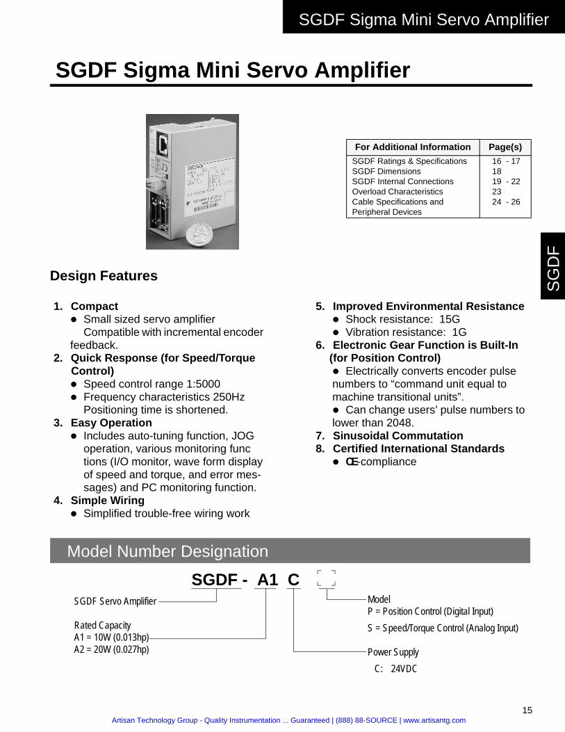
Design Features
SGDF Sigma Mini Servo Amplifier
For Additional Information Page(s)
SGDF Ratings & SpecificationsSGDF DimensionsSGDF Internal ConnectionsOverload CharacteristicsCable Specifications and Peripheral Devices
16 - 17 18 19 - 22 23 24 - 26
1. Compact! Small sized servo amplifier
Compatible with incremental encoder feedback.
2. Quick Response (for Speed/Torque Control)! Speed control range 1:5000! Frequency characteristics 250Hz
Positioning time is shortened.3. Easy Operation
! Includes auto-tuning function, JOG operation, various monitoring functions (I/O monitor, wave form display of speed and torque, and error mes-sages) and PC monitoring function.
4. Simple Wiring! Simplified trouble-free wiring work
5. Improved Environmental Resistance! Shock resistance: 15G! Vibration resistance: 1G
6. Electronic Gear Function is Built-In(for Position Control)! Electrically converts encoder pulse numbers to “command unit equal to machine transitional units”.! Can change users’ pulse numbers to lower than 2048.
7. Sinusoidal Commutation8. Certified International Standards
! CE-compliance
Model Number Designation
SGDF Servo Amplifier
Rated CapacityA1 = 10W (0.013hp)A2 = 20W (0.027hp)
SGDF - A1 C ModelP = Position Control (Digital Input)S = Speed/Torque Control (Analog Input)
Power Supply C: 24VDC
Artisan Technology Group - Quality Instrumentation ... Guaranteed | (888) 88-SOURCE | www.artisantg.com
SGDF Sigma Mini Servo Amplifier
16
SG
DF
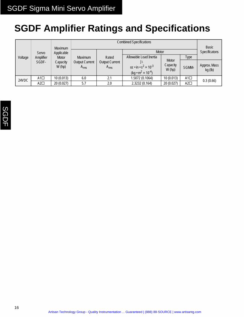
SGDF Amplifier Ratings and Specifications
VoltageServo
Amplifier SGDF-
Maximum Applicable
Motor Capacity W (hp)
Combined SpecificationsBasic
SpecificatonsMaximum
Output CurrentArms
RatedOutput Current
Arms
MotorAllowable Load Inertia
JL
oz • in • s2 × 10-3
(kg • m2 × 10-4)
Motor Capacity W (hp)
Type
SGMM- Approx. Mass kg (lb)
24VDC A1" 10 (0.013) 6.0 2.1 1.5072 (0.1064) 10 (0.013) A1" 0.3 (0.66)A2" 20 (0.027) 5.7 2.0 2.3232 (0.164) 20 (0.027) A2"
Artisan Technology Group - Quality Instrumentation ... Guaranteed | (888) 88-SOURCE | www.artisantg.com
SGDF Sigma Mini Servo Amplifier
17
SG
DF
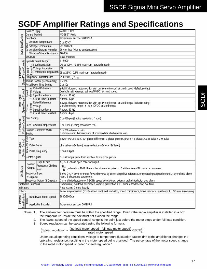
SGDF Amplifier Ratings and Specifications
Notes: 1. The ambient temperature must be within the specified range. Even if the servo amplifier is installed in a box, the temperature inside the box must not exceed the range.
2. The lowest speed of the speed control range is the point just before the motor stops under full-load condition.3 Speed regulation can be calculated using the following formula:
Under actual operating conditions, voltage or temperature fluctuation causes drift to the amplifier or changes the operating resistance, resulting in the motor speed being changed. The percentage of the motor speed change to the rated motor speed is called “speed regulation.”
Basic
Spe
cifica
tions
Power Supply 24VDC ±10% Control Method MOSFET-PWMFeedback Incremental encoder 2048PPR
Loca
tion Ambient Temperature 0 to 50°C1
Storage Temperature -20 to+85°CAmbient/Storage Humidity 90% or less (with no-condensation)Vibration/Shock Resistance 1G/15G
Structure Base-mounted
Perfo
rman
ce
(Spe
ed/To
rque
Con
trol) Speed Control Range2 1 : 5000
Spee
d 3
Regu
lation Load Regulation 0% to 100%: 0.01% maximum (at rated speed)
Voltage Regulation 0% Temperature Regulation 25 ± 25°C : 0.1% maximum (at rated speed)
Frequency Characteristics 250Hz (at JL = JM)Torque Control (Repeatability) ± 2.0%Accel/Decel Time Setting 0 to 10s
Input
Sign
al(S
peed
/Torq
ue C
ontro
l)Sp
eed
Refer
ence Rated Reference
Voltage±6VDC (forward motor rotation with positive reference) at rated speed (default setting)(variable setting range: ±2 to ±10VDC) at rated speed
Input Impedance Approx. 30 kΩCircuit Time Constant Approx. 47µs
Torq
ueRe
feren
ce Rated Reference Voltage
±3VDC (forward motor rotation with positive reference) at rated torque (default setting)Variable setting range: ±1 to ±10VDC at rated torque
Input Impedance Approx. 30 kΩCircuit Time Constant Approx. 47µs
Perfo
rman
ce(P
ositio
n Con
trol) Bias Setting 0 to 450rpm (Setting resolution: 1 rpm)
Feed Forward Compensation 0 to 100% (Setting resolution: 1%)Position Complete Width Setting
0 to 250 reference units.Reference unit: Minimum unit of position data which moves load
Input
Sign
al(P
ositio
n Co
ntrol)
Refer
ence
Puls
e
Type SIGN + PULSE train, 90° phase difference, 2-phase pulse (A-phase + B phase), CCW pulse + CW pulse
Pulse Form Line driver (+5V level), open collector (+5V or +12V level)
Pulse Frequency 0 to 450 kpps
Control Signal CLEAR (input pulse form identical to reference pulse)
I/O S
ignals
PositionOutput
Output Form A-, B-, C-phase open collector outputFrequency Dividing Ratio
Sequence Input(2 Outputs)
Servo ON, P drive (or motor forward/reverse by zero-clamp drive reference, or contact input speed control), current limit, alarm reset. Select using parameters.
Sequence Output (2 Outputs) Current limit detection (or TGON), speed coincidence, external brake interlock, servo alarmProtective Functions Overcurrent, overload, overspeed, overrun prevention, CPU error, encoder error, overflowIndicators Red: Alarm; Green: ReadyOthers Zero clamp operation (position loop stop), soft start/stop, speed coincidence, brake interlock signal output,, JOG run, auto-tuning
Com
bined
Spec
ificati
ons
Moto
r Rated/Max. Motor Speed 3000/5000rpm
Applicable Encoder Incremental encoder 2048PPR
No.N , where N = 2048 (the number of encoder pulses) Set the value of No. using a parameter.
Speed regulation no-load motor speed - full-load motor speed( )rated motor speed
-------------------------------------------------------------------------------------------------------------------------x100%=
Artisan Technology Group - Quality Instrumentation ... Guaranteed | (888) 88-SOURCE | www.artisantg.com

SGDF Sigma Mini Servo Amplifier
18
SG
DF
Dimensions in inches (mm)
3.62
(92
)
0.12
(3)
0.20(5)
0.18(4.5)
3.15 (80)
0.03
9 (1
)3.
86 (
98)
1.38 (35)
3.94
(10
0) in
clud
ing
mou
ntin
g sc
rew
s
Approx. Mass 0.66lb (0.3kg)
0.03
9 (1
)
Artisan Technology Group - Quality Instrumentation ... Guaranteed | (888) 88-SOURCE | www.artisantg.com

SGDF Sigma Mini Servo Amplifier
19
SG
DF
Internal Connection Diagrams • Internal Connections for Speed/Torque Control $$$$$$$$$$$$
• Internal Connections for Position Control $$$$$$$$$$$$
PWMPG Signal
Digital Current PG Signal Divider
Processing
Amplifier
Gate Drive Circuit
Current Detection
CurrentDetector
ServomotorU
V
W
FG
MOSFET CN4
CN2Encoder
CN3
±10%
GND
FG
ControlPowerSupply
+5V
-5V
PG5V
CPU
EEPROM
I/O
A/D
CN1
For PG Signals
For I/O Signals
For References
For DigitalOperator
CN5
24V DC
PWMPG Signal
Digital Current PG Signal Divider
Processing
Amplifier
Gate Drive Circuit
Current Detection
CurrentDetector
ServomotorU
V
W
FG
MOSFET CN4
CN2 Encoder
CN3
±10%
GND
FG
ControlPowerSupply
+5V
-5V
PG5V
CPU
EEPROM I/O
CN1
For PG Pu lses
For I/O S ignals
For Re ference
For DigitalOperator
CN5
(P ulses)
ReferenceCounter
Photocoupler
24VD C
Artisan Technology Group - Quality Instrumentation ... Guaranteed | (888) 88-SOURCE | www.artisantg.com

SGDF Sigma Mini Servo Amplifier
20
SG
DF
Internal Connection Diagram
• Connector 2CN for Incremental Encoder Connection and 1CN Output Processing
Encoder Signal (2CN) Connections
Blue
White/Blue
YellowWhite/YellowGreen
White/Green
2-16 PA
2-17 /PA
2-18 PB2-19 /PB2-14 PC
2-15
Phase A
Phase B
Phase C
1-14 PAO
1-15 /PAO
1-16 PBO
1-17 /PBO1-18 PCO
1-19 /PCO
BlackRed
0.3mm2
Green/Yellow
0.12mm2
/PC
2-42-1
2-5
2-22-62-3
2-20
1-20
1-20
Incremental EncoderServo AmplifierSGDF-A#CS
Output Line Driver
PG5VPG0V
PG
0V
CableDP8409123
Line Receiver
P
P
P
P
P
P
P: Indicates twisted pair wires.
Artisan Technology Group - Quality Instrumentation ... Guaranteed | (888) 88-SOURCE | www.artisantg.com

SGDF Sigma Mini Servo Amplifier
21
SG
DF
Internal Connection Diagram• Connection Example: SGDF servo amplifier (SGDF-##CS), SGMM servomotor (with
incremental encoder), and peripheral devices.
Note: The capacity of each output circuit is less than 30VDC and 50mA.
Servo Amplifier
SGDF - ##CS
CN3
CN1
CN4
CN2
1
2
3
4
U
V
W
3 - 24VDC2 GND1
V-REF or T-REF 1213SG
Input Power Supply24VDC ±10%
Speed Reference InputRated Speed: ±2 to ±10VTorque Reference InputRated Torque: ±1 to ±10V
/S-ON/P-CON/ALMRST/CL (set withparameters)
5Ry OFF for Servo Alarm
ALM, /TGON,/BK, /CLT, /V-CMP(set withparameters)
PG outputLine Driver
+24V +24VIN 9
0V 1RY IN1 1
IN2 2 2Ry+24V 3Ry ALM 7 SG-COM 30V 4Ry OUT2 8
PAO 14
/PAO 15
PBO 16
/PBO 17
PCO 18
/PCO 19
FG 20
PhaseA
PhaseB
PhaseC
Servomotor
M
PG
Servo Alarm
/S-ON
ALM, /TGON
/P-CON/ALMRST/CL
/BK, /V-CMP/CLT
Line Driver
Terminate the end of theshielded cable correctly.
(supplied by user).
P: Indicates twisted pair wires.
SGMM
Artisan Technology Group - Quality Instrumentation ... Guaranteed | (888) 88-SOURCE | www.artisantg.com

SGDF Sigma Mini Servo Amplifier
22
SG
DF
Internal Connection Diagram• Connection Example: SGDF servo amplifier (SGDF-##CP), SGMM servomotor (with
incremental encoder), and peripheral devices.
Note: The capacity of each output circuit is less than 30VDC and 50mA.
(supplied by user).
P: Indicates twisted pair wires.
Servo Amplifier
SGDF - ##CP
CN3
CN1
CN4
CN2
1
2
3
4
U
V
W
3 - 24VDC2 GND1
Input Power Supply24VDC ±10%
Reference Pulse
Error Counter Clear
/S-ON/P-CON/ALMRST/CL (set withparameters)
5Ry OFF for Servo Alarm
ALM, /TGON,/BK, /COIN,/CLT (set withparameters)
PG outputOpen Collector
+24V +24VIN 9
0V 1RY IN1 1
IN2 2 2Ry+24V 3Ry ALM 7 SG-COM 30V 4Ry OUT2 8
PAO 11
PBO 12
PCO 10
13
FG 20
PhaseA
PhaseB
PhaseC
Servomotor
M
PG
Servo Alarm
/S-ON
ALM, /TGON
/P-CON/ALMRST/CL
/BK, /COIN/CLT
Open Collector
PULS 14/PULS 15SIGN 16/SIGN 17CLR 18/CLR 19
(450kpps maximum)
Signal (active high)
Terminate the end of theshielded cable correctly.
SGMM
Artisan Technology Group - Quality Instrumentation ... Guaranteed | (888) 88-SOURCE | www.artisantg.com

SGDF Sigma Mini Servo Amplifier
23
SG
DF
Overload CharacteristicsServo amplifiers have a built-in overload protection function that prevents overload of both servo amplifiers and servomotors. This function limits allowable power for the servo amplifiers, as shown in this figure.
The overload detection level is set under hot start conditions at a servomotor ambient temperature of 40°C.
1000.0
100.0
10.0
3.0
1.0
0.7
Ope
ratin
g Ti
me
(s)
Motor Rated Current (%)
100 200 300
Artisan Technology Group - Quality Instrumentation ... Guaranteed | (888) 88-SOURCE | www.artisantg.com
SGDF Sigma Mini Servo Amplifier
24
SG
DF
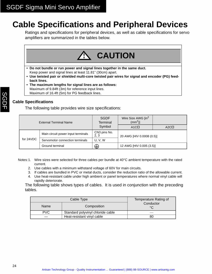
Cable Specifications and Peripheral DevicesRatings and specifications for peripheral devices, as well as cable specifications for servo amplifiers are summarized in the tables below.
Cable Specifications
The following table provides wire size specifications:
Notes:1. Wire sizes were selected for three cables per bundle at 40°C ambient temperature with the rated current.
2. Use cables with a minimum withstand voltage of 60V for main circuits.3. If cables are bundled in PVC or metal ducts, consider the reduction ratio of the allowable current.4. Use heat-resistant cable under high ambient or panel temperatures where normal vinyl cable will
rapidly deteriorate.The following table shows types of cables. It is used in conjunction with the preceding tables.
• Do not bundle or run power and signal lines together in the same duct.Keep power and signal lines at least 11.81” (30cm) apart.
• Use twisted pair or shielded multi-core twisted pair wires for signal and encoder (PG) feed-back lines.
• The maximum lengths for signal lines are as follows:Maximum of 9.84ft (3m) for reference input lines.Maximum of 16.4ft (5m) for PG feedback lines.
External Terminal NameSGDF
Terminal Symbol
Wire Size AWG [in2 (mm2)]
A1C# A2C#
for 24VDC
Main circuit power input terminals CN3 pins No. 2, 3 20 AWG [HIV 0.0008 (0.5)]
Servomotor connection terminals U, V, W
Ground terminal 12 AWG [HIV 0.005 (3.5)]
Cable Type Temperature Rating of Conductor
°CName Composition
PVC Standard polyvinyl chloride cable —— Heat-resistant vinyl cable 80
CAUTION!
Artisan Technology Group - Quality Instrumentation ... Guaranteed | (888) 88-SOURCE | www.artisantg.com

SGDF Sigma Mini Servo Amplifier
25
SG
DF
The following table specifies the appropriate cables for CN1 and CN2 servo amplifier connectors.
Wire sizes were selected with the expectation of three cables per bundle, at an ambient temperature of 40°C, at the rated current level.
Connector Name
Signal Description Specification
I/O Signal Connector CN1
Cable Use twisted pair or shielded twisted pair wire.Applicable wire 28AWGFinished cable Dimension Φ0.24in (Φ6.1mm) maximum
PG Signal Connector CN2
Cable Use Yaskawa cable, or shielded twisted pair wire.
Applicable wire
Use 22 AWG [0.0005 in2 (0.34mm2)] for the encoder power supply and 26 AWG [0.0002 in2 (0.14mm2)] for other signals. These conditions permit wiring dis-tances up to 16.4ft (5m).
Finished cable Dimension Φ0.3in (Φ7.5mm) maximum
Artisan Technology Group - Quality Instrumentation ... Guaranteed | (888) 88-SOURCE | www.artisantg.com

SGDF Sigma Mini Servo Amplifier
26
SG
DF
Peripheral Device Types and Capacities
Note: *Operating characteristics at 25°C: 200% for 2s minimum; 700% for 0.01s minimum.
Peripheral Device Manufacturers If the Nemic-Lambda noise filter is unavailable, please contact one of the other manufacturers to obtain a suitable substitute.
Main Circuit Power Supply
Model
Applicable Servomotor
Power Supply
Capacity per Servo
Amplifier(W)
MCCB or FuseCapacity
A*
RecommendedNoise Filter
Magnetic ContactorCapacity
(W)SGDF- Model Specifications
24VDC10 A1C# SGMM-A1S 27.6
5 MYB-1206-33(Nemic-Lambda)
Single-phase250VAC
6A
Contactor(30A) or equivalent20 A2C# SGMM-A2S 40.1
Nemic-Lambda: SchaeffnerLambda Electronics, Inc. 9b Fadem Rd.515 Broad Hollow Road Springfield, New Jersey 07081Melville, L.I., New York 11747-3700 Phone: (973) 379-7778Phone: (516) 694-4200 (800) 367-5566Fax: (516) 293-0519 Fax: (973) 379-1151Internet: www.lambda.com
Okaya Electronic America Tokin America, Inc.503 Wall Street 155 Nicholson LaneValparaiso, Indiana 46383 San Jose, California 95134Phone: (800) 852-0122 Phone: (408) 432-8020Fax: (219) 477-4856 Fax: (408) 432-0375Internet: [email protected] Internet: www.tokin.com
Artisan Technology Group - Quality Instrumentation ... Guaranteed | (888) 88-SOURCE | www.artisantg.com

Sigma Mini Servo System Product Catalog Supplement
G-MI#99002-SigmaMini Printed In U.S.A.Yaskawa Electric America, Inc. July, 1999
Yaskawa . . . A World of Automation Solutions
Yaskawa Electric America, Inc.Chicago-Corporate Headquarters
2121 Norman Drive SouthWaukegan, Illinois 60085
1-800-YASKAWA
http://www.yaskawa.com
Yaskawa Electric EuropeAm Kronberger Hang 2, 65824
Schwalbach, Germany49-6196-569-300
http://www.yaskawa.de
Yaskawa Electric CorporationNew Pier Takeshiba
South Tower, 1-16-1 KaiganMinatoku, Tokyo 105 Japan
81-3-5402-4511
http://www.yaskawa.co.jp
Artisan Technology Group - Quality Instrumentation ... Guaranteed | (888) 88-SOURCE | www.artisantg.com

Artisan Technology Group is your source for quality new and certified-used/pre-owned equipment
• FAST SHIPPING AND DELIVERY
• TENS OF THOUSANDS OF IN-STOCK ITEMS
• EQUIPMENT DEMOS
• HUNDREDS OF MANUFACTURERS SUPPORTED
• LEASING/MONTHLY RENTALS
• ITAR CERTIFIED SECURE ASSET SOLUTIONS
SERVICE CENTER REPAIRSExperienced engineers and technicians on staff at our full-service, in-house repair center
WE BUY USED EQUIPMENTSell your excess, underutilized, and idle used equipment We also offer credit for buy-backs and trade-inswww.artisantg.com/WeBuyEquipment
REMOTE INSPECTIONRemotely inspect equipment before purchasing with our interactive website at www.instraview.com
LOOKING FOR MORE INFORMATION? Visit us on the web at www.artisantg.com for more information on price quotations, drivers, technical specifications, manuals, and documentation
Contact us: (888) 88-SOURCE | [email protected] | www.artisantg.com
SMViewInstra