ardco/traverse lift, l.l.c. owner/operator manual...
TRANSCRIPT

Page 1
ARDCO/Traverse Lift, L.L.C. OWNER/OPERATOR MANUAL MODEL TL-8044
ROUGH TERRAINVARIABLE REACHFORKLIFT
OWNER/OPERATOR MANUAL
MODEL TL 8044

Page 2
ARDCO/Traverse Lift, L.L.C. OWNER/OPERATOR MANUAL MODEL TL-8044
TL 8044 FORKLIFT OWNER/OPERATOR MANUAL
Copyright 1997ARDCO/Traverse Lift, L.L.C.
Technical PublicationsHouston, TX
Page 3
ARDCO/Traverse Lift, L.L.C. OWNER/OPERATOR MANUAL MODEL TL-8044
(Continued on next page)
TL8044 Table of Contents
OWNER/OPERATOR MANUAL ..........................................................................................................1
INTRODUCTION .................................................................................................................................... 6PREFACE.................................................................................................................................................................. 7MATERIAL DATA SAFETY SHEETS ................................................................................................................... 8IDENTIFICATION NUMBERS ............................................................................................................................... 9AFTER DELIVERY CHECK ................................................................................................................................. 10
SAFETY .................................................................................................................................................. 11SAFETY RULES .................................................................................................................................................... 12
EXPLANATION OF WARNINGS .................................................................................................................. 12EXPLANATION OF CAUTIONS ................................................................................................................... 12EXPLANATION OF NOTES........................................................................................................................... 12BEFORE OPERATION .................................................................................................................................... 13MACHINE OPERATION ................................................................................................................................ 13TRANSPORTING SAFELY ............................................................................................................................ 14PARKING THE MACHINE ............................................................................................................................ 15BURN PREVENTION...................................................................................................................................... 15 FIRE OR EXPLOSION PREVENTION ......................................................................................................... 15MAINTENANCE ............................................................................................................................................. 16SAFETY DECALS ........................................................................................................................................... 17
EQUIPMENT ......................................................................................................................................... 21INTRODUCTION ................................................................................................................................................... 22
RIGHT, LEFT, FRONT AND REAR OF MACHINE ..................................................................................... 22SAFETY PRECAUTIONS ............................................................................................................................... 23IDENTIFICATION........................................................................................................................................... 24FORKLIFT IDENTIFICATION PLATE ......................................................................................................... 24ENGINE IDENTIFICATION PLATE ............................................................................................................. 25TRANSMISSION IDENTIFICATION PLATE ............................................................................................... 25AXLE IDENTIFICATION PLATE LOCATION ............................................................................................ 25
EQUIPMENT DESCRIPTION ............................................................................................................................... 26FORKLIFT DESCRIPTION............................................................................................................................. 26ENGINE DESCRIPTION ................................................................................................................................. 26AXLE DESCRIPTION ..................................................................................................................................... 26SPECIFICATIONS ........................................................................................................................................... 26TABLE 1. SPECIFICATIONS ......................................................................................................................... 26
OPERATION ......................................................................................................................................................... 29INTRODUCTION ................................................................................................................................................... 30
CONTROLS AND INDICATORS ................................................................................................................... 30TABLE II. CONTROLS AND INDICATORS ............................................................................................... 31
PREOPERATIONAL CHECKS AND SERVICES ................................................................................................ 32CHECK ENGINE OIL LEVEL ........................................................................................................................ 32CHECK ENGINE COOLANT LEVEL............................................................................................................ 33CHECK TRANSMISSION OIL ....................................................................................................................... 33CHECK FUEL LEVEL..................................................................................................................................... 34

Page 4
ARDCO/Traverse Lift, L.L.C. OWNER/OPERATOR MANUAL MODEL TL-8044
TABLE OF CONTENTS (Continued)
CHECK HYDRAULIC FLUID LEVEL .......................................................................................................... 34TIRES AND RIMS ........................................................................................................................................... 34INSPECTION FOR LEAKS ............................................................................................................................. 34GENERAL INSPECTION ................................................................................................................................ 34PARKING BRAKE TEST AND ADJUSTMENT ........................................................................................... 34
OPERATIONAL CHECKS AND SERVICES ....................................................................................................... 35GAUGES AND INDICATORS........................................................................................................................ 35HYDRAULIC FLUID LEVEL ......................................................................................................................... 35CHANGES ........................................................................................................................................................ 35
OPERATING INSTRUCTIONS ............................................................................................................................. 35STARTUP AND DRIVING ............................................................................................................................. 35QUICK DISCONNECT FEATURE ................................................................................................................. 38RAISING THE LOAD...................................................................................................................................... 38TRANSPORTING THE LOAD ....................................................................................................................... 39LANDING THE LOAD.................................................................................................................................... 40
MAINTENANCE .................................................................................................................................................... 41TABLE III. SCHEDULED MAINTENANCE ................................................................................................ 41TABLE IV. FLUIDS & LUBRICANTS ......................................................................................................... 43
TROUBLESHOOTING .......................................................................................................................................... 47HOW TO USE TROUBLESHOOTING TABLES .......................................................................................... 47TABLE V. ENGINE TROUBLESHOOTING ................................................................................................ 47TABLE VI. ENGINE ELECTRICAL TROUBLESHOOTING...................................................................... 51TABLE VII. TRANSMISSION TROUBLESHOOTING ............................................................................... 52TABLE VIII. HYDRAULIC SYSTEM TROUBLESHOOTING .................................................................... 52
ENGINE MAINTENANCE .................................................................................................................................... 53ENGINE OIL CHANGE................................................................................................................................... 53REPLACE FUEL FILTER ............................................................................................................................... 54BLEED FUEL SYSTEM .................................................................................................................................. 55THERMOSTAT REMOVAL AND INSTALLATION ................................................................................... 57THERMOSTAT TEST ..................................................................................................................................... 58DRIVE BELT ADJUSTMENT ........................................................................................................................ 58
ELECTRICAL SYSTEM MAINTENANCE .......................................................................................................... 59ALTERNATOR REPLACEMENT .................................................................................................................. 59BATTERY REPLACEMENT .......................................................................................................................... 60FUSE REPLACEMENT ................................................................................................................................... 61
TRANSMISSION MAINTENANCE ..................................................................................................................... 61TRANSMISSION OIL CHANGE .................................................................................................................... 61TRANSMISSION FILTER ELEMENT REPLACEMENT ............................................................................. 62
AXLE MAINTENANCE ........................................................................................................................................ 63AXLE LUBRICANT CHANGE....................................................................................................................... 63
HYDRAULIC SYSTEM MAINTENANCE........................................................................................................... 64HYDRAULIC STRAINER ELEMENT REPLACEMENT ............................................................................. 64HIGH PRESSURE HYDRAULIC FILTER ELEMENT REPLACEMENT ................................................... 65
BRAKE SYSTEM MAINTENANCE..................................................................................................................... 65PARKING BRAKE CABLE ADJUSTMENT .................................................................................................65
SUMMARY ............................................................................................................................................................ 66

Page 5
ARDCO/Traverse Lift, L.L.C. OWNER/OPERATOR MANUAL MODEL TL-8044
INT
RO
DU
CT
ION
Page 6
ARDCO/Traverse Lift, L.L.C. OWNER/OPERATOR MANUAL MODEL TL-8044
PREFACE
This manual instructs the owner/operator how to correctly operate the ARDCO/Traverse Lift Model TL8044forklift. The location and operation of all controls are explained in this manual. It also contains lubricationtables, which indicate the recommended servicing intervals for all fluids and greased components.
This manual should be considered a permanent part of your vehicle. It should stay with the vehicle, if sold, toprovide the next owner with required operating instructions.
All instructions, illustrations and specifications contained herein are based on upon the latest product informationavailable at the time of printing. Traverse Lift reserves the right to change specifications without notice in orderto follow its policy of constantly striving to manufacture a better product without incurring any liability toprovide these new features on any units previously manufactured.
Be sure your dealer has returned the Warranty Registration Form for your machine to ARDCO/Traverse Lift.This form must be filed out properly to initiate warranty coverage on the machine. In addition, your dealer willfill out a Machine Inspection Report, which the owner should sign. Also, a 30-day check up is recommended asdefined in this manual. If a problem occurs with your machine during the warranty period, contact your dealerimmediately. Do not continue to operate the machine until authorized.
Page 7
ARDCO/Traverse Lift, L.L.C. OWNER/OPERATOR MANUAL MODEL TL-8044
MATERIAL DATA SAFETY SHEETS
The Federal Occupational, Safety and Health Administration (OSHA) Standard 9 CFR 1910.1200 and, in somecases, state and local Right-To-Know laws, may require that specific Material Safety Data Sheets be available toemployees prior to operating this equipment. These sheets include information on substances contained in theequipment such as antifreeze, battery acid, diesel fuel, gasoline, engine oil, grease and hydraulic oil.
Upon written request, TRAVERSE LIFT will provide the Material Safety Data Sheets applicable to our productline at no extra cost. Write to:
ARDCO/Traverse Lift L.L.C.322 Riley Road
P.O. Box 451960Houston, TX 77245-1960
FAX: (713) 433-5655
Include the customer’s return address, machine model and machine serial number to ensure a prompt response.
Page 8
ARDCO/Traverse Lift, L.L.C. OWNER/OPERATOR MANUAL MODEL TL-8044
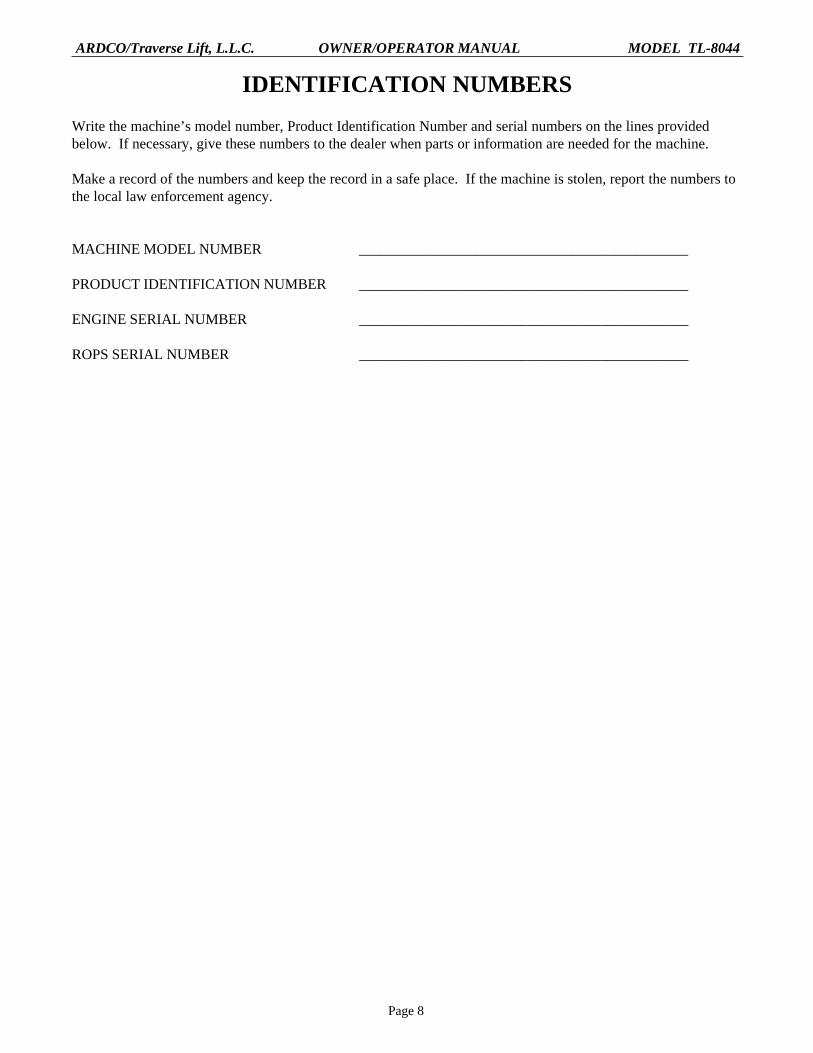
IDENTIFICATION NUMBERS
Write the machine’s model number, Product Identification Number and serial numbers on the lines providedbelow. If necessary, give these numbers to the dealer when parts or information are needed for the machine.
Make a record of the numbers and keep the record in a safe place. If the machine is stolen, report the numbers tothe local law enforcement agency.
MACHINE MODEL NUMBER _____________________________________________
PRODUCT IDENTIFICATION NUMBER _____________________________________________
ENGINE SERIAL NUMBER _____________________________________________
ROPS SERIAL NUMBER _____________________________________________

Page 9
ARDCO/Traverse Lift, L.L.C. OWNER/OPERATOR MANUAL MODEL TL-8044
AFTER DELIVERY CHECK
Two copies of the After Delivery Check are shipped loose with this manual. One copy is for the customer andone is for the dealer. Make sure the dealer performs the After Delivery Check following the first 30 hours ofmachine operation.
NOTE: The customer’s cost for this inspection will be for filters, oil or other accessories. If the dealer comes tothe machine, there may also be a cost for the time and travel.

Page 10
ARDCO/Traverse Lift, L.L.C. OWNER/OPERATOR MANUAL MODEL TL-8044
THIS PAGEINTENTIONALLY
LEFT BLANK
Page 11
ARDCO/Traverse Lift, L.L.C. OWNER/OPERATOR MANUAL MODEL TL-8044
SA
FE
TY

Page 12
ARDCO/Traverse Lift, L.L.C. OWNER/OPERATOR MANUAL MODEL TL-8044
SAFETY RULES
Most accidents involving machine operation and maintenance can be avoided by following basic rules andprecautions. Read and understand all the safety messages in this manual, and the safety signs on the machine,before operating or servicing the machine. Contact your dealer if you have any questions.
READ THIS MANUAL COMPLETELY and be sure to understand the characteristics of speed, stability, andsteering of this machine. DO NOT REMOVE THIS MANUAL OR THE SAFETY MANUAL FROM THEMACHINE. Contact your dealer for additional manuals. NOTE: The manual storage box is located inside thestorage compartment under the operator’s seat.
The safety information given in this manual does not replace safety codes, insurance regulations, or federal, state,and local laws. Be sure the machine has the correct equipment according to these rules or laws.
IMPORTANT: Safety messages in this section point out situations that can be encountered during the normaloperation and maintenance of your machine. These safety messages also give possible ways of dealing with theseconditions.
Additional safety messages are used in the text of the manual to show specific safety hazards.
EXPLANATION OF WARNINGS
A warning is a statement that informs the reader of a condition that is unsafe to personnel. Failure to heed awarning may result in DEATH or INJURY to personnel.
EXPLANATION OF CAUTIONS
Cautions are provided as statements that identify conditions and/or practices that could result in damage to theequipment.
EXPLANATION OF NOTES:
Notes are statements that simply provide additional information. Notes are not safety related.

Page 13
ARDCO/Traverse Lift, L.L.C. OWNER/OPERATOR MANUAL MODEL TL-8044
BEFORE OPERATION 1. Avoid loose fitting clothing, loose or uncovered long hair, jewelry or loose personal articles.
2. Different jobs will require different protective equipment. Items such as hard hats, protective shoes,heavy gloves, reflector-type vests, respirators and ear protection can be required. Know and use theequipment this is required before starting the job.
3. Be prepared for emergencies. Always have a first aid kit and a good, fully charged fire extinguisher onhand. Know how to use each.
4. Know the hand signals used on the job. Follow the instructions of the flag man, signs, etc.
5. Check that all guards and covers are installed correctly.
6. Foreign material or grease on the steps and hand rails can cause an accident. Keep the steps and handrails clean.
7. Before operating at night, check that all lamps illuminate.
8. Know the rules, laws, and safety equipment necessary for transporting this machine on road or highway.
9. Before starting the engine, walk around the machine and check for oil or fluid leaks. Replace all brokenor missing parts and do the required lubrication and maintenance as shown in this manual. Clean all trashand debris from the machine.
10. Always face the machine and use the hand rails and steps when getting one. Do not rush.
11. Remove all loose objects from the operator’s compartment and from the machine. Loose objects can jamcontrols and cause accidents.
12. Before starting the engine, always fasten the seat belt.
13. Engine exhaust fumes can cause death. If you operate this machine in an enclosed area, use goodventilation to replace the exhaust fumes with fresh air.
14. Make sure all persons are away from the machine and give a warning before starting the engine.
MACHINE OPERATION
1. Check all controls in a clear area and make sure the machine is operating correctly.
2. Do not allow other persons to ride on the machine. Other persons can fall or can cause an accident.
3. Dust, fog, smoke, etc., can decrease your vision and cause an accident. Stop the machine or decrease thespeed until everything can be seen.

Page 14
ARDCO/Traverse Lift, L.L.C. OWNER/OPERATOR MANUAL MODEL TL-8044
4. Contact with high voltage power lines, underground cables, etc., can cause serious injury or death fromelectrocution.
Before driving in an area with high voltage lines or cables, HAVE THE POWER DISCONNECTED ORKEEP A SAFE WORKING DISTANCE from the lines or cables. Know the safe working distance fromthe high voltage power equipment and observe federal, state/provincial, or local safety codes orregulations that apply to the job site.
5. Electrical cables, gas pipes, water pipes, sewers or other underground objects can cause injury or death.Learn the location of underground hazards before operating the machine in a new area. Contact all localutility companies to obtain information on their underground equipment in the work area.
6. If this machine rolls over, death or injury may occur. Determine if weather, road, or earth conditions willpermit safe operation on a hill, ramp or rough ground.
7. Stay away from hazardous areas such as ditches, overhangs, etc. Walk around the work area beforestarting and look for hazards.
8. Be alert and always know the location of all workers in the area. Keep all other persons completely awayfrom the machine. Injury or death can result if these instructions are not followed.
9. Operate the machine controls from the operator’s seat only.
10. Keep the forks low when moving around the work area and be careful when raising the load.
11. Before operating the equipment where visibility is reduced, such as next to a building, install safetymarkers to warn others of possible dangers.
TRANSPORTING SAFELY
NOTEWhen truck mounted, this machine is designed to be transported between localwork sites.
1. Know which warnings must be placed on machine for highway travel and whether an escort is needed.
2. Flag attachment or furthest projection of machine for safety.
3. Know measurements of machine when mounted on truck. Be sure machine is within proper limits forhighway transporting.
4. Become familiar with public laws and ordinances affecting driving on public roads with a mountedmachine. Check route for clearance. Check bridges for weight limits. Do not exceed clearances orweight limits.
5. Always shut down machine engine when transporting, even over short distances. Never ride on machinewhile transporting.
6. Do not put chains over or against hydraulic lines or hoses.
Page 15
ARDCO/Traverse Lift, L.L.C. OWNER/OPERATOR MANUAL MODEL TL-8044
7. Always use tape or cap exhaust pipe to prevent air from spinning tubrocharger while vehicle istransported at highway speeds. The turbochargers depend upon engine oil pressure to lubricate shaftbearings and may be damaged if spun dry. BE SURE TO REMOVE TAPE AFTER TRANSPORTINGOR BEFORE STARTING ENGINE.
PARKING THE MACHINE
1. When parking the machine and before leaving the operator’s seat, engage the parking brake.
2. Always face the machine and use the hand rail and step hen getting off. Do not rush and do not jumpfrom the machine.
BURN PREVENTION
1. Battery acid causes severe burns. Batteries contain sulfuric acid. Avoid contact with skin, eyes orclothing. Antidote- EXTERNAL: Flush with water. Antiodote-INTERNAL: Drink large quantities ofwater or milk. Follow with milk of magnesia, beaten egg or vegetable oil. Call a doctor immediately.Antidote-EYE: Flush with water for 15 minutes and get prompt medical attention.
2. If the battery electrolyte freezes, the battery may explode if (1) battery charge is attempted, or (2) andattempt is made to jump start the engine. To prevent the battery electrolyte from freezing, keep thebattery at full charge.
FIRE OR EXPLOSION PREVENTION
1. Sparks or flame can cause the hydrogen gas in a battery to explode. To prevent an explosion, whendisconnecting the battery cables, disconnect the negative (-) cable first. When connecting battery cables,connect the negative (-) cable last. When connecting jumper cables to start the engine, connect thenegative (-) cable last and disconnect the negative (-) cable first after the engine starts.
2. Do not short circuit the battery posts with metal items.
3. Do not weld, grind or smoke near a battery.
4. Sparks from the electrical system or engine exhaust can cause an explosion and fire. Before you operatethis machine in an area with flammable dust or vapors, use good ventilation to remove the flammabledust or vapors from the area.
5. Engine fuel can cause an explosion or fire. Do not fill the fuel tank with the engine running or near openflames or sparks.
6. Use nonflammable cleaning solvent to clean parts.
7. Fire can cause injury or death. Always have a good, fully charged fire extinguisher near or on themachine. Make sure the fire extinguisher is serviced according to the manufacturer’s instructions.
8. If a fire extinguisher has been used, always recharge or replace the fire extinguisher before operating themachine.

Page 16
ARDCO/Traverse Lift, L.L.C. OWNER/OPERATOR MANUAL MODEL TL-8044
9. Remove all trash or debris from the machine each day. Especially check the engine rea and exhaustsystem.
10. Starting fluid (ether) can cause injury or death. Do not inhale starting fluid vapors. Wear face protectionwhen removing or installing a starting fluid container or when using aerosol spray starting fluid. Usestarting fluid according to the instructions in this manual.
11. If the machine has an oil, fuel or hydraulic leak, always repair the leak and clean the area beforeoperating.
12. Keep the cooling system clean and maintain the correct coolant level.
13. Do not store oily rags or other flammable materials on the machine.
14. Check the electrical system for loose connections or frayed insulation. Repair or replace the loose ordamaged parts.
15. Before welding or using a torch on the machine, clean the area to be repaired.
MAINTENANCE
1. Before servicing the machine, put a “DO NOT OPERATE” tag on the instrument panel.
2. Improper service or repair can cause injury or death. Refer to the service manual for proper maintenanceprocedures.
3. Unauthorized modifications to this machine can cause injury or death. Do not make unauthorizedmodifications to this machine. Consult your authorized TRAVERSE LIFT dealer before modifying themachine.
4. For service with the engine running, have another person for help. Follow the instructions in this manualor the service manual. DO NOT LEAVE THE OPERATOR’S SEAT WITH THE ENGINE RUNNING.
5. Metal chips or debris can cause eye injury. Always wear eye or face protection when using a hammer onthis machine. Use a hammer with a soft face, such as brass, to drive hardened pins.
6. Hydraulic fluid or grease injected into skin can cause severe injury or death. Keep hands and body awayfrom any pressured leak. If fluid is injected into skin, see a doctor immediately.
7. When servicing this machine, always wear safety protection.

Page 17
ARDCO/Traverse Lift, L.L.C. OWNER/OPERATOR MANUAL MODEL TL-8044
SAFETY DECALS
Injury or death can result if safety decals are not followed. Replace any missing ordamaged safety decal and keep all safety decals clean. See a TRAVERSE LIFT dealer fornew safety decals.
1. Be sure to read all safety decals and all instruction decals. Check these decals daily.Keep these decals clean.
2. To clean the decals, use only a cloth, water and soap. Do not use solvents, gasoline, etc.
3. Replace damaged, missing, or unreadable decals. If a decal is on a part that is replaced,install a new decal on the new part.

Page 18
ARDCO/Traverse Lift, L.L.C. OWNER/OPERATOR MANUAL MODEL TL-8044
Injury or death can result if safety decals are not followed. Replace any missing ordamaged safety decal and keep all safety decals clean. See a TRAVERSE LIFT dealer fornew safety decals.
SAFETY DECALS (CON’T)

Page 19
ARDCO/Traverse Lift, L.L.C. OWNER/OPERATOR MANUAL MODEL TL-8044
Injury or death can result if safety decals are not followed. Replace any missing ordamaged safety decal and keep all safety decals clean. See a TRAVERSE LIFT dealer fornew safety decals.
SAFETY DECALS (CON’T)

Page 20
ARDCO/Traverse Lift, L.L.C. OWNER/OPERATOR MANUAL MODEL TL-8044
Injury or death can result if safety decals are not followed. Replace any missing ordamaged safety decal and keep all safety decals clean. See a TRAVERSE LIFT dealer fornew safety decals.
SAFETY DECALS (CON’T)

Page 21
ARDCO/Traverse Lift, L.L.C. OWNER/OPERATOR MANUAL MODEL TL-8044
EQ
UIP
ME
NT

Page 22
ARDCO/Traverse Lift, L.L.C. OWNER/OPERATOR MANUAL MODEL TL-8044
INTRODUCTION
All directional references (right, left, front and rear) used in this manual are as seen from the operator’s seat.
Figure 1. Directional Reference
The Model TL8044 rough-terrain, variable-reach forklift is manufactured by ARDCO/Traverse Lift, L.L.C., asubsidiary of Pettibone, L.L.C. The Model TL8044 is designed to provide years of reliable operation withminimal maintenance.
RIGHT, LEFT, FRONT AND REAR OF MACHINE

Page 23
ARDCO/Traverse Lift, L.L.C. OWNER/OPERATOR MANUAL MODEL TL-8044
SAFETY PRECAUTIONS
1. Read and fully understand the operator’s manual before attempting to operate the forklift.
2. Always pay attention to decals located on the forklift. Failure to do so can result in death, serious injuryand/or damage to equipment.
3. Only trained, qualified personnel should operate the forklift.
4. Under no circumstances are passengers allowed to ride on the forklift.
5. Always wear the seatbelt when operating the forklift.
6. Controls are to be operated only by the person seated in the operator’s compartment.
7. No personnel should ever walk or stand under a raised boom or walk alongside a moving forklift.
8. Do not operate the forklift near electrical power lines.
9. Do not use the forklift to lift personnel.
10. Raise the boom only if there is sufficient overhead clearance.
11. Make certain that the load is positioned squarely and evenly on both (or all) forks before raising.
12. Do not attempt to remove a load from the forks by stopping the forklift suddenly.
13. Do not attempt to raise or land loads that exceed the forklift’s capacity. Refer to the “SpecificationsTable” or the “Load Chart” located in the operator’s compartment.
14. Always pick up a load with consideration to its center of gravity. Position the load on the forksaccordingly.
15. Never land a load in such a way that it may topple. Always land the load squarely on a solid, levellanding area, never on an uneven surface. Stacking loads is not advisable; however, if stacking isunavoidable, exercise extreme caution.
16. Do not operate the forklift or handle loads in a reckless manner.
17. Position the load no high than eye level when transporting.
18. Always be aware of the machine and load width and the width of the path in which it is operating.
19. Make certain that the load is stable before transporting. Do not transport or lift loads that are obviouslyunsafe or questionable.
20. When driving, do not make any sudden stops or turns.
21. When possible, do not park the forklift on an incline. If parking on an incline is unavoidable, apply theparking brake and chock the wheels.

Page 24
ARDCO/Traverse Lift, L.L.C. OWNER/OPERATOR MANUAL MODEL TL-8044
22. Modifications to the forklift can result in death and/or serious injury to personnel, damage to equipmentand/or poor equipment performance.
23. When leaving the operator’s compartment, always lower the forks to the ground, apply the parking brake,stop the engine and turn off the key.
24. Prior to starting the forklift, warn all personnel in the area.
25. Always use the traverse feature to land a load rather than moving the forklift.
26. Do not operate a forklift that is in need of maintenance.
27. Do not operate the forklift in a closed building. Death or sickness from carbon monoxide poisoningcould result. Always operate in a well-ventilated area.
IDENTIFICATION
FORKLIFT IDENTIFICATION PLATE
The forklift identification plate is located outside, on the left end of a rear frame member of the operator’scompartment. It contains the equipment model number, serial number and gross vehicle weight (GVW). (SeeFigure 2.)
Figure 2. Forklift Identification Plate Location.

Page 25
ARDCO/Traverse Lift, L.L.C. OWNER/OPERATOR MANUAL MODEL TL-8044
ENGINE IDENTIFICATION PLATE
The engine identification plate is located on the engine block, above the starter. It contains the engine serialnumber.
TRANSMISSION IDENTIFICATION PLATE
The transmission identification plate is located atop the transmission housing, centered behind the engine. Itcontains the model, specification number and serial number.
Figure 3. Engine and Transmission Identification Plate Locations.
AXLE IDENTIFICATION PLATE LOCATION
The axle identification plate is located on the backside of the axle, to the right of the differential. The platecontains the axle part number, serial number and build date. The front axle is mounted with its backside towardthe front of the forklift.
Figure 4. Axle Identification Plate Location.

Page 26
ARDCO/Traverse Lift, L.L.C. OWNER/OPERATOR MANUAL MODEL TL-8044
EQUIPMENT DESCRIPTION
FORKLIFT DESCRIPTION
The Model TL8044 is a rough-terrain, variable-reach forklift with a gross vehicle weight of 25,290 pounds and alifting capacity of 8,000 pounds with carriage and boom retracted and 1500 pounds with carriage forward andboom extended. The forklift is equipped with four-wheel/two wheel-drive as selected by the operator. Thesteering system allows selection two-wheel steering, four-wheel steering or oblique (crab) steering.
ENGINE DESCRIPTION
The Model TL8044 forklift is equipped with a turbocharged, four cylinder, four cycle, liquid cooled, model4039T John Deere engine. This engine has a displacement of 239 cubic inches (2.9 L), a compression ratio of18.8:1 and has an output rating of 110 hp.
AXLE DESCRIPTION
The forklift is equipped with two model PS-1350 steerable drive axle, manufactured by Dana Spicer. Both axlesare equipped with internal, wet-type disc brakes, located inside the planetaries.
SPECIFICATIONS
Table 1 provides specifications for the various systems and major components of the Model TL8044 forklift. Allspecifications reflect the equipment configurations and characteristics as they were at the time of this publication.
TABLE 1. SPECIFICATIONS
MODEL TL8044 FORKLIFT
Lifting capacity 8,000 lbs. (3629 kg) with boom & carriage retracted.1,500 lbs. (680 kg) with carriage forward and boomextended.
Maximum forward reach 28 ft. (8.53 m)
Maximum lift height 37 ft. (11.28 m)
Gross Vehicle Weight (GVW) 25,950 lbs. (11,770 kg)
Maximum travel speed 20 mph (29.8 km/h)
Height 8 ft. 11 in. (2.72 m) with forks on ground
Length 23 ft. 6 in. (7.16 m) with carriage retracted and42 in. (1.06 m) forks
Width 8 ft. (2.44 m)
Ground clearance 17 in. (0.43 m)

Page 27
ARDCO/Traverse Lift, L.L.C. OWNER/OPERATOR MANUAL MODEL TL-8044
ENGINE John Deere Model 4039T, four cylinder, liquid cooled,turbocharged diesel with fuel injection.
Horsepower rating 110 hp
Displacement 239 cu. in.
Compression ratio 17.8:1
Oil capacity 10 qt. (9.46 L)
TRANSMISSION Funk Model 1700
Speeds 4 forward, 4 reverse
AXLES Dana Spicer Model PS-1350 steerable
TIRES 13:00 x 24 (8 ply), interchangeable
WHEELS 8.00 x 24, interchangeable
BRAKE SYSTEM Hydraulic, enclosed wet disc with mechanicalexternal disc parking brake.
ELECTRICAL SYSTEM 12 volt, negative ground
Alternator Delco-Remy, 12 volt, 78 amps with internalvoltage regulator
Battery 12 volt
Circuit protection: Instrument panel and horn Fuse, 15 amp Fuel injection pump Fuse, 10 amp Backup alarm and hourmeter Fuse, 15 amp Parking brake & low brake pressure alarm Fuse, 10 amp Joysticks Fuse, 10 amp Front axle lock switch Fuse, 10 amp
HYDRAULIC SYSTEM
Capacity 40 gal. (151.4 L)
Operating pressure 2800 psi (19306 kPa)
Pump Double gear type, transmission mounted
Filtration 25 micron suction filter, high pressure filter and100 micron return line strainer
TABLE I. SPECIFICATIONS (CON’T)
Page 28
ARDCO/Traverse Lift, L.L.C. OWNER/OPERATOR MANUAL MODEL TL-8044
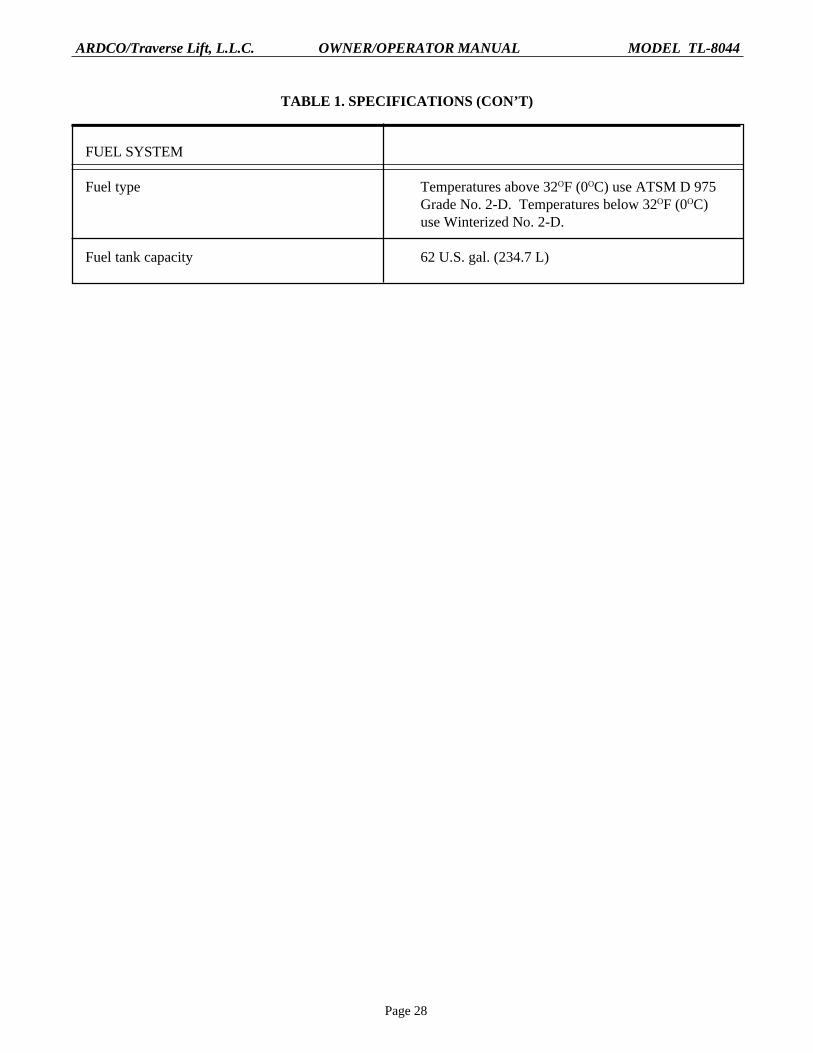
FUEL SYSTEM
Fuel type Temperatures above 32OF (0OC) use ATSM D 975Grade No. 2-D. Temperatures below 32OF (0OC)use Winterized No. 2-D.
Fuel tank capacity 62 U.S. gal. (234.7 L)
TABLE 1. SPECIFICATIONS (CON’T)
Page 29
ARDCO/Traverse Lift, L.L.C. OWNER/OPERATOR MANUAL MODEL TL-8044
OP
ER
AT
ION

Page 30
ARDCO/Traverse Lift, L.L.C. OWNER/OPERATOR MANUAL MODEL TL-8044
INTRODUCTION
WARNINGCarefully study and understand all the safety information provided in the SafetySummary, located at the front of this publication, prior to operating the forklift.
Prior to attempting to operate the forklift, read this publication and become familiar with all the safetyinformation (see warning), control and indicators, daily checks and services, and operating instructions provided.
CONTROLS AND INDICATORS
The following table consists of a list of all controls and indicators provided on the Model TL8044 forklift. Thetable is divided into two columns: ITEM/DESCRIPTION and FUNCTION. The first column gives the numberby which the particular control of indicator is identified in Figure 5 , “Controls and Indicators” as well as adescription of the component. The second column describes the component’s function.
Figure 5. Controls and Indicators

Page 31
ARDCO/Traverse Lift, L.L.C. OWNER/OPERATOR MANUAL MODEL TL-8044
TABLE II. CONTROLS AND INDICATORS
ITEM / DESCRIPTION FUNCTION
1. Steering wheel Used to control direction of travel
2. Horn button Sounds horn when pressed
3. Fork Tilt/Traverse Carriage joystick Used to tilt forks and level frame (by sing rockerswitch located atop joystick) to traverse the carriage.
4. Parking brake lever Use to apply the parking brake
5. Boom control and boom extend joystick Used to control boom extension and elevation andfor side tilt of the machine frame (by using rockerswitch located atop joystick
6. Steering selector Used to select either OBLIQUE, 2 WHEEL STEERor 4 WHEEL STEER
7. Accelerator pedal Used to control vehicle speed
8. Brake pedal Used to slow or halt forklift travel
9. Forward and Reverse shift lever Used to select either forward (F) or reverse(R) travel
10. Gear shift lever Used to select one of the four gear ranges
11. Fuel level gauge Shows fuel level when ignition switch is on
12. Engine oil pressure gauge Indicates engine oil pressure when engineis running
13. Battery alternator voltage gauge Indicates electrical system voltage when theengine is running
14. Water temperature gauge Indicates engine coolant temperature
15. Transmission oil temperature gauge Indicates transmission oil temperature
16. Frame leveling indicator Indicates angle of frame
17. Hourmeter Indicates total hours of engine operation
18. Brake fluid low pressure warning light Glows red and sounds audible alarm to warn oflow pressure in the brake system
19. Parking brake warning light Glows red and sounds audible alarm whenengine is running and parking brake is applied

Page 32
ARDCO/Traverse Lift, L.L.C. OWNER/OPERATOR MANUAL MODEL TL-8044
ITEM / DESCRIPTION FUNCTION
20. Ignition switch Used to start and stop engine and electricalsystem operation
21. Front axle positive traction button Engages front axle positive traction when pressed
22. Rear axle disconnect lever Used to remove torque from rear axle, allowingfront wheel drive only
23. Hydraulic fluid sightglass* Shows hydraulic fluid level & temperature
24. Boom extension indicator* Shows length of boom extension
25. Boom level indicator Indicates angle of boom in relation to horizontal
* Not shown
TABLE II. CONTROLS AND INDICATORS (CON’T)
PREOPERATIONAL CHECKS AND SERVICES
The following checks and services are to be performed before operating the forklift:
CHECK ENGINE OIL LEVEL
1. With engine off, pull the engine oil dipstick from the engine and wipe it clean.
2. Insert the dipstick back into its position in the engine block and withdraw it again.
3. Check the level of the oil on the dipstick and add oil as required.
ENGINE OIL DIPSTICK
Figure 6. Engine Oil Dipstick

Page 33
ARDCO/Traverse Lift, L.L.C. OWNER/OPERATOR MANUAL MODEL TL-8044
CHECK ENGINE COOLANT LEVEL
WARNINGNever attempt to remove a radiator cap from a hot engine. Pressurized steamand hot coolant escaping from the system can cause serious burns and injuries tothe eyes and skin.
1. After making certain the engine is cool, remove the radiator cap by pressing down while turning itcounterclockwise.
2. Look into the radiator filler neck to check the coolant level. The proper level is approximately 3/4 inchbelow the bottom of the radiator filler neck. Add coolant as needed.
3. Replace the radiator cap by pressing down while turning it clockwise.
Figure 7. Radiator Coolant Level Check.
3/4 INCH
CHECK TRANSMISSION OIL
1. Start the engine and allow it to idle with the transmission in neutral until the transmission reachesoperating temperature.
2. Remove the transmission dipstick and check the oil level on the dipstick.
3. Using a wrench, remove the breather, add transmission oil as needed and insert the dipstick back into thetransmission. Install the breather.
Figure 8. Transmission Fluid Dipstick

Page 34
ARDCO/Traverse Lift, L.L.C. OWNER/OPERATOR MANUAL MODEL TL-8044
CHECK FUEL LEVEL
Check the fuel level as indicated on the fuel gauge. Add fuel if necessary.
CHECK HYDRAULIC FLUID LEVEL
Check the hydraulic fluid level as indicated on the sightglass, located on the side of the hydraulic tank. Addhydraulic oil as needed.
TIRES AND RIMS
Inspect the tires for punctures, wear and, if applicable, proper tire pressure. Check the rims for missing lug nutsand wheel studs.
INSPECTION FOR LEAKS
Visually inspect the area beneath the forklift for puddles, which would indicate a leak. Locate the cause of theleak and correct the problem before operating the forklift. Recheck all fluid levels at this point.
GENERAL INSPECTION
Perform a walk-around inspection of the forklift, locking for loose items (tools, shop towels, etc.) that may havebeen left on the forklift. Remove any such items.
PARKING BRAKE TEST AND ADJUSTMENT
Prior to forklift operation, start the engine with the parking brake applied and put the transmission in gear withthe engine idling only. DO NOT rev the engine. If the parking brake does not hold, put the transmission inneutral, release the parking brake and make the adjustment by turning (clockwise) the knob located at the top ofthe parking brake handle. Reapply the parking brake, put the transmission in gear and test again.
Figure 9. Parking Brake Lever.
OFF
ON
ADJUSTMENTKNOB

Page 35
ARDCO/Traverse Lift, L.L.C. OWNER/OPERATOR MANUAL MODEL TL-8044
OPERATIONAL CHECKS AND SERVICESThe following checks and services are to be performed during forklift operation:
GAUGES AND INDICATORS
Observe all gauges and indicators and be prepared to halt operation in the event of any abnormal indication. Beconstantly aware of the fuel level, engine coolant temperature, transmission oil temperature and electrical systemvoltage.
HYDRAULIC FLUID LEVEL
Periodically check the hydraulic oil level and temperature as needed on the sightglass, which is located on theside of the hydraulic tank. Add hydraulic oil if necessary.
CHANGES
Be constantly alert to changes in the equipment’s operating characteristics. Such changes in performance aresometimes an indication of a malfunction.
OPERATING INSTRUCTIONS
STARTUP AND DRIVING
CAUTIONNever operate the starter for more than 20 seconds continuously. Allow 2minutes between starting efforts. If using starting fluid for a cold-weather start,inject the starting fluid only while the engine is cranking.
1. Start the engine by applying the parking brake, placing the transmission in neutral, inserting the ignitionkey into the switch and turning the key clockwise. Release the key when the engine starts.
WARNINGThe forklift must be standing still when selecting the steering mode. Death,serious injury and/or equipment damage could occur if the mode is selectedwhile the forklift is moving.
2. Determine which of the following steering modes is to be selected:
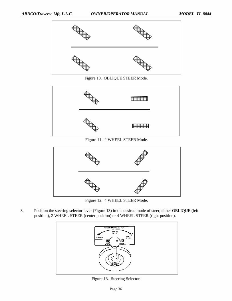
a. OBLIQUE. Shown in Figure 10. In this position, all four wheels will turn in the same direction.This steering mode should not be used at speeds exceeding 2 mph.
b. 2 WHEEL STEER. Shown in Figure 11. In this position, only the front wheels will steer.Before selecting this mode, the rear wheels must be turned straight using the 4 WHEEL STEERmode. Use ONLY 2 WHEEL STEER mode when travel speed exceeds 10 mph.
c. 4 WHEEL STEER. Shown in Figure 12. In this mode, the rear wheels will turn in the oppositedirection from the front wheels, providing the shortest turn radius. Do not use 4 WHEEL STEERat speeds over 10 mph.
Page 36
ARDCO/Traverse Lift, L.L.C. OWNER/OPERATOR MANUAL MODEL TL-8044
12345678901123456789011234567890112345678901123456789011234567890112345678901123456789011234567890112345678901
12345678901123456789011234567890112345678901123456789011234567890112345678901123456789011234567890112345678901
123456789012123456789012123456789012123456789012
123456789012123456789012123456789012123456789012
12345678901123456789011234567890112345678901123456789011234567890112345678901123456789011234567890112345678901
123456789012345678901234567890123456789012345678901234567890123456789012345678901234567890123456789012345678901234567890
12345678901123456789011234567890112345678901123456789011234567890112345678901123456789011234567890112345678901
12345678901234567890123456789012345678901234567890123456789012345678901234567890123456789012345678901234567890
Figure 10. OBLIQUE STEER Mode.
Figure 11. 2 WHEEL STEER Mode.
Figure 12. 4 WHEEL STEER Mode.
123456789012312345678901231234567890123123456789012312345678901231234567890123123456789012312345678901231234567890123123456789012312345678901231234567890123
123456789012312345678901231234567890123123456789012312345678901231234567890123123456789012312345678901231234567890123123456789012312345678901231234567890123
123456789012312345678901231234567890123123456789012312345678901231234567890123123456789012312345678901231234567890123123456789012312345678901231234567890123
123456789012312345678901231234567890123123456789012312345678901231234567890123123456789012312345678901231234567890123123456789012312345678901231234567890123
3. Position the steering selector lever (Figure 13) in the desired mode of steer, either OBLIQUE (leftposition), 2 WHEEL STEER (center position) or 4 WHEEL STEER (right position).
Figure 13. Steering Selector.

Page 37
ARDCO/Traverse Lift, L.L.C. OWNER/OPERATOR MANUAL MODEL TL-8044
4. Raise the forks to a safe travel height by pulling the boom control joystick to the rear until a safe height isreached.
5. Hold the brake pedal down and select either forward (F) or reverse (R) travel, using the forward andreverse gear shift lever. While continuing to hold the brake pedal down, select either 1 for first gear, 2for second gear, 3 for third gear or 4 for fourth gear, using the gear shift lever. (See Figure 14.)
6. Make certain that the area around the forklift is clear. Continue to hold the brake pedal down and releasethe parking brake.
WARNINGThe Model TL8044 forklift is capable of a maximum speed of 20 mph regardlessof direction. Make certain the intended direction has been selected beforereleasing the brake. Death, serious injury or damage to the equipment couldresult from acceleration in an unintended direction.
7. The forklift is now ready to drive by carefully releasing the brake pedal.
Figure 14. Startup and Driving.
Page 38
ARDCO/Traverse Lift, L.L.C. OWNER/OPERATOR MANUAL MODEL TL-8044
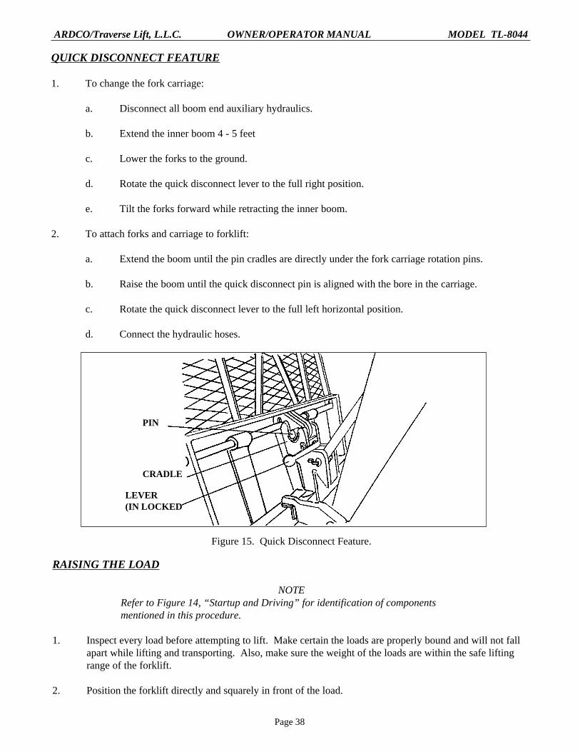
QUICK DISCONNECT FEATURE
1. To change the fork carriage:
a. Disconnect all boom end auxiliary hydraulics.
b. Extend the inner boom 4 - 5 feet
c. Lower the forks to the ground.
d. Rotate the quick disconnect lever to the full right position.
e. Tilt the forks forward while retracting the inner boom.
2. To attach forks and carriage to forklift:
a. Extend the boom until the pin cradles are directly under the fork carriage rotation pins.
b. Raise the boom until the quick disconnect pin is aligned with the bore in the carriage.
c. Rotate the quick disconnect lever to the full left horizontal position.
d. Connect the hydraulic hoses.
Figure 15. Quick Disconnect Feature.
RAISING THE LOAD
NOTERefer to Figure 14, “Startup and Driving” for identification of componentsmentioned in this procedure.
1. Inspect every load before attempting to lift. Make certain the loads are properly bound and will not fallapart while lifting and transporting. Also, make sure the weight of the loads are within the safe liftingrange of the forklift.
2. Position the forklift directly and squarely in front of the load.
PIN
CRADLE
LEVER(IN LOCKED

Page 39
ARDCO/Traverse Lift, L.L.C. OWNER/OPERATOR MANUAL MODEL TL-8044
3. Lower the boom by pushing the boom control joystick forward until the forks are at the necessary level toengage the load.
4. Level the forks by moving the Tilt/Traverse joystick forward (to tilt forward) or back (to tilt the forksback).
5. If necessary, adjust the width of the forks to accommodate the load.
6. Traverse slowly forward by pushing the Tilt/Traverse joystick to the right until the load is fully engagedand touching the backrest of the fork carriage.
7. To position the load for transport, tilt the forks back by pulling the Tilt/Traverse joystick back. Retractthe boom by moving the Boom Control joystick to the left and retract the carriage by moving the Tilt/Traverse joystick to the left.
8. Pull the Boom Control joystick back to lift the load only enough to clear obstacles. Keep the top of theload below eye level. The load is now ready to transport.
TRANSPORTING THE LOAD
NOTERefer to Figure 14, “Startup and Driving” for identification of componentsmentioned in this procedure.
1. Make certain that all the steps outlined in “STARTUP AND DRIVING” have been performed.
2. Always observe the path ahead and be aware of anything to the sides of the path that may pose a problemand act accordingly. DO NOT OVERDRIVE THE CONDITIONS.
3. Be constantly aware of the area overhead and make sure, before entering an area with limited overhead,that the forklift will fit. NEVER OPERATE NEAR POWER LINES.
4. Keep the load as close to the ground as possible when moving and DO NOT STOP SUDDENLY.Approach turns, uneven and/or slippery surfaces slowly. Sound horn and drive slowly in congested areas.
WARNINGNever attempt to drive across an excessively steep incline, regardless ofcircumstances. Serious injury and/or death could otherwise result. EXERCISEGOOD JUDGEMENT.
5. Driving on inclines or unstable surfaces is unsafe but sometimes unavoidable. If driving on an inclinecannot be avoided, level the forklift by using the rocker switch located on top of the Tilt/Traversejoystick as follows:
a. Press the left side of the rocker switch to tilt the forklift frame to the left.
b. Press the right side of the rocker switch to tilt the forklift frame to the right.
6. When traveling on inclines, do so as follows:
a. If transporting a load, approach the incline with the forks pointed uphill.

Page 40
ARDCO/Traverse Lift, L.L.C. OWNER/OPERATOR MANUAL MODEL TL-8044
b. If empty, approach the incline with the forks pointed downhill.
c. Do not approach an incline at an angle. When necessary to travel on an incline, drive eitherstraight up the incline or straight down.
LANDING THE LOAD
WARNINGWhen landing a load, be constantly aware of all personnel in the area. Sound thehorn as a warning to others. Make certain that all personnel in the area are farenough away to avoid injury should the load fall.
NOTERefer to Figure 14, “Startup and Driving”, for identification of componentsmentioned in this procedure.
1. Keeping the load low, position the forklift as close to the landing point as possible. DO NOT raise theload if the forks re tilted to one side. Level the machine, using the rocker switch located atop the Tilt/Traverse joystick before raising the load.
2. Raise the load to the proper height by pulling back on the Boom Control joystick.
3. Move the Tilt/Traverse joystick to the right to extend the carriage until the load is positioned directlyover the landing location.
4. Carefully lower the load by slowly pushing the Boom Control joystick forward until the load rests solidlyon the landing location. Continue to lower the boom until the forks have no weight in them.
5. By moving the Tilt/Traverse joystick forward or back as necessary, tilt the forks so that they are notcontacting the load or the landing area beneath them.
6. Move the Tilt/Traverse joystick to the left to traverse back and to move the forks away from the load.
SHUTDOWN
1. Bring the forklift to a complete stop and apply the parking brake.
2. Lower the forks to the ground by moving the Boom Control joystick forward.
3. Place the transmission in neutral.
4. Allow the engine to idle for 1-3 minutes.
5. Shut the engine off.
6. Cycle the hydraulic controls to relieve pressure.
7. Remove the ignition key from the switch.
8. Block wheels if on an incline.

Page 41
ARDCO/Traverse Lift, L.L.C. OWNER/OPERATOR MANUAL MODEL TL-8044
MAINTENANCE
The information provided on the following pages will allow the owner to establish an effective preventivemaintenance plan. Close adherence to such a plan will add greatly to the equipment’s performance and longevity.Always keep an accurate record of the maintenance performed.
The maintenance procedures included in the following are those that can be accomplished by the owner, usingcommon hand tools. For more complex maintenance, contact an authorized dealer or service representative.
TABLE III. SCHEDULED MAINTENANCE
SERVICE Daily 20 hr. 40 hr. 50 hr. 100 hr. 200 hr. 500 hr. 1000 hr. 2000 hr.
Engine Oil C *CR CR
Engine Oil Filter *CR CR
Fuel Filter CR
Engine Vent Tube Clean
Alternator Belt Adjust
Trans. Fluid C *CR CR
Trans. Filter *CR CR
Hydraulic Fluid C CR
Hydraulic Filter CR
Air Cleaner Element Clean
Radiator Coolant C
Battery C
Parking Brake Adjust
Axle Diff. *CR

Page 42
ARDCO/Traverse Lift, L.L.C. OWNER/OPERATOR MANUAL MODEL TL-8044
SERVICE Daily 20 hr. 40 hr. 50 hr. 100 hr. 200 hr. 500 hr. 1000 hr. 2000 hr.
Boom Pivot Lube
Front Tilt Cyl. Pivots Lube
Rear Tilt Cyl. Pivots Lube
Quick Attach Lube Pivots
Boom Rollers Lube
Frame Tilt Cylinder Lube
Axle U-Joints Lube
Steer Cyl. Pivots Lube
Steer Spindles Lube
Tie Rod End Pivots Lube
Drive Shaft Lube U-Joints
Planetary Hubs *CR C CR
TABLE III. SCHEDULED MAINTENANCE (CON’T)
C = Check fluid levels and add fluid as necessary * = First hours of operation CR = Change fluid or replace filter

Page 43
ARDCO/Traverse Lift, L.L.C. OWNER/OPERATOR MANUAL MODEL TL-8044
TABLE IV. FLUIDS & LUBRICANTS
APPLICATION DESCRIPTION
ENGINE OIL API Service Classification CE or CD(Single Grade) CCMC Specification D5 or D4
At temperatures:Below -4oF (-20oC) Artic Oil
-4oF (-20oC) to 50oF (10oC) SAE 10W
32oF (0oC) to 86oF (30oC) SAE 30W
50oF (10oC) to 104oF (40oC) SAE 40W
ENGINE OIL API Service Classification CE or CD(Multi-Grade) CCMC Specification D5 or D4
At Temperatures:-22oF (-30oC) to 68oF (20oC) SAE 5W-30
-4oF (-20oC) to 86oF (30oC) SAE 10W-30
14oF (-10oC) to 122oF (50oC) SAE 15W-40
ENGINE COOLANT John Deere Low Silicate Antifreeze or equivalent
TRANSMISSION FLUID The following hydraulic transmission fluids, asapplicable:
At Temperatures:Above -10oF (-23oC) Type C-3 (except Grade 30)
Below -10oF (-23oC) Type C-3 (except Grade 30) with auxiliary preheat toraise temperature to above -10oF (-23oC)
Above 32oF (0oC) Type C-3 or Type C-3 Grade 30

Page 44
ARDCO/Traverse Lift, L.L.C. OWNER/OPERATOR MANUAL MODEL TL-8044
APPLICATION DESCRIPTION
AXLE LUBRICANT Multi-purpose gear lubricants meeting MIL Spec(Single Grade) L-2105C and suitable for API Service Classification
GL-5
At Temperatures:-40oF (-40oC) to 32oF (0oC) SAE 75W
-15oF (-26oC) to 70oF (21oC) SAE 80W
10oF (-12oC) to 100oF (38oC) SAE 90W
40oF (4oC) and higher SAE 140W
AXLE LUBRICANT Multipurpose lubricants meeting MIL Spec(Multi-Grade) L-2105C and suitable for API Service Classification
GL-5
At Temperatures:-40oF (-40oC) to 100oF (38oC) SAE 75W-90
-40oF (-40oC) to 120oF (50oC) SAE 75W-140
-15oF (-26oC) to 100oF (38oC) SAE 80W-90
-15oF (-26oC) to 100oF (38oC) SAE 80W-90
10oF (-12oC) to 120oF) 50oC) SAE 85-140
GREASE ZERKS NLGI-2
HYDRAULIC FLUID ISO-32
LUBRICATIONAll grease fittings on the Model TL8044 are to be serviced with NLGI-2 grease at the intervals specified on TableIII. “Scheduled Maintenance.” Locations of the various grease zerks may be determined by use of theillustrations (Figures 16-19) provided on the following pages.
TABLE IV. FLUIDS AND LUBRICANTS (CON’T)

Page 45
ARDCO/Traverse Lift, L.L.C. OWNER/OPERATOR MANUAL MODEL TL-8044
Figure 16. Lubrication Points (Left Side and Axles).
Figure 17. Lubrication Points (Right Side).

Page 46
ARDCO/Traverse Lift, L.L.C. OWNER/OPERATOR MANUAL MODEL TL-8044
Figure 18. Lubrication Points (Front View).
Figure 19. Lubrication Points (Rear View)

Page 47
ARDCO/Traverse Lift, L.L.C. OWNER/OPERATOR MANUAL MODEL TL-8044
TROUBLESHOOTINGThe troubleshooting tables identify some of the most common problems occurring in forklifts and their possiblecauses. If, after following the recommendations provided, the problem is still present, contact an authorizeddealer or service representative.
HOW TO USE TROUBLESHOOTING TABLES
Locate the symptom in the “SYMPTOM” column of the table. Move across the page to the next column,“PROBLEM”. This column will give the most probable cause(s) of the malfunction. The “SOLUTION” columnwill provide the necessary maintenance action to correct the problem. If the problem cannot be solved by usingthe troubleshooting tables, contact an authorized dealer or service representative.
TABLE V. ENGINE TROUBLESHOOTING
SYMPTOM PROBLEM SOLUTION
Engine hard to start of will not start Improper starting procedure Review starting procedure
No fuel Check fuel level
Air in fuel line Bleed fuel line
Cold weather Use cold weather starting aids
Slow starter speed See “Starter Cranks Slowly”
Crankcase oil too heavy Use proper viscosity oil
Improper type of fuel Consult fuel supplier; use propertype fuel for conditions
Water, dirt or air in fuel Drain, flush, fill and bleed systemsystem
Clogged fuel filter Replace filter element
Dirty or faulty injection Have authorized dealer ornozzles engine distributor check injectors
Injection pump shut-off Turn key switch to “OFF” thennot reset to “ON”
Engine knocks Low engine oil level Add oil to engine crankcase
Injection pump out of time See authorized dealer orengine distributor
Low coolant temperature Check thermostat
Engine overheating See “Engine Overheats”

Page 48
ARDCO/Traverse Lift, L.L.C. OWNER/OPERATOR MANUAL MODEL TL-8044
SYMPTOM PROBLEM SOLUTION
Engine runs irregularly or Low coolant temperature Check thermostatstalls frequently
Clogged fuel filter Replace filter element
Water, dirt or air in fuel Drain, flush, fill and bleed systemsystem
Dirty or faulty injection Have authorized dealer or enginenozzles distributor check injectors
Below normal engine temperature Defective thermostat Check thermostat
Defective temperature gauge Check gauge, sender andor sender connections
Lack of power Engine overload Reduce load
Air intake restriction Service air cleaner
Clogged fuel filter Replace filter element
Improper type of fuel Use proper fuel
Overheated engine See “Engine Overheats”
Low engine temperature Check thermostat
Improper valve clearance See authorized service dealeror engine distributor
Dirty or faulty injection Have authorized service dealer ornozzles engine distributor check injectors
Injection pump out of time See authorized service dealer orengine distributor
Leaking exhaust manifold See authorized service dealer orgasket engine distributor
Defective aneroid control See authorized service dealer orline engine distributor
Restricted fuel hose Clean or replace fuel hose
Low fast idle speed See authorized service dealer orengine distributor
TABLE V. ENGINE TROUBLESHOOTING (CON’T)

Page 49
ARDCO/Traverse Lift, L.L.C. OWNER/OPERATOR MANUAL MODEL TL-8044
SYMPTOM PROBLEM SOLUTION
Low engine oil pressure Low oil level Add oil
Improper type oil Drain, then fill crankcase with oilof proper viscosity and quality
Clogged inlet screen on See authorized service dealer oroil pump pickup tube engine distributor
Faulty oil pump See authorized service dealer orengine distributor
High oil consumption Crankcase oil too light Use proper viscosity oil
Oil leaks Check for leaks in lines, gasketsand oil drain plug
Restricted crankcase vent Clean vent tubetube
Engine emits white smoke Improper type of fuel Use proper fuel
Low engine temperature Warm up engine to normaloperating temperature
Defective thermostat Check thermostat
Defective injection nozzles See authorized service dealer orengine distributor
Engine out of time See authorized service dealer orengine distributor
Engine emits black or gray Improper type of fuel Use proper fuelexhaust smoke
Clogged or dirty air cleaner Service air cleaner
Engine overloaded Reduce load
Injection nozzles dirty See authorized service dealeror engine distributor
Engine out of time See authorized service dealer orengine distributor
Engine overheats Engine overloaded Reduce load
Faulty radiator cap Have serviceman check
TABLE V. ENGINE TROUBLESHOOTING (CON’T)

Page 50
ARDCO/Traverse Lift, L.L.C. OWNER/OPERATOR MANUAL MODEL TL-8044
SYMPTOM PROBLEM SOLUTION
Engine overheats (con’t) Low coolant level Fill radiator, check radiator andhoses for loose connections orleaks
Loose or defective fan belt Adjust belt tension; replace asrequired
Low engine oil level Check oil level; add oil as required
Cooling system needs Flush cooling systemflushing
Defective thermostat Remove and check thermostat
Defective temperature Check coolant temperature with agauge or sender thermometer and replace gauge or
sender as necessary
Incorrect grade of fuel Use correct grade of fuel
High fuel consumption Improper type of fuel Use proper type of fuel
Clogged or dirty air cleaner Service air cleaner
Engine overloaded Reduce load
Improper valve clearance See authorized service dealer orengine distributor
Injection nozzles dirty See authorized service dealer orengine distributor
Engine out of time See authorized service dealer orengine distributor
Low engine temperature Check thermostat
TABLE V. ENGINE TROUBLESHOOTING (CON’T)

Page 51
ARDCO/Traverse Lift, L.L.C. OWNER/OPERATOR MANUAL MODEL TL-8044
TABLE VI. ENGINE ELECTRICAL TROUBLESHOOTING
SYMPTOM PROBLEM SOLUTION
Undercharged system Excessive electrical load Remove accessories or installfrom added accessories higher output alternator
Excessive engine idling Increase engine rpm whenusing heavy electrical load
Poor electrical connections Inspect and clean as necessaryon battery, ground strap,starter or alternator
Defective battery Test battery and replace asrequired
Defective alternator Test charging system
Battery uses too much water Cracked battery case Test battery and replace ifnecessary
Battery charging rate too Test charging system; replacehigh faulty component
Battery will not charge Loose or corroded Clean and tighten connectionsconnected
Sulfated or worn-out battery See authorized service dealeror engine distributor
Loose or defective alternator Adjust belt tension or replacebelt belts
Starter cranks slowly Low battery output See authorized service dealeror engine distributor
Crankcase oil too heavy Use proper viscosity oil
Loose or corroded Clean and tighten looseconnections connections
Starter and hourmeter function; rest of Blown fuse on magnetic Replace fuse (15 amp)electrical system does not function switch
Entire electrical system does not function Faulty battery connection Clean, tighten connections
Sulfated or worn out battery See authorized service dealeror engine distributor
Blown fuse (MDL-25) Replace fuse

Page 52
ARDCO/Traverse Lift, L.L.C. OWNER/OPERATOR MANUAL MODEL TL-8044
SYMPTOM PROBLEM SOLUTION
Transmission slips Low transmission oil level Fill transmission with properoil to proper level
Worn clutches See authorized dealer
Contaminated transmission Drain transmission, replaceoil filter element and refill with
clean oil. If problem persists,see authorized dealer
Transmission will not change into Linkage loose or out of Connect and/or adjust linkageselected gear adjustment
Internal damage to transmission See authorized dealer for servicevalve
Low transmission oil level Fill transmission with properoil to proper level
TABLE VIII. HYDRAULIC SYSTEM TROUBLESHOOTING
SYMPTOM PROBLEM SOLUTION
Hydraulic system doesn’t function Plugged filter or strainer Clean and/or replace filter orstrainer element
Relief valve stuck open See authorized dealer
Defective pump See authorized dealer
Sluggish hydraulic action in all Partially plugged filter or Clean and/or replace filter orfunctions strainer strainer element
Defective pump See authorized dealer
Boom will not extend or retract Defective cylinder See authorized dealer
Defective hose or metallic line Replace hose or line
Blown fuse Replace fuse
Defective valve See authorized dealer
TABLE VII. TRANSMISSION TROUBLESHOOTING

Page 53
ARDCO/Traverse Lift, L.L.C. OWNER/OPERATOR MANUAL MODEL TL-8044
SYMPTOM PROBLEM SOLUTION
Boom will not raise See “Boom will not extend orretract”
Cannot tilt or level frame See “Boom will not extend orretract”
Cannot tilt or level forks See “Boom will not extend orretract”
Hydraulic action erratic and jerky Air in hydraulic lines Bleed system by cycling througheach function several times untilaction smooths out
Faulty pump or valve See authorized dealer
TABLE VIII. HYDRAULIC SYSTEM TROUBLESHOOTING (CON’T)
ENGINE MAINTENANCE
ENGINE OIL CHANGE
WARNINGNever dispose of engine oil by pouring it on the ground or down a drain.Contact the local Environmental Protection Agency (EPA) or engine distributorfor information regarding proper disposal.
1. Position a container beneath the engine oil drain plug. (See Figure 20.)
2. Remove the engine drain plug and allow the oil to drain into the container.
3. Position a container beneath the oil filter and, using a filter wrench, remove the oil filter.
4. Apply a light coat of engine oil to the gasket of the new oil filter and install the filter on the engine. Handtighten only.
5. Install the engine oil drain plug.
6. Remove the oil filler cap from the engine and add oil to the full mark on the oil dipstick. Replace thefiller cap on the engine.
7. Start the engine and allow it to idle while check for leaks, especially at the oil drain plug and the oil filter.
8. Shut the engine down and recheck the engine oil level. Add oil as required.
9. Dispose of the old engine oil and filter in a manner consistent with EPA regulations.

Page 54
ARDCO/Traverse Lift, L.L.C. OWNER/OPERATOR MANUAL MODEL TL-8044
Figure 20. Engine Oil Filter and Drain.
REPLACE FUEL FILTER
1. Loosen the retaining ring (Figure 21) by turning it counterclockwise. Remove the filter element.
2. Position the new element into the retaining ring and hand tighten the retaining ring onto the filter base.
3. Bleed the fuel system.
Figure 21. Fuel Filter Replacement
RETAINING RING
FILTER BASE
PACKING RING
ELEMENT
Page 55
ARDCO/Traverse Lift, L.L.C. OWNER/OPERATOR MANUAL MODEL TL-8044
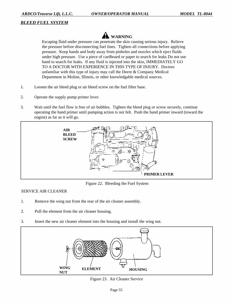
BLEED FUEL SYSTEM
WARNINGEscaping fluid under pressure can penetrate the skin causing serious injury. Relievethe pressure before disconnecting fuel lines. Tighten all connections before applyingpressure. Keep hands and body away from pinholes and nozzles which eject fluidsunder high pressure. Use a piece of cardboard or paper to search for leaks Do not usehand to search for leaks. If any fluid is injected into the skin, IMMEDIATELY GOTO A DOCTOR WITH EXPERIENCE IN THIS TYPE OF INJURY. Doctorsunfamiliar with this type of injury may call the Deere & Company MedicalDepartment in Moline, Illinois, or other knowledgable medical sources.
1. Loosen the air bleed plug or air bleed screw on the fuel filter base.
2. Operate the supply pump primer lever.
3. Wait until the fuel flow is free of air bubbles. Tighten the bleed plug or screw securely, continueoperating the hand primer until pumping action is not felt. Push the hand primer inward (toward theengine) as far as it will go.
Figure 22. Bleeding the Fuel System
AIRBLEEDSCREW
PRIMER LEVER
SERVICE AIR CLEANER
1. Remove the wing nut from the rear of the air cleaner assembly.
2. Pull the element from the air cleaner housing.
3. Insert the new air cleaner element into the housing and install the wing nut.
WINGNUT
HOUSINGELEMENT
Figure 23. Air Cleaner Service

Page 56
ARDCO/Traverse Lift, L.L.C. OWNER/OPERATOR MANUAL MODEL TL-8044
DRAIN AND REFILL COOLING SYSTEM
WARNINGNever attempt to remove the radiator cap from a hot engine. Escaping steamand hot coolant under pressure can cause serious burns.
1. Place a container beneath the radiator draincock.
WARNINGNever dispose of coolant by pouring it out on the ground or down a drain. TheEnvironmental Protection Agency (EPA) has established guidelines for coolantdisposal. Contact the local EPA office or the nearest engine distributor forinformation regarding proper disposal.
2. After making sure the engine is cool, remove the radiator cap.
3. Open the radiator draincock by turning it counterclockwise. Allow the coolant to drain into the container.
4. Position a container beneath the engine block draincock, open the draincock and allow the coolant todrain from the engine block into the container.
5. Discard the old coolant in a manner prescribed by the EPA or contact a local engine distributor fordisposal information.
6. Close the engine block draincock and the radiator draincock.
7. Refill the radiator with the recommended coolant/water mixture, start the engine and idle until enginereaches operating temperature and the thermostat opens. At this point, the coolant level in the radiatorwill drop. Fill the radiator with coolant and install the radiator cap.
ENGINE DRAIN COCK(BEHIND TURBOCHARGER
Figure 24. Draining and Refilling the Cooling System

Page 57
ARDCO/Traverse Lift, L.L.C. OWNER/OPERATOR MANUAL MODEL TL-8044
THERMOSTAT REMOVAL AND INSTALLATION
WARNINGNever attempt the following procedure on a hot engine. Steam and hot coolantescaping under pressure from the cooling system can cause serious burns.
1. Remove the thermostat as follows:
a. Drain the radiator.
b. Using a screwdriver, loosen the upper radiator hose clamp and pull the hose form the thermostathousing cover.
c. Using a 9/16” wrench, remove the two bolts from the thermostat housing and cover.
d. Separate the thermostat housing cover from the thermostat housing.
e. Remove the thermostat from the thermostat housing.
f. Discard the old thermostat gasket.
2. Install the thermostat as follows:
a. Position the thermostat into the thermostat housing, making sure that the thermostat seats fullyinto its recess.
b. Using gasket adhesive, position a new gasket on the thermostat housing cover.
c. Position the thermostat housing cover (with gasket) on the thermostat housing with the boltholesaligned.
d. Install the two bolts.
e. With the hose clamp positioned on the hose, slide the hose onto the thermostat housing cover.
f. Tighten the hose clamp.
g. Fill the radiator, start then engine and check for leaks.
Figure 25. Thermostat
HOUSINGCOVER
GASKET
THERMOSTAT
THERMOSTATHOUSING
UPPERRADIATORHOSE
HOSECLAMP

Page 58
ARDCO/Traverse Lift, L.L.C. OWNER/OPERATOR MANUAL MODEL TL-8044
THERMOSTAT TEST
1. Remove the thermostat, place it in a pot of water and position a thermometer to indicate watertemperature.
2. Heat the water on a burner while observing the thermometer.
3. The thermostat should open when the thermometer indicates a water temperature of 180 degrees F. Ifnot, replace the thermostat.
THERMOSTAT THERMOMETER
Figure 26. Thermostat Test
DRIVE BELT ADJUSTMENT
1. Hold a straightedge against the flat, outside of the drive belt. Make sure the straightedge is long enoughto reach from the crankshaft pulley to the alternator pulley.
2. Using a tension tester, apply twenty (20) pounds of pressure to a point halfway between the crankshaftpulley and the alternator pulley. If the belt deflects more than 3/4-inch away from the straightedge, thebelt must be adjusted as described in steps 3 and 4.
3. Loosen the upper and lower alternator bolts and apply outward pressure on the alternator front frame totighten the belt. Tighten the alternator bolts.
4. Recheck the belt tension and readjust if necessary until proper tension is reached.
ALTERNATORPULLEY
WATER PUMPPULLEY
CRANKSHAFTPULLEY
Figure 27. Drive Belt Tension Adjustment
Page 59
ARDCO/Traverse Lift, L.L.C. OWNER/OPERATOR MANUAL MODEL TL-8044
ELECTRICAL SYSTEM MAINTENANCE
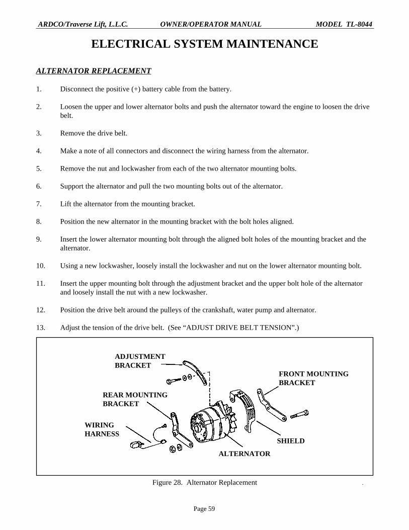
ALTERNATOR REPLACEMENT
1. Disconnect the positive (+) battery cable from the battery.
2. Loosen the upper and lower alternator bolts and push the alternator toward the engine to loosen the drivebelt.
3. Remove the drive belt.
4. Make a note of all connectors and disconnect the wiring harness from the alternator.
5. Remove the nut and lockwasher from each of the two alternator mounting bolts.
6. Support the alternator and pull the two mounting bolts out of the alternator.
7. Lift the alternator from the mounting bracket.
8. Position the new alternator in the mounting bracket with the bolt holes aligned.
9. Insert the lower alternator mounting bolt through the aligned bolt holes of the mounting bracket and thealternator.
10. Using a new lockwasher, loosely install the lockwasher and nut on the lower alternator mounting bolt.
11. Insert the upper mounting bolt through the adjustment bracket and the upper bolt hole of the alternatorand loosely install the nut with a new lockwasher.
12. Position the drive belt around the pulleys of the crankshaft, water pump and alternator.
13. Adjust the tension of the drive belt. (See “ADJUST DRIVE BELT TENSION”.)
ADJUSTMENTBRACKET
REAR MOUNTINGBRACKET
WIRINGHARNESS
ALTERNATOR
SHIELD
FRONT MOUNTINGBRACKET
Figure 28. Alternator Replacement

Page 60
ARDCO/Traverse Lift, L.L.C. OWNER/OPERATOR MANUAL MODEL TL-8044
BATTERY REPLACEMENT
WARNINGThe Environmental Protection Agency (EPA) has established guidelines for thedisposal of batteries. Make certain that EPA requirements are met whendisposing of batteries.
1. Remove the nut from each battery post.
2. Remove the battery ground cable from the negative (-) battery post, then remove the positive cable fromthe positive (+) battery post.
3. Loosen the two battery clamp nuts and lift the hold-down clamp from the battery.
4. Lift the battery from the forklift.
5. Position the new battery in the forklift.
6. Place the battery hold-down clamp on the battery with the threaded rods of the clamp hooked into theslots provided.
7. Tighten the hold-down clamp nuts.
8. Position the battery cables on the posts in the following order: first the red cable to the positive (+) post,and then the black cable to the negative (-) post.
9. Install a nut on each battery post.
10. Dispose of the old battery in a manner approved by the EPA.
HOLD DOWNCLAMP
BATTERY
BATTERYCABLE
THREADEDROD
Figure 29. Battery Replacement

Page 61
ARDCO/Traverse Lift, L.L.C. OWNER/OPERATOR MANUAL MODEL TL-8044
FUSE REPLACEMENT
1. Using a screwdriver, remove the four crosshead screws form the hourmeter panel.
2. Pull the hourmeter panel out as far as the attached wiring will allow. The fuse block is located inside theoperator’s panel, on the right wall.
3. Using a fuse puller, remove the faulty fuse and replace.
4. Position the hourmeter panel back on the operator’s panel and install the four screws.
FRONT AXLE LOCK(10 AMP)
BUZZER: EMERGENCY BRAKE &LOW BRAKE PRESSURE (10 AMP)
INSTRUMENT PANEL& HORN (15 AMP)
FUEL INJECTIONPUMP (10 AMP)
BACKUP ALARM &HOURMETER (15 AMP)
JOYSTICKS(10 AMPS)
HOURMETERPANEL
TRANSMISSION MAINTENANCE
TRANSMISSION OIL CHANGE
NOTETransmission oil should be changed with the transmission warm.
1. Position a container beneath the oil drain plug located on the lower front of the transmission.
WARNINGNever dispose of transmission oil by pouring it out on the ground or pouring itdown a drain. Contact the local Environmental Protection Agency (EPA) officeor the nearest John Deere distributor for proper disposal information.
2. Remove the plug and allow the oil to drain into the container. Install the drain plug.
3. If this is the first transmission service, fill the transmission with 4 gallons of C-3 type transmission oil. Ifthis is not the first time the transmission has been serviced, disregard this step and proceed to step 4.

Page 62
ARDCO/Traverse Lift, L.L.C. OWNER/OPERATOR MANUAL MODEL TL-8044
4. Start the engine, put the transmission in neutral and check the oil level on the transmission dipstick.
5. Fill the transmission to the proper level shown on the dipstick.
6. Dispose of transmission oil in a manner prescribed by the EPA.
BREATHER
TRANSMISSIONMAGNETIC OILDRAIN PLUG
Figure 31. Transmission Drain Plug Location
TRANSMISSION FILTER ELEMENT REPLACEMENT
1. With the engine shut off, place a container beneath the transmission filter, located at the right front of theengine compartment.
2. Using a filter wrench, remove the filter element.
3. Apply a light coat of transmission fluid to the surface of the element’s gasket.
4. Install the element onto the filter base and hand tighten only.
5. Start the engine and check for leaks. Tighten the element if leaking.
BASE
ELEMENT
Figure 32. Transmission Filter

Page 63
ARDCO/Traverse Lift, L.L.C. OWNER/OPERATOR MANUAL MODEL TL-8044
AXLE MAINTENANCE
AXLE LUBRICANT CHANGE
WARNINGNever dispose of axle lubricant by pouring it out on the ground or down a drain.The Environmental Protection Agency has established guidelines for lubricantdisposal. Contact the local EPA office or the nearest John Deere distributor forthe proper disposal procedure.
1. Position a container beneath the differential drain plug, located on the underside, center of the axle.
2. Remove the drain plug and allow lubricant to drain into the container.
FILL PLUGDRAIN PLUG
Figure 34. Axle Drain and Fill Plug Location
3. After the axle has drained, install the drain plug and remove the fill plug, located in the center of the axlehousing.
4. Fill the axle through the fill opening until the lubricant level is even with the bottom of the opening.Install the fill plug.
5. To drain a planetary, park the forklift so that the fill plug on the planetary is in the lowest position.Remove the plug and allow the planetary to drain. After draining, park the forklift so that the arrow,located on the face of the planetary hub, is pointed downward. Fill the planetary to a level even with thebottom of the drain plug opening. Install the drain plug. Repeat this step for each planetary.
ARROW
FILL / DRAIN PLUG
Figure 34. Planetary Check and Fill Plug

Page 64
ARDCO/Traverse Lift, L.L.C. OWNER/OPERATOR MANUAL MODEL TL-8044
HYDRAULIC SYSTEM MAINTENANCE
HYDRAULIC STRAINER ELEMENT REPLACEMENT
1. Separate the piping from the top of the strainer.
2. Remove the four bolts form the base of the strainer.
3. Lift the strainer assembly from the hydraulic reservoir.
4. Remove the cover to expose the element.
5. Using a 17 mm wrench, remove the element restraining nut, plate and spring.
6. Remove the element.
7. Position the new element on the center post of the strainer assembly.
8. Install the spring, plate and nut.
9. Check the condition of the rubber seal and replace it if damaged.
10. Position the rubber seal back into the groove of the strainer base.
11. Position the element cover back on the strainer base with the rubber seal properly positioned.
12. Clean all remnants of the old base gasket from the base of the strainer and the reservoir.
13. Install a new gasket, using the gasket sealer.
14. Position the strainer assembly on the reservoir with the four bolt holes aligned.
15. Install the four bolts and reconnect the piping.
BASE
SEAL
ELEMENT
COVER
SPRING
PLATE
NUT
Figure 35. Hydraulic Strainer Element Replacement
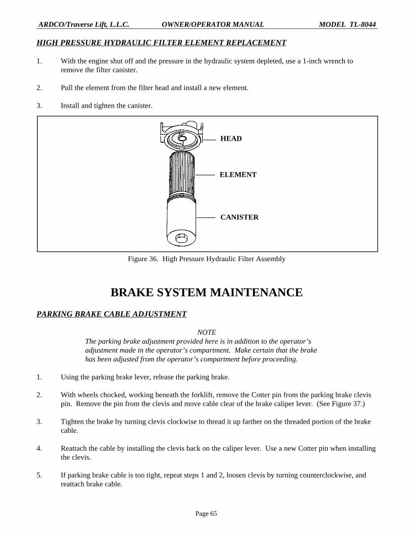
Page 65
ARDCO/Traverse Lift, L.L.C. OWNER/OPERATOR MANUAL MODEL TL-8044
HIGH PRESSURE HYDRAULIC FILTER ELEMENT REPLACEMENT
1. With the engine shut off and the pressure in the hydraulic system depleted, use a 1-inch wrench toremove the filter canister.
2. Pull the element from the filter head and install a new element.
3. Install and tighten the canister.
HEAD
ELEMENT
CANISTER
Figure 36. High Pressure Hydraulic Filter Assembly
BRAKE SYSTEM MAINTENANCE
PARKING BRAKE CABLE ADJUSTMENT
NOTEThe parking brake adjustment provided here is in addition to the operator’sadjustment made in the operator’s compartment. Make certain that the brakehas been adjusted from the operator’s compartment before proceeding.
1. Using the parking brake lever, release the parking brake.
2. With wheels chocked, working beneath the forklift, remove the Cotter pin from the parking brake clevispin. Remove the pin from the clevis and move cable clear of the brake caliper lever. (See Figure 37.)
3. Tighten the brake by turning clevis clockwise to thread it up farther on the threaded portion of the brakecable.
4. Reattach the cable by installing the clevis back on the caliper lever. Use a new Cotter pin when installingthe clevis.
5. If parking brake cable is too tight, repeat steps 1 and 2, loosen clevis by turning counterclockwise, andreattach brake cable.
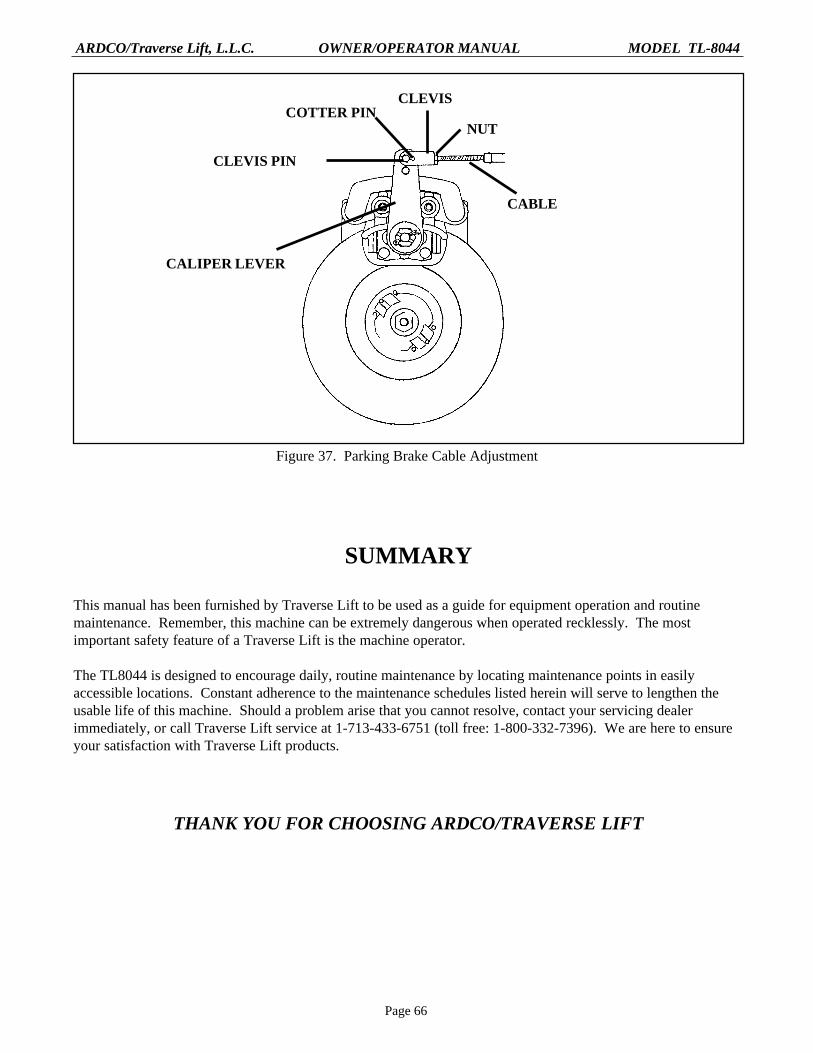
Page 66
ARDCO/Traverse Lift, L.L.C. OWNER/OPERATOR MANUAL MODEL TL-8044
CLEVIS PIN
CALIPER LEVER
CABLE
NUT
CLEVISCOTTER PIN
Figure 37. Parking Brake Cable Adjustment
SUMMARY
This manual has been furnished by Traverse Lift to be used as a guide for equipment operation and routinemaintenance. Remember, this machine can be extremely dangerous when operated recklessly. The mostimportant safety feature of a Traverse Lift is the machine operator.
The TL8044 is designed to encourage daily, routine maintenance by locating maintenance points in easilyaccessible locations. Constant adherence to the maintenance schedules listed herein will serve to lengthen theusable life of this machine. Should a problem arise that you cannot resolve, contact your servicing dealerimmediately, or call Traverse Lift service at 1-713-433-6751 (toll free: 1-800-332-7396). We are here to ensureyour satisfaction with Traverse Lift products.
THANK YOU FOR CHOOSING ARDCO/TRAVERSE LIFT