aqualink rs - inyopools.comimages.inyopools.com/cloud/documents/jandy-controls-pda... · aqualink®...
TRANSCRIPT

Installation Data
Installation Man u al
AquaLink® RSPDA - Pool Digital Assistant
WARNINGFOR YOUR SAFETY - This product must be installed and serviced by a pro fes sion al pool/spa service technician. The procedures in this manual must be followed ex act ly. Failure to follow warning notices and instructions may result in property damage, serious injury, or death.
Pool/Spa Combination Systems and Pool Only/Spa Only Systems(Models PS4, PS6, PS8, P4, and P8)
H05
7220
0A
ATTENTIONThis device complies with part 15 of the FCC Rules. Operation is subject to the following two conditions: (1) This device may not cause harmful interference, and (2) this device must accept any interference received, including interference that may cause undesired operation.
NOTE: This equipment has been tested and found to comply with the limits for a Class B digital device, pursuant to part 15 of the FCC Rules. These limits are designed to provide reasonable protection against harmful interference in a residential installation. This equipment generates, uses and can radiate radio frequency energy and, if not installed and used in accordance with the instructions, may cause harmful interference to radio communications. However, there is no guarantee that interference will not occur in a particular installation. If this equipment does cause harmful interference to radio or television reception, which can be determined by turning the equipment off and on, the user is encouraged to try to correct the interference by one or more of the following measures:
• Reorient or relocate the receiving antenna.• Increase the separation between the equipment and receiver.• Connect the equipment to an electrical source on a circuit different from that to which the receiver is connected.• Consult the dealer or an experienced radio/TV technician for help
Modifi cations made to this equipment, which are not authorized by the manufacturer, may void the user’s authority to operate this equipment.

Page 3
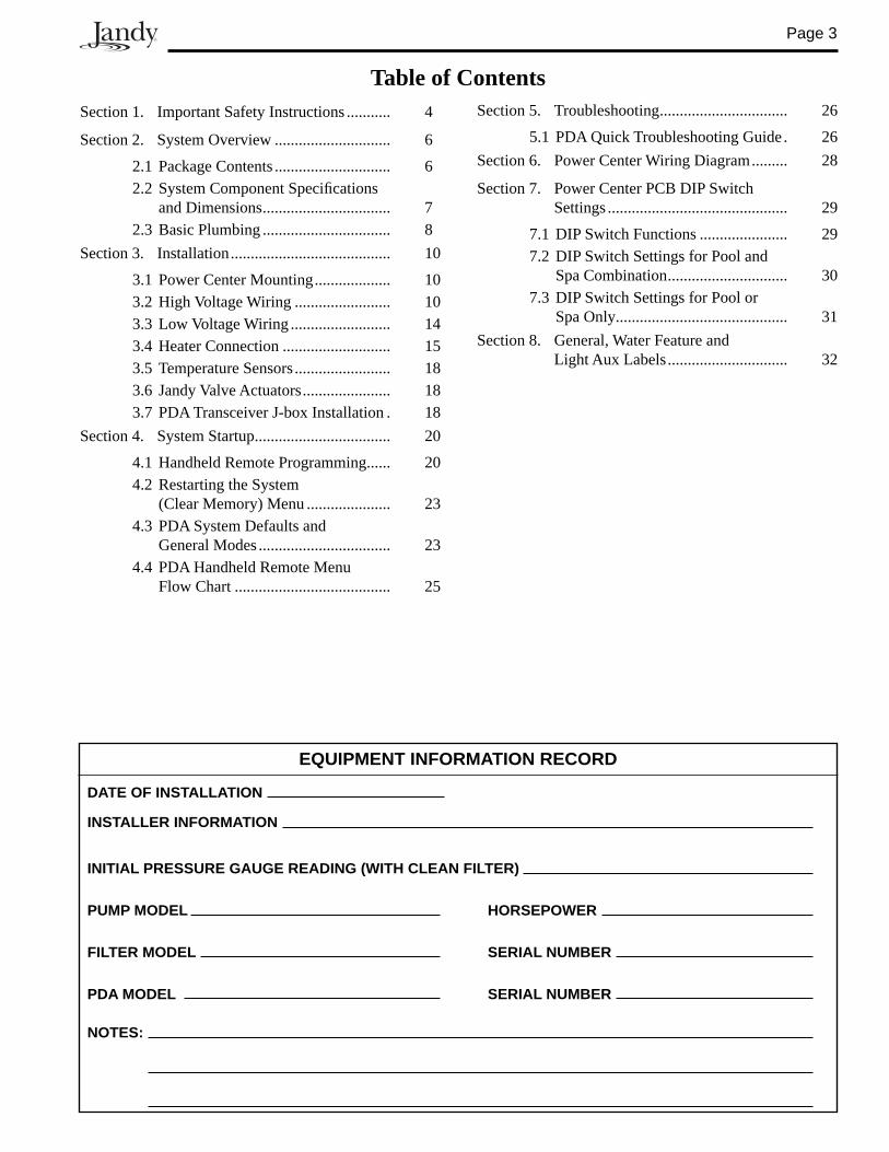
Table of ContentsSection 1. Important Safety Instructions ........... 4
Section 2. System Overview ............................. 6
2.1 Package Contents ............................. 62.2 System Component Specifi cations
and Dimensions ................................ 72.3 Basic Plumbing ................................ 8
Section 3. Installation ........................................ 10
3.1 Power Center Mounting ................... 103.2 High Voltage Wiring ........................ 103.3 Low Voltage Wiring ......................... 143.4 Heater Connection ........................... 153.5 Temperature Sensors ........................ 183.6 Jandy Valve Actuators ...................... 183.7 PDA Transceiver J-box Installation . 18
Section 4. System Startup .................................. 20
4.1 Handheld Remote Programming ...... 204.2 Restarting the System
(Clear Memory) Menu ..................... 234.3 PDA System Defaults and
General Modes ................................. 234.4 PDA Handheld Remote Menu
Flow Chart ....................................... 25
Section 5. Troubleshooting ................................ 26
5.1 PDA Quick Troubleshooting Guide . 26Section 6. Power Center Wiring Diagram ......... 28
Section 7. Power Center PCB DIP Switch Settings ............................................. 29
7.1 DIP Switch Functions ...................... 297.2 DIP Switch Settings for Pool and
Spa Combination .............................. 307.3 DIP Switch Settings for Pool or
Spa Only........................................... 31Section 8. General, Water Feature and
Light Aux Labels .............................. 32
DATE OF INSTALLATION
INSTALLER INFORMATION
INITIAL PRESSURE GAUGE READING (WITH CLEAN FILTER)
PUMP MODEL HORSEPOWER
FILTER MODEL SERIAL NUMBER
PDA MODEL SERIAL NUMBER
NOTES:
EQUIPMENT INFORMATION RECORD
Page 4
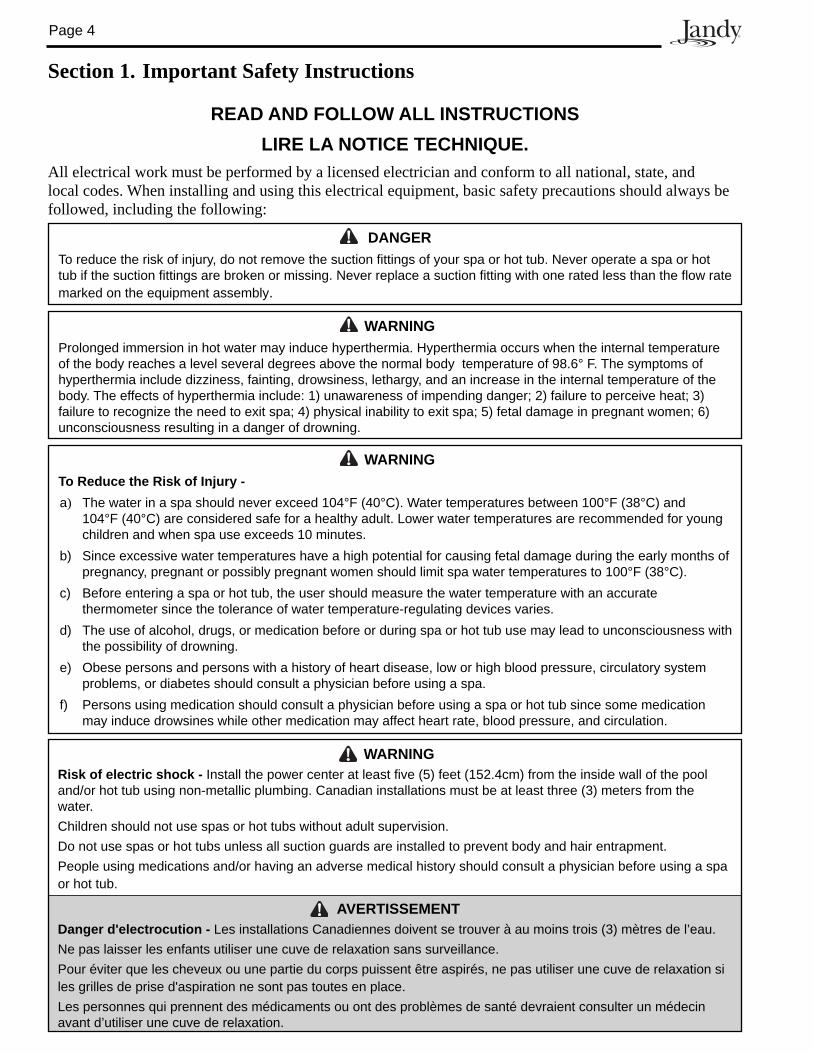
Section 1. Important Safety Instructions
READ AND FOLLOW ALL INSTRUCTIONSLIRE LA NOTICE TECHNIQUE.
All electrical work must be performed by a licensed electrician and conform to all national, state, and local codes. When installing and using this electrical equipment, basic safety precautions should always be followed, including the following:
WARNINGProlonged immersion in hot water may induce hyperthermia. Hyperthermia occurs when the internal temperature of the body reaches a level several degrees above the normal body temperature of 98.6° F. The symptoms of hyperthermia include dizziness, fainting, drowsiness, lethargy, and an increase in the internal temperature of the body. The effects of hyperthermia include: 1) unawareness of impending danger; 2) failure to perceive heat; 3) failure to recognize the need to exit spa; 4) physical inability to exit spa; 5) fetal damage in pregnant women; 6) unconsciousness resulting in a danger of drowning.
DANGERTo reduce the risk of injury, do not remove the suction fittings of your spa or hot tub. Never operate a spa or hot tub if the suction fittings are broken or missing. Never replace a suction fitting with one rated less than the flow rate marked on the equipment assembly.
WARNINGTo Reduce the Risk of Injury -a) The water in a spa should never exceed 104°F (40°C). Water temperatures between 100°F (38°C) and
104°F (40°C) are considered safe for a healthy adult. Lower water temperatures are recommended for young children and when spa use exceeds 10 minutes.
b) Since excessive water temperatures have a high potential for causing fetal damage during the early months of pregnancy, pregnant or possibly pregnant women should limit spa water temperatures to 100°F (38°C).
c) Before entering a spa or hot tub, the user should measure the water temperature with an accurate thermometer since the tolerance of water temperature-regulating devices varies.
d) The use of alcohol, drugs, or medication before or during spa or hot tub use may lead to unconsciousness with the possibility of drowning.
e) Obese persons and persons with a history of heart disease, low or high blood pressure, circulatory system problems, or diabetes should consult a physician before using a spa.
f) Persons using medication should consult a physician before using a spa or hot tub since some medication may induce drowsines while other medication may affect heart rate, blood pressure, and circulation.
WARNINGRisk of electric shock - Install the power center at least five (5) feet (152.4cm) from the inside wall of the pool and/or hot tub using non-metallic plumbing. Canadian installations must be at least three (3) meters from the water. Children should not use spas or hot tubs without adult supervision.Do not use spas or hot tubs unless all suction guards are installed to prevent body and hair entrapment.People using medications and/or having an adverse medical history should consult a physician before using a spa or hot tub.
AVERTISSEMENTDanger d'electrocution - Les installations Canadiennes doivent se trouver à au moins trois (3) mètres de l’eau.Ne pas laisser les enfants utiliser une cuve de relaxation sans surveillance.Pour éviter que les cheveux ou une partie du corps puissent être aspirés, ne pas utiliser une cuve de relaxation si les grilles de prise d'aspiration ne sont pas toutes en place.Les personnes qui prennent des médicaments ou ont des problèmes de santé devraient consulter un médecin avant d’utiliser une cuve de relaxation.
Page 5
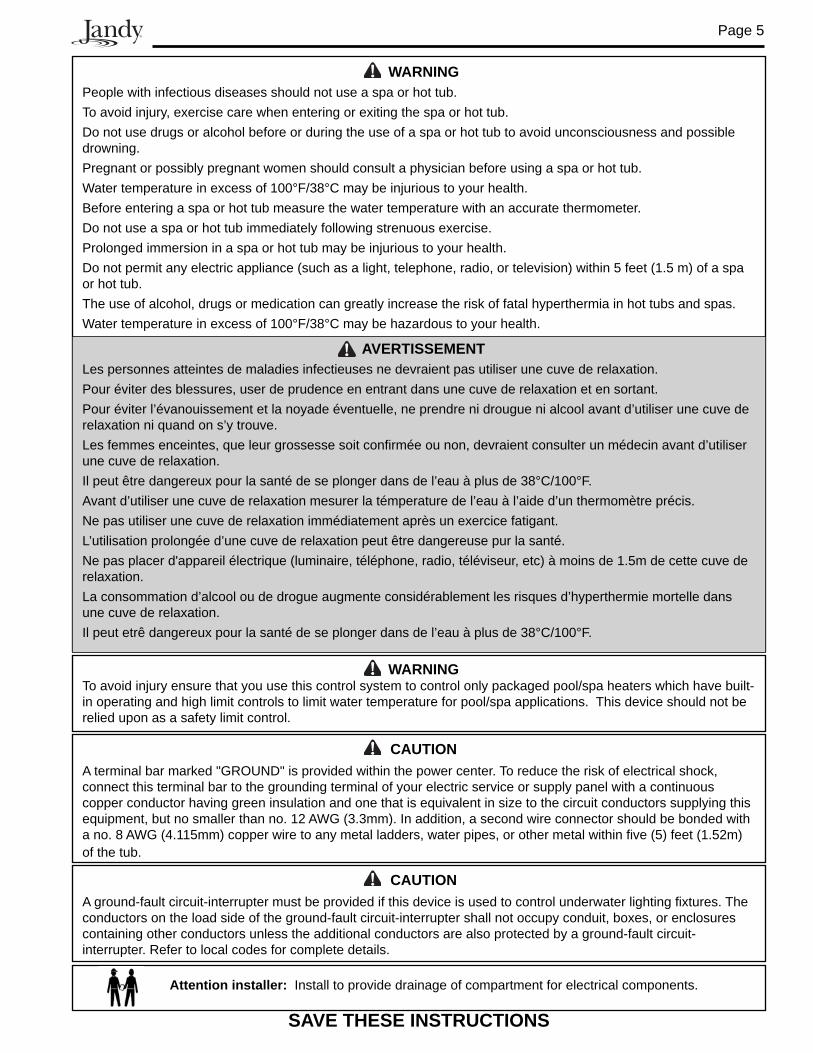
CAUTIONA ground-fault circuit-interrupter must be provided if this device is used to control underwater lighting fixtures. The conductors on the load side of the ground-fault circuit-interrupter shall not occupy conduit, boxes, or enclosures containing other conductors unless the additional conductors are also protected by a ground-fault circuit-interrupter. Refer to local codes for complete details.
CAUTIONA terminal bar marked "GROUND" is provided within the power center. To reduce the risk of electrical shock, connect this terminal bar to the grounding terminal of your electric service or supply panel with a continuous copper conductor having green insulation and one that is equivalent in size to the circuit conductors supplying this equipment, but no smaller than no. 12 AWG (3.3mm). In addition, a second wire connector should be bonded with a no. 8 AWG (4.115mm) copper wire to any metal ladders, water pipes, or other metal within five (5) feet (1.52m) of the tub.
SAVE THESE INSTRUCTIONS
WARNINGPeople with infectious diseases should not use a spa or hot tub.To avoid injury, exercise care when entering or exiting the spa or hot tub.Do not use drugs or alcohol before or during the use of a spa or hot tub to avoid unconsciousness and possible drowning.Pregnant or possibly pregnant women should consult a physician before using a spa or hot tub. Water temperature in excess of 100°F/38°C may be injurious to your health. Before entering a spa or hot tub measure the water temperature with an accurate thermometer. Do not use a spa or hot tub immediately following strenuous exercise.Prolonged immersion in a spa or hot tub may be injurious to your health.Do not permit any electric appliance (such as a light, telephone, radio, or television) within 5 feet (1.5 m) of a spa or hot tub.The use of alcohol, drugs or medication can greatly increase the risk of fatal hyperthermia in hot tubs and spas.Water temperature in excess of 100°F/38°C may be hazardous to your health.
AVERTISSEMENTLes personnes atteintes de maladies infectieuses ne devraient pas utiliser une cuve de relaxation.Pour éviter des blessures, user de prudence en entrant dans une cuve de relaxation et en sortant.Pour éviter l’évanouissement et la noyade éventuelle, ne prendre ni drougue ni alcool avant d’utiliser une cuve de relaxation ni quand on s’y trouve.Les femmes enceintes, que leur grossesse soit confi rmée ou non, devraient consulter un médecin avant d’utiliser une cuve de relaxation.Il peut être dangereux pour la santé de se plonger dans de l’eau à plus de 38°C/100°F.Avant d’utiliser une cuve de relaxation mesurer la témperature de l’eau à l’aide d’un thermomètre précis.Ne pas utiliser une cuve de relaxation immédiatement après un exercice fatigant.L’utilisation prolongée d’une cuve de relaxation peut être dangereuse pur la santé.Ne pas placer d'appareil électrique (luminaire, téléphone, radio, téléviseur, etc) à moins de 1.5m de cette cuve de relaxation.La consommation d’alcool ou de drogue augmente considérablement les risques d’hyperthermie mortelle dans une cuve de relaxation.Il peut etrê dangereux pour la santé de se plonger dans de l’eau à plus de 38°C/100°F.
Attention installer: Install to provide drainage of compartment for electrical components.
WARNINGTo avoid injury ensure that you use this control system to control only packaged pool/spa heaters which have built-in operating and high limit controls to limit water temperature for pool/spa applications. This device should not be relied upon as a safety limit control.
Page 6
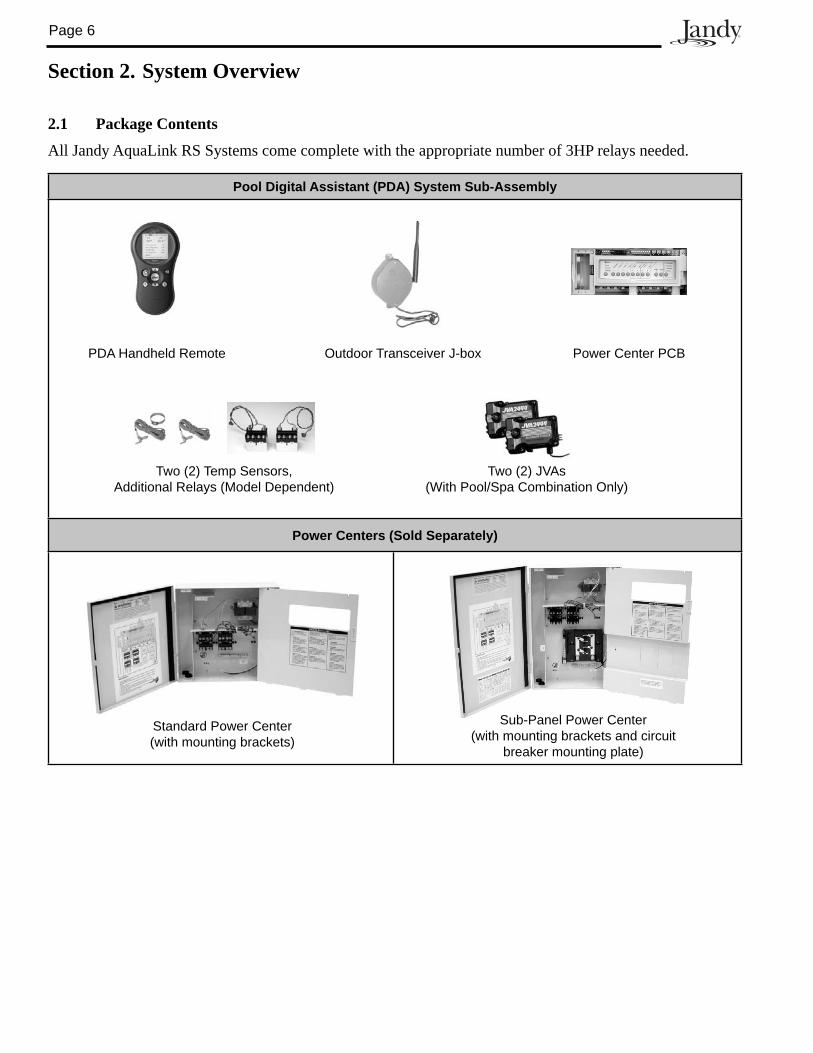
Section 2. System Overview
2.1 Package Contents
All Jandy AquaLink RS Systems come complete with the appropriate number of 3HP relays needed.
Pool Digital Assistant (PDA) System Sub-Assembly
Power Centers (Sold Separately)
Standard Power Center(with mounting brackets)
Sub-Panel Power Center(with mounting brackets and circuit
breaker mounting plate)
Two (2) JVAs (With Pool/Spa Combination Only)
PDA Handheld Remote Outdoor Transceiver J-box Power Center PCB
Two (2) Temp Sensors, Additional Relays (Model Dependent)
Page 7
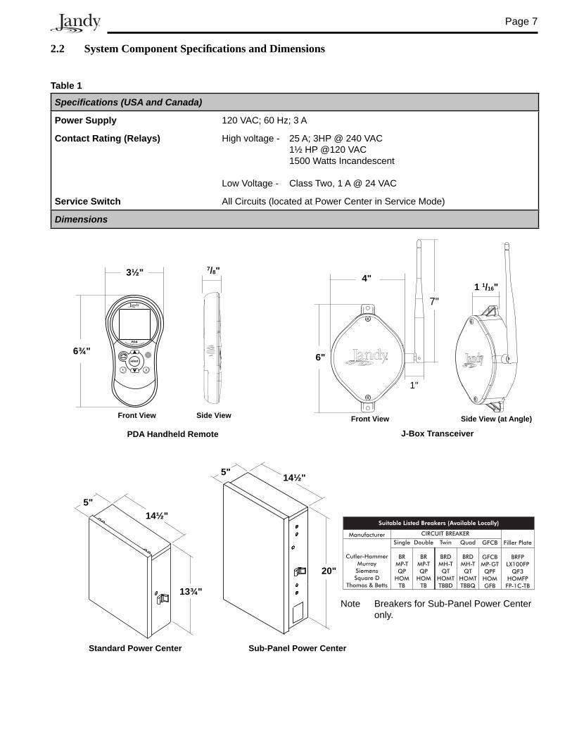
2.2 System Component Specifi cations and Dimensions
Table 1
Specifications (USA and Canada)
Power Supply 120 VAC; 60 Hz; 3 A
Contact Rating (Relays) High voltage - 25 A; 3HP @ 240 VAC 1½ HP @120 VAC 1500 Watts Incandescent
Low Voltage - Class Two, 1 A @ 24 VAC
Service Switch All Circuits (located at Power Center in Service Mode)
Dimensions
Standard Power Cen ter
5"14½"
13¾"
Sub-Panel Power Cen ter
20"
14½"5"
Note Breakers for Sub-Panel Power Center only.
PDA Handheld Remote
Front View
3½"
6¾"Pool Digital Assistant
1 2
selectback
PDA
7/8"
Side View
J-Box Transceiver
1 1/16"
Side View (at Angle)
4"
6"
1"
7"
Front View
Page 8
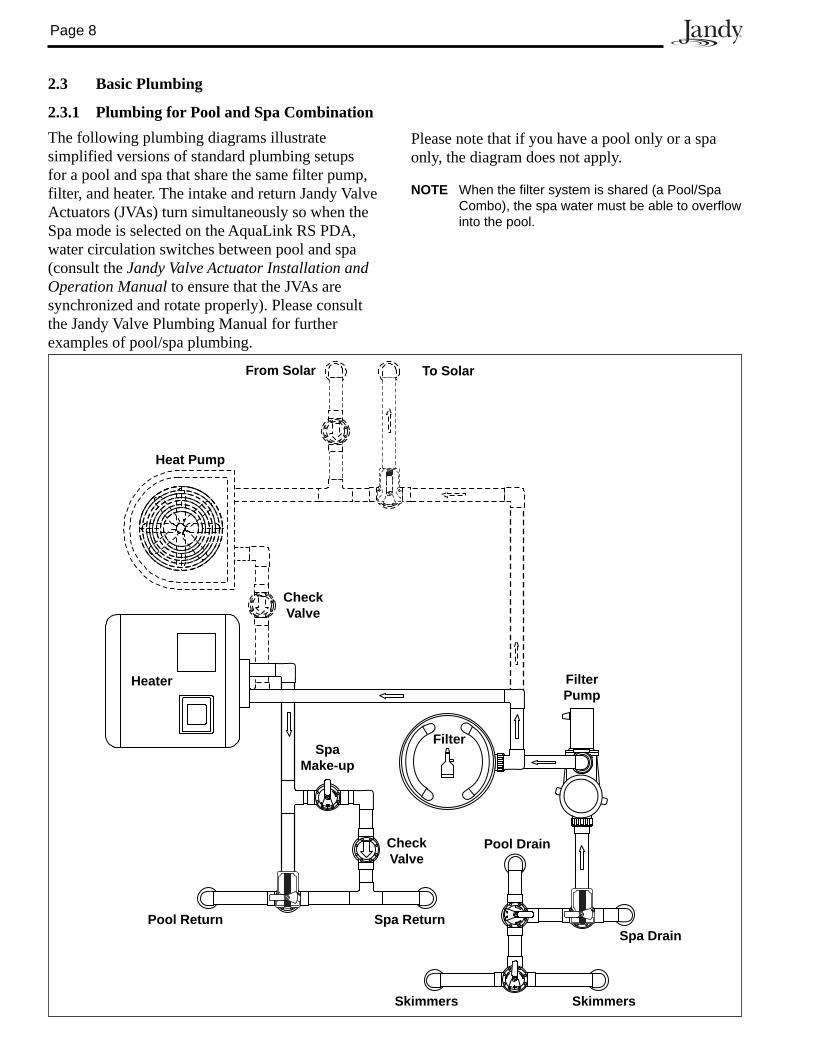
2.3 Basic Plumbing
2.3.1 Plumbing for Pool and Spa CombinationThe following plumbing diagrams illustrate simplified versions of standard plumbing setups for a pool and spa that share the same filter pump, filter, and heater. The intake and return Jandy Valve Actuators (JVAs) turn si mul ta neous ly so when the Spa mode is selected on the AquaLink RS PDA, water circulation switches between pool and spa (consult the Jandy Valve Actuator Installation and Operation Manual to ensure that the JVAs are synchronized and rotate properly). Please consult the Jandy Valve Plumb ing Manual for further examples of pool/spa plumbing.
Heater
Filter
FilterPump
Pool Drain
Spa DrainSpa ReturnPool Return
CheckValve
SpaMake-up
CheckValve
Heat Pump
SkimmersSkimmers
From Solar To Solar
Please note that if you have a pool only or a spa only, the diagram does not apply.
NOTE When the filter system is shared (a Pool/Spa Combo), the spa water must be able to overflow into the pool.
Page 9
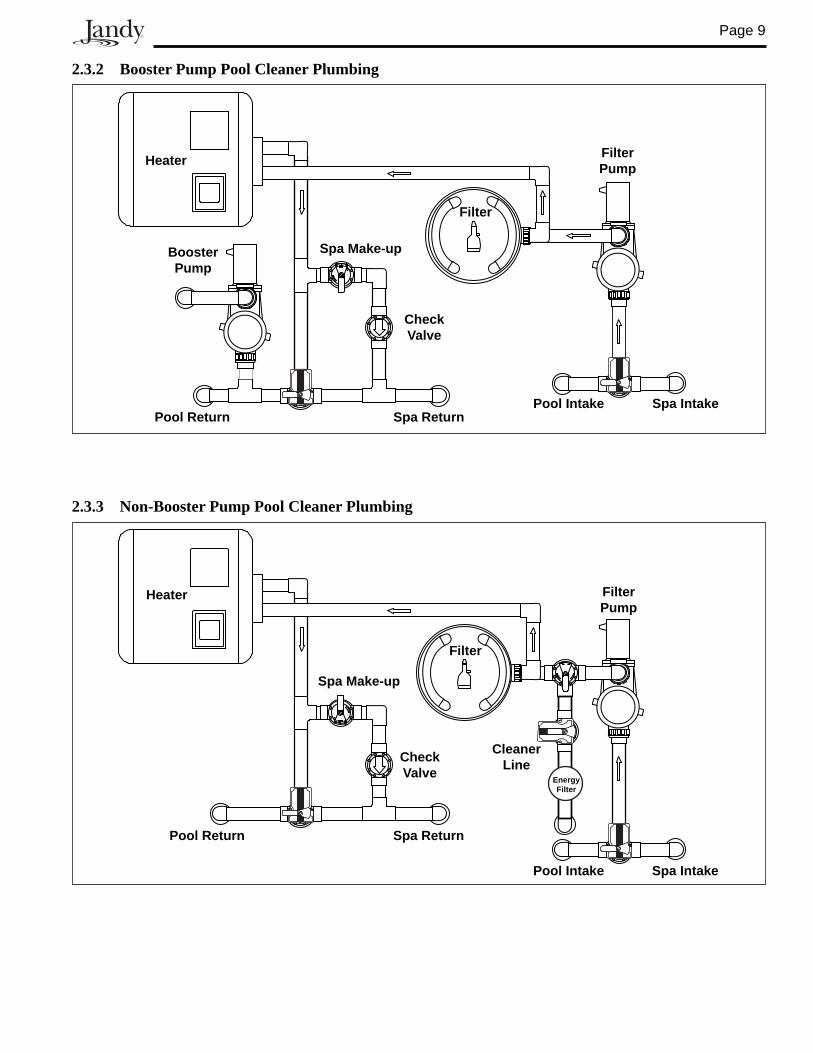
2.3.2 Booster Pump Pool Cleaner Plumbing
Heater
Filter
FilterPump
Pool Intake Spa IntakeSpa ReturnPool Return
CheckValve
Spa Make-upBoosterPump
2.3.3 Non-Booster Pump Pool Cleaner Plumbing
Filter
FilterPump
Pool Intake Spa Intake
Spa ReturnPool Return
CheckValve
Spa Make-up
EnergyFilter
CleanerLine
Heater
Page 10
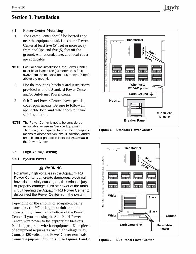
3.1 Power Center Mounting1. The Power Center should be located at or
near the equipment pad. Locate the Power Center at least fi ve (5) feet or more away from pool/spa and fi ve (5) feet off the ground. All na tion al, state, and local codes are applicable.
NOTE For Canadian installations, the Power Center must be at least three (3) meters (9.8 feet) away from the pool/spa and 1.5 meters (5 feet) above the ground.
2. Use the mounting brackets and instructions provided with the Standard Power Center and/or Sub-Panel Power Center.
3. Sub-Panel Power Centers have special code requirements. Be sure to follow all applicable local and state codes to insure safe installation.
NOTE The Power Center is not to be considered as suitable for use as Service Equipment. Therefore, it is required to have the appropriate means of disconnection, circuit isolation, and/or branch circuit protection installed upstream of the Power Center.
3.2 High Voltage Wiring
3.2.1 System Power
Figure 2. Sub-Panel Power Center
Filter Pump Relay Aux. 3 Relay
Transformer
Earth Ground
Black White
Prim
ary
Low
vol
tage
race
way
, do
not r
un h
igh
volta
ge in
this
com
part
men
t
From Main Power
Ground
White
WhiteBlack
Black
Filter Pump Relay Aux. 3 Relay
Ground
Neutral
Transformer
Earth Ground
Breaker Panel
To 120 VAC Breaker
Neutral
Black White
Wire nut to120 VAC power
Low
vol
tage
race
way
, do
not r
un h
igh
volta
ge in
this
com
part
men
t
Prim
ary
Figure 1. Standard Power Center
Section 3. Installation
WARNINGPotentially high voltages in the AquaLink RS Power Center can create dangerous electrical hazards, possibly causing death, serious injury or property damage. Turn off power at the main circuit feeding the AquaLink RS Power Center to disconnect the Power Center from the system.
Depending on the amount of equipment being controlled, run ½" or larger conduit from the power supply panel to the bottom of the Power Center. If you are using the Sub-Panel Power Center, wire power to the appropriate breakers. Pull in ap pro pri ate wire for equipment. Each piece of equipment requires its own high voltage relay. Connect 120 volts to the Power Center terminals. Connect equipment ground(s). See Figures 1 and 2.
Page 11
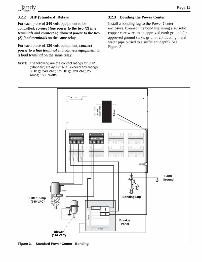
3.2.3 Bonding the Power CenterInstall a bonding lug to the Power Center enclosure. Connect the bond lug, using a #8 solid copper core wire, to an approved earth ground (an approved ground stake, grid, or conducting metal water pipe buried to a sufficient depth). See Figure 3.
3.2.2 3HP (Standard) RelaysFor each piece of 240 volt equipment to be controlled, connect line power to the two (2) line terminals and connect equipment power to the two (2) load terminals on the same relay.
For each piece of 120 volt equipment, connect power to a line terminal and connect equipment to a load terminal on the same relay.
NOTE The following are the contact ratings for 3HP (Standard) Relay. DO NOT exceed any ratings. 3 HP @ 240 VAC; 1½ HP @ 120 VAC; 25 Amps; 1500 Watts.
Figure 3. Standard Power Center - Bonding
Filter Pump Relay Aux. 3 Relay
Load2
Line2
Load1
Line1
Ground
Neutral
Bonding Lug
Earth Ground
Breaker Panel
Blower (120 VAC)
Filter Pump (240 VAC)
Prim
ary
24 V
AC
Tr
ansf
orm
er
Page 12
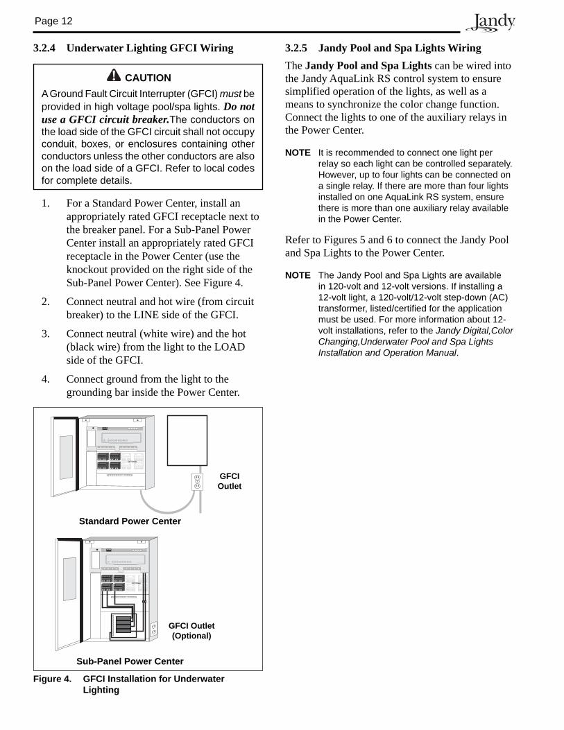
3.2.4 Underwater Lighting GFCI Wiring
Figure 4. GFCI Installation for Underwater Lighting
GFCI Outlet
OPTIONAL
Standard Power Center
GFCI Outlet(Optional)
OPTIONAL
Sub-Panel Power Center
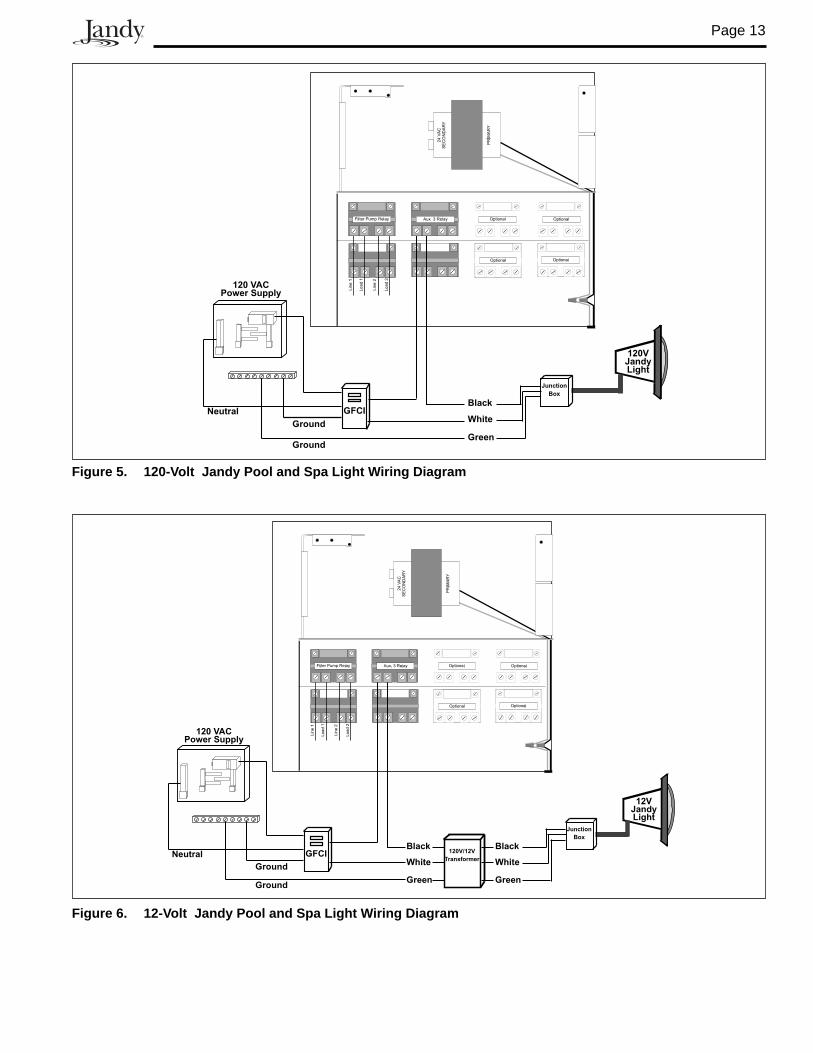
3.2.5 Jandy Pool and Spa Lights WiringThe Jandy Pool and Spa Lights can be wired into the Jandy AquaLink RS control system to ensure simplified operation of the lights, as well as a means to synchronize the color change function. Connect the lights to one of the auxiliary relays in the Power Center.
NOTE It is recommended to connect one light per relay so each light can be controlled separately. However, up to four lights can be connected on a single relay. If there are more than four lights installed on one AquaLink RS system, ensure there is more than one auxiliary relay available in the Power Center.
Refer to Figures 5 and 6 to connect the Jandy Pool and Spa Lights to the Power Center.
NOTE The Jandy Pool and Spa Lights are available in 120-volt and 12-volt versions. If installing a 12-volt light, a 120-volt/12-volt step-down (AC) transformer, listed/certified for the application must be used. For more information about 12-volt installations, refer to the Jandy Digital,Color Changing,Underwater Pool and Spa Lights Installation and Operation Manual.
CAUTIONA Ground Fault Circuit Interrupter (GFCI) must be provided in high voltage pool/spa lights. Do not use a GFCI circuit breaker.The conductors on the load side of the GFCI circuit shall not occupy conduit, boxes, or enclosures containing other conductors unless the other conductors are also on the load side of a GFCI. Refer to local codes for complete details.
1. For a Standard Power Center, install an appropriately rated GFCI receptacle next to the breaker panel. For a Sub-Panel Power Center install an appropriately rated GFCI receptacle in the Power Center (use the knockout provided on the right side of the Sub-Panel Power Center). See Figure 4.
2. Connect neutral and hot wire (from circuit breaker) to the LINE side of the GFCI.
3. Connect neutral (white wire) and the hot (black wire) from the light to the LOAD side of the GFCI.
4. Connect ground from the light to the grounding bar inside the Power Center.
Page 13
GFCIBlack
White
Green
120VJandyLight
Ground
Ground
Neutral
120 VACPower Supply
Junction
Box
Figure 5. 120-Volt Jandy Pool and Spa Light Wiring Diagram
Figure 6. 12-Volt Jandy Pool and Spa Light Wiring Diagram
GFCI
Ground
Ground
NeutralBlack
White
Green
12VJandyLight
Black
White
Green
120V/12V
Transformer
120 VACPower Supply
Junction
Box
Page 14
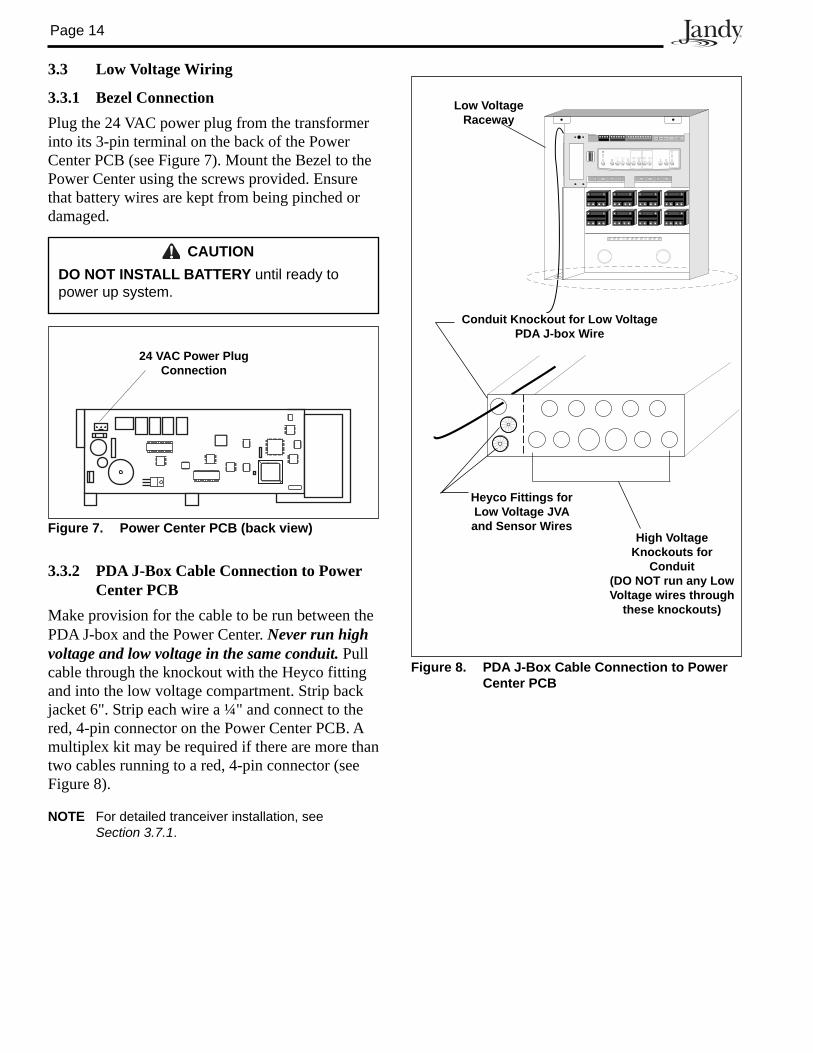
Figure 8. PDA J-Box Cable Connection to Power Center PCB
Conduit Knockout for Low Voltage PDA J-box Wire
Heyco Fittings for Low Voltage JVA and Sensor Wires
Low Voltage Raceway
High Voltage Knock outs for
Conduit (DO NOT run any Low Voltage wires through
these knockouts)
3.3 Low Voltage Wiring
3.3.1 Bezel ConnectionPlug the 24 VAC power plug from the transformer into its 3-pin terminal on the back of the Power Center PCB (see Figure 7). Mount the Bezel to the Power Center using the screws provided. Ensure that battery wires are kept from being pinched or damaged.
CAUTIONDO NOT INSTALL BATTERY until ready to power up system.
3.3.2 PDA J-Box Cable Connection to Power Center PCB
Make provision for the cable to be run between the PDA J-box and the Power Center. Never run high voltage and low voltage in the same con duit. Pull cable through the knockout with the Heyco fitting and into the low voltage compartment. Strip back jacket 6". Strip each wire a ¼" and connect to the red, 4-pin connector on the Power Center PCB. A mul ti plex kit may be required if there are more than two cables running to a red, 4-pin connector (see Figure 8).
NOTE For detailed tranceiver installation, see Section 3.7.1.
Figure 7. Power Center PCB (back view)
24 VAC Power Plug Connection
Page 15
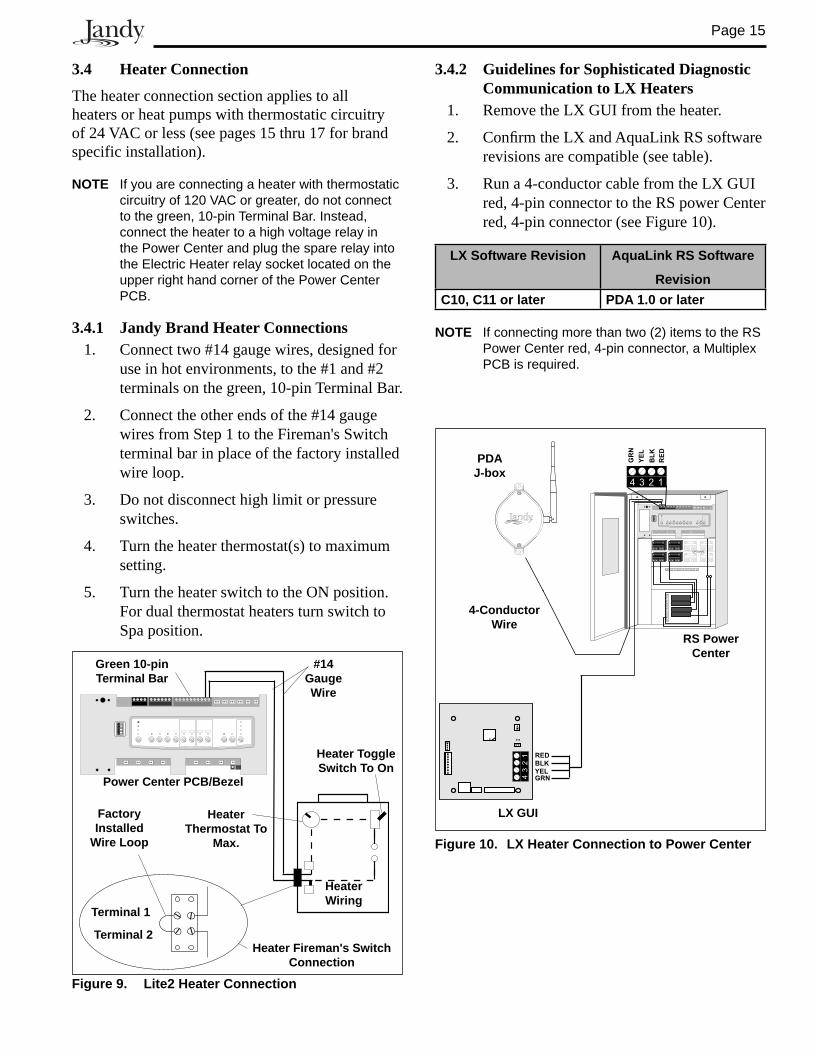
3.4 Heater Connection
The heater connection section applies to all heaters or heat pumps with thermostatic circuitry of 24 VAC or less (see pages 15 thru 17 for brand specific installation).
NOTE If you are connecting a heater with thermostatic circuitry of 120 VAC or greater, do not connect to the green, 10-pin Terminal Bar. Instead, connect the heater to a high voltage relay in the Power Center and plug the spare relay into the Electric Heater relay socket located on the upper right hand corner of the Power Center PCB.
3.4.1 Jandy Brand Heater Connections1. Connect two #14 gauge wires, designed for
use in hot en vi ron ments, to the #1 and #2 terminals on the green, 10-pin Terminal Bar.
2. Connect the other ends of the #14 gauge wires from Step 1 to the Fireman's Switch terminal bar in place of the factory installed wire loop.
3. Do not disconnect high limit or pressure switches.
4. Turn the heater thermostat(s) to maximum setting.
5. Turn the heater switch to the ON position. For dual thermostat heaters turn switch to Spa position.
Figure 9. Lite2 Heater Connection
Power Center PCB/Bezel
Heater Wiring
#14 Gauge Wire
Green 10-pin Ter mi nal Bar
Heater Ther mo stat To
Max.
Heater Toggle Switch To On
Terminal 1
Terminal 2Heater Fireman's Switch
Con nec tion
Factory Installed
Wire Loop
3.4.2 Guidelines for Sophisticated Diagnostic Communication to LX Heaters
1. Remove the LX GUI from the heater.
2. Confi rm the LX and AquaLink RS software revisions are compatible (see table).
3. Run a 4-conductor cable from the LX GUI red, 4-pin connector to the RS power Center red, 4-pin connector (see Figure 10).
LX Software Revision AquaLink RS Software
RevisionC10, C11 or later PDA 1.0 or later
NOTE If connecting more than two (2) items to the RS Power Center red, 4-pin con nec tor, a Multiplex PCB is required.
OPTIONAL
4 3 2 1
43
21 RED
BLKYELGRN
RE
D
BL
K
YE
L
GR
N
4-Conductor Wire
LX GUI
RS Power Center
Figure 10. LX Heater Connection to Power Center
PDAJ-box
Page 16
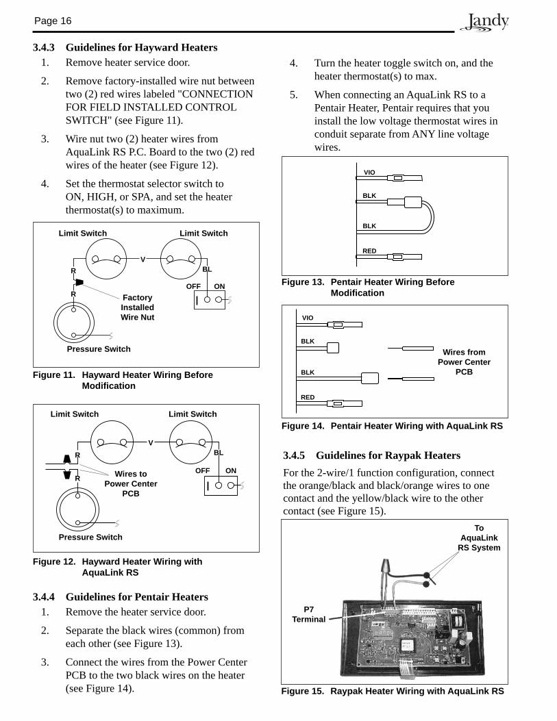
3.4.3 Guidelines for Hayward Heaters1. Remove heater service door.
2. Remove factory-installed wire nut between two (2) red wires labeled "CONNECTION FOR FIELD IN STALLED CONTROL SWITCH" (see Figure 11).
3. Wire nut two (2) heater wires from AquaLink RS P.C. Board to the two (2) red wires of the heater (see Figure 12).
4. Set the thermostat selector switch to ON, HIGH, or SPA, and set the heater thermostat(s) to maximum.
3.4.4 Guidelines for Pentair Heaters1. Remove the heater service door.
2. Separate the black wires (common) from each other (see Figure 13).
3. Connect the wires from the Power Center PCB to the two black wires on the heater (see Figure 14).
3.4.5 Guidelines for Raypak HeatersFor the 2-wire/1 function configuration, connect the orange/black and black/orange wires to one contact and the yellow/black wire to the other contact (see Figure 15).
Limit Switch
Factory Installed Wire Nut
R
Limit Switch
R
V
OFF ON
BL
Pressure Switch
Figure 11. Hayward Heater Wiring Before Modifi cation
Limit Switch
OFF ON
BL
Limit Switch
R
R
V
Pressure Switch
Wires to Power Center
PCB
Figure 12. Hayward Heater Wiring with AquaLink RS
Figure 13. Pentair Heater Wiring Before Mod i fi ca tion
VIO
BLK
BLK
RED
Figure 14. Pentair Heater Wiring with AquaLink RS
Wires from Power Center
PCB
VIO
BLK
BLK
RED
Figure 15. Raypak Heater Wiring with AquaLink RS
P7Terminal
ToAquaLink
RS System
4. Turn the heater toggle switch on, and the heater thermostat(s) to max.
5. When connecting an AquaLink RS to a Pentair Heater, Pentair requires that you install the low voltage thermostat wires in conduit separate from ANY line voltage wires.
Page 17
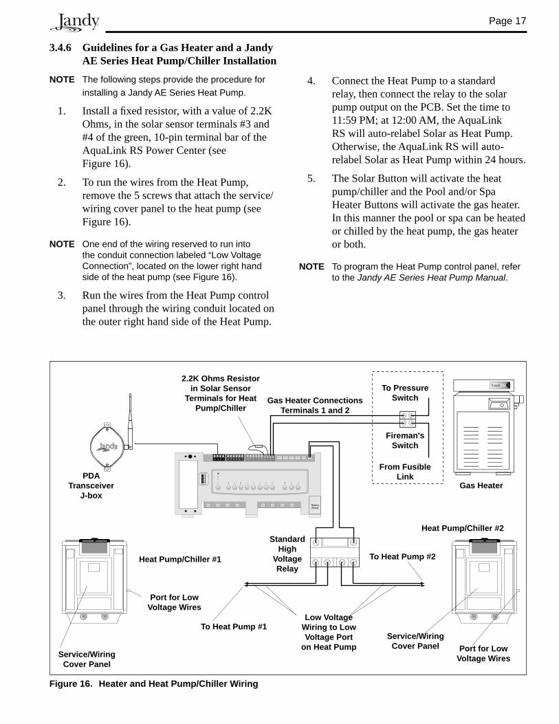
3.4.6 Guidelines for a Gas Heater and a Jandy AE Series Heat Pump/Chiller Installation
NOTE The following steps provide the procedure for installing a Jandy AE Series Heat Pump.
1. Install a fi xed resistor, with a value of 2.2K Ohms, in the solar sensor terminals #3 and #4 of the green, 10-pin terminal bar of the AquaLink RS Power Center (see Figure 16).
2. To run the wires from the Heat Pump, remove the 5 screws that attach the service/wiring cover panel to the heat pump (see Figure 16).
NOTE One end of the wiring reserved to run into the conduit connection labeled “Low Voltage Connection”, located on the lower right hand side of the heat pump (see Figure 16).
3. Run the wires from the Heat Pump control panel through the wiring conduit located on the outer right hand side of the Heat Pump.
4. Connect the Heat Pump to a standard relay, then connect the relay to the solar pump output on the PCB. Set the time to 11:59 PM; at 12:00 AM, the AquaLink RS will auto-relabel Solar as Heat Pump. Otherwise, the AquaLink RS will auto-relabel Solar as Heat Pump within 24 hours.
5. The Solar Button will activate the heat pump/chiller and the Pool and/or Spa Heater Buttons will activate the gas heater. In this manner the pool or spa can be heated or chilled by the heat pump, the gas heater or both.
NOTE To program the Heat Pump control panel, refer to the Jandy AE Series Heat Pump Manual.
Figure 16. Heater and Heat Pump/Chiller Wiring
4 3 2 1 6 5 4 3 2 1 10 9 8 7 6 5 4 3 2 1
Battery(9Volt)
Gas Heater
Heat Pump/Chiller #2
Service/WiringCover Panel
Fireman's Switch
From Fusible Link
To Pressure Switch
Port for Low Voltage Wires
Standard High
Voltage Relay
Heat Pump/Chiller #1
Gas Heater Connections Terminals 1 and 2
2.2K Ohms Resistor in Solar Sensor
Terminals for Heat Pump/Chiller
Low Voltage Wiring to Low Voltage Port
on Heat PumpService/Wiring
Cover Panel
Port for Low Voltage Wires
PDATransceiver
J-box
To Heat Pump #1
To Heat Pump #2
Page 18
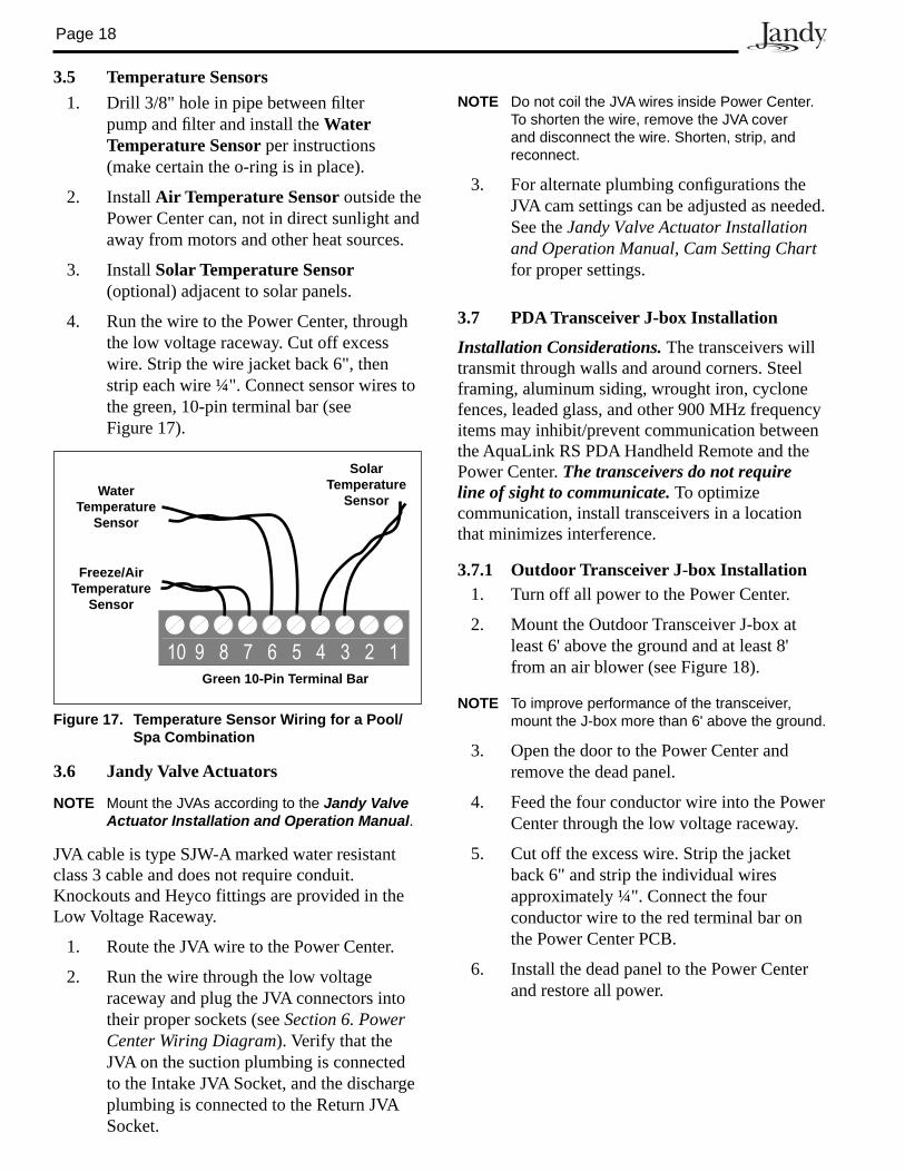
3.5 Temperature Sensors1. Drill 3/8" hole in pipe between fi lter
pump and fi lter and install the Water Temperature Sensor per instructions (make certain the o-ring is in place).
2. Install Air Temperature Sensor outside the Power Center can, not in direct sunlight and away from motors and other heat sources.
3. Install Solar Temperature Sensor (optional) adjacent to solar panels.
4. Run the wire to the Power Center, through the low voltage raceway. Cut off excess wire. Strip the wire jacket back 6", then strip each wire ¼". Connect sensor wires to the green, 10-pin terminal bar (see Figure 17).
3.6 Jandy Valve Actuators
NOTE Mount the JVAs according to the Jandy Valve Actuator Installation and Operation Manual.
JVA cable is type SJW-A marked water resistant class 3 cable and does not require conduit. Knockouts and Heyco fittings are provided in the Low Voltage Raceway.
1. Route the JVA wire to the Power Center.
2. Run the wire through the low voltage raceway and plug the JVA connectors into their proper sockets (see Section 6. Power Center Wiring Diagram). Verify that the JVA on the suction plumbing is connected to the Intake JVA Socket, and the discharge plumbing is connected to the Return JVA Socket.
Figure 17. Temperature Sensor Wiring for a Pool/Spa Combination
Water Temperature
Sensor
Freeze/Air Temperature
Sensor
Solar Temperature
Sensor
Green 10-Pin Terminal Bar
10 9 8 7 6 5 4 3 2 1
NOTE Do not coil the JVA wires inside Power Center. To shorten the wire, remove the JVA cover and disconnect the wire. Shorten, strip, and reconnect.
3. For alternate plumbing confi gurations the JVA cam settings can be adjusted as needed. See the Jandy Valve Actuator Installation and Operation Manual, Cam Setting Chart for proper settings.
3.7 PDA Transceiver J-box Installation
Installation Considerations. The transceivers will transmit through walls and around corners. Steel framing, aluminum siding, wrought iron, cyclone fences, lead ed glass, and other 900 MHz frequency items may inhibit/prevent com mu ni ca tion between the AquaL ink RS PDA Handheld Remote and the Power Center. The trans ceiv ers do not require line of sight to communicate. To optimize communication, install trans ceiv ers in a location that minimizes interference.
3.7.1 Outdoor Transceiver J-box Installation 1. Turn off all power to the Power Center.
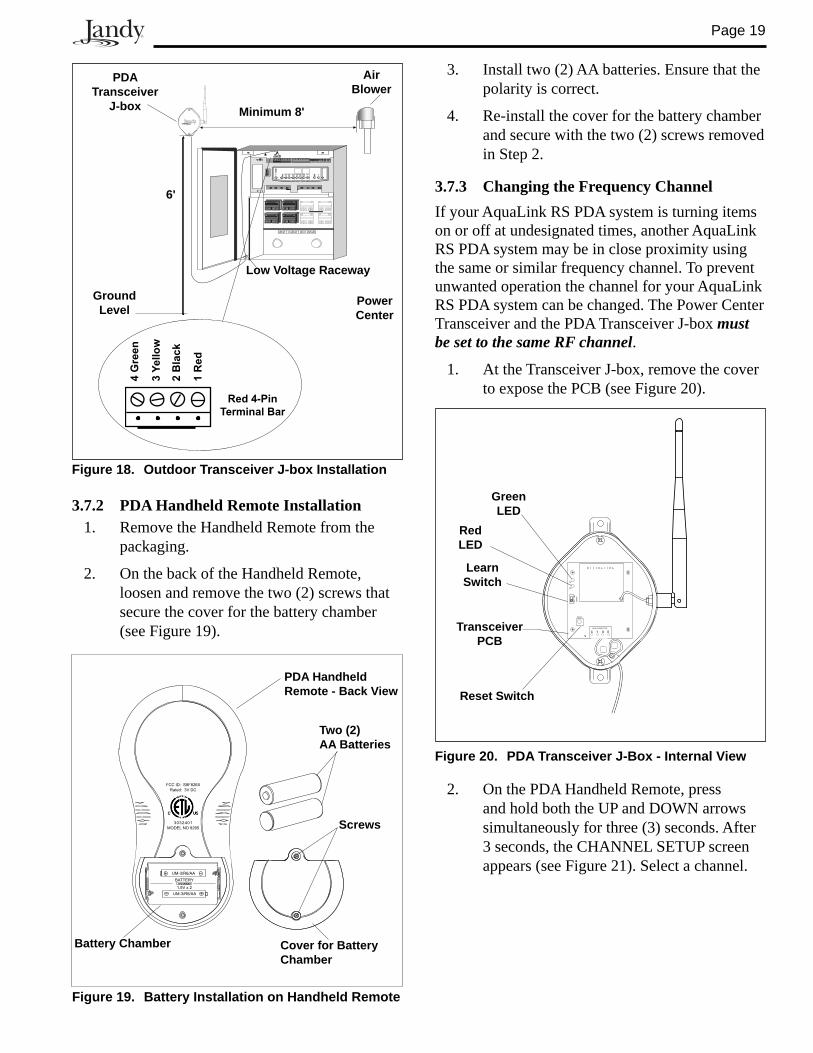
2. Mount the Outdoor Transceiver J-box at least 6' above the ground and at least 8' from an air blower (see Figure 18).
NOTE To improve performance of the transceiver, mount the J-box more than 6' above the ground.
3. Open the door to the Power Center and remove the dead panel.
4. Feed the four conductor wire into the Power Center through the low volt age raceway.
5. Cut off the excess wire. Strip the jacket back 6" and strip the individual wires approximately ¼". Connect the four conductor wire to the red terminal bar on the Power Center PCB.
6. Install the dead panel to the Power Center and restore all power.
Page 19
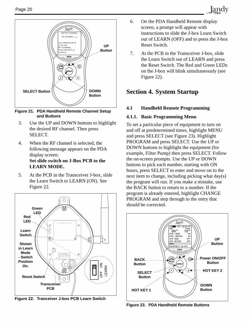
3.7.2 PDA Handheld Remote Installation 1. Remove the Handheld Remote from the
packaging.
2. On the back of the Handheld Remote, loosen and remove the two (2) screws that secure the cover for the battery chamber (see Figure 19).
3. Install two (2) AA batteries. Ensure that the polarity is correct.
4. Re-install the cover for the battery chamber and secure with the two (2) screws removed in Step 2.
3.7.3 Changing the Frequency ChannelIf your AquaLink RS PDA system is turning items on or off at undesignated times, another AquaLink RS PDA system may be in close proximity using the same or similar frequency channel. To prevent unwanted operation the channel for your AquaLink RS PDA system can be changed. The Power Center Trans ceiv er and the PDA Transceiver J-box must be set to the same RF channel.
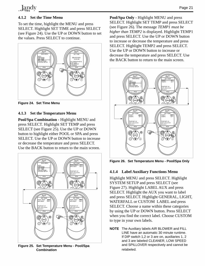
1. At the Transceiver J-box, remove the cover to expose the PCB (see Figure 20).
Figure 20. PDA Transceiver J-Box - Internal View
2. On the PDA Handheld Remote, press and hold both the UP and DOWN arrows simultaneously for three (3) seconds. After 3 seconds, the CHANNEL SETUP screen appears (see Figure 21). Select a channel.
Figure 19. Battery Installation on Handheld Remote
UM-3/R6/AA
UM-3/R6/AA
BATTERY
1.5V x 2
3032401
MODEL NO 8265
FCC ID: S8F826X
Rated: 3V DC
PDA Handheld Remote - Back View
Two (2) AA Batteries
Battery Chamber Cover for Battery Chamber
Screws
MAIN CONNECTOR
RESET
D2
D3
LE
AR
N
Y B RG
OF
FO
N
Transceiver PCB
Reset Switch
Learn Switch
Green LED
Red LED
Low Voltage Raceway
Power Center
Air Blower
PDA Trans ceiv er
J-box
6'
Minimum 8'
Ground Level
Figure 18. Outdoor Transceiver J-box Installation
3Y
ello
w
1R
ed
2B
lac
k
4G
ree
n
Red 4-Pin
Terminal Bar
Page 20
Section 4. System Startup
4.1 Handheld Remote Programming
4.1.1. Basic Programming MenuTo set a particular piece of equipment to turn on and off at predetermined times, highlight MENU and press SELECT (see Figure 23). Highlight PROGRAM and press SELECT. Use the UP or DOWN buttons to highlight the equipment (for example, Filter Pump) then press SELECT. Follow the on-screen prompts. Use the UP or DOWN buttons to pick each number, starting with ON hours, press SE LECT to enter and move on to the next item to change, including picking what day(s) the program will run. If you make a mistake, use the BACK button to return to a number. If the program is already en tered, highlight CHANGE PROGRAM and step through to the entry that should be cor rect ed.
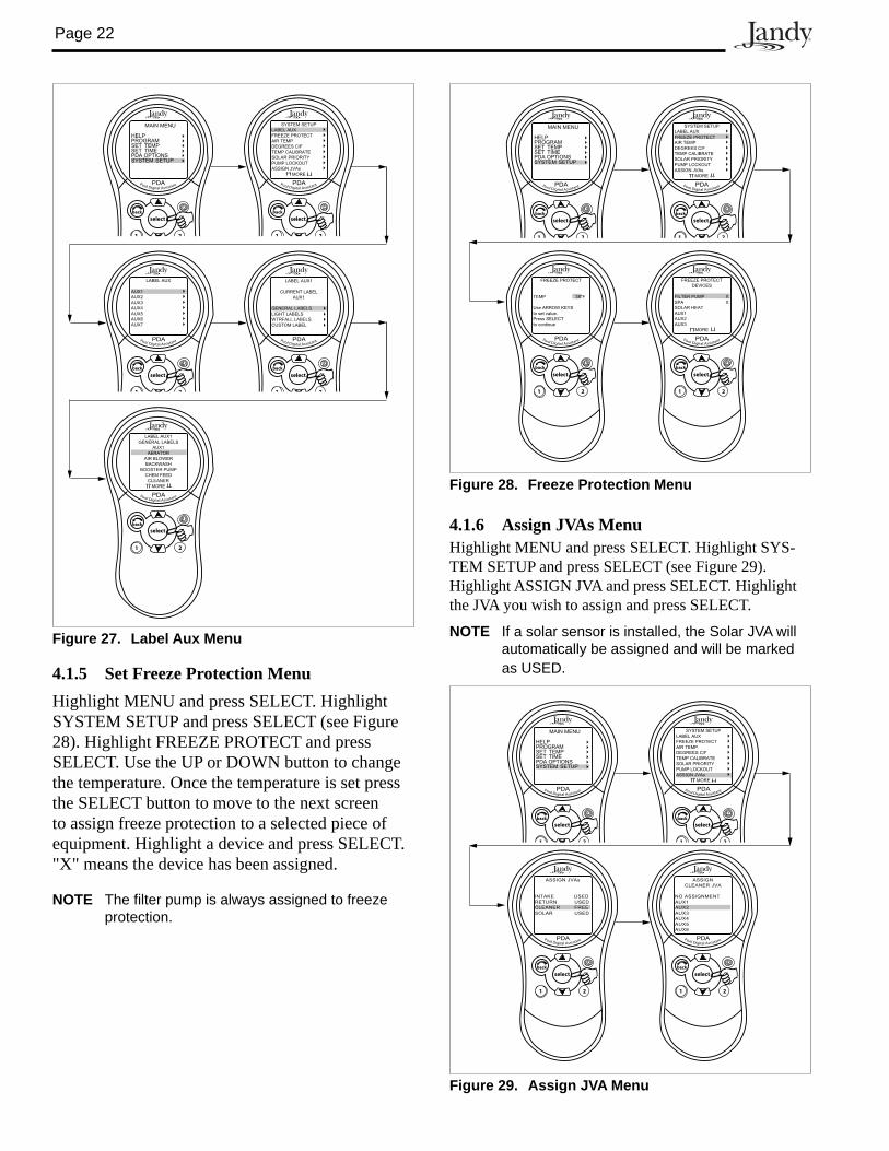
3. Use the UP and DOWN buttons to highlight the desired RF channel. Then press SELECT.
4. When the RF channel is selected, the following message appears on the PDA display screen:Set slide switch on J-Box PCB to the LEARN MODE.
5. At the PCB in the Transceiver J-box, slide the Learn Switch to LEARN (ON). See Figure 22.
SET RF CHANNEL
RF CHANNEL: 1
Use ARROW KEYS
to set the
RF CHANNEL.
Press SELECT to
continue.
Pool Digital Assistant
1 2
selectback
PDA
UP Button
DOWN Button
SELECT Button
Figure 21. PDA Handheld Remote Channel Setup and Buttons
Pool Digital Assistant
1 2
selectback
PDA
AIR POOL
78°80°POOL MODEPOOL HEATERSPA MODESPA HEATERMENUEQUIPMENT ON/OFF
ONON
OFFOFF
FRI 10:30 PM
Figure 23. PDA Handheld Remote Buttons
BACKButton
UP Button
DOWN Button
SELECTButton
HOT KEY 1
HOT KEY 2
Power ON/OFFButton
6. On the PDA Handheld Remote display screen, a prompt will appear with instructions to slide the J-box Learn Switch out of LEARN (OFF) and to press the J-box Reset Switch.
7. At the PCB in the Transceiver J-box, slide the Learn Switch out of LEARN and press the Reset Switch. The Red and Green LEDs on the J-box will blink simultaneously (see Figure 22).
Figure 22. Tranceiver J-box PCB Learn Switch
MAIN CONNECTOR
RESET
D2
D3
LE
AR
N
Y B RG
OF
FO
N
LE
AR
N
OF
FO
N
Transceiver PCB
Reset Switch
Learn Switch
Shown in Learn
Mode - Switch Position
On.
Green LED
Red LED
Page 21
4.1.2 Set the Time MenuTo set the time, highlight the MENU and press SELECT. Highlight SET TIME and press SELECT (see Figure 24). Use the UP or DOWN button to set the values. Press SELECT to continue.
Pool/Spa Only - Highlight MENU and press SELECT. Highlight SET TEMP and press SELECT (see Figure 26). The message TEMP1 must be higher than TEMP2 is displayed. Highlight TEMP1 and press SELECT. Use the UP or DOWN button to increase or decrease the temperature and press SELECT. Highlight TEMP2 and press SELECT. Use the UP or DOWN button to increase or decrease the temperature and press SELECT. Use the BACK button to return to the main screen.
SET TIME
2/14/05 MON10:00 AM
Use ARROW KEYSto set value.Press SELECTto continue.
Pool Digital Assistant
1 2
selectback
PDA
MAIN MENU
HELPPROGRAMSET TEMPSET TIMEPDA OPTIONSSYSTEM SETUP
Pool Digital Assistant
1 2
selectback
PDA
Figure 24. Set Time Menu
4.1.3 Set the Temperature MenuPool/Spa Combination - Highlight MENU and press SELECT. Highlight SET TEMP and press SELECT (see Figure 25). Use the UP or DOWN button to highlight either POOL or SPA and press SELECT. Use the UP or DOWN button to increase or decrease the tem per a ture and press SELECT. Use the BACK button to return to the main screen.
Pool Digital Assistant
1 2
selectback
PDA
MAIN MENU
HELPPROGRAMSET TEMPSET TIMEPDA OPTIONSSYSTEM SETUP
Pool Digital Assistant
1 2
selectback
PDA
SET TEMP
POOL HEAT 80°FSPA HEAT 104°F
Highlight anitem and pressSELECT
Pool Digital Assistant
1 2
selectback
PDA
SET TEMP
POOL HEAT 80°FSPA HEAT 104°F
Highlight anitem and pressSELECT
Pool Digital Assistant
1 2
selectback
PDA
SET TEMP
POOL HEAT 85°FSPA HEAT 104°F
Highlight anitem and pressSELECT
Figure 25. Set Temperature Menu - Pool/Spa Combination
Pool Digital Assistant
1 2
selectback
PDA
MAIN MENU
HELPPROGRAMSET TEMPSET TIMEPDA OPTIONSSYSTEM SETUP
Pool Digital Assistant
1 2
selectback
PDA
SET TEMP
TEMP1 80°FTEMP2 60°F
Highlight anitem and pressSELECT
Pool Digital Assistant
1 2
selectback
PDA
SET TEMP
TEMP1 80°FTEMP2 60°F
Highlight anitem and pressSELECT
Pool Digital Assistant
1 2
selectback
PDA
SET TEMP
TEMP1 85°FTEMP2 60°F
Highlight anitem and pressSELECT
Figure 26. Set Temperature Menu - Pool/Spa Only
4.1.4 Label Auxiliary Functions MenuHighlight MENU and press SELECT. Highlight SYS TEM SETUP and press SELECT (see Figure 27). Highlight LABEL AUX and press SELECT. High light the AUX you want to label and press SELECT. Highlight GENERAL, LIGHT, WA TER FALL or CUSTOM LABEL and press SELECT. Choose a name within these categories by using the UP or DOWN button. Press SELECT when you find the correct label. Choose CUS TOM to type in your own labels.
NOTE The Auxiliary labels AIR BLOWER and FILL LINE have an automatic 30 minute runtime. If DIP switch 1,2 or 3 are on, auxiliaries 1, 2 and 3 are labeled CLEANER, LOW SPEED and SP ILL OVER respectively and cannot be re la beled.
Page 22
4.1.5 Set Freeze Protection MenuHighlight MENU and press SELECT. Highlight SYSTEM SETUP and press SELECT (see Figure 28). Highlight FREEZE PROTECT and press SELECT. Use the UP or DOWN button to change the temperature. Once the temperature is set press the SELECT button to move to the next screen to assign freeze protection to a selected piece of equip ment. Highlight a device and press SELECT. "X" means the device has been assigned.
NOTE The filter pump is always assigned to freeze protection.
4.1.6 Assign JVAs MenuHighlight MENU and press SELECT. Highlight SYS-TEM SETUP and press SELECT (see Figure 29). Highlight ASSIGN JVA and press SELECT. Highlight the JVA you wish to assign and press SELECT. NOTE If a solar sensor is installed, the Solar JVA will
automatically be assigned and will be marked as USED.
MAIN MENU
HELPPROGRAMSET TEMPSET TIMEPDA OPTIONSSYSTEM SETUP
Pool Digital Assistant
1 2
selectback
PDA
SYSTEM SETUP
LABEL AUX
FREEZE PROTECT
AIR TEMP
DEGREES C/F
TEMP CALIBRATE
SOLAR PRIORITY
PUMP LOCKOUT
ASSIGN JVAs
MORE
Pool Digital Assistant
1 2
selectback
PDA
Pool Digital Assistant
1 2
selectback
PDA
LABEL AUX1
CURRENT LABEL
AUX1
GENERAL LABELS
LIGHT LABELS
WTRFALL LABELS
CUSTOM LABEL
Pool Digital Assistant
1 2
selectback
PDA
LABEL AUX1
GENERAL LABELS
AUX1
AERATOR
AIR BLOWER
BACKWASH
BOOSTER PUMP
CHEM FEED
CLEANER
MORE
Pool Digital Assistant
1 2
selectback
PDA
LABEL AUX
AUX1
AUX2
AUX3
AUX4
AUX5
AUX6
AUX7
Figure 27. Label Aux Menu
MAIN MENU
HELPPROGRAMSET TEMPSET TIMEPDA OPTIONSSYSTEM SETUP
Pool Digital Assistant
1 2
selectback
PDA
SYSTEM SETUP
LABEL AUX
FREEZE PROTECT
AIR TEMP
DEGREES C/F
TEMP CALIBRATE
SOLAR PRIORITY
PUMP LOCKOUT
ASSIGN JVAs
MORE
Pool Digital Assistant
1 2
selectback
PDA
Pool Digital Assistant
1 2
selectback
PDA
FREEZE PROTECT
DEVICES
FILTER PUMP X
SPA X
SOLAR HEAT
AUX1
AUX2
AUX3
MORE
Pool Digital Assistant
1 2
selectback
PDA
FREEZE PROTECT
TEMP 38°F
Use ARROW KEYS
to set value.
Press SELECT
to continue
Figure 28. Freeze Protection Menu
MAIN MENU
HELPPROGRAMSET TEMPSET TIMEPDA OPTIONSSYSTEM SETUP
Pool Digital Assistant
1 2
selectback
PDA
SYSTEM SETUP
LABEL AUX
FREEZE PROTECT
AIR TEMP
DEGREES C/F
TEMP CALIBRATE
SOLAR PRIORITY
PUMP LOCKOUT
ASSIGN JVAs
MORE
Pool Digital Assistant
1 2
selectback
PDA
ASSIGN JVAs
INTAKE USED
RETURN USED
CLEANER FREE
SOLAR USED
Pool Digital Assistant
1 2
selectback
PDA
ASSIGN
CLEANER JVA
NO ASSIGNMENT
AUX1
AUX2
AUX3
AUX4
AUX5
AUX6
Pool Digital Assistant
1 2
selectback
PDA
Figure 29. Assign JVA Menu
Page 23
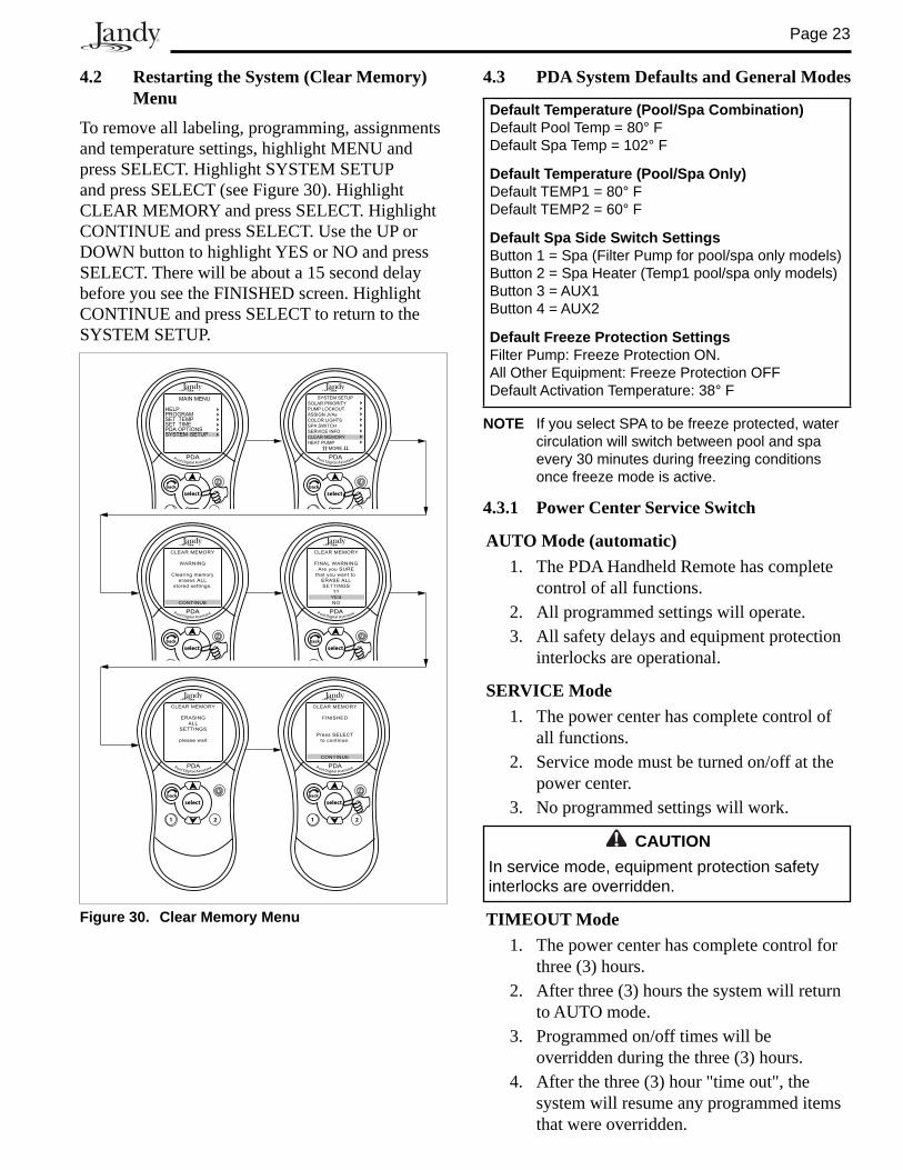
4.2 Restarting the System (Clear Memory) Menu
To remove all labeling, programming, assignments and temperature settings, highlight MENU and press SELECT. Highlight SYSTEM SETUP and press SELECT (see Figure 30). Highlight CLEAR MEMORY and press SELECT. Highlight CONTINUE and press SELECT. Use the UP or DOWN button to highlight YES or NO and press SELECT. There will be about a 15 second delay before you see the FINISHED screen. Highlight CONTINUE and press SELECT to return to the SYS TEM SETUP.
CAUTIONIn service mode, equipment protection safety interlocks are overridden.
MAIN MENU
HELPPROGRAMSET TEMPSET TIMEPDA OPTIONSSYSTEM SETUP
Pool Digital Assistant
1 2
selectback
PDA
SYSTEM SETUP
SOLAR PRIORITY
PUMP LOCKOUT
ASSIGN JVAs
COLOR LIGHTS
SPA SWITCH
SERVICE INFO
CLEAR MEMORY
HEAT PUMP
MORE
Pool Digital Assistant
1 2
selectback
PDA
CLEAR MEMORY
WARNING
Clearing memory
erases ALL
stored settings.
CONTINUE
Pool Digital Assistant
1 2
selectback
PDA
CLEAR MEMORY
FINAL WARNING
Are you SURE
that you want to
ERASE ALL
SETTINGS
??
YES
NO
Pool Digital Assistant
1 2
selectback
PDA
CLEAR MEMORY
FINISHED
Press SELECT
to continue.
CONTINUE
Pool Digital Assistant
1 2
selectback
PDAPool Digital Assistant
1 2
selectback
PDA
CLEAR MEMORY
ERASING
ALL
SETTINGS
please wait
Figure 30. Clear Memory Menu
4.3 PDA System Defaults and General Modes
Default Temperature (Pool/Spa Combination)Default Pool Temp = 80° FDefault Spa Temp = 102° F
Default Temperature (Pool/Spa Only)Default TEMP1 = 80° FDefault TEMP2 = 60° F
Default Spa Side Switch SettingsButton 1 = Spa (Filter Pump for pool/spa only models)Button 2 = Spa Heater (Temp1 pool/spa only models)Button 3 = AUX1Button 4 = AUX2
Default Freeze Protection SettingsFilter Pump: Freeze Protection ON. All Other Equipment: Freeze Protection OFFDefault Activation Temperature: 38° F
NOTE If you select SPA to be freeze protected, water circulation will switch between pool and spa every 30 minutes during freezing conditions once freeze mode is active.
4.3.1 Power Center Service Switch
AUTO Mode (automatic) 1. The PDA Handheld Remote has complete
control of all functions. 2. All programmed settings will operate. 3. All safety delays and equipment protection
in ter locks are operational.
SERVICE Mode1. The power center has complete control of
all functions. 2. Service mode must be turned on/off at the
power center. 3. No programmed settings will work.
TIMEOUT Mode1. The power center has complete control for
three (3) hours. 2. After three (3) hours the system will return
to AUTO mode. 3. Programmed on/off times will be
overridden during the three (3) hours.4. After the three (3) hour "time out", the
system will resume any programmed items that were overridden.
Page 24
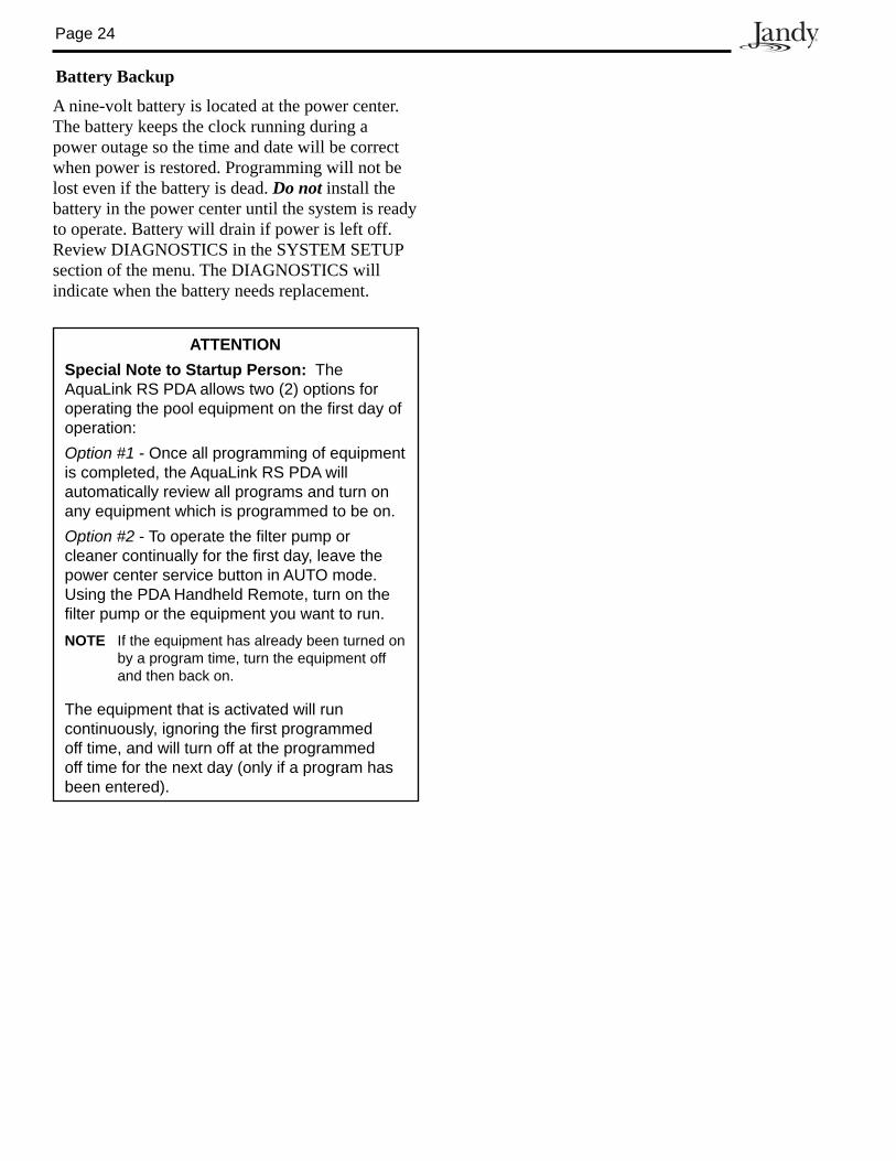
Battery Backup
A nine-volt battery is located at the power center. The battery keeps the clock running during a power outage so the time and date will be correct when power is restored. Programming will not be lost even if the battery is dead. Do not install the battery in the power center until the system is ready to operate. Battery will drain if power is left off. Review DI AG NOS TICS in the SYSTEM SETUP section of the menu. The DIAGNOSTICS will indicate when the battery needs replacement.
ATTENTIONSpecial Note to Startup Person: The AquaLink RS PDA allows two (2) options for operating the pool equipment on the first day of operation:Option #1 - Once all programming of equipment is completed, the AquaLink RS PDA will automatically review all programs and turn on any equipment which is programmed to be on. Option #2 - To operate the filter pump or cleaner continually for the first day, leave the power center service button in AUTO mode. Using the PDA Handheld Remote, turn on the filter pump or the equip ment you want to run.NOTE If the equipment has already been turned on
by a program time, turn the equipment off and then back on.
The equipment that is ac ti vat ed will run con tin u ous ly, ignoring the first programmed off time, and will turn off at the programmed off time for the next day (only if a program has been entered).
Page 25
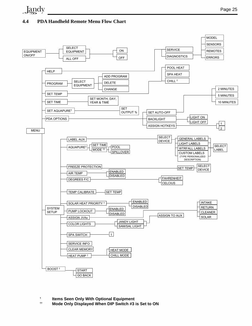
4.4 PDA Handheld Remote Menu Flow Chart
MENU
PROGRAM
SET TEMP
POOL HEAT
SPA HEAT
SET TIMESET MONTH, DAY,
YEAR & TIME
PDA OPTIONS
SET AUTO-OFF
BACKLIGHT
ASSIGN HOTKEYS
SYSTEM
SETUP
LABEL AUX
TEMP CALIBRATE
SOLAR HEAT PRIORITY †
ASSIGN JVAs
SPA SWITCH
SERVICE INFO
CLEAR MEMORY
GENERAL LABELS
LIGHT LABELS
WTRFALL LABELS
(TYPE PERSONALIZED
DESCRIPTION)
INTAKE
RETURN
CLEANER
SOLAR
1
ENABLED
DISABLED
SET TEMP
FREEZE PROTECTION
AIR TEMP
DEGREES F/C
ENABLED
DISABLEDFAHRENHEIT
CELCIUS
SET TEMP
PUMP LOCKOUTENABLED
DISABLED
BOOST †
SET AQUAPURE†SET
OUTPUT %
AQUAPURE†SET TIME
HELP
SERVICE
DIAGNOSTICS
START
GO BACK
EQUIPMENT
ON/OFF
SELECT
EQUIPMENT ON
OFFALL OFF
ADD PROGRAM
DELETE
CHANGE
CHILL †
MODEL
SENSORS
REMOTES
ERRORS
MODE ††POOL
SPILLOVER
COLOR LIGHTSJANDY LIGHT
SAM/SAL LIGHT
ASSIGN TO AUX
SELECT
EQUIPMENT
SELECT
DEVICE
SELECT
DEVICE
SELECT
LABELCUSTOM LABELS
HEAT PUMP †
HEAT MODE
CHILL MODE
LIGHT ON
LIGHT OFF
2 MINUTES
5 MINUTES
10 MINUTES
1
2
† Items Seen Only With Optional Equipment †† Mode Only Displayed When DIP Switch #3 is Set to ON
Page 26
Section 5. Troubleshooting
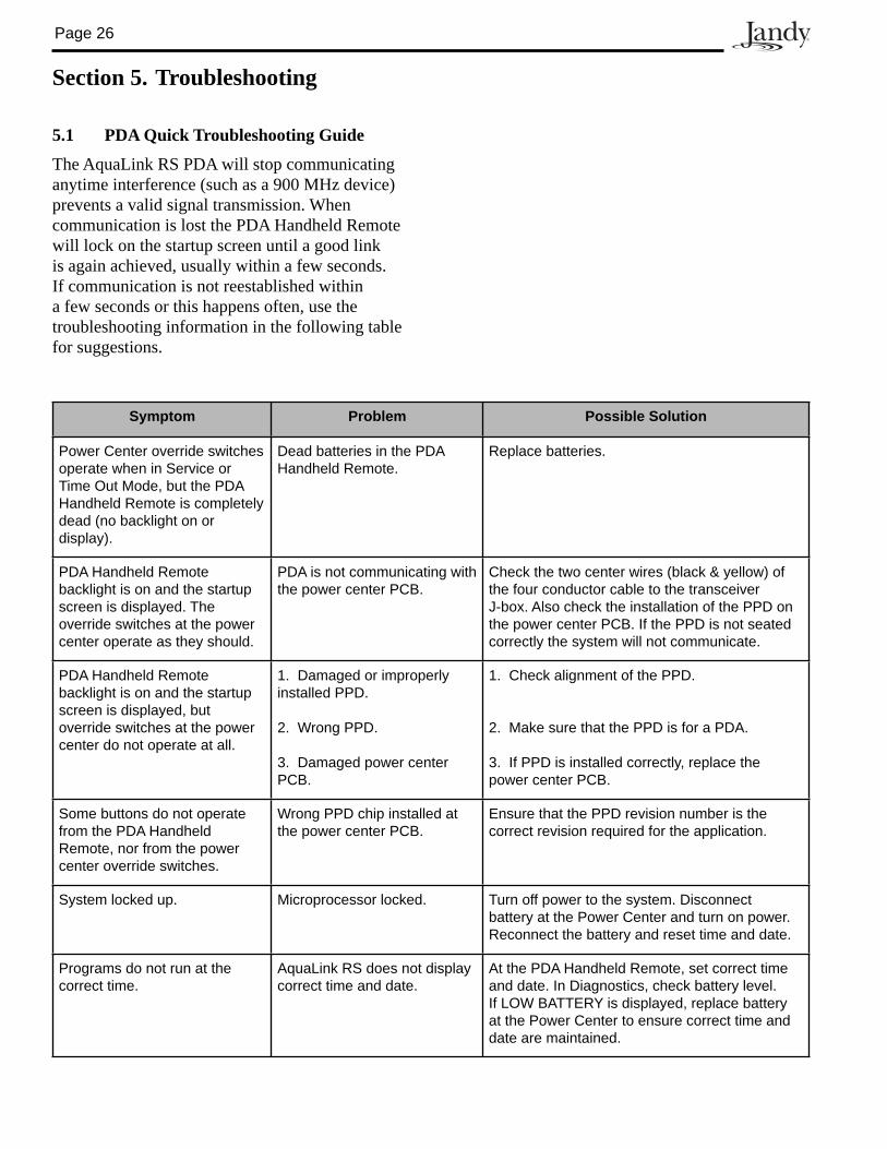
5.1 PDA Quick Troubleshooting Guide
The AquaLink RS PDA will stop communicating anytime interference (such as a 900 MHz device) prevents a valid signal transmission. When communication is lost the PDA Handheld Remote will lock on the startup screen until a good link is again achieved, usually within a few sec onds. If com mu ni ca tion is not reestablished within a few seconds or this happens often, use the troubleshooting in for ma tion in the following table for suggestions.
Symptom Problem Possible Solution
Power Center override switches operate when in Service or Time Out Mode, but the PDA Handheld Remote is completely dead (no backlight on or display).
Dead batteries in the PDA Handheld Remote.
Replace batteries.
PDA Handheld Remote backlight is on and the startup screen is displayed. The override switches at the power center operate as they should.
PDA is not communicating with the power center PCB.
Check the two center wires (black & yellow) of the four conductor cable to the transceiver J-box. Also check the installation of the PPD on the power center PCB. If the PPD is not seated correctly the system will not communicate.
PDA Handheld Remote backlight is on and the startup screen is displayed, but override switch es at the power center do not operate at all.
1. Damaged or improperly installed PPD.
2. Wrong PPD.
3. Damaged power center PCB.
1. Check alignment of the PPD.
2. Make sure that the PPD is for a PDA.
3. If PPD is installed correctly, replace the power center PCB.
Some buttons do not operate from the PDA Handheld Remote, nor from the power center override switches.
Wrong PPD chip installed at the power center PCB.
Ensure that the PPD revision number is the correct revision required for the application.
System locked up. Microprocessor locked. Turn off power to the system. Disconnect battery at the Power Center and turn on power. Reconnect the battery and reset time and date.
Programs do not run at the correct time.
AquaLink RS does not display correct time and date.
At the PDA Handheld Remote, set correct time and date. In Diagnostics, check battery level. If LOW BATTERY is displayed, replace battery at the Power Center to ensure correct time and date are maintained.
Page 27
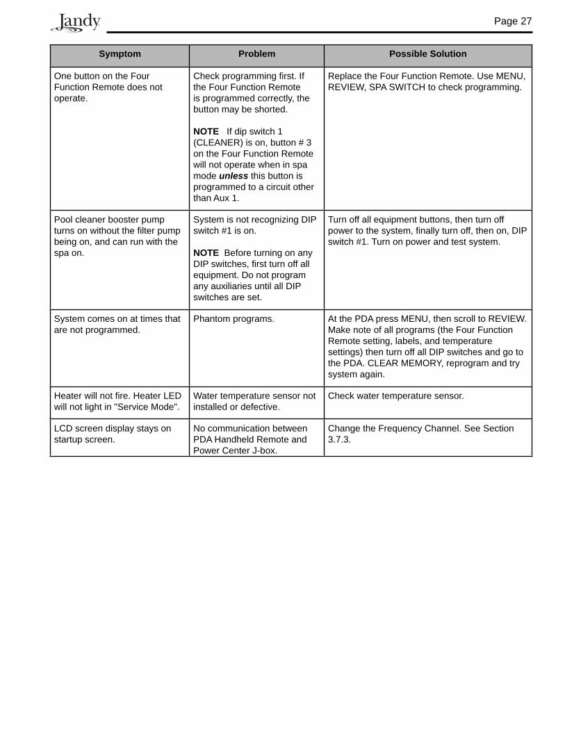
Symptom Problem Possible Solution
One button on the Four Function Remote does not operate.
Check programming first. If the Four Function Remote is programmed correctly, the button may be shorted.
NOTE If dip switch 1 (CLEANER) is on, button # 3 on the Four Function Remote will not operate when in spa mode unless this button is programmed to a circuit other than Aux 1.
Replace the Four Function Re mote. Use MENU, REVIEW, SPA SWITCH to check pro gram ming.
Pool cleaner booster pump turns on without the filter pump being on, and can run with the spa on.
System is not recognizing DIP switch #1 is on.
NOTE Before turning on any DIP switches, first turn off all equipment. Do not program any auxiliaries until all DIP switches are set.
Turn off all equipment buttons, then turn off power to the system, finally turn off, then on, DIP switch #1. Turn on power and test system.
System comes on at times that are not programmed.
Phantom programs. At the PDA press MENU, then scroll to REVIEW. Make note of all programs (the Four Function Remote setting, labels, and temperature settings) then turn off all DIP switches and go to the PDA. CLEAR MEM O RY, reprogram and try system again.
Heater will not fire. Heater LED will not light in "Service Mode".
Water temperature sensor not installed or defective.
Check water temperature sensor.
LCD screen display stays on startup screen.
No communication between PDA Handheld Remote and Power Center J-box.
Change the Frequency Channel. See Section 3.7.3.
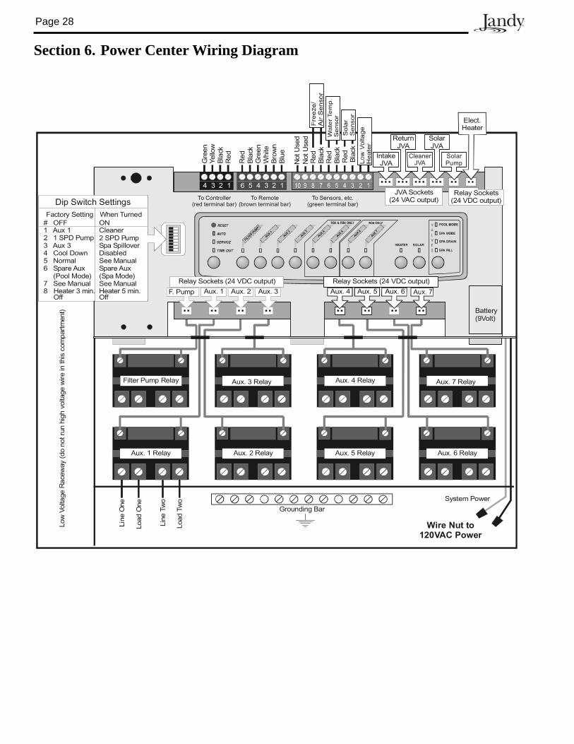
Page 28
Section 6. Power Center Wiring Diagram
Aux. 4 Relay Aux. 7 Relay
Aux. 5 Relay Aux. 6 Relay
Filter Pump Relay Aux. 3 Relay
Aux. 1 Relay
Line
One
Low
Volta
geR
acew
ay(d
ono
trun
high
volta
gew
irein
this
com
part
men
t)
Line
Two
Load
One
Load
Two
Aux. 2 Relay
Grounding Bar
Wire Nut to120VAC Power
System Power
IntakeJVA
CleanerJVA
SolarPump
ReturnJVA
SolarJVA
Elect.Heater
Red
Bla
ckG
reen
Whi
te
Yello
wG
reen
Bla
ckR
ed
Bro
wn
To Remote(brown terminal bar)
To Sensors, etc.(green terminal bar)
To Controller(red terminal bar)
4 3 2 1 6 5 4 3 2 1
Blu
e
Red
Bla
ckR
edB
lack
F. Pump Aux. 2 Aux. 3 Aux. 6Aux. 5Aux. 4
Relay Sockets(24 VDC output)
JVA Sockets(24 VAC output)
# OFF1 Aux 12 1 SPD Pump3 Aux 34 Cool Down5 Normal6 Spare Aux
(Pool Mode)7 See Manual8 Heater 3 min.
Off
Battery(9Volt)
Dip Switch SettingsFactory Setting
ONCleaner2 SPD PumpSpa SpilloverDisabledSee ManualSpare Aux(Spa Mode)See Manual
Red
Bla
ck
Not
Use
dN
otU
sed
FILTER
PUMP
AUX1
AUX
2
AUX
3
AUX4
AUX
5
AUX6
AUX
7
Relay Sockets (24 VDC output) Relay Sockets (24 VDC output)
When Turned
Heater 5 min.Off
Aux 1.
Page 29
Section 7. Power Center PCB DIP Switch Settings
IMPORTANT Do not program equipment ON/OFF times until all DIP switches are set.
7.1 DIP Switch FunctionsDIP #1 ON- AUX 1 Controls Pool CleanerIf you installed a booster pump for a pool cleaner, the relay coil for the booster pump must be plugged into the AUX 1 relay socket. If a non-booster pump cleaner is installed, plug the JVA into the cleaner JVA socket. Turn ON DIP Switch #1.
• Main fi lter pump turns on whenever cleaner turns on.
• Cleaner will not turn on until fi lter pump has been on for three (3) minutes (to ensure priming of system).
• Cleaner turns off when water circulation is to spa.
• Cleaner turns off when spa spillover feature is activated.
• Cleaner turns off for three (3) minutes when solar is activated (to ensure air is purged from the system).
• AquaLink RS PDA Handheld Remote display reads "CLEANER" rather than "AUX 1".
DIP #2 ON- AUX 2 Controls Low Speed of Filter Pump
Turn this switch ON if you want to control both speeds of a two-speed filter pump. With this switch on, the filter pump button on the AquaLink RS PDA will control high speed and the HOT KEY 2 (default) button will control low speed.
IMPORTANT You must also install a Jandy Two- Speed Relay.
DIP #3 ON- AUX 3 Controls Spa Spillover (Operates with Pool/Spa Combination)
Turn this switch ON, and when the AUX 3 button on the AquaLink RS PDA (or Spa Side Switch) is pressed, the Return Valve Actuator will rotate to spa cir cu la tion. Because the Intake Valve Actuator does not rotate, the spa will fill with water and overflow into the pool.
NOTE Leave AUX 3 relay socket empty.
CAUTIONTurn this DIP Switch ON only if you are using an electric heater or a heat pump that does not retain residual heat. If you are turning this switch ON for service pur pos es, be sure to turn it back off.
DIP #4 ON- Heater Cool Down DisabledTurn this switch ON to disable the heater cool down safety feature on the AquaLink RS.
DIP #5 ON- Factory Use OnlyThis switch is used for calibration by Jandy certified technicians only (will display the solar tem per a ture). Please leave this switch in the OFF po si tion.
DIP #6 ON - Pool/Spa Combination Systems OnlyChange Spare AUX to activate when Filter Pump is on and system is in spa mode. Spare AUX socket is on the back side of the Power Center PCB.
DIP #7 ON- Not Used
Dip #8 ON- Heat Pump Instead of Gas HeaterTurn this switch ON if you have installed a heat pump instead of a gas heater. After thermostat setting has been reached, heater will remain OFF for 5 minutes.
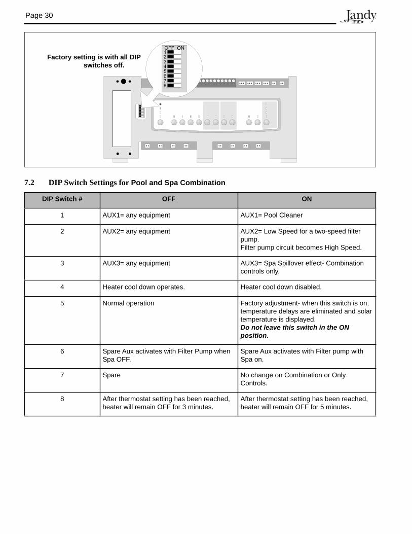
Page 30
7.2 DIP Switch Settings for Pool and Spa Combination
DIP Switch # OFF ON
1 AUX1= any equipment AUX1= Pool Cleaner
2 AUX2= any equipment AUX2= Low Speed for a two-speed filter pump.Filter pump circuit becomes High Speed.
3 AUX3= any equipment AUX3= Spa Spillover effect- Combination controls only.
4 Heater cool down operates. Heater cool down disabled.
5 Normal operation Factory adjustment- when this switch is on, temperature delays are eliminated and solar temperature is displayed. Do not leave this switch in the ON position.
6 Spare Aux activates with Filter Pump when Spa OFF.
Spare Aux activates with Filter pump with Spa on.
7 Spare No change on Combination or Only Controls.
8 After thermostat setting has been reached, heater will remain OFF for 3 minutes.
After thermostat setting has been reached, heater will remain OFF for 5 minutes.
Factory setting is with all DIP switches off.
1OFF ON
345678
2
Page 31
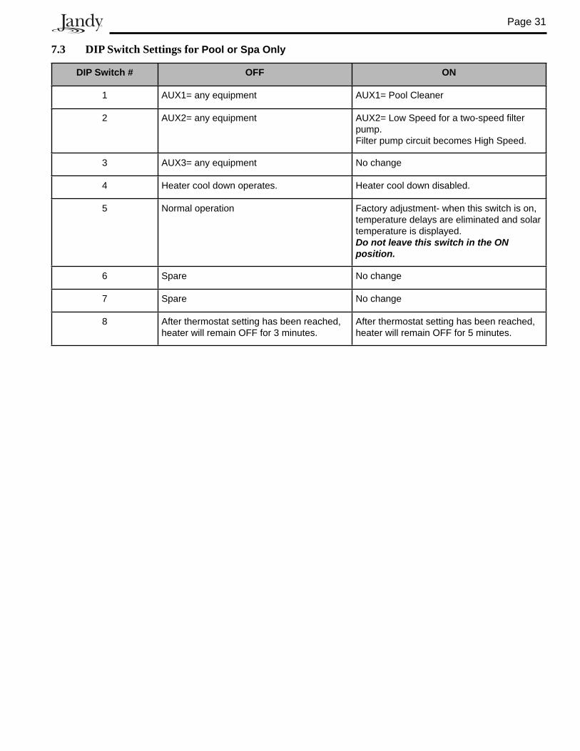
7.3 DIP Switch Settings for Pool or Spa Only
DIP Switch # OFF ON
1 AUX1= any equipment AUX1= Pool Cleaner
2 AUX2= any equipment AUX2= Low Speed for a two-speed filter pump.Filter pump circuit becomes High Speed.
3 AUX3= any equipment No change
4 Heater cool down operates. Heater cool down disabled.
5 Normal operation Factory adjustment- when this switch is on, temperature delays are eliminated and solar temperature is displayed. Do not leave this switch in the ON position.
6 Spare No change
7 Spare No change
8 After thermostat setting has been reached, heater will remain OFF for 3 minutes.
After thermostat setting has been reached, heater will remain OFF for 5 minutes.
Page 32
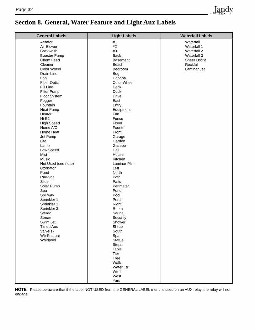
Section 8. General, Water Feature and Light Aux Labels
General Labels Light Labels Waterfall LabelsAeratorAir BlowerBackwashBooster PumpChem FeedCleanerColor WheelDrain LineFanFiber OpticFill LineFilter PumpFloor SystemFoggerFountainHeat PumpHeater Hi-E2High SpeedHome A/CHome HeatJet PumpLiteLampLow SpeedMistMusicNot Used (see note)OzonatorPondRay-VacSlideSolar PumpSpaSpillwaySprinkler 1Sprinkler 2Sprinkler 3StereoStreamSwim JetTimed AuxValve(s)Wtr FeatureWhirlpool
#1#2#3BackBasementBeachBedroomBugCabanaColor WheelDeckDockDriveEastEntryEquipmentFanFenceFloodFountnFrontGarageGardenGazeboHallHouseKitchenLaminar PlsrLeftNorthPathPatioPerimeterPondPoolPorchRightRoomSaunaSecurityShowerShrubSouthSpaStatueStepsTableTierTreeWalkWater FtrWtrfllWestYard
WaterfallWaterfall 1Waterfall 2Waterfall 3Sheer DscntRockfallLaminar Jet
NOTE Please be aware that if the label NOT USED from the GENERAL LABEL menu is used on an AUX relay, the relay will not engage.

Page 33
NOTES

Page 34
NOTES


LIMITED WARRANTYThank you for purchasing Jandy® pool and spa products. Jandy Pool Products, Inc. warrants all parts to be freefrom manufacturing defects in materials and workmanship for a period of one year from the date of retail purchase, with the following exceptions:
• AquaLink® RS units installed with Jandy Surge Protection Kits will be covered for two years.• NeverLube® valves are warranted for the life of pool and/or spa on which they were originally installed.• AquaPureTM Electronic Chlorine Generator Electrolytic Cells carry a 5 year limited warranty on a prorated basis.
This warranty is limited to the first retail purchaser, is not transferable, and does not apply to products that have been moved from their original installation sites. The liability of Jandy Pool Products, Inc. shall not exceed the repair or replacement of defective parts and does not include any costs for labor to remove and reinstall the defective part, transportation to or from the factory, and any other materials required to make the repair. This warranty does not cover failures or malfunctions resulting from the following:
1. Failure to properly install, operate or maintain the product(s) in accordance with our published Installation,Operation and Maintenance Manuals provided with the product(s).
2. The workmanship of any installer of the product(s).3. Not maintaining a proper chemical balance in your pool and/or spa [pH level between 7.2 and 7.8, Total
Alkalinity (TA) between 80 to 120 ppm, Total Dissolved Solids (TDS) less than 2000 not including salt ppm].4. Abuse, alteration, accident, fire, flood, lightning, rodents, insects, negligence or acts of God.5. Scaling, freezing, or other conditions causing inadequate water circulation.6. Operating the product(s) at water flow rates outside the published minimum and maximum specifications.7. Use of non-factory authorized parts or accessories in conjunction with the product(s).8. Chemical contamination of combustion air or improper use of sanitizing chemicals, such as introducing
sanitizing chemicals upstream of the heater and cleaner hose or through the skimmer.9. Overheating; incorrect wire runs; improper electrical supply; collateral damage caused by failure of O-Rings,
DE grids, or cartridge elements; or damage caused by running the pump with insufficient quantities of water.
LIMITATION OF LIABILITY:This is the only warranty given by Jandy Pool Products, Inc. No one is authorized to make any other warranties on behalf of Jandy Pool Products, Inc. THIS WARRANTY IS IN LIEU OF ALL OTHER WARRANTIES, EXPRESSED OR IMPLIED, INCLUDING BUT NOT LIMITED TO ANY IMPLIED WARRANTIES OF FITNESS FOR A PARTICULAR PURPOSE AND MERCHANTABILITY. JANDY POOL PRODUCTS, INC. EXPRESSLY DISCLAIMS AND EXCLUDES ANY LIABILITY FOR CONSEQUENTIAL, INCIDENTAL, INDIRECT OR PUNITIVE DAMAGES FOR BREACH OF ANY EXPRESSED OR IMPLIED WARRANTY. This warranty gives you specific legal rights. You may also have other rights which vary by state or province.
WARRANTY CLAIMS:For prompt warranty consideration, contact your dealer and provide the following information: proof of purchase, model number, serial number and date of installation. The installer will contact the factory for instructions regarding the claim and to determine the location of the nearest designated service center. If the dealer is not available, you can locate a service center in your area by visiting www.jandy.com or by calling our technical support department at (707) 776-8200 extension 260. All returned parts must have a Returned Material Authorization number to be evaluated under the terms of this warranty.
6000 Condor Drive • Moorpark, CA USA 93021 • 707.776.8200 • Fax 707.763.7785Jandy Pool Products, Inc
H05
7220
0A
ETL LISTEDCONFORMS TO
UL STD 1563
CERTIFIED TOCAN/CSA C22.2 NO. 218.1
PDA HANDHELD REMOTE FCC ID: S8F826X
PDA TRANSCEIVER FCC ID: S8F8252
Litho in U.S.A. © Jandy Pool Products, Inc. 0507