cover-pools /aqualink rs interface
TRANSCRIPT

Cover-Pools®/AquaLink® RS Interface
For use with AquaLink RS OneTouchTM Systems with Rev R Firmware or later and Cover-Pools Auto-Shutoff Controller
H037
0100
Rev
AINSTALLATION ANd
OPERATION MANuAL
WARNINGFOR YOUR SAFETY - This product must be installed and serviced by a contractor who is licensed and qualified in pool equipment by the jurisdiction in which the product will be installed where such state or local requirements exist. The maintainer must be a professional with sufficient experience in pool equipment installation and maintenance so that all of the instructions in this manual can be followed exactly. Before installing this product, read and follow all warning notices and instructions that accompany this product. Failure to follow warning notices and instructions may result in property damage, personal injury, or death. Improper installation and/or operation will void the warranty.Improper installation and/or operation can create unwanted electrical hazard which can cause serious injury, property damage, or death.

Page 2 ENGLISH Cover-Pools®/Aqualink® RS Interface | Installation and Operation Manual

Table of Contents
Section 1. Important Safety Instructions ........ 5
Section 2. System Overview ............................ 72.1 Cover-Pools/AquaLinkRSInterface................... 7
Section 3. Cover-Pools/AquaLink RS Interface Installation ....................... 7
3.1 PowerCenterBezelInstallation......................... 73.2 Low-VoltageRacewayInstallation...................... 83.3 WiringtheCover-Pools/AquaLinkRS
Interface............................................................. 8
Section 4. Cover-Pools/AquaLink RS Interface OneTouchTM Set up ....... 10
4.1 Cover-Pools/AquaLinkRSInterfaceSetUp..... 10
Page 3 ENGLISH Cover-Pools®/Aqualink® RS Interface | Installation and Operation Manual

Page 4 ENGLISH Cover-Pools®/Aqualink® RS Interface | Installation and Operation Manual
Section 1. Important Safety InstructionsREAd ANd FOLLOW ALL INSTRuCTIONS
All electrical work must be performed by a licensed electrician and conform to all national, state, and local codes. When installing and using this electrical equipment, basic safety precautions should always be followed, including the following:
WARNINGProlongedimmersioninhotwatermayinducehyperthermia.Hyperthermiaoccurswhentheinternaltemperatureofthebodyreachesalevelseveraldegreesabovethenormalbodytemperatureof98.6°F(37°C).Thesymptomsofhyperthermiaincludedizziness,fainting,drowsiness,lethargy,andanincreaseintheinternaltemperatureofthebody.Theeffectsofhyperthermiainclude:1)unawarenessofimpendingdanger;2)failuretoperceiveheat;3)failuretorecognizetheneedtoexitspa;4)physicalinabilitytoexitspa;5)fetaldamageinpregnantwomen;6)unconsciousnessresultinginadangerofdrowning.
dANGERToreducetheriskofinjury,donotremovethesuctionfittingsofyourspaorhottub.Neveroperateaspaorhottubifthesuctionfittingsarebrokenormissing.Neverreplaceasuctionfittingwithoneratedlessthantheflowratemarkedontheequipmentassembly.
WARNINGTo Reduce the Risk of Injury -a) Thewaterinaspashouldneverexceed104°F(40°C).Watertemperaturesbetween100°F(38°C)and104°F
(40°C)areconsideredsafeforahealthyadult.Lowerwatertemperaturesarerecommendedforyoungchildrenandwhenspauseexceeds10minutes.
b) Sinceexcessivewatertemperatureshaveahighpotentialforcausingfetaldamageduringtheearlymonthsofpregnancy,pregnantorpossiblypregnantwomenshouldlimitspawatertemperaturesto100°F(38°C).
c) Beforeenteringaspaorhottub,theusershouldmeasurethewatertemperaturewithanaccuratethermometersincethetoleranceofwatertemperature-regulatingdevicesvaries.
d) Theuseofalcohol,drugs,ormedicationbeforeorduringspaorhottubusemayleadtounconsciousnesswiththepossibilityofdrowning.
e) Obesepersonsandpersonswithahistoryofheartdisease,loworhighbloodpressure,circulatorysystemproblems,ordiabetesshouldconsultaphysicianbeforeusingaspa.
f) Personsusingmedicationshouldconsultaphysicianbeforeusingaspaorhottubsincesomemedicationmayinducedrowsineswhileothermedicationmayaffectheartrate,bloodpressure,andcirculation.
WARNINGRisk of electric shock - Installthepowercenteratleastfive(5)feet(152.4cm)fromtheinsidewallofthepooland/orhottubusingnon-metallicplumbing.Canadianinstallationsmustbeatleastthree(3)metersfromthewater.Childrenshouldnotusespasorhottubswithoutadultsupervision.Donotusespasorhottubsunlessallsuctionguardsareinstalledtopreventbodyandhairentrapment.Peopleusingmedicationsand/orhavinganadversemedicalhistoryshouldconsultaphysicianbeforeusingaspaorhottub.
Page 5 ENGLISH Cover-Pools®/Aqualink® RS Interface | Installation and Operation Manual

CAuTIONAground-faultcircuit-interruptermustbeprovidedifthisdeviceisusedtocontrolunderwaterlightingfixtures.Theconductorsontheloadsideoftheground-faultcircuit-interruptershallnotoccupyconduit,boxes,orenclosurescontainingotherconductorsunlesstheadditionalconductorsarealsoprotectedbyaground-faultcircuit-interrupter.Refertolocalcodesforcompletedetails.
CAuTIONAterminalbarmarked"GROUND"isprovidedwithinthepowercenter.Toreducetheriskofelectricalshock,connectthisterminalbartothegroundingterminalofyourelectricserviceorsupplypanelwithacontinuouscopperconductorhavinggreeninsulationandonethatisequivalentinsizetothecircuitconductorssupplyingthisequipment,butnosmallerthanno.12AWG(3.3mm).Inaddition,asecondwireconnectorshouldbebondedwithano.8AWG(4.115mm)copperwiretoanymetalladders,waterpipes,orothermetalwithinfive(5)feet(1.52m)ofthetub.
SAVE THESE INSTRuCTIONS
WARNINGPeoplewithinfectiousdiseasesshouldnotuseaspaorhottub.Toavoidinjury,exercisecarewhenenteringorexitingthespaorhottub.Donotusedrugsoralcoholbeforeorduringtheuseofaspaorhottubtoavoidunconsciousnessandpossibledrowning.Pregnantorpossiblypregnantwomenshouldconsultaphysicianbeforeusingaspaorhottub.Watertemperatureinexcessof100°F(38°C)maybeinjurioustoyourhealth.Beforeenteringaspaorhottubmeasurethewatertemperaturewithanaccuratethermometer.Donotuseaspaorhottubimmediatelyfollowingstrenuousexercise.Prolongedimmersioninaspaorhottubmaybeinjurioustoyourhealth.Donotpermitanyelectricappliance(suchasalight,telephone,radio,ortelevision)within5feet(1.5m)ofaspaorhottub.Theuseofalcohol,drugsormedicationcangreatlyincreasetheriskoffatalhyperthermiainhottubsandspas.Watertemperatureinexcessof100°F(38°C)maybehazardoustoyourhealth.
Attention installer: Installtoprovidedrainageofcompartmentforelectricalcomponents.
WARNINGToavoidinjuryensurethatyouusethiscontrolsystemtocontrolonlypackagedpool/spaheaterswhichhavebuilt-inoperatingandhighlimitcontrolstolimitwatertemperatureforpool/spaapplications.Thisdeviceshouldnotberelieduponasasafetylimitcontrol.
Page 6 ENGLISH Cover-Pools®/Aqualink® RS Interface | Installation and Operation Manual
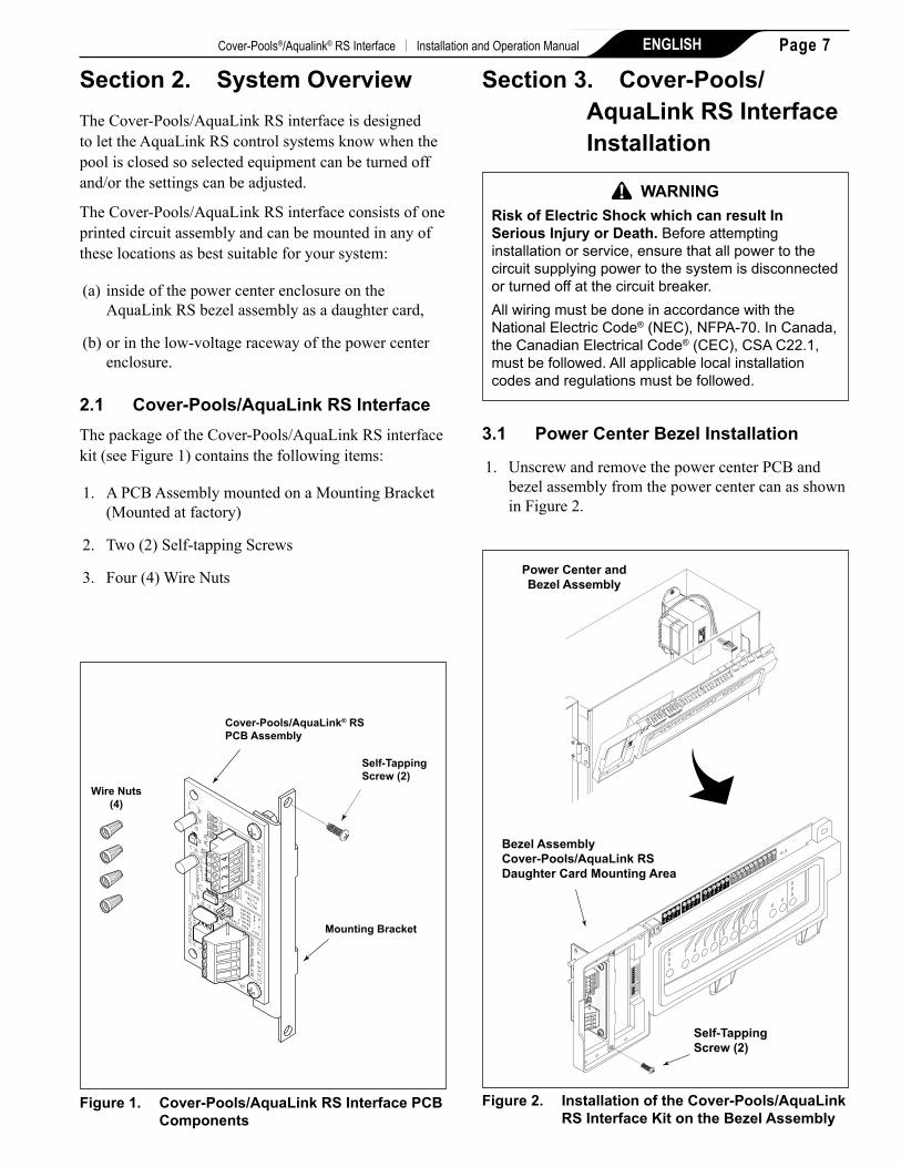
Section 2. System OverviewThe Cover-Pools/AquaLink RS interface is designed to let the AquaLink RS control systems know when the pool is closed so selected equipment can be turned off and/or the settings can be adjusted.
The Cover-Pools/AquaLink RS interface consists of one printed circuit assembly and can be mounted in any of these locations as best suitable for your system:
(a) inside of the power center enclosure on the AquaLink RS bezel assembly as a daughter card,
(b) or in the low-voltage raceway of the power center enclosure.
2.1 Cover-Pools/AquaLink RS InterfaceThe package of the Cover-Pools/AquaLink RS interface kit (see Figure 1) contains the following items:
1. A PCB Assembly mounted on a Mounting Bracket (Mounted at factory)
2. Two (2) Self-tapping Screws
3. Four (4) Wire Nuts
Figure 1. Cover-Pools/AquaLink RS Interface PCB Components
Self-TappingScrew (2)
Mounting Bracket
Cover-Pools/AquaLink® RSPCB Assembly
Wire Nuts(4)
Section 3. Cover-Pools/AquaLink RS Interface Installation
WARNINGRisk of Electric Shock which can result In Serious Injury or death. Beforeattemptinginstallationorservice,ensurethatallpowertothecircuitsupplyingpowertothesystemisdisconnectedorturnedoffatthecircuitbreaker.AllwiringmustbedoneinaccordancewiththeNationalElectricCode®(NEC),NFPA-70.InCanada,theCanadianElectricalCode®(CEC),CSAC22.1,mustbefollowed.Allapplicablelocalinstallationcodesandregulationsmustbefollowed.
3.1 Power Center Bezel Installation
1. Unscrew and remove the power center PCB and bezel assembly from the power center can as shown in Figure 2.
Figure 2. Installation of the Cover-Pools/AquaLink RS Interface Kit on the Bezel Assembly
Bezel Assembly Cover-Pools/AquaLink RS Daughter Card Mounting Area
Power Center andBezel Assembly
Self-TappingScrew (2)
4 3 2 1
4 3 2 1
6 5 4 3 2 110 9 8 7 6 5 4 3 2 1
Page 7 ENGLISH Cover-Pools®/Aqualink® RS Interface | Installation and Operation Manual
High Voltage
Low
Vol
tage
Rac
eway
Filter Pump Relay Aux. 3 Relay
S1
S2
RESET
SERVICE
TIME OUT
FILTER PUMP
AUX 1AUX 2
AUX 3AUX 4
AUX 5AUX 6
AUX 7
RS6 & RS8 ONLY RS8 ONLY
HEATER SOLAR
POOL MODE
SPA MODE
SPA DRAIN
SPA FILL
AUTO
6 5 4 3 2 1 10 9 8 7 6 5 4 3 2 14 3 2 1 4 3 2 1
Self-TappingScrew (2)
Figure 3. Installation of the Cover-Pools/AquaLink RS board in the Low-Voltage Raceway
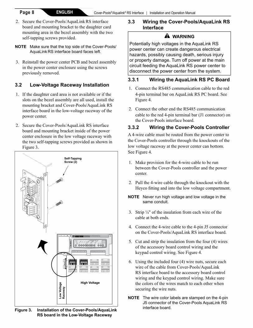
2. Secure the Cover-Pools/AquaLink RS interface board and mounting bracket to the daughter card mounting area in the bezel assembly with the two self-tapping screws provided.
NOTE MakesurethatthetopsideoftheCover-Pools/AquaLinkRSinterfaceboardfacesleft.
3. Reinstall the power center PCB and bezel assembly in the power center enclosure using the screws previously removed.
3.2 Low-Voltage Raceway Installation
1. If the daughter card area is not available or if the slots on the bezel assembly are all used, install the mounting bracket and Cover-Pools/AquaLink RS interface board in the low-voltage raceway of the power center.
2. Secure the Cover-Pools/AquaLink RS interface board and mounting bracket inside of the power center enclosure in the low voltage raceway with the two self-tapping screws provided as shown in Figure 3.
3.3 Wiring the Cover-Pools/AquaLink RS Interface
WARNINGPotentiallyhighvoltagesintheAquaLinkRSpowercentercancreatedangerouselectricalhazards,possiblycausingdeath,seriousinjuryorpropertydamage.TurnoffpoweratthemaincircuitfeedingtheAquaLinkRSpowercentertodisconnectthepowercenterfromthesystem.
3.3.1 Wiring the AquaLink RS PC Board1. Connect the RS485 communication cable to the red
4-pin terminal bar on AquaLink RS PC board. See Figure 4.
2. Connect the other end the RS485 communication cable to the red 4-pin terminal bar (J1 connector) on the Cover-Pools interface board.
3.3.2 Wiring the Cover-Pools ControllerA 4-wire cable must be routed from the power center to the Cover-Pools controller through the knockouts of the low voltage raceway at the power center can bottom. See Figure 4.
1. Make provision for the 4-wire cable to be run between the Cover-Pools controller and the power center.
2. Pull the 4-wire cable through the knockout with the Heyco fitting and into the low voltage compartment.
NOTE Neverrunhighvoltageandlowvoltageinthesameconduit.
3. Strip ¼" of the insulation from each wire of the cable at both ends.
4. Connect the 4-wire cable to the 4-pin J5 connector on the Cover-Pools/AquaLink RS interface board.
5. Cut and strip the insulation from the four (4) wires of the accessory board control wiring and the keypad control wiring. See Figure 4.
6. Using the included four (4) wire nuts, secure each wire of the cable from Cover-Pools/AquaLink RS interface board to the accessory board control wiring and the keypad control wiring. Make sure the colors of the wires match to each other when securing the wire nuts.
NOTE Thewirecolorlabelsarestampedonthe4-pinJ5connectoroftheCover-PoolsAquaLinkRSinterfaceboard.
Page 8 ENGLISH Cover-Pools®/Aqualink® RS Interface | Installation and Operation Manual

Figure 4. Wiring the Cover-Pools/AquaLink RS Interface Board
High Voltage
Filter Pump Relay Aux. 3 Relay
S1
S2
RESET
SERVICE
TIME OUT
FILTER PUMP
AUX 1AUX 2
AUX 3AUX 4
AUX 5AUX 6
AUX 7
RS6 & RS8 ONLY RS8 ONLY
HEATER SOLAR
POOL MODE
SPA MODE
SPA DRAIN
SPA FILL
AUTO
6 5 4 3 2 1 10 9 8 7 6 5 4 3 2 14 3 2 1 4 3 2 1
AquaLink RS Power Center
Two RelaysAccessory
Board(Optional)
Close Sensor
CoverLinkKeypad
Cover-PoolsAuto-Shutoff
Controller
Low VoltageRaceway Knockouts
1 2 347 8 9
5 6
* 0 #
Open Sensor
MotorOutput Lines
Motor
Pool CoverInput Power120Vac
SensorInput lines Cover-Pools
Control Lines
Accessory BoardControl Lines
Cover-Pools Section
BLK BRN PUR RED
J5 Connector,To Cover-Pools
J1 Connector,To AquaLink PC Board
BRNPURRED
BLK
Page 9 ENGLISH Cover-Pools®/Aqualink® RS Interface | Installation and Operation Manual

4.1.1 disable devicesOn the COVER-POOLS screen, highlight DISABLE DEVICES and press SELECT.
On DISABLE DEVICES screen, use the UP/DOWN arrow keys to highlight the device and press SELECT to disable.
MENU
HELPPROGRAMSET TEMPSET TIMEDISPLAY LIGHTLOCKOUTSPROGRAM GROUPSYSTEM SETUP
JANDY AquaLink RS
FILTER PUMP OFFAIR 79°
06/02/03 MON6:00 PM
EQUIPMENT ON/OFF
MENU / HELPONETOUCH ON/OFF
Section 4. Cover-Pools/AquaLink RS Interface OneTouchTM Set up
The Cover-Pools/AquaLink RS interface will operate with any AquaLink RS control panel, including the iAquaLink, but can only be set up from the OneTouch control panel.
4.1 Cover-Pools/AquaLink RS Interface Set up
On the HOME screen, use the UP/DOWN arrow keys to highlight MENU/HELP and press SELECT.
On the MENU screen, use the UP/DOWN arrow keys to highlight SYSTEM SETUP and press SELECT.
DISABLE DEVICESCOVER CLOSED
AUX1AUX2AUX3AUX4AUX5AUX6AUX7
COVER-POOLSSETUP WHEN COVER
IS CLOSED
AquaPure ADJUSTDISABLE DEVICES
Use ARROW KEYSto set value.Then SELECT.
X
4.1.2 AquaPure® AdjustOn the COVER-POOLS screen, highlight AQUAPURE ADJUST and press SELECT to display the AQUAPURE ADJUST screen.
AQUAPURE ADJUSTCOVER CLOSED
COVER-POOLSSETUP WHEN COVER
IS CLOSED
DISABLE DEVICES
Use ARROW KEYSto set value.Then SELECT.
SET SPA TO: 5%SET POOL TO: 5%
Highlight an itemand press SELECT.
AQUAPURE ADJUST
On the SYSTEM SETUP screen, use the PAGE UP and PAGE DOWN buttons to highlight COVER-POOLS.
Press SELECT to display the COVER-POOLS screen.
COVER-POOLSSETUP WHEN COVER
IS CLOSED
AquaPure ADJUST
SYSTEM SETUP
COVER-POOLS
LABEL AUXFREEZE PROTECTAIR TEMPDEGREES C/FTEMP CALIBRATEIN FLOOR CLEANSOLAR PRIORITY
MORE
DISABLE DEVICES
Use ARROW KEYSto set value.Then SELECT.
PAGEDOWN
PAGEUP
To change the SET POOL or SET SPA percentage on the AQUAPURE ADJUST screen, highlight either SET POOL or SET SPA and press SELECT.
An underscore line will blink under the percentage value, use the UP/DOWN arrow keys to change this value and press SELECT.
AQUAPURE ADJUSTCOVER CLOSED
SET SPA TO: 5%SET POOL TO: 5%
Highlight an itemand press SELECT.
Use ARROW KEYSto set value.Then SELECT.
SET SPA TO: 5%
DISABLE DEVICESCOVER CLOSED
SET POOL TO: 10%
Page 10 ENGLISH Cover-Pools®/Aqualink® RS Interface | Installation and Operation Manual

NOTE
Page 11 ENGLISH Cover-Pools®/Aqualink® RS Interface | Installation and Operation Manual

Zodiac Pool Systems, Inc. 2620 Commerce Way, Vista, CA 92081 1.800.822.7933 | www.ZodiacPoolSystems.com
ZODIAC® is a registered trademark of Zodiac International, S.A.S.U., used under license.All trademarks referenced herein are the property of their respective owners.
©2012 Zodiac Pool Systems, Inc. H0370100 Rev A 1203