aqd40, aqad40, md40, tmd40, tamd40 - turbo 36 · pdf fileaqd40, aqad40, md40, tmd40, tamd40...
TRANSCRIPT

Engine
AQD40, AQAD40,MD40, TMD40, TAMD40
Workshop Manual
2(0)
B

1
Workshop Manual
Contens
EngineAQD40, AQAD40, MD40, TMD40, TAMD40
Safety precautions ............................................... 2General information ............................................. 5Repair instructions .............................................. 6
Component guide ................................................... 8
DismantlingCylinder head ......................................................... 9Fuel pipe, electrical equipment ............................ 11Circulation pump .................................................. 11Auxiliary drive gears ............................................ 12Camshaft .............................................................. 12Pistons, connecting rods ..................................... 12Flywheel ............................................................... 13Crankshaft ............................................................ 13
OverhaulDisassembling the cylinder head ......................... 14Cleaning, inspection ............................................. 14Valve guides ......................................................... 15Valves .................................................................. 15Valve seats .......................................................... 15Valve springs ....................................................... 16Rocker arm mechanism ....................................... 16Injectors ............................................................... 16Assembling the cylinder head .............................. 16Cleaning and inspecting the cylinder block .......... 17Pistons, cylinder liners ........................................ 17Connecting rods ................................................... 18Crankshaft ............................................................ 18Camshaft .............................................................. 18Oil pump ............................................................... 18Sea-water pump ................................................... 19
Circulation pump .................................................. 20Heat exchanger .................................................... 21Oil cooler .............................................................. 22
Turbo-CompressorChecking the supercharging pressure ................. 23Measures to be carried out when thesupercharging pressure is too low ....................... 24Cleaning ............................................................... 24Disassembling ...................................................... 25Measuring, inspection .......................................... 26Assembling .......................................................... 27Fitting the turbo-compressor ................................ 28
AssemblingCrankshaft ............................................................ 29Pistons, liners ...................................................... 29Oil pump ............................................................... 31Flywheel ............................................................... 31Auxiliary drive gears ............................................ 31Circulation pump .................................................. 33Oil cooler .............................................................. 34Cylinder Head ...................................................... 34Adjustment of valve clearance ............................. 34Adjustment of injection angle ............................... 35Exterior details ..................................................... 35Venting the fuel system ....................................... 37Adjusting the speed .............................................. 38
Wiring diagram ................................................... 39Fault Finding Table ............................................ 44Special Tools ...................................................... 44Technical Data .................................................... 47

2
Safety Precautions
Check that the warning or information decals onthe product are always clearly visible. Replacedecals that have been damaged or painted over.
Engine with turbocharger: Never start the enginewithout installing the air cleaner (ACL). The ro-tating compressor in the Turbo can cause seri-ous personal injury. Foreign objects entering theintake ducts can also cause mechanical dam-age.
Never use start spray or similar to start the en-gine. The starter element may cause an explo-sion in the inlet manifold. Danger of personal in-jury.
Avoid opening the filler cap for engine coolantsystem (freshwater cooled engines) when theengine is still hot. Steam or hot coolant canspray out. Open the coolant filler cap carefullyand slowly to release pressure before removingthe cap completely. Take great care if a cock,plug or engine coolant line must be removedfrom a hot engine. It is difficult to anticipate inwhich direction steam or hot coolant can sprayout.
Hot oil can cause burns. Avoid skin contact withhot oil. Ensure that the lubrication system is notunder pressure before commencing work on it.Never start or operate the engine with the oil fill-er cap removed, otherwise oil could be ejected.
Stop the engine and close the sea cock beforecarrying out operations on the engine coolingsystem.
Only start the engine in a well-ventilated area. Ifoperating the engine in an enclosed space, en-sure that exhaust gases and crankcase ventila-tion emissions are ventilated out of the workingarea.
IntroductionThis Workshop Manual contains technical data,descriptions and repair instructions for Volvo Pentaproducts or product versions contained in the con-tents list. Ensure that the correct workshop literatureis being used.
Read the safety information and the WorkshopManual “General Information” and “Repair Instruc-tions” carefully before starting work.
ImportantIn this book and on the engine you will find the follow-ing special warning symbols.
WARNING! If these instructions are not fol-lowed there is a danger of personal injury, ex-tensive damage to the product or serious me-chanical malfunction.
IMPORTANT! Used to draw your attention tosomething that can cause damage, productmalfunction or damage to property.
NOTE! Used to draw your attention to important in-formation that will facilitate work or operations.
Below is a summary of the risks and safety precau-tions you should always observe or carry out whenoperating or servicing the engine.
Immobilize the engine by turning off the powersupply to the engine at the main switch (switch-es) and lock it (them) in the OFF position beforestarting work. Set up a warning notice at the en-gine control point or helm.
Generally, all servicing should be carried outwith the engine switched off. Some work (carry-ing out certain adjustments for example) re-quires the engine to be running. Approaching arunning engine is dangerous. Loose clothing orlong hair can fasten in rotating parts and causeserious personal injury.If working in proximity to a running engine, care-less movements or a dropped tool can result inpersonal injury. Avoid burns. Take precautionsto avoid hot surfaces (exhausts, turbochargers,charge air pipes and starter elements etc.) andliquids in supply lines and hoses when the en-gine is running or has been turned off immedi-ately prior to starting work on it. Reinstall allprotective parts removed during service opera-tions before starting the engine.

3
Always use protective goggles where there isa danger of pieces of metal, sparks from grind-ing, acid or other chemicals being thrown intoyour eyes. Your eyes are very sensitive, injurycan lead to loss of sight!
Avoid skin contact with oil. Long-term or re-peated contact with oil can remove the naturaloils from your skin. The result can be irritation,dry skin, eczema and other skin problems.Used oil is more dangerous to health than newoil. Use protective gloves and avoid using oil-soaked clothes and rags. Wash regularly, es-pecially before meals. Use the correct barriercream to prevent dry skin and to make clean-ing your skin easier.
Most chemicals used in products (engine andtransmission oils, glycol, petrol and diesel oil)and workshop chemicals (solvents and paints)are hazardous to health Read the instructionson the product packaging carefully! Always fol-low safety instructions (using breathing appa-ratus, protective goggles and gloves for ex-ample). Ensure that other personnel are notunwittingly exposed to hazardous substances(by breathing them in for example). Ensurethat ventilation is good. Handle used andexcess chemicals according to instructions.
Be extremely careful when tracing leaks in thefuel system and testing fuel injection nozzles.Use protective goggles! The jet ejected from afuel injection nozzle is under very high pres-sure, it can penetrate body tissue and causeserious injury There is a danger of blood poi-soning.
All fuels and many chemicals are inflammable.Ensure that a naked flame or sparks cannot ig-nite fuel or chemicals. Combined with air incertain ratios, petrol, some solvents and hy-drogen from batteries are easily inflammableand explosive. Smoking is prohibited! Ensurethat ventilation is good and that the necessarysafety precautions have been taken beforecarrying out welding or grinding work. Alwayshave a fire extinguisher to hand in the work-place.
Store oil and fuel-soaked rags and fuel and oilfilters safely. In certain conditions oil-soakedrags can spontaneously ignite. Used fuel andoil filters are environmentally dangerous wasteand must be deposited at an approved site fordestruction together with used lubricating oil,contaminated fuel, paint remnants, solvent, de-greasing agents and waste from washingparts.
Never allow a naked flame or electric sparksnear the batteries. Never smoke in proximity tothe batteries. The batteries give off hydrogengas during charging which when mixed with aircan form an explosive gas – oxyhydrogen.This gas is easily ignited and highly volatile.Incorrect connection of the battery can causea spark which is sufficient to cause an explo-sion with resulting damage. Do not disturb bat-tery connections when starting the engine(spark risk) and do not lean over batteries.
Never mix up the positive and negative batteryterminals when installing. Incorrect installationcan result in serious damage to electricalequipment. Refer to wiring diagrams.
Always use protective goggles when chargingand handling batteries. The battery electrolytecontains extremely corrosive sulfuric acid. Ifthis comes into contact with the skin, wash im-mediately with soap and plenty of water. If bat-tery acid comes into contact with the eyes, im-mediately flush with copious amounts of waterand obtain medical assistance.
Turn off the engine and turn off power at mainswitch(es) before carrying out work on theelectrical system.
Clutch adjustments must be carried out withthe engine turned off.
4
Use the lifting eyes mounted on the engine/re-verse gear when lifting the drive unit.Always check that lifting equipment is in goodcondition and has sufficient load capacity to liftthe engine (engine weight including reversegear and any extra equipment installed).
To ensure safe handling and to avoid damagingengine components on top of the engine, use alifting beam to raise the engine. All chains andcables should run parallel to each other and asperpendicular as possible in relation to the topof the engine.
If extra equipment is installed on the engine al-tering its center of gravity, a special lifting de-vice is required to achieve the correct balancefor safe handling.
Never carry out work on an engine suspendedon a hoist.
Never remove heavy components alone, evenwhere secure lifting equipment such as se-cured blocks are being used. Even where lift-ing equipment is being used it is best to carryout the work with two people; one to operatethe lifting equipment and the other to ensurethat components are not trapped and damagedwhen being lifted.When working on-board ensure that there issufficient space to remove components withoutdanger of injury or damage.
Components in the electrical system, ignitionsystem (gasoline engines) and fuel system onVolvo Penta products are designed and con-structed to minimize the risk of fire and explo-sion. The engine must not be run in areaswhere there are explosive materials.
Always use fuels recommended by Volvo Pen-ta. Refer to the Instruction Book. The use oflower quality fuels can damage the engine. Ona diesel engine poor quality fuel can cause thecontrol rod to seize and the engine to overrevwith the resulting risk of damage to the engineand personal injury. Poor fuel quality can alsolead to higher maintenance costs.

5
General information
About the workshop manualThis workshop manual contains technical specifica-tion, descriptions and instructions for repairing thestandard versions of the following engines AQD40,AQAD40, MD40, TMD40, TAMD40. The productdesignation and number should be given in allcorrespondence about the product.
This Workshop Manual has been developed primarilyfor Volvo Penta service workshops and qualifiedpersonnel. Persons using this book are assumed tohave a grounding in marine drive systems and beable to carry out related mechanical and electricalwork.
Volvo Penta is continuously developing their prod-ucts. We therefore reserve the right to makechanges. All the information contained in this book isbased on product data available at the time of goingto print. Any essential changes or modificationsintroduced into production or updated or revisedservice methods introduced after the date of publi-cation will be provided in the form of Service Bulle-tins.
Replacement partsReplacement parts for electrical and fuel systemsare subject to statutory requirements (US CoastGuard Safety Regulations for example). Volvo PentaGenuine parts meet these requirements. Any type ofdamage which results from the use of non-originalVolvo Penta replacement parts for the product willnot be covered under any warranty provided byVolvo Penta.

6
Repair instructions
The working methods described in the ServiceManual apply to work carried out in a workshop. Theengine has been removed from the boat and isinstalled in an engine fixture. Unless otherwisestated reconditioning work which can be carried outwith the engine in place follows the same workingmethod.
Warning symbols occurring in the Workshop Manual(for their meaning see Safety information)
WARNING!
IMPORTANT!
NOTE!
are not in any way comprehensive since it is impos-sible to predict every circumstance under whichservice work or repairs may be carried out. For thisreason we can only highlight the risks that can arisewhen work is carried out incorrectly in a well-equipped workshop using working methods and toolsdeveloped by us.
All procedures for which there are Volvo Pentaspecial tools in this Workshop Manual are carriedout using these. Special tools are developed torationalize working methods and make proceduresas safe as possible. It is therefore the responsibilityof any person using tools or working methods otherthan the ones recommended by us to ensure thatthere is no danger of injury, damage or malfunctionresulting from these.
In some cases there may be special safety precau-tions and instructions for the use of tools and chemi-cals contained in this Workshop Manual. Thesespecial instructions should always be followed ifthere are no separate instructions in the WorkshopManual.
Certain elementary precautions and common sensecan prevent most risks arising. A clean workplaceand engine eliminates much of the danger of injuryand malfunction.
It is of the greatest importance that no dirt or foreignparticles get into the fuel system, lubrication sys-tem, intake system, turbocharger, bearings andseals when they are being worked on. The result canbe malfunction or a shorter operational life.
Our joint responsibilityEach engine consists of many connected systemsand components. If a component deviates from itstechnical specification the environmental impact of anotherwise good engine may be increased significantly.It is therefore vital that wear tolerances are main-tained, that systems that can be adjusted are adjustedproperly and that Volvo Penta Genuine Parts as used.The engine Maintenance Schedule must be followed.
Some systems, such as the components in the fuelsystem, require special expertise and special testingequipment for service and maintenance. Some com-ponents are sealed at the factory for environmentalreasons. No work should be carried out on sealedcomponents except by authorized personnel.
Bear in mind that most chemicals used on boats areharmful to the environment if used incorrectly. VolvoPenta recommends the use of biodegradable degrea-sing agents for cleaning engine components, unlessotherwise stated in a workshop manual. Take specialcare when working on-board, that oil and waste istaken for destruction and is not accidentally pumpedinto the environment with bilge water.
Tightening torquesTightening torques for vital joints that must be tight-ened with a torque wrench are listed in workshopmanual “Technical Data”: “Tightening Torques” and arecontained in work descriptions in this Manual. Alltorques apply for cleaned threads, screw heads andmating surfaces. Torques apply for lightly oiled or drythreads. If lubricants, locking fluid or sealing com-pound are required for a screwed joint this informationwill be contained in the work description and in “Tight-ening Torques” Where no tightening torque is stated fora joint use the general tightening torques according tothe tables below. The tightening torques stated are aguide and the joint does not have to be tightened usinga torque wrench.
Dimension Tightening TorquesNm lbt.ft
M5 6 4.4M6 10 7.4M8 25 18.4M10 50 36.9M12 80 59.0M14 140 103.3
7
Tightening torques-protractor(angle) tightening
Tightening using both a torquesetting and a protractor angle re-quires that first the recommendedtorque is applied using a torquewrench and then the recommendedangle is added according to theprotractor scale. Example: a 90°protractor tightening means that thejoint is tightened a further 1/4 turn inone operation after the stated tight-ening torque has been applied.
LocknutsDo not re-use lock nuts that have been removedduring dismantling as they have reduced service lifewhen re-used – use new nuts when assembling orreinstalling. For lock nuts with a plastic insert suchas Nylock® the tightening torque stated in the tableis reduced if the Nylock® nut has the same headheight as a standard hexagonal nut without plasticinsert. Reduce the tightening torque by 25% for boltsize 8 mm or larger. Where Nylock® nuts are higher,or of the same height as a standard hexagonal nut,the tightening torques given in the table apply.
Tolerance classesScrews and nuts are divided into different strengthclasses, the class is indicated by the number on thebolt head. A high number indicates stronger material,for example a bolt marked 10-9 indicates a highertolerance than one marked 8-8. It is therefore impor-tant that bolts removed during the disassembly of abolted joint must be reinstalled in their originalposition when assembling the joint. If a bolt must bereplaced check in the replacement parts catalogueto make sure the correct bolt is used.
SealantsA number of sealants and locking liquids are used onthe engines. The agents have varying properties andare used for different types of jointing strengths,operating temperature ranges, resistance to oil andother chemicals and for the different materials and gapsizes in the engines.
To ensure service work is correctly carried out it isimportant that the correct sealant and locking fluidtype is used on the joint where the agents are re-quired.
In this Volvo Penta Service Manual the user will findthat each section where these agents are applied inproduction states which type was used on the engine.
During service operations use the same agent or analternative from a different manufacturer.
Make sure that mating surfaces are dry and free fromoil, grease, paint and anti-corrosion agent beforeapplying sealant or locking fluid.
Always follow the manufacturer’s instructions for useregarding; temperature range, curing time and anyother instructions for the product.
Tow different basic types of agent are used on theengine and these are:
RTV agent (Room temperature vulcanizing). Use forgaskets, sealing gasket joints or coating gaskets. RTVagent is clearly visible when a component has beendismantled; old RTV must be removed before the jointis resealed.
The following RTV agents are mentioned in the Ser-vice Manual: Loctite® 574, Volvo Penta 840879-1,Permatex® No. 3, Volvo Penta P/N 1161099-5,Permatex® No. 77. Old sealant can be removed usingmethylated spirits in all cases.
Anaerobic agents. These agents cure in an absence ofair. They are used when two solid parts, for examplecast components, are installed face-to-face without agasket. They are also commonly used to secureplugs, threads in stud bolts, cocks, oil pressureswitches and so on. The cured material is glass-likeand it is therefore colored to make it visible. Curedanaerobic agents are extremely resistant to solventsand the old agent cannot be removed. When reinstall-ing the part is carefully degreased and then newsealant is applied.
The following anaerobic agents are mentioned in theService Manual: Loctite® 572 (white), Loctite® 241(blue).
NOTE! Loctite® is the registered trademark of Loctite Corpora-tion, Permatex® is the registered trademark of the PermatexCorporation.

8
Component Guide
TMD40
TAMD40
1. Exhaust bend, sea-water cooled2. Turbo-compressor3. Coolant pipe4. Exhaust manifold, fresh-water cooled5. Pipe for oil discharge pump6. Oil dipstick7. Heat exchanger8. Filling, freshwater9. Alternator
10. Draincock, sea-water11. Oil cooler12. Draincock, fresh-water13. Oil filter14. Oil pressure sender15. Oil pressure warner16. Draincock, sea-water17. Draincock, fresh-water18. Sea-water pump19. Sea-water filter20. Engine speed sender21. Injection pump22. Stop solenoid23. Oil filler cap24. Injector25. Glow plug26. Filter for crankcase ventilation27. Positive pressure valve for crankcase
ventilation28. Air cleaner29. Inspection cover, injection timing30. Feed pump31. Fuel filter32. Engine number plate33. Fuel pipe connection for suction and
return pipes

9
Drain off the cooling water and lubricating oil togetherwith any fuel in the fuel filter and injection pump. Cleanthe engine externally.
1. AQD40, TMD40, MD40: Take off the alternator drivebelts. Remove the hose nipple and the ventilation pipefrom the thermostat housing cover.
AQD40A, TMD40A, MD40A
3a. TMD40, MD40: Take off the coolant pipes between theengine and the reversing gear.
AQD40. Take off the pipe between the heat exchangerand the turbo-compressor.
Remove the screws holding the heat exchanger and re-move the heat exchanger by drawing it forward.
AQD40B, TMD40B
AQAD40, TAMD40
3b. Take off the coolant pipes. Remove the screws holdingthe heat exchanger and remove the heat exchanger bydrawing it forward.
4a. Early prod. Remove the plastic cover from the front ofthe engine. Unscrew the plate on which the relays aremounted and remove the cooling water pipe which is lo-cated at the back of the plate.
2. AQAD40, TAMD40: Take off the alternator drive belts.Remove the ventilation pipe from the thermostat housing.
Dismantling

10
4b. Late prod. Remove all the connections of the cable har-ness and remove the electrical distribution box. Alsoremove the water pipe behind the distribution box.
5. Disconnect the cables from the front and back glow plug.Disconnect the fuel leak-off line from the front injector.Disconnect the delivery lines from the injectors.
6. Remove the inlet manifold, the rocker arm casing, therocker arm bearing bracket and the pushrods.
7. AQAD40, TAMD40: Remove the pipe between the turboand the after cooler. Loosen the bracket under the aftercooler and remove the after cooler.
8. Remove the oil pipes between the turbo-compressor andthe engine block, also the coolant pipe between the ex-haust manifold and the engine block.
9. Remove the exhaust manifold together with the turbo-compressor. Pull out the tube for the oil dipstick and theoil discharge pipe. Unscrew the front lifting eye. Take offthe cylinder head.
11
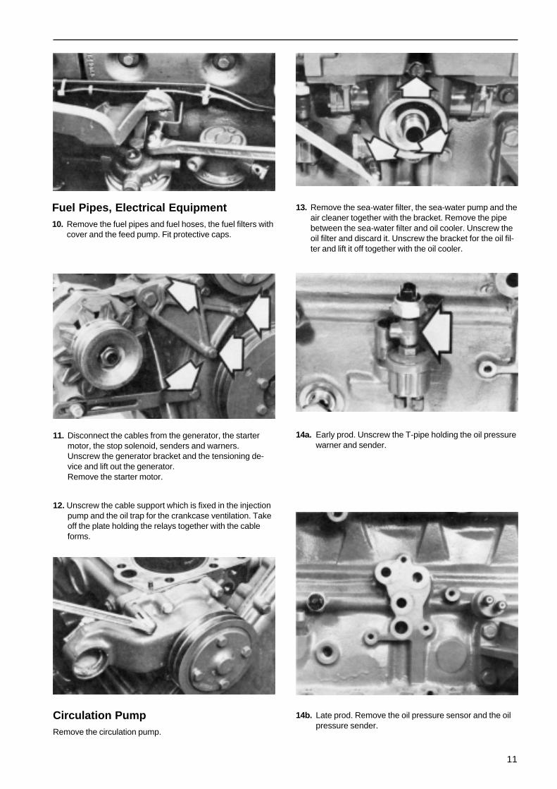
Fuel Pipes, Electrical Equipment10. Remove the fuel pipes and fuel hoses, the fuel filters with
cover and the feed pump. Fit protective caps.
11. Disconnect the cables from the generator, the startermotor, the stop solenoid, senders and warners.Unscrew the generator bracket and the tensioning de-vice and lift out the generator.Remove the starter motor.
12. Unscrew the cable support which is fixed in the injectionpump and the oil trap for the crankcase ventilation. Takeoff the plate holding the relays together with the cableforms.
Circulation PumpRemove the circulation pump.
13. Remove the sea-water filter, the sea-water pump and theair cleaner together with the bracket. Remove the pipebetween the sea-water filter and oil cooler. Unscrew theoil filter and discard it. Unscrew the bracket for the oil fil-ter and lift it off together with the oil cooler.
14a. Early prod. Unscrew the T-pipe holding the oil pressurewarner and sender.
14b. Late prod. Remove the oil pressure sensor and the oilpressure sender.

12
Auxiliary Drive Gears15. Remove the belt pulley which is fitted on the crankshaft
polygon hub. Release the polygon hub centre bolt andpull the hub off using puller 884533.
16. Remove the cover over the auxiliary drive gear casing.Release the 4 bolts in the injection pump lifter. Removethe sea-water pump driver and the injection pump drivegear.
17. Release the 3 bolts fastening the injection pump and liftthe pump off. Release the centre bolt and pull off thecamshaft drive gear with puller 2679.
18. Remove the idler gear and its bearing journal after loos-ening the 3 attaching bolts. Remove the crankshaft gearwith puller 2658.
Camshaft19. Remove the inspection covers and take out the valve
tappets. Release the camshaft thrust washer and lift thecamshaft out.
Pistons, Connecting Rods20. Remove the sump, the oil pump with pipe and bracket.
Remove the reinforcement plate, if fitted. Remove thepistons and connecting rods.
NOTE! Be careful not to damage the piston cooling noz-zles.

13
21. Extract the cylinder liners with the aid of a cylinder linerpuller.
Flywheel22. Remove the auxiliary drive gear casing, the connecting
ring (for reversing gear or AQ-gear), the driving disc andthe flywheel casing.
Crankshaft23. Remove the crankshaft, noting that the main bearing
caps are numbered. Remove the piston cooling nozzles.

14
Overhaul
Cylinder Head
1. DisassemblingA. Remove the electric wiring plate and the glow plugs. Re-
move the injectors and fit protective caps to the tips ofthe injector nozzles.
B. Remove the valve springs and valves with the aid of avalve spring clamp. Place the valves in order in a valvestand. Remove and discard the rubber seals for the inletvalves.
2. Cleaning and InspectionClean all the parts. Pay particular attention to the oil andcoolant channels. Check for leakages by pressure testing.Check the plane of the cylinder head with a steel rule.Should the cylinder head be out of plane in excess of 0,10mm within a measuring length of 100 mm or 0,20 mm withinthe total length of the cylinder head, the cylinder head mustbe ground to plane.
Grinding Flat(Early prod. engines with removable inserts).
Remove the inserts from the chambers and turn down thelower ends (surface nearest the piston) by the same amountas the cylinder head is ground down. After being grounddown flat, the height of the cylinder head must not be lessthan 86.7 (3.41339 in). Check that the inserts are flush withrespect to the surface of the cylinder head within ±0.05 mm(0.00197 in). Check the dimension A, see point 5.
3. Cylinder Head – Pressure TestingA. Plug all coolant holes with sealing washers part-no 6531.
Use bolt part-no 955353 and nut part-no 955784 19 pcsof each, to tighten the sealing washers.
B. Attach the connection washer part-no 6532 to the end ofthe cylinder head and connect the pressure testing de-vice part-no 6662. Use the gasket of the water pipe plus4 bolts part-no 955295 for the connection washer.
C. Tighten the reduction valve until the pressure gauge indi-cates 100 kPa (1 kp/cm2).
D. Lower the cylinder head in water to facilitate the findingof possible leakages.
E. After the pressure testing, the cylinder head should bedried with compressed air.
4. Valve GuidesA. Check the valve guides for wear by inserting a new
valve. Measure the clearance with the aid of a dialgauge. Change the guides if necessary.
Wear LimitsInlet valve, max. clearance .................... 0.15 mm 0.00951 inExhaust valve, max. clearance .............. 0.17 mm 0.00669 in

15
A = 18 mm (0.70866 in)
B. Press out the valve guides using drift 2818. Oil the newguides externally and press them into position with tool5028. The tool should be pressed right down against thecylinder head. Ream the guides if necessary.
5. ValvesGrind the valves on the valve grinding machine. The angle(D) should be 29.5° for the inlet valve and 44.5° for the ex-haust valve. If the thickness of the edge of the disc aftergrinding is less than 1.5 mm (0.05906 in) for an inlet valve or1.3 mm (0.05118 in) for an exhaust valve, the valve shouldbe rejected. Valves with bent stems should also be rejected.If necessary, grind the surface on which the rocker armbears.
A (New valve)in: min. 1.1 mm (0.04331 in)
max. 1.8 mm (0.07087 in)out: min. 0.85 mm (0.03346 in)
max. 1.55 mm (0.06092 in)
B in: 1.38–2.8 mm (0.0543–0.11024 in)out: 1.3–2.6 mm (0.05118–0.10236 in).
C in: 30°, out 45°
D in: 29.5°, out 44.5°
6. Valve SeatsMill or ream the valve seats. The angle (C) should be 30° forthe inlet and 45° for the exhaust. (Check the valve guidesbefore machining the seats, and replace them if necessary).The width of the sealing surface should be 1.3–2.8 mm(0.05118–0.11024 in) for the inlet and 1.3–2.6 mm (0.05118–0.10236 in) for the exhaust. Replace the valve seats whenthe dimension (A), measured with a new valve, exceeds 1.8mm (0.07087) for the inlet or 1.55 mm (0.06102 in) for the ex-haust. A new seat should be ground down so that the dimen-sion (A) is min. 1.1 mm (0.04331 in) for the inlet or 0.85 mm(0.03346 in) for the exhaust.
Replacing Valve SeatsA. Remove the old seat by grinding two notches as shown
in the diagram. Crack the seat with a chisel.
B. Machine the seat recess to the correct dimension, see”Technical Data”. Cool the new seat down in CO2 snowto about 140°F (60°C), and warm up the cylinder headby rinsing it with hot water. Press the seat in with a drift.Machine the seat so that the height, angle and width arecorrect.

16
7. Valve SpringsCheck the valve spring lengths, both unloaded and loaded.
Length without load ................................... 46 mm 1.81102 inLength with load
267–312 N (27.2–31.8 kp) .......................40 mm 1.5748 inLength with load
766–851 N (78.2–86.8 kp) ..................... 30 mm 1.18110 in
8. Rocker Arm MechanismDismantle the rocker arm mechanism and clear the parts.Check the shaft & the bushes for wear. If the bushes need tobe changed, the tool 1867 is used for pressing out and in.(Ensure that the oil hole in the bush coincides with the hole inthe rocker arm). After having been pressed in, the bushesshould be reamed to give an accurate running fit.
Check whether the rocker arm surface which bears on thevalve is worn concave. Minor adjustments can be made withthe valve griping machine. Oil the shaft and fit the parts.
9. InjectorsWhen an injector is tested, the fuel should come out as aproperly directed mist, see the illustration. The opening pres-sure is adjusted by unscrewing the injector and taking itapart, when the adjusting washer (1) can be replaced by awasher of suitable thickness.
10. Assembling the Cylinder HeadClean the cylinder head. Oil the valve stems and fit thevalves, not forgetting the sealing rings for the inlet valves. Fitthe glow plugs and the plate for the electrical wiring. Fit theinjectors together with new steel and copper washers. Donot tighten the injectors.

17
Cylinder Block
11. Cleaning, InspectionRemove all core plugs and clean the cylinder block thor-oughly. Check that all channels are free from deposits andthat there are no cracks in the block. Refit the core plugs us-ing a sealing compound.
12. Pistons, cylinder linersThe pistons and liners are classified and marked with a let-ter. A piston which is marked with a D must thus only be fit-ted into a liner with the same letter. Check the pistons andliners for damage before making any measurements.
Class Cylinder diameter
C 92.00–92.013.54331–3.54370 in
D 92.01–92.023.54370–3.54409 in
E 92.02–92.033.54409–3.54448 in
B. Measure the cylinder liner diameter at a number of pointsround the circumference and at a number of differentheights between the top and bottom dead-centre posi-tions (B and C).
Change the piston and the liner if the wear is as much as0.25–0.30 mm (0.00984–0.01181 in).
Measure the piston diameter (A) at right angles to thegudgeon pin and 15 mm (0.59055 in.) from the bottom ofthe piston. Calculate the maximum and minimum pistonclearance (the max. and min. liner diameter minus thepiston diameter).
Piston clearance (new parts): 0.08–0.12 mm. 0.00315–0.00472 in.
C. Measure the piston ring gap on the new rings. If the lineris not new, the check should be made with the ring in thebottom dead-centre position.
The gap should be:Compression rings: 0.40–0.65 mm 0.01515–0.02559 inScraper rings: 0.25–0.40 mm 0.00984–0.01575 in
D. Measure the clearance of the piston rings in theirgrooves.NOTE! The upper ring should be flush with the surfaceof the piston at the point of measurement, see illustration.
The clearance should be:Upper compression rings:
0.08–0.13 mm 0.00315–0.00512 inLower compression rings:
0.07–0.10 mm 0.00276–0.00394 inScraper rings:
0.04–0.07 mm 0.00157–0.00276 in

18
13. Connecting RodsA. Check the connecting rods for straightness and twist.
B. Check the connecting rod bushings, using the gudgeonpins as gauges. There should be no noticeable play. If itis necessary to replace the bushings, drift 6271 shouldbe used for pressing out and in. Ensure that the oil holein the bushing lines up with that in the connecting rod.
Ream the new bushings. When the fit is correct, an oiledgudgeon pin should slide slowly though the bushing un-der its own weight.
14. CrankshaftMeasure the big-end journals and the main bearing journals.The out-of-round must not exceed 0.04 mm (0.00157 in) andthe taper should not exceed 0.05 mm (0.00197 in). If thesevalues are exceeded, the crankshaft should be ground to asuitable undersize. (See ”Technical Data”).
15. CamshaftCheck the camshaft for wear on the cams and bearing rac-es. Also check the wear on the bearing. The bearings arepressed into their recesses and must be line milled afterpressing in.
Max. allowable wear on races or bearings 0.05 mm (0.00197in).
16. Oil PumpA. Remove the idler. Pull off the drive gear with puller 6273.
Remove the key and the brass washer.

19
B. Unscrew the bolts holding the pump housing. Press thehousing loose by screwing the bolts in from the frontside. Remove the pump gear.
C. Check the housing for scoring and wear. Check the sealbetween the bracket and the pump housing. If leakagehas occurred, the surfaces will be blackened. The bush-ings should be changed if the radial play between theshaft and the bushing is 0.15 mm (0.00591 in) or more.The new bushings should be reamed to give an accuraterunning fit with the housing bolted tightly onto bracket.The idler should be replaced if the radial clearance ex-ceeds 0.20 mm (0.00787 in). Check the pump gear forwear on the tooth flanks, external diameter and end fac-es. Check the end play and the tooth flank clearance.
D. Oil the parts. Fit the pump gear and bolt the housing on. Fitthe brass washer and the key.
Press the drive wheel on so that a 0.05 mm (0.00197 in)feeler gauge fits accurately and evenly between the wheeland the brass washer.
17. Sea-Water PumpA. Remove the cover and prise out the impeller using two
screwdrivers. (Place some kind of protection under thescrewdrivers so that the housing is not damaged). Turnthe pump over and remove the lock ring. Turn the pumpback again and press out the shaft, the bearings and thesealings.
B. Grease the new bearings and press them into the shaftso that they fit right over the thickest part of the shaft.
C. Replace the old cam disc by the new one. (MD40,AQD40, TMD40) Fig. 17E. Grease the sealing rings andpress them into the housing with the lips pointing in op-posite directions; use tool 884347. Place the O-ring be-tween the two sealing rings.
Pass the shaft down into the housing ensuring that theO-ring fits onto the shaft. Press the shaft and the bear-ings into the housing with tool 884347.
(AQAD40, TAMD40), Fig. 17F. Mount the sealings in thehousing. Press the shaft and the bearings into the hous-ing with tool 884347.

20
D. Fit the lock ring, the impeller and the sealing washers. Fitthe cover together with a new gasket.
E. MD40, TMD40, AQD40
F. TAMD40, AQAD40
18. Circulation PumpA. Press the complete shaft including the impeller out of the
pump housing. Loosen the 4 bolts and take off the driver.
Take off the lock ring and prise the belt pulley loose withtwo screwdrivers.
Knock out the inner bearing and the shaft seal with theaid of a small drift.
Clean the housing and the belt pulley. Knock the bearingout of the belt pulley.

21
Heat exchanger
After cooler
B. Pack the bearings with heat-resistant ball-bearinggrease. Fill the space with the bearing with grease.
Press the bearing into the belt pulley. Press the bearinginto the pump housing with the aid of tool 2268 (turn thesealed side of the bearing towards the water).
C. Place the deflector ring on the bearing and press theshaft seal on with tool 2270.NOTE! The carbon ring and the ceramic ring in the sealmust not come into contact with grease or be touchedwith the fingers.
D. Place the ceramic seal ring on the impeller and insert theshaft through the seal. Make sure that the deflector ringis correct. Press the shaft in so that there is a clearanceof 0.8 mm (0.3150 in) between the impeller blades andthe pump housing.
19. Heat Exchanger, AftercoolerAQD40A, TMD40A, MD40A. Remove the cover of the ther-mostat housing. Remove the housing and pull out the heatexchanger insets.
AQAD40, TAMD40: Remove the cover and pull out the in-sert.
Rinse and thoroughly clean the parts. If leakage is suspect-ed, the insert can be pressure tested with i.e. air or kero-sene, pressure: 0,2 MPa (2 kp/cm2). (28.4 lbf/in2).
NOTE! Follow valid safety regulations.
Check that the thermostats open at the correct temperature.Fit the parts in the reverse order, using new O-rings and anew gasket. Grease the insert connections with water resist-ant grease before re-assembling.
22
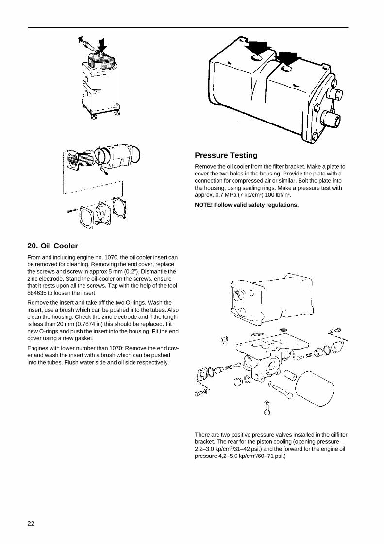
20. Oil CoolerFrom and including engine no. 1070, the oil cooler insert canbe removed for cleaning. Removing the end cover, replacethe screws and screw in approx 5 mm (0.2”). Dismantle thezinc electrode. Stand the oil-cooler on the screws, ensurethat it rests upon all the screws. Tap with the help of the tool884635 to loosen the insert.
Remove the insert and take off the two O-rings. Wash theinsert, use a brush which can be pushed into the tubes. Alsoclean the housing. Check the zinc electrode and if the lengthis less than 20 mm (0.7874 in) this should be replaced. Fitnew O-rings and push the insert into the housing. Fit the endcover using a new gasket.
Engines with lower number than 1070: Remove the end cov-er and wash the insert with a brush which can be pushedinto the tubes. Flush water side and oil side respectively.
Pressure TestingRemove the oil cooler from the filter bracket. Make a plate tocover the two holes in the housing. Provide the plate with aconnection for compressed air or similar. Bolt the plate intothe housing, using sealing rings. Make a pressure test withapprox. 0.7 MPa (7 kp/cm2) 100 lbf/in2.
NOTE! Follow valid safety regulations.
There are two positive pressure valves installed in the oilfilterbracket. The rear for the piston cooling (opening pressure2,2–3,0 kp/cm2/31–42 psi.) and the forward for the engine oilpressure 4,2–5,0 kp/cm2/60–71 psi.)

23
Turbo-CompressorIn the event of excessive exhaust smoke or loss of enginepower, faulty action of the turbo-compressor is to be sus-pected. The supercharging pressure should then bechecked. When speed slowly decreases the bottom of theboat should also be examined and, if necessary, cleaned.
AQD40, TMD40
AQAD40, TAMD40
22. Checking the SuperchargingPressureA. Connect a pressure gauge to the measuring connection
on the intake manifold (see illustration).
Supercharging pressure at differenttemperatures.
A. Supercharging pressure measuredB. Correction curvesC. Temperature of intake air
B. Measure the supercharging pressure under full load andat full throttle whilst the engine speed passes relativelyslowly through a suitable speed, e.g. 56.7 r/s (3.400 r/m)for B-power engines or 46.6 r/s (2.800 r/m) for C-powerengines, see the Supercharging Pressure Diagram un-der ”Technical Data”. The supercharging pressureshould not be less than the specified minimum value.Check the engine speed with a hand tachometer.
NOTE! It is important to maintain full loading long enoughto enable the pressure to stabilise if results are to be cor-rect. Also note that the pressure varies with the tempera-ture of the intake air, as shown in the diagram below.The supercharging pressure is given at +20° (68°F),which implies that the measured pressure must be cor-rected as shown in the diagram if the intake air is not atthis temperature when the measurement is made. Exam-ple: A measured pressure of 80 kPa (0.8 kp/cm2 = 11.3lbf/in2) measured at –10°C (14°F) corresponds to 70 kPa(0.7 kp/cm2 = 9.9 lbf/in2) at +20°C (68°F), i.e. the pres-sure decreases as the temperature rises, due to re-duced air density.

24
23. Measures to be carried out when theSupercharging Pressure is too lowA. Air intake, air cleaner
Check that the air intake is not blocked. Check the air clean-er and replace it if necessary.
B. Leakage
Check for leakage between the turbo housing and bearinghousing or between the compressor housing and the bearinghousing. Also check the joint between the turbo compressorand the inlet manifold.
C. Turbo-compressor
Remove the air cleaner. Check that the compressor rotor isat rest and then see whether the rotor is stiff when turned byhand. If the rotor is difficult to turn, the compressor should bereplaced or reconditioned.
Measure the axial and radial clearances of the rotor unit. Theradial clearance is measured on the turbine side (at the outeredge of the hub, see illustration).
Max. allowable axial clearance: 0.16 mm (0.00630 in).Max. allowable radial clearance: 0.42 mm (0.01654 in).
If the wear limits are reached, the turbo-compressor shouldbe replaced or reconditioned.
If no faults are found:
Check whether the compressor section requires cleaning,see point D. Deposits of soot and oil can cause low super-charging pressure.
D. Cleaning
The compressor section can be cleaned with the unit still onthe engine, as follows:
Remove the compressor housing. Clean the compressorhousing, the compressor rotor and the bearing shield with anagent such as white spirit. Fit the compressor housing andremeasure the supercharging pressure.
If the supercharging pressure is still too low the follow-ing checks should be made:
E. Throttle Control
Check that the throttle control can move the injection pumpthrottle arm to the maximum position.
F. Injection Pump
Check the injection angle and the high idle speed.
If necessary, check the entire pump on a pump test bench.
G. Feed Pressure
If necessary, replace the fuel fine filter and clean thepre-filter. There must be no fuel leakage.
H. Injectors
Check the opening pressure and the spray pattern.
I. Condition of engine
Check the valve clearances and the compression pressure.
If the supercharging pressure is still unsatisfactory, the com-pressor must be reconditioned or replaced.

25
ReconditioningAll moving parts of the turbo compressor are separately bal-anced. This also applies to spare parts. A joint balancing af-ter reconditioning may however be advantageous from theviewpoint of life time length.
24. DisassemblingA. Make line-up marks between the turbine housing (1), the
compressor housing (7) and the bearing housing (3). Re-move the turbine housing and the compressor housing.Clamp the turbine rotor and remove the compressor ro-tor lock nut (8). The position of the wheel should bemarked in relation to the shaft.
B. Remove the compressor rotor. Press the shaft out if therotor is stuck.
C. Remove the bearing end head (5) and press out the pis-ton ring retainer (9). Remove the piston rings, the oil de-flector plate (10), the thrust bearing (11) and the thrustwasher (12). Lift the bearing housing (1) and the heatshield (2) from the shaft. Remove the piston rings (14)and the bushings (13).
Clean the components thoroughly, take care not to dam-age them.

26
25. Measuring, InspectionA. Turbine Rotor with Shaft, Compressor Rotor
Check that the rotors and the shaft are free from me-chanical defects. The blades must not be worn or de-formed. Blades must never be straightened, and anydamaged parts must be replaced by new or recondi-tioned parts.
Place the shaft on two supports located under the bear-ing positions, see illustration. Measure the out-of-truth ofthe shaft at about 20 mm (0.7874 in) from the threadedportion. Max. allowable out-of-truth: 0.007 mm (0.00028in).
Check the diameters at the shaft bearing positions. Min.dia. 9.95 mm (0.39173 in). Check the width of the pistonring grooves in the shaft. The width should be max. 3.0mm (0.11811 in).
B. Bearing housing, Compressor housing,Turbine housing
Check the housing for cracks and other damage. Meas-ure the diameters of the bushing recesses in the bearinghousing. The diameter should be max. 16.064 mm(0.63244 in).
C. Bushings
Check the bearing surfaces for damage. Measure theinternal and external diameters. Internal diameter, max:10.00 mm (0.3937 in). External diameter, min: 15.975mm (0.62895 in). Measure the lengths of the bushings.These should be min: 11 mm (0.43307 in). Note that thebushings should have a push fit in the bearing housing.
D. Piston Rings, Piston Ring Retainers
Measure the width of the piston rings. This should bemin: 1.2 mm (0.04724 in). Measure the width of the pis-ton ring grooves in the piston ring retainer. The widthmust not exceed 3.0 mm (0.11811).
E. Thrust Washer, Thrust Bearing
Measure the thickness of the thrust washer. This shouldbe min. 1.47 mm (0.5787 in). Check the wearing surfac-es of the thrust bearing. The angle, as shown in the illus-tration, should not exceed 30°.
B = Wearing Surfaces

27
26. AssemblingLubricate all moving parts involved in the assem-bly process.
A. Fit the bushing and lock rings on the turbine side of thebearing housing. Also fit the inner lock ring on the com-pressor side.
Fit the heat shield (2) on the bearing housing.
Clamp the hub of the turbine rotor (15) in a vice. Fit thepiston rings (14) and carefully fit the bearing housingover the shaft.
B. Fit the piston ring gaps 90° apart and at 45° with respectto the oil inlet (see illustration). Compress the rings sothat they can be inserted in the bearing housing. Afterthis, check that the heat shield turns easily.
C. Fit the bushing and the external lock ring on the com-pressor side of the bearing housing. Fit the thrust wash-er (12), the thrust bearing (11) and the oil deflector plate(10). Fit the piston rings on the piston ring retainer (9).Arrange the piston ring gaps in the same way as on theturbine side and fit the retainer in the bearing end head(5).
D. Apply Curil T to the sealing surfaces of the bearing endhead and screw the head into the bearing housing.NOTE! The self-locking bolts (4) should be replaced bynew ones. (If the old bolts are used, they should be se-cured with Loctite). Tightening Torque: 8 Nm (0.8 kpm)(5.8 ft/lbs).
Heat the compressor rotor up to about 100°C and fit itinto the shaft. Tighten nut (8), torque 10 Nm (1 kpm)(7.233 ft/lbs). Check the torque after the parts havecooled down.

28
E. Fit the O-ring on the bearing end head and fit the com-pressor housing (7). Torque 7 Nm (0.7 kpm) (5.0 ft/lbs).Fit the turbine housing (1). Tightening torque: 8 Nm (0.8kpm) (5.8 ft/lbs).
27. Fitting the turbo-compressorA. Change the engine oil and the lubricating oil filter. Bear-
ing damage in the turbo-compressor is almost alwayscaused by sludge deposits in the engine lubricating sys-tem. The presence of sludge deposits can be checkedby lifting off the rocker arm casing. If deposits are found,the complete lubrication system must be thoroughlycleaned before a new or reconditioned turbo-compressoris fitted.
The correct grade of oil must be used (see ”TechnicalData”), and oil changes must be carried out in accord-ance with the instruction book in order to keep the en-gine clean.
Also check the delivery and return lines to the turbo-compressor.
B. Clean the intake line between the turbine and the aircleaner. If the compressor rotor has been damaged,pieces may still remain which can damage the new com-pressor rotor.
C. Fit the turbo-compressor on the engine. After this, injectlubricating oil into the compressor bearing system beforefitting the delivery oil line.
D. Turn the engine over, with the stop button pushed in, un-til oil pressure is obtained. Then disconnect the upper oilpipe on the turbo-compressor and check that oil is com-ing out of it.

29
Assembling
Use new gaskets, sealing rings, sealing washers and lockwashers. Apply grease or oil to the sealing rings. (The cylin-der liner sealing rings should be smeared with soap). Also oilthe movable parts before fitting.
1. Fit the cylinder liners into the block without sealing rings.Measure the liner height, dimension A in the illustration.The measurement should be made at four points oneach liner. The height should be: 0.26–0.31 mm(0.01024–0.01220 in), but the difference between two ad-jacent liners should not exceed 0.02 mm (0.00079 in).Mark the liners so that they come in the same position inthe final assembly.
Pistons, Liners2. With effect from engine number 11900 altered cylinder
liners and cylinder block have been introduced in pro-duction. These alterations have been made so that theliner can be installed more easily and also to reduce therisk of damage to the sealing rings.
The new liners can be used on earlier engines but theearlier liners cannot be used on later engines.
1 = Black with violet marking2 = Black3 = Black (this ring and ring groove has been
introduced with engine no 2201)
3. Lift the cylinder liners and fit the sealing rings as shownin the illustration. Smear the sealing rings and the lowerguides in the block with soapy water. Fit the liner into theblock. (Center the liners so that the upper guides enter).
4. Install the cylinder liners, using mandrel part-no 6598and standard shaft part-no 2000.
Early prod. Late prod.
A = 133.0 mm 134.5 mmB = 131.0 mm 141.0 mm

30
5. Fit all piston cooling nozzles.
6. Fit the main bearings and the crankshaft (lubricate bear-ing surfaces with engine oil. Fit the two thrust washers inthe engine block, one on either side of the middle mainbearing. Check the axial clearance. It should be 0.10–0.31 mm (0.00394–0.01220 in).
7. Fit the main bearing caps so that their numbering is cor-rect. (No. 1 at the front). Tightening torque: See ”Techni-cal Data”. Oil the threads.
8. Heat the pistons up to about 100°C (212°F). Fit the pis-tons and connecting rods so that the front markings onthe pistons and the numbers on the connecting rods areas shown in the illustration.
9. Fit the piston rings with the aid of piston pliers. The com-pression rings are marked ”Top”. The oil scraper ringcan be fitted either side up. Fit the big-end bearing shells.
Oil the pistons, the piston rings and the big-end bearings.Arrange the piston rings so that the gaps are about 120°apart.
Fit the pistons so that the front markings point forward.Use assembly tool 5031.
NOTE! If the pistons are pushed down too far, the cool-ing nozzles may be damaged.

31
10. Fit the big-end bearing caps so that their markings agreewith those on the connecting rod. Oil the threads. Tight-ening torque: 113 Nm (11.3 kpm) (81.73 ft/lbs).
Oil Pump11. If the engine has a reinforcement plate (2) the threads of
the bolts must be dipped in anti-rust medium, part no.598177, 24 hours max before assembling. At assemblingthe bolts must be dripfree. Clean the mating surfacescarefully. Tightening torque 46±5 Nm.
Screw the oil pump tight to the front main bearing. Fitnew sealing rings in accordance with the illustration.NOTE! Two yellow sealing rings should be fitted to theend of the delivery pipe which is connected to the block.Screw the bracket for the suction pipe to main bearingNo. 5. Screw tight the oil pipes. The reducing valve (1) isfitted between the suction pipe and the pump.
Flywheel12. Fit a new sealing ring in the flywheel casing (grease the
ring before the casing is fitted). Fit the flywheel casingand the auxiliary drive gear casing.
Fit the flywheel. Tightening torque 105 Nm (10,5 kpm),75,95 ft/lbs. With effect from engine number 31816, 115Nm (11,5 kpm) 82 ft/lbs.
NOTE! The flywheel is provided with a guide-sleeve,which must match the crankshaft. Fit the drivingdisc and the connecting flange. Fit the oil sump.
Auxiliary Drive GearsAll the gearwheels in the auxiliary drive which affect thetiming are marked with punch marks.

32
12a. Oil the camshaft bearings. Fit the camshaft, the dis-tance ring and the thrust washer. Check the axial clear-ance. This should be 0.04–0.12 mm (0.00157–0.00472in).
Clean carefully each valve tappet and apply molybde-num disulphide on the surface against the camshaft. Oilthe holes in the cylinder block. Fit the valve tappets andthe inspection covers.
Earlier prod. R = 4.7 mm Later prod. R = 6 mm
12b. NOTE! Later production of engines have altered valvetappets and push rods. These may not be mixed withearlier production.
13. Check that the key is fitted in the crankshaft. Fit thecrankshaft gear using tool 6404.NOTE! Ensure that the gearwheel meshes with the oilpump gear.
14. Fit the key into the camshaft. Heat the camshaft gear toabout 100°C (212°F) and fit it on the shaft.
Fit the idler gear with its bearing journal so that the mark-ings agree. The angular position of the bearing journal isimmaterial. Tightening torque: Idler gear 23 Nm (2,3 kpm)(16.636 ft/lbs). Secure the bolts with the lock washer,(only early prod.). Tighten the camshaft drive gear. Tight-ening torque: 80 Nm (8 kpm) (5.8 ft/lbs).
15. Remove the cover from the side of the injection pump.Turn the pump so that the line-up marking is visible (A).Later production of engines have a marking on the carri-er (B). Position the carrier marking in a way that it pointsobliquely upwards to the left (the marking then points to-wards number 1 pressure line connection). Fit the pumpon the engine, not forgetting the O-ring on the flange. Donot tighten the nuts.

33
16. Fit the pump gear so that the markings agree.NOTE! Later production of the pump gear wheel car-ries markings for the 6-cylinder engine as well as forthe 4-cylinder one. Screw the pump gear tight togetherwith the driver.NOTE! The bolts are unevenly spaced so that the drivercan only be fitted in one position. Tightening torque: 23Nm (2.3 kpm) (16.636 ft/lbs). Fit the driver for thesea-water pump.
17. Fit a new sealing ring in the auxiliary drive gear casingcover. Saturate the sealing ring with oil and fit the covertogether with a new gasket.
18. Apply molybdenum disulphide to the end of the crank-shaft. Heat the polygon hub up to about 100°C (212°F)and fit it into the shaft. If necessary, the hub can bepressed on with tool 6404. Fit the washer and the centrebolt. Tightening torque: 180 Nm (18 kpm) (130.2 ft/lbs).Fit the belt pulley. Tightening torque: 25 Nm (2.5 kpm)(18.00 ft/lbs).
Circulation Pump19. Fit the circulation pump and the front lifting eye.
20a. Early prod. Fit the T-tube which holds the oil pressurewarner and sender.

34
20b. Later prod. Install the oil pressure sensor and the oilpressure sender.
Oil Cooler21. Fit the oil filter bracket and the oil cooler. Fit a new oil fil-
ter, see the instructions for the filter.
Cylinder Head
22. Place the cylinder head gasket and the cylinder head onthe cylinder block. Moisten the cylinder head bolts withrust protecting medium. Item No. 282036 (or a mixture of75% Tectyl 511 and 25% kerosene). The bolts should befree from drip when fitted.NOTE! The bolts are phosphated and must not becleaned with a wire brush.
Tighten the cylinder head bolts in accordance with thetightening diagram in the following stages: 30, 90 and130 Nm (3, 9, 13 kpm), (21.7, 65.1, 94.0 ft/lbs).NOTE! The cylinder head bolts shall be tightened afterthe engine has been run for approx. 1 h. (warm or coldengine).
23. Fit the push rods and the rocker arm bearing bracket.Tightening torque: 23 Nm (2,3 kpm) (16.636 ft/lbs).
24. Valve AdjustmentA. NOTE! The valve clearance must not be adjusted with
the engine running. Valve clearance for all valves, en-gine hot or cold: 0.40 mm (0.01575 in). Adjust the valveclearance for Cylinder No. 1 with the piston in the firingposition. The valves on Cylinder No. 6 will then ”Rock”.
B. Turn the engine over one third of a revolution on its cor-rect direction of rotation and adjust the clearance on No.5 cylinder. (The valves in cylinder No. 2 will then”Rock”). Adjust the clearances for the other cylinders inthe order of firing.
Order of Firing 1 5 3 6 2 4
Corresponding cylinderwhose valves ”Rock” 6 2 4 1 5 3
A = Inlet B = Outlet

35
26. Adjustment of Injection Angle(The rocker arm casing, pressure pipes and the cover of theflywheel casing should be removed).
A. Turn the engine in the correct direction of rotation untilboth the valves in cylinder No. 6 are ”rocking”. Rotatethe engine backwards (against the direction of rotation)to 30° b.t.d.c.
Remove the center bolt on the rear end of the injectionpump, and fit the tool 884612 and an indicator instrument884151. Set the instrument to zero.
B. Turn the engine in the direction of rotation until the read-ing of the indicators is 1 mm. Then the grading of the fly-wheel will show: MD40 0-1°, TMD40 2-3°, TAMD40 1–2°after TDC. If the injection angle requires altering: Rotatethe engine back to 30° b.t.d.c. Unscrew the pump at-tachment nuts and rotate the pump clockwise (as seenfrom the front), if the injection is too retarded. If the injec-tion is too advanced, rotate the pump anti-clockwise.Tighten the pump and repeat the measurement.
Exterior Details26. Fit the pipe between the oil cooler and the sea-water fil-
ter. Note the spacer sleeve on the left hand fastening.
Later production of engines have a bracket withclamp to hold the pipe.
27. Fit the tube for the oil dipstick and the oil discharge pipe.Fit the exhaust manifold. Fit the turbo-compressor (NotMD40).
28. Fit the coolant pipe between the exhaust manifold andthe cylinder block. Fit the oil pipe between the turbo-compressor and the cylinder block (Not MD40).

36
29. Fit the rocker arm cover, the inlet manifold, the generatorand the starter motor.
30. AQAD40, TAMD40: Fit the aftercooler and the pipe be-tween the turbo and the aftercooler.
31a. Early prod. Fit the cooling water pipe between the cylin-der head and the exhaust manifold (on the engine in thefront.) Screw the pipe fast, also the plate which holdsthe relays. Fit the plastic casing. Screw the cable sup-port fast and connect the cables.
31b. Late prod. Install the coolant pipe between the cylinderhead and the exhaust manifold (at the front end of theengine). Install the electrical distribution box and con-nect the cables.
32. Fit the filter bracket together with a new fuel filter. Fit thefeed pump and all fuel pipes. Tighten the injectors. Tight-ening torque: 23 Nm (2.3 kpm), (16.630 ft/lbs).
AQD40A, TMD40A, MD40A
37
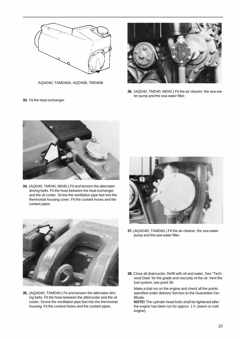
33. Fit the heat exchanger.
34. (AQD40, TMD40, MD40.) Fit and tension the alternatordriving belts. Fit the hose between the heat exchangerand the oil cooler. Screw the ventilation pipe fast into thethermostat housing cover. Fit the coolant hoses and thecoolant pipes.
35. (AQAD40, TAMD40.) Fit and tension the alternator driv-ing belts. Fit the hose between the aftercooler and the oilcooler. Screw the ventilation pipe fast into the thermostathousing. Fit the coolant hoses and the coolant pipes.
36. (AQD40, TMD40, MD40.) Fit the air cleaner, the sea-wa-ter pump and the sea-water filter.
37. (AQAD40, TAMD40.) Fit the air cleaner, the sea-waterpump and the sea-water filter.
38. Close all draincocks. Refill with oil and water. See ”Tech-nical Data” for the grade and viscosity of the oil. Vent thefuel system, see point 39.
Make a trial run on the engine and check all the pointsspecified under delivery Service on the Guarantee Cer-tificate.NOTE! The cylinder head bolts shall be tightened afterthe engine has been run for approx. 1 h. (warm or coldengine).
AQAD40, TAMD40A, AQD40B, TMD40B

38
39. Venting the Fuel SystemNOTE! Be on the lookout for fuel spillage. Exercise specialcare at the venting point.
A. Open the vent screw on the fuel filter by about 4 turns.Pump fuel on with the aid of the hand pump until fuelcomes out free from air bubbles. If the pump does notwork properly, turn the engine over slightly so that thepump driving cam changes position. Close the ventscrew.
B. If the injection pump has been removed, this must also bevented. Pump with the hand pump for about half aminute; this automatically removes any air from the injec-tion pump.
Loosen the delivery pipe nuts on the injectors. Set thegovernor to full revolutions and turn the engine over withthe starter motor until fuel comes out of the deliverypipes. Tighten up the delivery pipe nuts.
40. Adjusting the speedNOTE! The lead seals may only be broken by speciallytrained personnel.
Max unloaded speed
Warm the engine up. Then run the engine light at the maxi-mum speed. Check that the throttle arm (1) pressed upagainst the adjusting screw (3). Check with the pump speedgiven in technical data.
Low Idle
Warm the engine up. Check the speed when the engine isrunning light at the lowest speed. The speed should be 600–700 r/m. If necessary, adjust with adjusting screw (2).
In order to secure the attachment of the front engine sup-ports to the engine block, we recommend that the fourscrews on each support are checked using a torque of 7.3kpm (73 Nm) (54 ft. lb).

39
Wiring Diagram(Early Prod.)
INSTRUMENTPANEL
ENGINE

40
Wiring Diagram(Early Prod.)
Flying bridge
Cable MarkingDesignation Colour mm 2 AWGA’ White 1.5 15A’’ Ivory 1.5 15A’’’ White 2.5 13B Black 1.5 15B’ Black 0.75 18B’’ Black 70 00C Red 6 9C’ Red 70 00C** Red 2.5 13D Grey 1.5 15F Yellow 1.5 15G Brown 1.5 15H’ Blue 2.5 13H’’ Blue 1.5 15H’’’ Blue 4 11I Green/Red 1.5 15I’ Green/Red 0.75 18J Green 1.5 15J’ Green 0.75 18J’’ Green 0.75 18J’’’ Green 6 9K Yellow/Blue 0.75 18K’ Yellow/Blue 1.5 15L Red/White 0.75 18M Blue/Red 0.75 18N White/Red 1.5 15
Instrument Panel1. Key switch2. Stop button3. Rev. counter4. Voltmeter5. Oil pressure gauge6. Temperature gauge7. Protective resistor8. Warning lamp, (glow plugs)9. Instrument lighting
10. Alarm analyser11. Alarm12. Connector
Engine13. Battery14. Main switch15. Starter motor16. Charging regulator17. Alternator18. Oil pressure sender19. Rev. sender20. Temperature sender21. Glow plug22. Connector23. Glow current relay24. Fuse25. Stop solenoid26. Start relay27. Temperature warner (for alarm)28. Oil pressure warner (for alarm)
Flying bridge1. Rev. counter2. Stop button3. Start button4. Warning lamp, charging5. Warning lamp, oil pressure6. Warning lamp, temperature7. Pull switch (spare)8. Instrument lighting9. Connector
10. Electronic signal equipment11. Alarm analyser

41
Instrument Panel1. Voltmeter2. Oil pressure gauge3. Coolant temperature gauge4. Printed circuit card5. Push button
6. Switch for instrument lighting7. Rev. counter8. Key switch9. Alarm
Electrical Wiring Diagram(Late Prod.)
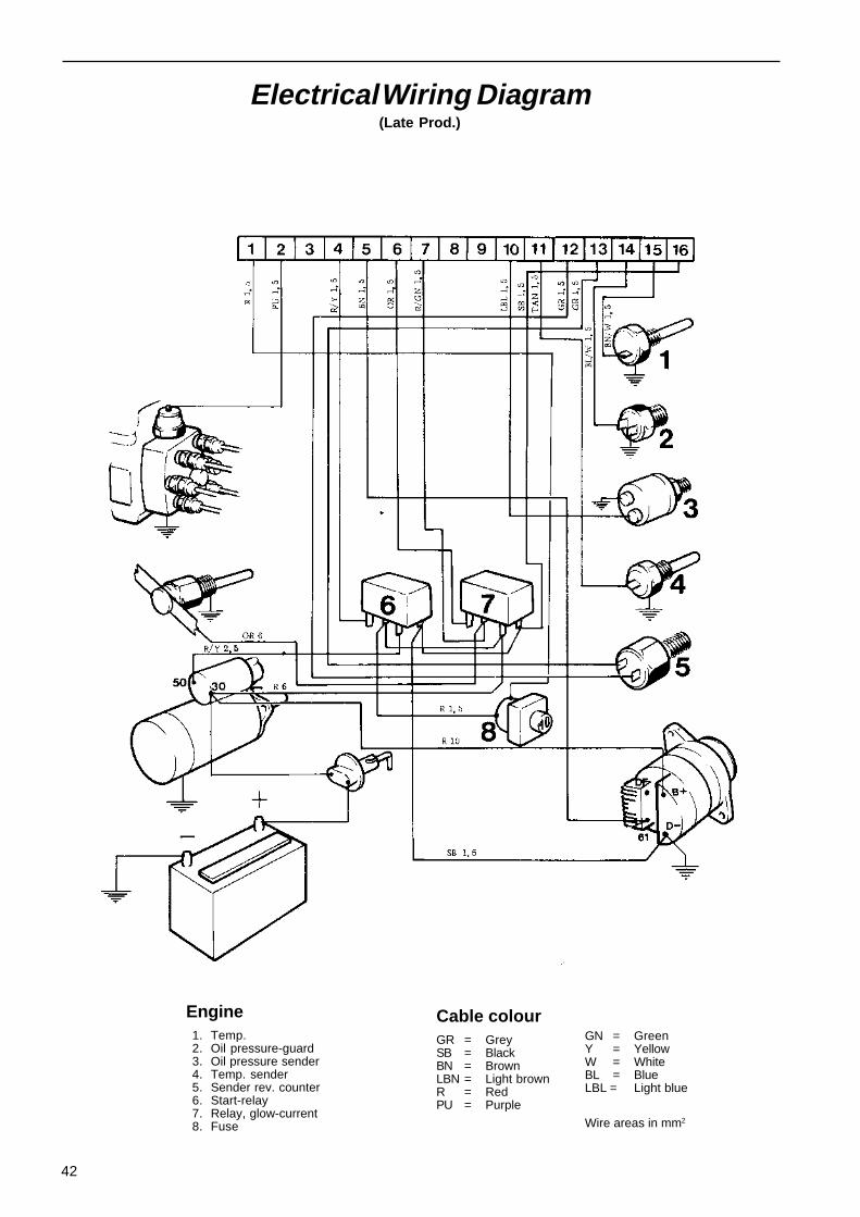
42
Electrical Wiring Diagram(Late Prod.)
Engine1. Temp.2. Oil pressure-guard3. Oil pressure sender4. Temp. sender5. Sender rev. counter6. Start-relay7. Relay, glow-current8. Fuse
Cable colourGR = GreySB = BlackBN = BrownLBN = Light brownR = RedPU = Purple
GN = GreenY = YellowW = WhiteBL = BlueLBL = Light blue
Wire areas in mm2

43
Electrical wiring diagram(Late. Prod)
Flying bridge
1. Printed circuit card2. Rev. counter3. Switch for instrument lighting4. Push button5. Alarm6. Key switch

44
Fault Finding Table
Main switch not closed. Batterydischarged. Break in cable or mainfuse block. Faulty glow plugs.
Fuel tank empty. Fuel cock closed.Fuel filter blocked.
Water or impurities in fuel. Faultyinjectors. Air in fuel system.
Faulty rev. counter. Boat loadedabnormally. Air cleaner blocked.Fouling on boat bottom or outboardmechanism.
Propeller damaged.
Coolant level too low, V-belts bro-ken or slipping.Obstruction in sea-water filter,cooling water intake, oil cooler,cooling jackets or heat exchanger.Sea-water pump impeller fault.Thermostats faulty.
Engine doesnot start
Engine stops Engine doesnot reach cor-rect workingspeed on fullthrottle
Engine runs ir-regularly or vi-brates abnor-mally
Engine be-comes abnor-mally hot
CAUSE OF TROUBLE
X
X
X
X
X X
X
X X
X
Special Tools
9991867
884533
884635 Tool for removing oil cooler insert (from andincluding engine no 1070)
Drift for removing and fitting bushing in rocker lever
Puller for polygon hub on crankshaft

45
9996271
Drift for fitting bearing in circulation pump
Drift for fitting seal in circulation pump
Retainer for dial indicator when checking height of lin-er flanges above cylinder block face
Puller for crankshaft gear
Press tool for fitting crankshaft gear and polygon
Puller for camshaft gear
Drift for removing valve guides
Drift for fitting valve guides
Installing ring for piston
Drift for removing and fitting gudgeon pin bushings
9992268
9992270
9992479
9992658
9996404
9992679
9992818
9995028
9995031

46
Press tools (two) for cylinder liners when measuringheight of cylinder liners
Puller for oil pump drive gear
Drift for fitting bearings and seal rings in seawaterpump
Plate for cylinder liner puller. Should be supplementedwith yoke from 884551 {MD5) and screw and nut from884231 (MD21 -32)
Holder for indicator instrument for injection anglemeasurement
Indicator gauge
Test pressure device for cylinder head
Connection washer for test pressure cylinder head
Sealing washers for test pressure cylinder head(19 pcs)
9996272
9996273
884347
884602+
884551+
884231
884612
884151
9996662
9996531
9996532

47
AQD40, TMD40 AQAD40, TAMD40
Technical DataGeneralType designation ................................................................................. AQD40, AQAD40, TAMD40
TMD40, MD40,Number of cylinders ............................................................................ 6Cylinder diameter ................................................................................ 92.015 mm, 3.62264 inStroke .................................................................................................. 90 mm, 3.54331 inDisplacement, total .............................................................................. 3.59 dm3, 220 in3
Compression ratio ............................................................................... 21:1Compression pressure at starter motor speed, 4 r/s (240 r/min) ........ 2.5 MPa (25 kp/cm2) 355 lbs/in2
Order of firing (No. 6 cylinder nearest flywheel) .................................. 1-5-3-6-2-4Direction of rotation (viewed from front) .............................................. ClockwiseOutput ................................................................................................. See applicable engine diagramTorque ................................................................................................. See applicable engine diagram
Engine Power Governor Maxlever overrun unloaded
speed r/m speed r/mPump settings ...................................................................... MD40A C-output 3000 3190–3290
MD40A B-output 3600 3980–4080MD40A C-output 3000 3190–3290MD40A B-output 3600 3980–4080
TMD40A B-output 3600 4000–4050TMD40A B-output 3600 3980–4080TMD40A B-output 3600 3900–4080TMD40A C-output 3000 3190–3290TMD40B B-output 3600 3980–4080
TAMD40A B-output 3600 3980–4080TAMD40A C-output 3000 3190–3290TAMD40B B-output 3600 3980–4080TAMD40B C-output 3250 3730–3830
Low idling ............................................................................................ 10–11.6 r/s (600–700 r/m)Weight, engine without outboard drive or reversing gear about ........... 400 kg 881.6 lbs (TAMD40, 440 kg, 968 lbs).
Supercharger Pressure
Supercharging pressure (measured in the inlet manifold) at100 % load and full throttle and with an air temperature ofplus 20°C. If the measurement is made at some other tem-perature, the measured pressure must be corrected in ac-cordance with the diagram on page 23.
Curve 1 = Lowest supercharging pressure at an output inaccordance with Curve C of the engine diagram.
Curve 2 = Lowest supercharging pressure at an output inaccordance with Curve B of the engine diagram.
A considerably lower pressure is obtained at less than fulloutput.
Turbo-CompressorMake and type (AQD40, TMD40) ........................................................ KKK K26-2470/10.7Make and type (AQAD40, TAMD40) .................................................... KKK K26-2664 GA 12.71Lubrication system .............................................................................. Pressure lubricationCooling system ................................................................................... Fresh-water coolingAxial clearance, max ........................................................................... 0.16 mm (0.00630 in)Radial clearance, max. (compressor side) .......................................... 0.42 mm (0.01654 in)
48
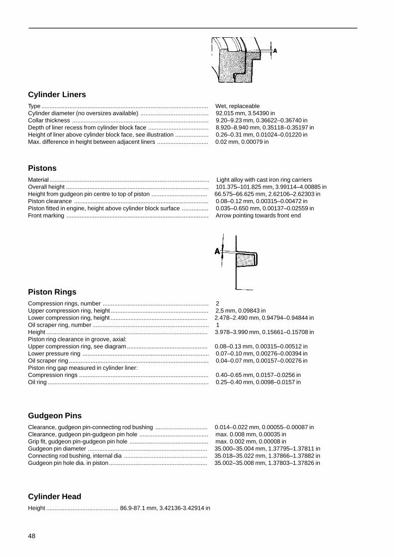
Cylinder LinersType ..................................................................................................... Wet, replaceableCylinder diameter (no oversizes available) ......................................... 92.015 mm, 3.54390 inCollar thickness .................................................................................. 9.20–9.23 mm, 0.36622–0.36740 inDepth of liner recess from cylinder block face .................................... 8.920–8.940 mm, 0.35118–0.35197 inHeight of liner above cylinder block face, see illustration .................... 0.26–0.31 mm, 0.01024–0.01220 inMax. difference in height between adjacent liners ............................... 0.02 mm, 0.00079 in
PistonsMaterial ................................................................................................ Light alloy with cast iron ring carriersOverall height ...................................................................................... 101.375–101.825 mm, 3.99114–4.00885 inHeight from gudgeon pin centre to top of piston .................................. 66.575–66.625 mm, 2.62106–2.62303 inPiston clearance ................................................................................. 0.08–0.12 mm, 0.00315–0.00472 inPiston fitted in engine, height above cylinder block surface ................ 0.035–0.650 mm, 0.00137–0.02559 inFront marking ...................................................................................... Arrow pointing towards front end
Piston RingsCompression rings, number ................................................................ 2Upper compression ring, height ........................................................... 2,5 mm, 0.09843 inLower compression ring, height ........................................................... 2.478–2.490 mm, 0.94794–0.94844 inOil scraper ring, number ...................................................................... 1Height .................................................................................................. 3.978–3.990 mm, 0.15661–0.15708 inPiston ring clearance in groove, axial:Upper compression ring, see diagram................................................. 0.08–0.13 mm, 0.00315–0.00512 inLower pressure ring ............................................................................ 0.07–0.10 mm, 0.00276–0.00394 inOil scraper ring .................................................................................... 0.04–0.07 mm, 0.00157–0.00276 inPiston ring gap measured in cylinder liner:Compression rings .............................................................................. 0.40–0.65 mm, 0.0157–0.0256 inOil ring ................................................................................................. 0.25–0.40 mm, 0.0098–0.0157 in
Gudgeon PinsClearance, gudgeon pin-connecting rod bushing ................................ 0.014–0.022 mm, 0.00055–0.00087 inClearance, gudgeon pin-gudgeon pin hole .......................................... max. 0.008 mm, 0.00035 inGrip fit, gudgeon pin-gudgeon pin hole ................................................ max. 0.002 mm, 0.00008 inGudgeon pin diameter ......................................................................... 35.000–35.004 mm, 1.37795–1.37811 inConnecting rod bushing, internal dia ................................................... 35.018–35.022 mm, 1.37866–1.37882 inGudgeon pin hole dia. in piston ............................................................ 35.002–35.008 mm, 1.37803–1.37826 in
Cylinder HeadHeight ............................................ 86.9-87.1 mm, 3.42136-3.42914 in

49
Crankshaft with BearingsCrankshaft end float ............................................................................ 0.10–0.31 mm, 0.00394–0.01220 inMain bearings, radial clearance ........................................................... 0.04–0.09 mm, 0.00157–0.00354 in
Main Bearing Journals
Diameter, standard .............................................................................. 69.987–70.000 mm, 2.74788–1.75591 inUndersize 0.25 mm, 0.01 in ................................................................. 69.737–69.750 mm, 2.74204–2.74607 in0.50 mm, 0.02 in .................................................................................. 69.487–69.500 mm, 2.73220–2.73623 in0.75 mm, 0.03 in .................................................................................. 69.237–69.250 mm, 2.72586–2.72639 inWith (A in figure) on crankshaft for pilot bearing withseparate thrust washers:Standard .............................................................................................. 35.975–36.025 mm, 1.41634–1.418230 inOversize 0.2 mm 0.00787 in
(thrust washers 0.1 mm 0.00394 in oversize) .................................. 36.175–36.225 mm, 1.42421–1.42617 inOversize 0.4 mm, 0.01575 in
(thrust washers 0.2 mm 0.00787 in oversize) .................................. 36.375–36.425 mm, 1.43208–1.43403 in
Big-End Journals
Big-end bearings, radial clearance ...................................................... 0.034–0.078 mm, 0.00134–0.00307 inLength of bearing journals ................................................................... 38.95–39.05 mm, 1.53346–1.53740 inDiameter, standard .............................................................................. 56.487–56.500 mm, 2.22390–2.22441 inUndersize, 0,25 mm 0,01 in ................................................................ 56.237–56.250 mm, 2.21012–2.21063 in
0.50 mm, 0.02 in ............................................................... 55.987–56.000 mm, 2.19685–2.20472 in0.75 mm, 0.03 in ............................................................... 55.737–55.750 mm, 2.18307–2.19094 in
Main and Big-End Bearing Shells
Main bearing shells Big-End bearing shellsThickness, standard ....................................... 2.970–2.979 mm, 1.724–1.733 mm,
0.11683–0.11728 in 0.06787–0.06819 inUndersize, 0.25 mm, 0.01 in .......................... 3.095–3.104 mm, 1.849–1.858 mm,
0.12185–0.12221 in 0.07280–0.07315 in0.50 mm, 0.02 in .......................... 3.220–3.229 mm, 1.974–1.983 mm,
0.12677–0.12712 in 0.07771–0.07797 in0.75 mm, 0.03 in .......................... 3.345–3.354 mm, 2.099–2.108 mm,
0.13169–0.13205 in 0.086264–0.08299 in
Connecting RodsMarked 1 to 6.End float, connecting rod – crankshaft ................................................ 0.15–0.30 mm, 0.00591–0.01181 inDia. Big-end bearing shell recess ........................................................ 60.00–60.013 mm, 2.36220–2.36271 inDia. Connecting rod bearing bushing recess ....................................... 39.000–39.039 mm, 1.53543–1.53697 inDia. Gudgeon pin bushing ................................................................... See ”Gudgeon Pins’’
R = 3.9 mm

50
FlywheelFlywheel ring gear ............................................................................... 115 teeth
CamshaftDrive .................................................................................................... GearNumber of bearings ............................................................................. 7Dia. of bearing journals ........................................................................ 52.981–53.000 mm, 2.08586–2.08661 inEnd float .............................................................................................. 0.04–0.12 mm, 0.00157–0.00433 inRadial clearance ................................................................................. 0.025–0.063 mm, 0.00098–0.000248 in
Checking camshaft setting (cold engine and valve clearance = 0)
With flywheel at 10° after TDC, the inlet valve forNo. 1 cylinder should have opened ...................................................... 2.1 mm, 0.08267 inLift, inlet ............................................................................................... 7.26 mm, 0.28583 inexhaust ............................................................................................... 7.54 mm, 0.29685 in
Camshaft BearingsBearing diameter ................................................................................. 53.025–53.044 mm, 2.08759–2.08834 in
Auxiliary Drive GearsBacklash ............................................................................................. 0.03–0.17 mm, 0.00118–0.00669 inRadial clearance of idler gear .............................................................. 0.03–0.09 mm, 0.00118–0.00354 inEnd float for idler gear ......................................................................... 0.03–0.15 mm, 0.00118–0.00591 inShaft for idler gear, dia. ........................................................................ 54.940–54.970 mm, 2.16299–2.16417 inBushing for idler gear, dia .................................................................... 55.000–55.030 mm, 2.16535–2.16653 inNumber of Teeth: Crankshaft Gear ..................................................... 33
Idler Gear ............................................................... 41Camshaft Gear ....................................................... 66Drive gear for injection/sea-water pump ................. 66
Valve Lay-Out and Cylinder NumberingValves, A = INLET, B = EXHAUST
Valve SystemValves Inlet ExhaustDisc diameter ................................................. 41.8 mm, 1.64567 in 35.7 mm, 1.40551 inStem diameter ................................................ 7.955–7.970 mm, 7.925–7.940 mm,
0.31319–0.31378 in 0.31200–0.31259 inValve seat angle ............................................. 29.5° 44 5°Seat angle in cylinder head ............................ 30° 45°Clearance, (cold engine or atworking temperature) ..................................... 0.40 mm, 0.01575 in 0.40 mm, 0.01575 in

51
Valve seats
Valve seat Valve seat Recess
Inlet Exhaust
Diameter, standard (measurement A) ............. 43.064–43.080 mm 37.064–37.080 mm1.69543–1.69606 in 1.45921–1.45984 in
Oversize ......................................................... 43.264–43.280 mm 37.264–37.280 mm1.70370–1.70393 in 1.46709–1.46771 in
Height (measurement B) ................................. 7.3–7.35 mm 7.5–7.55 mm0.28740–0.28937 in 0.29528–0.29725 in
Valve Seat Recess:Dia. standard (measurement C) ...................... 43.000–43.025 mm 37.000–37.025 mm
1.69291–1.69350 in 1.45669–1.45767 inOversize ......................................................... 43.200–43.225 mm 37.200–37.225 mm
1.70078–1.70137 in 1.46456–1.46554 inDepth (measurement D) ................................. 10.5–10.8 mm 10.25–10.5 mm
0.4134–0.4254 in 0.40354–0.4134 inBottom radius of recess (measurement R) ...... 0.4–0.5 mm 0.4–0.5 mm
0.01575–0.01969 in 0.01575–0.01969 inThe distance between the valve disc andthe cylinder head face should be ..................... 1.1–1.6 mm 0.85–1.35 mm
0.04331–0.06299 in 0.03346–0.04348 in
Valve Guides
Length ................................................................................................. 59 mm 2.32283 inInternal dia. (fitted) ............................................................................... 8.000–8.015 mm, 0.31496–0.31555 inReplacement type ............................................................................... 8.000–8.022 mm, 0.31496–0.32362 inHeight above cyl. head spring plane .................................................... 18 mm, 0.70866 inClearance, valve stem - valve guide:Inlet valves .......................................................................................... 0.030–0.060 mm, 0.00012–0.00024 inExhaust valves ................................................................................... 0.060–0.090 mm, 0.00024–0.00035 in
Valve Springs
Length unloaded .................................................................................. 46 mm, 1.81102 inLength with loading of: 267–312 N (27.2–31.8 kp) 60–70 lbs .............. 40 mm, 1.57480 inLength with loading of: 767–852 N (78.2–86.2 kp) 170–190 lbs ........... 30 mm, 1.18110 inLength fully compressed, max ............................................................. 28.8 mm, 1.13386 in
Rocker Arm Mechanism
Rocker arm bushing, dia. after pressing in and machining .................. 22.020–22.041 mm, 0.86732–0.86775 in
Lubricating SystemOil pressure, hot engine, operating speed, lubricating oil .................... 0.42–0.5 MPa (4.2–5 kp/cm2)
59.7–71.1 lbf/inOil pressure, hot engine, operating speed, piston; cooling oil .............. 0.22–0.3 MPa (2.2–3 kp/cm2)
31.3–42,6 lbf/in2
Oil quality in accordance with API-system .......................................... CD (For Service DS)Oil viscosity, above +10°C 50°F ......................................................... SAE 20W/301)
under +10°C 50°F ............................................................................... SAE 10W2)
1) Volvo Penta CD Oil, Double Grade.2) Volvo Penta CD Oil, Single Grade

52
Oil capacity, including oil cleaner:No engine inclination ........................................................................... 11 dm3 (litre) 2.42 imp.gal, 2.9 US gal15° engine inclination .......................................................................... 10.5 dm3 (litre) 2.3 imp.gal. 2.77 US galLubricating oil pump, type .................................................................... GearEnd float, pump gear ........................................................................... 0.07–0.15 mm0.00276–0.00591 inBacklash, pump gear .......................................................................... 0.15–0.35 mm0.00591–0.01378 inDia., idler gear bearing sleeve ............................................................. 55.03–55.06 mm, 2.1665–2.1677 inBushing for idler gear .......................................................................... 54.07–55.00 mm, 2.12874–2.16535 inRadial clearance for idler gear ............................................................. 0.03–0.09 mm, 0.00118–0.00354 inDia., oil pump bushings ....................................................................... 16.016–16.034 mm, 0.63055–0.63126 inClearance, thrust washer – oil pump drive gear .................................. 0.02–0.08 mm, 0.00079–0.00315 inNumber of teeth on oil pump drive gear ............................................... 39Oil pump idler ...................................................................................... 36Crankcase ventilationValve opens at ..................................................................................... 0,8 kPa (0.008 kp/cm2), 0.114 lbf/in2
Fuel SystemDirection of rotation of injection pump, seen from the front .................. Anti-clockwiseOrder of injection ................................................................................. 1-5-3-6-2-4Low idling ............................................................................................ 10–11.6 r/s (600–700 r/m)High idling B-output ............................................................................. 66.6–67.5 r/s (4000–4050 r/m)C-output .............................................................................................. 53.2–54.8 r/s (3200–3300 r/m)Feed Pressure ..................................................................................... 14.7–27.5 kPa (0.15–0.28 kp/cm2)
2.13-4.98 lbf/in2
Injection Pump
Make, type ........................................................................................... Bosch EP/VE 6/11 FSetting ................................................................................................. MD40 0-1°, TMD40 2-3°,
TAMD40 1-2° after TDC with 1 mm plunger liftFeed Pump .......................................................................................... S.E.V. 70 VE
Fuel Filter
Type designation ................................................................................. FJ/DBR 1 W6/225
Injectors
Nozzle Holders, make and type .......................................................... KBE 36 S 2/13Nozzles ............................................................................................... DN 0 SD 193Type of Nozzle .................................................................................... Pintle NozzleInjector compl. number marking ........................................................... 0 432 297 032Opening pressure ................................................................................ 17.7 MPa (175 kp/cm2, 2489 lbf/in2)Adjusting pressure (new spring) ......................................................... 18.0–18.8 MPa (183–192 kp/cm2)
2602.8-2730.8 lbf/in2
Cooling systemType ..................................................................................................... OverpressureCapacity, including heat exchanger and separate expansion tank,about (AQ40, TMD40, MD40) .............................................................. 21 dm3 4.6 imp.gal. 5.5 US gal.Capacity, including heat exchanger and separate expansion tank,about (AQAD40, TAMD40) .................................................................. 23 dm3 5.0 imp.gal. 6.6 US gal.
Thermostats
Type ..................................................................................................... WaxNumber ............................................................................................... 2The thermostat with an air valve should open at ................................. 68–72°C, 154.4–161.6°FFully open at ........................................................................................ 78–82°C, 172.4–179.6°FThe thermostat without an air valve should open at ............................ 74–78°C, 165.2–172.4°FFully open at ........................................................................................ 84–88°C, 183.2–190.4°F

53
Electrical SystemSystem voltage ................................................................................... 12 VBattery capacity .................................................................................. 114 AhDensity of battery electrolyte:Fully charged battery ........................................................................... 1.275–1.285Battery to be recharged at ................................................................... 1.230AlternatorVoltage/max. current ............................................................................ 14 V/50 AOutput ................................................................................................. 700 WStarter MotorOutput ................................................................................................. 2.5 kW (3.4 hp)Brush length ........................................................................................ min. 10 mm 0.3937 inBrush spring force ............................................................................... 20–25 N (2–2.5 kp) 4.41–5.51 lbGlow plug Bosch ................................................................................. RSK
Wear TolerancesCylinder Head
Height .................................................................................................. min. 86.7 mm, 3.4134 in
Cylinders
Cylinder liners and pistons must be replaced whenwear amounts to .................................................................................. 0.25–0.30 mm, 0.0098–0.0118 in.
Crankshaft
Permissible out-of-round on main and big-end bearing journals, max. . 0.04 mm, 0.001575 inMax. permissible taper on main and big-end journals .......................... 0.05 mm, 0.00197 inMax. end float on crankshaft ............................................................... 0.40 mm, 0.01575 in
Valves
Valve stems, max. permissible wear ................................................... 0.02 mm, 0.00079 inMax. permissible clearance between valve stem and valve guideInlet valves .......................................................................................... 0.15 mm, 0.00591 inExhaust valves ................................................................................... 0.17 mm, 0.00669 inThe valve edge should be, min. inlet .................................................... 1.5 mm, 0.05906 inexhaust ............................................................................................... 1.3 mm, 0.05118 inThe valve seat may be ground until the distance from thevalve disc (new valve) to the cylinder head surface is:Inlet ...................................................................................................... 1.8 mm, 0.07087 inExhaust ............................................................................................... 1.55 mm, 0.06103 in
Camshaft
Max. permissible wear ......................................................................... 0.05 mm, 0.00197 inBearings, max. permissible wear ........................................................ 0.05 mm, 0.00197 in

54
Tightening Torques
Nm (kpm) ft lbsCylinder head bolts* ....................................... 130 (13) 94.0
Tightening diagram, Cylinder Head Bolts.
* Note! The bolt threads should be moistened with rust proofing medium (detail number 282036) before being fitted. The boltsshould be tightened in accordance with the diagram in stages, the tightening torques for these stages being 30, 90 and 130Nm (3, 9, 13 kpm) 22, 65, 94 ft/lbs.NOTE! The bolts should be re-tightened after 1 h test run (warm or cold engine).
Nm (kpm) ft lbsMain bearings ................................................ 180, 140* (18) (14)* 130.2 (101.2)*Big-end bearings ............................................ 113 (11.3) 81.7Rocker arm shaft ........................................... 23 (2.3) 16.6Thrust washer, camshaft bearings ................. 23 (2.3) 16.6Camshaft gear ............................................... 80 (8) 57.8Bearing journal for idler gear,auxiliary drive gears ....................................... 23 (2.3) 16.6Engine speed sender ..................................... 40 (4) 28.9Oil filter with oiled sealing ring ........................ 25 (2.5) 18.0Lubricating oil pump bracket .......................... 23 (2.3) 16.6Rocker arm cover .......................................... 10 (1) 7.2Auxiliary drive gear casing ............................. 20 (2) 14.5Oil sump ........................................................ 15 (1.5) 11.0Drain plug, oil sump ....................................... 60 (6) 43.5Flywheel casing ............................................. 46 (4.6) 33.3Flywheel ........................................................ 105 115** (10.5) (11.5)** 76 (82)**Vibration damper, attaching bolts ................... 25 (2.5) 18Centre bolt for hub ......................................... 180 (18) 130Injection pump, hub for drive .......................... 65 (6.5) 47Gearwheel/driver ........................................... 25 (2.5) 18Pressure valve retainers ................................ 40 (4) 29Stop solenoid ................................................. 43 (4.3) 31Injector, attaching nut ..................................... 23 (2.3) 16.5Glow plug ...................................................... 20 (2) 14.5
* The low value is current for engines with no 2201 and following.** The high value is current for engines with no 31816 and following.

Report form
Do you have any complaints or other comments about this manual? Please makea copy of this page, write your comments down and post it to us. The address is atthe bottom of the page. We would prefer you to write in English or Swedish.
From: ............................................................................
......................................................................................
......................................................................................
......................................................................................
Refers to publication: .............................................................................................................................................
Publication no.: ..................................................................... Issued: ....................................................................
Suggestion/reasons: ..............................................................................................................................................
..............................................................................................................................................................................
..............................................................................................................................................................................
..............................................................................................................................................................................
..............................................................................................................................................................................
..............................................................................................................................................................................
..............................................................................................................................................................................
..............................................................................................................................................................................
..............................................................................................................................................................................
Date: ...........................................................
Name: .........................................................
AB Volvo PentaCustomer Support
Dept. 42200SE-405 08 Gothenburg
Sweden

77
52
37
0-2
E
nglis
h 1
0-1
99
9