april 20th, 2007 rensselaer radio frequency integrated circuits lab. overview: trends and...
Post on 19-Dec-2015
213 views
TRANSCRIPT

April 20th, 2007April 20th, 2007Rensselaer Radio Frequency Integrated Circuits Lab.Rensselaer Radio Frequency Integrated Circuits Lab.
Overview: Trends and Implementation Challenges for
Multi-Band/Wideband Communication
Mona Mostafa Hella
Assistant Professor, ESCE DepartmentRensselaer Polytechnic Institute

April 20th, 2007April 20th, 2007Rensselaer Radio Frequency Integrated Circuits Lab.Rensselaer Radio Frequency Integrated Circuits Lab.
•Any integrated circuit used in the frequency range: 100 MHz to 3 GHz (till 6GHz can sometimes be considered RF). Currently we are having mm-wave circuits in Silicon (17GHz, 24GHz, 60GHZ, and 77GHz)
•Generally RFIC’s contain the analog front end of a radio transceiver, or some part of it.
•RFIC’s can be the simplest switch, up to the whole front end of a radio transceiver.
•RFIC’s are fabricated in a number of technologies: Si Bipolar, Si CMOS, GaAs HBT, GaAs MESFET/HEMT, and SiGe HBT are today’s leading technologies.
We are going to design in either CMOS, or SiGe.
What is RFIC?

April 20th, 2007April 20th, 2007Rensselaer Radio Frequency Integrated Circuits Lab.Rensselaer Radio Frequency Integrated Circuits Lab.
RF Transmitter RF Receiver
Basic Wireless Transceivers

April 20th, 2007April 20th, 2007Rensselaer Radio Frequency Integrated Circuits Lab.Rensselaer Radio Frequency Integrated Circuits Lab.
The last 10 years in wireless systems
April 20th, 2007April 20th, 2007Rensselaer Radio Frequency Integrated Circuits Lab.Rensselaer Radio Frequency Integrated Circuits Lab.
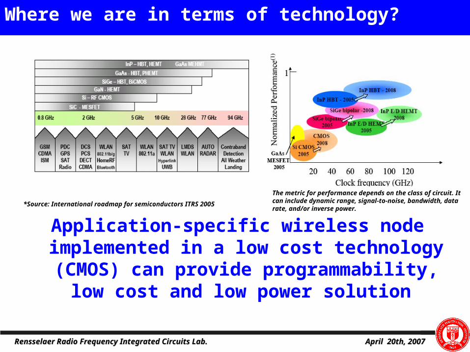
Where we are in terms of technology?
The metric for performance depends on the class of circuit. It can include dynamic range, signal-to-noise, bandwidth, data rate, and/or inverse power.
*Source: International roadmap for semiconductors ITRS 2005
Application-specific wireless node implemented in a low cost technology (CMOS) can provide
programmability, low cost and low power solution

April 20th, 2007April 20th, 2007Rensselaer Radio Frequency Integrated Circuits Lab.Rensselaer Radio Frequency Integrated Circuits Lab.
The next 10 years !!

April 20th, 2007April 20th, 2007Rensselaer Radio Frequency Integrated Circuits Lab.Rensselaer Radio Frequency Integrated Circuits Lab.
Spectrum Utilization

April 20th, 2007April 20th, 2007Rensselaer Radio Frequency Integrated Circuits Lab.Rensselaer Radio Frequency Integrated Circuits Lab.
A Cognitive Radio (CR) can be defined as “a radio that senses and is aware of its operational environment and can dynamically adapt to utilize radio resources in time, frequency and space domains on a real time basis, accordingly to maintain connectivity with its peers while not interfering with licensed and other CRs”.
Cognitive radio can be designed as an enhancement layer on top of the Software Defined Radio (SDR) concept.
Introduction to Cognitive Radio

April 20th, 2007April 20th, 2007Rensselaer Radio Frequency Integrated Circuits Lab.Rensselaer Radio Frequency Integrated Circuits Lab.
Basic Non-Cognitive Radio Architecture:
Cognitive Radio architecture:
Networked Device
AntennaCoupling
Data Modem
ProcessorTransmitter
and Receiver
Wireless Data Transceiver Subsystem Module
Spectrum Scanning and Interference Avoidance Module
Data ModemProcessor
Networked Device
Scanning Engine
SpectrumAnalysisEngine
Channel Pooling Server
Transmitterand Receiver
Antenna Sharing Module
Data ModemProcessorTransmitter
and Receiver
Introduction to Cognitive Radio-2

April 20th, 2007April 20th, 2007Rensselaer Radio Frequency Integrated Circuits Lab.Rensselaer Radio Frequency Integrated Circuits Lab.
Window of Opportunity
Time (min)
Fre
quen
cy (
Hz)
Existing spectrum policy forces spectrum to behave like a fragmented
disk Bandwidth is expensive and good
frequencies are taken
Unlicensed bands – biggest innovations in spectrum efficiency
Recent measurements by the FCC in the US show 70% of the allocated spectrum is not utilized
Time scale of the spectrum occupancy varies from msecs to hours

April 20th, 2007April 20th, 2007Rensselaer Radio Frequency Integrated Circuits Lab.Rensselaer Radio Frequency Integrated Circuits Lab.
CR Definitions

April 20th, 2007April 20th, 2007Rensselaer Radio Frequency Integrated Circuits Lab.Rensselaer Radio Frequency Integrated Circuits Lab.
Today “spectrum“ is regulated by governmental agencies, e.g. FCC) “Spectrum“ is assigned to users or licensed to them on a long term
basis normally for huge regions like whole countries Doing so, resources are wasted Vision: Resources are assigned where and as long as they are needed,
spectrum access is organized by the network (i.e. by the end users) A CR is an autonomous unit in a communications environment. In
order to use the spectral resource most efficiently, it has to - be aware of its location - be interference sensitive- comply with some communications etiquette- be fair against other users- keep its owner informed
CR should Sense the spectral environment over a wide bandwidth detect presence/absence of primary users Transmit in a primary user band only if detected as unused Adapt power levels and transmission bandwidths to avoid interference to
any primary user

April 20th, 2007April 20th, 2007Rensselaer Radio Frequency Integrated Circuits Lab.Rensselaer Radio Frequency Integrated Circuits Lab.
Software Radio (SR): An ideal SR directly samples the antenna output.
1) According to J. Mitola, 2000
Digital Radio (DR): The baseband signal processing is invariably implemented on a DSP.
Software Defined Radio (SDR): An SDR is a presently realizable version of an SR: Signals are sampled after a suitable band selection filter.
Cognitive Radio (CR): A CR combines an SR with a PDA
tran
smit
rece
ive radio frontend
radiofrequency
RF
basebandprocessing
to u
ser
fro
m u
ser
analog-to-digitalconversion
A/D
dataprocessing
control
(parametrization)
CR Definitions

April 20th, 2007April 20th, 2007Rensselaer Radio Frequency Integrated Circuits Lab.Rensselaer Radio Frequency Integrated Circuits Lab.
D/AD/APAPAPA
LNA A/D
IFFT
FFT
ADAPTIVELOADING
INTERFERENCEMEAS/CANCEL
MAE/POWER CTRL
CHANNELSEL/EST
TIME, FREQ,SPACE SEL
LEARN ENVIRONMENT
QoS vs.RATE
FEEDBACKTO CRs
IFFTIFFT
FFTFFT
ADAPTIVELOADINGADAPTIVELOADING
INTERFERENCEMEAS/CANCELINTERFERENCEMEAS/CANCEL
MAE/POWER CTRL
CHANNELSEL/EST
TIME, FREQ,SPACE SEL TIME, FREQ,SPACE SEL
LEARN ENVIRONMENT
LEARN ENVIRONMENT
QoS vs.RATE
QoS vs.RATE
FEEDBACKTO CRs
FEEDBACKTO CRs
Sensing Radio
• Wideband Antenna, PA and LNA
• High speed A/D & D/A, moderate resolution
• Simultaneous Tx & Rx
• Scalable for MIMO
Physical Layer
• OFDM transmission
• Spectrum monitoring
• Dynamic frequency selection, modulation, power control
• Analog impairments compensation
MAC Layer
• Optimize transmission parameters
• Adapt rates through feedback
• Negotiate or opportunistically use resources
RF/Analog Front-end Digital Baseband MAC Layer
Cognitive radio Functions

April 20th, 2007April 20th, 2007Rensselaer Radio Frequency Integrated Circuits Lab.Rensselaer Radio Frequency Integrated Circuits Lab.
RF Front-End Schematic
DigitalProcessor
A/D
D/A
Baseband amplifiers and filters
Up & down frequency converters
RF filters
Digital
Mixed
Front-End: Analog/RF
Waveguide filters
Low-noise amplifierLOLow-noise amplifierLO
Power amplifier
LO
Local oscillators
Power amplifier
LO
Local oscillators
Analog & Digital
Converters

April 20th, 2007April 20th, 2007Rensselaer Radio Frequency Integrated Circuits Lab.Rensselaer Radio Frequency Integrated Circuits Lab.
amplifier
Wideband down-
converter
filter
Wideband or
multiband antenna
Agile LO
Wideband power
amplifier
Wideband up-converter
filter
Wideband LNA
amplifier
Program-mable Filter
Program-mable Filter
Agile LO
switch
End UserEquipment
DigitalProcessor
A/D
D/A
•Baseband switch•Crypto•Modem
RF Front-End Challenges

April 20th, 2007April 20th, 2007Rensselaer Radio Frequency Integrated Circuits Lab.Rensselaer Radio Frequency Integrated Circuits Lab.
Motivation
Intelligence and military application require an
application-specific low cost, secure wireless systems. An adaptive spectrum-agile MIMO-based wireless node
will require application-specific wireless system: Reconfigurable Radio (operating frequency
band, bit rate, transmission power level, etc) Wide frequency coverage and agility Work independent of commercial infrastructure Large instantaneous bandwidth

April 20th, 2007April 20th, 2007Rensselaer Radio Frequency Integrated Circuits Lab.Rensselaer Radio Frequency Integrated Circuits Lab.
A/D converter:
– High resolution
– Speed depends on the application
– Low power ~ 100mWs
RF front-end:
– Wideband antenna and filters
– Linear in large dynamic range
– Good sensitivity
Interference temperature:
– Protection threshold for licensees
– FCC: 2400-2483.5 MHz band is empty if:
Need to determine length of measurements
0 0.5 1 1.5 2 2.5
x 109
-90
-85
-80
-75
-70
-65
-60
-55
-50
-45
-40
Frequency (Hz)
Sig
nal
Str
en
gth
(d
B)
TV bands
Cell
PCS
0 0.5 1 1.5 2 2.5
x 109
-90
-85
-80
-75
-70
-65
-60
-55
-50
-45
-40
0 0.5 1 1.5 2 2.5
x 109
-90
-85
-80
-75
-70
-65
-60
-55
-50
-45
-40
Frequency (Hz)
Sig
nal
Str
en
gth
(d
B)
TV bands
Cell
PCS
Frequency (Hz)
Sig
nal
Str
en
gth
(d
B)
TV bands
Cell
PCS
System Challenges

April 20th, 2007April 20th, 2007Rensselaer Radio Frequency Integrated Circuits Lab.Rensselaer Radio Frequency Integrated Circuits Lab.
Receiver
• Wideband sensing
• Different primary user signal powers and types
• Channel uncertainty between CR and primary user
Transmitter
• Wideband transmission
• Adaptation
• Interference with primary user
System Challenges
April 20th, 2007April 20th, 2007Rensselaer Radio Frequency Integrated Circuits Lab.Rensselaer Radio Frequency Integrated Circuits Lab.
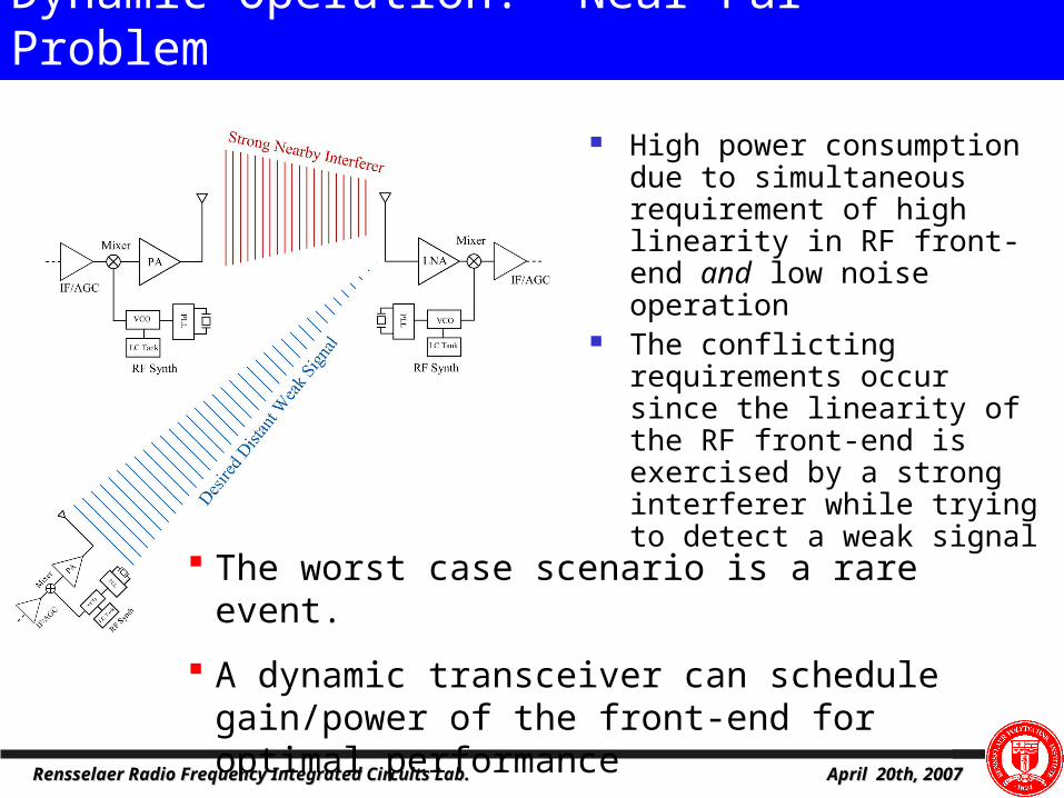
High power consumption due to simultaneous requirement of high linearity in RF front-end and low noise operation
The conflicting requirements occur since the linearity of the RF front-end is exercised by a strong interferer while trying to detect a weak signal
The worst case scenario is a rare event.
A dynamic transceiver can schedule gain/power of the front-end for optimal performance
Dynamic Operation: Near-Far Problem

April 20th, 2007April 20th, 2007Rensselaer Radio Frequency Integrated Circuits Lab.Rensselaer Radio Frequency Integrated Circuits Lab.
Cognitive radios are expected to be powerful tools for mitigating and solving general and selective spectrum access issues (e.g. finding an open frequency band and effectively utilizing it).
Improves current spectrum utilization (Fill in unused spectrum and move away from occupied spectrum ).
Improves wireless data network performance through increased user throughput and system reliability.
More adaptability and less coordination required between wireless networks.
Advantages of CR

April 20th, 2007April 20th, 2007Rensselaer Radio Frequency Integrated Circuits Lab.Rensselaer Radio Frequency Integrated Circuits Lab.
UWB Systems

April 20th, 2007April 20th, 2007Rensselaer Radio Frequency Integrated Circuits Lab.Rensselaer Radio Frequency Integrated Circuits Lab.
Basics of UWB Signaling

April 20th, 2007April 20th, 2007Rensselaer Radio Frequency Integrated Circuits Lab.Rensselaer Radio Frequency Integrated Circuits Lab.
Definition of UWB Systems

April 20th, 2007April 20th, 2007Rensselaer Radio Frequency Integrated Circuits Lab.Rensselaer Radio Frequency Integrated Circuits Lab.
Why UWB?

April 20th, 2007April 20th, 2007Rensselaer Radio Frequency Integrated Circuits Lab.Rensselaer Radio Frequency Integrated Circuits Lab.
UWB Applications

April 20th, 2007April 20th, 2007Rensselaer Radio Frequency Integrated Circuits Lab.Rensselaer Radio Frequency Integrated Circuits Lab.
UWB Sensors

April 20th, 2007April 20th, 2007Rensselaer Radio Frequency Integrated Circuits Lab.Rensselaer Radio Frequency Integrated Circuits Lab.
UWB Sensor Architectures

April 20th, 2007April 20th, 2007Rensselaer Radio Frequency Integrated Circuits Lab.Rensselaer Radio Frequency Integrated Circuits Lab.
UWB receiver Architecture

April 20th, 2007April 20th, 2007Rensselaer Radio Frequency Integrated Circuits Lab.Rensselaer Radio Frequency Integrated Circuits Lab.
UWB receiver Architecture

April 20th, 2007April 20th, 2007Rensselaer Radio Frequency Integrated Circuits Lab.Rensselaer Radio Frequency Integrated Circuits Lab.
Multi-band OFDM UWB Architecture

April 20th, 2007April 20th, 2007Rensselaer Radio Frequency Integrated Circuits Lab.Rensselaer Radio Frequency Integrated Circuits Lab.
Multi-band OFDM UWB Radio Architecture

April 20th, 2007April 20th, 2007Rensselaer Radio Frequency Integrated Circuits Lab.Rensselaer Radio Frequency Integrated Circuits Lab.
Comparison of MB-OFDM radios

April 20th, 2007April 20th, 2007Rensselaer Radio Frequency Integrated Circuits Lab.Rensselaer Radio Frequency Integrated Circuits Lab.
UWB Components/Subsystems
April 20th, 2007April 20th, 2007Rensselaer Radio Frequency Integrated Circuits Lab.Rensselaer Radio Frequency Integrated Circuits Lab.
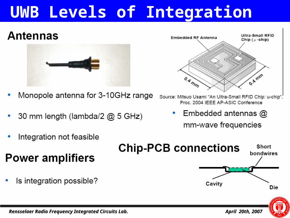
UWB Levels of Integration
April 20th, 2007April 20th, 2007Rensselaer Radio Frequency Integrated Circuits Lab.Rensselaer Radio Frequency Integrated Circuits Lab.
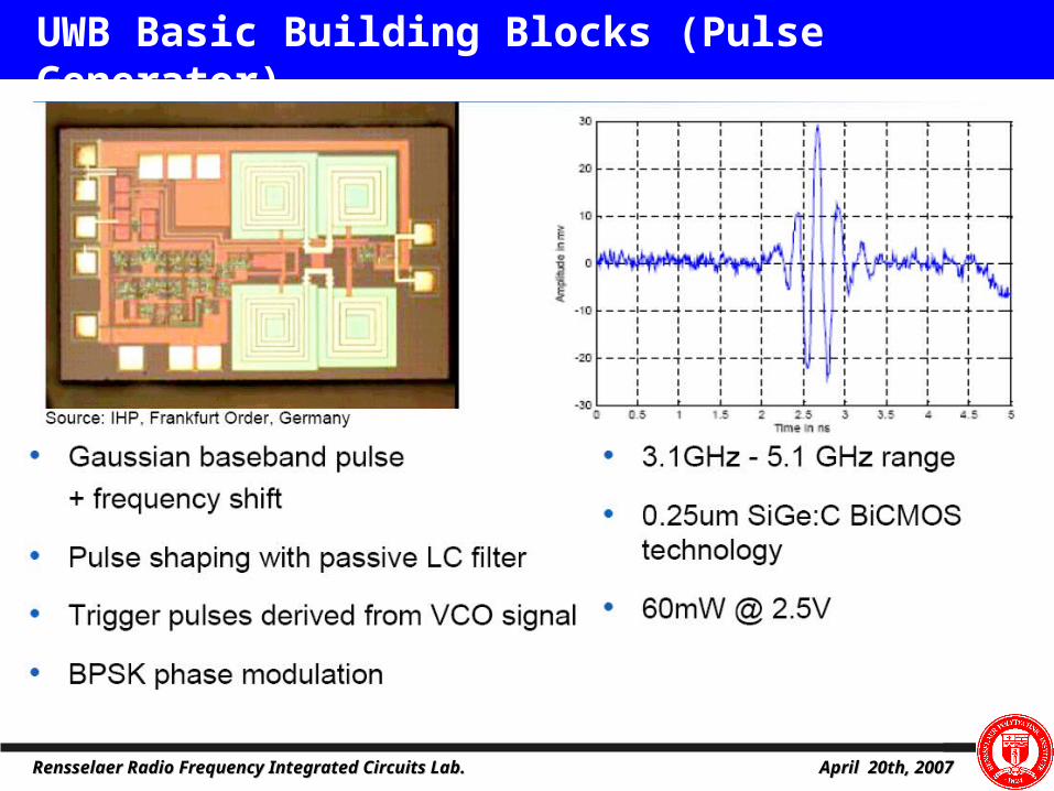
UWB Basic Building Blocks (Pulse Generator)

April 20th, 2007April 20th, 2007Rensselaer Radio Frequency Integrated Circuits Lab.Rensselaer Radio Frequency Integrated Circuits Lab.
Challenges in UWB IC Design

April 20th, 2007April 20th, 2007Rensselaer Radio Frequency Integrated Circuits Lab.Rensselaer Radio Frequency Integrated Circuits Lab.
Challenges in UWB IC Design

April 20th, 2007April 20th, 2007Rensselaer Radio Frequency Integrated Circuits Lab.Rensselaer Radio Frequency Integrated Circuits Lab.
Future Trends

April 20th, 2007April 20th, 2007Rensselaer Radio Frequency Integrated Circuits Lab.Rensselaer Radio Frequency Integrated Circuits Lab.
Future Trends; UWB Beam forming

April 20th, 2007April 20th, 2007Rensselaer Radio Frequency Integrated Circuits Lab.Rensselaer Radio Frequency Integrated Circuits Lab.
Multi-band VCO
Existing Multiband VCOs/Frequency References are based on:
Switched inductor and/or capacitor LC tanks (Extra parasitics and resistive loss degrade both tuning range and phase noise)
Frequency dividers (higher phase noise and power consumption)
MEMS resonators (non-standard process, extra processing steps, higher fabrication cost)
1/2
1/4
1/2
3.3-4.2GHz
0.825-4.2GHz
1.65-2.1GHZ
4.7-5.4GHz
4.7-5.4GHz
2.35-2.7GHz
MUX
1/2
5.4-7.0GHz1.72-2.25GHz 2.7-3.5 GHz
0.86-1.12GHz
1/4
1.35-1.7GHz0.43-0.56GHz
5.4-7.0GHz1.72-2.25GHz
MUX

April 20th, 2007April 20th, 2007Rensselaer Radio Frequency Integrated Circuits Lab.Rensselaer Radio Frequency Integrated Circuits Lab.
Multi-Band VCO--Schematic
Low-Band and High BandSwitching between bands: Enable/Disable a bufferIn-Band Tuning: “Primary” and “secondary” varactors

April 20th, 2007April 20th, 2007Rensselaer Radio Frequency Integrated Circuits Lab.Rensselaer Radio Frequency Integrated Circuits Lab.
• Wireless Control of machines and devices in the process and automation industry
• Logistic Radio Frequency Identification (RFID), includes transportation, terminals, and warehouses.
• Smart home appliance, remote controls
• Medical monitoring health conditions (wireless body area network WBAN)
• Environmental monitoring, such as smart dust or other ambient intelligence
Future Trends
RFRF--Powered Wireless Communication Powered Wireless Communication Circuits for BioCircuits for Bio--Implantable Implantable
MicrosystemsMicrosystems
Bio-sensor
RF Communication
Circuit
DC Gener-ation
RFRF--Powered Wireless Communication Powered Wireless Communication Circuits for BioCircuits for Bio--Implantable Implantable
MicrosystemsMicrosystems
Bio-sensor
RF Communication
Circuit
DC Gener-ation

April 20th, 2007April 20th, 2007Rensselaer Radio Frequency Integrated Circuits Lab.Rensselaer Radio Frequency Integrated Circuits Lab.
3D RF System Integration3D RF System Integration
Si-substrate SiGe/CMOS Chip
BCB Glass Substrate
Al
One Possible Antenna
Implementation
Integrated AntennaHigh Q inductors (top glass layer or inter-wafer inductorsDigitally assisted RF/Analog Design (All blocks can be optimized through vertical control signals)Power Amplifier linearization Digital pre-distortion or dynamic bias through bottom layer monolithic DC-DC Converter
Added functionality/versatility
LNA
PA
LPFIF
ADC
LPF DACIF
BasebandDSP
OSC.
DC-DC Converter
PA output matching
LNA input matching
Antenna

April 20th, 2007April 20th, 2007Rensselaer Radio Frequency Integrated Circuits Lab.Rensselaer Radio Frequency Integrated Circuits Lab.
3D Micro-Power Portable/Implantable RF Wireless Systems for Biomedical Applications.
LNA
PA
LPF IF ADC
DACIF
OSC.
Antenna
RF Transceiver
Passive layer
Digital processing
DC-DC Converter and power distribution
Processor/power
distribution layer
Communications
Sensing
Control
EEG
HEARINGVISION
GLUCOSE
BLOOD PRESSURE
TOXINS
IMPLANTS
DNA PROTEIN
POSITIONING
WLAN
CELLULAR
UWB
NE
TW
OR
K
LPF
(a) (b)
Wireless Body Area Network(WBAN)