application selection guide - dev.watts.com
TRANSCRIPT

Application Selection GuidetekmarNet® House Control Systems
© 2011 A 002 - 09/11
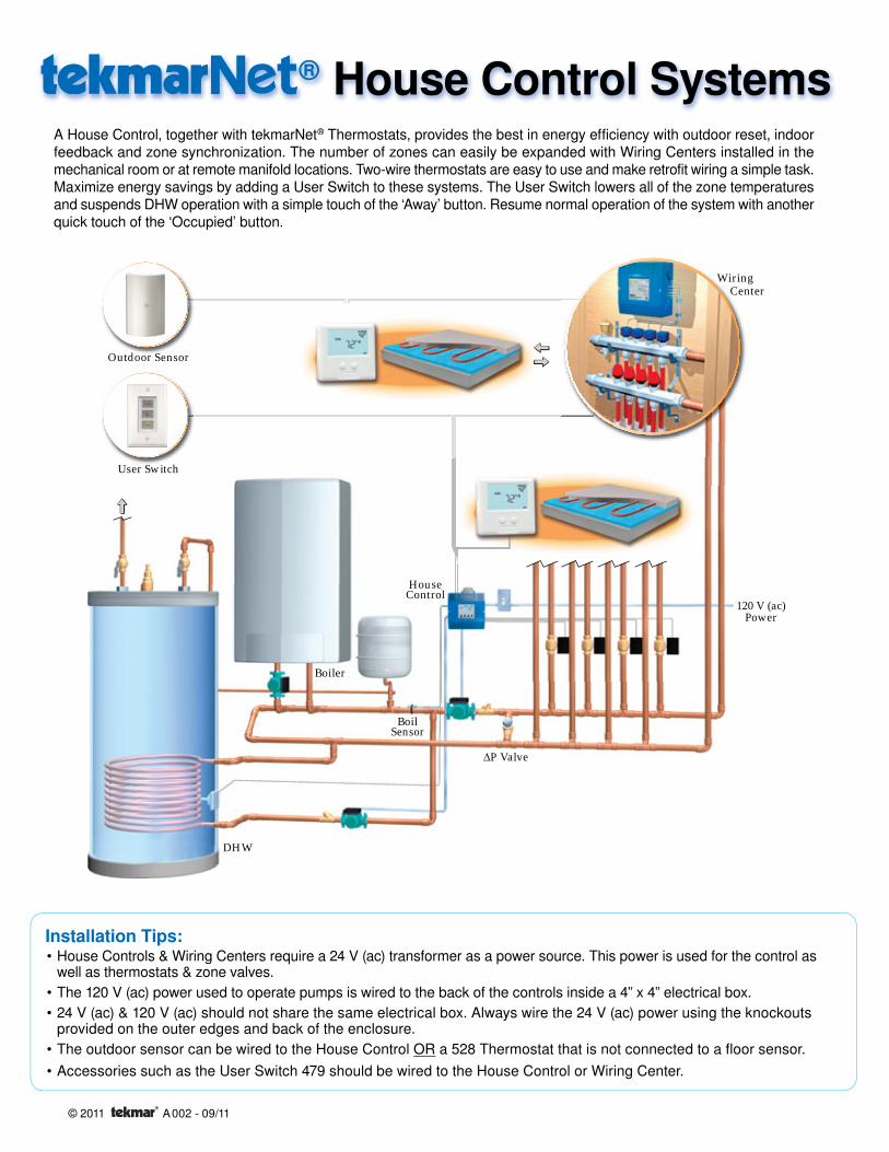
A House Control, together with tekmarNet® Thermostats, provides the best in energy efficiency with outdoor reset, indoor feedback and zone synchronization. The number of zones can easily be expanded with Wiring Centers installed in the mechanical room or at remote manifold locations. Two-wire thermostats are easy to use and make retrofit wiring a simple task. Maximize energy savings by adding a User Switch to these systems. The User Switch lowers all of the zone temperatures and suspends DHW operation with a simple touch of the ‘Away’ button. Resume normal operation of the system with another quick touch of the ‘Occupied’ button.
Installation Tips:House Controls & Wiring Centers require a 24 V (ac) transformer as a power source. This power is used for the control as well as thermostats & zone valves.The 120 V (ac) power used to operate pumps is wired to the back of the controls inside a 4” x 4” electrical box.24 V (ac) & 120 V (ac) should not share the same electrical box. Always wire the 24 V (ac) power using the knockouts provided on the outer edges and back of the enclosure.The outdoor sensor can be wired to the House Control OR a 528 Thermostat that is not connected to a floor sensor.Accessories such as the User Switch 479 should be wired to the House Control or Wiring Center.
•
••
••
House Control
WiringCenter
Outdoor Sensor
User Switch
BoilSensor
ΔP Valve
Boiler
DHW
120 V (ac)Power
® House Control Systems
1 of 32 © 2011 A 002 - 10/11
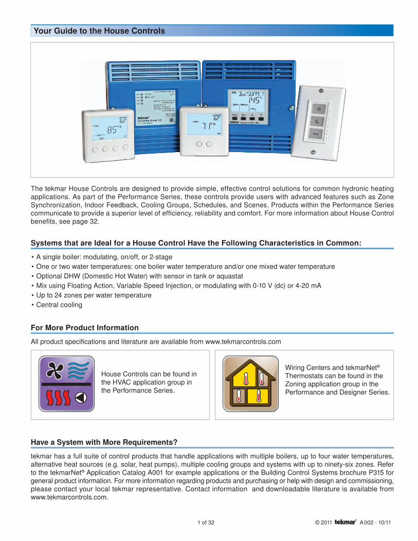
The tekmar House Controls are designed to provide simple, effective control solutions for common hydronic heating applications. As part of the Performance Series, these controls provide users with advanced features such as Zone Synchronization, Indoor Feedback, Cooling Groups, Schedules, and Scenes. Products within the Performance Series communicate to provide a superior level of efficiency, reliability and comfort. For more information about House Control benefits, see page 32.
Have a System with More Requirements?
tekmar has a full suite of control products that handle applications with multiple boilers, up to four water temperatures, alternative heat sources (e.g. solar, heat pumps), multiple cooling groups and systems with up to ninety-six zones. Refer to the tekmarNet® Application Catalog A001 for example applications or the Building Control Systems brochure P315 for general product information. For more information regarding products and purchasing or help with design and commissioning, please contact your local tekmar representative. Contact information and downloadable literature is available from www.tekmarcontrols.com.
Your Guide to the House Controls
Systems that are Ideal for a House Control Have the Following Characteristics in Common:
A single boiler: modulating, on/off, or 2-stageOne or two water temperatures: one boiler water temperature and/or one mixed water temperatureOptional DHW (Domestic Hot Water) with sensor in tank or aquastatMix using Floating Action, Variable Speed Injection, or modulating with 0-10 V (dc) or 4-20 mAUp to 24 zones per water temperatureCentral cooling
••••••
House Controls can be found in the HVAC application group in the Performance Series.
Wiring Centers and tekmarNet® Thermostats can be found in the Zoning application group in the Performance and Designer Series.
For More Product Information
All product specifications and literature are available from www.tekmarcontrols.com

© 2011 A 002 - 10/11 2 of 32
Refer to the chart below to find an application that is the closest match to your system. All example applications have a minimum and maximum number of zones that can be controlled using the equipment shown. To increase the maximum number of zones (up to 24 total per water temperature), connect additional wiring centers to available tN4 expansion terminals.
Step 1 - Find Application
Drawing # Boiler Temperature Zones # Mix Temperature Zones
Mixing Device PageZone Valves Zone Pumps Zone Valves Zone Pumps
A400-1 1 to 4 - - - - 4
A400-2 1 to 8 - - - - 6
A400-3 1 to 4 - - - - 8
A400-4 1 to 4 - - - - 10
A401-1 - 1 to 4 - - - 12
A401-2 - 1 to 8 - - - 14
A402-1 - - 1 to 4 - Variable Speed Injection 16
A402-2 1 to 4 - 1 to 8 - 3-Way Valve 18
A402-3 - - 1 to 4 - 3-Way Valve 20
A402-4 - - 1 to 8 - Variable Speed Injection 22
A403-1 - - - 1 to 4 Variable Speed Injection 24
A403-2 - 1 to 4 - 1 to 8 3-Way Valve 26
Note: For multiple mixed water temperatures or boilers, refer to the A001 brochure on www.tekmarcontrols.com
To Add: Use: Page
Up to four zones with zone valves Wiring Center 313 28
Up to four zones with zone pumps Wiring Center 314 29
Modifying Applications
A tekmarNet® House Control system has the ability to provide an exceptional level of comfort and operational efficiency in any hydronic-heated home. tekmar has designed these controls to optimize specific applications. By choosing one of the applications provided in the following pages, the installer can ensure that the House Control’s capabilities match the mechanical system it is meant to operate.
How to Use This Guide
Boiler, DHW/Setpoint & Boiler System Pump Operation
Boiler Temperature Zones
Mixing Device Mix System Pump with Mix Temperature Zones
Typical parts of a House Control System:
3 of 32 © 2011 A 002 - 10/11
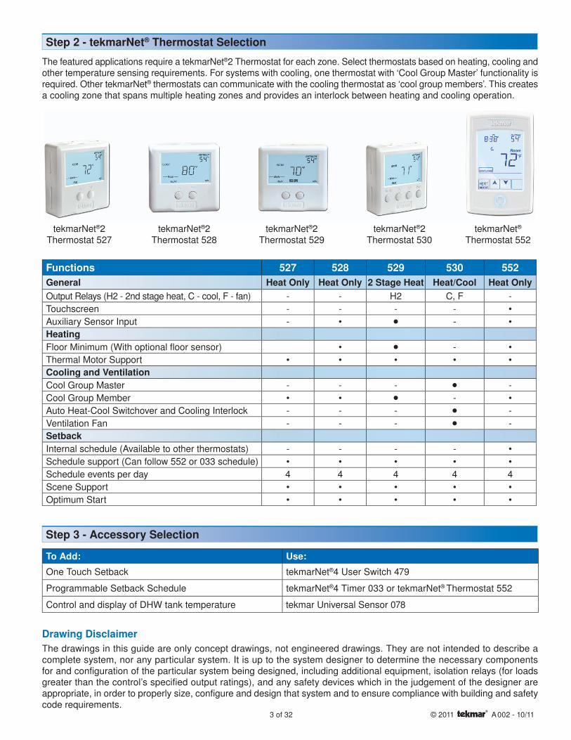
Functions 527 528 529 530 552General Heat Only Heat Only 2 Stage Heat Heat/Cool Heat OnlyOutput Relays (H2 - 2nd stage heat, C - cool, F - fan) - - H2 C, F -Touchscreen - - - - •Auxiliary Sensor Input - • •• - •HeatingFloor Minimum (With optional floor sensor) • •• - •Thermal Motor Support • • • • •Cooling and VentilationCool Group Master - - - •• -Cool Group Member • • •• - •Auto Heat-Cool Switchover and Cooling Interlock - - - •• -Ventilation Fan - - - •• -SetbackInternal schedule (Available to other thermostats) - - - - •Schedule support (Can follow 552 or 033 schedule) • • • • •Schedule events per day 4 4 4 4 4Scene Support • • • • •Optimum Start • • • • •
The featured applications require a tekmarNet®2 Thermostat for each zone. Select thermostats based on heating, cooling and other temperature sensing requirements. For systems with cooling, one thermostat with ‘Cool Group Master’ functionality is required. Other tekmarNet® thermostats can communicate with the cooling thermostat as ‘cool group members’. This creates a cooling zone that spans multiple heating zones and provides an interlock between heating and cooling operation.
Step 2 - tekmarNet® Thermostat Selection
Step 3 - Accessory Selection
To Add: Use:
One Touch Setback tekmarNet®4 User Switch 479
Programmable Setback Schedule tekmarNet®4 Timer 033 or tekmarNet® Thermostat 552
Control and display of DHW tank temperature tekmar Universal Sensor 078
tekmarNet®2 Thermostat 527
tekmarNet®2 Thermostat 528
tekmarNet®2 Thermostat 529
tekmarNet®2 Thermostat 530
tekmarNet® Thermostat 552
The drawings in this guide are only concept drawings, not engineered drawings. They are not intended to describe a complete system, nor any particular system. It is up to the system designer to determine the necessary components for and configuration of the particular system being designed, including additional equipment, isolation relays (for loads greater than the control’s specified output ratings), and any safety devices which in the judgement of the designer are appropriate, in order to properly size, configure and design that system and to ensure compliance with building and safety code requirements.
Drawing Disclaimer

© 2011 A 002 - 10/11 4 of 32
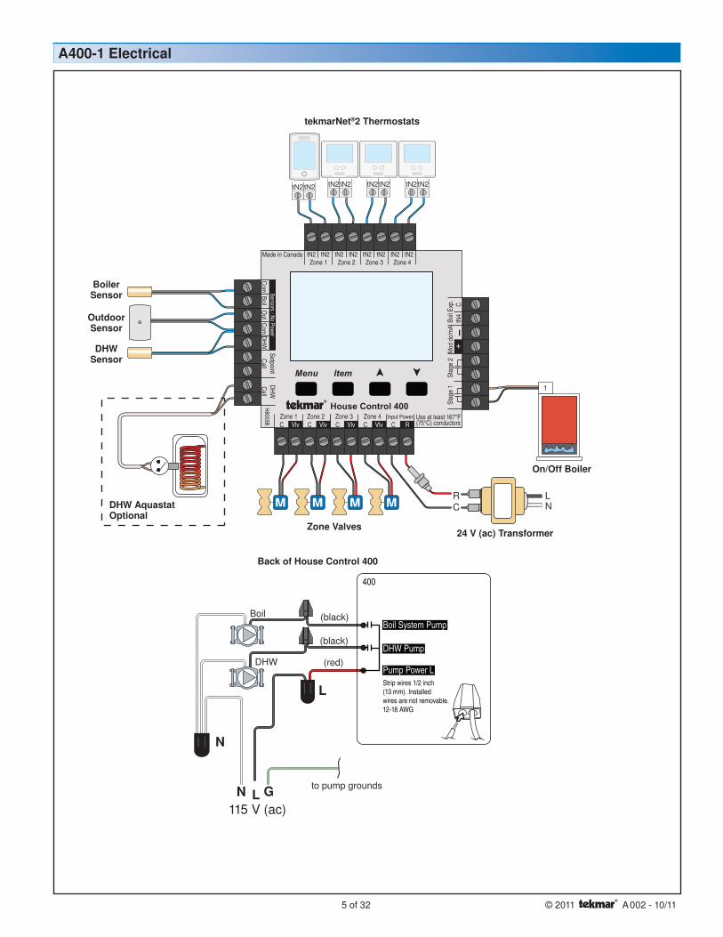
This application is designed for a House Control 400 operating an On/Off boiler with indirect Domestic Hot Water. The four zones shown are operated directly from the 400, but additional zones can be added with a Wiring Center through the tN4 Expansion terminals. tekmarNet®2 Thermostat 527’s provide quality zone temperature control in an easy-to-use two button format. One zone is controlled by a touchscreen tekmarNet® Thermostat 552. The 552 provides a setback schedule that can be followed by all of the thermostats.
Outdoor Design Typical coldest day of yearBoil Type 1 STGBoil Min 140°FDHW Mode 1 (no priority)
2 (priority) Select to give DHW priority over the heating system
A400-1 Mechanical
Product Name Part NumbertN2 House Control 400
3 x Thermostat 5271 x Thermostat 552Transformer Kit 009K
Recommended Applications
Outdoor Sensor
Boiler Sensor
DHW Pump
Boiler System Pump
On/Off Boiler
Zone Valves
tekmarNet®2 Thermostats
Application Settings Suggested Controls
Product Name Part NumberUniversal Sensor (DHW) 078
User Switch 479
Recommended Accessories
DHW Sensor
House Control 400
5 of 32 © 2011 A 002 - 10/11
1
tN2tN2tN2tN2tN2tN2tN2tN2
115 V (ac)LN G to pump grounds
N
L
(red)
(black)
(black)
Menu
House Control 400
Item
+Com
BoilO
utDHW
VlvC VlvC VlvCZone 3Zone 1 Zone 2 Zone 4
VlvC
Com
Zone 1 Zone 2 Zone 3 Zone 4tN2 tN2 tN2 tN2 tN2 tN2 tN2 tN2
Sensors - No PowerCall
CalltN
4C
Mod
dc/
mA
Boil E
xp.
SetpointDHW
RCInput Power
H8005B
Made in Canada
Use at least 167°F(75°C) conductors
Stag
e 2
Stag
e 1
Strip wires 1/2 inch(13 mm). Installedwires are not removable.12-18 AWG
DHW Pump
Pump Power L
400
Boil System Pump
NL
CR
DHW
Boil
Outdoor Sensor
Boiler Sensor
On/Off Boiler
24 V (ac) TransformerZone Valves
tekmarNet®2 Thermostats
A400-1 Electrical
DHW Sensor
DHW AquastatOptional
Back of House Control 400

© 2011 A 002 - 10/11 6 of 32
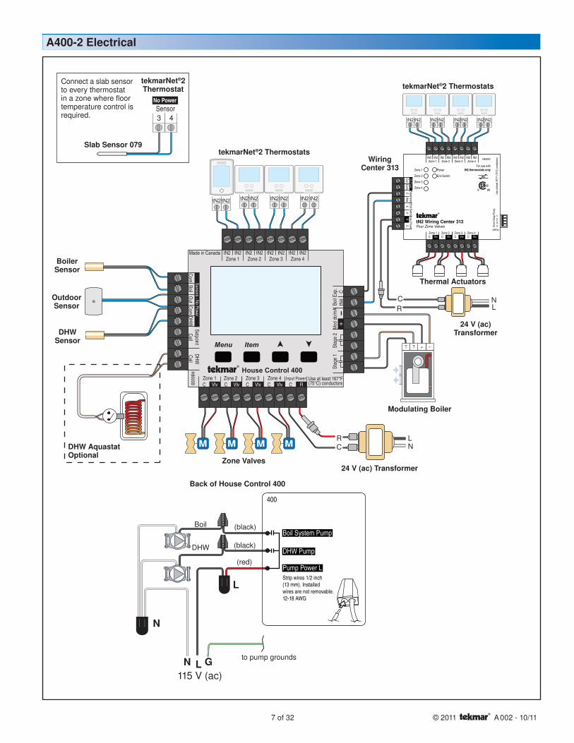
This application is designed for a House Control 400 operating a modulating boiler with indirect Domestic Hot Water. Four of the zones shown are operated directly from the 400, with an additional four zones added through the use of a 313 Wiring Center mounted remotely at the manifold. One 552 and seven 528’s provide control of radiant floors and improve comfort through the use of 079 slab sensors. The 552 provides a setback schedule that can be followed by all of the thermostats. The boiler operates its own circulator to maintain adequate flow.
Outdoor Design Typical coldest day of yearBoil Type 0-10Boil Min OffDHW Mode 1 (no priority)
2 (priority) Select to give DHW priority over the heating system
A400-2 Mechanical
Product Name Part NumbertN2 House Control 400tN2 Wiring Center 313
7 x Thermostat 5281 x Thermostat 5528 x Slab Sensor 079
2 x Transformer Kit 009K
Outdoor Sensor
Boiler Sensor
DHW Pump
Boiler System Pump
Zone Valves
Modulating Boiler
tekmarNet®2 Thermostats tekmarNet®2 Thermostats
Thermal Actuators
Application Settings Suggested Controls
Product Name Part NumberUniversal Sensor (DHW) 078
User Switch 479
Recommended Accessories
DHW Sensor
Zone Group PumpDIP 1 OffDIP 2 OffDIP 3 OffDIP 4 Off
313 Wiring Center DIP Switch Settings
House Control 400
Wiring Center 313
7 of 32 © 2011 A 002 - 10/11
tN2tN2tN2tN2tN2tN2tN2tN2
tN2tN2tN2tN2tN2tN2tN2tN2
NL
CR
+TT -
NL
CR
115 V (ac)LN G
Boil
DHW
to pump grounds
N
L
(red)
(black)
(black)
Menu
House Control 400
Item+
ComBoil
Out
DHWVlvC VlvC VlvC
Zone 3Zone 1 Zone 2 Zone 4VlvC
Com
Zone 1 Zone 2 Zone 3 Zone 4tN2 tN2 tN2 tN2 tN2 tN2 tN2 tN2
Sensors - No PowerCall
Call
tN4
CM
od d
c/m
ABo
il Exp
.
SetpointDHW
RCInput Power
H8005B
Made in Canada
Use at least 167°F(75°C) conductors
Stag
e 2
Stag
e 1
Strip wires 1/2 inch(13 mm). Installedwires are not removable.12-18 AWG
DHW Pump
Pump Power L
400
Boil System Pump
Outdoor Sensor
Boiler Sensor
Modulating Boiler
24 V (ac) TransformerZone Valves
tekmarNet®2 ThermostatsWiring
Center 313
A400-2 Electrical
Thermal Actuators
DHW Sensor
DHW AquastatOptional
24 V (ac) Transformer
tekmarNet®2 Thermostats
Back of House Control 400
No PowerSensor3 4
tekmarNet®2Thermostat
Slab Sensor 079
Connect a slab sensor to every thermostat in a zone where floor temperature control is required.
© 2011 A 002 - 10/11 8 of 32
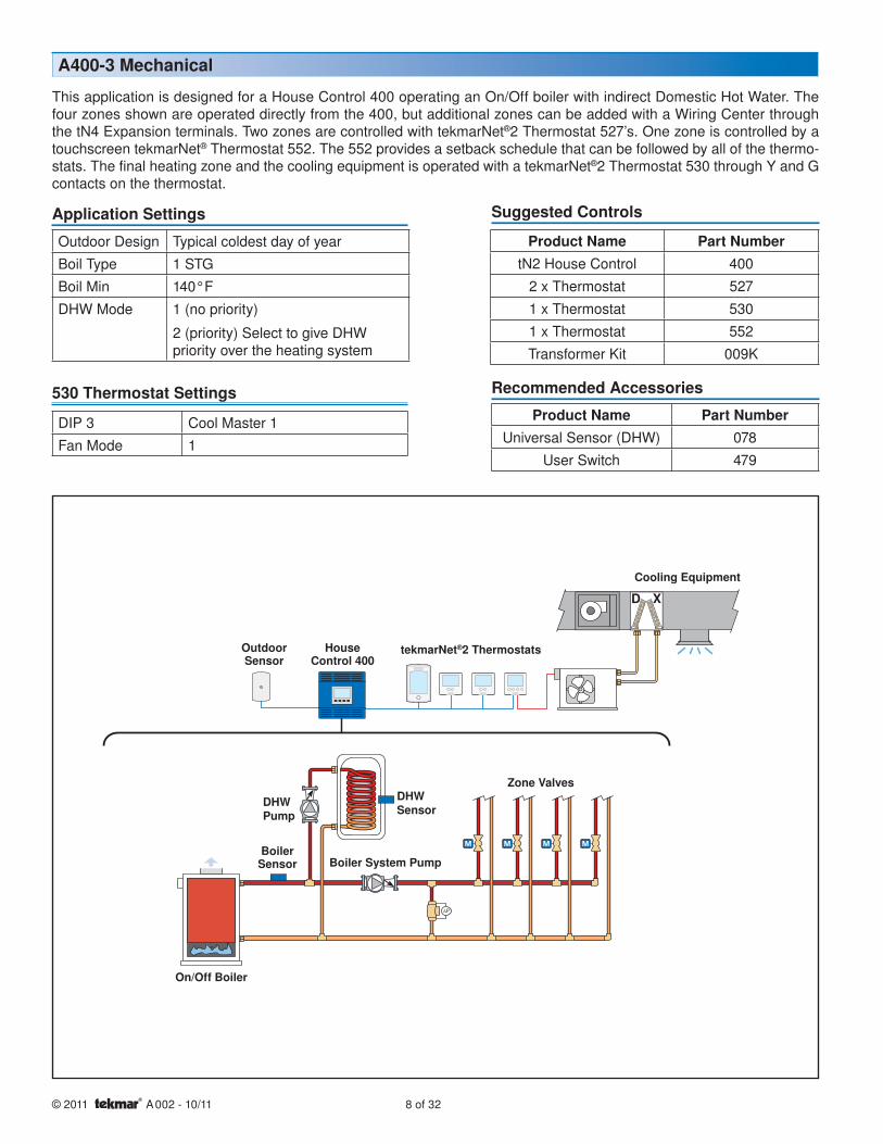
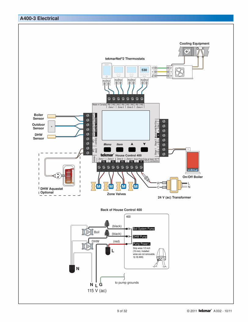
This application is designed for a House Control 400 operating an On/Off boiler with indirect Domestic Hot Water. The four zones shown are operated directly from the 400, but additional zones can be added with a Wiring Center through the tN4 Expansion terminals. Two zones are controlled with tekmarNet®2 Thermostat 527’s. One zone is controlled by a touchscreen tekmarNet® Thermostat 552. The 552 provides a setback schedule that can be followed by all of the thermo-stats. The final heating zone and the cooling equipment is operated with a tekmarNet®2 Thermostat 530 through Y and G contacts on the thermostat.
Outdoor Design Typical coldest day of yearBoil Type 1 STGBoil Min 140°FDHW Mode 1 (no priority)
2 (priority) Select to give DHW priority over the heating system
A400-3 Mechanical
Product Name Part NumbertN2 House Control 400
2 x Thermostat 5271 x Thermostat 5301 x Thermostat 552Transformer Kit 009K
Outdoor Sensor
Boiler Sensor
DHW Pump
Boiler System Pump
Cooling Equipment
Zone Valves
On/Off Boiler
tekmarNet®2 Thermostats
Application Settings Suggested Controls
Product Name Part NumberUniversal Sensor (DHW) 078
User Switch 479
Recommended Accessories
DHW Sensor
House Control 400
DIP 3 Cool Master 1Fan Mode 1
530 Thermostat Settings
9 of 32 © 2011 A 002 - 10/11
NL
CR
1
tN2tN2
115 V (ac)LN G
Boil
DHW
to pump grounds
N
L
(red)
(black)
(black)
Menu
House Control 400
Item
+Com
BoilO
utDHW
VlvC VlvC VlvCZone 3Zone 1 Zone 2 Zone 4
VlvC
Com
Zone 1 Zone 2 Zone 3 Zone 4tN2 tN2 tN2 tN2 tN2 tN2 tN2 tN2
Sensors - No PowerCall
CalltN
4C
Mod
dc/
mA
Boil E
xp.
SetpointDHW
RCInput Power
H8005B
Made in Canada
Use at least 167°F(75°C) conductors
Stag
e 2
Stag
e 1
Strip wires 1/2 inch(13 mm). Installedwires are not removable.12-18 AWG
DHW Pump
Pump Power L
400
Boil System Pump
Rc
YG
GY
RtN2tN2tN2tN2tN2tN2
On/Off Boiler
24 V (ac) TransformerZone Valves
tekmarNet®2 Thermostats
Cooling Equipment
A400-3 Electrical
DHW AquastatOptional
Outdoor Sensor
Boiler Sensor
DHW Sensor
Back of House Control 400
530
© 2011 A 002 - 10/11 10 of 32
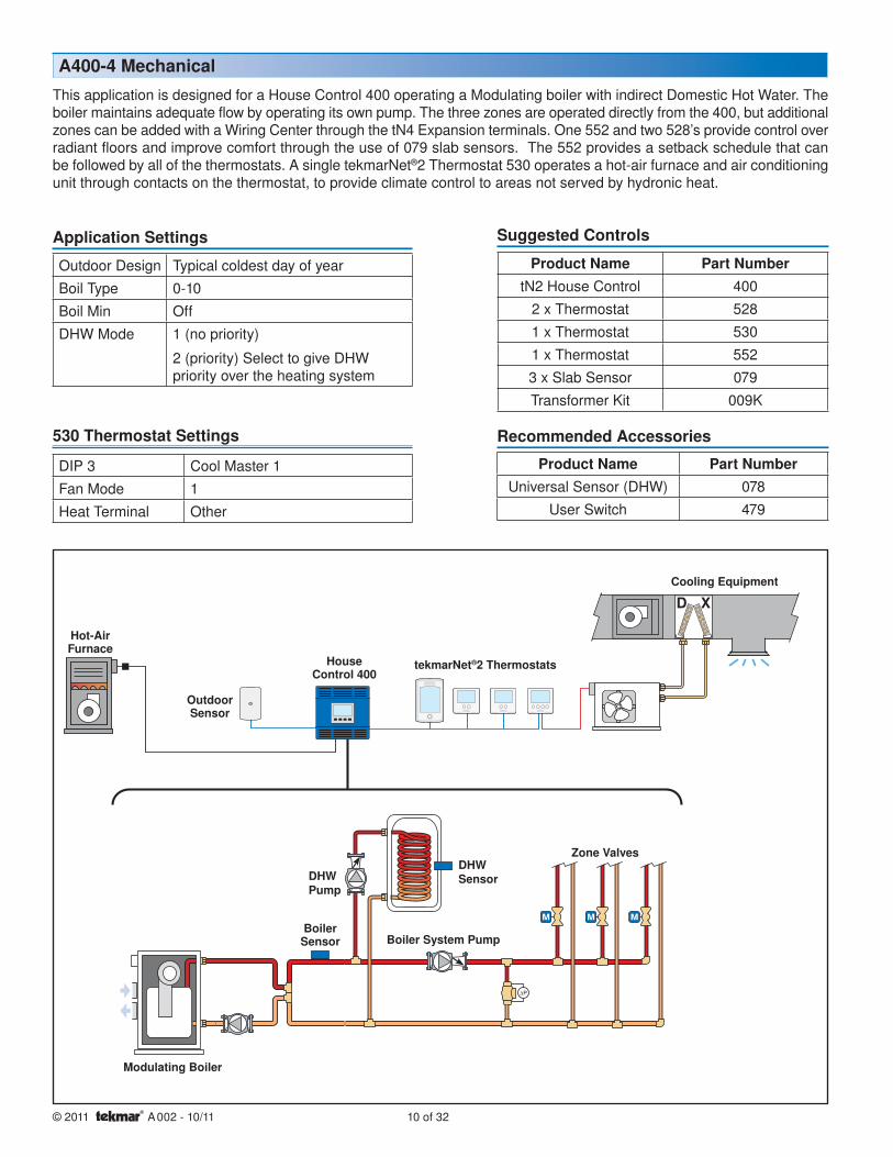
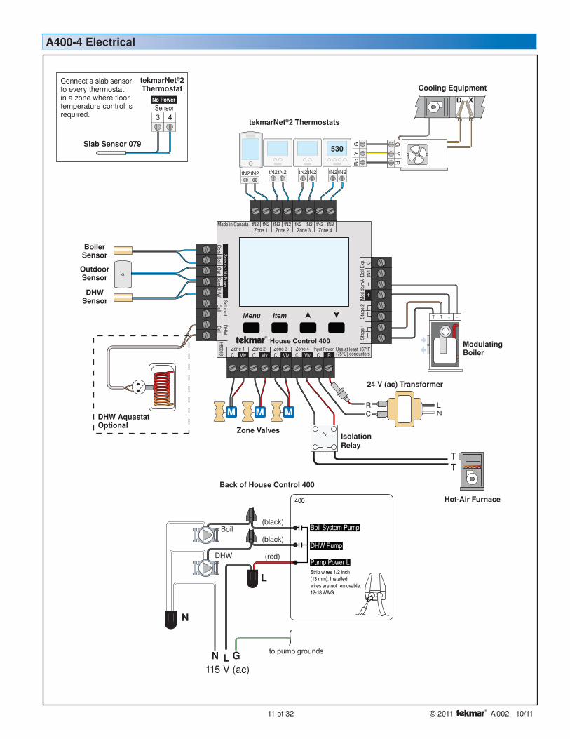
This application is designed for a House Control 400 operating a Modulating boiler with indirect Domestic Hot Water. The boiler maintains adequate flow by operating its own pump. The three zones are operated directly from the 400, but additional zones can be added with a Wiring Center through the tN4 Expansion terminals. One 552 and two 528’s provide control over radiant floors and improve comfort through the use of 079 slab sensors. The 552 provides a setback schedule that can be followed by all of the thermostats. A single tekmarNet®2 Thermostat 530 operates a hot-air furnace and air conditioning unit through contacts on the thermostat, to provide climate control to areas not served by hydronic heat.
Outdoor Design Typical coldest day of yearBoil Type 0-10Boil Min OffDHW Mode 1 (no priority)
2 (priority) Select to give DHW priority over the heating system
A400-4 Mechanical
Application Settings Suggested Controls
Product Name Part NumbertN2 House Control 400
2 x Thermostat 5281 x Thermostat 5301 x Thermostat 5523 x Slab Sensor 079Transformer Kit 009K
Outdoor Sensor
Boiler Sensor
DHW Pump
Boiler System Pump
Hot-Air Furnace
Cooling Equipment
Zone Valves
Modulating Boiler
tekmarNet®2 Thermostats
Product Name Part NumberUniversal Sensor (DHW) 078
User Switch 479
Recommended Accessories
DIP 3 Cool Master 1Fan Mode 1Heat Terminal Other
530 Thermostat Settings
DHW Sensor
House Control 400
11 of 32 © 2011 A 002 - 10/11
+TT -
NL
CR
tN2tN2tN2tN2tN2tN2
Rc
YG
TT
115 V (ac)LN G
Boil
DHW
to pump grounds
N
L
(red)
(black)
(black)
Menu
House Control 400
Item
+
ComBoil
Out
DHWVlvC VlvC VlvC
Zone 3Zone 1 Zone 2 Zone 4VlvC
Com
Zone 1 Zone 2 Zone 3 Zone 4tN2 tN2 tN2 tN2 tN2 tN2 tN2 tN2
Sensors - No PowerCall
Call
tN4
CM
od d
c/mA
Boil E
xp.
SetpointDHW
RCInput Power
H8005B
Made in Canada
Use at least 167°F(75°C) conductors
Stag
e 2
Stag
e 1
Strip wires 1/2 inch(13 mm). Installedwires are not removable.12-18 AWG
DHW Pump
Pump Power L
400
Boil System Pump
GY
RtN2tN2
Modulating Boiler
24 V (ac) Transformer
Zone Valves
tekmarNet®2 Thermostats
Hot-Air Furnace
A400-4 Electrical
Cooling Equipment
Isolation Relay
DHW AquastatOptional
Outdoor Sensor
Boiler Sensor
DHW Sensor
Back of House Control 400
530
No PowerSensor3 4
tekmarNet®2Thermostat
Slab Sensor 079
Connect a slab sensor to every thermostat in a zone where floor temperature control is required.
© 2011 A 002 - 10/11 12 of 32
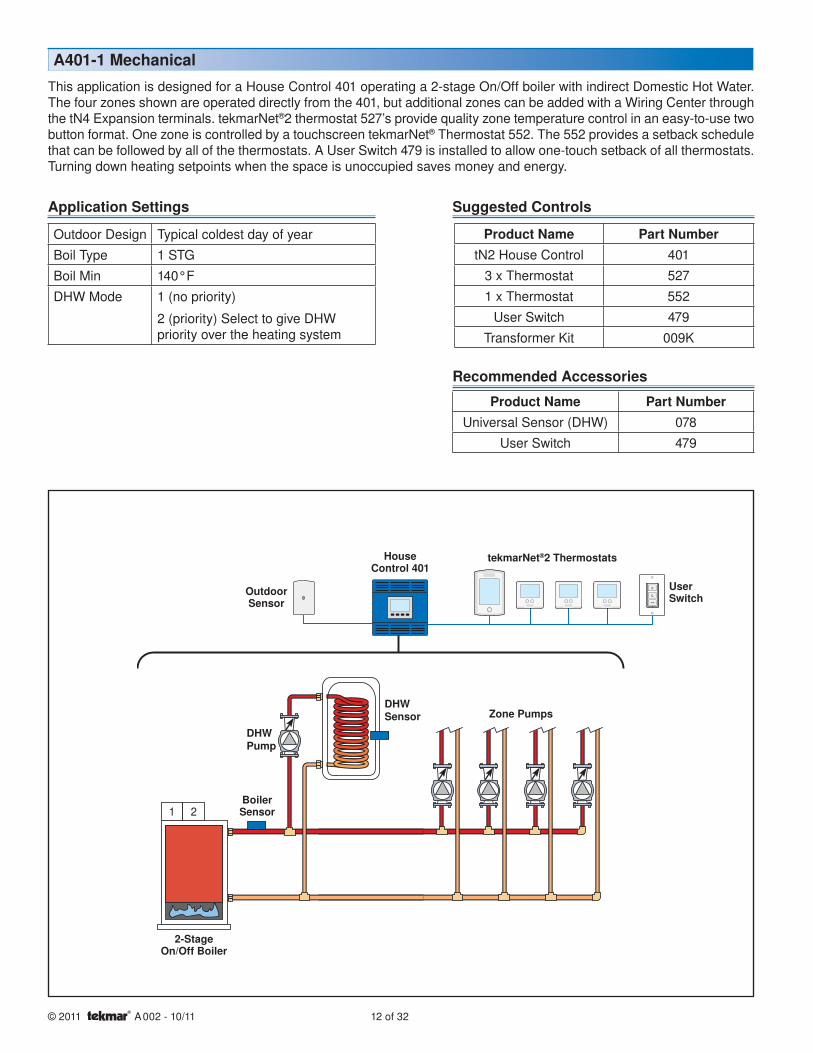
This application is designed for a House Control 401 operating a 2-stage On/Off boiler with indirect Domestic Hot Water. The four zones shown are operated directly from the 401, but additional zones can be added with a Wiring Center through the tN4 Expansion terminals. tekmarNet®2 thermostat 527’s provide quality zone temperature control in an easy-to-use two button format. One zone is controlled by a touchscreen tekmarNet® Thermostat 552. The 552 provides a setback schedule that can be followed by all of the thermostats. A User Switch 479 is installed to allow one-touch setback of all thermostats. Turning down heating setpoints when the space is unoccupied saves money and energy.
1 2
Outdoor Design Typical coldest day of yearBoil Type 1 STGBoil Min 140°FDHW Mode 1 (no priority)
2 (priority) Select to give DHW priority over the heating system
A401-1 Mechanical
Product Name Part NumbertN2 House Control 401
3 x Thermostat 5271 x Thermostat 552
User Switch 479Transformer Kit 009K
Outdoor Sensor
Boiler Sensor
DHW Pump
2-StageOn/Off Boiler
Zone Pumps
tekmarNet®2 Thermostats
Application Settings Suggested Controls
Product Name Part NumberUniversal Sensor (DHW) 078
User Switch 479
Recommended Accessories
DHW Sensor
User Switch
House Control 401

13 of 32 © 2011 A 002 - 10/11
NL
CR
tN4 C R
tN2tN2tN2tN2tN2tN2tN2tN2
Menu
House Control 401
Item
+Com
BoilO
utDHW
Com
Zone 1
H8006B
Zone 2 Zone 3 Zone 4tN2 tN2 tN2 tN2 tN2 tN2 tN2 tN2
Sensors - No PowerCall
Call
tN4
CM
od d
c/mA
Boil E
xp.
SetpointDHW
RCInput Power
Made in Canada
Use at least 167°F(75°C) conductors
Stag
e 2
Stag
e 1
115 V (ac)NG L
NL(red)
(black)
(black)
(black)
(black)
(black)
DHW
Zone 4
Zone 3
Zone 2
Zone 1
to pumpgrounds
Back ofHouse Control 401
401
Zone 4 Zone 3
Zone 2
Zone 1DHW Pump
Pump Power
Strip wires 1/2 inch(13 mm). Installedwires are not removable.12-18 AWG
1 2
2-StageOn/Off Boiler
24 V (ac) Transformer
tekmarNet®2 Thermostats
A401-1 Electrical
User Switch
DHW AquastatOptional
Outdoor Sensor
Boiler Sensor
DHW Sensor

© 2011 A 002 - 10/11 14 of 32
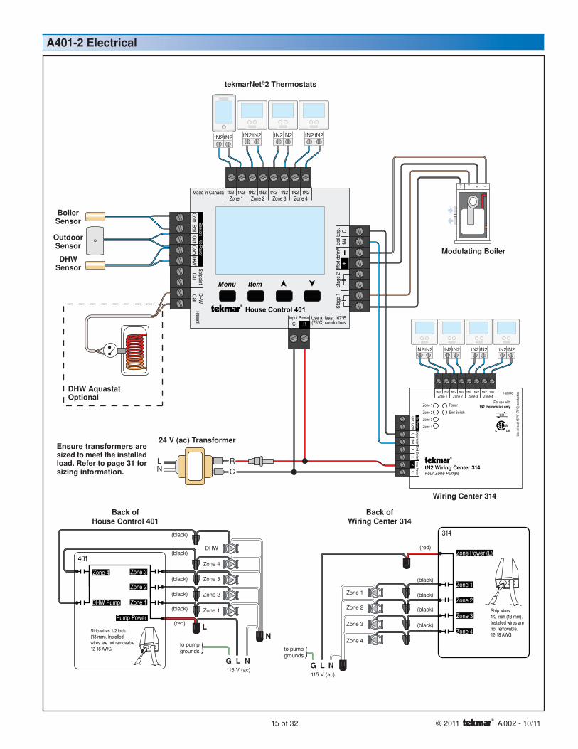
This application is designed for a House Control 401 operating a Modulating boiler with indirect Domestic Hot Water. Four of the zones shown are operated directly from the 401, and an additional four zones are operated by a Wiring Center 314 connected to the tN4 Expansion terminals. tekmarNet®2 thermostat 527’s provide quality zone temperature control in an easy-to-use two button format. One zone is controlled by a touchscreen tekmarNet® Thermostat 552. The 552 provides a setback schedule that can be followed by all of the thermostats. The boiler operates its own circulator to maintain adequate flow.
Outdoor Design Typical coldest day of yearBoil Type 0-10Boil Min OffDHW Mode 1 (no priority)
2 (priority) Select to give DHW priority over the heating system
A401-2 Mechanical
Product Name Part NumbertN2 House Control 401tN2 Wiring Center 314
7 x Thermostat 5271 x Thermostat 552Transformer Kit 009K
Boiler Sensor
DHW Pump
Modulating Boiler
Zone Pumps
Application Settings Suggested Controls
Product Name Part NumberUniversal Sensor (DHW) 078
User Switch 479
Recommended Accessories
DHW Sensor
Outdoor Sensor tekmarNet®2 Thermostats
House Control 401
Wiring Center 314tekmarNet®2 Thermostats
15 of 32 © 2011 A 002 - 10/11
tN2tN2tN2tN2tN2tN2tN2tN2
NL
CR
tN2tN2tN2tN2tN2tN2tN2tN2
Menu
House Control 401
Item
+
ComBoil
Out
DHWCom
Zone 1
H8006B
Zone 2 Zone 3 Zone 4tN2 tN2 tN2 tN2 tN2 tN2 tN2 tN2
Sensors - No PowerCall
Call
tN4
CM
od d
c/m
ABo
il Exp
.
SetpointDHW
RCInput Power
Made in Canada
Use at least 167°F(75°C) conductors
Stag
e 2
Stag
e 1
PowerZone 1
Zone 2
Zone 3
Zone 4
End Switch
Zone 1 Zone 2 Zone 3 Zone 4tN2 tN2 tN2 tN2 tN2 tN2 tN2 tN2
tN2 Wiring Center 314Four Zone Pumps
tN4C
XExpansion
XC
Input PowerR
H8004C
End Switch
For use withtN2 thermostats only
tN2
Use
at le
ast 1
67°F
(75°
C) c
ondu
ctor
s
ComO
utNo Power
115 V (ac)NG L
NL(red)
(black)
(black)
(black)
(black)
(black)
DHW
Zone 4
Zone 3
Zone 2
Zone 1
to pumpgrounds
Back ofHouse Control 401
Back ofWiring Center 314
24 V (ac) Transformer
401
Zone 4 Zone 3
Zone 2
Zone 1DHW Pump
Pump Power
Strip wires 1/2 inch(13 mm). Installedwires are not removable.12-18 AWG
115 V (ac)L NG
(red)
(black)
(black)
(black)
(black)
to pumpgrounds
Zone 2
Zone 3
Zone 4
Zone 1
Zone Power (L)
Zone 1
Zone 2
Zone 3
Zone 4
Strip wires1/2 inch (13 mm).Installed wires arenot removable.12-18 AWG
314
+TT -
Modulating Boiler
tekmarNet®2 Thermostats
A401-2 Electrical
Wiring Center 314
DHW AquastatOptional
Outdoor Sensor
Boiler Sensor
DHW Sensor
Ensure transformers are sized to meet the installed load. Refer to page 31 for sizing information.

© 2011 A 002 - 10/11 16 of 32
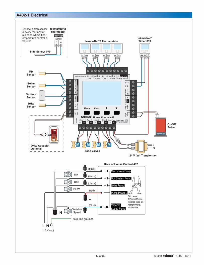
This application is designed for a House Control 402 operating an On/Off boiler with indirect Domestic Hot Water. Mixing is performed with variable speed injection, which supplies an outdoor reset water temperature to four mix temperature hydronic zones. The four zones shown are operated directly from the 402, but additional zones can be added with a Wiring Center through the tN4 Expansion terminals. Four tekmarNet®2 thermostat 528’s provide control over radiant floors and improve comfort through the use of 079 slab sensors. A tekmar Timer 033 provides multiple scheduling options in order to setback the temperature in the zones saving money and energy.
Outdoor Design Typical coldest day of yearMix Type VARBoil Type 1 STGBoil Min 140°FDHW Mode 1 (no priority)
2 (priority) Select to give DHW priority over the heating system
A402-1 Mechanical
Product Name Part NumbertN2 House Control 402
4 x Thermostat 5284 x Slab Sensor 079
tN4 Timer 033Transformer Kit 009K
Outdoor Sensor
Mix Sensor
Boiler Sensor
On/Off Boiler
Zone Valves
tekmarNet®2 ThermostatstekmarNet® Timer 033
Boiler System Pump
Mix System Pump
Variable Speed Pump
DHW Pump
Application Settings Suggested Controls
Product Name Part NumberUniversal Sensor (DHW) 078
User Switch 479
Recommended Accessories
DHW Sensor
House Control 402
17 of 32 © 2011 A 002 - 10/11
tN2tN2tN2tN2tN2tN2tN2tN2 tN4 C R
NL
CR
1
Mix
Boil
DHW
Variable Speed
115 V (ac)NL G
to pump grounds
N
L
Back of House Control 402
Strip wires1/2 inch (13 mm).Installed wires arenot removable.12-18 AWG
(blue)
(red)
(black)
(black)
(black)
Menu
House Control 402
Item
+M
ixCom
BoilO
utDHW
VlvC VlvC VlvCZone 3Zone 1 Zone 2 Zone 4
Made in Canada
VlvC
Com
Zone 1
H8007B
Zone 2 Zone 3 Zone 4tN2 tN2 tN2 tN2 tN2 tN2 tN2 tN2 C
Floating ActionClsOpn
Sensors - No PowerCall
CalltN
4tN
4C
CM
od d
c/m
ABo
il Exp
.M
ix Ex
p.Setpoint
DHW
Use at least 167°F(75°C) conductorsRC
Input Power
Stag
e 2
Stag
e 1
Boil System Pump
Mix System Pump
DHW Pump
VariableSpeed Pump
Pump Power L
Mix Sensor
On/Off Boiler
24 V (ac) Transformer
Zone Valves
tekmarNet®2 Thermostats
A402-1 Electrical
tekmarNet® Timer 033
DHW AquastatOptional
Outdoor Sensor
Boiler Sensor
DHW Sensor
No PowerSensor3 4
tekmarNet®2Thermostat
Slab Sensor 079
Connect a slab sensor to every thermostat in a zone where floor temperature control is required.

© 2011 A 002 - 10/11 18 of 32
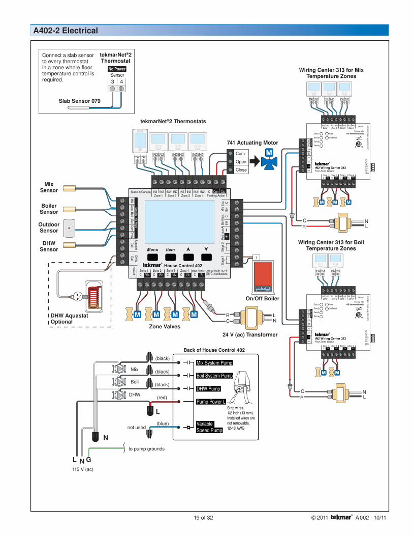
This application is designed for a House Control 402 operating an On/Off boiler with indirect Domestic Hot Water. Mixing is performed with a three-way floating action mixing valve, which supplies an outdoor reset water temperature to seven mix temperature hydronic zones. Four mix temperature zones shown are operated directly from the 402, an additional three mix zones are operated with a Wiring Center 313 connected through the tN4 Mix Expansion terminals. Two boiler temperature zones are operated with a second Wiring Center 313 connected to the tN4 Boiler Expansion terminals. One 552 and six 528’s operate low temperature radiant floors maintaining superior comfort through the use of 079 slab sensors. The 552 provides a setback schedule that can be followed by all of the thermostats. Two high temperature baseboard zones are operated with tekmarNet®2 thermostat 527’s.
Outdoor Design Typical coldest day of yearMix Type FLOTBoil Type 1 STGBoil Min 140°FDHW Mode 1 (no priority)
2 (priority) Select to give DHW priority over the heating system
A402-2 Mechanical
Product Name Part NumbertN2 House Control 402
2 x tN2 Wiring Center 3132 x Thermostat 5276 x Thermostat 5281 x Thermostat 5527 x Slab Sensor 079
3 x Transformer Kit 009K1 x Actuator 741
1 x Three Way Valve 710 - 714
Outdoor Sensor
Mix Sensor
Boiler Sensor
On/Off Boiler
Zone Valves
Boiler System Pump
Mix System Pump
Three-way Valve
DHW Pump
tekmarNet®2 Thermostats
Application Settings Suggested Controls
Product Name Part NumberUniversal Sensor (DHW) 078
User Switch 479
Recommended AccessoriesZone Group PumpDIP 1 OffDIP 2 OffDIP 3 OffDIP 4 Off
2 x 313 Wiring Center DIP Switch Settings
DHW Sensor
tekmarNet®2 Thermostats
tekmarNet®2 Thermostats
Wiring Center 313
Wiring Center 313
House Control 402
19 of 32 © 2011 A 002 - 10/11
tN2tN2tN2tN2
tN2tN2tN2tN2tN2tN2
NL
CR
tN2tN2tN2tN2tN2tN2tN2tN2
1
NL
CR
NL
CR
Mix
Boil
DHW
not used
115 V (ac)NL G
to pump grounds
N
L
Back of House Control 402
Strip wires1/2 inch (13 mm).Installed wires arenot removable.12-18 AWG
(blue)
(red)
(black)
(black)
(black)
Menu
House Control 402
Item
+
Mix
ComBoil
Out
DHW
VlvC VlvC VlvCZone 3Zone 1 Zone 2 Zone 4
Made in Canada
VlvC
Com
Zone 1
H8007B
Zone 2 Zone 3 Zone 4tN2 tN2 tN2 tN2 tN2 tN2 tN2 tN2 C
Floating ActionClsOpn
Sensors - No PowerCall
Call
tN4
tN4
CC
Mod
dc/
mA
Boil E
xp.
Mix
Exp.
SetpointDHW
Use at least 167°F(75°C) conductorsRC
Input Power
Stag
e 2
Stag
e 1
Boil System Pump
Mix System Pump
DHW Pump
VariableSpeed Pump
Pump Power L
Com
Open
Close
On/Off Boiler
24 V (ac) Transformer
A402-2 Electrical
tekmarNet®2 Thermostats
Wiring Center 313 for Mix Temperature Zones
Wiring Center 313 for Boil Temperature Zones
741 Actuating Motor
Zone Valves
DHW AquastatOptional
Mix Sensor
Outdoor Sensor
Boiler Sensor
DHW Sensor
No PowerSensor3 4
tekmarNet®2Thermostat
Slab Sensor 079
Connect a slab sensor to every thermostat in a zone where floor temperature control is required.
© 2011 A 002 - 10/11 20 of 32
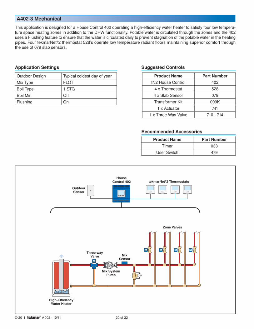
This application is designed for a House Control 402 operating a high-efficiency water heater to satisfy four low tempera-ture space heating zones in addition to the DHW functionality. Potable water is circulated through the zones and the 402 uses a Flushing feature to ensure that the water is circulated daily to prevent stagnation of the potable water in the heating pipes. Four tekmarNet®2 thermostat 528’s operate low temperature radiant floors maintaining superior comfort through the use of 079 slab sensors.
Outdoor Design Typical coldest day of yearMix Type FLOTBoil Type 1 STGBoil Min OffFlushing On
A402-3 Mechanical
Product Name Part NumbertN2 House Control 402
4 x Thermostat 5284 x Slab Sensor 079Transformer Kit 009K
1 x Actuator 7411 x Three Way Valve 710 - 714
Mix Sensor
High-Efficiency Water Heater
Zone Valves
Mix System Pump
Three-way Valve
tekmarNet®2 Thermostats
Outdoor Sensor
Application Settings Suggested Controls
Product Name Part NumberTimer 033
User Switch 479
Recommended Accessories
House Control 402

21 of 32 © 2011 A 002 - 10/11
tN2tN2tN2tN2tN2tN2tN2tN2
NL
CR
Mix
115 V (ac)NL G
to pump grounds
N
L
Back of House Control 402
Strip wires1/2 inch (13 mm).Installed wires arenot removable.12-18 AWG
(blue)
(red)
(black)
(black)
(black)
Menu
House Control 402
Item
+M
ixCom
BoilO
utDHW
VlvC VlvC VlvCZone 3Zone 1 Zone 2 Zone 4
Made in Canada
VlvC
Com
Zone 1
H8007B
Zone 2 Zone 3 Zone 4tN2 tN2 tN2 tN2 tN2 tN2 tN2 tN2 C
Floating ActionClsOpn
Sensors - No PowerCall
Call
tN4
tN4
CC
Mod
dc/
mA
Boil E
xp.
Mix
Exp.
SetpointDHW
Use at least 167°F(75°C) conductorsRC
Input Power
Stag
e 2
Stag
e 1
Boil System Pump
Mix System Pump
DHW Pump
VariableSpeed Pump
Pump Power L
Com
Open
Close
Outdoor Sensor
Mix Sensor
24 V (ac) TransformerZone Valves
tekmarNet®2 Thermostats
A402-3 Electrical
741 Actuating Motor
No PowerSensor3 4
tekmarNet®2Thermostat
Slab Sensor 079
Connect a slab sensor to every thermostat in a zone where floor temperature control is required.

© 2011 A 002 - 10/11 22 of 32
This application is designed for a House Control 402 operating an On/Off boiler with indirect Domestic Hot Water. Mixing is performed with a variable speed injection pump, which supplies an outdoor reset water temperature to eight mix temperature hydronic zones. Four mix temperature zones shown are operated directly from the 402, an additional four mix zones are operated with a Wiring Center 313 connected through the tN4 Mix Expansion terminals. Each remote manifold has a pump that is either operated by the Zone Group Pump output on the 313 or the Mix System Pump output on the 402. One 522 and seven 528’s operate low temperature radiant floors maintaining superior comfort through the use of 079 slab sensors. The 552 provides a setback schedule that can be followed by all of the thermostats.
Outdoor Design Typical coldest day of yearMix Type VARBoil Type 1 STGBoil Min 140°FDHW Mode 1 (no priority)
2 (priority) Select to give DHW priority over the heating system
A402-4 Mechanical
Mix Sensor
On/Off Boiler
Remote Manifold
Boil System Pump
Variable Speed Pump
tekmarNet®2 Thermostats
Outdoor Sensor
402 Application Settings Product Name Part NumbertN2 House Control 402tN2 Wiring Center 313
7 x Thermostat 5281 x Thermostat 5528 x Slab Sensor 079
2 x Transformer Kit 009K
Suggested Controls
Product Name Part NumberUniversal Sensor (DHW) 078
User Switch 479
Recommended Accessories
tekmarNet®2 Thermostats
Remote Manifold
DHW Pump
Boiler Sensor
DHW Sensor
Mix System Pump
Zone Group Pump
On 402 Heating Supply Pump OnOn 313 Heating Supply Pump Off
528 Thermostat Settings
Zone Group PumpDIP 1 OnDIP 2 OnDIP 3 OnDIP 4 On
313 Wiring Center DIP Switch Settings
House Control 402
Wiring Center 313

23 of 32 © 2011 A 002 - 10/11
tN2tN2tN2tN2tN2tN2tN2tN2
NL
CR
NL
CR
tN2tN2tN2tN2tN2tN2tN2tN2
MixZone
Group
Boil
DHW
Variable Speed
115 V (ac)NL G
to pump grounds
N
L
Back of House Control 402 Back of Wiring Center 313
Strip wires1/2 inch (13 mm).Installed wires arenot removable.12-18 AWG
(blue)
(red)
(black)
(black)
(black)
Menu
House Control 402
Item
+
Mix
ComBoil
Out
DHW
VlvC VlvC VlvCZone 3Zone 1 Zone 2 Zone 4
Made in Canada
VlvC
Com
Zone 1
H8007B
Zone 2 Zone 3 Zone 4tN2 tN2 tN2 tN2 tN2 tN2 tN2 tN2 C
Floating ActionClsOpn
Sensors - No PowerCall
Call
tN4
tN4
CC
Mod
dc/
mA
Boil E
xp.
Mix
Exp.
SetpointDHW
Use at least 167°F(75°C) conductorsRC
Input Power
Stag
e 2
Stag
e 1
Boil System Pump
Mix System Pump
DHW Pump
VariableSpeed Pump
Pump Power L
115 V (ac)LN G
to pump grounds
N L
(red)
(black)313
Power L
Zone Group Pump
1
Outdoor Sensor
Mix Sensor
24 V (ac) Transformer
Zone Actuators
tekmarNet®2 Thermostats
A402-4 Electrical
Boiler Sensor
DHW AquastatOptional
Zone Actuators
Wiring Center 313
24 V (ac) Transformer
tekmarNet®2 Thermostats
On/OffBoiler
DHWSensor
No PowerSensor3 4
tekmarNet®2Thermostat
Slab Sensor 079
Connect a slab sensor to every thermostat in a zone where floor temperature control is required.

© 2011 A 002 - 10/11 24 of 32
This application is designed for a House Control 403 operating an On/Off boiler with indirect Domestic Hot Water. Mixing is performed with a variable speed injection pump which supplies an outdoor reset water temperature to four mix temperature hydronic zone pumps. Three tekmarNet®2 thermostat 528’s operate low temperature radiant floors maintaining superior comfort through the use of 079 slab sensors. One zone is controlled by a touchscreen tekmarNet® Thermostat 552. The 552 provides a setback schedule that can be followed by all of the thermostats.
Outdoor Design Typical coldest day of yearMix Type VARBoil Type 1 STGBoil Min 140°FDHW Mode 1 (no priority)
2 (priority) Select to give DHW priority over the heating system
A403-1 Mechanical
Product Name Part NumbertN2 House Control 403
3 x Thermostat 5281 x Thermostat 5524 x Slab Sensor 079Transformer Kit 009K
Outdoor Sensor
Mix SensorBoiler Sensor
On/Off Boiler
Zone Pumps
Variable Speed Pump
DHW Pump
tekmarNet®2 Thermostats
Application Settings Suggested Controls
Product Name Part NumberUniversal Sensor (DHW) 078
User Switch 479
Recommended Accessories
Boiler System Pump
DHW Sensor
House Control 403

25 of 32 © 2011 A 002 - 10/11
tN2tN2tN2tN2tN2tN2tN2tN2
1
NL
CR
115 V (ac)N1L1 G
115 V (ac)N2G L2
to pump grounds to pump grounds
N N
L L
Back of House Control 403
Boil Sys Pmp
DHW Pump
VariableSpeed Pump
PumpPower
Zone 4 Zone 3
Zone 2
Zone 1
Zone Power
(blue)
(red)
(black)
(black)Boil
DHW
VariableSpeed
(red)
(black)
(black)
(black)
(black) Zone 4
Zone 3
Zone 2
Zone 1
Menu
House Control 403
Item
+M
ixCom
BoilO
utDHW
Com
Zone 1
H8008A
Zone 2 Zone 3 Zone 4tN2 tN2 tN2 tN2 tN2 tN2 tN2 tN2 C
Floating ActionClsOpn
Sensors - No PowerCall
CalltN
4tN
4C
CM
od d
c/m
ABo
il Exp
.M
ix Ex
p.Setpoint
DHW
RCInput Power
Made in Canada
Use at least 167°F(75°C) conductors
Stag
e 2
Stag
e 1
Outdoor Sensor
Mix Sensor
Boiler Sensor
On/Off Boiler
A403-1 Electrical
24 V (ac) Transformer
DHW Sensor
DHW AquastatOptional
tekmarNet®2 ThermostatsNo PowerSensor3 4
tekmarNet®2Thermostat
Slab Sensor 079
Connect a slab sensor to every thermostat in a zone where floor temperature control is required.
© 2011 A 002 - 10/11 26 of 32
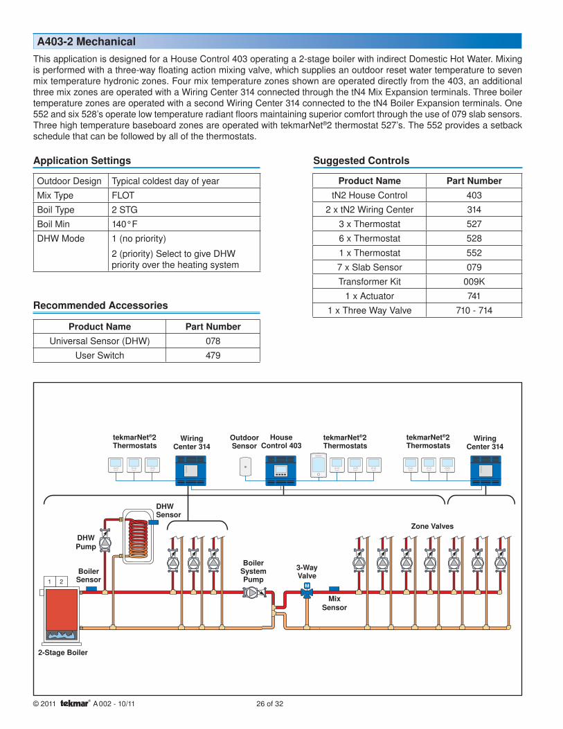
This application is designed for a House Control 403 operating a 2-stage boiler with indirect Domestic Hot Water. Mixing is performed with a three-way floating action mixing valve, which supplies an outdoor reset water temperature to seven mix temperature hydronic zones. Four mix temperature zones shown are operated directly from the 403, an additional three mix zones are operated with a Wiring Center 314 connected through the tN4 Mix Expansion terminals. Three boiler temperature zones are operated with a second Wiring Center 314 connected to the tN4 Boiler Expansion terminals. One 552 and six 528’s operate low temperature radiant floors maintaining superior comfort through the use of 079 slab sensors. Three high temperature baseboard zones are operated with tekmarNet®2 thermostat 527’s. The 552 provides a setback schedule that can be followed by all of the thermostats.
1 2
Outdoor Design Typical coldest day of yearMix Type FLOTBoil Type 2 STGBoil Min 140°FDHW Mode 1 (no priority)
2 (priority) Select to give DHW priority over the heating system
A403-2 Mechanical
Product Name Part NumbertN2 House Control 403
2 x tN2 Wiring Center 3143 x Thermostat 5276 x Thermostat 528
1 x Thermostat 5527 x Slab Sensor 079Transformer Kit 009K
1 x Actuator 7411 x Three Way Valve 710 - 714
Outdoor Sensor
Mix Sensor
Boiler Sensor
2-Stage Boiler
Zone Valves
Boiler System Pump
3-Way Valve
DHW Pump
tekmarNet®2 Thermostats
Application Settings Suggested Controls
Product Name Part NumberUniversal Sensor (DHW) 078
User Switch 479
Recommended Accessories
DHW Sensor
Wiring Center 314
Wiring Center 314
tekmarNet®2 Thermostats
tekmarNet®2 Thermostats
House Control 403

27 of 32 © 2011 A 002 - 10/11
1 2
tN2tN2tN2tN2tN2tN2tN2tN2
Com
Open
Close
115 V (ac)
N1L1 G115 V (ac)
N2 GL2to pump grounds
not used
to pump grounds
N1 N2
L1 L2
Back of House Control 403
Boil Sys Pmp
DHW Pump
VariableSpeed Pump
PumpPower
Zone 4 Zone 3
Zone 2
Zone 1
Zone Power
(blue)
(red)
(black)
(black)
DHW
Boiler
(red)
(black)
(black)
(black)
(black)
Zone 1
Zone 2
Zone 3
Zone 4
Menu
House Control 403
Item
+
Mix
ComBoil
Out
DHWCom
Zone 1
H8008A
Zone 2 Zone 3 Zone 4tN2 tN2 tN2 tN2 tN2 tN2 tN2 tN2 C
Floating ActionClsOpn
Sensors - No PowerCall
Call
tN4
tN4
CC
Mod
dc/
mA
Boil E
xp.
Mix
Exp.
SetpointDHW
RCInput Power
Made in Canada
Use at least 167°F(75°C) conductors
Stag
e 2
Stag
e 1
tN2tN2tN2tN2tN2tN2
tN2tN2tN2tN2tN2tN2
PowerZone 1
Zone 2
Zone 3
Zone 4
End Switch
Zone 1 Zone 2 Zone 3 Zone 4tN2 tN2 tN2 tN2 tN2 tN2 tN2 tN2
tN2 Wiring Center 314Four Zone Pumps
tN4C
XExpansion
XC
Input PowerR
H8004C
End Switch
For use withtN2 thermostats only
tN2
Use
at le
ast 1
67°F
(75°
C) c
ondu
ctor
s
ComO
utNo Power
PowerZone 1
Zone 2
Zone 3
Zone 4
End Switch
Zone 1 Zone 2 Zone 3 Zone 4tN2 tN2 tN2 tN2 tN2 tN2 tN2 tN2
tN2 Wiring Center 314Four Zone Pumps
tN4C
XExpansion
XC
Input PowerR
H8004C
End Switch
For use withtN2 thermostats only
tN2
Use
at le
ast 1
67°F
(75°
C) c
ondu
ctor
s
ComO
utNo Power
NL
CR
24 V (ac) Transformer
Back ofWiring Center 314’s
115 V (ac)
LNG
(red)
(black)
(black)
(black)
(black)
to pumpgrounds
Zone 2
Zone 3
Zone 1
Zone Power (L)
Zone 1
Zone 2
Zone 3
Zone 4
Strip wires1/2 inch (13 mm).Installed wires arenot removable.12-18 AWG
314
Outdoor Sensor
Mix Sensor
Boiler Sensor
2-Stage Boiler
A403-2 Electrical
tekmarNet®2 ThermostatsWiring Center 314 for Mix
Temperature Zones
Wiring Center 314 for Boiler Temperature
Zones
741 Actuating Motor
DHW Sensor
DHW AquastatOptional
Ensure transformers are sized to meet the installed load. Refer to page 31 for sizing information.
No PowerSensor3 4
tekmarNet®2Thermostat
Slab Sensor 079
Connect a slab sensor to every thermostat in a zone where floor temperature control is required.

© 2011 A 002 - 10/11 28 of 32
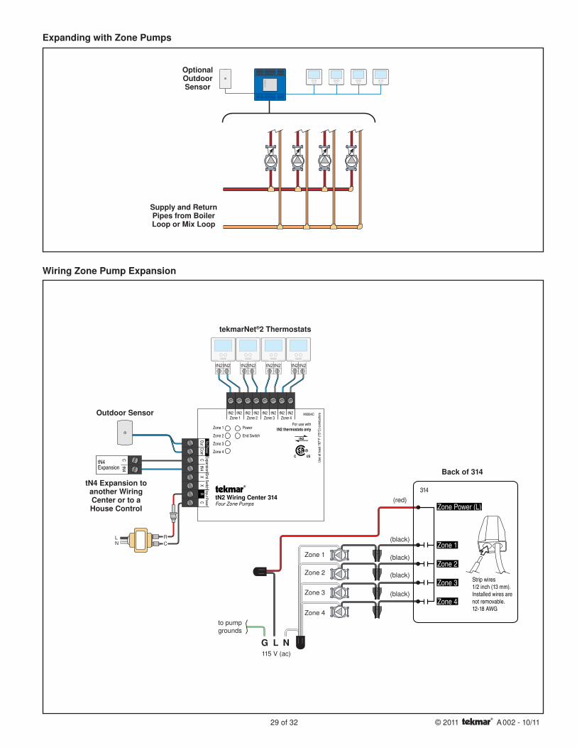
The tekmarNet®2 Wiring Centers 313 and 314 are designed to expand the number of zones available for House Control applications. Two communication wires (tN4 and C) connect to the House Control or to another Wiring Center to add these extra zones with the utmost simplicity. The Wiring Centers can be connected in series, or the wires from each may be pulled back to the House Control and joined there.
Expanding the Number of Zones in a House Control System
tN2tN2tN2tN2tN2tN2tN2tN2
NL
CR
ExpansiontN4
CtN4
115 V (ac)LN G to pump grounds
N L
(red)
(black)
313
Power L
Zone Group Pump
tN4 Expansion to another Wiring Center or to a House Control
Supply and Return Pipes from Boiler Loop or Mix Loop
Expanding with Zone Valves
Wiring Zone Valve Expansion
Outdoor Sensor
OptionalOutdoorSensor
Back of 313
tekmarNet®2 Thermostats
29 of 32 © 2011 A 002 - 10/11
tN2tN2tN2tN2tN2tN2tN2tN2
NL
CR
PowerZone 1
Zone 2
Zone 3
Zone 4
End Switch
Zone 1 Zone 2 Zone 3 Zone 4tN2 tN2 tN2 tN2 tN2 tN2 tN2 tN2
tN2 Wiring Center 314Four Zone Pumps
tN4C
XExpansion
XC
Input PowerR
H8004C
End Switch
For use withtN2 thermostats only
tN2
Use
at le
ast 1
67°F
(75°
C) c
ondu
ctor
s
ComO
utNo Power
ExpansiontN4
CtN4
115 V (ac)L NG
(red)
(black)
(black)
(black)
(black)
to pumpgrounds
Zone 2
Zone 3
Zone 4
Zone 1
Zone Power (L)
Zone 1
Zone 2
Zone 3
Zone 4
Strip wires1/2 inch (13 mm).Installed wires arenot removable.12-18 AWG
314
Supply and Return Pipes from Boiler Loop or Mix Loop
Expanding with Zone Pumps
tN4 Expansion to another Wiring Center or to a House Control
Wiring Zone Pump Expansion
Outdoor Sensor
OptionalOutdoorSensor
tekmarNet®2 Thermostats
Back of 314
© 2011 A 002 - 10/11 30 of 32
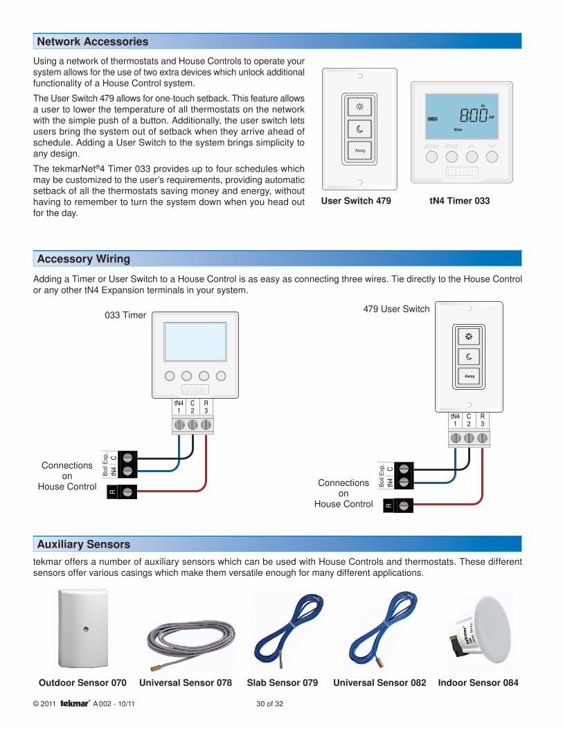
Auxiliary Sensors
Network Accessories
Using a network of thermostats and House Controls to operate your system allows for the use of two extra devices which unlock additional functionality of a House Control system.
The User Switch 479 allows for one-touch setback. This feature allows a user to lower the temperature of all thermostats on the network with the simple push of a button. Additionally, the user switch lets users bring the system out of setback when they arrive ahead of schedule. Adding a User Switch to the system brings simplicity to any design.
The tekmarNet®4 Timer 033 provides up to four schedules which may be customized to the user’s requirements, providing automatic setback of all the thermostats saving money and energy, without having to remember to turn the system down when you head out for the day.
Away
tekmar offers a number of auxiliary sensors which can be used with House Controls and thermostats. These different sensors offer various casings which make them versatile enough for many different applications.
User Switch 479 tN4 Timer 033
Outdoor Sensor 070 Slab Sensor 079 Universal Sensor 082 Indoor Sensor 084
Accessory Wiring
Boi
l Exp
.
Connectionson
House Control Boi
l Exp
.Away
Connectionson
House Control
Adding a Timer or User Switch to a House Control is as easy as connecting three wires. Tie directly to the House Control or any other tN4 Expansion terminals in your system.
033 Timer479 User Switch
Universal Sensor 078
31 of 32 © 2011 A 002 - 10/11
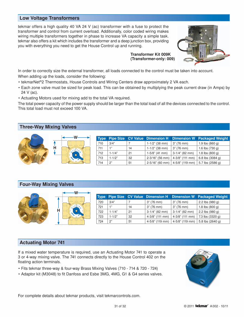
Low Voltage Transformers
tekmar offers a high quality 40 VA 24 V (ac) transformer with a fuse to protect the transformer and control from current overload. Additionally, color coded wiring makes wiring multiple transformers together in phase to increase VA capacity a simple task. tekmar also offers a kit which includes the transformer and a deep junction box, providing you with everything you need to get the House Control up and running.
Transformer Kit 009K(Transformer-only: 009)
Type Pipe Size CV Value Dimension H Dimension W Packaged Weight720 3/4” 7 3” (76 mm) 3” (76 mm) 2.2 lbs (980 g)721 1” 14 3” (76 mm) 3” (76 mm) 1.8 lbs (800 g)722 1-1/4” 21 3-1/4” (82 mm) 3-1/4” (82 mm) 2.2 lbs (980 g)723 1-1/2” 32 4-3/8” (111 mm) 4-3/8” (111 mm) 7.3 lbs (3320 g)724 2” 51 4-5/8” (119 mm) 4-5/8” (119 mm) 5.8 lbs (2640 g)
W
H
Type Pipe Size CV Value Dimension H Dimension W Packaged Weight710 3/4” 7 1-1/2” (38 mm) 3” (76 mm) 1.9 lbs (860 g)711 1” 14 1-1/2” (38 mm) 3” (76 mm) 1.6 lbs (730 g)712 1-1/4” 21 1-5/8” (41 mm) 3-1/4” (82 mm) 1.8 lbs (800 g)713 1-1/2” 32 2-3/16” (56 mm) 4-3/8” (111 mm) 6.8 lbs (3084 g)714 2” 51 2-5/16” (60 mm) 4-5/8” (119 mm) 5.7 lbs (2586 g)
W
H
If a mixed water temperature is required, use an Actuating Motor 741 to operate a 3 or 4-way mixing valve. The 741 connects directly to the House Control 402 on the floating action terminals.
Fits tekmar three-way & four-way Brass Mixing Valves (710 - 714 & 720 - 724)Adaptor kit (M3048) to fit Danfoss and Esbe 3MG, 4MG, G1 & G4 series valves.
••
Three-Way Mixing Valves
Actuating Motor 741
Four-Way Mixing Valves
In order to correctly size the external transformer, all loads connected to the control must be taken into account. When adding up the loads, consider the following:
tekmarNet®2 Thermostats, House Controls and Wiring Centers draw approximately 2 VA each.Each zone valve must be sized for peak load. This can be obtained by multiplying the peak current draw (in Amps) by 24 V (ac).Actuating Motors used for mixing add to the total VA required.
The total power capacity of the power supply should be larger than the total load of all the devices connected to the control. This total load must not exceed 100 VA.
••
•
For complete details about tekmar products, visit tekmarcontrols.com.

© 2011 A 002 - 10/11 32 of 32
Indoor Feedback enables the House Control to fine tune water temperatures based on interior heat gains or losses. This results in greater energy savings
& more constant room temperatures.
DHW Priority over space heating ensures an adequate supply during peak periods of demand.
One Touch adjustment with aUser Switch 479 makes changing between occupied, unoccupied & away temperatures easy for any
homeowner.
Saving
$aving Indicator is displayed when the House Control is using one of its many energy saving features.
Outdoor Temperature monitoring allows the House Control to provide water temperatures that better match space heating requirements.
Setback Schedules entered in a Timer 033 can be used by any tekmarNet® device to
save energy.
Cooling Groups provide a heat /cool interlock between thermostats, preventing conflicts between heating and cooling.
Zone SynchronizationEvery tekmarNet® Thermostat communicates to agree on a common, or ‘synchronized’, start time. The result is a boiler that runs more efficiently and cycles less often.
Zone Post PurgeAt the end of a cycle, the zones are held on while the boiler is off. This moves residual heat out of the boiler and into the zones where it belongs.
Automatic Boiler DifferentialAutomatically adjusting the boiler differential to changing conditions ensures longer running times and reduced boiler short cycling.
Simple ProgrammingHouse Controls are pre-programmed to suit most applications, setting up a House Control System is almost too easy. Once you are finished, access level adjustment helps ensure settings remain as you left them.
MonitoringThe House Control monitors everything from pump run times to outdoor temperature extremes to boiler usage, then organizes it in a simple menu for access at any time.
Plus...
® House Control Benefi ts
© 2011 A 002 - 09/11
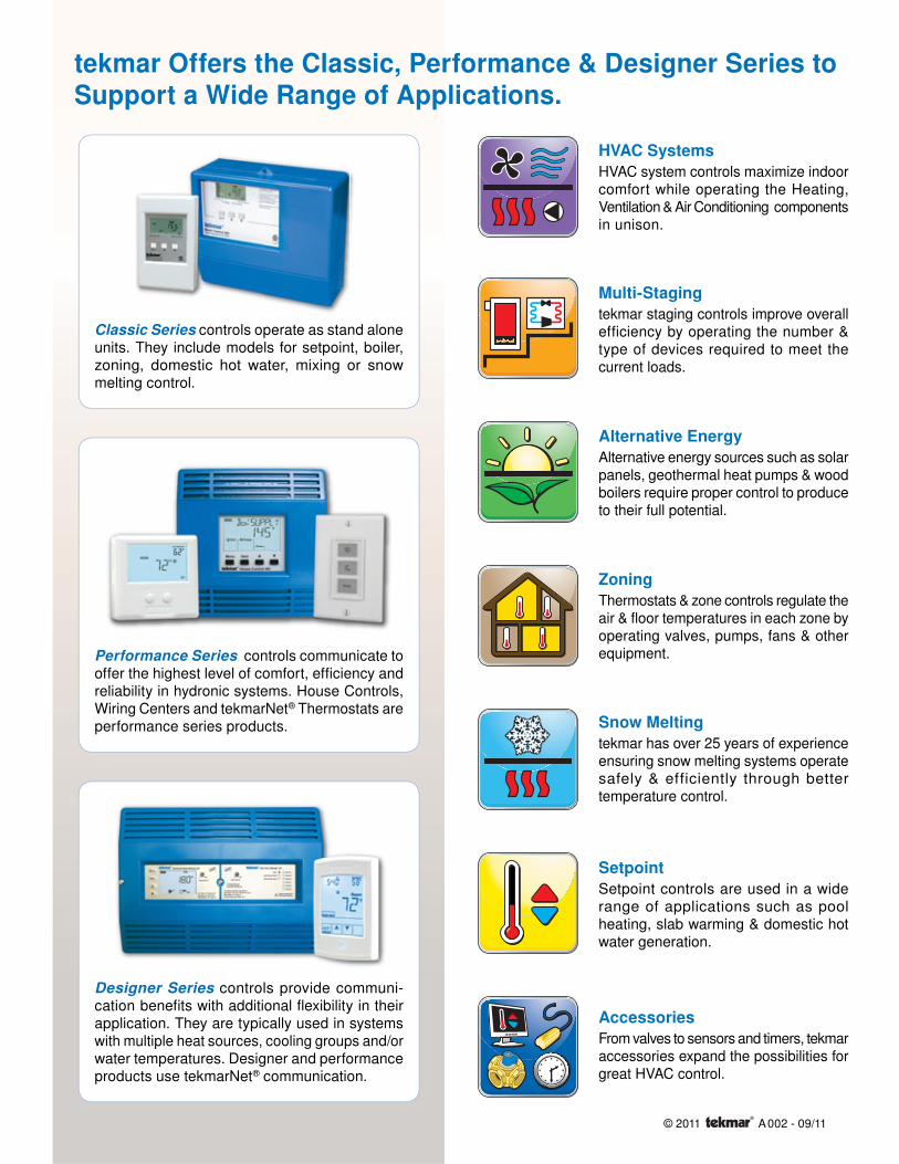
tekmar Offers the Classic, Performance & Designer Series to Support a Wide Range of Applications.
Performance Series controls communicate to offer the highest level of comfort, effi ciency and reliability in hydronic systems. House Controls, Wiring Centers and tekmarNet® Thermostats are performance series products.
Designer Series controls provide communi-cation benefi ts with additional fl exibility in their application. They are typically used in systems with multiple heat sources, cooling groups and/or water temperatures. Designer and performance products use tekmarNet® communication.
Classic Series controls operate as stand alone units. They include models for setpoint, boiler, zoning, domestic hot water, mixing or snow melting control.
AccessoriesFrom valves to sensors and timers, tekmar accessories expand the possibilities for great HVAC control.
HVAC SystemsHVAC system controls maximize indoor comfort while operating the Heating, Ventilation & Air Conditioning components in unison.
Multi-Stagingtekmar staging controls improve overall efficiency by operating the number & type of devices required to meet the current loads.
Alternative EnergyAlternative energy sources such as solar panels, geothermal heat pumps & wood boilers require proper control to produce to their full potential.
ZoningThermostats & zone controls regulate the air & floor temperatures in each zone by operating valves, pumps, fans & other equipment.
Snow Meltingtekmar has over 25 years of experience ensuring snow melting systems operate safely & efficiently through better temperature control.
SetpointSetpoint controls are used in a wide range of applications such as pool heating, slab warming & domestic hot water generation.

tekmar Control Systems Ltd.5100 Silver Star RoadVernon, B.C. Canada
V1B 3K4Tel. 250 545 7749
www.tekmarcontrols.com
Copyright © 2011 by tekmar Control Systems Ltd. Printed in Canada. A002 - 09/11