application of different control techniques to railway
TRANSCRIPT
1
Abstract High speed technology may benefit from the acquisition of smart know-how from the automotive and aerospace sectors. In particular in the automotive sector the application of semi-active magneto-rheological (M-R) dampers has been successfully tested. Application of M-R technology and more generally of semi-active system on rail systems is documented and it is still confined to a limited number of known examples. However there is a growing interest for these kinds of solution which represents a good trade-off between the performance of a fully active system and the reliability assured by passive ones. In this paper some benchmark cases are proposed and used to verify how different control approaches lead to different results both in terms of robustness and performance. Keywords: magneto-rheological dampers, semi-active suspension system, gradient projection method 1 Introduction and state of the art This work summarizes various research activities [1],[2],[3] performed by researchers of university of Florence as direct and un-direct products of a project named Train-New and proposed and financed by Regione Toscana. Typical applications of active and semi-active suspension systems are mainly related to high speed railways or to tramways (metros, light rail etc.): In the first case the research of extreme performances and the remuneration of the railway sector justifies the application of more expensive solutions to the railway sectors. In the second case, tramways, the particular design of the line, design constraints concerning internal volume distribution and/or geometry of the train and in
Paper 185 Application of Different Control Techniques to Railway Semi-Active Suspension Systems B. Allotta1, L. Pugi1, V. Colla2, F. Bartolini1 and F. Cangioli1 1 Dipartimento di Energetica “S. Stecco”, Facoltá di Ingegneria Universitá di Firenze, Italy 2 PERCRO-CEIICP, Scuola Superiore Sant’Anna Polo Sant’Anna Valdera, Pisa, Italy
©Civil-Comp Press, 2012 Proceedings of the First International Conference on Railway Technology: Research, Development and Maintenance, J. Pombo, (Editor), Civil-Comp Press, Stirlingshire, Scotland
2
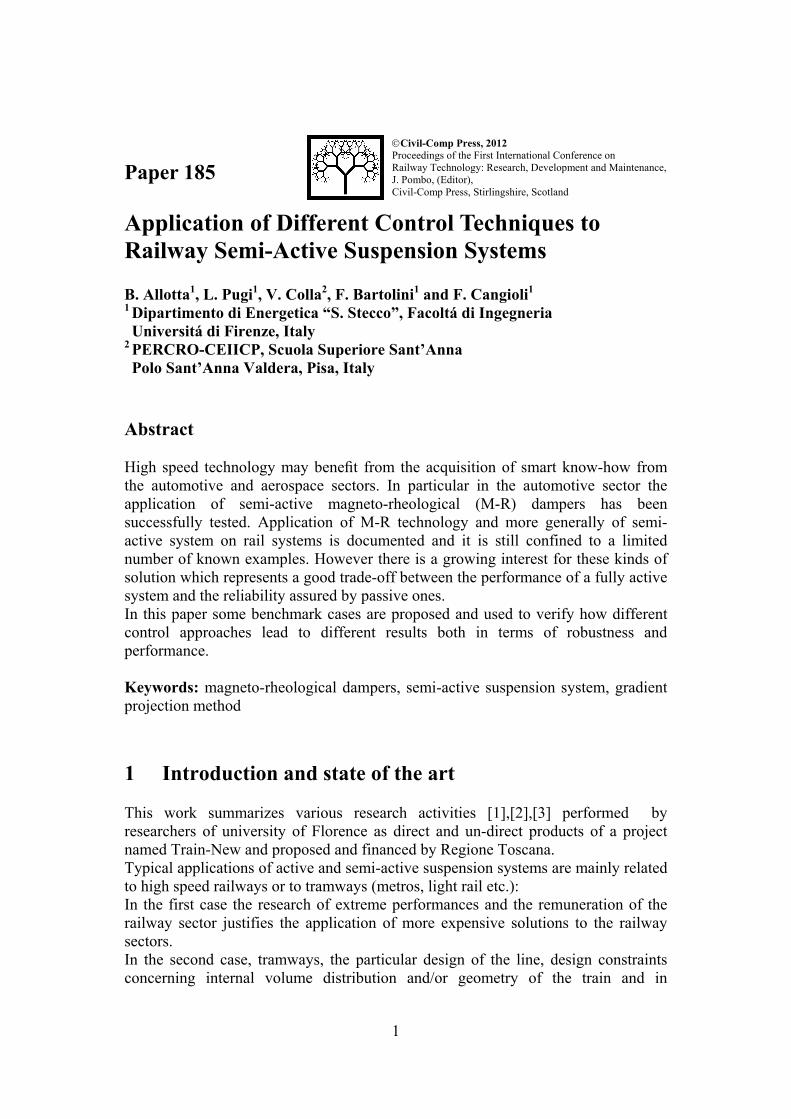
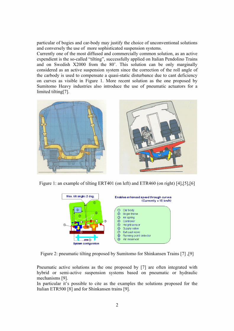
particular of bogies and car-body may justify the choice of unconventional solutions and conversely the use of more sophisticated suspension systems. Currently one of the most diffused and commercially common solution, as an active expendient is the so-called “tilting”, successfully applied on Italian Pendolino Trains and on Swedish X2000 from the 80’. This solution can be only marginally considered as an active suspension system since the correction of the roll angle of the carbody is used to compensate a quasi-static disturbance due to cant deficiency on curves as visible in Figure 1. More recent solution as the one proposed by Sumitomo Heavy industries also introduce the use of pneumatic actuators for a limited tilting[7].
Figure 1: an example of tilting ERT401 (on left) and ETR460 (on right) [4],[5],[6]
Figure 2: pneumatic tilting proposed by Sumitomo for Shinkansen Trains [7] ,[9]
Pneumatic active solutions as the one proposed by [7] are often integrated with hybrid or semi-active suspension systems based on pneumatic or hydraulic mechanisms [9]. In particular it’s possible to cite as the examples the solutions proposed for the Italian ETR500 [8] and for Shinkansen trains [9].

3
In Figure 3, some details concerning the solution proposed for Shinkansen [9],[7] are shown: a pneumatic actuator and a controlled hydraulic damper are coupled trying to compensate limitations of different technologies:
• Pneumatic actuator is the best solution to assure a controllable contact forces and can be used to compensate low frequency disturbances. Bandwidth and involved energy consumptions are unacceptable for the rejection of higher frequency disturbances (over 1Hz). Also a failsafe behaviour can be easily assured.
• Controllable Hydraulic Damper: incompressibility of oil assures an high frequency behaviour, since the element is passive, a failsafe response and more generally, stability and reliability of the control system are easier to be assured using safety by-pass system which can be obtained with different quite known design criteria.
Figure 3: lateral semi-active suspension proposed by Sumitomo for Shinkansen [9]
On the other hand advanced research works from the end of 90’ propose very complex control systems with active and semi-active solutions with multiple actuators able to perform the coordinate control of several actuators passive and/or active and controlled degree of freedom aiming to regulate different indexes of performances of bogies concerning steering, comfort and stability, such as the example many studies carried by the UK groups of Loughborough[10],[11] and RTU of Manchester Metropolitan [12] Universities. Also there are examples of very complex prototypes of mechatronic bogies tested in the prospective of the development of reliable industrial products [13],[14]. In this work authors concentrate their attention on the modelling of simpler systems based on the idea that for the short to medium term development of innovative industrial product, attention has to be focused on semi-active systems and in particular on damping/impedance control, which are quite promising technologies in terms of stability reliability and robustness. Also this kind of solutions may be applied on existing or conventionally designed bogies to upgrade or improve their performances. This choice may be winning considering that all the system affecting expensive experimental activities which can be unaffordable considering the specific features of the railway market.

4
2 Proposed benchmark: The secondary vertical suspension stage of a passenger coach
In order to verify the performances of different control strategies, a classical benchmark[15] is proposed for the optimization of the secondary vertical suspension stage of a passenger coach with a 2-2(trailer axles) or B-B(motorized axles) wheelsets as defined by UIC regulations. Main features of the benchmark coach are shown in Table 1 and Table 2 whose data are referred to the bogie scheme of Figure 4. Dampers of the secondary vertical suspension stage are supposed to be controllable Magneto-Rheological Dampers according the scheme of Figure 4. Body Mass (kg) Ixx (kgm2) Iyy (kgm2) Izz (kgm2) Carbody 52000 130000 2600000 2500000
Bogie 2900 2500 2000 4000
Wheelset 1600 800 160 800
Axlebox 210 5 15 15
Bolster 1020 650 15 680
Table 1: inertial properties of the bodies
Element Transl. Stiffness
X(N/m) Transl. Stiffness Y(N/m)
Transl. Stiffness Z(N/m)
Rot. Stiffness X(N/rad)
Rot. Stiffness y(N/rad)
Rot. Stiffness z(N/rad)
Primary Suspension
850000 850000 800000 10500 10500 0
Secondary Suspension
120000 120000 350000 - - -
Axlebox sutuco 40000000 6500000 40000000 45000 10000 45000
Table 2: elastic characteristics of the elements
Figure 4: scheme of the benchmark bogie The coach model is implemented in Matlab-Simulink™ using the multibody library sim-mechanics™[1].Wheel-rail contact model has been developed in Matlab-Simulink™ during previous research activities [16]. The response of the simulated vehicle is affected by several non-linear effects due to contact geometry, bump stops etc. As a consequence to verify the performances of a regulator is important to apply

5
to the rail vehicle model a pattern of irregularities able to excite different frequencies and amplitudes in order to verify the response in different operating points corresponding to different system behaviour. For this reason a line with the length of 700m and the disturbance pattern visible in Figure 5 is applied.
0 100 200 300 400 500 600 700
-5
0
5
10
15
20
25
x 10-4 Gauge irregularities
Space [m]
[m]
0 100 200 300 400 500 600 700
-2
-1
0
1
2x 10
-3 Twist irregularities
Space [m]
[rad
]
0 100 200 300 400 500 600 700
-0.03
-0.02
-0.01
0
Lateral irregularities
Space [m]
[m]
0 100 200 300 400 500 600 700-4
-2
0
2
4
6
8
x 10-3 Vertical irregularities
Space [m]
[m]
Figure 5: applied irregularity pattern Simple and easy computable performances indexes are needed to evaluate vehicle response especially when iterative parameter optimization procedures of proposed control layouts are used. For this reason authors propose for their research activities a set of six optimization indexes described in and derived as simplified from criteria partially or totally embraced by known standards/regulations [17].
2 2 2 2 2 2( ) ( ) ( ) ( ) ( ) ( )1 1 1 1 1 2 32 2 2 2 2 2( ) ( ) ( ) ( ) ( ) ( )2 2 2 2 1 2 3
2 2 2 2 2 2( ) ( ) ( ) ( ) ( ) ( )3 3 3 3 1 2 3
I rms a rms a rms a I rms a rms a rms ax y z x x x x
I rms a rms a rms a I rms a rms a rms ax y z y y y y
I rms a rms a rms a I rms a rms a rms ax y z z z z z
= + + = + +
= + + = + +
= + + = + +
(1)
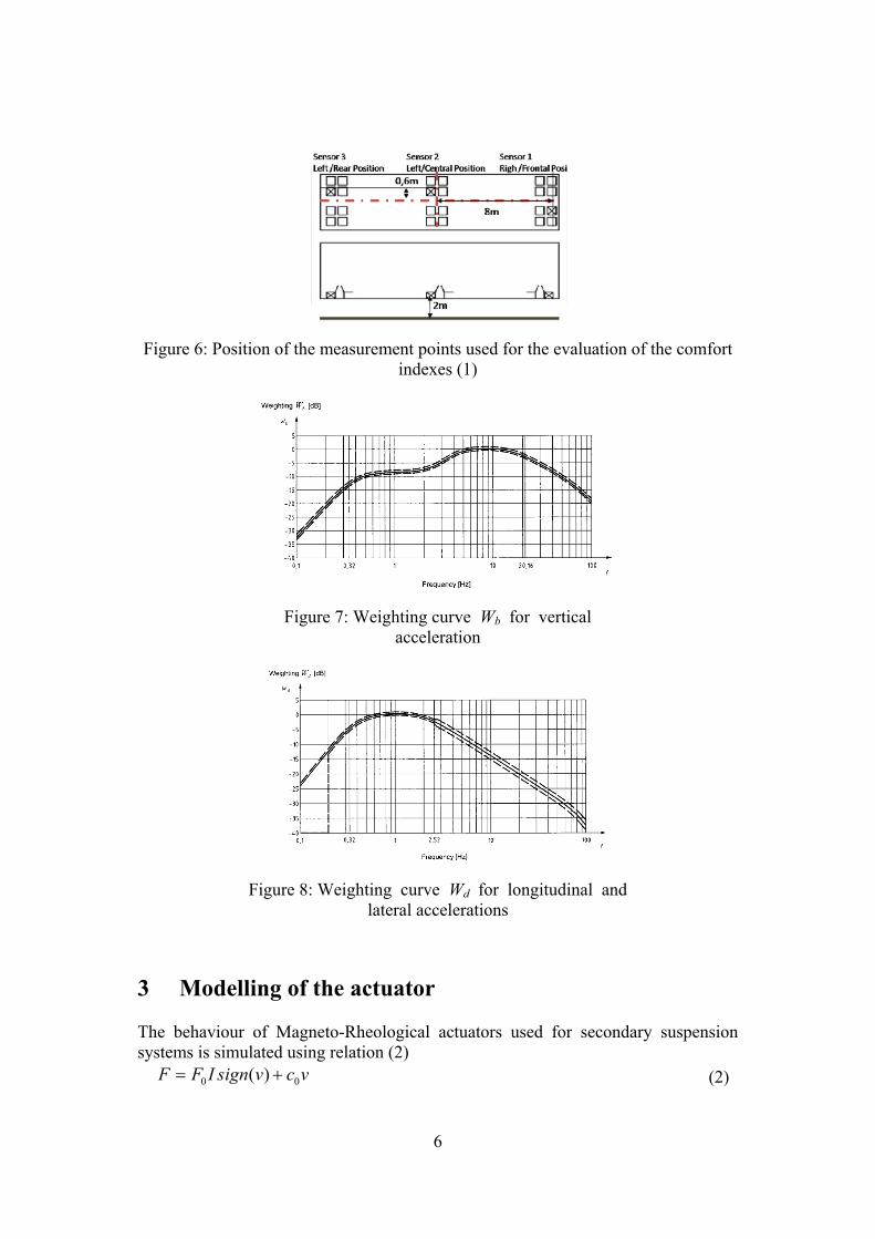
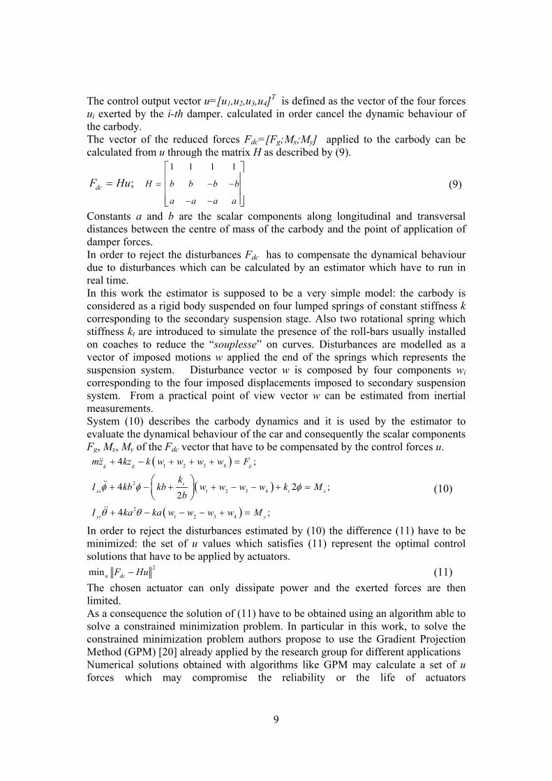
Acceleration measurements aij are measured along on three different points defined by the sub-index i; the corresponding scalar components along x (longitudinal), y(transversal), and z (vertical) axes are indicated by the sub-index j. Position of the measurement points is described by the scheme of Figure 6. Measured accelerations are filtered using the same filters proposed by a known standard whose frequency behaviour is described by the filters of Figure 7, Figure 8.
6
Figure 6: Position of the measurement points used for the evaluation of the comfort indexes (1)
Figure 7: Weighting curve Wb for vertical acceleration
Figure 8: Weighting curve Wd for longitudinal and lateral accelerations
3 Modelling of the actuator The behaviour of Magneto-Rheological actuators used for secondary suspension systems is simulated using relation (2)
0 0( )F F I sign v c v= + (2)

7
F represents the force exerted by the actuator which is roughly proportional (F0 is the constant of proportionality) to the current I used to feed the solenoids which generate the magnetic field that it’s used to modify/control the properties of the M-R fluid inside the actuator. A residual viscosity coefficient c0 is used to model damping which produce a damping force proportional to the actuator speed v even if no current is applied. Dynamical Behaviour of the actuator and the saturation of the magnetic field is modelled introducing the transfer function (3) between the current I and the corresponding reference/desired value Iref .
( )
max
1 is the saturation operator ( is saturated to a value )
ref
ref
sat II
ssat I I
τ=
+ (3)
Since the aim of the model described by (2) and (3) is to describe in a real to realistic way the behaviour of a M-R damper, coefficients are calculated with a best fitting procedure from the simulated behaviour of a complete FEM model of the actuator using Comsol Multiphisic™[1],[2]. Dimensions of the simulated actuator are designed in order to be compatible with the encumbrances available on a railway bogie.
Figure 9: Simulated behaviour of a MR
damper through a FEM model[1],[2]
Figure 10: FEM model of a M-R damper[1],[2]
4 Tested Control Strategies In this work, the performances of three different control strategies are evaluated: • Sky-Hook[18] : each damper works independently on the other one, trying to
keep steady the position of the controlled body; • Dynamic compensation: the dynamical behavior of vehicle car body is estimated
using a simplified linear model, namely a simple plate connected to a movable ground by means of spring and M-R dampers that are actuated in order to minimize the dynamic behavior of the system.
• Dynamic Compensation with acceleration feedback: the dynamic compensation is coupled with a PID controller in order to reject the contribution of non-linear

8
components, such as bump-stops, which cannot be simulated by the online model used by the Dynamic Compensation Strategy [19][20].
4.1 SISO Sky-Hook Control Four M-R dampers are supposed to be applied in parallel to the pneumatic spring of the secondary vertical stage. Each active vertical damper is controlled independently on the other ones, by exerting a force F that is directly proportional to the absolute velocity of the carbody measured on the corresponding damper link (4):
carbody speed measured on the corresponding damper attachment x c
c
F c x
x
= − (4)
Since a M-R damper is a semi-active element, the force is applied only if the corresponding behaviour is dissipative(5):
0 0;x c cP Fv c x v x v= = − < ↔ > (5) The application of eq.(4-5) involve the measurements of the speed of both the ends of the actuator. In particular in this work it’s supposed that speed are estimated by integration from corresponding inertial measurements as follows (6),(7):
c cx x dt= ∫ (6)
( )c bv x x dt= −∫ (7) The sub-indexes b and c are used to indicate measurements referred to bogie and carbody frames. Implementation of the Sky-Hook control, corresponding to equations (4),(5), is quite simple in terms of computational resources, calibration complexity and required hardware. Also the calibration is quite fast as only the Sky-Hook constant cs has to be chosen. Finally, this kind of control strategy ensures a fail-safe behaviour: each damper is controlled independently so a single point failure affect only one of the four actuators. Also the failing actuator works as a damper with a constant viscous constant c0. 4.2 Dynamic Compensation In order to improve the comfort of the carbody three degree of freedom should be controlled: vertical motion (zg vertical position of carbody center of mass and corresponding derivatives) and the corresponding pitch and yaw rotations corresponding to angles φ and θ. The reference performance that an ideal controller would achieve is the minimization of the norm of the acceleration vector described by (8):
, ,T
gx z φ θ⎡ ⎤= ⎣ ⎦ (8)
9
The control output vector u=[u1,u2,u3,u4]T is defined as the vector of the four forces ui exerted by the i-th damper. calculated in order cancel the dynamic behaviour of the carbody. The vector of the reduced forces Fdc=[Fg;Mx;My] applied to the carbody can be calculated from u through the matrix H as described by (9).
1 1 1 1
;dc H b b b b
a a a a
F Hu = − −
− −
⎡ ⎤⎢ ⎥= ⎢ ⎥⎢ ⎥⎣ ⎦
(9)
Constants a and b are the scalar components along longitudinal and transversal distances between the centre of mass of the carbody and the point of application of damper forces. In order to reject the disturbances Fdc has to compensate the dynamical behaviour due to disturbances which can be calculated by an estimator which have to run in real time. In this work the estimator is supposed to be a very simple model: the carbody is considered as a rigid body suspended on four lumped springs of constant stiffness k corresponding to the secondary suspension stage. Also two rotational spring which stiffness kt are introduced to simulate the presence of the roll-bars usually installed on coaches to reduce the “souplesse” on curves. Disturbances are modelled as a vector of imposed motions w applied the end of the springs which represents the suspension system. Disturbance vector w is composed by four components wi corresponding to the four imposed displacements imposed to secondary suspension system. From a practical point of view vector w can be estimated from inertial measurements. System (10) describes the carbody dynamics and it is used by the estimator to evaluate the dynamical behaviour of the car and consequently the scalar components Fg, Mx, My of the Fdc vector that have to be compensated by the control forces u.
( )
( )
( )
1 2 3 4
21 2 3 4
21 2 3 4
4 ;
4 2 ;2
4 ;
g g g
txx t x
yy y
mz kz k w w w w F
kI kb kb w w w w k M
b
I ka ka w w w w M
φ φ φ
θ θ
+ − + + + =
+ − + + − − + =
+ − − − + =
⎛ ⎞⎜ ⎟⎝ ⎠ (10)
In order to reject the disturbances estimated by (10) the difference (11) have to be minimized: the set of u values which satisfies (11) represent the optimal control solutions that have to be applied by actuators.
2minu dcF Hu− (11) The chosen actuator can only dissipate power and the exerted forces are then limited. As a consequence the solution of (11) have to be obtained using an algorithm able to solve a constrained minimization problem. In particular in this work, to solve the constrained minimization problem authors propose to use the Gradient Projection Method (GPM) [20] already applied by the research group for different applications Numerical solutions obtained with algorithms like GPM may calculate a set of u forces which may compromise the reliability or the life of actuators
10
(chattering/excessive switching of actuators). As a consequence to limit an excessive wear of actuators an additional weighting matrix Λ : Λ matrix is diagonal and its elements λii represents the weights individually applied to each element of the vector u. As a consequence GPM minimization algorithm is used to solve the system (12) instead of the (11) in order to introduce the possibility of limiting u :
2 2minu dcF Hu u⎡ ⎤− + Λ⎣ ⎦ (12)
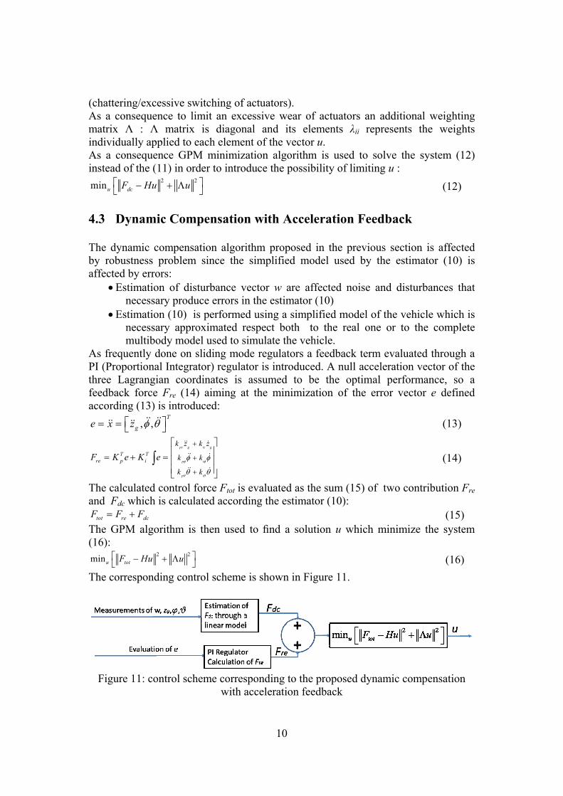
4.3 Dynamic Compensation with Acceleration Feedback The dynamic compensation algorithm proposed in the previous section is affected by robustness problem since the simplified model used by the estimator (10) is affected by errors:
• Estimation of disturbance vector w are affected noise and disturbances that necessary produce errors in the estimator (10)
• Estimation (10) is performed using a simplified model of the vehicle which is necessary approximated respect both to the real one or to the complete multibody model used to simulate the vehicle.
As frequently done on sliding mode regulators a feedback term evaluated through a PI (Proportional Integrator) regulator is introduced. A null acceleration vector of the three Lagrangian coordinates is assumed to be the optimal performance, so a feedback force Fre (14) aiming at the minimization of the error vector e defined according (13) is introduced:
, ,T
ge x z φ θ⎡ ⎤= = ⎣ ⎦ (13)
pz g iz g
p i
p i
T Tre p i
k z k z
k k
k k
F K e K eφ φ
θ θ
φ φ
θ θ
+
+
+
⎡ ⎤⎢ ⎥= + = ⎢ ⎥⎢ ⎥⎣ ⎦
∫
(14)
The calculated control force Ftot is evaluated as the sum (15) of two contribution Fre and Fdc which is calculated according the estimator (10):
tot re dcF F F= + (15) The GPM algorithm is then used to find a solution u which minimize the system (16):
2 2minu totF Hu u⎡ ⎤− + Λ⎣ ⎦ (16) The corresponding control scheme is shown in Figure 11.
Figure 11: control scheme corresponding to the proposed dynamic compensation
with acceleration feedback
11
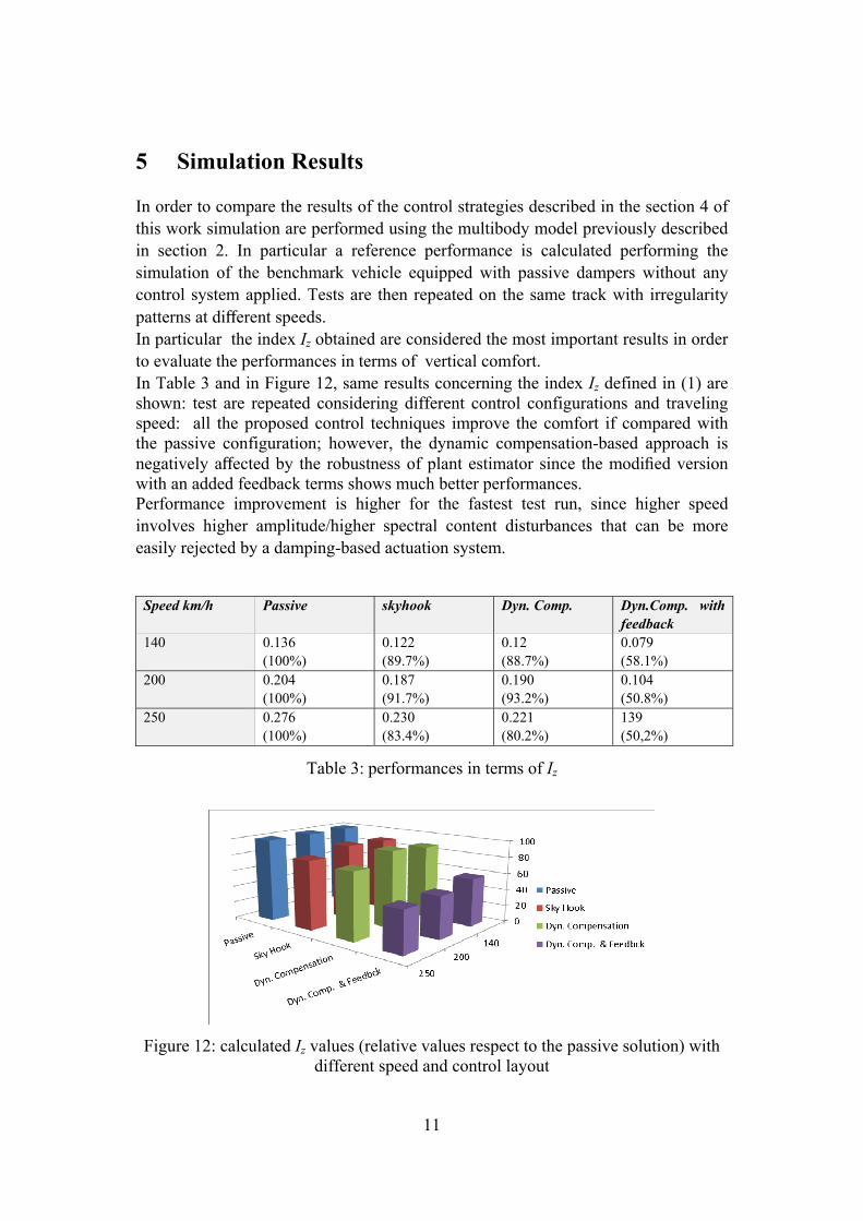
5 Simulation Results In order to compare the results of the control strategies described in the section 4 of this work simulation are performed using the multibody model previously described in section 2. In particular a reference performance is calculated performing the simulation of the benchmark vehicle equipped with passive dampers without any control system applied. Tests are then repeated on the same track with irregularity patterns at different speeds. In particular the index Iz obtained are considered the most important results in order to evaluate the performances in terms of vertical comfort. In Table 3 and in Figure 12, same results concerning the index Iz defined in (1) are shown: test are repeated considering different control configurations and traveling speed: all the proposed control techniques improve the comfort if compared with the passive configuration; however, the dynamic compensation-based approach is negatively affected by the robustness of plant estimator since the modified version with an added feedback terms shows much better performances. Performance improvement is higher for the fastest test run, since higher speed involves higher amplitude/higher spectral content disturbances that can be more easily rejected by a damping-based actuation system.
Speed km/h Passive skyhook Dyn. Comp. Dyn.Comp. with feedback
140 0.136 (100%)
0.122 (89.7%)
0.12 (88.7%)
0.079 (58.1%)
200 0.204 (100%)
0.187 (91.7%)
0.190 (93.2%)
0.104 (50.8%)
250 0.276 (100%)
0.230 (83.4%)
0.221 (80.2%)
139 (50,2%)
Table 3: performances in terms of Iz
Figure 12: calculated Iz values (relative values respect to the passive solution) with different speed and control layout
12
Calculated performance indexes defined by (1) considering different control configuration and traveling speed are shown in Table 4, Table 5, Table 6, and Table 7: all the proposed control strategies involve comfort benefit in all the three sensor locations, damping all the three comfort-related vibrations of the carbody, such as vertical translation and roll and pitch rotations. Lateral and longitudinal motions (indexes Iy and Ix) are less affected by different control strategies since only the vertical dampers of the secondary suspension stage are actuated.
Speed km/h I1 I2 I3 Ix Iy Iz
140 0.177 0.105 0.221 0.0144 0.108 0.136 200 0.281 0.171 0.314 0.0229 0.164 0.204 250 0.296 0.251 0.385 0.0262 0.150 0.276
Table 4: perf. indexes for passive reference configuration
Speed km/h I1 I2 I3 Ix Iy Iz
140 0.167 0.102 0.206 0.0139 0.108 0.122 200 0.260 0.174 0.290 0.0224 0.158 0.187 250 0.256 0.221 0.326 0.0256 0.141 0.230
Table 5: perf. indexes calculated for skyhook control
Speed km/h I1 I2 I3 Ix Iy Iz
140 0.170 0.0984 0.197 0.0139 0.105 0.121 200 0.260 0.179 0.290 0.0222 0.156 0.190 250 0.250 0.214 0.325 0.0260 0.142 0.222
Table 6: perf. indexes calculated for Dynamic Compensation
Speed km/h I1 I2 I3 Ix Iy Iz
140 0.113 0.0745 0.143 0.0127 0.0811 0.079 200 0.134 0.0960 0.151 0.0170 0.0750 0.104 250 0.179 0.141 0.199 0.0230 0.104 0.139
Table 7: perf. indexes for Mod. Dyn. Comp. (feedback added)
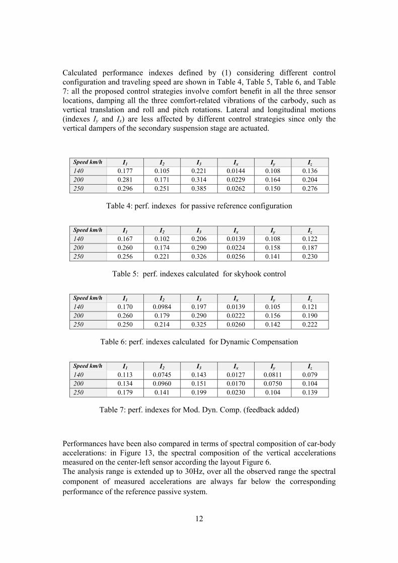
Performances have been also compared in terms of spectral composition of car-body accelerations: in Figure 13, the spectral composition of the vertical accelerations measured on the center-left sensor according the layout Figure 6. The analysis range is extended up to 30Hz, over all the observed range the spectral component of measured accelerations are always far below the corresponding performance of the reference passive system.

13
In terms of robustness and reliability of the control, this behaviour is very attractive since there is no-noise regeneration over a wide range of frequencies. This feature is quite useful in terms of system stability, as it involves a lower sensitivity to un-damped mechanical modes of the system which may be excited by the action of actuators. Higher performances are reached by the “modified dynamic compensation with acceleration feedback” since the added PI acceleration feedback is able to reject the disturbances due to modelling errors between the real plant and the simplified estimation model used to estimate the dynamical behaviour of the system.
Figure 13: spectral composition of vertical acceleration[m/s2] measured on center left sensor (according the layout of Figure 6) as a function of frequency [Hz]
Performance of Sky-Hook control are lower compared respect to centralized control strategies. However the implementation is much simpler. Also the robustness of the Sky-hook controller is much higher respect to centralized control strategies especially when the modelling errors between estimator and real controlled plant (the vehicle) are higher. Also the behaviour of the Sky-Hook control is very robust in case of failure for example of one of the actuators. The failure is reproduced by cutting out the corresponding command signal. In Figure 14 some results are shown: in particular in Figure 14 the spectral composition of vertical acceleration measured on center-left sensor (according the layout of Figure 6) is shown: the observed performances are degraded exhibiting an higher rolling motion of carbody; In particular the unbalanced application of forces due to the unavailability of a damper (simulated fault) causes a cross/mutual excitation of roll and pitch modes of the secondary stage suspensions; however the behavior is still smooth and the performances are better than in the passive reference simulation.
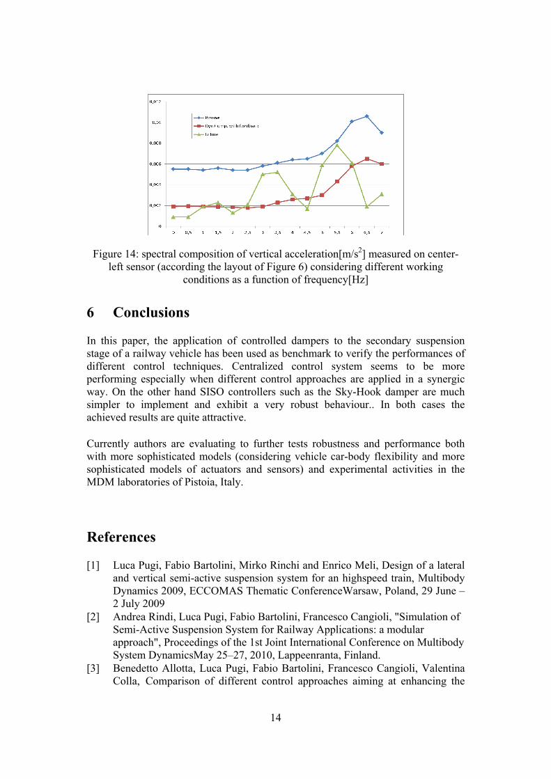
14
Figure 14: spectral composition of vertical acceleration[m/s2] measured on center-left sensor (according the layout of Figure 6) considering different working
conditions as a function of frequency[Hz] 6 Conclusions In this paper, the application of controlled dampers to the secondary suspension stage of a railway vehicle has been used as benchmark to verify the performances of different control techniques. Centralized control system seems to be more performing especially when different control approaches are applied in a synergic way. On the other hand SISO controllers such as the Sky-Hook damper are much simpler to implement and exhibit a very robust behaviour.. In both cases the achieved results are quite attractive. Currently authors are evaluating to further tests robustness and performance both with more sophisticated models (considering vehicle car-body flexibility and more sophisticated models of actuators and sensors) and experimental activities in the MDM laboratories of Pistoia, Italy. References [1] Luca Pugi, Fabio Bartolini, Mirko Rinchi and Enrico Meli, Design of a lateral
and vertical semi-active suspension system for an highspeed train, Multibody Dynamics 2009, ECCOMAS Thematic ConferenceWarsaw, Poland, 29 June – 2 July 2009
[2] Andrea Rindi, Luca Pugi, Fabio Bartolini, Francesco Cangioli, "Simulation of Semi-Active Suspension System for Railway Applications: a modular approach", Proceedings of the 1st Joint International Conference on Multibody System DynamicsMay 25–27, 2010, Lappeenranta, Finland.
[3] Benedetto Allotta, Luca Pugi, Fabio Bartolini, Francesco Cangioli, Valentina Colla, Comparison of different control approaches aiming at enhancing the
15
comfort of a railway vehicle, 2010 IEEE/ASME International Conference on Advanced Intelligent Mechatronics Montréal, Canada, July 6-9, 2010
[4] Terrasse-Joly Une nouvelle voiture dite “pendulaire” destinee aux tres grandes vitesses” Revue Generale des chemins de fer Novembre 1957
[5] Camposano Italy's Pendolino a succesful experiment International Railway Journal June 1979
[6] B. Dalla Chiara, G.Hauser, A. Elia, I treni ad assetto variabile: evoluzione, prestazioni e prospettive Ing Ferroviaria luglio agosto 2008.
[7] Sumitomo Metals, Technical Documentation [8] Trenitalia SPA Disegno 0005 1586291: Complessivo Laterale Attiva,
Archivio disegni Trenitalia [9] K.Sasaki A lateral semi-active suspension of tilting train, Quarterly Report of
RTRI Vol. 41 (2000) , No. 1 pp.11-15 [10] Li J., Goodall R.M., Mei T.X., Li H., 2003, Steering Controllers for Rail
Vehicles with Independently-Driven Wheel Motors (extended summary), 18th IAVSD Symposium: Dynamics of Vehicles on Roads and Tracks, Kanagawa, Japan
[11] R. Goodall, Active Railway Suspensions: Implementation Status and Technological Trends,Vehicle System Dynamics, Volume 28, Issue 2 & 3 August 1997 , pages 87 – 117
[12] Liang B. and Iwnicki S.D. ‘Independently rotating wheels with induction motors for high-speed trains’ Journal of Control Science and Engineering, Vol 2011 (2011) article ID 968286 7 pages
[13] S. Iwnicky, R.Goodall, T.X.Mei, Handbook of railway vehicle Dynamics, Cap. 11 Active Suspensions, CRC PRESS Taylor and Francis
[14] Streiter R, Boller M, Riege B, Schneider R and Himmelstein G: Active Lateral Suspension for High Speed Trains - A Step Towards the Mechatronic Bogie, World Congress on Railway Research, Cologne, November, 2001.
[15] W. H. Liao, D. H. Wang, Semiactive Vibration Control of Train Suspension Systems via Magnetorheological Dampers ,Journal of Intelligent Material Systems and Structures, Vol. 14, No. 3, 161-172 (2003)
[16] Enrico Meli; Monica Malvezzi; Susanna Papini; Luca Pugi; Mirko Rinchi; Andrea Rindi A railway vehicle multibody model for real-time applications Vehicle System Dynamics: International Journal of Vehicle Mechanics and Mobility, Volume 46, Issue 12, First published 2008, Pages 1083 – 1105 10.1080/0042311070179075.
[17] Draft prEN 12299 Railway Applications-Ride Comfort for Passengers-Measurement and Evaluation July 2006 Version
[18] H. Li, R.M. Goodall, Linear and non linear skyhook damping control laws for active railway vehicle suspensions, Control Eng. Practice 7 843-850,1999
[19] K. Khalil, Nonlinear Systems (3rd ed.), Upper Saddle River, NJ: Prentice Hall, 2002
[20] V.I. Utkin, Sliding Mode Control Design Principles and Applications to Electric Drives, IEEE Transactions on Industrial Electronics, Vol. 40, Issue 1, 1993, pp. 23-36
16
[21] Luemberger, D. G., 1984, Linear and Nonlinear Programming, Addison-Wesley Publishing Company, Reading, Massachusetts.
[22] B. Allotta, V. Colla and G. Bioli, Kinematic Control of Robots With Joint Constraints, Journal of Dynamic Systems, Measurement, and Control Sep. 1999, Vol. 121/435