application of additive technology in precision casting
TRANSCRIPT

International Journal of Engineering and Management Sciences (IJEMS) Vol. 5. (2020). No. 2
DOI: 10.21791/IJEMS.2020.2.6.
43
Application of Additive Technology in Precision
Casting
D. HALÁPI, L. VARGA
University of Miskolc, Faculty of Material Science and Engineering [email protected]
Abstract. In this paper the surface of the prepared test specimens had been examined with light microscopy and
surface roughness measurements. In order to improve the surface smoothness of PLA specimens, application of ethyl
acetate was required. After this surface treatment, microscopic images were taken again. The melting and
decomposition temperatures of the materials had been determined using derivatography. The chosen method was
precision casting with gypsum molding. Also, the plaster molds had been burnt out according to the predefined
melting and firing diagram. The measurement series shows that the samples produced by 3D printing can also be
used in the field of precision casting. They provide greater freedom of design, more sophisticated pieces, and
prototypes can be finished in a shorter amount of time.
Introduction
Nowadays, 3D printing is an extremely emerging and developing industry, one of the tools of Rapid
Prototyping Technologies. Until the '80s, there were basically only two processes known as "RPT", and
by the end of the decade a new revolutionary additive prototype manufacturing technology had
emerged.[2]
Prototype production can be divided into 3 main groups, which are illustrated in Figure 1:[1]
• Formative manufacturing;
• Subtractive manufacturing;
• Additive manufacturing
Additive Manufacturing (AM) is a technology which developed rapidly in the last few years and
becoming more and more widespread. Often referred in the media as 3D printing. As a matter of fact,
AM has been around for much longer than most people would think. The first systems were
commercially available in the early 1990s. Additive Manufacturing (AM) technologies have evolved
into a plethora of manufacturing technologies which are radically changing the manufacturing
industry's horizons through transformative capabilities for a high level of design in complexity,
customization, and flexibility. [1]

International Journal of Engineering and Management Sciences (IJEMS) Vol. 5. (2020). No. 2
DOI: 10.21791/IJEMS.2020.2.6.
44
a)
b)
c) Figure 1. Rapid prototyping technologies
Possibilities of implementing prototype production: a) formative manufacturing;
b) subtractive manufacturing; c) additive manufacturing[2]
1. 3D printing
AM has grown 50 times its size in the market during the last decade and has exceeded the growth rate
of 18% in the last 4 years (Wohler Report 2016). At the same time, AM's scope of application has
expanded significantly, not only for prototypes, but also for tools and many other functional
components, providing them high added value. It starts to outgrow itself and is slowly emerging as a
production technology. Over the last 5 years, there has been a significant increase in applications for
direct part production, especially in the space industry, medical technology and general engineering.
In many of these functional applications, AM's most sought capability is called “Design for
Functionality” (DFF), which focuses on maximizing the functions and performance of structures with
minimal use of resources (eg, raw materials, production time, failure, etc.). This, in turn, requires the
very users of AM technology to be fully aware of AM's design capabilities and limitations. However,
such knowledge base is currently not generally available. At the present, knowledge about AM remains
empirical, especially in the areas of process development, manufacturability and design optimization.
In many applications, special knowledge and expertise based on individual products or special
combinations of materials and processes are usually inadequate or lacking. Although research and
development activities have gradually shifted towards more systematic study of process physics in
recent years, the coherent theoretical structure of many AM technologies remains an open challenge.
As a result, the industry has grown tremendously and today there are hundreds of thousands, if not
millions, of machines around the world. Being this widespread comes with many challenges and many

International Journal of Engineering and Management Sciences (IJEMS) Vol. 5. (2020). No. 2
DOI: 10.21791/IJEMS.2020.2.6.
45
solutions. As they become more widely available, a variety of machines and applications range from
very simple to extremely complex.
Figure 2. Evolution of the concept of AM, trend towards industrial applicability
2. Precision casting
Precision casting has a huge part in the history, even 4,000 years ago the Egyptians used a very similar
type of technology. However, its debut as a manufacturing technology can only be dated, since the
beginning of the 20th century. Around this time, it was used for making shell-forming materials with
high fire-resistance properties, which had adequate surface smoothness and strength properties.
The real series production began in World War II, mainly for producing castings of a high complexity
which other technologies were not be able to achieve.
The great advantage of this technology is that the surface of the castings does not have to be machined
afterwards. Special waxes and plastics are used as the material of the samples. Wax samples are
usually made by injection, then glued onto a conical wax rod and the resulting bunches are embedded
in molding materials. Embedding can be done by ceramic peeling or refractory plaster casting.
Advantages of precision castings are the following:
• Melt patterns allow for undivided shape formation and eliminate cores.
• The liquid molding material follows the shape of the sample with great accuracy. Practical
accuracy is ± 0.05-0.1 mm
• An excellent non-burnishing casting surface is available.
• The high fire-resistance molding material allows the liquid metal to be cast into pre-heated
mold up to 900 ° C. As a result, it is possible to produce precise, gas-tight, thin-walled castings from
alloys that otherwise have poor casting properties.

International Journal of Engineering and Management Sciences (IJEMS) Vol. 5. (2020). No. 2
DOI: 10.21791/IJEMS.2020.2.6.
46
• The precision casting process are suitable to produce small sized castings. Castings heavier
than 5-10 kg and larger than 400-500 mm are difficult to form, which can be considered as an upper
limit of production.
• Precision casting offers significant technological and economic benefits, particularly in
manufacturing complex, thin-walled components. Precision castings are finished parts, but rarely
require minimal post processing. The economic benefits are parallel to the complexity of the process,
so if the complexity in production is growing and the used material becomes more expensive, the
process will become more economical.
2.1. Gypsum molding process
Gypsum mold waxing technology is used in special cases. The wax pattern is reproduced from a metal
masterpiece or carved directly from wax by hand or CAD / CAM system with coordinate milling. The
gypsum mold is resistant to the casting temperature, pressure, and has a porous, smooth surface. The
limiting element of the plaster mold is a steel cylinder, which provides the necessary support during
casting. The cuvette is made of flat-faced steel sheet when casting technology is performed by
centrifugal casting machines. The steel mantle is perforated when the mold is vacuum manufactured.
Economically and technologically, both are equally sufficient. The only difference between them is the
forces which are affecting the molten metal.[6]
The wax assembly is placed in a rubber bottomed cuvette and the wax body is being soldered to it. The
rubber bell-shaped stems and the wax will be the inlet channel, the pelvis and the standing. The
bouquet is mounted on the trunk from top to bottom, as shown in Figure 3. The wax samples are
applied evenly, preferably as often as possible. From the bottom to the top, the size of these objects are
changing. On the lower part, the bigger objects are placed, while moving up to the top, the placed
object sizes are becoming more and more small. This distribution is making a more controlled and
smoother flow rate during production.
Figure 3. Wax assembly

International Journal of Engineering and Management Sciences (IJEMS) Vol. 5. (2020). No. 2
DOI: 10.21791/IJEMS.2020.2.6.
47
3. 3D printed parameterization
The geometry designed in the CAD-CAM software was used in two printer software, in both cases the
positioning in the workspace was carried out by the respective software. 3D printing softwares are
usually using STL format and quite the number of them are freely accessible.
Figure 4. shows the planned geometry, which later were used as a base for dimensional accuracy
testing.
Figure 4. Test specimen
The geometry intended for printing had to be adapted to the present technology. Instead of a solid
body, it is possible to create a hollow shell geometry to save material and time. In the case of
polymerization due to the liquid attributes the user has to make sure that this liquid to sufficiently fill
the target volume.
3.1. FDM 3D printer process
When operating a 3D printer, you can change the internal filling of the selected bodies, which saves
time and expense. Figure 5. shows the Cetus FDM fiber-based 3D printer software, where the test
specimen has been placed in the software calculated orientation. The printing parameters were the
following:
printing temperature: 210 ° C
layer thickness: 0.1 mm
Density factor: 15%
supports, underlay
During my experiments the only factor which changed was the layer thickness, all the other
parameters remained unchanged (such as print speed, print temperature, fill factor). Table 1. shows
the relation between layer thickness and print time.
Layer thickness [m] Printing time [perc] Weigth [g]
100m 52,1 4
200m 29,3 4
300m 21,3 4 Table 1. This is a table.

International Journal of Engineering and Management Sciences (IJEMS) Vol. 5. (2020). No. 2
DOI: 10.21791/IJEMS.2020.2.6.
48
The results of the table show that the film thickness significantly affects the print time.
Figure 5. slicer software
3.2. SLA 3D printer process
As for the Formlabs Form 2 type SLA 3D printer, other kind of input parameters can be specified. The
customisable options are more wider, than in the case of the previously mentioned model, but
depending on the raw material it is mainly given by the software itself. During my examinations the
utilised layer thickness was 25 µm. Figure 6 shows the "Preform" 3D printing software that can be
used with a Form 2 printer. The software is extremely user-friendly, simple and also has an automatic
fast parameterization function. The automatic parameterizer does not always offer the right solution,
so it is advisable to check the given orientation and support structure. The software allows modifiable
parameters such as layer thickness (depending on the material), geometry size, orientation, support
placement, and geometry placement on the building table.
Figure 6. SLA prited specimen

International Journal of Engineering and Management Sciences (IJEMS) Vol. 5. (2020). No. 2
DOI: 10.21791/IJEMS.2020.2.6.
49
4. Microscopy analysis
The purpose of my examinations was to detect the surface defects of the printed test bodies and to
check them after surface treatments. Light microscopy images of test specimens printed with an FDM
fiber printer are shown in the following figures. On their surface, the difference between the layers is
clearly visible. Figure 7-9. immediately shows the interlayer groove resulting in an uneven surface.
Figure 7. 300m layer thickness
Figure 8. 200m layer thickness
Figure 9. 100m layer thickness

International Journal of Engineering and Management Sciences (IJEMS) Vol. 5. (2020). No. 2
DOI: 10.21791/IJEMS.2020.2.6.
50
There is a clear difference between the test pieces printed at different layer thicknesses. Geometries
with greater layers’ thickness were ready significantly earlier, but this printing speed required
additional post processing. Because of this inaccuracy, the groove depths between layer were much
bigger, thus even the abrasion surface treatment resulted in a dense surface structure. For further
examinations the utilized layer thickness was 100 µm. Of all the surface treatments I applied, ethyl
acetate gave the best results. Wet grinding, however, also results in success, but it must go through
several successive abrasive surface to get the desired result.
5. Derivatographic examination
Three different types of sample materials were examined in question of their suitability for precision
casting technology.
From each examined material, 100 mg were taken to derivatographic examination. The mass change of
the results is expressed as a percentage.[5]
Figure 10. Result of the Freeman Ruby Red injectable wax derivatographic measurement
The derivatographic curve shows that the wax starts to flow even at low temperatures (~ 68 ° C),
stable up to 200 ° C and decomposes above 200 ° C.

International Journal of Engineering and Management Sciences (IJEMS) Vol. 5. (2020). No. 2
DOI: 10.21791/IJEMS.2020.2.6.
51
In the first phase, the heating rate was set at 50 °C/h up to 150°C/h. This step was followed by a 1-2
hours long heat retention, then a burning out phase recommended by the manufacturer, as shown in
Figure 11.
The derivatographic curve of the formlabs castable resin feedstock shows that melting occurs at much
higher temperatures, which is followed by decomposition.
Figure 11. Result of the Formlabs castable resin derivatographic measurement
The derivatography test confirmed the values given by the manufacturer, according to which pre-
heating is carried out in two steps, first at a heating rate of 70 ° C / h up to 180 ° C, followed by heating
at a heating rate of 120 ° C / h.
Figure 12. Result of the PLA derivatographic measurement

International Journal of Engineering and Management Sciences (IJEMS) Vol. 5. (2020). No. 2
DOI: 10.21791/IJEMS.2020.2.6.
52
6. Surface roughness analysis
In all cases, the actual surface of a printed part differs from the geometric or nominal surface of the
component drawing determined by the figure and dimensions. Due to their inaccuracy, the available
measuring instruments can only measure the real surface with a certain approximation. The true size
of geometry can never be determined in reality. Frequency diagrams based on the actual dimensions
of the subdivisions provide good information on the nature of scattering and their extent.[4]
Figure 13. PLA sample
Figure 14. PLA sample treatment
7. Results of evaluation of tests
In order to compare the surface quality, size accuracy tests were performed. These measurements
were split into two main parts, firstly the dimensional difference from the planned 3D geometry. The
second part involved the examination of the surface roughness on the finished test specimens. The
following figures illustrate the surface differences between the samples and the molded test bodies.
Figure 15. Master sample, wax sample.

International Journal of Engineering and Management Sciences (IJEMS) Vol. 5. (2020). No. 2
DOI: 10.21791/IJEMS.2020.2.6.
53
Figure 16. 3D printed PLA specimen, untreated (left side), treated (right side).
Figure 17. Test specimen after casting process
In the case of the samples produced by 3D printing, the reference (3D geometry) was given, but in the
case of precision injection molding technology with wax injection, the master sample had to be
produced first.
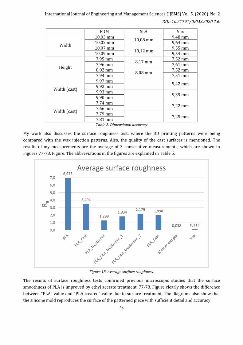
In terms of dimensional accuracy, the two parameters observed were width (10mm) and height
(8mm). Table 4 contains the measured results.
In FDM 3D printed geometries, the width of the test body corresponds to the construction orientation
in the Z direction and the height to the construction orientation in the X to Y direction.
International Journal of Engineering and Management Sciences (IJEMS) Vol. 5. (2020). No. 2
DOI: 10.21791/IJEMS.2020.2.6.
54
FDM SLA Vax
Width
10,03 mm 10,08 mm
9,48 mm 10,02 mm 9,64 mm 10,07 mm
10,12 mm 9,55 mm
10,09 mm 9,54 mm
Height
7,95 mm 8,17 mm
7,52 mm 7,96 mm 7,61 mm 8,02 mm
8,08 mm 7,52 mm
7,94 mm 7,51 mm
Width (cast)
9,97 mm 9,42 mm
9,92 mm 9,93 mm
9,39 mm 9,90 mm
Width (cast)
7,74 mm 7,22 mm
7,66 mm 7,79 mm
7,25 mm 7,81 mm Table 2. Dimensional accuracy
My work also discusses the surface roughness test, where the 3D printing patterns were being
compared with the wax injection patterns. Also, the quality of the cast surfaces is mentioned. The
results of my measurements are the average of 3 consecutive measurements, which are shown in
Figures 77-78. Figure. The abbreviations in the figures are explained in Table 5.
Figure 18. Average surface roughness.
The results of surface roughness tests confirmed previous microscopic studies that the surface
smoothness of PLA is improved by ethyl acetate treatment. 77-78. Figure clearly shows the difference
between "PLA" value and "PLA treated" value due to surface treatment. The diagrams also show that
the silicone mold reproduces the surface of the patterned piece with sufficient detail and accuracy.
6,973
3,494
1,299 1,834
2,179 1,998
0,038 0,113 0,0
1,0
2,0
3,0
4,0
5,0
6,0
7,0
Ra
Average surface roughness

International Journal of Engineering and Management Sciences (IJEMS) Vol. 5. (2020). No. 2
DOI: 10.21791/IJEMS.2020.2.6.
55
Figure 19. Smoothness height.
Summary
I examined the surface of the prepared test specimens with light microscope, and made surface
roughness measurements. In order to improve the surface smoothness of PLA specimens, application
of ethyl acetate required. After this surface treatment, microscopic images were taken again;
I have determined the melting and decomposition temperatures of the materials using
derivatography;
I applied the method of precision casting with gypsum molding. I burned out the plaster molds
according to the predefined melting and firing diagram. After casting, the finished castings were
certified by surface roughness and light microscopy;
The measurement series shows that the samples produced by 3D printing can also be used in the field
of precision casting. They provide greater freedom of design, more sophisticated pieces can be made,
and prototype pieces can be finished in a short time.
Acknowledgment
I would like to thank Philament Kft., which provided the fibers under investigation, and the Foundry
Institute for the opportunity to make the measurements possible.
“The described article was carried out as part of the EFOP-3.6.1-16-00011 “Younger and Renewing
University – Innovative Knowledge City – institutional development of the University of Miskolc
aiming at intelligent specialisation” project implemented in the framework of the Szechenyi 2020
37,224
19,591
7,478
12,082 11,638 11,942
0,373 0,782
0,0
5,0
10,0
15,0
20,0
25,0
30,0
35,0
40,0R
z
Smoothness height

International Journal of Engineering and Management Sciences (IJEMS) Vol. 5. (2020). No. 2
DOI: 10.21791/IJEMS.2020.2.6.
56
program. The realization of this project is supported by the European Union, co-financed by the
European Social Fund.”
References
[1] E. Pei, M. Monzón, and A. Bernard, Additive Manufacturing – Developments in Training and
Education. 2018.
[2] B. Redwood, F. Schöffer, and B. Garret, “The 3D Printing Handbook,” 3D Hubs, p. 304, 2017.
[3] L. Yang, “Introducing the State-of-the-Art Additive Manufacturing Research in Education,” in
Additive Manufacturing -- Developments in Training and Education, E. Pei, M. Monzón, and A.
Bernard, Eds. Cham: Springer International Publishing, 2019, pp. 53–65
[4] T. I. Bartha Miklós, Bándy Alajos, Cseke József, Devecz János, Eleőd András, Klementis Csilla,
Márialigeti János, Nyitrai János, Nyolcas Mihály, Sváb János, Műszaki ábrázolás II. Budapest:
Typotex kiadó, 2011.
[5] F. Mária, “A földtani kutatásban alkalmazott termoanalitikai módszerek,” 1982.
[6] L. Ernő, Precíziós öntés. Budapest: Műszaki Könyvkiadó, 1967.