application note of lte measurement - 정광인스텍 lte application note mt8820c-e-f-6
TRANSCRIPT

Application Note
LTE Measurement
MT8820C Radio Communication Analyzer
MT8820C LTE Application Note MT8820C-E-F-6
2
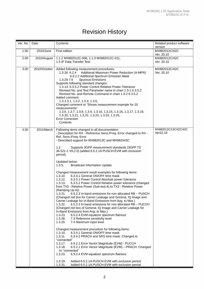
Revision History
Ver. No Date Contents Related product software version
1.00 2010/June First edition MX882012C/42C Ver. 20.10
2.00 2010/August 1.1.2 MX882012C-006, 1.1.3 MX882012C-011, 1.5 IP Data Transfer Test
MX882012C/42C Ver. 20.10
3.00 2010/October Added following measurement procedures: 1.3.26. 6.2.4 Additional Maximum Power Reduction (A-MPR)
6.6.2.2 Additional Spectrum Emission Mask 1.3.29 7.9 Spurious Emissions
Supports following standard changes: 1.3.13. 6.3.5.2 Power Control Relative Power Tolerance Revised No. and Test Parameter name in chart 1.3-1 6.3.5.2 Revised No. and Remote Command in chart 1.3-2 6.3.5.2
Added comment 1.3,1.3.1, 1.3.2, 1.3.3, 1.3.5,
Changed comment to "Shows measurement example for 20 measurements".
1.3.6, 1.3.7, 1.3.8, 1.3.9, 1.3.10, 1,3,15, 1.3.16, 1.3.17, 1.3.19, 1.3.20, 1.3.21, 1.3.22, 1.3.23, 1.3.24, 1.3.25,
Error Correction Contents
MX882012C/42C Ver. 20.10
4.00 2011/March Following items changed in all documentation - Description for RX - Reference Sens./Freq. Error changed to RX - Ref. Sens./Freq. Error - Described support for MX882013C and MX882043C
1.2 Supports 3GPP measurement standards (3GPP TS 36.521-1 V9.2.0) (added 6.5.2.1A PUSCH-EVM with exclusion period).
Updated below: 1.3.5. Broadcast Information Update
Changed measurement result examples for following items: 1.3.10. 6.3.4.1 General ON/OFF time mask 1.3.12. 6.3.5.1 Power Control Absolute power tolerance 1.3.13. 6.3.5.2 Power Control Relative power tolerance (changed from TX3 - Relative Power (Sub-test A) to TX3 - Relative Power (Ramping Up A)) 1.3.21. 6.5.2.3 In-band emissions for non-allocated RB – PUSCH (Changed red box for Carrier Leakage and General, IQ Image and Carrier Leakage for In-Band Emissions from Avg. to Max.) 1.3.22. 6.5.2.3 In-band emissions for non-allocated RB – PUCCH (Changed red box of General, IQ Image and Carrier Leakage for In-Band Emissions from Avg. to Max.) 1.3.23. 6.5.2.4 EVM equalizer spectrum flatness 1.3.28. 7.3 Reference sensitivity level 1.3.29. 7.4 Maximum input level
Changed measurement procedure for following items: 1.3.10. 6.3.4.1 General ON/OFF time mask 1.3.11. 6.3.4.2 PRACH and SRS time mask: Changed to “connected” 1.3.17. 6.5.2.1 Error Vector Magnitude (EVM) - PUCCH 1.3.18. 6.5.2.1 Error Vector Magnitude (EVM) – PRACH: Changed
to “connected” 1.3.23. 6.5.2.4 EVM equalizer spectrum flatness
1.3.19. Added 6.5.2.1A PUSCH-EVM with exclusion period 1.3.31. Added 6.5.2.1A PUSCH-EVM with exclusion period
MX882012C/13C/42C/43C Ver22.10
MT8820C LTE Application Note MT8820C-E-F-6
3
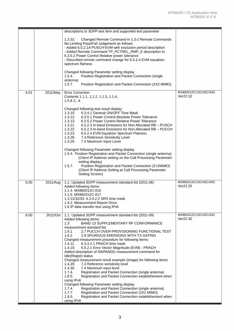
descriptions to 3GPP test item and supported test parameter
1.3.32. Changed Remote Command in 1.3-2 Remote Commands list Limiting Pass/Fail Judgement as follows: - Added 6.5.2.1A PUSCH-EVM with exclusion period description - Added Remote Command TP_PCTREL_RMP_E description to 6.3.5.2 Power Control Relative power tolerance - Described remote command change for 6.5.2.4 EVM equalizer spectrum flatness
Changed following Parameter setting display 1.5.4. Position Registration and Packet Connection (single antenna) 1.5.7. Position Registration and Packet Connection (2X2 MIMO)
4.01 2011/May Error Correction Contents 1.1.1, 1.1.2, 1.1.3, 1.1.4, 1.5.8 2., 4.
Changed following test result display 1.3.10. 6.3.4.1 General ON/OFF Time Mask 1.3.12. 6.3.5.1 Power Control Absolute Power Tolerance 1.3.13. 6.3.5.2 Power Control Relative Power Tolerance 1.3.21. 6.5.2.3 In-band Emissions for Non Allocated RB – PUSCH 1.3.22. 6.5.2.3 In-band Emissions for Non Allocated RB – PUCCH 1.3.23. 6.5.2.4 EVM Equalizer Spectrum Flatness 1.3.28. 7.3 Reference Sensitivity Level 1.3.29. 7.4 Maximum Input Level
Changed following Parameter setting display 1.5.4. Position Registration and Packet Connection (single antenna)
(Client IP Address setting on the Call Processing Parameter setting display)
1.5.7. Position Registration and Packet Connection (2×2MIMO) (Client IP Address Setting at Call Processing Parameter Setting Screen)
MX882012C/13C/42C/43C Ver22.10
5.00 2011/Aug 1.1. Updated 3GPP measurement standard list (2011-06) Added following items: 1.1.4. MX882012C-016 1.1.5. MX882012C-017 1.3.12/32/33. 6.3.4.2.2 SRS time mask 1.4.2. Measurement Report Once 1.6 IP data transfer test using IPv6
MX882012C/13C/42C/43C Ver22.20
6.00 2011/Oct 1.1. Updated 3GPP measurement standard list (2011-09) Added following items: 1.3 BAND 13 SUPPLEMENTARY RF CONFORMANCE measurement standard list 1.6.1 2.7 PUCCH OVER-PROVISIONING FUNCTIONAL TEST 1.6.2 2.9 SPURIOUS EMISSIONS WITH TX GATING Changed measurement procedure for following items: 1.4.11. 6.3.4.2.1 PRACH time mask 1.4.19. 6.5.2.1 Error Vector Magnitude (EVM) - PRACH Added description of SWPANDG measurement command for Idle(Regist) status Changed measurement result example (image) for following items 1.4.29. 7.3 Reference sensitivity level 1.4.30. 7.4 Maximum input level 1.7.4. Registration and Packet Connection (single antenna) 1.8.5. Registration and Packet Connection establishement when using IPv6 Changed following Parameter setting display 1.7.4. Registration and Packet Connection (single antenna) 1.7.7. Registration and Packet Connection (2X2 MIMO) 1.8.5. Registration and Packet Connection establishement when using IPv6
MX882012C/13C/42C/43C Ver22.30
MT8820C LTE Application Note MT8820C-E-F-6
4
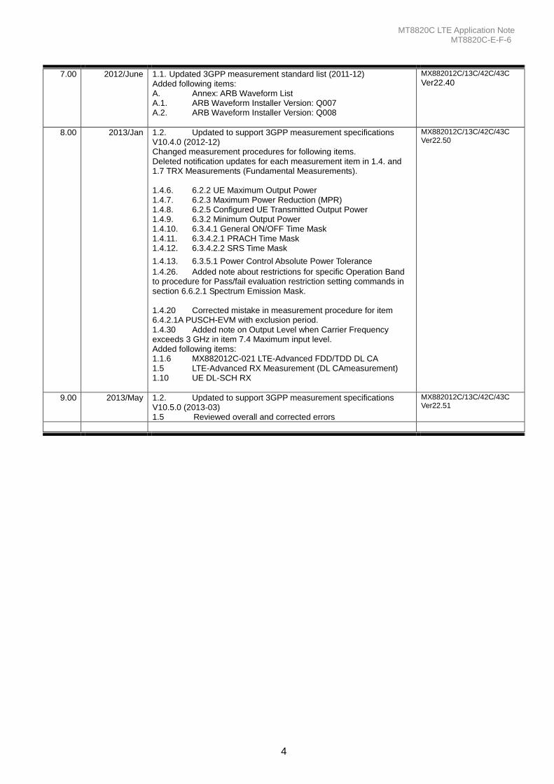
7.00 2012/June 1.1. Updated 3GPP measurement standard list (2011-12) Added following items: A. Annex: ARB Waveform List A.1. ARB Waveform Installer Version: Q007 A.2. ARB Waveform Installer Version: Q008
MX882012C/13C/42C/43C Ver22.40
8.00 2013/Jan 1.2. Updated to support 3GPP measurement specifications V10.4.0 (2012-12) Changed measurement procedures for following items. Deleted notification updates for each measurement item in 1.4. and 1.7 TRX Measurements (Fundamental Measurements). 1.4.6. 6.2.2 UE Maximum Output Power 1.4.7. 6.2.3 Maximum Power Reduction (MPR) 1.4.8. 6.2.5 Configured UE Transmitted Output Power 1.4.9. 6.3.2 Minimum Output Power 1.4.10. 6.3.4.1 General ON/OFF Time Mask 1.4.11. 6.3.4.2.1 PRACH Time Mask 1.4.12. 6.3.4.2.2 SRS Time Mask
1.4.13. 6.3.5.1 Power Control Absolute Power Tolerance
1.4.26. Added note about restrictions for specific Operation Band to procedure for Pass/fail evaluation restriction setting commands in section 6.6.2.1 Spectrum Emission Mask. 1.4.20 Corrected mistake in measurement procedure for item 6.4.2.1A PUSCH-EVM with exclusion period. 1.4.30 Added note on Output Level when Carrier Frequency exceeds 3 GHz in item 7.4 Maximum input level. Added following items: 1.1.6 MX882012C-021 LTE-Advanced FDD/TDD DL CA 1.5 LTE-Advanced RX Measurement (DL CAmeasurement) 1.10 UE DL-SCH RX
MX882012C/13C/42C/43C Ver22.50
9.00 2013/May 1.2. Updated to support 3GPP measurement specifications V10.5.0 (2013-03) 1.5 Reviewed overall and corrected errors
MX882012C/13C/42C/43C Ver22.51
MT8820C LTE Application Note MT8820C-E-F-6
5
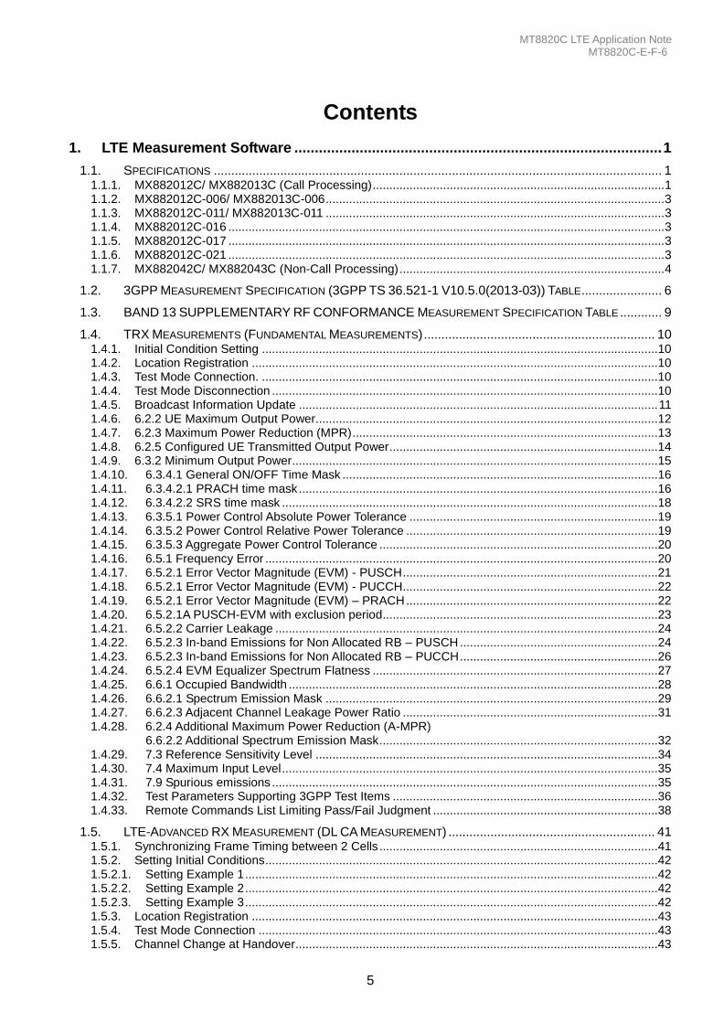
Contents
1. LTE Measurement Software .......................................................................................... 1
1.1. SPECIFICATIONS ................................................................................................................................ 1 1.1.1. MX882012C/ MX882013C (Call Processing) ....................................................................................... 1 1.1.2. MX882012C-006/ MX882013C-006 ..................................................................................................... 3 1.1.3. MX882012C-011/ MX882013C-011 ..................................................................................................... 3 1.1.4. MX882012C-016 .................................................................................................................................. 3 1.1.5. MX882012C-017 .................................................................................................................................. 3 1.1.6. MX882012C-021 .................................................................................................................................. 3 1.1.7. MX882042C/ MX882043C (Non-Call Processing) ............................................................................... 4
1.2. 3GPP MEASUREMENT SPECIFICATION (3GPP TS 36.521-1 V10.5.0(2013-03)) TABLE ....................... 6
1.3. BAND 13 SUPPLEMENTARY RF CONFORMANCE MEASUREMENT SPECIFICATION TABLE ............ 9
1.4. TRX MEASUREMENTS (FUNDAMENTAL MEASUREMENTS) .................................................................. 10 1.4.1. Initial Condition Setting ...................................................................................................................... 10 1.4.2. Location Registration ......................................................................................................................... 10 1.4.3. Test Mode Connection. ...................................................................................................................... 10 1.4.4. Test Mode Disconnection ................................................................................................................... 10 1.4.5. Broadcast Information Update ........................................................................................................... 11 1.4.6. 6.2.2 UE Maximum Output Power...................................................................................................... 12 1.4.7. 6.2.3 Maximum Power Reduction (MPR) ........................................................................................... 13 1.4.8. 6.2.5 Configured UE Transmitted Output Power ................................................................................ 14 1.4.9. 6.3.2 Minimum Output Power ............................................................................................................. 15 1.4.10. 6.3.4.1 General ON/OFF Time Mask .............................................................................................. 16 1.4.11. 6.3.4.2.1 PRACH time mask ........................................................................................................... 16 1.4.12. 6.3.4.2.2 SRS time mask ................................................................................................................ 18 1.4.13. 6.3.5.1 Power Control Absolute Power Tolerance .......................................................................... 19 1.4.14. 6.3.5.2 Power Control Relative Power Tolerance ........................................................................... 19 1.4.15. 6.3.5.3 Aggregate Power Control Tolerance ................................................................................... 20 1.4.16. 6.5.1 Frequency Error ..................................................................................................................... 20 1.4.17. 6.5.2.1 Error Vector Magnitude (EVM) - PUSCH ............................................................................ 21 1.4.18. 6.5.2.1 Error Vector Magnitude (EVM) - PUCCH............................................................................ 22 1.4.19. 6.5.2.1 Error Vector Magnitude (EVM) – PRACH ........................................................................... 22 1.4.20. 6.5.2.1A PUSCH-EVM with exclusion period.................................................................................. 23 1.4.21. 6.5.2.2 Carrier Leakage .................................................................................................................. 24 1.4.22. 6.5.2.3 In-band Emissions for Non Allocated RB – PUSCH ........................................................... 24 1.4.23. 6.5.2.3 In-band Emissions for Non Allocated RB – PUCCH ........................................................... 26 1.4.24. 6.5.2.4 EVM Equalizer Spectrum Flatness ..................................................................................... 27 1.4.25. 6.6.1 Occupied Bandwidth .............................................................................................................. 28 1.4.26. 6.6.2.1 Spectrum Emission Mask ................................................................................................... 29 1.4.27. 6.6.2.3 Adjacent Channel Leakage Power Ratio ............................................................................ 31 1.4.28. 6.2.4 Additional Maximum Power Reduction (A-MPR)
6.6.2.2 Additional Spectrum Emission Mask ................................................................................... 32 1.4.29. 7.3 Reference Sensitivity Level ...................................................................................................... 34 1.4.30. 7.4 Maximum Input Level ................................................................................................................ 35 1.4.31. 7.9 Spurious emissions ................................................................................................................... 35 1.4.32. Test Parameters Supporting 3GPP Test Items ............................................................................... 36 1.4.33. Remote Commands List Limiting Pass/Fail Judgment ................................................................... 38
1.5. LTE-ADVANCED RX MEASUREMENT (DL CA MEASUREMENT) ........................................................... 41 1.5.1. Synchronizing Frame Timing between 2 Cells ................................................................................... 41 1.5.2. Setting Initial Conditions ..................................................................................................................... 42 1.5.2.1. Setting Example 1 ........................................................................................................................... 42 1.5.2.2. Setting Example 2 ........................................................................................................................... 42 1.5.2.3. Setting Example 3 ........................................................................................................................... 42 1.5.3. Location Registration ......................................................................................................................... 43 1.5.4. Test Mode Connection ....................................................................................................................... 43 1.5.5. Channel Change at Handover............................................................................................................ 43
MT8820C LTE Application Note MT8820C-E-F-6
6
1.5.6. Bandwidth Change at Handover ........................................................................................................ 43 1.5.7. Changing PCell DL RB Allocation ...................................................................................................... 43 1.5.8. Changing SCell DL RB Allocation ...................................................................................................... 44 1.5.9. PCell UL RB Allocation Change ......................................................................................................... 44 1.5.10. Stopping Test Mode ........................................................................................................................ 44 1.5.11. 7.3A.2 Reference sensitivity level for CA (intra-band contiguous DL CA without UL CA) .............. 45 1.5.12. 7.3A.3 Reference sensitivity level for CA(inter-band DL CA without UL CA) ................................. 46 1.5.13. 7.4A.2 Maximum input level for CA (intra-band contiguous DL CA without UL CA) ....................... 47
1.6. UE REPORT ..................................................................................................................................... 48 1.6.1. Measurement Report ......................................................................................................................... 48 1.6.2. Measurement Report ......................................................................................................................... 48
1.7. BAND 13 SUPPLEMENTARY RF CONFORMANCE MEASUREMENT ....................................... 49 1.7.1. 2.7 PUCCH OVER-PROVISIONING FUNCTIONAL TEST ............................................................... 49 1.7.2. 2.9 SPURIOUS EMISSIONS WITH TX GATING ............................................................................... 50
1.8. IP DATA TRANSFER TEST ................................................................................................................. 52 1.8.1. Setting MT8820C and Application Server .......................................................................................... 53 1.8.2. Setting Client PC ................................................................................................................................ 55 1.8.3. Initial Condition Setting ...................................................................................................................... 55 1.8.4. Position Registration and Packet Connection (single antenna) ......................................................... 55 1.8.5. UDP Throughput Test for IP Data Transfer (single antenna) ............................................................. 58 1.8.6. TCP Throughput Test for IP Data Transfer (single antenna) .............................................................. 59 1.8.7. Position Registration and Packet Connection (2x2MIMO) ................................................................. 60 1.8.8. UDP Throughput Test for IP Data Transfer (2x2MIMO) ..................................................................... 62 1.8.9. TCP Throughput Test for IP Data Transfer (2x2MIMO) ...................................................................... 63 1.8.10. Disconnection ................................................................................................................................. 63
1.9. IP DATA TRANSFER TEST USING IPV6 ................................................................................................ 64 1.9.1. TCP/IP version 6 installation (Windows XP server/client PC only) .................................................... 65 1.9.2. Server PC connection and setting (Windows XP) .............................................................................. 67 1.9.3. Server PC connection and setting (Windows 7/Vista) ....................................................................... 68 1.9.4. Initial condition setting when using IPv6 ............................................................................................ 70 1.9.5. Position registration and packet connection establishement when using IPv6 .................................. 71 1.9.6. IP data transfer UDP throughput verification (2x2 MIMO) when using IPv6 ...................................... 74
1.10. UE DL-SCH RX .............................................................................................................................. 75 1.10.1. UE Category ................................................................................................................................... 75 1.10.2. Code Rate ....................................................................................................................................... 76 1.10.3. Error Free Setting ........................................................................................................................... 78
A. ANNEX: ARB WAVEFORM LIST ............................................................................................................. 79
A.1. ARB Waveform Installer Version: Q007 ......................................................................................... 79A.2. ARB Waveform Installer Version: Q008 .......................................................................................... 80
MT8820C LTE Application Note MT8820C-E-F-6
1
1. LTE Measurement Software
1.1. Specifications
1.1.1. MX882012C/ MX882013C (Call Processing)
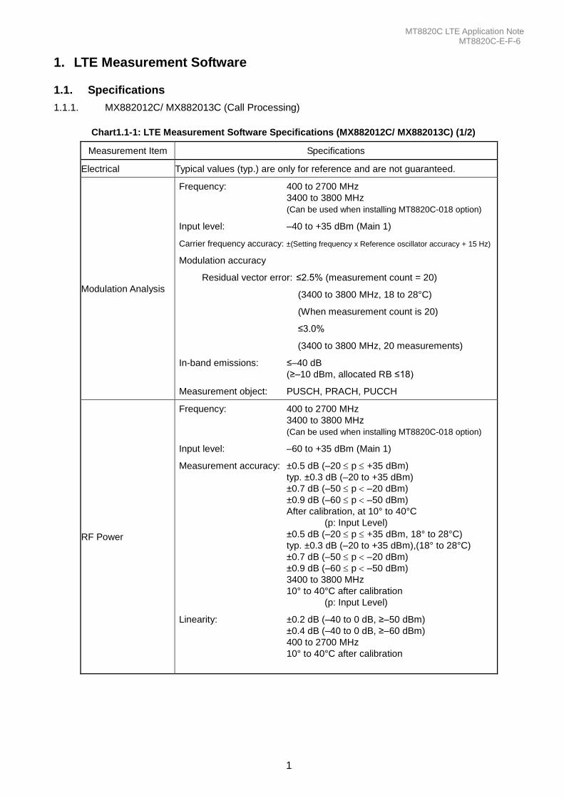
Chart1.1-1: LTE Measurement Software Specifications (MX882012C/ MX882013C) (1/2)
Measurement Item Specifications
Electrical Typical values (typ.) are only for reference and are not guaranteed.
Modulation Analysis
Frequency: 400 to 2700 MHz
3400 to 3800 MHz
(Can be used when installing MT8820C-018 option)
Input level: –40 to +35 dBm (Main 1)
Carrier frequency accuracy: ±(Setting frequency x Reference oscillator accuracy + 15 Hz)
Modulation accuracy
Residual vector error: ≤2.5% (measurement count = 20)
(3400 to 3800 MHz, 18 to 28°C)
(When measurement count is 20)
≤3.0%
(3400 to 3800 MHz, 20 measurements)
In-band emissions: ≤–40 dB
(≥–10 dBm, allocated RB ≤18)
Measurement object: PUSCH, PRACH, PUCCH
RF Power
Frequency: 400 to 2700 MHz
3400 to 3800 MHz
(Can be used when installing MT8820C-018 option)
Input level: –60 to +35 dBm (Main 1)
Measurement accuracy: ±0.5 dB (–20 p +35 dBm)
typ. ±0.3 dB (–20 to +35 dBm)
±0.7 dB (–50 p –20 dBm)
±0.9 dB (–60 p –50 dBm)
After calibration, at 10° to 40°C
(p: Input Level)
±0.5 dB (–20 p +35 dBm, 18° to 28°C)
typ. ±0.3 dB (–20 to +35 dBm),(18° to 28°C)
±0.7 dB (–50 p –20 dBm)
±0.9 dB (–60 p –50 dBm)
3400 to 3800 MHz
10° to 40°C after calibration
(p: Input Level)
Linearity: ±0.2 dB (–40 to 0 dB, ≥–50 dBm)
±0.4 dB (–40 to 0 dB, ≥–60 dBm)
400 to 2700 MHz
10° to 40°C after calibration
MT8820C LTE Application Note MT8820C-E-F-6
2
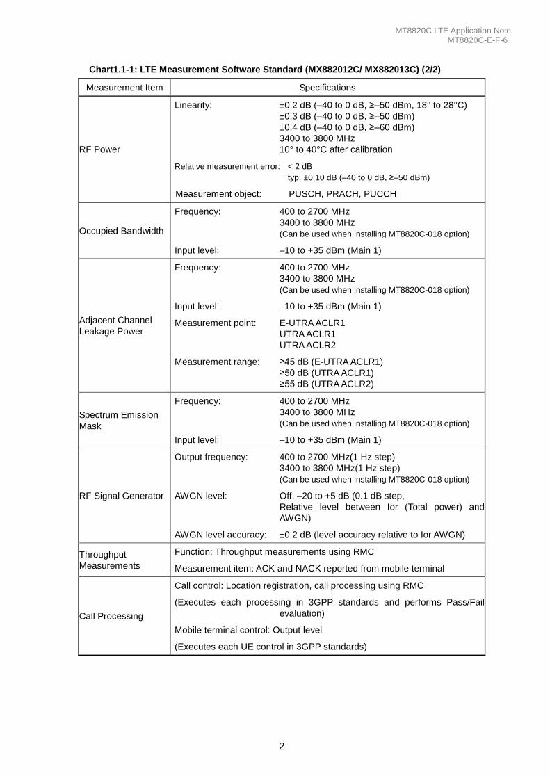
Chart1.1-1: LTE Measurement Software Standard (MX882012C/ MX882013C) (2/2)
Measurement Item Specifications
RF Power
Linearity: ±0.2 dB (–40 to 0 dB, ≥–50 dBm, 18° to 28°C)
±0.3 dB (–40 to 0 dB, ≥–50 dBm)
±0.4 dB (–40 to 0 dB, ≥–60 dBm)
3400 to 3800 MHz
10° to 40°C after calibration
Relative measurement error: < 2 dB
typ. ±0.10 dB (–40 to 0 dB, ≥–50 dBm)
Measurement object: PUSCH, PRACH, PUCCH
Occupied Bandwidth
Frequency: 400 to 2700 MHz
3400 to 3800 MHz
(Can be used when installing MT8820C-018 option)
Input level: –10 to +35 dBm (Main 1)
Adjacent Channel
Leakage Power
Frequency: 400 to 2700 MHz
3400 to 3800 MHz
(Can be used when installing MT8820C-018 option)
Input level: –10 to +35 dBm (Main 1)
Measurement point: E-UTRA ACLR1
UTRA ACLR1
UTRA ACLR2
Measurement range: ≥45 dB (E-UTRA ACLR1)
≥50 dB (UTRA ACLR1)
≥55 dB (UTRA ACLR2)
Spectrum Emission
Mask
Frequency: 400 to 2700 MHz
3400 to 3800 MHz
(Can be used when installing MT8820C-018 option)
Input level: –10 to +35 dBm (Main 1)
RF Signal Generator
Output frequency: 400 to 2700 MHz(1 Hz step)
3400 to 3800 MHz(1 Hz step)
(Can be used when installing MT8820C-018 option)
AWGN level: Off, –20 to +5 dB (0.1 dB step,
Relative level between Ior (Total power) and
AWGN)
AWGN level accuracy: ±0.2 dB (level accuracy relative to Ior AWGN)
Throughput
Measurements
Function: Throughput measurements using RMC
Measurement item: ACK and NACK reported from mobile terminal
Call Processing
Call control: Location registration, call processing using RMC
(Executes each processing in 3GPP standards and performs Pass/Fail
evaluation)
Mobile terminal control: Output level
(Executes each UE control in 3GPP standards)
MT8820C LTE Application Note MT8820C-E-F-6
3
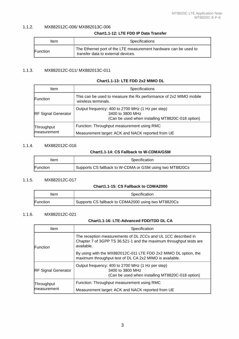
1.1.2. MX882012C-006/ MX882013C-006
Chart1.1-12: LTE FDD IP Data Transfer
Item Specifications
Function The Ethernet port of the LTE measurement hardware can be used to
transfer data to external devices.
1.1.3. MX882012C-011/ MX882013C-011
Chart1.1-13: LTE FDD 2x2 MIMO DL
Item Specifications
Function This can be used to measure the Rx performance of 2x2 MIMO mobile
wireless terminals.
RF Signal Generator
Output frequency: 400 to 2700 MHz (1 Hz per step)
3400 to 3800 MHz
(Can be used when installing MT8820C-018 option)
Throughput
measurement
Function: Throughput measurement using RMC
Measurement target: ACK and NACK reported from UE
1.1.4. MX882012C-016
Chart1.1-14: CS Fallback to W-CDMA/GSM
Item Specification
Function Supports CS fallback to W-CDMA or GSM using two MT8820Cs
1.1.5. MX882012C-017
Chart1.1-15: CS Fallback to CDMA2000
Item Specification
Function Supports CS fallback to CDMA2000 using two MT8820Cs
1.1.6. MX882012C-021
Chart1.1-16: LTE-Advanced FDD/TDD DL CA
Item Specification
Function
The reception measurements of DL 2CCs and UL 1CC described in
Chapter 7 of 3GPP TS 36.521-1 and the maximum throughput tests are
available.
By using with the MX882012C-011 LTE FDD 2x2 MIMO DL option, the
maximum throughput test of DL CA 2x2 MIMO is available.
RF Signal Generator
Output frequency: 400 to 2700 MHz (1 Hz per step)
3400 to 3800 MHz
(Can be used when installing MT8820C-018 option)
Throughput
measurement
Function: Throughput measurement using RMC
Measurement target: ACK and NACK reported from UE
MT8820C LTE Application Note MT8820C-E-F-6
4
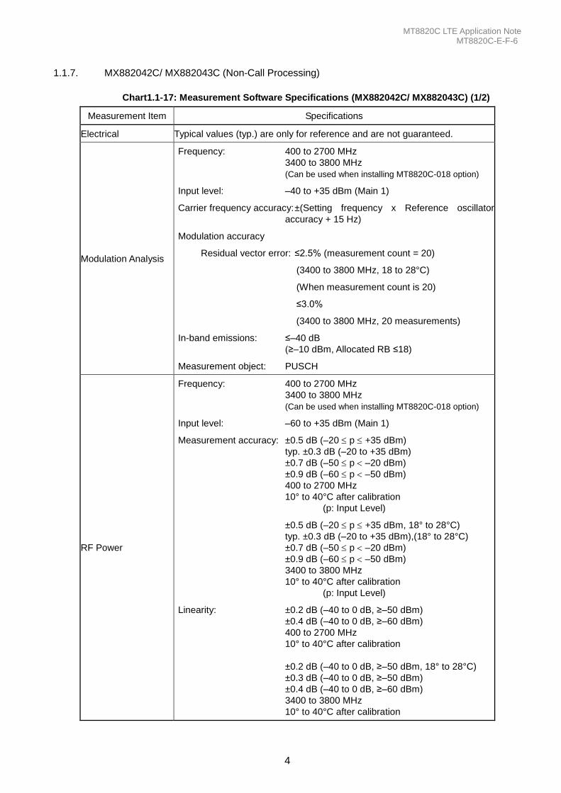
1.1.7. MX882042C/ MX882043C (Non-Call Processing)
Chart1.1-17: Measurement Software Specifications (MX882042C/ MX882043C) (1/2)
Measurement Item Specifications
Electrical Typical values (typ.) are only for reference and are not guaranteed.
Modulation Analysis
Frequency: 400 to 2700 MHz
3400 to 3800 MHz
(Can be used when installing MT8820C-018 option)
Input level: –40 to +35 dBm (Main 1)
Carrier frequency accuracy: ±(Setting frequency x Reference oscillator
accuracy + 15 Hz)
Modulation accuracy
Residual vector error: ≤2.5% (measurement count = 20)
(3400 to 3800 MHz, 18 to 28°C)
(When measurement count is 20)
≤3.0%
(3400 to 3800 MHz, 20 measurements)
In-band emissions: ≤–40 dB
(≥–10 dBm, Allocated RB ≤18)
Measurement object: PUSCH
RF Power
Frequency: 400 to 2700 MHz
3400 to 3800 MHz
(Can be used when installing MT8820C-018 option)
Input level: –60 to +35 dBm (Main 1)
Measurement accuracy: ±0.5 dB (–20 p +35 dBm)
typ. ±0.3 dB (–20 to +35 dBm)
±0.7 dB (–50 p –20 dBm)
±0.9 dB (–60 p –50 dBm)
400 to 2700 MHz
10° to 40°C after calibration
(p: Input Level)
±0.5 dB (–20 p +35 dBm, 18° to 28°C)
typ. ±0.3 dB (–20 to +35 dBm),(18° to 28°C)
±0.7 dB (–50 p –20 dBm)
±0.9 dB (–60 p –50 dBm)
3400 to 3800 MHz
10° to 40°C after calibration
(p: Input Level)
Linearity: ±0.2 dB (–40 to 0 dB, ≥–50 dBm)
±0.4 dB (–40 to 0 dB, ≥–60 dBm)
400 to 2700 MHz
10° to 40°C after calibration
±0.2 dB (–40 to 0 dB, ≥–50 dBm, 18° to 28°C)
±0.3 dB (–40 to 0 dB, ≥–50 dBm)
±0.4 dB (–40 to 0 dB, ≥–60 dBm)
3400 to 3800 MHz
10° to 40°C after calibration
MT8820C LTE Application Note MT8820C-E-F-6
5
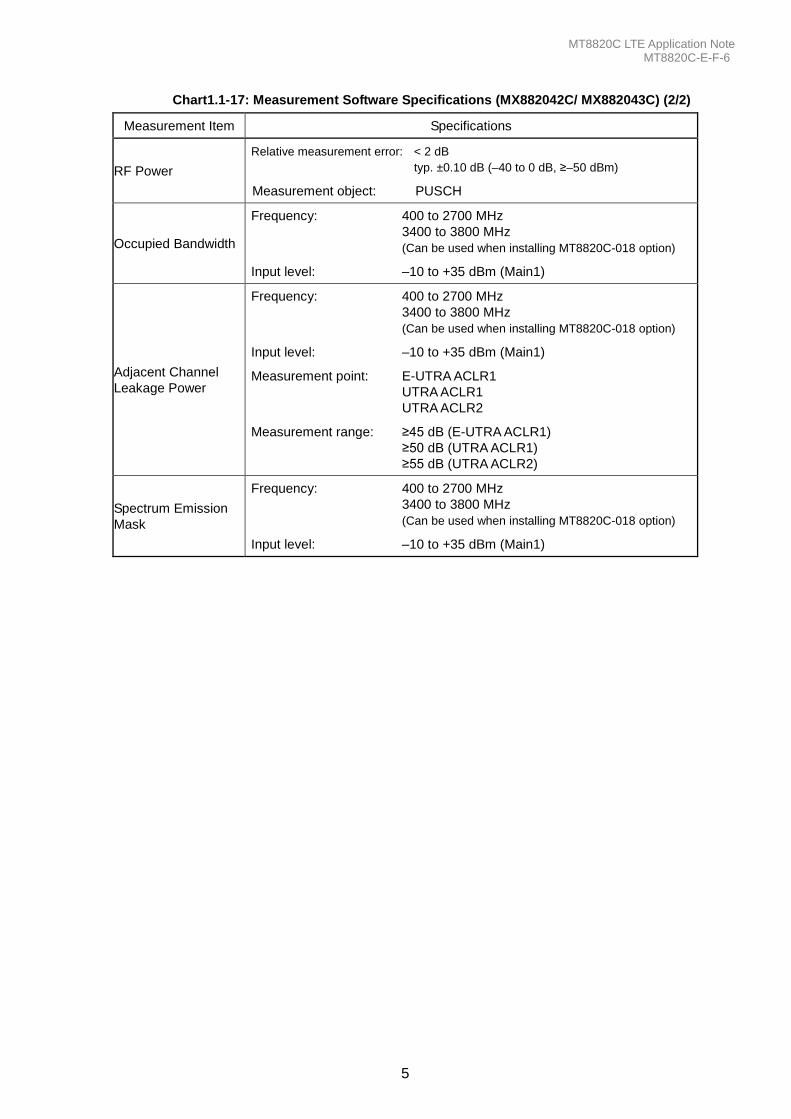
Chart1.1-17: Measurement Software Specifications (MX882042C/ MX882043C) (2/2)
Measurement Item Specifications
RF Power
Relative measurement error: < 2 dB
typ. ±0.10 dB (–40 to 0 dB, ≥–50 dBm)
Measurement object: PUSCH
Occupied Bandwidth
Frequency: 400 to 2700 MHz
3400 to 3800 MHz
(Can be used when installing MT8820C-018 option)
Input level: –10 to +35 dBm (Main1)
Adjacent Channel
Leakage Power
Frequency: 400 to 2700 MHz
3400 to 3800 MHz
(Can be used when installing MT8820C-018 option)
Input level: –10 to +35 dBm (Main1)
Measurement point: E-UTRA ACLR1
UTRA ACLR1
UTRA ACLR2
Measurement range: ≥45 dB (E-UTRA ACLR1)
≥50 dB (UTRA ACLR1)
≥55 dB (UTRA ACLR2)
Spectrum Emission
Mask
Frequency: 400 to 2700 MHz
3400 to 3800 MHz
(Can be used when installing MT8820C-018 option)
Input level: –10 to +35 dBm (Main1)
MT8820C LTE Application Note MT8820C-E-F-6
6
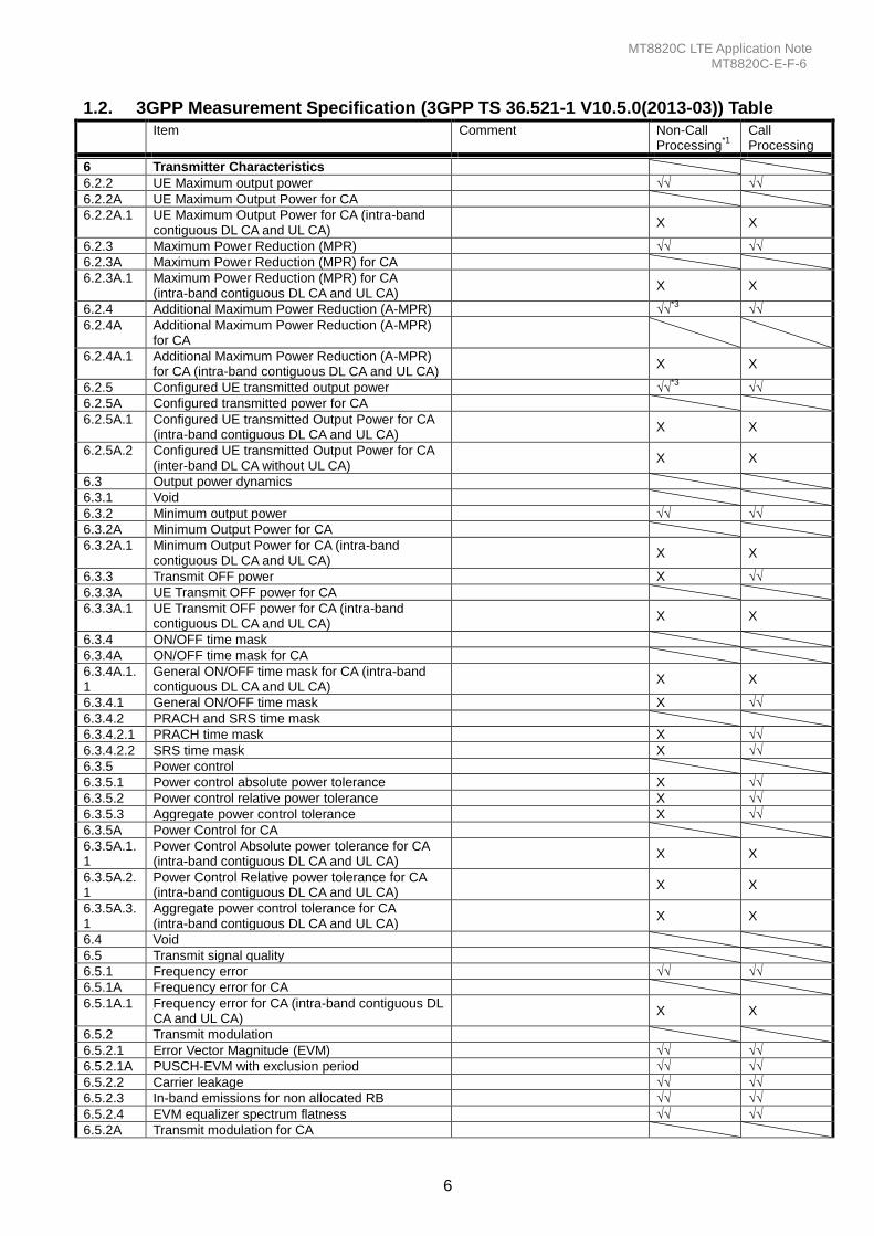
1.2. 3GPP Measurement Specification (3GPP TS 36.521-1 V10.5.0(2013-03)) Table
Item Comment Non-Call Processing
*1
Call Processing
6 Transmitter Characteristics
6.2.2 UE Maximum output power √√ √√
6.2.2A UE Maximum Output Power for CA
6.2.2A.1 UE Maximum Output Power for CA (intra-band contiguous DL CA and UL CA)
X X
6.2.3 Maximum Power Reduction (MPR) √√ √√
6.2.3A Maximum Power Reduction (MPR) for CA
6.2.3A.1 Maximum Power Reduction (MPR) for CA (intra-band contiguous DL CA and UL CA)
X X
6.2.4 Additional Maximum Power Reduction (A-MPR) √√*3
√√
6.2.4A Additional Maximum Power Reduction (A-MPR) for CA
6.2.4A.1 Additional Maximum Power Reduction (A-MPR) for CA (intra-band contiguous DL CA and UL CA)
X X
6.2.5 Configured UE transmitted output power √√*3
√√
6.2.5A Configured transmitted power for CA
6.2.5A.1 Configured UE transmitted Output Power for CA (intra-band contiguous DL CA and UL CA)
X X
6.2.5A.2 Configured UE transmitted Output Power for CA (inter-band DL CA without UL CA)
X X
6.3 Output power dynamics
6.3.1 Void
6.3.2 Minimum output power √√ √√
6.3.2A Minimum Output Power for CA
6.3.2A.1 Minimum Output Power for CA (intra-band contiguous DL CA and UL CA)
X X
6.3.3 Transmit OFF power X √√
6.3.3A UE Transmit OFF power for CA
6.3.3A.1 UE Transmit OFF power for CA (intra-band contiguous DL CA and UL CA)
X X
6.3.4 ON/OFF time mask
6.3.4A ON/OFF time mask for CA
6.3.4A.1.1
General ON/OFF time mask for CA (intra-band contiguous DL CA and UL CA)
X X
6.3.4.1 General ON/OFF time mask X √√
6.3.4.2 PRACH and SRS time mask
6.3.4.2.1 PRACH time mask X √√
6.3.4.2.2 SRS time mask X √√
6.3.5 Power control
6.3.5.1 Power control absolute power tolerance X √√
6.3.5.2 Power control relative power tolerance X √√
6.3.5.3 Aggregate power control tolerance X √√
6.3.5A Power Control for CA
6.3.5A.1.1
Power Control Absolute power tolerance for CA (intra-band contiguous DL CA and UL CA)
X X
6.3.5A.2.1
Power Control Relative power tolerance for CA (intra-band contiguous DL CA and UL CA)
X X
6.3.5A.3.1
Aggregate power control tolerance for CA (intra-band contiguous DL CA and UL CA)
X X
6.4 Void
6.5 Transmit signal quality
6.5.1 Frequency error √√ √√
6.5.1A Frequency error for CA
6.5.1A.1 Frequency error for CA (intra-band contiguous DL CA and UL CA)
X X
6.5.2 Transmit modulation
6.5.2.1 Error Vector Magnitude (EVM) √√ √√
6.5.2.1A PUSCH-EVM with exclusion period √√ √√
6.5.2.2 Carrier leakage √√ √√
6.5.2.3 In-band emissions for non allocated RB √√ √√
6.5.2.4 EVM equalizer spectrum flatness √√ √√
6.5.2A Transmit modulation for CA
MT8820C LTE Application Note MT8820C-E-F-6
7
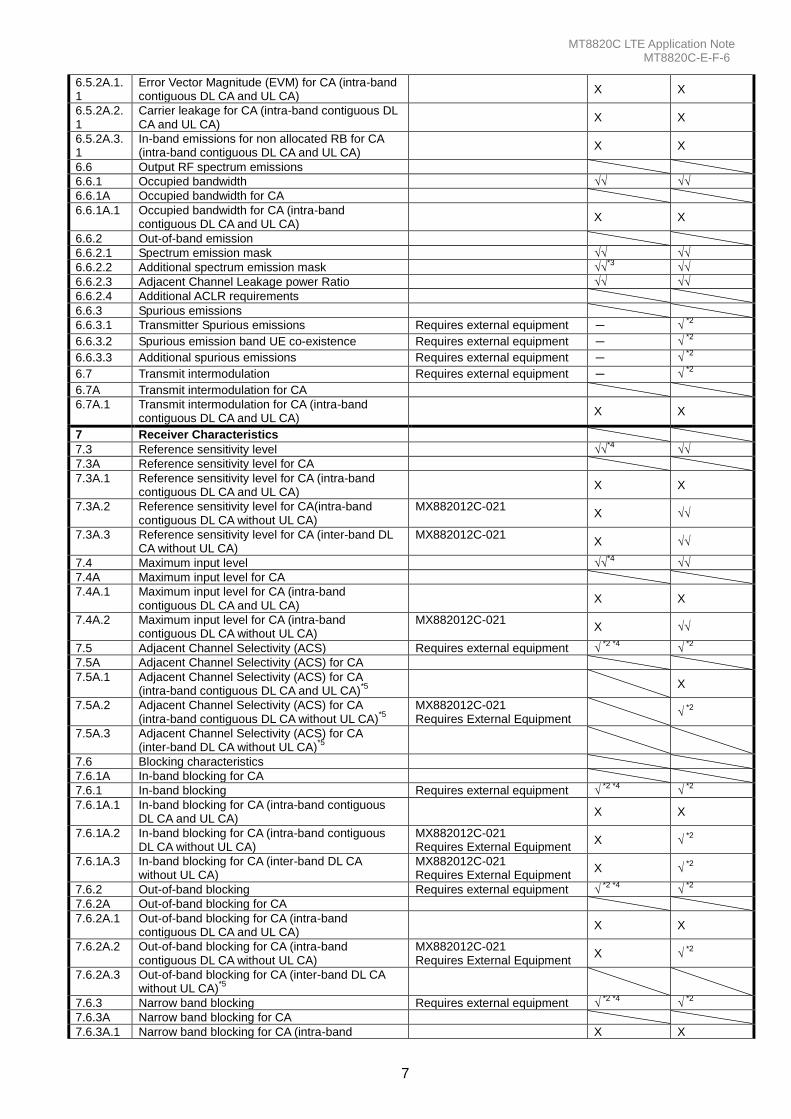
6.5.2A.1.1
Error Vector Magnitude (EVM) for CA (intra-band contiguous DL CA and UL CA)
X X
6.5.2A.2.1
Carrier leakage for CA (intra-band contiguous DL CA and UL CA)
X X
6.5.2A.3.1
In-band emissions for non allocated RB for CA (intra-band contiguous DL CA and UL CA)
X X
6.6 Output RF spectrum emissions
6.6.1 Occupied bandwidth √√ √√
6.6.1A Occupied bandwidth for CA
6.6.1A.1 Occupied bandwidth for CA (intra-band contiguous DL CA and UL CA)
X X
6.6.2 Out-of-band emission
6.6.2.1 Spectrum emission mask √√ √√
6.6.2.2 Additional spectrum emission mask √√*3
√√
6.6.2.3 Adjacent Channel Leakage power Ratio √√ √√
6.6.2.4 Additional ACLR requirements
6.6.3 Spurious emissions
6.6.3.1 Transmitter Spurious emissions Requires external equipment - √ *2
6.6.3.2 Spurious emission band UE co-existence Requires external equipment - √ *2
6.6.3.3 Additional spurious emissions Requires external equipment - √ *2
6.7 Transmit intermodulation Requires external equipment - √ *2
6.7A Transmit intermodulation for CA
6.7A.1 Transmit intermodulation for CA (intra-band contiguous DL CA and UL CA)
X X
7 Receiver Characteristics
7.3 Reference sensitivity level √√*4
√√
7.3A Reference sensitivity level for CA
7.3A.1 Reference sensitivity level for CA (intra-band contiguous DL CA and UL CA)
X X
7.3A.2 Reference sensitivity level for CA(intra-band contiguous DL CA without UL CA)
MX882012C-021 X √√
7.3A.3 Reference sensitivity level for CA (inter-band DL CA without UL CA)
MX882012C-021 X √√
7.4 Maximum input level √√*4
√√
7.4A Maximum input level for CA
7.4A.1 Maximum input level for CA (intra-band contiguous DL CA and UL CA)
X X
7.4A.2 Maximum input level for CA (intra-band contiguous DL CA without UL CA)
MX882012C-021 X √√
7.5 Adjacent Channel Selectivity (ACS) Requires external equipment √ *2 *4
√ *2
7.5A Adjacent Channel Selectivity (ACS) for CA
7.5A.1 Adjacent Channel Selectivity (ACS) for CA (intra-band contiguous DL CA and UL CA)
*5
X
7.5A.2 Adjacent Channel Selectivity (ACS) for CA (intra-band contiguous DL CA without UL CA)
*5
MX882012C-021 Requires External Equipment
√ *2
7.5A.3 Adjacent Channel Selectivity (ACS) for CA (inter-band DL CA without UL CA)
*5
7.6 Blocking characteristics
7.6.1A In-band blocking for CA
7.6.1 In-band blocking Requires external equipment √ *2 *4
√ *2
7.6.1A.1 In-band blocking for CA (intra-band contiguous DL CA and UL CA)
X X
7.6.1A.2 In-band blocking for CA (intra-band contiguous DL CA without UL CA)
MX882012C-021 Requires External Equipment
X √ *2
7.6.1A.3 In-band blocking for CA (inter-band DL CA without UL CA)
MX882012C-021 Requires External Equipment
X √ *2
7.6.2 Out-of-band blocking Requires external equipment √ *2 *4
√ *2
7.6.2A Out-of-band blocking for CA
7.6.2A.1 Out-of-band blocking for CA (intra-band contiguous DL CA and UL CA)
X X
7.6.2A.2 Out-of-band blocking for CA (intra-band contiguous DL CA without UL CA)
MX882012C-021 Requires External Equipment
X √ *2
7.6.2A.3 Out-of-band blocking for CA (inter-band DL CA without UL CA)
*5
7.6.3 Narrow band blocking Requires external equipment √ *2 *4
√ *2
7.6.3A Narrow band blocking for CA
7.6.3A.1 Narrow band blocking for CA (intra-band X X
MT8820C LTE Application Note MT8820C-E-F-6
8
contiguous DL CA and UL CA)
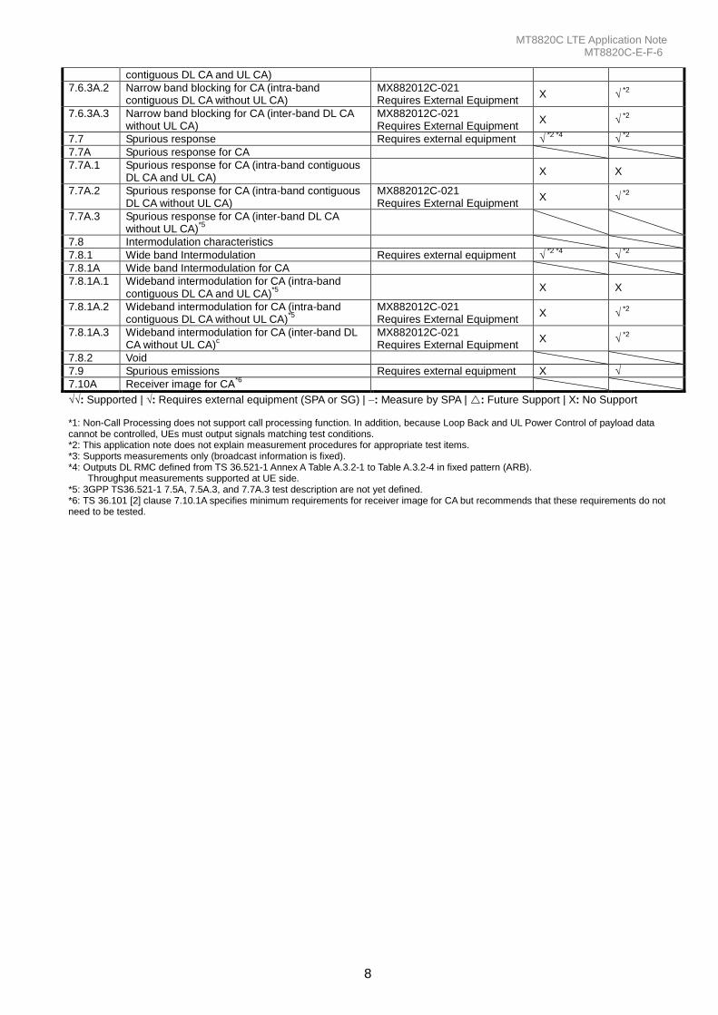
7.6.3A.2 Narrow band blocking for CA (intra-band contiguous DL CA without UL CA)
MX882012C-021 Requires External Equipment
X √ *2
7.6.3A.3 Narrow band blocking for CA (inter-band DL CA without UL CA)
MX882012C-021 Requires External Equipment
X √ *2
7.7 Spurious response Requires external equipment √ *2 *4
√ *2
7.7A Spurious response for CA
7.7A.1 Spurious response for CA (intra-band contiguous DL CA and UL CA)
X X
7.7A.2 Spurious response for CA (intra-band contiguous DL CA without UL CA)
MX882012C-021 Requires External Equipment
X √ *2
7.7A.3 Spurious response for CA (inter-band DL CA without UL CA)
*5
7.8 Intermodulation characteristics
7.8.1 Wide band Intermodulation Requires external equipment √ *2 *4
√ *2
7.8.1A Wide band Intermodulation for CA
7.8.1A.1 Wideband intermodulation for CA (intra-band contiguous DL CA and UL CA)
*5
X X
7.8.1A.2 Wideband intermodulation for CA (intra-band contiguous DL CA without UL CA)
*5
MX882012C-021 Requires External Equipment
X √ *2
7.8.1A.3 Wideband intermodulation for CA (inter-band DL CA without UL CA)
c
MX882012C-021 Requires External Equipment
X √ *2
7.8.2 Void
7.9 Spurious emissions Requires external equipment X √
7.10A Receiver image for CA*6
√√: Supported | √: Requires external equipment (SPA or SG) | : Measure by SPA | : Future Support | X: No Support *1: Non-Call Processing does not support call processing function. In addition, because Loop Back and UL Power Control of payload data cannot be controlled, UEs must output signals matching test conditions. *2: This application note does not explain measurement procedures for appropriate test items. *3: Supports measurements only (broadcast information is fixed). *4: Outputs DL RMC defined from TS 36.521-1 Annex A Table A.3.2-1 to Table A.3.2-4 in fixed pattern (ARB).
Throughput measurements supported at UE side. *5: 3GPP TS36.521-1 7.5A, 7.5A.3, and 7.7A.3 test description are not yet defined. *6: TS 36.101 [2] clause 7.10.1A specifies minimum requirements for receiver image for CA but recommends that these requirements do not need to be tested.
MT8820C LTE Application Note MT8820C-E-F-6
9
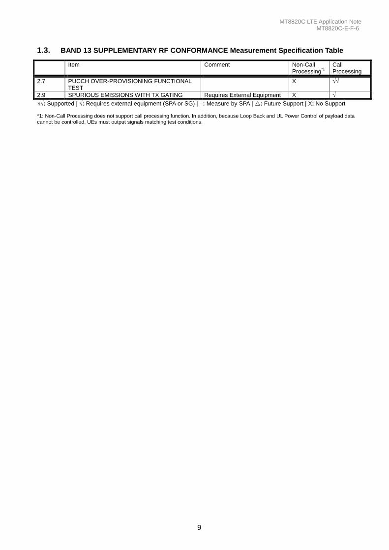
1.3. BAND 13 SUPPLEMENTARY RF CONFORMANCE Measurement Specification Table
Item Comment Non-Call Processing
*1
Call Processing
2.7 PUCCH OVER-PROVISIONING FUNCTIONAL TEST
X √√
2.9 SPURIOUS EMISSIONS WITH TX GATING Requires External Equipment X √
√√: Supported | √: Requires external equipment (SPA or SG) | : Measure by SPA | : Future Support | X: No Support *1: Non-Call Processing does not support call processing function. In addition, because Loop Back and UL Power Control of payload data cannot be controlled, UEs must output signals matching test conditions.
MT8820C LTE Application Note MT8820C-E-F-6
10
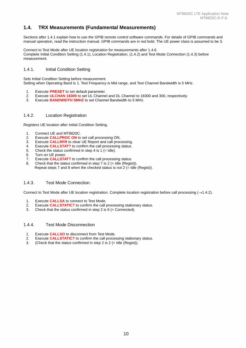
1.4. TRX Measurements (Fundamental Measurements) Sections after 1.4.1 explain how to use the GPIB remote control software commands. For details of GPIB commands and manual operation, read the instruction manual. GPIB commands are in red bold. The UE power class is assumed to be 3. Connect to Test Mode after UE location registration for measurements after 1.4.6. Complete Initial Condition Setting (1.4.1), Location Registration, (1.4.2) and Test Mode Connection (1.4.3) before measurement.
1.4.1. Initial Condition Setting Sets Initial Condition Setting before measurement. Setting when Operating Band is 1. Test Frequency is Mid range, and Test Channel Bandwidth is 5 MHz.
1. Execute PRESET to set default parameter. 2. Execute ULCHAN 18300 to set UL Channel and DL Channel to 18300 and 300, respectively. 3. Execute BANDWIDTH 5MHZ to set Channel Bandwidth to 5 MHz.
1.4.2. Location Registration Registers UE location after Initial Condition Setting.
1. Connect UE and MT8820C. 2. Execute CALLPROC ON to set call processing ON. 3. Execute CALLRFR to clear UE Report and call processing. 4. Execute CALLSTAT? to confirm the call processing status.
5. Check the status confirmed in step 4 is 1 (= Idle). 6. Turn on UE power. 7. Execute CALLSTAT? to confirm the call processing status.
8. Check that the status confirmed in step 7 is 2 (= Idle (Regist)). Repeat steps 7 and 8 when the checked status is not 2 (= Idle (Regist)).
1.4.3. Test Mode Connection.
Connect to Test Mode after UE location registration. Complete location registration before call processing (1.4.2).
1. Execute CALLSA to connect to Test Mode. 2. Execute CALLSTATIC? to confirm the call processing stationary status.
3. Check that the status confirmed in step 2 is 6 (= Connected).
1.4.4. Test Mode Disconnection
1. Execute CALLSO to disconnect from Test Mode. 2. Execute CALLSTATIC? to confirm the call processing stationary status.
3. (Check that the status confirmed in step 2 is 2 (= Idle (Regist)).
MT8820C LTE Application Note MT8820C-E-F-6
11
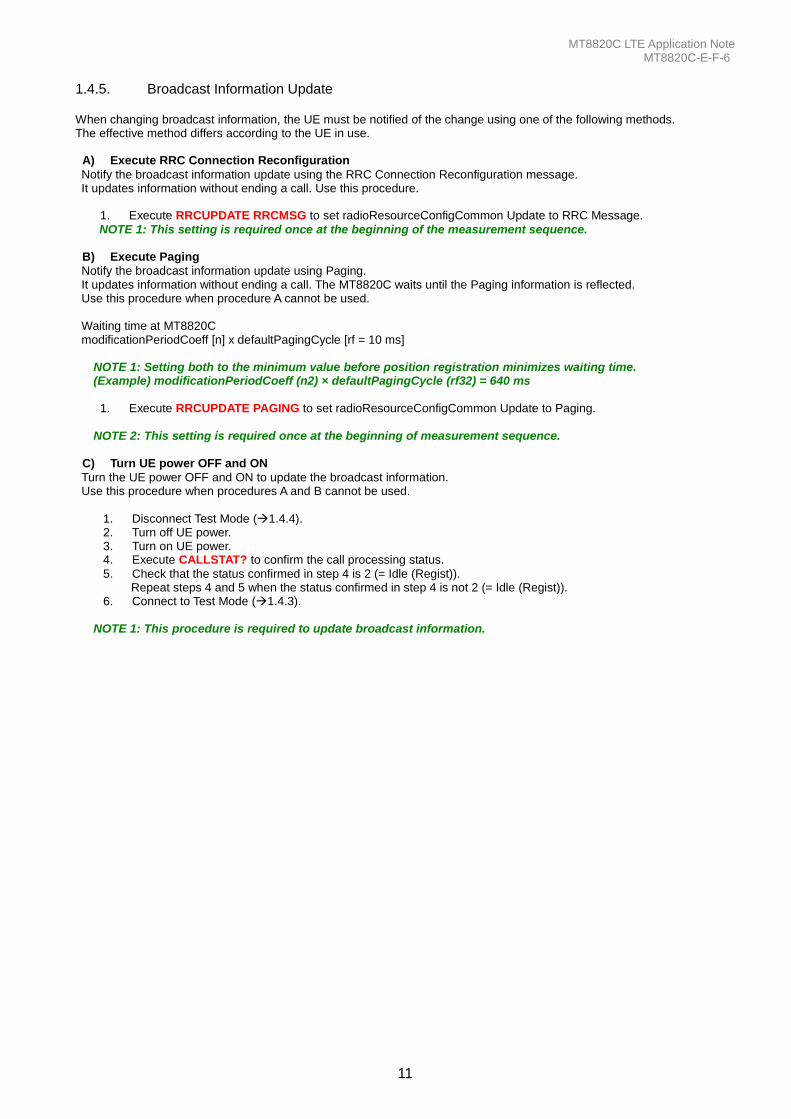
1.4.5. Broadcast Information Update When changing broadcast information, the UE must be notified of the change using one of the following methods. The effective method differs according to the UE in use.
A) Execute RRC Connection Reconfiguration
Notify the broadcast information update using the RRC Connection Reconfiguration message. It updates information without ending a call. Use this procedure.
1. Execute RRCUPDATE RRCMSG to set radioResourceConfigCommon Update to RRC Message.
NOTE 1: This setting is required once at the beginning of the measurement sequence. B) Execute Paging
Notify the broadcast information update using Paging. It updates information without ending a call. The MT8820C waits until the Paging information is reflected. Use this procedure when procedure A cannot be used. Waiting time at MT8820C modificationPeriodCoeff [n] x defaultPagingCycle [rf = 10 ms]
NOTE 1: Setting both to the minimum value before position registration minimizes waiting time. (Example) modificationPeriodCoeff (n2) × defaultPagingCycle (rf32) = 640 ms
1. Execute RRCUPDATE PAGING to set radioResourceConfigCommon Update to Paging.
NOTE 2: This setting is required once at the beginning of measurement sequence.
C) Turn UE power OFF and ON
Turn the UE power OFF and ON to update the broadcast information. Use this procedure when procedures A and B cannot be used.
1. Disconnect Test Mode (1.4.4). 2. Turn off UE power. 3. Turn on UE power. 4. Execute CALLSTAT? to confirm the call processing status.
5. Check that the status confirmed in step 4 is 2 (= Idle (Regist)). Repeat steps 4 and 5 when the status confirmed in step 4 is not 2 (= Idle (Regist)).
6. Connect to Test Mode (1.4.3).
NOTE 1: This procedure is required to update broadcast information.
MT8820C LTE Application Note MT8820C-E-F-6
12
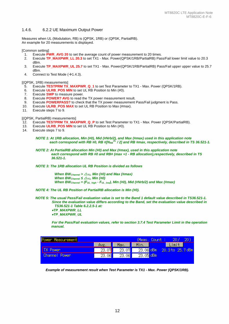
1.4.6. 6.2.2 UE Maximum Output Power Measures when UL (Modulation, RB) is (QPSK, 1RB) or (QPSK, PartialRB). An example for 20 measurements is displayed. [Common setting]
1. Execute PWR_AVG 20 to set the average count of power measurement to 20 times. 2. Execute TP_MAXPWR_LL 20.3 to set TX1 - Max. Power(QPSK/1RB/PartialRB) Pass/Fail lower limit value to 20.3
dBm. 3. Execute TP_MAXPWR_UL 25.7 to set TX1 - Max. Power(QPSK/1RB/PartialRB) Pass/Fail upper upper value to 25.7
dBm. 4. Connect to Test Mode (1.4.3).
[(QPSK, 1RB) measurements]
5. Execute TESTPRM TX_MAXPWR_Q_1 to set Test Parameter to TX1 - Max. Power (QPSK/1RB). 6. Execute ULRB_POS MIN to set UL RB Position to Min (#0). 7. Execute SWP to measure power. 8. Execute POWER? AVG to read the TX power measurement result. 9. Execute POWERPASS? to check that the TX power measurement Pass/Fail judgment is Pass.
10. Execute ULRB_POS MAX to set UL RB Position to Max (#max).
11. Execute steps 7 to 9. [(QPSK, PartialRB) measurements] 12. Execute TESTPRM TX_MAXPWR_Q_P to set Test Parameter to TX1 - Max. Power (QPSK/PartialRB). 13. Execute ULRB_POS MIN to set UL RB Position to Min (#0).
14. Execute steps 7 to 9.
NOTE 1: At 1RB allocation, Min (#0), Mid (#Nrb/2), and Max (#max) used in this application note each correspond with RB #0, RB #[NRB
UL / 2] and RB #max, respectively, described in TS 36.521-1.
NOTE 2: At PartialRB allocation Min (#0) and Max (#max), used in this application note
each correspond with RB #0 and RB# (max +1 - RB allocation),respectively, described in TS 36.521-1.
NOTE 3: The 1RB allocation UL RB Position is divided as follows
When BWChannel > TC, Min (#0) and Max (#max) When BWChannel ≤ TC, Min (#0) When BWChannel = (FUL_high - FUL_low), Min (#0), Mid (#Nrb/2) and Max (#max)
NOTE 4: The UL RB Position of PartialRB allocation is Min (#0). NOTE 5: The usual Pass/Fail evaluation value is set to the Band 1 default value described in TS36.521-1.
Since the evaluation value differs according to the Band, set the evaluation value described in TS36.521-1 Table 6.2.2.5-1 at:
TP_MAXPWR_LL
TP_MAXPWR_UL For the Pass/Fail evaluation values, refer to section 3.7.4 Test Parameter Limit in the operation manual.
Example of measurement result when Test Parameter is TX1 - Max. Power (QPSK/1RB).
MT8820C LTE Application Note MT8820C-E-F-6
13
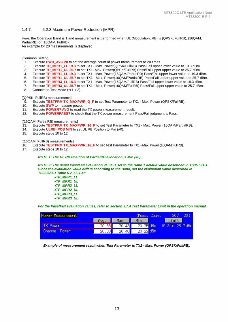
1.4.7. 6.2.3 Maximum Power Reduction (MPR) Here, the Operation Band is 1 and measurement is performed when UL (Modulation, RB) is (QPSK, FullRB), (16QAM, PartialRB) or (16QAM, FullRB). An example for 20 measurements is displayed. [Common Setting]
1. Execute PWR_AVG 20 to set the average count of power measurement to 20 times. 2. Execute TP_MPR1_LL 19.3 to set TX1 - Max. Power(QPSK/FullRB) Pass/Fail upper lower value to 19.3 dBm. 3. Execute TP_MPR1_UL 25.7 to set TX1- Max. Power(QPSK/FullRB) Pass/Fail upper upper value to 25.7 dBm. 4. Execute TP_MPR1_LL 19.3 to set TX1 - Max. Power(16QAM/PartialRB) Pass/Fail upper lower value to 19.3 dBm. 5. Execute TP_MPR1_UL 25.7 to set TX1 - Max. Power(16QAM/PartialRB) Pass/Fail upper upper value to 25.7 dBm. 6. Execute TP_MPR3_LL 18.3 to set TX1 - Max. Power(16QAM/FullRB) Pass/Fail upper lower value to 18.3 dBm. 7. Execute TP_MPR3_UL 25.7 to set TX1 - Max. Power(16QAM/FullRB) Pass/Fail upper upper value to 25.7 dBm.
8. Connect to Test Mode (1.4.3). [(QPSK, FullRB) measurements]
9. Execute TESTPRM TX_MAXPWR_Q_F to set Test Parameter to TX1 - Max. Power (QPSK/FullRB). 10. Execute SWP to measure power. 11. Execute POWER? AVG to read the TX power measurement result. 12. Execute POWERPASS? to check that the TX power measurement Pass/Fail judgment is Pass.
[(16QAM, PartialRB) measurements] 13. Execute TESTPRM TX_MAXPWR_16_P to set Test Parameter to TX1 - Max. Power (16QAM/PartialRB). 14. Execute ULRB_POS MIN to set UL RB Position to Min (#0).
15. Execute steps 10 to 12. [(16QAM, FullRB) measurements] 16. Execute TESTPRM TX_MAXPWR_16_F to set Test Parameter to TX1 - Max. Power (16QAM/FullRB).
17. Execute steps 10 to 12. NOTE 1: The UL RB Position of PartialRB allocation is Min (#0).
NOTE 2: The usual Pass/Fail evaluation value is set to the Band 1 default value described in TS36.521-1. Since the evaluation value differs according to the Band, set the evaluation value described in TS36.521-1 Table 6.2.3.5-1 at:
TP_MPR1_LL
TP_MPR1_UL
TP_MPR2_LL
TP_MPR2_UL
TP_MPR3_LL
TP_MPR3_UL
For the Pass/Fail evaluation values, refer to section 3.7.4 Test Parameter Limit in the operation manual.
Example of measurement result when Test Parameter is TX1 - Max. Power (QPSK/FullRB).
MT8820C LTE Application Note MT8820C-E-F-6
14
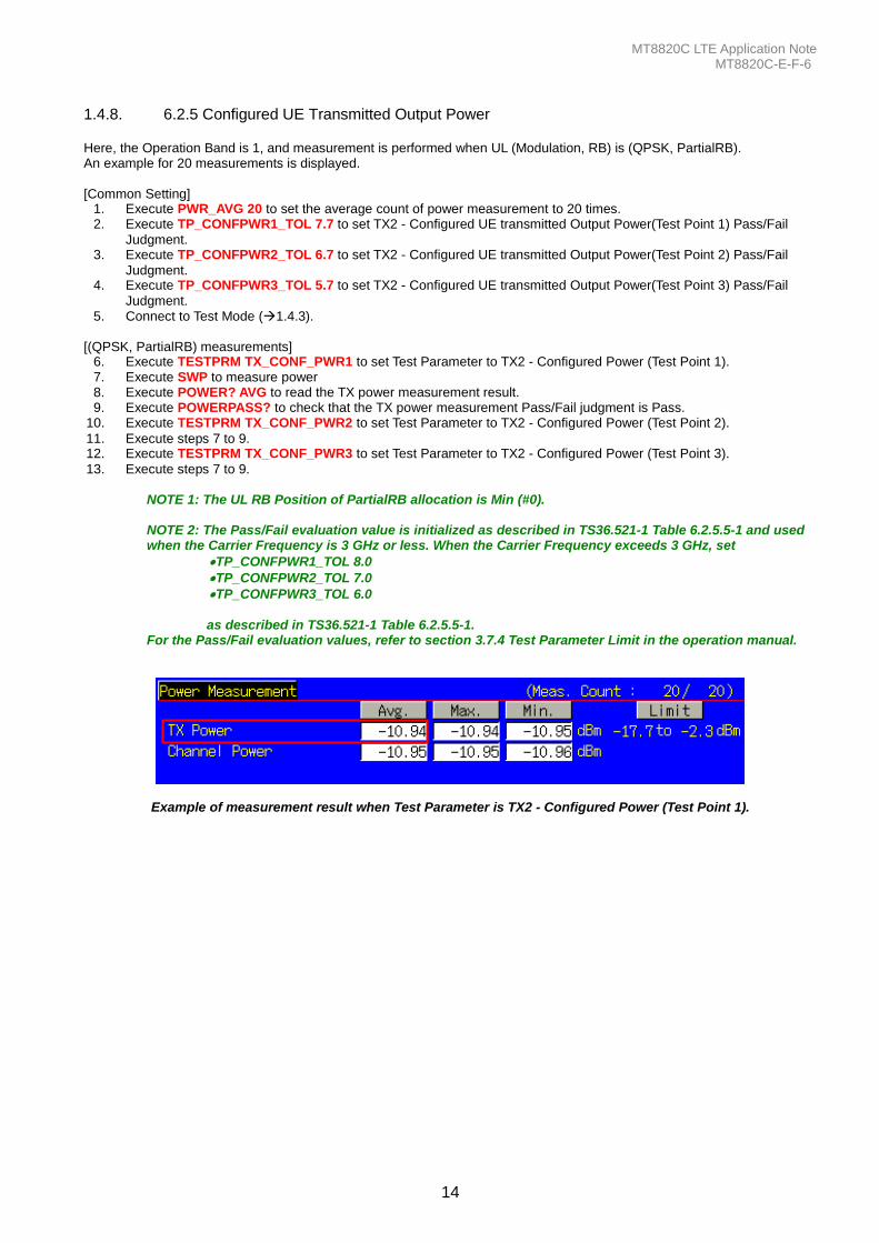
1.4.8. 6.2.5 Configured UE Transmitted Output Power Here, the Operation Band is 1, and measurement is performed when UL (Modulation, RB) is (QPSK, PartialRB). An example for 20 measurements is displayed. [Common Setting]
1. Execute PWR_AVG 20 to set the average count of power measurement to 20 times. 2. Execute TP_CONFPWR1_TOL 7.7 to set TX2 - Configured UE transmitted Output Power(Test Point 1) Pass/Fail
Judgment. 3. Execute TP_CONFPWR2_TOL 6.7 to set TX2 - Configured UE transmitted Output Power(Test Point 2) Pass/Fail
Judgment. 4. Execute TP_CONFPWR3_TOL 5.7 to set TX2 - Configured UE transmitted Output Power(Test Point 3) Pass/Fail
Judgment. 5. Connect to Test Mode (1.4.3).
[(QPSK, PartialRB) measurements]
6. Execute TESTPRM TX_CONF_PWR1 to set Test Parameter to TX2 - Configured Power (Test Point 1). 7. Execute SWP to measure power 8. Execute POWER? AVG to read the TX power measurement result. 9. Execute POWERPASS? to check that the TX power measurement Pass/Fail judgment is Pass.
10. Execute TESTPRM TX_CONF_PWR2 to set Test Parameter to TX2 - Configured Power (Test Point 2).
11. Execute steps 7 to 9. 12. Execute TESTPRM TX_CONF_PWR3 to set Test Parameter to TX2 - Configured Power (Test Point 3).
13. Execute steps 7 to 9. NOTE 1: The UL RB Position of PartialRB allocation is Min (#0). NOTE 2: The Pass/Fail evaluation value is initialized as described in TS36.521-1 Table 6.2.5.5-1 and used when the Carrier Frequency is 3 GHz or less. When the Carrier Frequency exceeds 3 GHz, set
TP_CONFPWR1_TOL 8.0
TP_CONFPWR2_TOL 7.0
TP_CONFPWR3_TOL 6.0 as described in TS36.521-1 Table 6.2.5.5-1.
For the Pass/Fail evaluation values, refer to section 3.7.4 Test Parameter Limit in the operation manual.
Example of measurement result when Test Parameter is TX2 - Configured Power (Test Point 1).
MT8820C LTE Application Note MT8820C-E-F-6
15
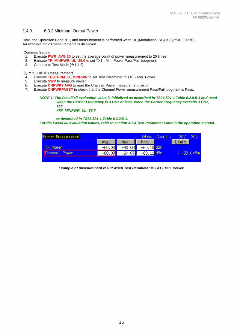
1.4.9. 6.3.2 Minimum Output Power Here, the Operation Band is 1, and measurement is performed when UL (Modulation, RB) is (QPSK, FullRB). An example for 20 measurements is displayed. [Common Setting]
1. Execute PWR_AVG 20 to set the average count of power measurement to 20 times. 2. Execute TP_MINPWR_UL -39.0 to set TX1 - Min. Power Pass/Fail Judgment.
3. Connect to Test Mode (1.4.3). [(QPSK, FullRB) measurements]
4. Execute TESTPRM TX_MINPWR to set Test Parameter to TX1 - Min. Power. 5. Execute SWP to measure power. 6. Execute CHPWR? AVG to read the Channel Power measurement result. 7. Execute CHPWRPASS? to check that the Channel Power measurement Pass/Fail judgment is Pass.
NOTE 1: The Pass/Fail evaluation value is initialized as described in TS36.521-1 Table 6.2.5.5-1 and used when the Carrier Frequency is 3 GHz or less. When the Carrier Frequency exceeds 3 GHz, set:
TP_MINPWR_UL -38.7 as described in TS36.521-1 Table 6.3.2.5-1.
For the Pass/Fail evaluation values, refer to section 3.7.4 Test Parameter Limit in the operation manual.
Example of measurement result when Test Parameter is TX1 - Min. Power.
MT8820C LTE Application Note MT8820C-E-F-6
16
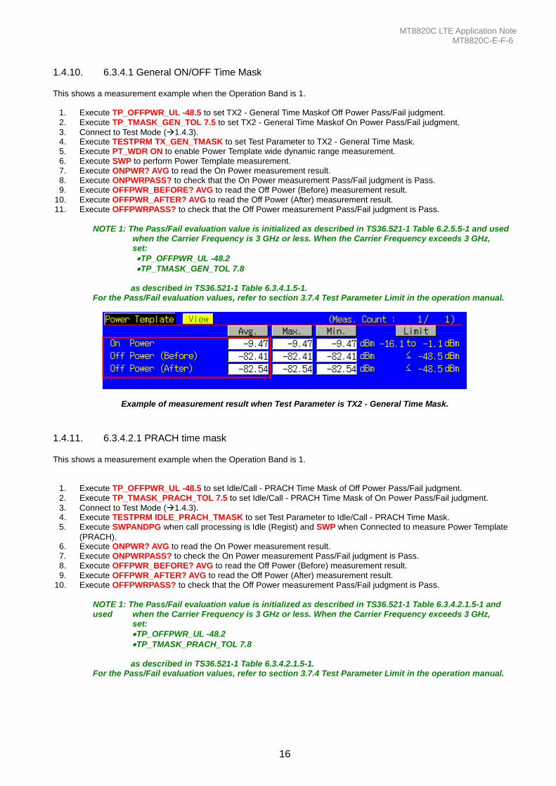
1.4.10. 6.3.4.1 General ON/OFF Time Mask This shows a measurement example when the Operation Band is 1.
1. Execute TP_OFFPWR_UL -48.5 to set TX2 - General Time Maskof Off Power Pass/Fail judgment. 2. Execute TP_TMASK_GEN_TOL 7.5 to set TX2 - General Time Maskof On Power Pass/Fail judgment.
3. Connect to Test Mode (1.4.3). 4. Execute TESTPRM TX_GEN_TMASK to set Test Parameter to TX2 - General Time Mask. 5. Execute PT_WDR ON to enable Power Template wide dynamic range measurement. 6. Execute SWP to perform Power Template measurement. 7. Execute ONPWR? AVG to read the On Power measurement result. 8. Execute ONPWRPASS? to check that the On Power measurement Pass/Fail judgment is Pass. 9. Execute OFFPWR_BEFORE? AVG to read the Off Power (Before) measurement result.
10. Execute OFFPWR_AFTER? AVG to read the Off Power (After) measurement result. 11. Execute OFFPWRPASS? to check that the Off Power measurement Pass/Fail judgment is Pass.
NOTE 1: The Pass/Fail evaluation value is initialized as described in TS36.521-1 Table 6.2.5.5-1 and used when the Carrier Frequency is 3 GHz or less. When the Carrier Frequency exceeds 3 GHz, set:
TP_OFFPWR_UL -48.2
TP_TMASK_GEN_TOL 7.8 as described in TS36.521-1 Table 6.3.4.1.5-1.
For the Pass/Fail evaluation values, refer to section 3.7.4 Test Parameter Limit in the operation manual.
Example of measurement result when Test Parameter is TX2 - General Time Mask.
1.4.11. 6.3.4.2.1 PRACH time mask This shows a measurement example when the Operation Band is 1.
1. Execute TP_OFFPWR_UL -48.5 to set Idle/Call - PRACH Time Mask of Off Power Pass/Fail judgment. 2. Execute TP_TMASK_PRACH_TOL 7.5 to set Idle/Call - PRACH Time Mask of On Power Pass/Fail judgment.
3. Connect to Test Mode (1.4.3). 4. Execute TESTPRM IDLE_PRACH_TMASK to set Test Parameter to Idle/Call - PRACH Time Mask. 5. Execute SWPANDPG when call processing is Idle (Regist) and SWP when Connected to measure Power Template
(PRACH). 6. Execute ONPWR? AVG to read the On Power measurement result. 7. Execute ONPWRPASS? to check the On Power measurement Pass/Fail judgment is Pass. 8. Execute OFFPWR_BEFORE? AVG to read the Off Power (Before) measurement result. 9. Execute OFFPWR_AFTER? AVG to read the Off Power (After) measurement result.
10. Execute OFFPWRPASS? to check that the Off Power measurement Pass/Fail judgment is Pass.
NOTE 1: The Pass/Fail evaluation value is initialized as described in TS36.521-1 Table 6.3.4.2.1.5-1 and used when the Carrier Frequency is 3 GHz or less. When the Carrier Frequency exceeds 3 GHz, set:
TP_OFFPWR_UL -48.2
TP_TMASK_PRACH_TOL 7.8 as described in TS36.521-1 Table 6.3.4.2.1.5-1.
For the Pass/Fail evaluation values, refer to section 3.7.4 Test Parameter Limit in the operation manual.

MT8820C LTE Application Note MT8820C-E-F-6
17
Example of measurement result when Test Parameter is Idle/Call - PRACH Time Mask.
MT8820C LTE Application Note MT8820C-E-F-6
18
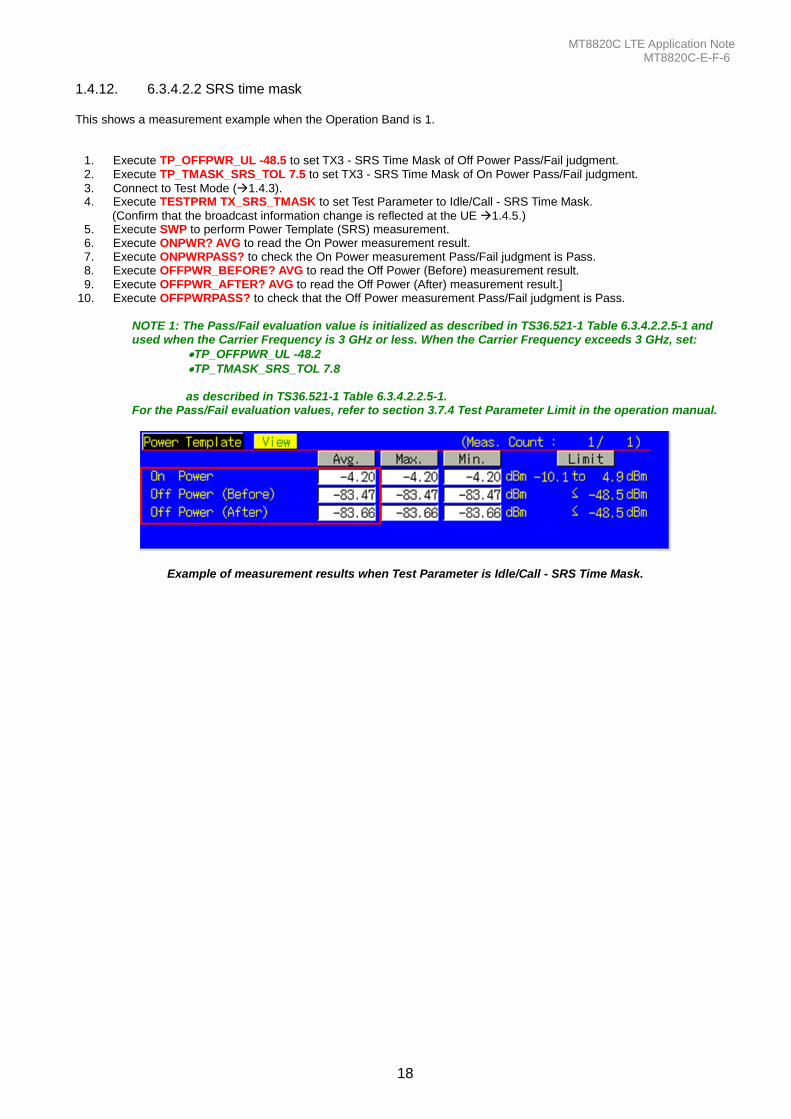
1.4.12. 6.3.4.2.2 SRS time mask This shows a measurement example when the Operation Band is 1.
1. Execute TP_OFFPWR_UL -48.5 to set TX3 - SRS Time Mask of Off Power Pass/Fail judgment. 2. Execute TP_TMASK_SRS_TOL 7.5 to set TX3 - SRS Time Mask of On Power Pass/Fail judgment.
3. Connect to Test Mode (1.4.3). 4. Execute TESTPRM TX_SRS_TMASK to set Test Parameter to Idle/Call - SRS Time Mask.
(Confirm that the broadcast information change is reflected at the UE 1.4.5.) 5. Execute SWP to perform Power Template (SRS) measurement. 6. Execute ONPWR? AVG to read the On Power measurement result. 7. Execute ONPWRPASS? to check the On Power measurement Pass/Fail judgment is Pass. 8. Execute OFFPWR_BEFORE? AVG to read the Off Power (Before) measurement result. 9. Execute OFFPWR_AFTER? AVG to read the Off Power (After) measurement result.]
10. Execute OFFPWRPASS? to check that the Off Power measurement Pass/Fail judgment is Pass.
NOTE 1: The Pass/Fail evaluation value is initialized as described in TS36.521-1 Table 6.3.4.2.2.5-1 and used when the Carrier Frequency is 3 GHz or less. When the Carrier Frequency exceeds 3 GHz, set:
TP_OFFPWR_UL -48.2
TP_TMASK_SRS_TOL 7.8 as described in TS36.521-1 Table 6.3.4.2.2.5-1.
For the Pass/Fail evaluation values, refer to section 3.7.4 Test Parameter Limit in the operation manual.
Example of measurement results when Test Parameter is Idle/Call - SRS Time Mask.

MT8820C LTE Application Note MT8820C-E-F-6
19
1.4.13. 6.3.5.1 Power Control Absolute Power Tolerance This shows a measurement example for Normal Conditions when the Operation Band is 1. 1. Connect to Test Mode(1.4.3) 2. Execute TESTPRM TX_PCTABS1 to set Test Parameter to TX3 - Absolute Power (Test Point1). 3. Execute SWP to perform Power Control Tolerance (Absolute Power) measurement. 4. Execute PCTPWR? to read the Absolute Power (dBm) measurement result. 5. Execute PCTPASS? to check that the Absolute Power measurement Pass/Fail judgment is Pass. 6. Execute TESTPRM TX_PCTABS2 to set Test Parameter to TX3 - Absolute Power (Test Point2).
7. Execute steps 3 to 5.
NOTE 1: The Pass/Fail evaluation value is initialized as described in TS36.521-1 Table 6.3.5.1.5-1 and used when the Carrier Frequency is 3 GHz or less. When the Carrier Frequency exceeds 3 GHz, set:
TP_PCTABS_TOL 10.4 as described in TS36.521-1 Table 6.3.5.1.5-1.
For the Pass/Fail evaluation values, refer to section 3.7.4 Test Parameter Limit in the operation manual.
Example of measurement result when Test Parameter is TX3 - Absolute Power(Test Point1).
1.4.14. 6.3.5.2 Power Control Relative Power Tolerance
1. Connect to Test Mode (1.4.3). 2. Execute TESTPRM TX_PCTREL_UP_A to set Test Parameter to TX3 - Relative Power (Ramping UP A). 3. Execute SWP to perform Power Control Tolerance (Relative Power) measurement. 4. Execute PCTPWR? to read the Relative Power (dB) measurement result. 5. Execute PCTPASS? to check that the Relative Power measurement Pass/Fail judgment is Pass. 6. Execute TESTPRM TX_PCTREL_UP_B to set Test Parameter to TX3 - Relative Power (Ramping UP B).
7. Execute steps 3 to 5. 8. Execute TESTPRM TX_PCTREL_UP_C to set Test Parameter to TX3 - Relative Power (Ramping UP C).
9. Execute steps 3 to 5. 10. Execute TESTPRM TX_PCTREL_DOWN_A to set Test Parameter to TX3 - Relative Power (Ramping Down A).
11. Execute steps 3 to 5. 12. TESTPRM TX_PCTREL_DOWN_B to set Test Parameter to TX3 - Relative Power (Ramping Down B).
13. Execute steps 3 to 5. 14. TESTPRM TX_PCTREL_DOWN_C to set Test Parameter to TX3 - Relative Power (Ramping Down C).
15. Execute steps 3 to 5. 16. TESTPRM TX_PCTREL_ALT to set Test Parameter to TX3 - Relative Power (Alternating).
17. Execute steps 3 to 5.
Example of measurement result when Test Parameter is TX3 - Relative Power (Sub-test A).
MT8820C LTE Application Note MT8820C-E-F-6
20
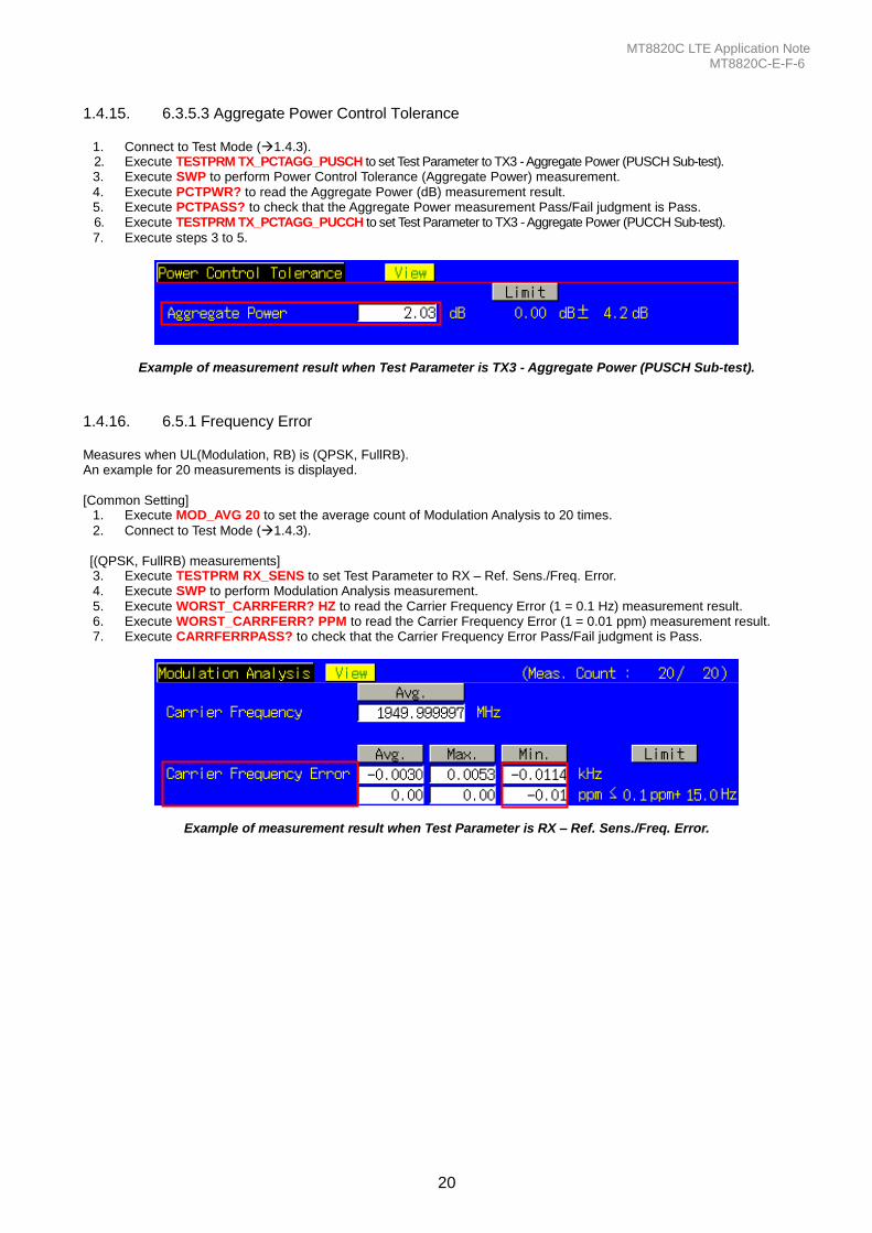
1.4.15. 6.3.5.3 Aggregate Power Control Tolerance
1. Connect to Test Mode (1.4.3). 2. Execute TESTPRM TX_PCTAGG_PUSCH to set Test Parameter to TX3 - Aggregate Power (PUSCH Sub-test). 3. Execute SWP to perform Power Control Tolerance (Aggregate Power) measurement. 4. Execute PCTPWR? to read the Aggregate Power (dB) measurement result. 5. Execute PCTPASS? to check that the Aggregate Power measurement Pass/Fail judgment is Pass. 6. Execute TESTPRM TX_PCTAGG_PUCCH to set Test Parameter to TX3 - Aggregate Power (PUCCH Sub-test).
7. Execute steps 3 to 5.
Example of measurement result when Test Parameter is TX3 - Aggregate Power (PUSCH Sub-test).
1.4.16. 6.5.1 Frequency Error Measures when UL(Modulation, RB) is (QPSK, FullRB). An example for 20 measurements is displayed. [Common Setting]
1. Execute MOD_AVG 20 to set the average count of Modulation Analysis to 20 times.
2. Connect to Test Mode (1.4.3). [(QPSK, FullRB) measurements]
3. Execute TESTPRM RX_SENS to set Test Parameter to RX – Ref. Sens./Freq. Error. 4. Execute SWP to perform Modulation Analysis measurement. 5. Execute WORST_CARRFERR? HZ to read the Carrier Frequency Error (1 = 0.1 Hz) measurement result. 6. Execute WORST_CARRFERR? PPM to read the Carrier Frequency Error (1 = 0.01 ppm) measurement result. 7. Execute CARRFERRPASS? to check that the Carrier Frequency Error Pass/Fail judgment is Pass.
Example of measurement result when Test Parameter is RX – Ref. Sens./Freq. Error.
MT8820C LTE Application Note MT8820C-E-F-6
21
1.4.17. 6.5.2.1 Error Vector Magnitude (EVM) - PUSCH Measures when UL (Modulation, RB) is (QPSK, PartialRB), (QPSK, FullRB), (16QAM, PartialRB) or (16QAM, FullRB). An example for 20 measurements is displayed. [Common Setting]
1. Execute MOD_AVG 20 to set the average count of Modulation Analysis to 20 times.
2. Connect to Test Mode (1.4.3). [(QPSK, PartialRB) measurements]
3. Execute TESTPRM TX_MAXPWR_Q_P to set Test Parameter to TX1 - Max. Power (QPSK/PartialRB). 4. Execute ULRB_POS MIN to set UL RB Position to Min (#0). 5. Execute SWP to perform Modulation Analysis measurement. 6. Execute EVM? AVG to read the EVM measurement result. 7. Execute EVMPASS? to check that the EVM Pass/Fail judgment is Pass. 8. Execute RSEVM? AVG to read the Reference Signal EVM measurement result. 9. Execute RSEVMPASS? to check that the Reference Signal EVM Pass/Fail judgment is Pass.
10. Execute ULRB_POS MAX to set the UL RB Position to Max (#max).
11. Execute steps 5 to 9. 12. Execute TESTPRM TX_M40DBM_Q_P to set Test Parameter to TX1 - EVM/IBE/LEAK @ -40 dBm (QPSK/PartialRB)
13. Execute steps 4 to 11. [(QPSK, FullRB) measurements] 14. Execute TESTPRM TX_MAXPWR_Q_F to set Test Parameter to TX1 - Max. Power (QPSK/FullRB).
15. Execute steps 5 to 9. 16. Execute TESTPRM TX_M40DBM_Q_F to set Test Parameter to TX1 - EVM @ -40 dBm (QPSK/Full RB).
17. Execute steps 5 to 9. [(16QAM, PartialRB) measurements] 18. Execute TESTPRM TX_MAXPWR_16_P to set Test Parameter to TX1 - Max. Power (16QAM/PartialRB).
19. Execute steps 4 to 11. 20. Execute TESTPRM TX_M40DBM_16_P to set Test Parameter to TX1 - EVM @ -40 dBm (16QAM/Partial RB).
21. Execute steps 4 to 11. [(16QAM, FullRB) measurements] 22. Execute TESTPRM TX_MAXPWR_16_F to set Test Parameter to TX1 - Max. Power (16QAM/FullRB).
23. Execute steps 5 to 9. 24. Execute TESTPRM TX_M40DBM_16_F to set Test Parameter to TX1 - EVM @ -40 dBm (16QAM/Full RB).
25. Execute steps 5 to 9. NOTE 1: The UL RB Position of PartialRB allocation is Min (#0) or Max (#max).
MT8820C LTE Application Note MT8820C-E-F-6
22
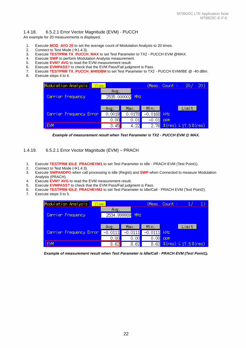
1.4.18. 6.5.2.1 Error Vector Magnitude (EVM) - PUCCH An example for 20 measurements is displayed.
1. Execute MOD_AVG 20 to set the average count of Modulation Analysis to 20 times.
2. Connect to Test Mode (1.4.3). 3. Execute TESTPRM TX_PUCCH_MAX to set Test Parameter to TX2 - PUCCH EVM @MAX. 4. Execute SWP to perform Modulation Analysis measurement. 5. Execute EVM? AVG to read the EVM measurement result. 6. Execute EVMPASS? to check that the EVM Pass/Fail judgment is Pass. 7. Execute TESTPRM TX_PUCCH_M40DBM to set Test Parameter to TX2 - PUCCH EVM/IBE @ -40 dBm.
8. Execute steps 4 to 6.
Example of measurement result when Test Parameter is TX2 - PUCCH EVM @ MAX.
1.4.19. 6.5.2.1 Error Vector Magnitude (EVM) – PRACH
1. Execute TESTPRM IDLE_PRACHEVM1 to set Test Parameter to Idle - PRACH EVM (Test Point1).
2. Connect to Test Mode (1.4.3). 3. Execute SWPANDPG when call processing is Idle (Regist) and SWP when Connected to measure Modulation
Analysis (PRACH). 4. Execute EVM? AVG to read the EVM measurement result. 5. Execute EVMPASS? to check that the EVM Pass/Fail judgment is Pass. 6. Execute TESTPRM IDLE_PRACHEVM2 to set Test Parameter to Idle/Call - PRACH EVM (Test Point2).
7. Execute steps 3 to 5.
Example of measurement result when Test Parameter is Idle/Call - PRACH EVM (Test Point1).
MT8820C LTE Application Note MT8820C-E-F-6
23
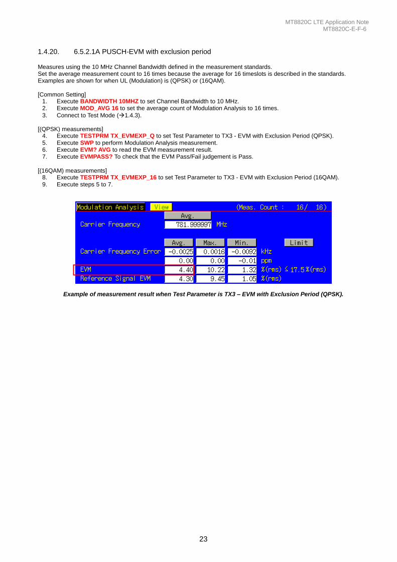
1.4.20. 6.5.2.1A PUSCH-EVM with exclusion period Measures using the 10 MHz Channel Bandwidth defined in the measurement standards. Set the average measurement count to 16 times because the average for 16 timeslots is described in the standards. Examples are shown for when UL (Modulation) is (QPSK) or (16QAM). [Common Setting]
1. Execute BANDWIDTH 10MHZ to set Channel Bandwidth to 10 MHz. 2. Execute MOD_AVG 16 to set the average count of Modulation Analysis to 16 times.
3. Connect to Test Mode (1.4.3). [(QPSK) measurements]
4. Execute TESTPRM TX_EVMEXP_Q to set Test Parameter to TX3 - EVM with Exclusion Period (QPSK). 5. Execute SWP to perform Modulation Analysis measurement. 6. Execute EVM? AVG to read the EVM measurement result. 7. Execute EVMPASS? To check that the EVM Pass/Fail judgement is Pass.
[(16QAM) measurements]
8. Execute TESTPRM TX_EVMEXP_16 to set Test Parameter to TX3 - EVM with Exclusion Period (16QAM).
9. Execute steps 5 to 7.
Example of measurement result when Test Parameter is TX3 – EVM with Exclusion Period (QPSK).
MT8820C LTE Application Note MT8820C-E-F-6
24
1.4.21. 6.5.2.2 Carrier Leakage Measures when UL (Modulation, RB) is (QPSK, PartialRB). An example for 20 measurements is displayed. [Common Setting]
1. Execute MOD_AVG 20 to set the average count of Modulation Analysis to 20 times.
2. Connect to Test Mode (1.4.3). [(QPSK, PartialRB) measurements]
3. Execute TESTPRM TX_0DBM to set Test Parameter to TX1 - IBE/LEAK @ 0 dBm. 4. Execute ULRB_POS MIN to set UL RB Position to Min (#0). 5. Execute SWP to perform Modulation Analysis measurement. 6. Execute CARRLEAK? MAX to read the Carrier Leakage measurement result. 7. Execute CARRLEAKPASS? to check that the Carrier Leakage Pass/Fail judgment is Pass. 8. Execute ULRB_POS MAX to set UL RB Position to Max (#max)
9. Execute steps 5 to 7. 10. Execute TESTPRM TX_M30DBM to set Test Parameter to TX1 - IBE/LEAK @ -30 dB.
11. Execute steps 4 to 9. 12. Execute TESTPRM TX_M40DBM_Q_P to set Test Parameter to TX1 - EVM/IBE/LEAK @ -40 dBm
(QPSK/PartialRB). 13. Execute steps 4 to 9. NOTE 1: The UL RB Position of PartialRB allocation is Min (#0) or Max (#max).
1.4.22. 6.5.2.3 In-band Emissions for Non Allocated RB – PUSCH Measures when UL (Modulation, RB) is (QPSK, PartialRB). An example for 20 measurements is displayed. [Common Setting]
1. Execute MOD_AVG 20 to set the average count of Modulation Analysis to 20 times.
2. Connect to Test Mode (1.4.3). [(QPSK, PartialRB) measurements]
3. Execute TESTPRM TX_0DBM to set Test Parameter to TX1 - IBE/LEAK @ 0 dBm. 4. Execute ULRB_POS MIN to set UL RB Position to Min (#0). 5. Execute SWP to perform Modulation Analysis measurements. 6. Execute INBANDE_GEN? MAX to read the In-Band Emissions (General) measurement result. 7. Execute INBANDE_IMG? MAX to read the In-Band Emissions (IQ Image) measurement result. 8. Execute INBANDE_LEAK? MAX to read the In-Band Emissions (Carrier Leakage) measurement result. 9. Execute INBANDEPASS? to check that the In-Band Emissions Pass/Fail judgment is Pass.
10. Execute ULRB_POS MAX to set UL RB Position to Max (#max).
11. Execute steps 5 to 9. 12. Execute TESTPRM TX_M30DBM to set Test Parameter to TX1 - IBE/LEAK @ -30 dBm.
13. Execute steps 4 to 11. 14. Execute TESTPRM TX_M40DBM_Q_P to set Test Parameter to TX1 - EVM/IBE/LEAK @ -40 dBm
(QPSK/PartialRB). 15. Execute steps 4 to 11. NOTE 1: The UL RB Position of PartialRB allocation is Min (#0) or Max (#max).
MT8820C LTE Application Note MT8820C-E-F-6
25
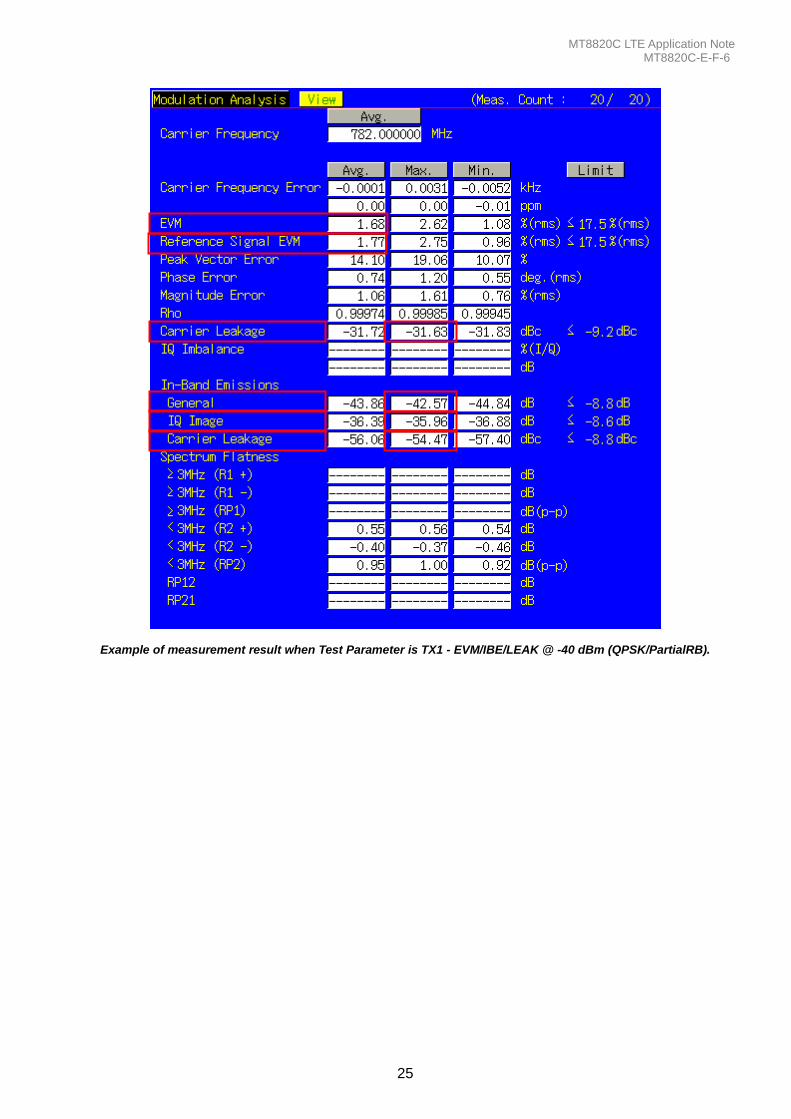
Example of measurement result when Test Parameter is TX1 - EVM/IBE/LEAK @ -40 dBm (QPSK/PartialRB).

MT8820C LTE Application Note MT8820C-E-F-6
26
1.4.23. 6.5.2.3 In-band Emissions for Non Allocated RB – PUCCH An example for 20 measurements is displayed.
1. Execute MOD_AVG 20 to set the average count of Modulation Analysis to 20 times.
2. Connect to Test Mode (1.4.3). 3. Execute TESTPRM TX_PUCCH_0DBM to set Test Parameter to TX2 - PUCCH IBE @ 0 dBm. 4. Execute SWP to perform Modulation Analysis measurement. 5. Execute INBANDE_GEN? MAX to read the In-Band Emissions (General) measurement result. 6. Execute INBANDE_IMG? MAX to read the In-Band Emissions (IQ Image) measurement result. 7. Execute INBANDE_LEAK? MAX to read the In-Band Emissions (Carrier Leakage) measurement result. 8. Execute INBANDEPASS? to check that the In-Band Emissions Pass/Fail judgment is Pass. 9. Execute TESTPRM TX_PUCCH_M30DBM to set Test Parameter to TX2 - PUCCH IBE @ -30 dBm.
10. Execute steps 4 to 8. 11. Execute TESTPRM TX_PUCCH_M40DBM to set Test Parameter to TX2 - PUCCH EVM/IBE @ -40 dBm.
12. Execute steps 4 to 8. NOTE 1: The UL RB Position of PartialRB allocation is Min (#0) or Max (#max).
Example of measurement result when Test Parameter is TX2 - PUCCH IBE @ 0 dBm.
MT8820C LTE Application Note MT8820C-E-F-6
27
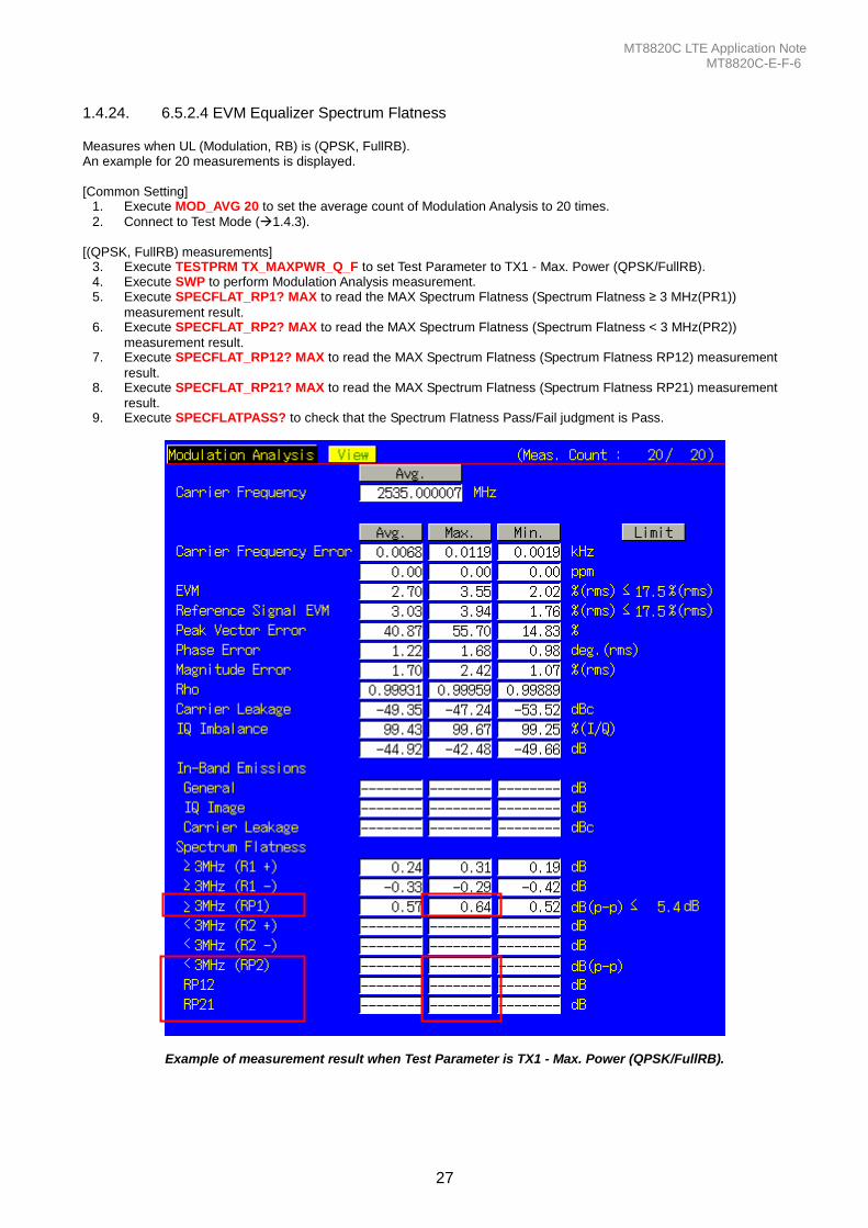
1.4.24. 6.5.2.4 EVM Equalizer Spectrum Flatness Measures when UL (Modulation, RB) is (QPSK, FullRB). An example for 20 measurements is displayed. [Common Setting]
1. Execute MOD_AVG 20 to set the average count of Modulation Analysis to 20 times.
2. Connect to Test Mode (1.4.3). [(QPSK, FullRB) measurements]
3. Execute TESTPRM TX_MAXPWR_Q_F to set Test Parameter to TX1 - Max. Power (QPSK/FullRB). 4. Execute SWP to perform Modulation Analysis measurement. 5. Execute SPECFLAT_RP1? MAX to read the MAX Spectrum Flatness (Spectrum Flatness ≥ 3 MHz(PR1))
measurement result. 6. Execute SPECFLAT_RP2? MAX to read the MAX Spectrum Flatness (Spectrum Flatness < 3 MHz(PR2))
measurement result. 7. Execute SPECFLAT_RP12? MAX to read the MAX Spectrum Flatness (Spectrum Flatness RP12) measurement
result. 8. Execute SPECFLAT_RP21? MAX to read the MAX Spectrum Flatness (Spectrum Flatness RP21) measurement
result. 9. Execute SPECFLATPASS? to check that the Spectrum Flatness Pass/Fail judgment is Pass.
Example of measurement result when Test Parameter is TX1 - Max. Power (QPSK/FullRB).
MT8820C LTE Application Note MT8820C-E-F-6
28
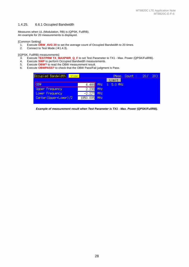
1.4.25. 6.6.1 Occupied Bandwidth Measures when UL (Modulation, RB) is (QPSK, FullRB). An example for 20 measurements is displayed. [Common Setting]
1. Execute OBW_AVG 20 to set the average count of Occupied Bandwidth to 20 times.
2. Connect to Test Mode (1.4.3). [(QPSK, FullRB) measurements]
3. Execute TESTPRM TX_MAXPWR_Q_F to set Test Parameter to TX1 - Max. Power (QPSK/FullRB). 4. Execute SWP to perform Occupied Bandwidth measurements. 5. Execute OBW? to read the OBW measurement result. 6. Execute OBWPASS? to check that the OBW Pass/Fail judgment is Pass.
Example of measurement result when Test Parameter is TX1 - Max. Power (QPSK/FullRB).
MT8820C LTE Application Note MT8820C-E-F-6
29
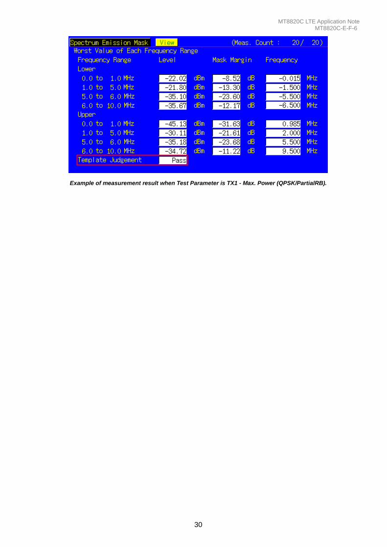
1.4.26. 6.6.2.1 Spectrum Emission Mask Measures when UL (Modulation, RB) is (QPSK, PartialRB), (QPSK, FullRB), (16QAM, PartialRB) or (16QAM, FullRB). An example for 20 measurements is displayed. [Common Setting]
1. Execute SEM_AVG 20 to set the average count of Spectrum Emission Mask to 20 times. 2. Execute TP_SEM5MHZ_1 -13.5 to set the Pass/Fail evaluation value for the Spectrum Emission Mask Frequency
Range 0 – 1 MHz 3. Execute TP_SEM5MHZ_2 -8.5 to set the Pass/Fail evaluation value for the Spectrum Emission Mask Frequency
Range 1 – 5 MHz 4. Execute TP_SEM5MHZ_3 -11.5 to set the Pass/Fail evaluation value for the Spectrum Emission Mask Frequency
Range 5 – 6 MHz 5. Execute TP_SEM5MHZ_4 -23.5 to set the Pass/Fail evaluation value for the Spectrum Emission Mask Frequency
Range 6 – 10 MHz 6. Connect to Test Mode (1.4.3).
[(QPSK, PartialRB) measurements]
7. Execute TESTPRM TX_MAXPWR_Q_P to set Test Parameter to TX1 - Max. Power (QPSK/PartialRB). 8. Execute ULRB_POS MIN to set UL RB Position to Min (#0). 9. Execute SWP to perform Spectrum Emission Mask measurement.
10. Execute SEMPASS? to check that the SEM Pass/Fail judgment is Pass. 11. Execute ULRB_POS MAX to set UL RB Position to Max (#max).
12. Execute steps 9 to 10. [(QPSK, FullRB) measurements] 13. Execute TESTPRM TX_MAXPWR_Q_F to set Test Parameter to TX1 - Max. Power (QPSK/FullRB).
14. Execute steps 9 to 10. [(16QAM, PartialRB) measurements] 15. Execute TESTPRM TX_MAXPWR_16_P to set Test Parameter to TX1 - Max. Power (16QAM/PartialRB)).
16. Execute steps 8 to 12. [(16QAM, FullRB) measurements] 17. Execute TESTPRM TX_MAXPWR_16_F to set Test Parameter to TX1 - Max. Power (16QAM/FullRB).
18. Execute steps 8 to 12. NOTE 1: The PartialRB allocation UL RB Position is divided as follows When Test Frequency is Low range, Max (#max) When Test Frequency is Mid range, Min (#0) and Max (#max) When Test Frequency is High range, Min (#0)
NOTE 2: The Pass/Fail evaluation value is initialized as described in TS36.521-1 6.6.2.1.5, 6.6.2.2.5 and used when the Carrier Frequency is 3 GHz or less. When the Carrier Frequency exceeds 3 GHz, set:
TP_SEM**MHZ_1
TP_SEM**MHZ_2
TP_SEM**MHZ_3
TP_SEM**MHZ_4 as described in TS36.521-1 6.6.2.1.5, 6.6.2.2.5. (** = 1.4, 3, 5, 10, 15, 20).
For the Pass/Fail evaluation values, refer to section 3.7.4 Test Parameter Limit in the operation manual.
MT8820C LTE Application Note MT8820C-E-F-6
30
Example of measurement result when Test Parameter is TX1 - Max. Power (QPSK/PartialRB).
MT8820C LTE Application Note MT8820C-E-F-6
31
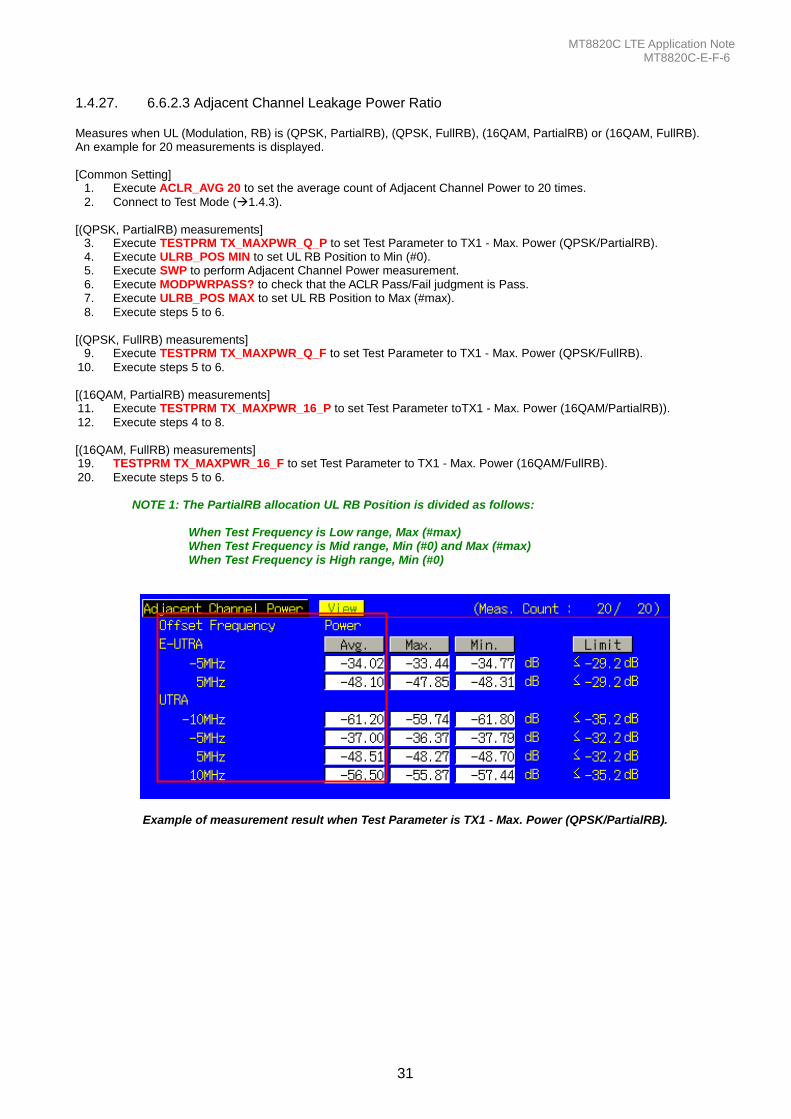
1.4.27. 6.6.2.3 Adjacent Channel Leakage Power Ratio Measures when UL (Modulation, RB) is (QPSK, PartialRB), (QPSK, FullRB), (16QAM, PartialRB) or (16QAM, FullRB). An example for 20 measurements is displayed. [Common Setting]
1. Execute ACLR_AVG 20 to set the average count of Adjacent Channel Power to 20 times.
2. Connect to Test Mode (1.4.3). [(QPSK, PartialRB) measurements]
3. Execute TESTPRM TX_MAXPWR_Q_P to set Test Parameter to TX1 - Max. Power (QPSK/PartialRB). 4. Execute ULRB_POS MIN to set UL RB Position to Min (#0). 5. Execute SWP to perform Adjacent Channel Power measurement. 6. Execute MODPWRPASS? to check that the ACLR Pass/Fail judgment is Pass. 7. Execute ULRB_POS MAX to set UL RB Position to Max (#max).
8. Execute steps 5 to 6. [(QPSK, FullRB) measurements]
9. Execute TESTPRM TX_MAXPWR_Q_F to set Test Parameter to TX1 - Max. Power (QPSK/FullRB).
10. Execute steps 5 to 6. [(16QAM, PartialRB) measurements] 11. Execute TESTPRM TX_MAXPWR_16_P to set Test Parameter toTX1 - Max. Power (16QAM/PartialRB)).
12. Execute steps 4 to 8. [(16QAM, FullRB) measurements] 19. TESTPRM TX_MAXPWR_16_F to set Test Parameter to TX1 - Max. Power (16QAM/FullRB).
20. Execute steps 5 to 6. NOTE 1: The PartialRB allocation UL RB Position is divided as follows: When Test Frequency is Low range, Max (#max) When Test Frequency is Mid range, Min (#0) and Max (#max) When Test Frequency is High range, Min (#0)
Example of measurement result when Test Parameter is TX1 - Max. Power (QPSK/PartialRB).
MT8820C LTE Application Note MT8820C-E-F-6
32
1.4.28. 6.2.4 Additional Maximum Power Reduction (A-MPR)
6.6.2.2 Additional Spectrum Emission Mask Because there are no test parameters supporting Additional Maximum Power Reduction tests and Additional Spectrum Emission Mask tests, select the basic parameter (TX1 – Max. Power (QPSK/FullRB)) and set parameters and standard values required for the test individually. The following shows an example for 20 measurements when the UL Modulation and RB are (QPSK, PartialRB), (QPSK, FullRB), (16QAM, PartialRB) and (16QAM, FullRB) when additionalSpectrumEmission is NS_03, Operating Band is 2, Test Frequency is Mid range, and Test Channel Bandwidth is 5 MHz. [Common Setting]
1. Execute BAND 2 to set Operating Band to 2. 2. Execute PWR_AVG 20 to set the average count of power measurement to 20 times. 3. Execute SEM_AVG 20 to set the average count of Spectrum Emission Mask to 20 times.
4. Connect to Test Mode (1.4.3). 5. Execute TESTPRM TX_MAXPWR_Q_F to set Test parameter to TX1 – Max. Power (QPSK/FullRB). 6. Execute ALLMEASITEMS_OFF to set fundamental measurement items to OFF at one time. 7. Execute PWR_MEAS ON to set Power measurement to ON. 8. Execute SEM_MEAS ON to set Spectrum Emission Mask measurement to ON. 9. Execute SIB2_NS NS_03 to set additionalSpectrumEmission to NS_03.
[For (QPSK, PartialRB) measurement] 10. Execute ULRMC_MOD QPSK to set UL RMC modulation to QPSK. 11. Execute ULRMC_RB 8 to set UL RB number to 8. 12. Execute ULRB_POS MIN to set UL RB Position to Min (#0). 13. Execute TP_MPR1_UL 25.7 to set TX Power measurement Pass/Fail upper limit value to 25.7 dBm. 14. Execute TP_MPR1_LL 19.3 to set TX Power measurement Pass/Fail lower limit value 19.3 dBm. 15. Execute SWP to perform Power measurement. 16. Execute POWER? AVG to read Tx Power measurement result. 17. Execute POWERPASS? to check the measurement result is PASS. 18. Execute SEMPASS? to check SEM result is PASS. 19. Execute ULRB_POS MAX to set UL RB Position to Max (#max).
20. Execute step 15 to 18. 21. Execute ULRMC_RB 6 to set UL RB number to 6. 22. Execute ULRB_POS MIN to set UL RB Position to Min (#0). 23. Execute TP_MPR1_UL 25.7 to set TX Power measurement Pass/Fail upper limit value to 25.7 dBm. 24. Execute TP_MPR1_LL 20.3 to set TX Power measurement Pass/Fail lower limit value 20.3 dBm.
25. Execute step 15 to 18. 26. Execute ULRB_POS MAX to set UL RB Position to Max (#max).
27. Execute steps 15 to 18. [For (QPSK, FullRB) measurement] 28. Execute ULRMC_RB 25 to set UL RB number to 25. 29. Execute TP_MPR1_UL 25.7 to set TX Power measurement Pass/Fail upper limit value to 25.7 dBm. 30. Execute TP_MPR1_LL 18.33 to set TX Power measurement Pass/Fail lower limit value to 18.3 dBm.
31. Execute steps 15 to 18. [For (16QAM, PartialRB) measurement] 32. Execute ULRMC_MOD 16QAM to set UL RMC modulation method to 16QAM. 33. Execute ULRMC_RB 8 to set UL RB number to 8. 34. Execute ULRB_POS MIN to set UL RB Position to Min (#0). 35. Execute TP_MPR1_UL 25.7 to set TX Power measurement Pass/Fail upper limit value to 25.7 dBm. 36. Execute TP_MPR1_LL 18.3 to set TX Power measurement Pass/Fail lower limit value to 18.3 dBm.
37. Execute step 15 to 18. 38. Execute ULRB_POS MAX to set UL RB Position to Max (#max).
39. Execute steps 15 to 18.

MT8820C LTE Application Note MT8820C-E-F-6
33
[For (16QAM, FullRB) measurement] 40. Execute ULRMC_RB 25 to set UL RB number to 25. 41. Execute TP_MPR1_UL 25.7 to set TX Power measurement Pass/Fail upper limit value to 25.7 dBm. 42. Execute TP_MPR1_LL 16.8 to set TX Power measurement Pass/Fail lower limit value to 16.8 dBm.
43. Execute steps 15 to 18. NOTE 1: The UL RB Position for PartialRB allocation is divided as follows: Max (#max) when Test Frequencies is Low range Min (#0) and Max (#max) when Test Frequencies is Mid range Min (#0) when Test Frequencies is High range NOTE 2: There is no need to set separately because the Pass/Fail evaluation value for Spectrum Emission Mask measurement changes in accordance with the additionalSpectrumEmission setting.
MT8820C LTE Application Note MT8820C-E-F-6
34
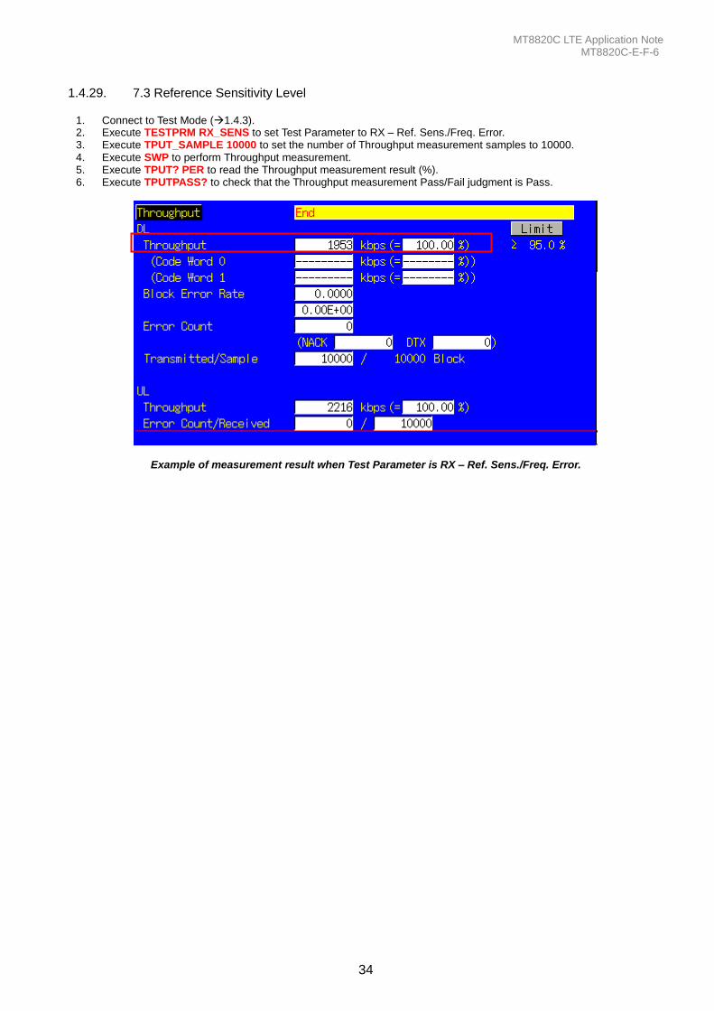
1.4.29. 7.3 Reference Sensitivity Level
1. Connect to Test Mode (1.4.3). 2. Execute TESTPRM RX_SENS to set Test Parameter to RX – Ref. Sens./Freq. Error. 3. Execute TPUT_SAMPLE 10000 to set the number of Throughput measurement samples to 10000. 4. Execute SWP to perform Throughput measurement. 5. Execute TPUT? PER to read the Throughput measurement result (%). 6. Execute TPUTPASS? to check that the Throughput measurement Pass/Fail judgment is Pass.
Example of measurement result when Test Parameter is RX – Ref. Sens./Freq. Error.
MT8820C LTE Application Note MT8820C-E-F-6
35
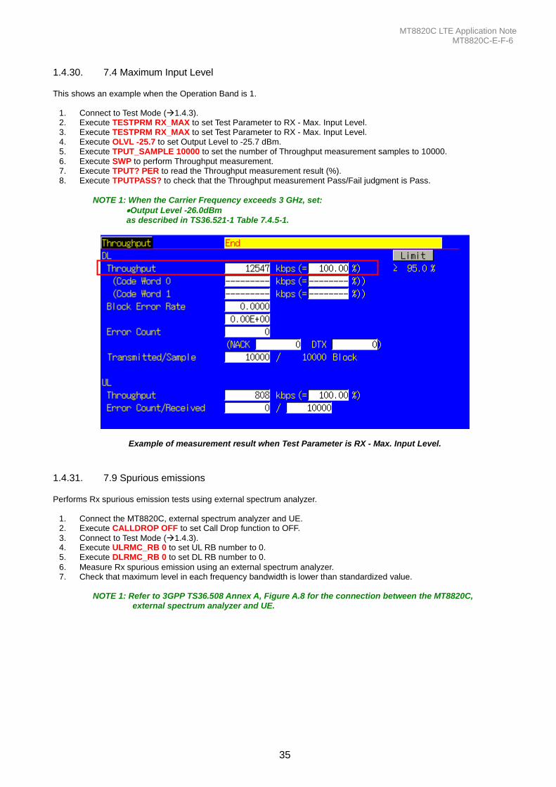
1.4.30. 7.4 Maximum Input Level This shows an example when the Operation Band is 1.
1. Connect to Test Mode (1.4.3). 2. Execute TESTPRM RX_MAX to set Test Parameter to RX - Max. Input Level. 3. Execute TESTPRM RX_MAX to set Test Parameter to RX - Max. Input Level. 4. Execute OLVL -25.7 to set Output Level to -25.7 dBm. 5. Execute TPUT_SAMPLE 10000 to set the number of Throughput measurement samples to 10000. 6. Execute SWP to perform Throughput measurement. 7. Execute TPUT? PER to read the Throughput measurement result (%). 8. Execute TPUTPASS? to check that the Throughput measurement Pass/Fail judgment is Pass.
NOTE 1: When the Carrier Frequency exceeds 3 GHz, set:
Output Level -26.0dBm as described in TS36.521-1 Table 7.4.5-1.
Example of measurement result when Test Parameter is RX - Max. Input Level.
1.4.31. 7.9 Spurious emissions Performs Rx spurious emission tests using external spectrum analyzer.
1. Connect the MT8820C, external spectrum analyzer and UE. 2. Execute CALLDROP OFF to set Call Drop function to OFF.
3. Connect to Test Mode (1.4.3). 4. Execute ULRMC_RB 0 to set UL RB number to 0. 5. Execute DLRMC_RB 0 to set DL RB number to 0.
6. Measure Rx spurious emission using an external spectrum analyzer. 7. Check that maximum level in each frequency bandwidth is lower than standardized value.
NOTE 1: Refer to 3GPP TS36.508 Annex A, Figure A.8 for the connection between the MT8820C, external spectrum analyzer and UE.
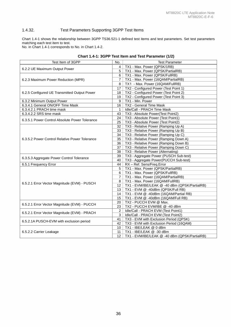
MT8820C LTE Application Note MT8820C-E-F-6
36
1.4.32. Test Parameters Supporting 3GPP Test Items Chart 1.4-1 shows the relationship between 3GPP TS36.521-1 defined test items and test parameters. Set test parameters matching each test item to test. No. in Chart 1.4-1 corresponds to No. in Chart 1.4-2.
Chart 1.4-1: 3GPP Test Item and Test Parameter (1/2)
Test Item of 3GPP No. Test Parameter
6.2.2 UE Maximum Output Power 4 TX1 - Max. Power (QPSK/1RB)
5 TX1 - Max. Power (QPSK/PartialRB)
6.2.3 Maximum Power Reduction (MPR)
6 TX1 - Max. Power (QPSK/FullRB)
7 TX1 - Max. Power (16QAM/PartialRB)
8 TX1 - Max. Power (16QAM/FullRB)
6.2.5 Configured UE Transmitted Output Power
17 TX2 - Configured Power (Test Point 1)
18 TX2 - Configured Power (Test Point 2)
19 TX2 - Configured Power (Test Point 3)
6.3.2 Minimum Output Power 9 TX1 - Min. Power
6.3.4.1 General ON/OFF Time Mask 16 TX2 - General Time Mask
6.3.4.2.1 PRACH time mask 1 Idle/Call - PRACH Time Mask
6.3.4.2.2 SRS time mask 43 TX3 - Absolute Power(Test Point2)
6.3.5.1 Power Control Absolute Power Tolerance 24 TX3 - Absolute Power (Test Point1)
25 TX3 - Absolute Power (Test Point2)
6.3.5.2 Power Control Relative Power Tolerance
32 TX3 - Relative Power (Ramping Up A)
33 TX3 - Relative Power (Ramping Up B)
34 TX3 - Relative Power (Ramping Up C)
35 TX3 - Relative Power (Ramping Down A)
36 TX3 - Relative Power (Ramping Down B)
37 TX3 - Relative Power (Ramping Down C)
38 TX3 - Relative Power (Alternating)
6.3.5.3 Aggregate Power Control Tolerance 39 TX3 - Aggregate Power (PUSCH Sub-test)
40 TX3 - Aggregate Power(PUCCH Sub-test)
6.5.1 Frequency Error 44 RX – Ref. Sens/Freq.Error
6.5.2.1 Error Vector Magnitude (EVM) - PUSCH
5 TX1 - Max. Power (QPSK/PartialRB)
6 TX1 - Max. Power (QPSK/FullRB)
7 TX1 - Max. Power (16QAM/PartialRB)
8 TX1 - Max. Power (16QAM/FullRB)
12 TX1 - EVM/IBE/LEAK @ -40 dBm (QPSK/PartialRB)
13 TX1 - EVM @ -40dBm (QPSK/Full RB)
14 TX1 - EVM @ -40dBm (16QAM/Partial RB)
15 TX1 - EVM @ -40dBm (16QAM/Full RB)
6.5.2.1 Error Vector Magnitude (EVM) - PUCCH 20 TX2 - PUCCH EVM @ Max.
23 TX2 - PUCCH EVM/IBE @ -40 dBm
6.5.2.1 Error Vector Magnitude (EVM) - PRACH 2 Idle/Call - PRACH EVM (Test Point1)
3 Idle/Call - PRACH EVM (Test Point2)
6.5.2.1A PUSCH-EVM with exclusion period 41 TX3 - EVM with Exclusion Period (QPSK)
42 TX3 - EVM with Exclusion Period (16QAM)
6.5.2.2 Carrier Leakage
10 TX1 - IBE/LEAK @ 0 dBm
11 TX1 - IBE/LEAK @ -30 dBm
12 TX1 - EVM/IBE/LEAK @ -40 dBm (QPSK/PartialRB)
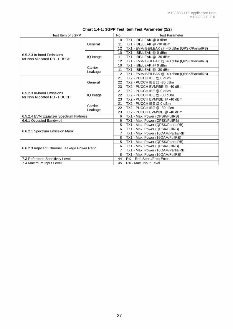
MT8820C LTE Application Note MT8820C-E-F-6
37
Chart 1.4-1: 3GPP Test Item Test Parameter (2/2)
Test Item of 3GPP No. Test Parameter
6.5.2.3 In-band Emissions for Non Allocated RB - PUSCH
General
10 TX1 - IBE/LEAK @ 0 dBm
11 TX1 - IBE/LEAK @ -30 dBm
12 TX1 - EVM/IBE/LEAK @ -40 dBm (QPSK/PartialRB)
IQ Image
10 TX1 - IBE/LEAK @ 0 dBm
11 TX1 - IBE/LEAK @ -30 dBm
12 TX1 - EVM/IBE/LEAK @ -40 dBm (QPSK/PartialRB)
Carrier Leakage
10 TX1 - IBE/LEAK @ 0 dBm
11 TX1 - IBE/LEAK @ -30 dBm
12 TX1 - EVM/IBE/LEAK @ -40 dBm (QPSK/PartialRB)
6.5.2.3 In-band Emissions for Non Allocated RB - PUCCH
General
21 TX2 - PUCCH IBE @ 0 dBm
22 TX2 - PUCCH IBE @ -30 dBm
23 TX2 - PUCCH EVM/IBE @ -40 dBm
IQ Image
21 TX2 - PUCCH IBE @ 0 dBm
22 TX2 - PUCCH IBE @ -30 dBm
23 TX2 - PUCCH EVM/IBE @ -40 dBm
Carrier Leakage
21 TX2 - PUCCH IBE @ 0 dBm
22 TX2 - PUCCH IBE @ -30 dBm
23 TX2 - PUCCH EVM/IBE @ -40 dBm
6.5.2.4 EVM Equalizer Spectrum Flatness 6 TX1 - Max. Power (QPSK/FullRB)
6.6.1 Occupied Bandwidth 6 TX1 - Max. Power (QPSK/FullRB)
6.6.2.1 Spectrum Emission Mask
5 TX1 - Max. Power (QPSK/PartialRB)
6 TX1 - Max. Power (QPSK/FullRB)
7 TX1 - Max. Power (16QAM/PartialRB)
8 TX1 - Max. Power (16QAM/FullRB)
6.6.2.3 Adjacent Channel Leakage Power Ratio
5 TX1 - Max. Power (QPSK/PartialRB)
6 TX1 - Max. Power (QPSK/FullRB)
7 TX1 - Max. Power (16QAM/PartialRB)
8 TX1 - Max. Power (16QAM/FullRB)
7.3 Reference Sensitivity Level 44 RX – Ref. Sens./Freq.Error
7.4 Maximum Input Level 45 RX - Max. Input Level
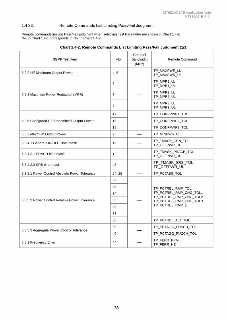
MT8820C LTE Application Note MT8820C-E-F-6
38
1.4.33. Remote Commands List Limiting Pass/Fail Judgment Remote commands limiting Pass/Fail judgment when selecting Test Parameter are shown in Chart 1.4-2. No. in Chart 1.4-1 corresponds to No. in Chart 1.4-2.
Chart 1.4-2: Remote Commands List Limiting Pass/Fail Judgment (1/3)
3GPP Test Item No.
Channel
Bandwidth
(MHz)
Remote Command
6.2.2 UE Maximum Output Power 4, 5 ----- TP_MAXPWR_LL
TP_MAXPWR_UL
6.2.3 Maximum Power Reduction (MPR)
6
-----
TP_MPR1_LL
TP_MPR1_UL
7 TP_MPR2_LL
TP_MPR2_UL
8 TP_MPR3_LL
TP_MPR3_UL
6.2.5 Configured UE Transmitted Output Power
17
-----
TP_CONFPWR1_TOL
18 TP_CONFPWR2_TOL
19 TP_CONFPWR3_TOL
6.3.2 Minimum Output Power 9 ----- TP_MINPWR_UL
6.3.4.1 General ON/OFF Time Mask 16 ----- TP_TMASK_GEN_TOL
TP_OFFPWR_UL
6.3.4.2.1 PRACH time mask 1 ----- TP_TMASK_PRACH_TOL
TP_OFFPWR_UL
6.3.4.2.2 SRS time mask 43 ----- TP_TMASK_SRS_TOL TP_OFFPWR_UL
6.3.5.1 Power Control Absolute Power Tolerance 24, 25 ----- TP_PCTABS_TOL
6.3.5.2 Power Control Relative Power Tolerance
32
-----
TP_PCTREL_RMP_TOL
TP_PCTREL_RMP_CNG_TOL1
TP_PCTREL_RMP_CNG_TOL2
TP_PCTREL_RMP_CNG_TOL3
TP_PCTREL_RMP_E
33
34
35
36
37
38 TP_PCTREL_ALT_TOL
6.3.5.3 Aggregate Power Control Tolerance 39
----- TP_PCTAGG_PUSCH_TOL
40 TP_PCTAGG_PUCCH_TOL
6.5.1 Frequency Error 44 ----- TP_FERR_PPM
TP_FERR_HZ
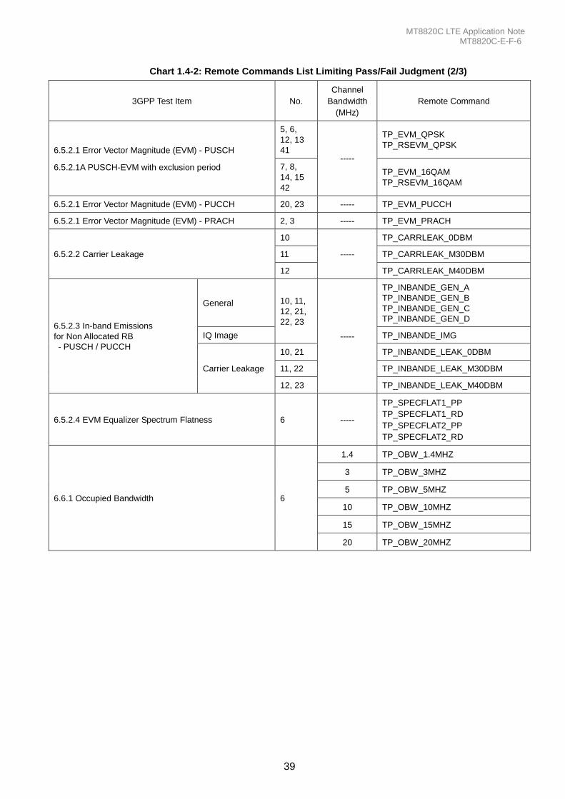
MT8820C LTE Application Note MT8820C-E-F-6
39
Chart 1.4-2: Remote Commands List Limiting Pass/Fail Judgment (2/3)
3GPP Test Item No.
Channel
Bandwidth
(MHz)
Remote Command
6.5.2.1 Error Vector Magnitude (EVM) - PUSCH
6.5.2.1A PUSCH-EVM with exclusion period
5, 6,
12, 13
41 -----
TP_EVM_QPSK
TP_RSEVM_QPSK
7, 8,
14, 15
42
TP_EVM_16QAM
TP_RSEVM_16QAM
6.5.2.1 Error Vector Magnitude (EVM) - PUCCH 20, 23 ----- TP_EVM_PUCCH
6.5.2.1 Error Vector Magnitude (EVM) - PRACH 2, 3 ----- TP_EVM_PRACH
6.5.2.2 Carrier Leakage
10
-----
TP_CARRLEAK_0DBM
11 TP_CARRLEAK_M30DBM
12 TP_CARRLEAK_M40DBM
6.5.2.3 In-band Emissions
for Non Allocated RB
- PUSCH / PUCCH
General 10, 11,
12, 21,
22, 23
-----
TP_INBANDE_GEN_A
TP_INBANDE_GEN_B
TP_INBANDE_GEN_C
TP_INBANDE_GEN_D
IQ Image TP_INBANDE_IMG
Carrier Leakage
10, 21 TP_INBANDE_LEAK_0DBM
11, 22 TP_INBANDE_LEAK_M30DBM
12, 23 TP_INBANDE_LEAK_M40DBM
6.5.2.4 EVM Equalizer Spectrum Flatness 6 -----
TP_SPECFLAT1_PP
TP_SPECFLAT1_RD
TP_SPECFLAT2_PP
TP_SPECFLAT2_RD
6.6.1 Occupied Bandwidth 6
1.4 TP_OBW_1.4MHZ
3 TP_OBW_3MHZ
5 TP_OBW_5MHZ
10 TP_OBW_10MHZ
15 TP_OBW_15MHZ
20 TP_OBW_20MHZ
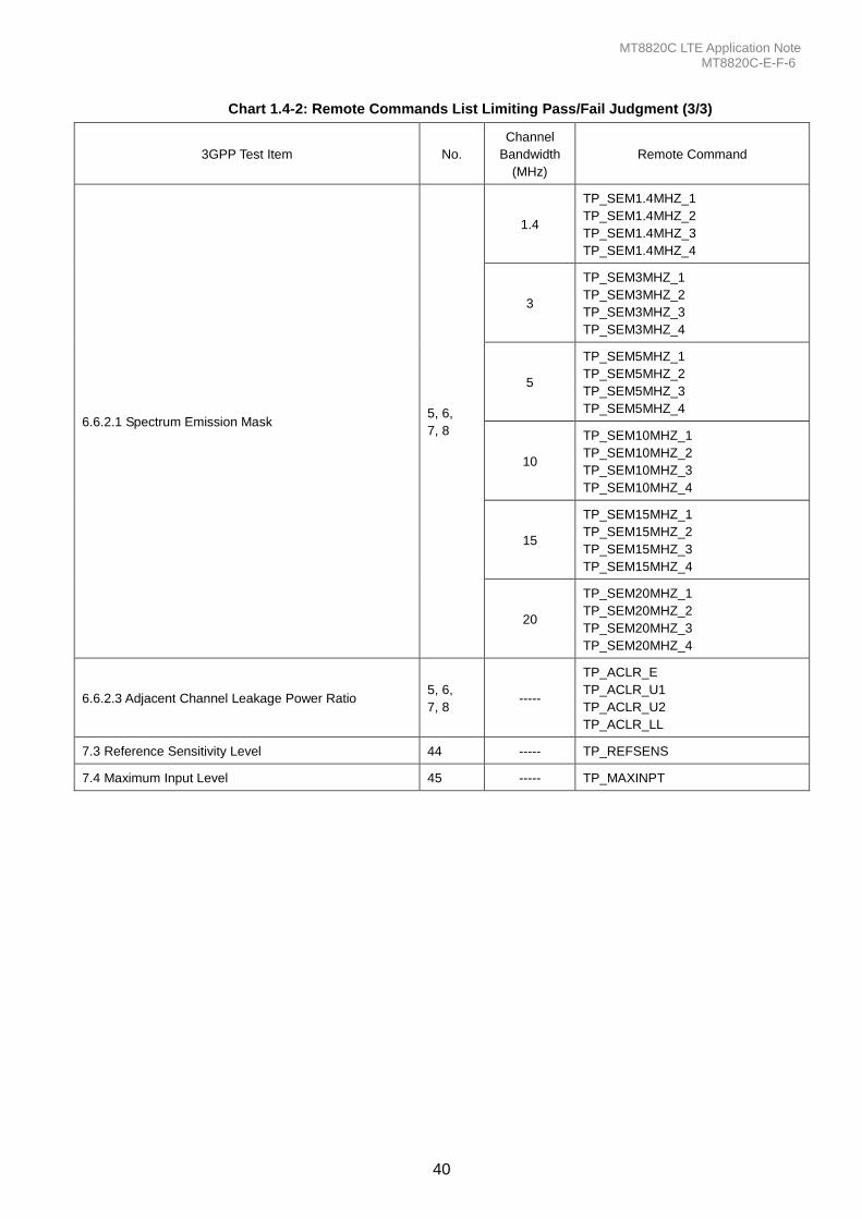
MT8820C LTE Application Note MT8820C-E-F-6
40
Chart 1.4-2: Remote Commands List Limiting Pass/Fail Judgment (3/3)
3GPP Test Item No.
Channel
Bandwidth
(MHz)
Remote Command
6.6.2.1 Spectrum Emission Mask 5, 6,
7, 8
1.4
TP_SEM1.4MHZ_1
TP_SEM1.4MHZ_2
TP_SEM1.4MHZ_3
TP_SEM1.4MHZ_4
3
TP_SEM3MHZ_1
TP_SEM3MHZ_2
TP_SEM3MHZ_3
TP_SEM3MHZ_4
5
TP_SEM5MHZ_1
TP_SEM5MHZ_2
TP_SEM5MHZ_3
TP_SEM5MHZ_4
10
TP_SEM10MHZ_1
TP_SEM10MHZ_2
TP_SEM10MHZ_3
TP_SEM10MHZ_4
15
TP_SEM15MHZ_1
TP_SEM15MHZ_2
TP_SEM15MHZ_3
TP_SEM15MHZ_4
20
TP_SEM20MHZ_1
TP_SEM20MHZ_2
TP_SEM20MHZ_3
TP_SEM20MHZ_4
6.6.2.3 Adjacent Channel Leakage Power Ratio 5, 6,
7, 8 -----
TP_ACLR_E
TP_ACLR_U1
TP_ACLR_U2
TP_ACLR_LL
7.3 Reference Sensitivity Level 44 ----- TP_REFSENS
7.4 Maximum Input Level 45 ----- TP_MAXINPT
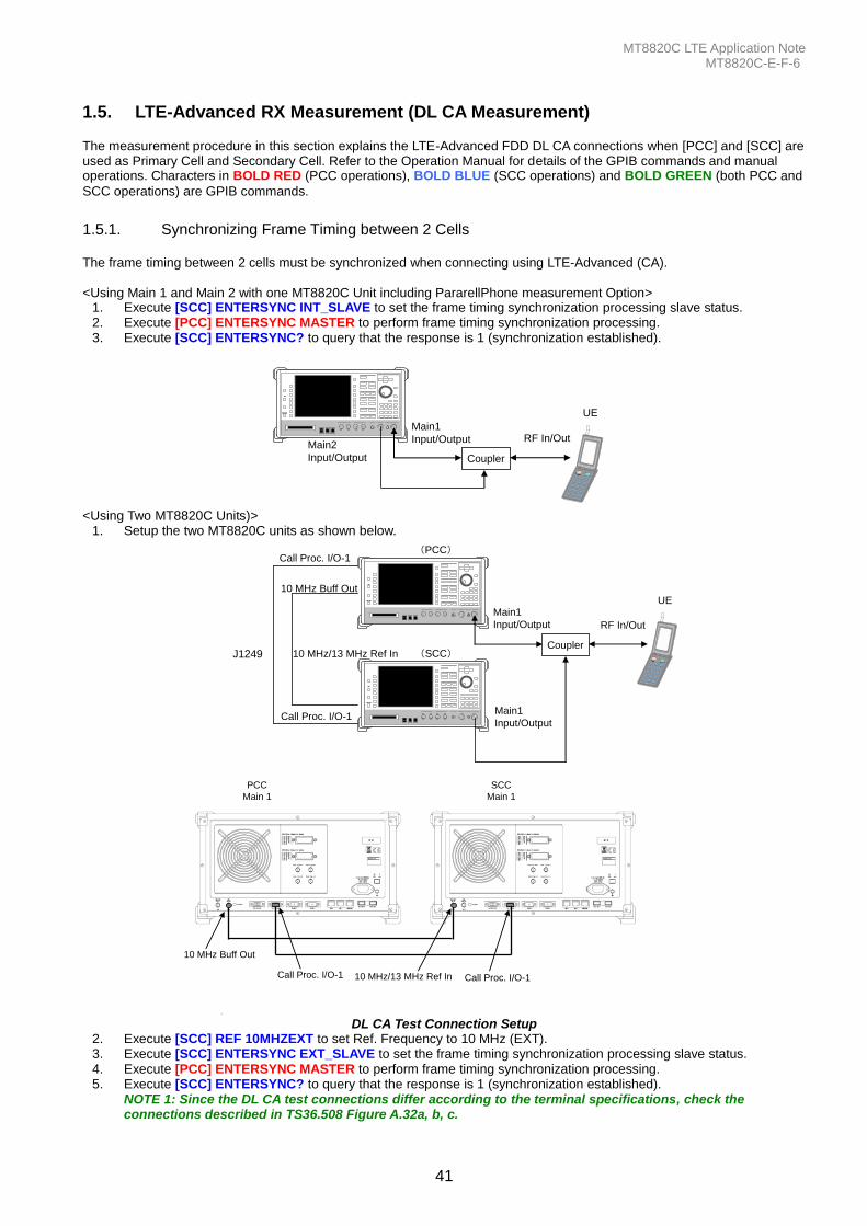
MT8820C LTE Application Note MT8820C-E-F-6
41
1.5. LTE-Advanced RX Measurement (DL CA Measurement) The measurement procedure in this section explains the LTE-Advanced FDD DL CA connections when [PCC] and [SCC] are used as Primary Cell and Secondary Cell. Refer to the Operation Manual for details of the GPIB commands and manual operations. Characters in BOLD RED (PCC operations), BOLD BLUE (SCC operations) and BOLD GREEN (both PCC and
SCC operations) are GPIB commands.
1.5.1. Synchronizing Frame Timing between 2 Cells The frame timing between 2 cells must be synchronized when connecting using LTE-Advanced (CA). <Using Main 1 and Main 2 with one MT8820C Unit including PararellPhone measurement Option>
1. Execute [SCC] ENTERSYNC INT_SLAVE to set the frame timing synchronization processing slave status. 2. Execute [PCC] ENTERSYNC MASTER to perform frame timing synchronization processing. 3. Execute [SCC] ENTERSYNC? to query that the response is 1 (synchronization established).
Main2
Input/Output
RF In/Out
UE
Coupler
Main1
Input/Output
<Using Two MT8820C Units)>
1. Setup the two MT8820C units as shown below.
Main1
Input/Output
Main1
Input/Output
RF In/Out
UE
10 MHz/13 MHz Ref In
Call Proc. I/O-1
Call Proc. I/O-1
10 MHz Buff Out
J1249 Coupler
(SCC)
(PCC)
Call Proc. I/O-1 Call Proc. I/O-1
10 MHz Buff Out
10 MHz/13 MHz Ref In
PCC
Main 1
SCC
Main 1
DL CA Test Connection Setup
2. Execute [SCC] REF 10MHZEXT to set Ref. Frequency to 10 MHz (EXT). 3. Execute [SCC] ENTERSYNC EXT_SLAVE to set the frame timing synchronization processing slave status. 4. Execute [PCC] ENTERSYNC MASTER to perform frame timing synchronization processing. 5. Execute [SCC] ENTERSYNC? to query that the response is 1 (synchronization established).
NOTE 1: Since the DL CA test connections differ according to the terminal specifications, check the connections described in TS36.508 Figure A.32a, b, c.
MT8820C LTE Application Note MT8820C-E-F-6
42
1.5.2. Setting Initial Conditions The initial conditions before measurement must be set.
1.5.2.1. Setting Example 1 This shows an example when setting Operating Band to 1, Test Frequency to Mid range, and Test Channel Bandwidth PCC and SCC both to 10 MHz.
1. Execute [PCC/SCC] PRESET to set the default parameters. 2. Execute [PCC] CHCODING RMC_DL_CA_PCC to set Channel Coding to RMC (DL CA - PCC). 3. Execute [SCC] CHCODING RMC_DL_CA_SCC to set Channel Coding RMC (DL CA - SCC). 4. Execute [PCC] CALLPROC ON to set Call Processing to On. 5. Execute [SCC] CALLPROC OFF to set Call Processing to Off. 6. Execute [PCC] DLCHAN 200 to set UL Channel and DL Channel to 18200 (1940MHz) and 200 (2130MHz),
respectively. 7. Execute [SCC] ULCHAN PCC 18200 to set Call Processing - DL Carrier aggregation PCC - UL Channel to 18200. 8. Execute [PCC] DLCHAN SCC1 400 to set Call Processing - DL Carrier aggregation SCC-1 - DL Channel to 400. 9. Execute [SCC] DLCHAN 400 to set DL Channel to 400(2150MHz), respectively.
10. Execute [PCC] BANDWIDTH 10MHZ to set Channel Bandwidth to 10 MHz. 11. Execute [SCC] BANDWIDTH PCC 10MHZ to set Call Processing - DL Carrier aggregation PCC - Channel Bandwidth
to 10 MHz. 12. Execute [PCC] BANDWIDTH SCC1 10MHZ to set Call Processing - DL Carrier aggregation SCC-1 - Channel
Bandwidth to 10 MHz. 13. Execute [SCC] BANDWIDTH 10MHZ to set Channel Bandwidth to 10 MHz.
1.5.2.2. Setting Example 2 This shows an example when setting Operating Band to 1, Test Frequency to Mid range, and Test Channel Bandwidth PCC and SCC both to 15 MHz.
1. Execute [PCC/SCC] PRESET to set the default parameters. 2. Execute [PCC] CHCODING RMC_DL_CA_PCC to set Channel Coding to RMC (DL CA - PCC). 3. Execute [SCC] CHCODING RMC_DL_CA_SCC to set Channel Coding RMC (DL CA - SCC). 4. Execute [PCC] CALLPROC ON to set Call Processing to On. 5. Execute [SCC] CALLPROC OFF to set Call Processing to Off. 6. Execute [PCC] DLCHAN 200 to set UL Channel and DL Channel to 18200 (1940MHz) and 200 (2130MHz),
respectively. 7. Execute [SCC] ULCHAN PCC 18200 to set Call Processing - DL Carrier aggregation PCC - UL Channel to 18200. 8. Execute [PCC] DLCHAN SCC1 350 to set Call Processing - DL Carrier aggregation SCC-1 - DL Channel to 350. 9. Execute [SCC] DLCHAN 350 to set DL Channel to 350(2145MHz), respectively.
10. Execute [PCC] BANDWIDTH 15MHZ to set Channel Bandwidth to 15 MHz. 11. Execute [SCC] BANDWIDTH PCC 15MHZ to set Call Processing - DL Carrier aggregation PCC - Channel Bandwidth
to 15 MHz. 12. Execute [PCC] BANDWIDTH SCC1 15MHZ to set Call Processing - DL Carrier aggregation SCC-1 - Channel
Bandwidth to 15 MHz. 13. Execute [SCC] BANDWIDTH 15MHZ to set Channel Bandwidth to 15 MHz.
1.5.2.3. Setting Example 3 This shows an example when setting Operating Band to PCC:1 and SCC:5, and Test Channel Bandwidth PCC and SCC both to 10MHz.
1. Execute [PCC/SCC] PRESET to set the default parameters. 2. Execute [PCC] CHCODING RMC_DL_CA_PCC to set Channel Coding to RMC (DL CA - PCC). 3. Execute [SCC] CHCODING RMC_DL_CA_SCC to set Channel Coding RMC (DL CA - SCC). 4. Execute [PCC] CALLPROC ON to set Call Processing to On. 5. Execute [SCC] CALLPROC OFF to set Call Processing to Off. 6. Execute [PCC] DLCHAN 200 to set UL Channel and DL Channel to 18200 (1940MHz) and 200 (2130MHz),
respectively. 7. Execute [SCC] ULCHAN PCC 18200 to set Call Processing - DL Carrier aggregation PCC - UL Channel to 18200. 8. Execute [PCC] DLCHAN SCC1 2525 to set Call Processing - DL Carrier aggregation SCC-1 - DL Channel to 2525. 9. Execute [SCC] DLCHAN 2525 to set DL Channel to 2525(881.5MHz), respectively.
10. Execute [PCC] BANDWIDTH 10MHZ to set Channel Bandwidth to 10 MHz. 11. Execute [SCC] BANDWIDTH PCC 10MHZ to set Call Processing - DL Carrier aggregation PCC - Channel Bandwidth
to 10 MHz. 12. Execute [PCC] BANDWIDTH SCC1 10MHZ to set Call Processing - DL Carrier aggregation SCC-1 - Channel
Bandwidth to 10 MHz. 13. Execute [SCC] BANDWIDTH 10MHZ to set Channel Bandwidth to 10 MHz.
MT8820C LTE Application Note MT8820C-E-F-6
43
1.5.3. Location Registration This performs UE Location Registration after setting the initial conditions (1.5.2.1.).
1. Connect the UE and MT8820C. 2. Execute [SCC] LVL OFF to set SCell output to off. 3. Execute [PCC] CALLRFR to clear the UE Report and call processing status. 4. Execute [PCC] CALLSTAT? to query the call processing status.
5. Check that the results of step 4 are 1 (= idle). 6. Set the UE to On. 7. Execute [PCC] CALLSTAT? to query the call processing status.
8. Check that the result of step 7 is 2 (= Idle(Regist)). (If the result of step 7 is not 2 (= Idle(Regist)), repeat step 7.)
9. Execute [SCC] LVL ON to set SCell output to off.
1.5.4. Test Mode Connection This makes the Test Mode connection after UE Location Registration. Location Registration must be completed before call connection. (1.5.3)
1. Execute [PCC] CALLSA to connect a Start Call in the Test Mode. 2. Execute [PCC] CALLSTATIC? to query the call processing nominal status.
3. Check that the result of the query in step 2 is 6 ( = Connected).
1.5.5. Channel Change at Handover This shows a setting example when the Operating Band is 1, and Test Frequency is set to High range. <Changing PCC channel>
1. Execute [PCC] DLCHAN 302 to set UL Channel and DL Channel to 18302 and 302, respectively. 2. Execute [SCC] ULCHAN_PCC 18302 to set Call Processing - DL Carrier aggregation PCC - UL Channel to 18302.
<Changing SCC channel>
3. Execute [PCC] DLCHAN_SCC1 500 to set Call Processing - DL Carrier aggregation SCC-1 - DL Channel to 500. 4. Execute [SCC] DLCHAN 500 to set DL Channel to 500.
*Steps 1 and 3 can be executed simultaneously by executing [PCC] DLCHAN 302,500.
1.5.6. Bandwidth Change at Handover This shows a setting example when the Channel Bandwidth PCC and SCC are set to 20 MHz and 15 MHz, respectively. <Changing PCC Bandwidth>
1. Execute [PCC] BANDWIDTH 20MHZ to set Channel Bandwidth to 20 MHz. 2. Execute [SCC] BANDWIDTH_PCC 20MHZ to set Call Processing - DL Carrier aggregation PCC - Channel
Bandwidth to 20 MHz. <Changing SCC Bandwidth>
3. Execute [PCC] BANDWIDTH_SCC1 15MHZ to set Call Processing - DL Carrier aggregation SCC-1 - Channel
Bandwidth to 15 MHz. 4. Execute [SCC] BANDWIDTH 15MHZ to set Channel Bandwidth to 15 MHz.
1.5.7. Changing PCell DL RB Allocation This shows a setting example when Channel Bandwidth is 10 MHz. This performs UE call connection after setting the initial conditions (1.5.4.).
1. Execute [PCC] DLRMC_RB 25 to set DL RMC - Number of RB to 25. 2. Execute [PCC] DLIMCS1 5 to set DL RMC - MCS Index 1 to 5. 3. Execute [PCC] DLIMCS2 6 to set DL RMC - MCS Index 2 to 6. 4. Execute [PCC] DLIMCS3 7 to set DL RMC - MCS Index 3 to 7.
MT8820C LTE Application Note MT8820C-E-F-6
44
1.5.8. Changing SCell DL RB Allocation This shows a setting example when Channel Bandwidth is 10 MHz. This performs UE call connection after setting the initial conditions (1.5.4.).
1. Execute [SCC] DLRMC_RB 25 to set DL RMC - Number of RB to 25. 2. Execute [PCC] DLRMC_RB_SCC1 25 to set Call Processing - DL Carrier aggregation SCC-1 - DL RMC - Number of
RB to 25. 3. Execute [SCC] DLIMCS1 5 to set DL RMC - MCS Index 1 to 5. 4. Execute [PCC] DLIMCS1_SCC1 5 to set Call Processing - DL Carrier aggregation SCC-1 - DL RMC - MCS Index 1
to 5. 5. Execute [SCC] DLIMCS2 6 to set DL RMC - MCS Index 2 to 6. 6. Execute [PCC] DLIMCS2_SCC1 6 to set Call Processing - DL Carrier aggregation SCC-1 - DL RMC - MCS Index 2
to 6. 7. Execute [SCC] DLIMCS3 7 to set DL RMC - MCS Index 3 to 7. 8. Execute [PCC] DLIMCS3_SCC1 7 to set Call Processing - DL Carrier aggregation SCC-1 - DL RMC - MCS Index 3
to 7.
1.5.9. PCell UL RB Allocation Change This shows a setting example when Channel Bandwidth is 10 MHz This performs UE call connection after setting the initial conditions (1.5.4.).
1. Execute [PCC] ULRMC_RB 20 to set UL RMC - Number of RB to 20. 2. Execute [SCC] ULRMC_RB_PCC 20 to set Call Processing - DL Carrier aggregation PCC - UL RMC - Number of RB
to 20. 3. Execute [PCC] ULRB_START 5 to set UL RMC - Starting RB to 5. 4. Execute [SCC] ULRB_START_PCC 5 to set Call Processing - DL Carrier aggregation PCC - UL RMC - Starting RB
to 5. 5. Execute [PCC] ULIMCS 6 to set UL RMC - MCS Index to 6. 6. Execute [SCC] ULIMCS_PCC 6 to set Call Processing - DL Carrier aggregation PCC - UL RMC - MCS Index to 6. 7. Execute [PCC] ULRMC_MOD QPSK to set UL RMC - Modulation to QPSK. 8. Execute [SCC] ULRMC_MOD_PCC QPSK to set Call Processing - DL Carrier aggregation PCC - UL RMC -
Modulation to QPSK.
1.5.10. Stopping Test Mode
1. Execute [PCC] CALLSO to stop an End Call the Test Mode. 2. Execute [PCC] CALLSTATIC? to query the call processing nominal status.
3. Check the the result of the query in step 2 is 2 ( = Idle(Regist)).
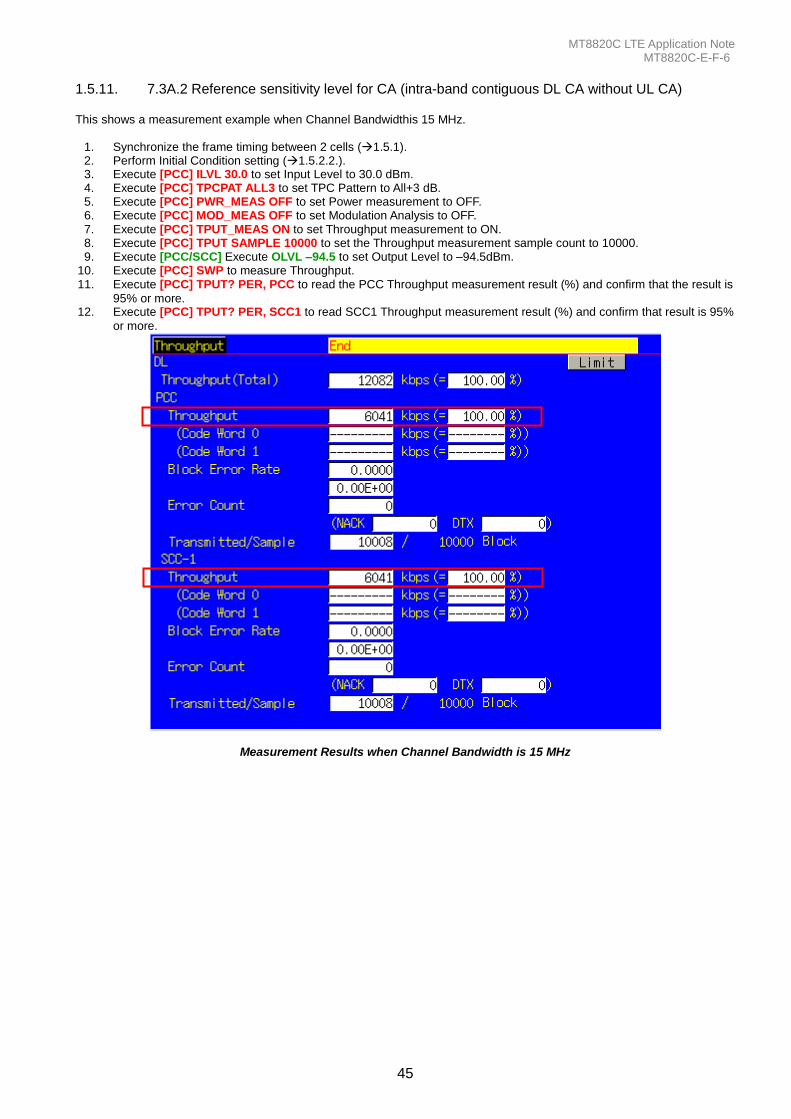
MT8820C LTE Application Note MT8820C-E-F-6
45
1.5.11. 7.3A.2 Reference sensitivity level for CA (intra-band contiguous DL CA without UL CA) This shows a measurement example when Channel Bandwidthis 15 MHz.
1. Synchronize the frame timing between 2 cells (1.5.1). 2. Perform Initial Condition setting (1.5.2.2.). 3. Execute [PCC] ILVL 30.0 to set Input Level to 30.0 dBm. 4. Execute [PCC] TPCPAT ALL3 to set TPC Pattern to All+3 dB. 5. Execute [PCC] PWR_MEAS OFF to set Power measurement to OFF. 6. Execute [PCC] MOD_MEAS OFF to set Modulation Analysis to OFF. 7. Execute [PCC] TPUT_MEAS ON to set Throughput measurement to ON. 8. Execute [PCC] TPUT SAMPLE 10000 to set the Throughput measurement sample count to 10000. 9. Execute [PCC/SCC] Execute OLVL –94.5 to set Output Level to –94.5dBm.
10. Execute [PCC] SWP to measure Throughput. 11. Execute [PCC] TPUT? PER, PCC to read the PCC Throughput measurement result (%) and confirm that the result is
95% or more. 12. Execute [PCC] TPUT? PER, SCC1 to read SCC1 Throughput measurement result (%) and confirm that result is 95%
or more.
Measurement Results when Channel Bandwidth is 15 MHz
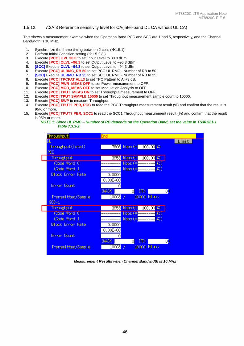
MT8820C LTE Application Note MT8820C-E-F-6
46
1.5.12. 7.3A.3 Reference sensitivity level for CA(inter-band DL CA without UL CA) This shows a measurement example when the Operation Band PCC and SCC are 1 and 5, respectively, and the Channel Bandwidth is 10 MHz.
1. Synchronize the frame timing between 2 cells (1.5.1). 2. Perform Initial Condition setting (1.5.2.3.). 3. Execute [PCC] ILVL 30.0 to set Input Level to 30.0 dBm. 4. Execute [PCC] OLVL –96.3 to set Output Level to –96.3 dBm. 5. [SCC] Execute OLVL –94.3 to set Output Level to –94.3 dBm. 6. Execute [PCC] ULRMC_RB 50 to set PCC UL RMC - Number of RB to 50. 7. [SCC] Execute ULRMC_RB 25 to set SCC UL RMC - Number of RB to 25. 8. Execute [PCC] TPCPAT ALL3 to set TPC Pattern to All+3 dB. 9. Execute [PCC] PWR_MEAS OFF to set Power measurement to OFF.
10. Execute [PCC] MOD_MEAS OFF to set Modulation Analysis to OFF. 11. Execute [PCC] TPUT_MEAS ON to set Throughput measurement to OFF. 12. Execute [PCC] TPUT SAMPLE 10000 to set Throughput measurement sample count to 10000. 13. Execute [PCC] SWP to measure Throughput. 14. Execute [PCC] TPUT? PER, PCC to read the PCC Throughput measurement result (%) and confirm that the result is
95% or more. 15. Execute [PCC] TPUT? PER, SCC1 to read the SCC1 Throughput measurement result (%) and confirm that the result
is 95% or more. NOTE 1: Since UL RMC – Number of RB depends on the Operation Band, set the value in TS36.521-1
Table 7.3.3-2.
Measurement Results when Channel Bandwidth is 10 MHz
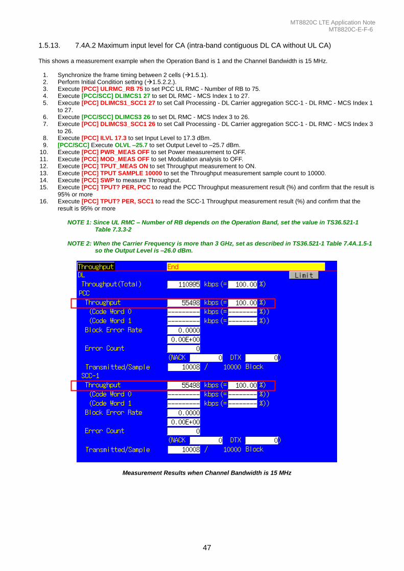
MT8820C LTE Application Note MT8820C-E-F-6
47
1.5.13. 7.4A.2 Maximum input level for CA (intra-band contiguous DL CA without UL CA) This shows a measurement example when the Operation Band is 1 and the Channel Bandwidth is 15 MHz.
1. Synchronize the frame timing between 2 cells (1.5.1). 2. Perform Initial Condition setting (1.5.2.2.). 3. Execute [PCC] ULRMC_RB 75 to set PCC UL RMC - Number of RB to 75. 4. Execute [PCC/SCC] DLIMCS1 27 to set DL RMC - MCS Index 1 to 27. 5. Execute [PCC] DLIMCS1_SCC1 27 to set Call Processing - DL Carrier aggregation SCC-1 - DL RMC - MCS Index 1
to 27. 6. Execute [PCC/SCC] DLIMCS3 26 to set DL RMC - MCS Index 3 to 26. 7. Execute [PCC] DLIMCS3_SCC1 26 to set Call Processing - DL Carrier aggregation SCC-1 - DL RMC - MCS Index 3
to 26. 8. Execute [PCC] ILVL 17.3 to set Input Level to 17.3 dBm. 9. [PCC/SCC] Execute OLVL –25.7 to set Output Level to –25.7 dBm.
10. Execute [PCC] PWR_MEAS OFF to set Power measurement to OFF. 11. Execute [PCC] MOD_MEAS OFF to set Modulation analysis to OFF. 12. Execute [PCC] TPUT_MEAS ON to set Throughput measurement to ON. 13. Execute [PCC] TPUT SAMPLE 10000 to set the Throughput measurement sample count to 10000. 14. Execute [PCC] SWP to measure Throughput. 15. Execute [PCC] TPUT? PER, PCC to read the PCC Throughput measurement result (%) and confirm that the result is
95% or more 16. Execute [PCC] TPUT? PER, SCC1 to read the SCC-1 Throughput measurement result (%) and confirm that the
result is 95% or more
NOTE 1: Since UL RMC – Number of RB depends on the Operation Band, set the value in TS36.521-1 Table 7.3.3-2
NOTE 2: When the Carrier Frequency is more than 3 GHz, set as described in TS36.521-1 Table 7.4A.1.5-1
so the Output Level is –26.0 dBm.
Measurement Results when Channel Bandwidth is 15 MHz
MT8820C LTE Application Note MT8820C-E-F-6
48
1.6. UE Report
1.6.1. Measurement Report Report UE information every 480 ms.
1. Connect to Test Mode (1.4.3). 2. Execute MEASREP ON to report UE information. 3. Execute CALLRFR to initialize UE Report value. 4. Execute RSRP? FLAG. When the response is 1, RSRP is returned from the UE. 5. Execute RSRP? to read the RSRP value.
6. Return to step 3 to read the Report value again.
1.6.2. Measurement Report Report UE information once.
1. Connect to Test Mode (1.4.3).
2. Execute MEASREP OFF to report UE information.
3. Execute MEASREP_ONCE to report UE information once.
4. Execute CALLRFR to initialize UE Report value.
5. Execute RSRP? FLAG. When the response is 1, RSRP is returned from the UE.
6. Execute RSRP? to read the RSRP value.
7. Return to step 3 to read the Report value again.
MT8820C LTE Application Note MT8820C-E-F-6
49
1.7. BAND 13 SUPPLEMENTARY RF CONFORMANCE MEASUREMENT
1.7.1. 2.7 PUCCH OVER-PROVISIONING FUNCTIONAL TEST Check whetther allocated PUCCH makes correct ACK/NACK report. Test at 10 MHz.
1. Execute BANDWIDTH 10MHZ to set Channel Bandwidth to 10 MHz.
2. Connect to Test Mode (1.4.3). 3. Execute TESTPRM RX_SENS to set Test Parameter to RX - Ref. Sens./Freq. Error. 4. Execute TPUT_SAMPLE 10000 to set number of sample for Throughput measurement to 10000.
5. Execute DLRMC_RB 50 to set DLRMC Number of RB to 50. 6. Execute CHCONFIG PUCCH to set RMC Configuration to PUCCH. 7. Execute OLVL -91.0 to set Output Level to -91.0 dBm. 8. Execute SIB2_NS NS_07 to set additional SpectrumEmission to NS_07. 9. Execute NRBCQI 26 to set nRB-CQI to 26.
10. Execute SWP to measure Throughput. 11. Execute TPUT? PER to read Throughput measurement result (%). 12. Execute TPUTPASS? to check that the Throughput measurement Pass/Fail judgment is Pass. 13. Execute NRBCQI 28 to set nRB-CQI to 28.
14. Execute steps 10 to 12.
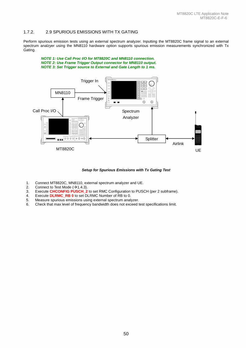
MT8820C LTE Application Note MT8820C-E-F-6
50
1.7.2. 2.9 SPURIOUS EMISSIONS WITH TX GATING Perform spurious emission tests using an external spectrum analyzer. Inputting the MT8820C frame signal to an external spectrum analzyer using the MN8110 hardware option supports spurious emission measurements synchronized with Tx Gating. NOTE 1: Use Call Proc I/O for MT8820C and MN8110 connection. NOTE 2: Use Frame Trigger Output connector for MN8110 output. NOTE 3: Set Trigger source to External and Gate Length to 1 ms.
Frame Trigger
MT8820C
321
654
987
#0*
UE
Airlink
Anrits
u
MT882 0 A
Anritsu MS2691A
Spectrum
Analyzer
MN8110
Splitter
Call Proc I/O
Trigger In
Setup for Spurious Emissions with Tx Gating Test
1. Connect MT8820C, MN8110, external spectrum analyzer and UE. 2. Connect to Test Mode (1.4.3). 3. Execute CHCONFIG PUSCH_2 to set RMC Configuration to PUSCH (per 2 subframe). 4. Execute DLRMC_RB 0 to set DLRMC Number of RB to 0.
5. Measure spurious emissions using external spectrum analyzer. 6. Check that max level of frequency bandwidth does not exceed test specifications limit.
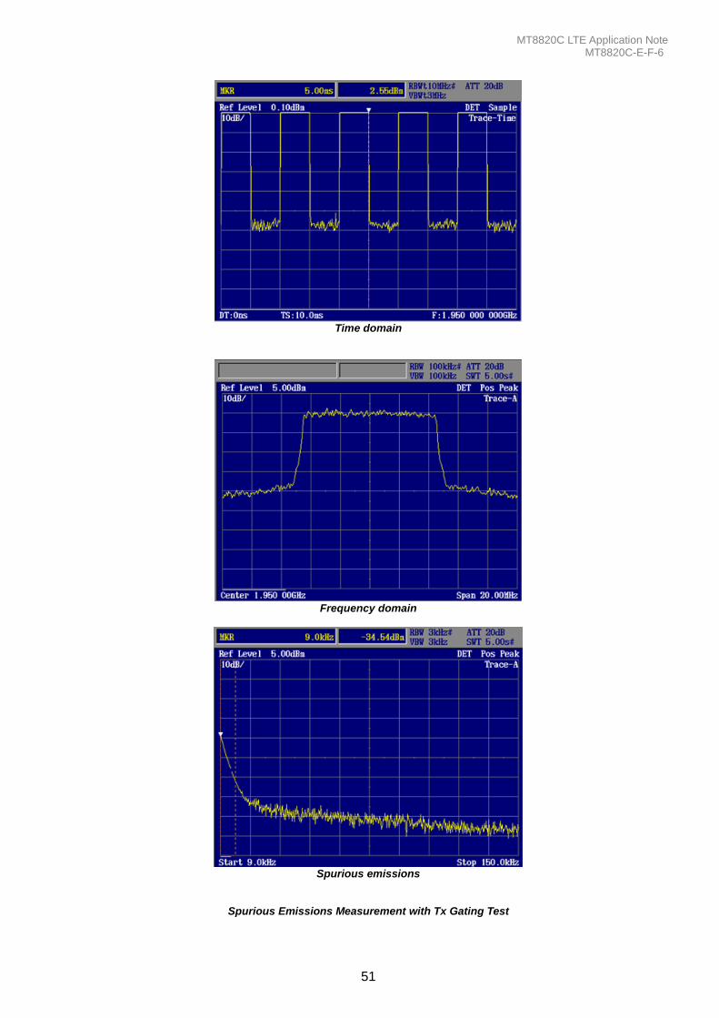
MT8820C LTE Application Note MT8820C-E-F-6
51
Time domain
Frequency domain
Spurious emissions
Spurious Emissions Measurement with Tx Gating Test
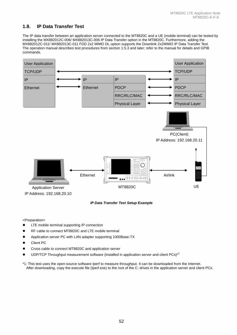
MT8820C LTE Application Note MT8820C-E-F-6
52
1.8. IP Data Transfer Test The IP data transfer between an application server connected to the MT8820C and a UE (mobile terminal) can be tested by installing the MX882012C-006/ MX882013C-006 IP Data Transfer option in the MT8820C. Furthermore, adding the MX882012C-011/ MX882013C-011 FDD 2x2 MIMO DL option supports the Downlink 2x2MIMO IP Data Transfer Test. The operation manual describes test procedures from section 1.5.3 and later; refer to the manual for details and GPIB commands.
Ethernet
IP
TCP/UDP
User Application
Physical Layer
RRC/RLC/MAC
PDCP
IP
Physical Layer
RRC/RLC/MAC
PDCP
IP
Ethernet
IP
TCP/UDP
User Application
MT8820C
321
654
987
#0*
PC(Client)
IP Address: 192.168.20.11
Application Server
IP Address: 192.168.20.10
Ethernet
UE
Airlink
Anrits
u
MT882 0 A
IP Data Transfer Test Setup Example
<Preparation>
LTE mobile terminal supporting IP connection
RF cable to connect MT8820C and LTE mobile terminal
Application server PC with LAN adapter supporting 1000Base-TX
Client PC
Cross cable to connect MT8820C and application server
UDP/TCP Throughput measurement software (installed in application server and client PCs)*1
*1: This test uses the open-source software Iperf to measure throughput. It can be downloaded from the Internet.
After downloading, copy the execute file (Iperf.exe) to the root of the C: drives in the application server and client PCs.
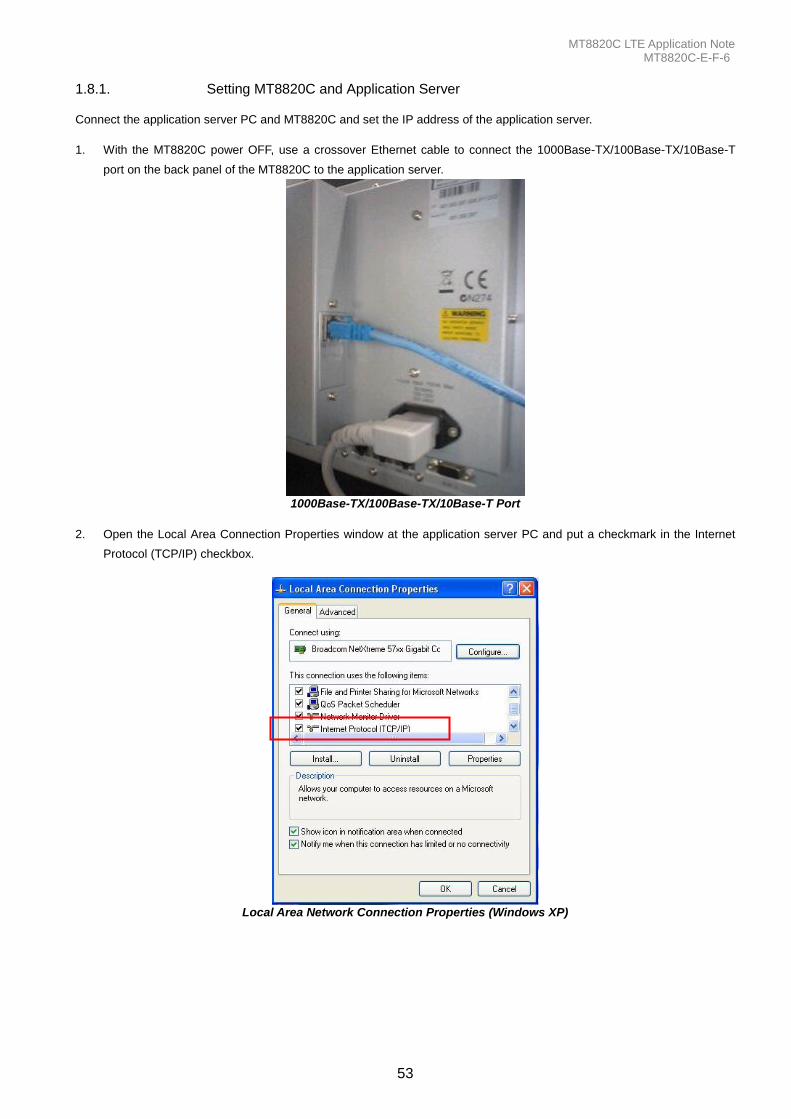
MT8820C LTE Application Note MT8820C-E-F-6
53
1.8.1. Setting MT8820C and Application Server Connect the application server PC and MT8820C and set the IP address of the application server.
1. With the MT8820C power OFF, use a crossover Ethernet cable to connect the 1000Base-TX/100Base-TX/10Base-T
port on the back panel of the MT8820C to the application server.
1000Base-TX/100Base-TX/10Base-T Port
2. Open the Local Area Connection Properties window at the application server PC and put a checkmark in the Internet
Protocol (TCP/IP) checkbox.
Local Area Network Connection Properties (Windows XP)
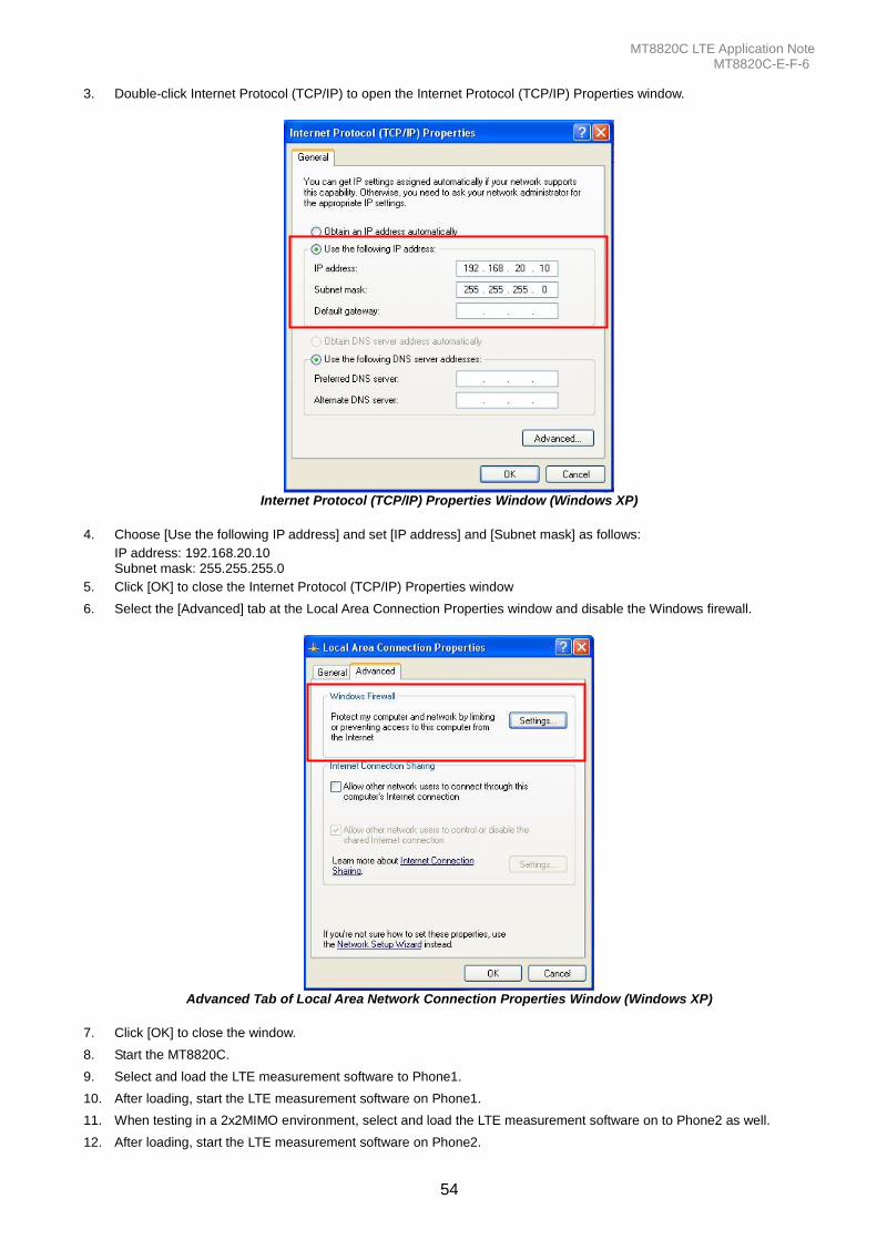
MT8820C LTE Application Note MT8820C-E-F-6
54
3. Double-click Internet Protocol (TCP/IP) to open the Internet Protocol (TCP/IP) Properties window.
Internet Protocol (TCP/IP) Properties Window (Windows XP)
4. Choose [Use the following IP address] and set [IP address] and [Subnet mask] as follows:
IP address: 192.168.20.10 Subnet mask: 255.255.255.0
5. Click [OK] to close the Internet Protocol (TCP/IP) Properties window
6. Select the [Advanced] tab at the Local Area Connection Properties window and disable the Windows firewall.
Advanced Tab of Local Area Network Connection Properties Window (Windows XP)
7. Click [OK] to close the window.
8. Start the MT8820C.
9. Select and load the LTE measurement software to Phone1.
10. After loading, start the LTE measurement software on Phone1.
11. When testing in a 2x2MIMO environment, select and load the LTE measurement software on to Phone2 as well.
12. After loading, start the LTE measurement software on Phone2.
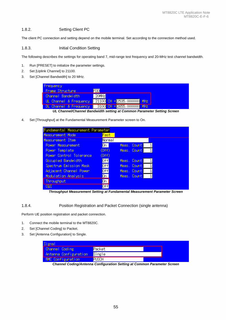
MT8820C LTE Application Note MT8820C-E-F-6
55
1.8.2. Setting Client PC The client PC connection and setting depend on the mobile terminal. Set according to the connection method used.
1.8.3. Initial Condition Setting The following describes the settings for operating band 7, mid-range test frequency and 20-MHz test channel bandwidth.
1. Run [PRESET] to initialize the parameter settings.
2. Set [Uplink Channel] to 21100.
3. Set [Channel Bandwidth] to 20 MHz.
UL Channel/Channel Bandwidth setting at Common Parameter Setting Screen
4. Set [Throughput] at the Fundamental Measurement Parameter screen to On.
Throughput Measurement Setting at Fundamental Measurement Parameter Screen
1.8.4. Position Registration and Packet Connection (single antenna) Perform UE position registration and packet connection.
1. Connect the mobile terminal to the MT8820C.
2. Set [Channel Coding] to Packet.
3. Set [Antenna Configuration] to Single.
Channel Coding/Antenna Configuration Setting at Common Parameter Screen
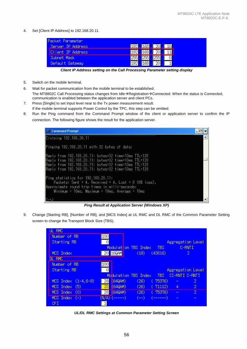
MT8820C LTE Application Note MT8820C-E-F-6
56
4. Set [Client IP Address] to 192.168.20.11.
Client IP Address setting on the Call Processing Parameter setting display
5. Switch on the mobile terminal.
6. Wait for packet communication from the mobile terminal to be established.
The MT8802C Call Processing status changes from IdleRegistrationConnected. When the status is Connected, communication is enabled between the application server and client PCs.
7. Press [Single] to set Input level near to the Tx power measurement result.
If the mobile terminal supports Power Control by the TPC, this step can be omitted.
8. Run the Ping command from the Command Prompt window of the client or application server to confirm the IP
connection. The following figure shows the result for the application server.
Ping Result at Application Server (Windows XP)
9. Change [Starting RB], [Number of RB], and [MCS Index] at UL RMC and DL RMC of the Common Parameter Setting
screen to change the Transport Block Size (TBS).
UL/DL RMC Settings at Common Parameter Setting Screen
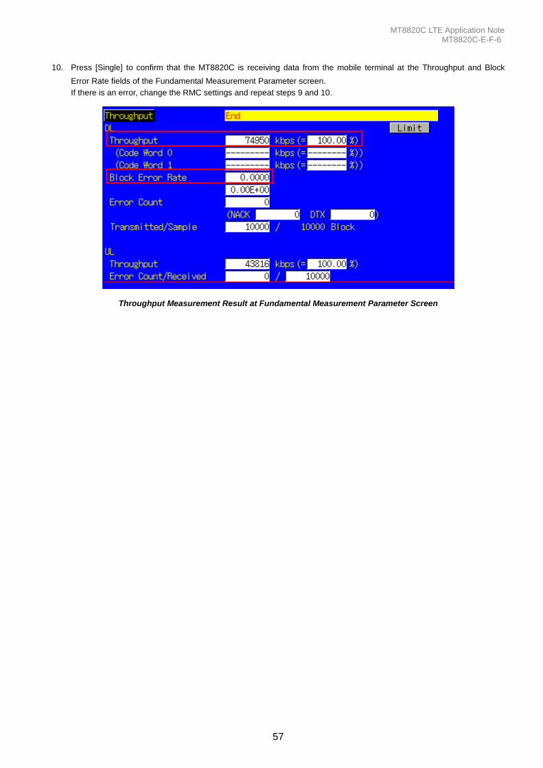
MT8820C LTE Application Note MT8820C-E-F-6
57
10. Press [Single] to confirm that the MT8820C is receiving data from the mobile terminal at the Throughput and Block
Error Rate fields of the Fundamental Measurement Parameter screen.
If there is an error, change the RMC settings and repeat steps 9 and 10.
Throughput Measurement Result at Fundamental Measurement Parameter Screen
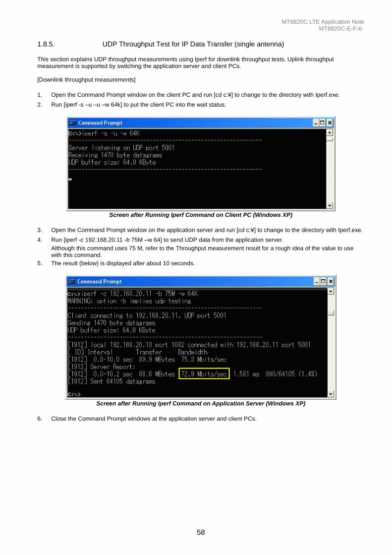
MT8820C LTE Application Note MT8820C-E-F-6
58
1.8.5. UDP Throughput Test for IP Data Transfer (single antenna) This section explains UDP throughput measurements using Iperf for downlink throughput tests. Uplink throughput measurement is supported by switching the application server and client PCs. [Downlink throughput measurements]
1. Open the Command Prompt window on the client PC and run [cd c:¥] to change to the directory with Iperf.exe.
2. Run [iperf -s –u –u –w 64k] to put the client PC into the wait status.
Screen after Running Iperf Command on Client PC (Windows XP)
3. Open the Command Prompt window on the application server and run [cd c:¥] to change to the directory with Iperf.exe.
4. Run [iperf -c 192.168.20.11 -b 75M –w 64] to send UDP data from the application server.
Although this command uses 75 M, refer to the Throughput measurement result for a rough idea of the value to use with this command.
5. The result (below) is displayed after about 10 seconds.
Screen after Running Iperf Command on Application Server (Windows XP)
6. Close the Command Prompt windows at the application server and client PCs.
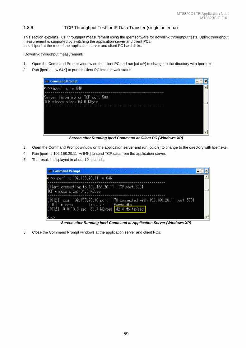
MT8820C LTE Application Note MT8820C-E-F-6
59
1.8.6. TCP Throughput Test for IP Data Transfer (single antenna) This section explains TCP throughput measurement using the Iperf software for downlink throughput tests. Uplink throughput measurement is supported by switching the application server and client PCs. Install Iperf at the root of the application server and client PC hard disks. [Downlink throughput measurement]
1. Open the Command Prompt window on the client PC and run [cd c:¥] to change to the directory with Iperf.exe.
2. Run [iperf -s –w 64K] to put the client PC into the wait status.
Screen after Running Iperf Command at Client PC (Windows XP)
3. Open the Command Prompt window on the application server and run [cd c:¥] to change to the directory with Iperf.exe.
4. Run [iperf -c 192.168.20.11 -w 64K] to send TCP data from the application server.
5. The result is displayed in about 10 seconds.
Screen after Running Iperf Command at Application Server (Windows XP)
6. Close the Command Prompt windows at the application server and client PCs.
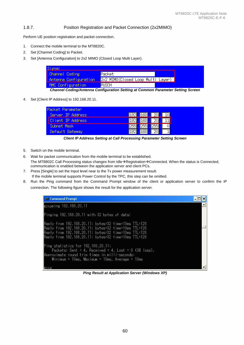
MT8820C LTE Application Note MT8820C-E-F-6
60
1.8.7. Position Registration and Packet Connection (2x2MIMO) Perform UE position registration and packet connection.
1. Connect the mobile terminal to the MT8820C.
2. Set [Channel Coding] to Packet.
3. Set [Antenna Configuration] to 2x2 MIMO (Closed Loop Multi Layer).
Channel Coding/Antenna Configuration Setting at Common Parameter Setting Screen
4. Set [Client IP Address] to 192.168.20.11.
Client IP Address Setting at Call Processing Parameter Setting Screen
5. Switch on the mobile terminal.
6. Wait for packet communication from the mobile terminal to be established.
The MT8802C Call Processing status changes from IdleRegistrationConnected. When the status is Connected, communication is enabled between the application server and client PCs.
7. Press [Single] to set the Input level near to the Tx power measurement result.
If the mobile terminal supports Power Control by the TPC, this step can be omitted.
8. Run the Ping command from the Command Prompt window of the client or application server to confirm the IP
connection. The following figure shows the result for the application server.
Ping Result at Application Server (Windows XP)
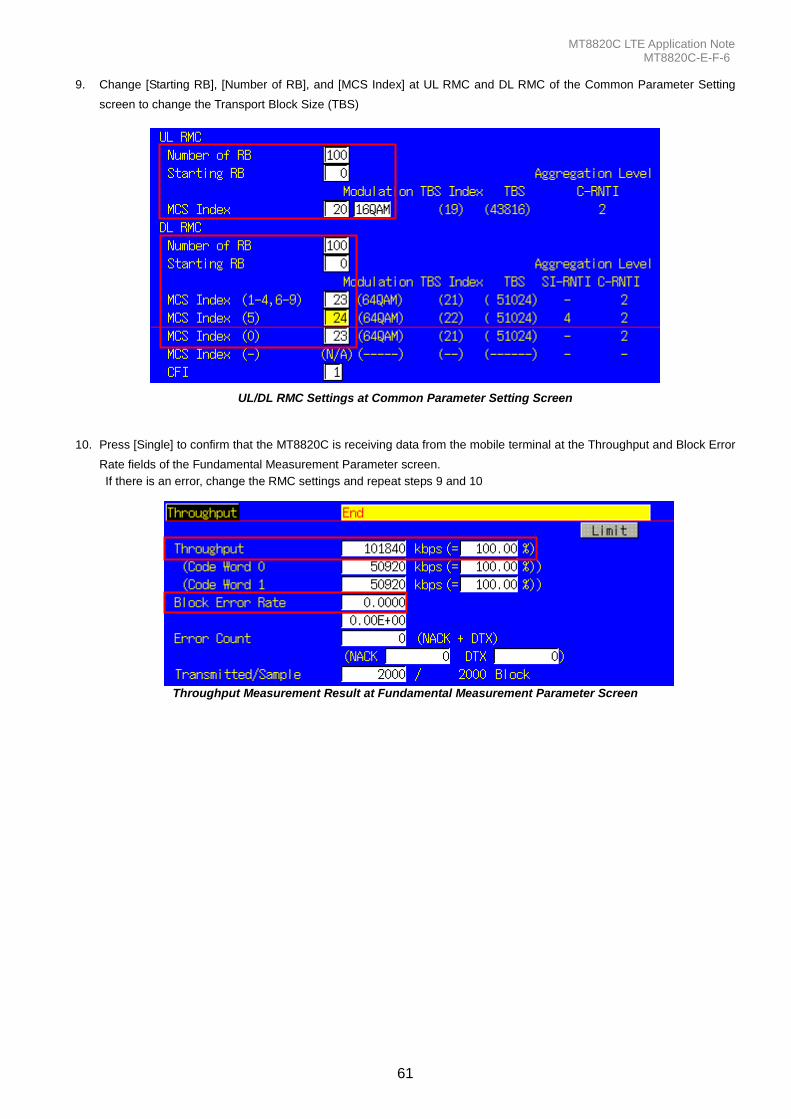
MT8820C LTE Application Note MT8820C-E-F-6
61
9. Change [Starting RB], [Number of RB], and [MCS Index] at UL RMC and DL RMC of the Common Parameter Setting
screen to change the Transport Block Size (TBS)
UL/DL RMC Settings at Common Parameter Setting Screen
10. Press [Single] to confirm that the MT8820C is receiving data from the mobile terminal at the Throughput and Block Error
Rate fields of the Fundamental Measurement Parameter screen.
If there is an error, change the RMC settings and repeat steps 9 and 10
Throughput Measurement Result at Fundamental Measurement Parameter Screen
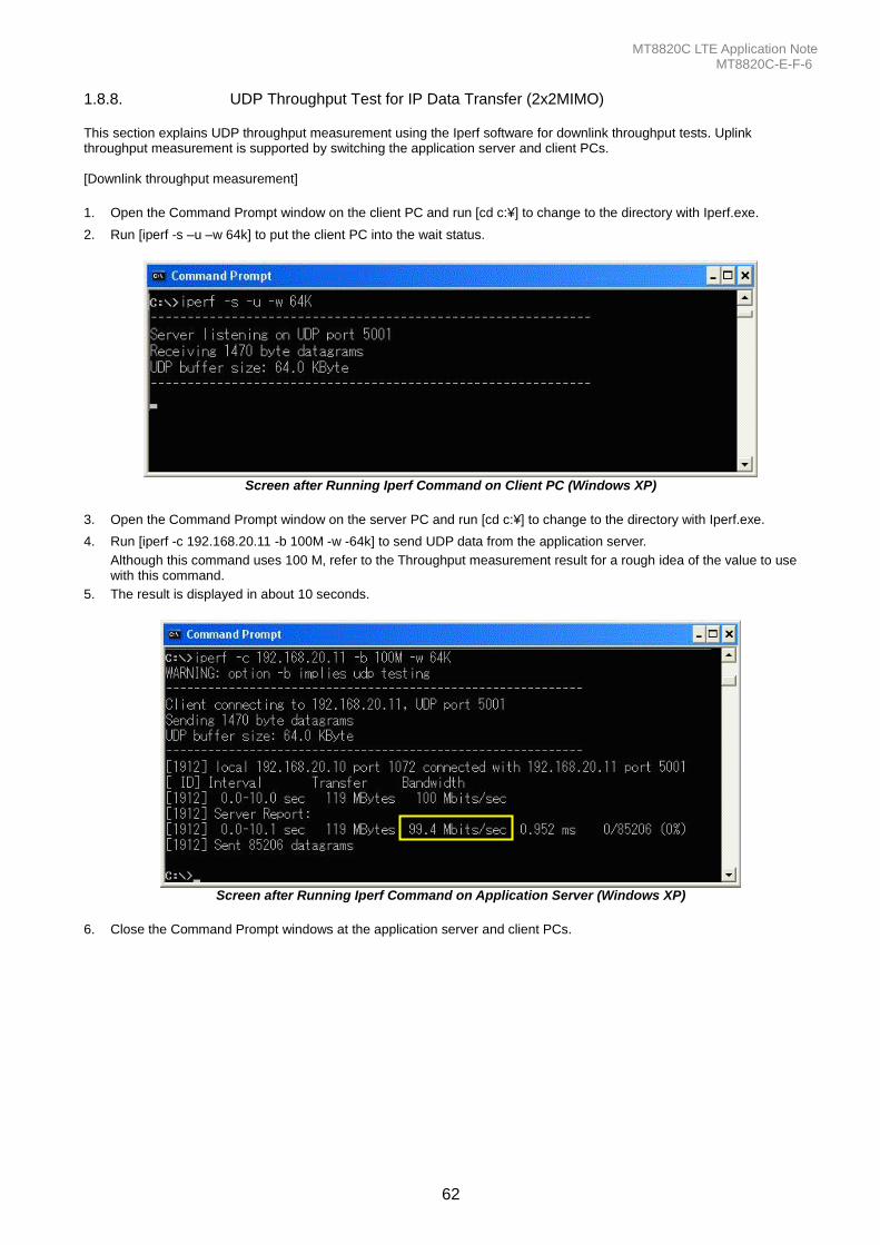
MT8820C LTE Application Note MT8820C-E-F-6
62
1.8.8. UDP Throughput Test for IP Data Transfer (2x2MIMO) This section explains UDP throughput measurement using the Iperf software for downlink throughput tests. Uplink throughput measurement is supported by switching the application server and client PCs. [Downlink throughput measurement]
1. Open the Command Prompt window on the client PC and run [cd c:¥] to change to the directory with Iperf.exe.
2. Run [iperf -s –u –w 64k] to put the client PC into the wait status.
Screen after Running Iperf Command on Client PC (Windows XP)
3. Open the Command Prompt window on the server PC and run [cd c:¥] to change to the directory with Iperf.exe.
4. Run [iperf -c 192.168.20.11 -b 100M -w -64k] to send UDP data from the application server.
Although this command uses 100 M, refer to the Throughput measurement result for a rough idea of the value to use with this command.
5. The result is displayed in about 10 seconds.
Screen after Running Iperf Command on Application Server (Windows XP)
6. Close the Command Prompt windows at the application server and client PCs.
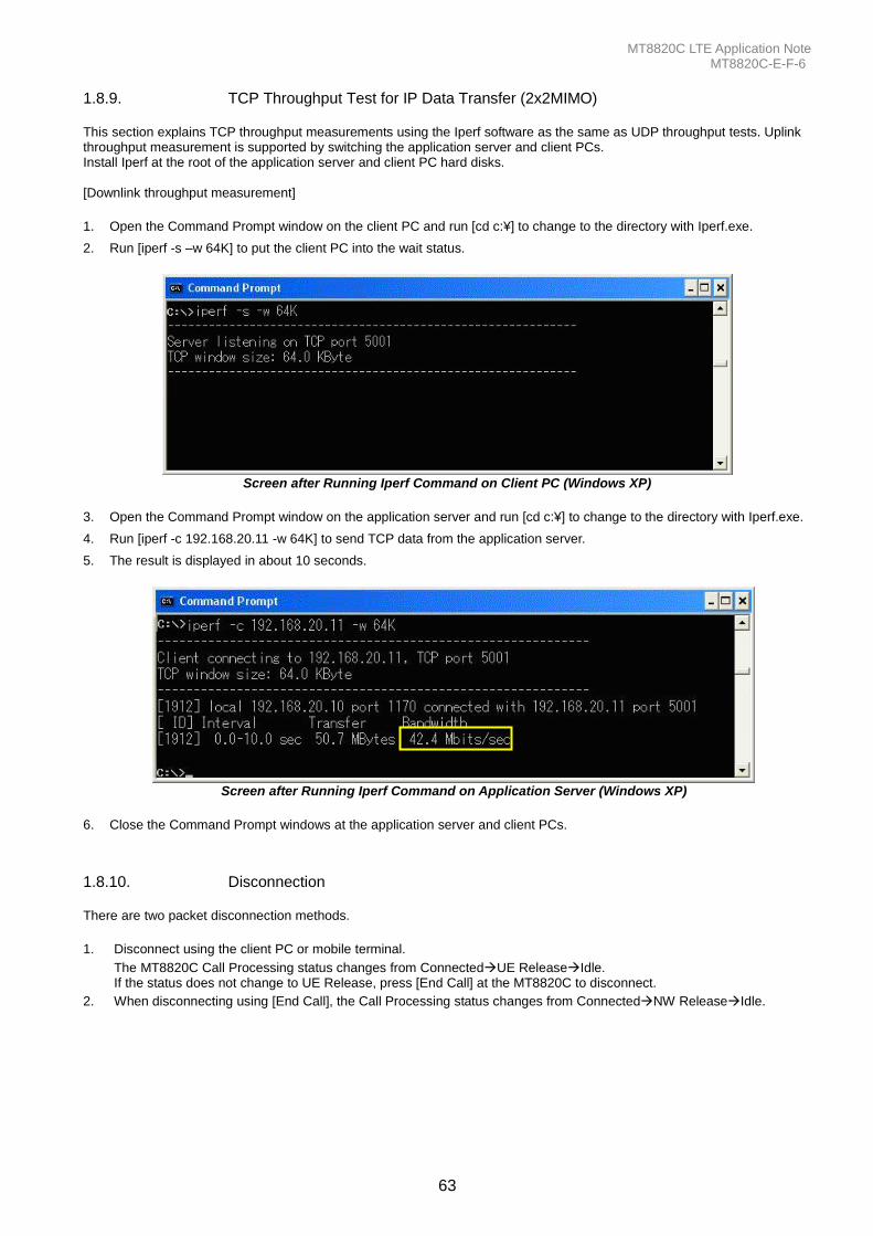
MT8820C LTE Application Note MT8820C-E-F-6
63
1.8.9. TCP Throughput Test for IP Data Transfer (2x2MIMO) This section explains TCP throughput measurements using the Iperf software as the same as UDP throughput tests. Uplink throughput measurement is supported by switching the application server and client PCs. Install Iperf at the root of the application server and client PC hard disks. [Downlink throughput measurement]
1. Open the Command Prompt window on the client PC and run [cd c:¥] to change to the directory with Iperf.exe.
2. Run [iperf -s –w 64K] to put the client PC into the wait status.
Screen after Running Iperf Command on Client PC (Windows XP)
3. Open the Command Prompt window on the application server and run [cd c:¥] to change to the directory with Iperf.exe.
4. Run [iperf -c 192.168.20.11 -w 64K] to send TCP data from the application server.
5. The result is displayed in about 10 seconds.
Screen after Running Iperf Command on Application Server (Windows XP)
6. Close the Command Prompt windows at the application server and client PCs.
1.8.10. Disconnection There are two packet disconnection methods.
1. Disconnect using the client PC or mobile terminal.
The MT8820C Call Processing status changes from ConnectedUE ReleaseIdle. If the status does not change to UE Release, press [End Call] at the MT8820C to disconnect.
2. When disconnecting using [End Call], the Call Processing status changes from ConnectedNW ReleaseIdle.
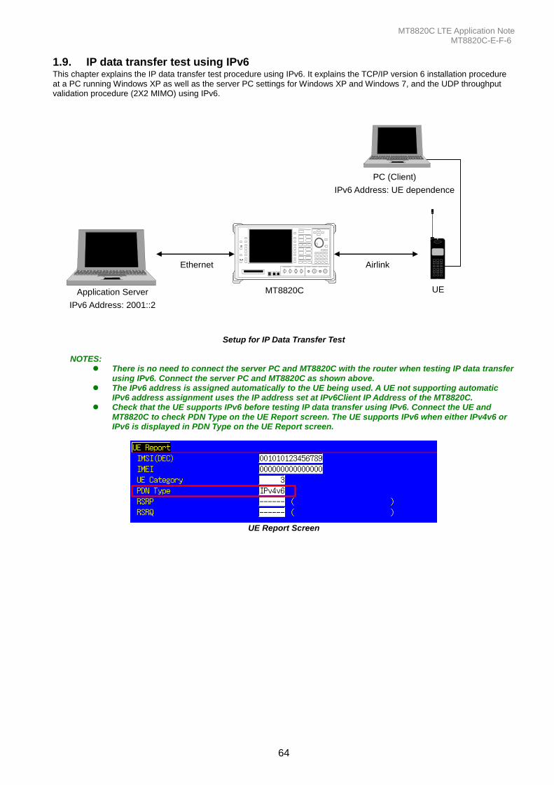
MT8820C LTE Application Note MT8820C-E-F-6
64
1.9. IP data transfer test using IPv6 This chapter explains the IP data transfer test procedure using IPv6. It explains the TCP/IP version 6 installation procedure at a PC running Windows XP as well as the server PC settings for Windows XP and Windows 7, and the UDP throughput validation procedure (2X2 MIMO) using IPv6.
MT8820C
321
654
987
#0*
PC (Client)
IPv6 Address: UE dependence
Application Server
IPv6 Address: 2001::2
Ethernet
UE
Airlink
Anrits
u
MT882 0 A
Setup for IP Data Transfer Test
NOTES:
There is no need to connect the server PC and MT8820C with the router when testing IP data transfer using IPv6. Connect the server PC and MT8820C as shown above.
The IPv6 address is assigned automatically to the UE being used. A UE not supporting automatic IPv6 address assignment uses the IP address set at IPv6Client IP Address of the MT8820C.
Check that the UE supports IPv6 before testing IP data transfer using IPv6. Connect the UE and MT8820C to check PDN Type on the UE Report screen. The UE supports IPv6 when either IPv4v6 or IPv6 is displayed in PDN Type on the UE Report screen.
UE Report Screen
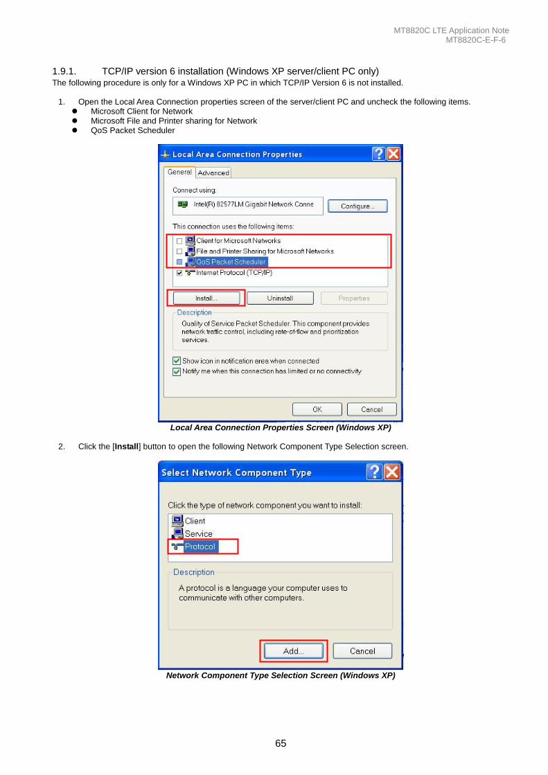
MT8820C LTE Application Note MT8820C-E-F-6
65
1.9.1. TCP/IP version 6 installation (Windows XP server/client PC only) The following procedure is only for a Windows XP PC in which TCP/IP Version 6 is not installed.
1. Open the Local Area Connection properties screen of the server/client PC and uncheck the following items. Microsoft Client for Network Microsoft File and Printer sharing for Network QoS Packet Scheduler
Local Area Connection Properties Screen (Windows XP)
2. Click the [Install] button to open the following Network Component Type Selection screen.
Network Component Type Selection Screen (Windows XP)

MT8820C LTE Application Note MT8820C-E-F-6
66
3. Select [Protocol] and click the [Add] button to open the following Network Protocol Selection screen.
Network Protocol Selection Screen (Windows XP)
4. Select [Microsoft TCP/IP version 6] and click the [OK] button to complete the TCP/IP version 6 installation.
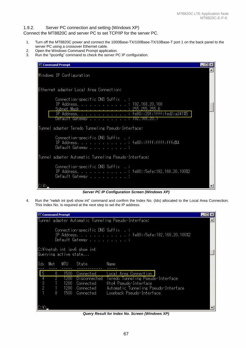
MT8820C LTE Application Note MT8820C-E-F-6
67
1.9.2. Server PC connection and setting (Windows XP)
Connect the MT8820C and server PC to set TCP/IP for the server PC.
1. Turn off the MT8820C power and connect the 1000Base-TX/100Base-TX/10Base-T port 1 on the back panel to the server PC using a crossover Ethernet cable.
2. Open the Windows Command Prompt application. 3. Run the “ipconfig” command to check the server PC IP configuration.
Server PC IP Configuration Screen (Windows XP)
4. Run the “netsh int ipv6 show int” command and confirm the Index No. (Idx) allocated to the Local Area Connection. This Index No. is required at the next step to set the IP address.
Query Result for Index No. Screen (Windows XP)
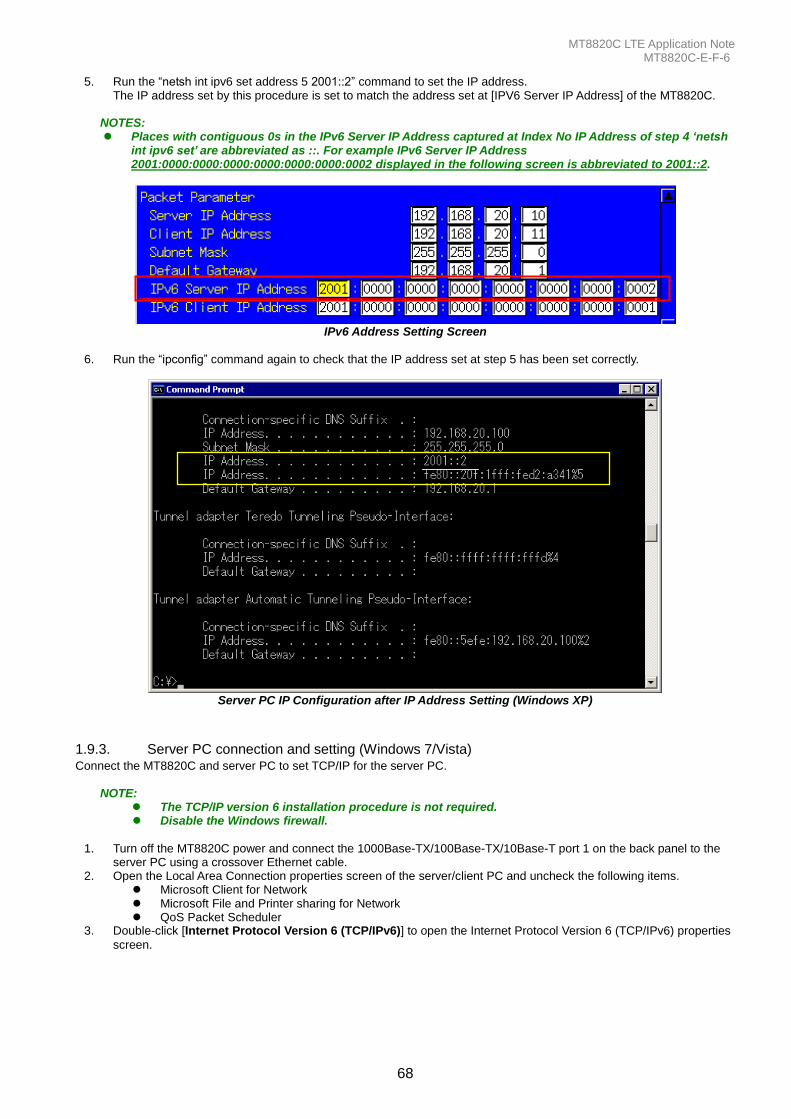
MT8820C LTE Application Note MT8820C-E-F-6
68
5. Run the “netsh int ipv6 set address 5 2001::2” command to set the IP address. The IP address set by this procedure is set to match the address set at [IPV6 Server IP Address] of the MT8820C.
NOTES: Places with contiguous 0s in the IPv6 Server IP Address captured at Index No IP Address of step 4 ‘netsh
int ipv6 set’ are abbreviated as ::. For example IPv6 Server IP Address 2001:0000:0000:0000:0000:0000:0000:0002 displayed in the following screen is abbreviated to 2001::2.
IPv6 Address Setting Screen
6. Run the “ipconfig” command again to check that the IP address set at step 5 has been set correctly.
Server PC IP Configuration after IP Address Setting (Windows XP)
1.9.3. Server PC connection and setting (Windows 7/Vista) Connect the MT8820C and server PC to set TCP/IP for the server PC.
NOTE: The TCP/IP version 6 installation procedure is not required. Disable the Windows firewall.
1. Turn off the MT8820C power and connect the 1000Base-TX/100Base-TX/10Base-T port 1 on the back panel to the
server PC using a crossover Ethernet cable. 2. Open the Local Area Connection properties screen of the server/client PC and uncheck the following items.
Microsoft Client for Network Microsoft File and Printer sharing for Network QoS Packet Scheduler
3. Double-click [Internet Protocol Version 6 (TCP/IPv6)] to open the Internet Protocol Version 6 (TCP/IPv6) properties
screen.
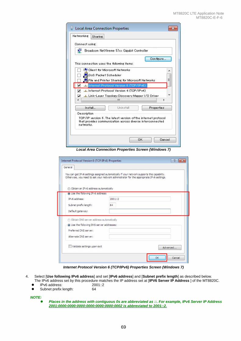
MT8820C LTE Application Note MT8820C-E-F-6
69
Local Area Connection Properties Screen (Windows 7)
Internet Protocol Version 6 (TCP/IPv6) Properties Screen (Windows 7)
4. Select [Use following IPv6 address] and set [IPv6 address] and [Subnet prefix length] as described below.
The IPv6 address set by this procedure matches the IP address set at [IPV6 Server IP Address ] of the MT8820C.
IPv6 address: 2001::2 Subnet prefix length: 64
NOTE:
Places in the address with contiguous 0s are abbreviated as ::. For example, IPv6 Server IP Address 2001:0000:0000:0000:0000:0000:0000:0002 is abbreviated to 2001::2.
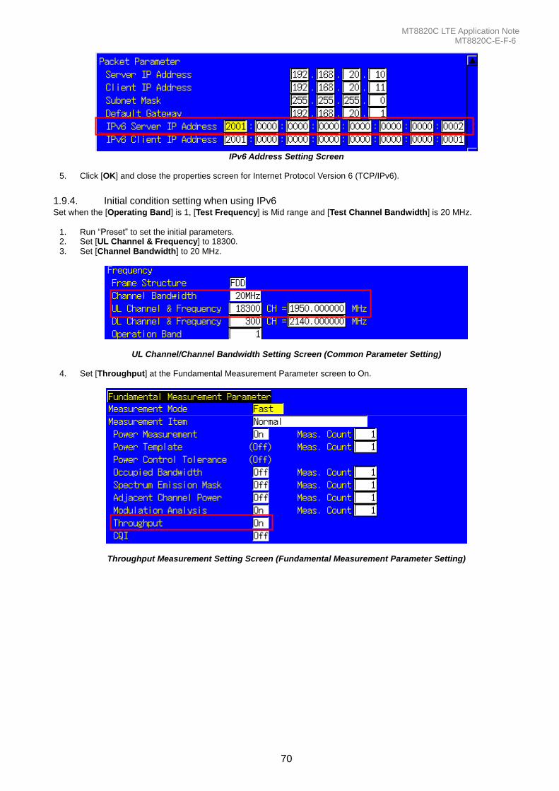
MT8820C LTE Application Note MT8820C-E-F-6
70
IPv6 Address Setting Screen
5. Click [OK] and close the properties screen for Internet Protocol Version 6 (TCP/IPv6).
1.9.4. Initial condition setting when using IPv6 Set when the [Operating Band] is 1, [Test Frequency] is Mid range and [Test Channel Bandwidth] is 20 MHz.
1. Run “Preset” to set the initial parameters. 2. Set [UL Channel & Frequency] to 18300. 3. Set [Channel Bandwidth] to 20 MHz.
UL Channel/Channel Bandwidth Setting Screen (Common Parameter Setting)
4. Set [Throughput] at the Fundamental Measurement Parameter screen to On.
Throughput Measurement Setting Screen (Fundamental Measurement Parameter Setting)
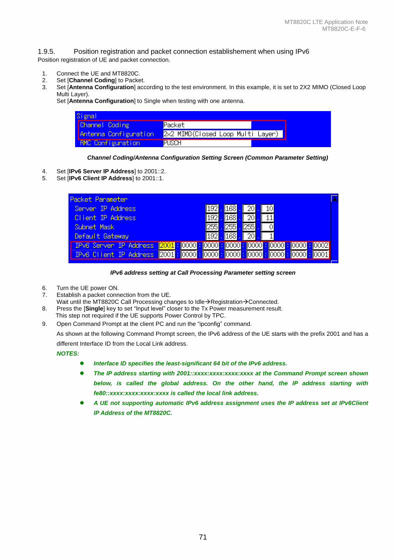
MT8820C LTE Application Note MT8820C-E-F-6
71
1.9.5. Position registration and packet connection establishement when using IPv6 Position registration of UE and packet connection.
1. Connect the UE and MT8820C. 2. Set [Channel Coding] to Packet. 3. Set [Antenna Configuration] according to the test environment. In this example, it is set to 2X2 MIMO (Closed Loop
Multi Layer). Set [Antenna Configuration] to Single when testing with one antenna.
Channel Coding/Antenna Configuration Setting Screen (Common Parameter Setting)
4. Set [IPv6 Server IP Address] to 2001::2. 5. Set [IPv6 Client IP Address] to 2001::1.
IPv6 address setting at Call Processing Parameter setting screen
6. Turn the UE power ON. 7. Establish a packet connection from the UE.
Wait until the MT8820C Call Processing changes to IdleRegistrationConnected. 8. Press the [Single] key to set “Input level” closer to the Tx Power measurement result.
This step not required if the UE supports Power Control by TPC.
9. Open Command Prompt at the client PC and run the “ipconfig” command.
As shown at the following Command Prompt screen, the IPv6 address of the UE starts with the prefix 2001 and has a
different Interface ID from the Local Link address.
NOTES:
Interface ID specifies the least-significant 64 bit of the IPv6 address.
The IP address starting with 2001::xxxx:xxxx:xxxx:xxxx at the Command Prompt screen shown
below, is called the global address. On the other hand, the IP address starting with
fe80::xxxx:xxxx:xxxx:xxxx is called the local link address.
A UE not supporting automatic IPv6 address assignment uses the IP address set at IPv6Client
IP Address of the MT8820C.
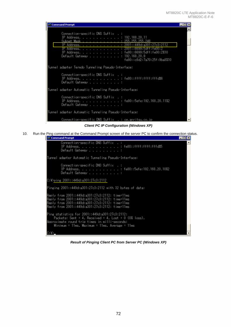
MT8820C LTE Application Note MT8820C-E-F-6
72
Client PC IP Configuration (Windows XP)
10. Run the Ping command at the Command Prompt screen of the server PC to confirm the connection status.
Result of Pinging Client PC from Server PC (Windows XP)
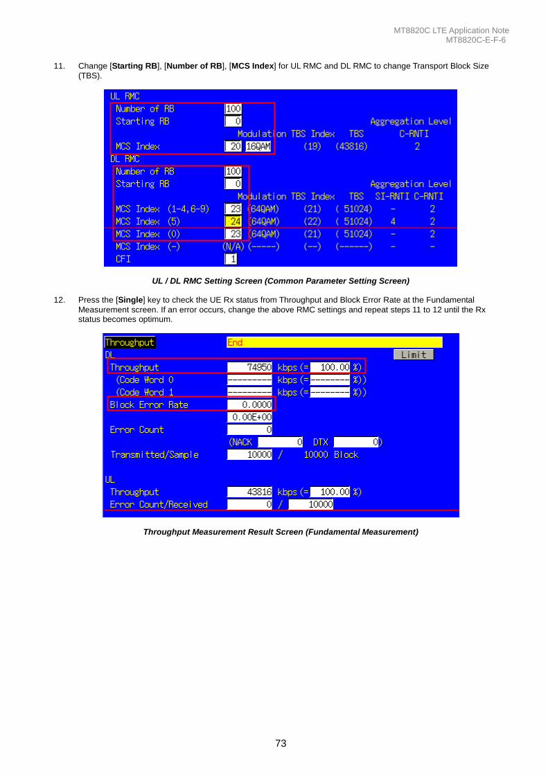
MT8820C LTE Application Note MT8820C-E-F-6
73
11. Change [Starting RB], [Number of RB], [MCS Index] for UL RMC and DL RMC to change Transport Block Size
(TBS).
UL / DL RMC Setting Screen (Common Parameter Setting Screen) 12. Press the [Single] key to check the UE Rx status from Throughput and Block Error Rate at the Fundamental
Measurement screen. If an error occurs, change the above RMC settings and repeat steps 11 to 12 until the Rx status becomes optimum.
Throughput Measurement Result Screen (Fundamental Measurement)
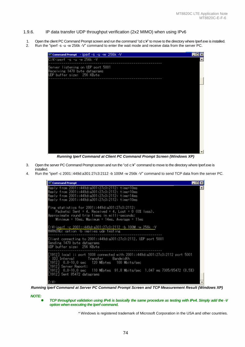
MT8820C LTE Application Note MT8820C-E-F-6
74
1.9.6. IP data transfer UDP throughput verification (2x2 MIMO) when using IPv6
1. Open the client PC Command Prompt screen and run the command “cd c:¥” to move to the directory where Iperf.exe is installed. 2. Run the “iperf -s -u -w 256k -V” command to enter the wait mode and receive data from the server PC.
Running Iperf Command at Client PC Command Prompt Screen (Windows XP)
3. Open the server PC Command Prompt screen and run the “cd c:¥” command to move to the directory where Iperf.exe is
installed. 4. Run the “iperf -c 2001::449d:a301:27c3:2112 -b 100M -w 256k -V” command to send TCP data from the server PC.
Running Iperf Command at Server PC Command Prompt Screen and TCP Measurement Result (Windows XP) NOTE:
TCP throughput validation using IPv6 is basically the same procedure as testing with IPv4. Simply add the -V option when executing the Iperf command.
* Windows is registered trademark of Microsoft Corporation in the USA and other countries.
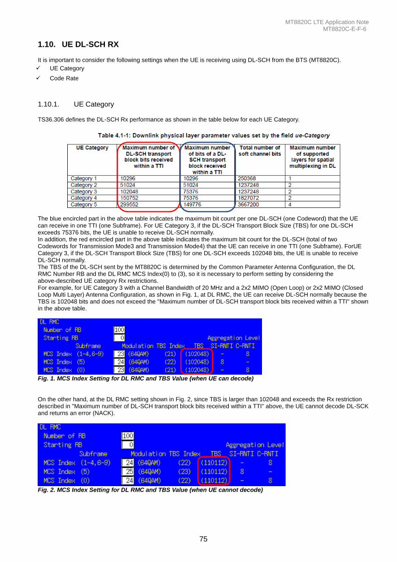
MT8820C LTE Application Note MT8820C-E-F-6
75
1.10. UE DL-SCH RX It is important to consider the following settings when the UE is receiving using DL-SCH from the BTS (MT8820C).
UE Category
Code Rate
1.10.1. UE Category TS36.306 defines the DL-SCH Rx performance as shown in the table below for each UE Category.
The blue encircled part in the above table indicates the maximum bit count per one DL-SCH (one Codeword) that the UE can receive in one TTI (one Subframe). For UE Category 3, if the DL-SCH Transport Block Size (TBS) for one DL-SCH exceeds 75376 bits, the UE is unable to receive DL-SCH normally. In addition, the red encircled part in the above table indicates the maximum bit count for the DL-SCH (total of two Codewords for Transmission Mode3 and Transmission Mode4) that the UE can receive in one TTI (one Subframe). ForUE Category 3, if the DL-SCH Transport Block Size (TBS) for one DL-SCH exceeds 102048 bits, the UE is unable to receive DL-SCH normally. The TBS of the DL-SCH sent by the MT8820C is determined by the Common Parameter Antenna Configuration, the DL RMC Number RB and the DL RMC MCS Index(0) to (3), so it is necessary to perform setting by considering the above-described UE category Rx restrictions. For example, for UE Category 3 with a Channel Bandwidth of 20 MHz and a 2x2 MIMO (Open Loop) or 2x2 MIMO (Closed Loop Multi Layer) Antenna Configuration, as shown in Fig. 1, at DL RMC, the UE can receive DL-SCH normally because the TBS is 102048 bits and does not exceed the "Maximum number of DL-SCH transport block bits received within a TTI" shown in the above table.
Fig. 1. MCS Index Setting for DL RMC and TBS Value (when UE can decode) On the other hand, at the DL RMC setting shown in Fig. 2, since TBS is larger than 102048 and exceeds the Rx restriction described in "Maximum number of DL-SCH transport block bits received within a TTI" above, the UE cannot decode DL-SCK and returns an error (NACK).
Fig. 2. MCS Index Setting for DL RMC and TBS Value (when UE cannot decode)

MT8820C LTE Application Note MT8820C-E-F-6
76
1.10.2. Code Rate
The LTE use data Tx channel (PDSCH-DLSCH) performs channel encode processing and adds the error correction coding required at decoding by the UE before mapping to the Physical Channel and sending. Since error correction encoding can be added as the ratio (Code Rate) between the Information Bit count (number of CRC bits added to TBS), which is the size of the user data, and the Physical Channel Bit count with PDSCH per Subframe becomes smaller, the Rx data error correction pereformance increases. The above described ratio (Code Rate) is defined below. Code Rate = Information Bit count/Physical Channel Bit count The 3GPP TS 36.213 7.1.7 Modulation order and transport block size determination notes that "The UE may skip decoding a transport block in an initial transmission if the effective channel code rate is higher than 0.930, where the effective channel code rate is defined as the number of downlink information bits (including CRC bits) divided by the number of physical channel bits on PDSCH". As a result, when the DL-SCH Code Rate sent from the BTS exceeds 0.93, the UE is unable to decode DL-SCH and returns an error (NACK).
Example: When Channel Coding = RMC and Antenna Config. = 2x2 MIMO (OpenLoop)
Tables 3 and 4 below show the MCS Index value and Code rate at Full RB Mapping for each bandwidth. Table 3 shows the value for Subframe #0 and Table 4 for Subframe #1-4, and #6-9. Depending on the MCS Index setting, sometimes the UE may be unable to decode DL-SCH if the Code Rate exceeds 0.930. Subframe #0 can be decoded by a smaller MCS Index than other subframes. As shown in Fig. 5, there are non-PDSCH Physical Channels PBCH, PSS, and SSS in Subframe #0, so the PDSCH region is smaller than other subframes. Table 3. Relationship between Subframe#0 MCS Index Value and Code Rate
Bandwidth CFI RB Physical
Channel bits MCS Index
TBS Information
bits Code Rate
UE can decode?
1.4 4 6 960
4 816 840 0.875 Yes
5 1008 1032 1.075 No
3 3 15 16920
23 14960 15032 0.8884 Yes
24 15984 16056 0.9489 No
5 3 25 31560
25 28224 28344 0.8981 Yes
26 30528 30648 0.9711 No
10 2 50 75360
27 63408 63672 0.8449 Yes
28 73392 73680 0.9777 No
15 2 75 115560
27 93776 94160 0.8148 Yes
28 110112 110544 0.9566 No
20 2 100 155760
27 127552 128056 0.8221 Yes
28 150752 151352 0.9717 No
The UE can decode DL-SCH at the MCS Index where the Code Rate is 0.930.
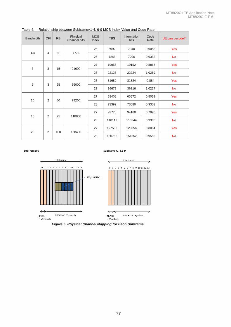
MT8820C LTE Application Note MT8820C-E-F-6
77
Table 4. Relationship between Subframe#1-4, 6-9 MCS Index Value and Code Rate
Bandwidth CFI RB Physical
Channel bits MCS Index
TBS Information
bits Code Rate
UE can decode?
1.4 4 6 7776
25 6992 7040 0.9053 Yes
26 7248 7296 0.9383 No
3 3 15 21600
27 19056 19152 0.8867 Yes
28 22128 22224 1.0289 No
5 3 25 36000
27 31680 31824 0.884 Yes
28 36672 36816 1.0227 No
10 2 50 79200
27 63408 63672 0.8039 Yes
28 73392 73680 0.9303 No
15 2 75 118800
27 93776 94160 0.7926 Yes
28 110112 110544 0.9305 No
20 2 100 158400
27 127552 128056 0.8084 Yes
28 150752 151352 0.9555 No
Figure 5. Physical Channel Mapping for Each Subframe
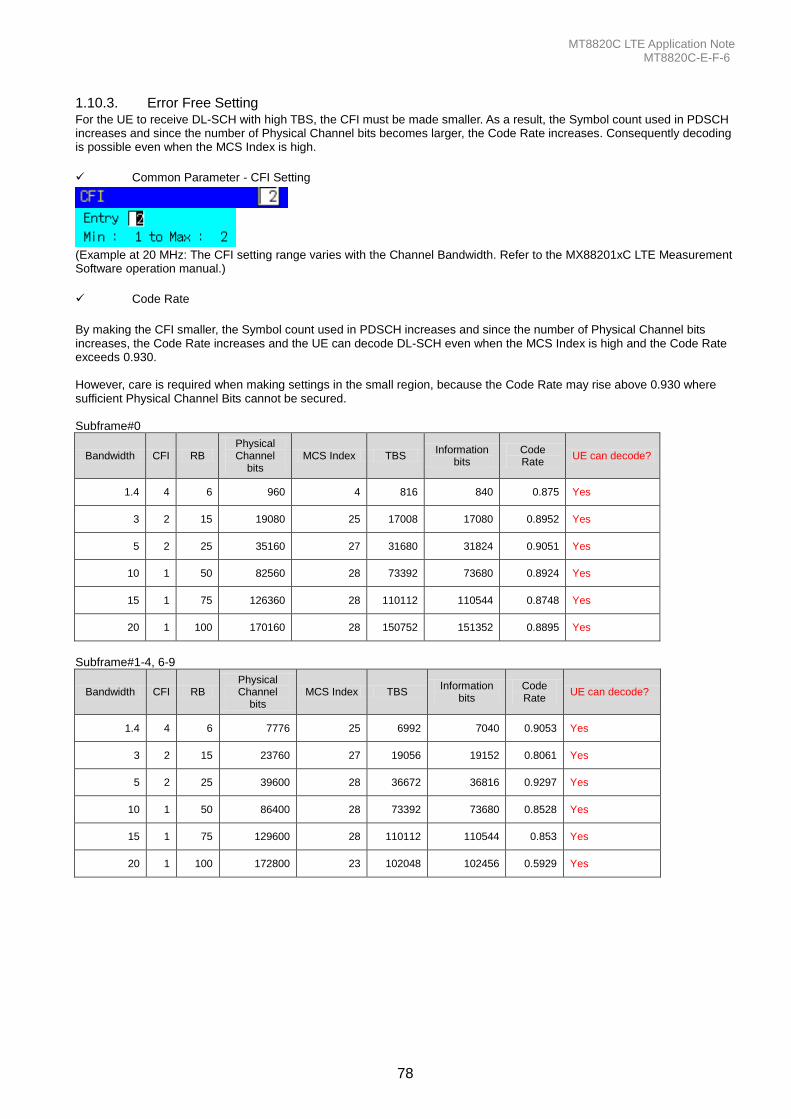
MT8820C LTE Application Note MT8820C-E-F-6
78
1.10.3. Error Free Setting For the UE to receive DL-SCH with high TBS, the CFI must be made smaller. As a result, the Symbol count used in PDSCH increases and since the number of Physical Channel bits becomes larger, the Code Rate increases. Consequently decoding is possible even when the MCS Index is high.
Common Parameter - CFI Setting
(Example at 20 MHz: The CFI setting range varies with the Channel Bandwidth. Refer to the MX88201xC LTE Measurement Software operation manual.)
Code Rate
By making the CFI smaller, the Symbol count used in PDSCH increases and since the number of Physical Channel bits increases, the Code Rate increases and the UE can decode DL-SCH even when the MCS Index is high and the Code Rate exceeds 0.930. However, care is required when making settings in the small region, because the Code Rate may rise above 0.930 where sufficient Physical Channel Bits cannot be secured. Subframe#0
Bandwidth CFI RB Physical Channel
bits MCS Index TBS
Information bits
Code Rate
UE can decode?
1.4 4 6 960 4 816 840 0.875 Yes
3 2 15 19080 25 17008 17080 0.8952 Yes
5 2 25 35160 27 31680 31824 0.9051 Yes
10 1 50 82560 28 73392 73680 0.8924 Yes
15 1 75 126360 28 110112 110544 0.8748 Yes
20 1 100 170160 28 150752 151352 0.8895 Yes
Subframe#1-4, 6-9
Bandwidth CFI RB Physical Channel
bits MCS Index TBS
Information bits
Code Rate
UE can decode?
1.4 4 6 7776 25 6992 7040 0.9053 Yes
3 2 15 23760 27 19056 19152 0.8061 Yes
5 2 25 39600 28 36672 36816 0.9297 Yes
10 1 50 86400 28 73392 73680 0.8528 Yes
15 1 75 129600 28 110112 110544 0.853 Yes
20 1 100 172800 23 102048 102456 0.5929 Yes

MT8820C LTE Application Note MT8820C-E-F-6
79
A. Annex: ARB Waveform List
A.1 ARB Waveform Installer Version: Q007
Packege1:LTE DL 10MHz
No. Pattern NameChannel
Bandwidth
UL
Number of RB
UL
Start RB
UL
Modulation
DL
Number of RB
DL
Start RB
DL
Modulation
Power
Control
Frame
Structure
0 UL R50 S0 QPSK UP 10 50 0 QPSK 50 0 QPSK All up FDD
1 UL R12 S0 QPSK UP 10 12 0 QPSK 50 0 QPSK All up FDD
2 UL R12 S38 QPSK UP 10 12 38 QPSK 50 0 QPSK All up FDD
3 UL R50 S0 16QAM UP 10 50 0 16QAM 50 0 QPSK All up FDD
4 UL R12 S38 16QAM UP 10 12 38 16QAM 50 0 QPSK All up FDD
5 UL R12 S0 16QAM UP 10 12 0 16QAM 50 0 QPSK All up FDD
6 UL R20 S0 QPSK UP 10 20 0 QPSK 50 0 QPSK All up FDD
7 void - - - - - - - - -
8 void - - - - - - - - -
9 void - - - - - - - - -
10 void - - - - - - - - -
11 void - - - - - - - - -
12 TDD UL R50 S0 QPSK UP 10 50 0 QPSK 50 0 QPSK All up TDD
13 TDD UL R12 S0 QPSK UP 10 12 0 QPSK 50 0 QPSK All up TDD
14 TDD UL R12 S38 QPSK UP 10 12 38 QPSK 50 0 QPSK All up TDD
15 TDD UL R50 S0 16QAM UP 10 50 0 16QAM 50 0 QPSK All up TDD
16 TDD UL R12 S38 16QAM UP 10 12 38 16QAM 50 0 QPSK All up TDD
17 TDD UL R12 S0 16QAM UP 10 12 0 16QAM 50 0 QPSK All up TDD
18 TDD UL R20 S0 QPSK UP 10 20 0 QPSK 50 0 QPSK All up TDD
19 void - - - - - - - - -
20 void - - - - - - - - -
21 void - - - - - - - - -
22 void - - - - - - - - -
23 void - - - - - - - - - Note1: TDD Uplink Downlink Configuration = 1, Special Subframe Configuration = 4 Note2: C-RNTI = AAAA(hex)
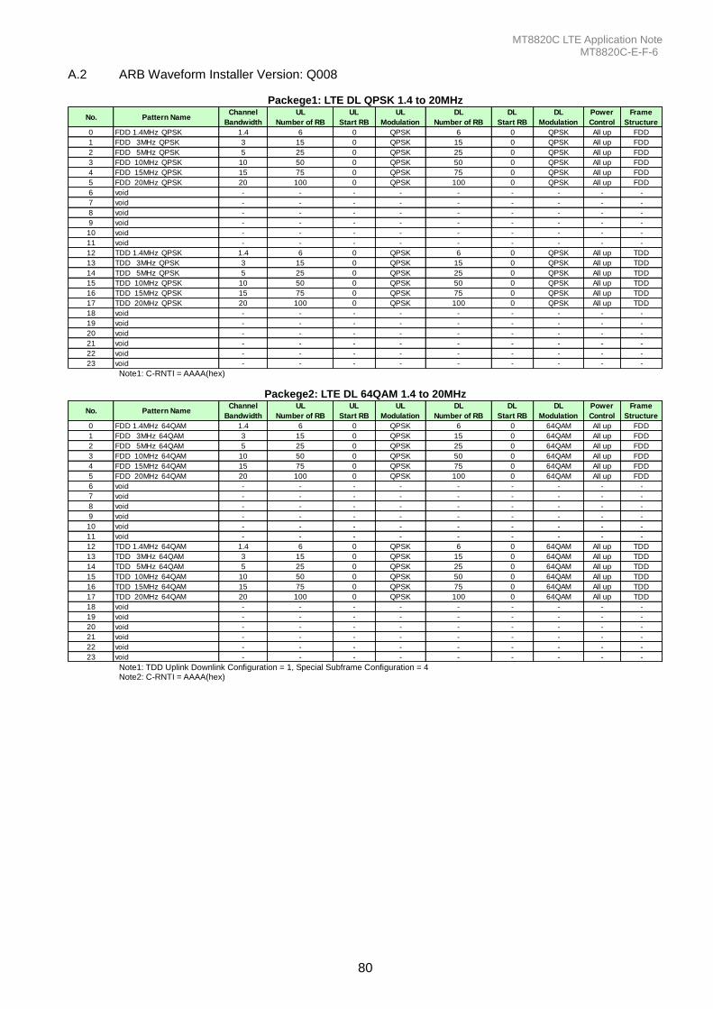
MT8820C LTE Application Note MT8820C-E-F-6
80
A.2 ARB Waveform Installer Version: Q008
Packege1: LTE DL QPSK 1.4 to 20MHz
No. Pattern NameChannel
Bandwidth
UL
Number of RB
UL
Start RB
UL
Modulation
DL
Number of RB
DL
Start RB
DL
Modulation
Power
Control
Frame
Structure
0 FDD 1.4MHz QPSK 1.4 6 0 QPSK 6 0 QPSK All up FDD
1 FDD 3MHz QPSK 3 15 0 QPSK 15 0 QPSK All up FDD
2 FDD 5MHz QPSK 5 25 0 QPSK 25 0 QPSK All up FDD
3 FDD 10MHz QPSK 10 50 0 QPSK 50 0 QPSK All up FDD
4 FDD 15MHz QPSK 15 75 0 QPSK 75 0 QPSK All up FDD
5 FDD 20MHz QPSK 20 100 0 QPSK 100 0 QPSK All up FDD
6 void - - - - - - - - -
7 void - - - - - - - - -
8 void - - - - - - - - -
9 void - - - - - - - - -
10 void - - - - - - - - -
11 void - - - - - - - - -
12 TDD 1.4MHz QPSK 1.4 6 0 QPSK 6 0 QPSK All up TDD
13 TDD 3MHz QPSK 3 15 0 QPSK 15 0 QPSK All up TDD
14 TDD 5MHz QPSK 5 25 0 QPSK 25 0 QPSK All up TDD
15 TDD 10MHz QPSK 10 50 0 QPSK 50 0 QPSK All up TDD
16 TDD 15MHz QPSK 15 75 0 QPSK 75 0 QPSK All up TDD
17 TDD 20MHz QPSK 20 100 0 QPSK 100 0 QPSK All up TDD
18 void - - - - - - - - -
19 void - - - - - - - - -
20 void - - - - - - - - -
21 void - - - - - - - - -
22 void - - - - - - - - -
23 void - - - - - - - - - Note1: C-RNTI = AAAA(hex)
Packege2: LTE DL 64QAM 1.4 to 20MHz
No. Pattern NameChannel
Bandwidth
UL
Number of RB
UL
Start RB
UL
Modulation
DL
Number of RB
DL
Start RB
DL
Modulation
Power
Control
Frame
Structure
0 FDD 1.4MHz 64QAM 1.4 6 0 QPSK 6 0 64QAM All up FDD
1 FDD 3MHz 64QAM 3 15 0 QPSK 15 0 64QAM All up FDD
2 FDD 5MHz 64QAM 5 25 0 QPSK 25 0 64QAM All up FDD
3 FDD 10MHz 64QAM 10 50 0 QPSK 50 0 64QAM All up FDD
4 FDD 15MHz 64QAM 15 75 0 QPSK 75 0 64QAM All up FDD
5 FDD 20MHz 64QAM 20 100 0 QPSK 100 0 64QAM All up FDD
6 void - - - - - - - - -
7 void - - - - - - - - -
8 void - - - - - - - - -
9 void - - - - - - - - -
10 void - - - - - - - - -
11 void - - - - - - - - -
12 TDD 1.4MHz 64QAM 1.4 6 0 QPSK 6 0 64QAM All up TDD
13 TDD 3MHz 64QAM 3 15 0 QPSK 15 0 64QAM All up TDD
14 TDD 5MHz 64QAM 5 25 0 QPSK 25 0 64QAM All up TDD
15 TDD 10MHz 64QAM 10 50 0 QPSK 50 0 64QAM All up TDD
16 TDD 15MHz 64QAM 15 75 0 QPSK 75 0 64QAM All up TDD
17 TDD 20MHz 64QAM 20 100 0 QPSK 100 0 64QAM All up TDD
18 void - - - - - - - - -
19 void - - - - - - - - -
20 void - - - - - - - - -
21 void - - - - - - - - -
22 void - - - - - - - - -
23 void - - - - - - - - - Note1: TDD Uplink Downlink Configuration = 1, Special Subframe Configuration = 4 Note2: C-RNTI = AAAA(hex)

MT8820C LTE Application Note MT8820C-E-F-6
81
Note
• United StatesAnritsu Company1155 East Collins Blvd., Suite 100, Richardson, TX 75081, U.S.A.Toll Free: 1-800-267-4878Phone: +1-972-644-1777Fax: +1-972-671-1877
• CanadaAnritsu Electronics Ltd.700 Silver Seven Road, Suite 120, Kanata, Ontario K2V 1C3, CanadaPhone: +1-613-591-2003 Fax: +1-613-591-1006
• BrazilAnritsu Eletrônica Ltda.Praça Amadeu Amaral, 27 - 1 Andar01327-010 - Bela Vista - São Paulo - SP - BrazilPhone: +55-11-3283-2511Fax: +55-11-3288-6940
• MexicoAnritsu Company, S.A. de C.V.Av. Ejército Nacional No. 579 Piso 9, Col. Granada11520 México, D.F., MéxicoPhone: +52-55-1101-2370Fax: +52-55-5254-3147
• United KingdomAnritsu EMEA Ltd.200 Capability Green, Luton, Bedfordshire, LU1 3LU, U.K.Phone: +44-1582-433200 Fax: +44-1582-731303
• FranceAnritsu S.A.12 avenue du Québec, Bâtiment Iris 1- Silic 612,91140 VILLEBON SUR YVETTE, FrancePhone: +33-1-60-92-15-50Fax: +33-1-64-46-10-65
• GermanyAnritsu GmbHNemetschek Haus, Konrad-Zuse-Platz 1 81829 München, Germany Phone: +49-89-442308-0 Fax: +49-89-442308-55
• ItalyAnritsu S.r.l.Via Elio Vittorini 129, 00144 Roma, ItalyPhone: +39-6-509-9711 Fax: +39-6-502-2425
• SwedenAnritsu ABBorgarfjordsgatan 13A, 164 40 KISTA, SwedenPhone: +46-8-534-707-00 Fax: +46-8-534-707-30
• FinlandAnritsu ABTeknobulevardi 3-5, FI-01530 VANTAA, FinlandPhone: +358-20-741-8100Fax: +358-20-741-8111
• DenmarkAnritsu A/S (Service Assurance)Anritsu AB (Test & Measurement)Kay Fiskers Plads 9, 2300 Copenhagen S, DenmarkPhone: +45-7211-2200Fax: +45-7211-2210
• RussiaAnritsu EMEA Ltd. Representation Office in RussiaTverskaya str. 16/2, bld. 1, 7th floor.Russia, 125009, MoscowPhone: +7-495-363-1694Fax: +7-495-935-8962
• United Arab EmiratesAnritsu EMEA Ltd.Dubai Liaison OfficeP O Box 500413 - Dubai Internet CityAl Thuraya Building, Tower 1, Suit 701, 7th FloorDubai, United Arab EmiratesPhone: +971-4-3670352Fax: +971-4-3688460
• IndiaAnritsu India Private Limited2nd & 3rd Floor, #837/1, Binnamangla 1st Stage, Indiranagar, 100ft Road, Bangalore - 560038, IndiaPhone: +91-80-4058-1300Fax: +91-80-4058-1301
• SingaporeAnritsu Pte. Ltd.60 Alexandra Terrace, #02-08, The Comtech (Lobby A)Singapore 118502Phone: +65-6282-2400Fax: +65-6282-2533
• P.R. China (Shanghai)Anritsu (China) Co., Ltd.Room 1715, Tower A CITY CENTER of Shanghai, No.100 Zunyi Road, Chang Ning District, Shanghai 200051, P.R. ChinaPhone: +86-21-6237-0898Fax: +86-21-6237-0899
• P.R. China (Hong Kong)Anritsu Company Ltd.Unit 1006-7, 10/F., Greenfield Tower, Concordia Plaza,No. 1 Science Museum Road, Tsim Sha Tsui East, Kowloon, Hong Kong, P.R. ChinaPhone: +852-2301-4980Fax: +852-2301-3545
• JapanAnritsu Corporation8-5, Tamura-cho, Atsugi-shi, Kanagawa, 243-0016 JapanPhone: +81-46-296-1221Fax: +81-46-296-1238
• KoreaAnritsu Corporation, Ltd.502, 5FL H-Square N B/D, 681Sampyeong-dong, Bundang-gu, Seongnam-si, Gyeonggi-do, 463-400 KoreaPhone: +82-31-696-7750Fax: +82-31-696-7751
• AustraliaAnritsu Pty. Ltd.Unit 21/270 Ferntree Gully Road, Notting Hill, Victoria 3168, AustraliaPhone: +61-3-9558-8177Fax: +61-3-9558-8255
• TaiwanAnritsu Company Inc.7F, No. 316, Sec. 1, NeiHu Rd., Taipei 114, TaiwanPhone: +886-2-8751-1816Fax: +886-2-8751-1817
Specifications are subject to change without notice.
1209
Printed on Recycled Paper
Please Contact:
No. MT8820C-E-F-6-(9.00) Printed in Japan 2013-5 MG