application note 2.2 arc furnace transformers overvoltage ... · arc furnace transformers...
TRANSCRIPT
—APPLIC ATION NOTE 2 . 2
Arc furnace transformersOvervoltage protection

The APPLICATION NOTES (AN) are intended to be used in conjunction with the
APPLICATION GUIDELINESOvervoltage protectionMetal-oxide surge arresters in medium-voltage systems.
Each APPLICATION NOTE gives in a concentrated form additional and more detailed information for the selection and application of MO surge arresters in general or for a specific equipment.
First published February 2019
3OV ER VO LTAG E PR OTEC TI O N
1 Introduction
For general information about MO surge arresters between phases see Application Note AN 1.3.
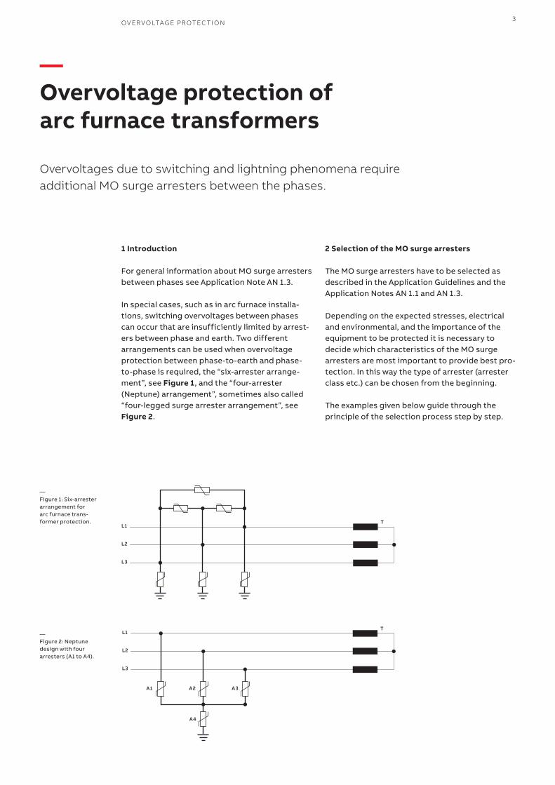
In special cases, such as in arc furnace installa-tions, switching overvoltages between phases can occur that are insufficiently limited by arrest-ers between phase and earth. Two different arrangements can be used when overvoltage protection between phase-to-earth and phase-to-phase is required, the “six-arrester arrange-ment”, see Figure 1, and the “four-arrester (Neptune) arrangement”, sometimes also called “four-legged surge arrester arrangement”, see Figure 2.
2 Selection of the MO surge arresters
The MO surge arresters have to be selected as described in the Application Guidelines and the Application Notes AN 1.1 and AN 1.3.
Depending on the expected stresses, electrical and environmental, and the importance of the equipment to be protected it is necessary to decide which characteristics of the MO surge arresters are most important to provide best pro-tection. In this way the type of arrester (arrester class etc.) can be chosen from the beginning.
The examples given below guide through the principle of the selection process step by step.
—Overvoltage protection of arc furnace transformers
Overvoltages due to switching and lightning phenomena require additional MO surge arresters between the phases.
Linienstärken für Grafiken
Linie oben: 1 pt, schwarz
Linie innen: 0.5 pt, grey03
Linie unten: 1 pt, grey03
Balkengrafiken:72 x 47 mm Aussenmass
Pfeil 7, 45 %
L1
L2
L3
T
Linienstärken für Grafiken
Linie oben: 1 pt, schwarz
Linie innen: 0.5 pt, grey03
Linie unten: 1 pt, grey03
Balkengrafiken:72 x 47 mm Aussenmass
Pfeil 7, 45 %
L1
L2
L3
T
A1 A2 A3
A4
—Figure 1: Six-arrester arrangement for arc furnace trans-former protection.
—Figure 2: Neptune design with four arresters (A1 to A4).
4 A PPLI C ATI O N N OTE A R C FU R N ACE TR A NSFO R M ER S
Supplied information• Protection of an arc furnace transformer• System voltage Us = 36 kV• High ohmic insulated star point• Industrial environment
Without further information it is assumed• Um = 36 kV• LIWV = 170 kV• Medium pollution (pollution class c, required
medium specific creepage 34.7 mm/kV)• Continuous operation in case of an earth fault• Nominal discharge current In = 10 kA• Short circuit current of the system Is = 20 kA
In such applications like protection of arc furnace transformers a high energy withstand capability has to be assumed, as well as a low protection level Upl of the MO surge arresters. For this reason a MO surge arrester of class SM (i.e. POLIM-S..N) is recommended.
The same procedure, equations and assumptions are valid for transformers in delta-connection.
2.1 Six-arrester arrangementFollowing the steps given in flow chart AN 1.1 A1, and the equations in AN 1.3, it follows:
Step a) Continuous operating voltage UcIn this case the continuous operating voltage is Uc ≥ 1.05 × Us = 1.05 × 36 kV = 37.8 kV
Therefore, chosen is according data sheet a POLIM-S .. N with Uc = 38 kV
As mentioned above, for such applications a low protection level is recommended. For this reason we don’t add a 10% safety margin for the Uc. This would increase the protection level Upl by 10% as well, which is not favorable in this application.
Step b) Rated voltage Ur According data sheet the rated voltage is Ur = 47.5 kV
Step c) Nominal discharge current InThe nominal discharge current is In = 10 kA
Step d) Charge Qrs and thermal rating WthBased on the decision for POLIM-S .. N (class SM) the • Repetitive charge transfer rating is Qrs = 2.0 C• Rated thermal energy is Wth = 10 kJ/kVUc
Step e) Check lightning impulse protection level Upl and withstand voltage LIWVRequired is: Upl ≤ LIWV / Ks
With LIWV = 170 kV and Ks = 1.15, the maximum allowed voltage at the electrical equipment results in 147.8 kV. The POLIM-S 38 N has an Upl of 114 kV and meets the demand with a good additional safety margin.
With the steps a) to e) the active part of the MO surge arrester is selected. It follows the selection of the arrester housing and confirmation of mechanical data.
Step f) Creepage distanceWith the assumption of medium pollution (pollu-tion class c with 34.7 mm/kV) we have to calculate the required creepage distance. As long as we as-sume continuous service in case of an earth fault we have to make the calculation based on 1.05 × Us. This results in a required minimum creepage distance of 1.05 × Us × 34.7 = 1312 mm. For insulation material like silicone the minimum required creepage distance can be reduced by 20%. This results finally in 1050 mm minimum creepage distance. The POLIM-S 38 N provides according data sheet a creepage distance of 1603 mm and meets the requirement with a good additional safety margin.
Step g) Flashover distanceThe minimum necessary withstand values of the empty arrester housing are calculated according to IEC 60099-4, Ed. 3.0 as:
Lightning voltage impulse 1.2/50 µs: 1.3 × Upl = 1.3 × 114 kV = 149 kV
a.c. voltage test 1 min, wet:1.06 × Ups
(switching current impulse 1000 A => Ups = 95.7 kV)It follows Utest,pv = 1.06 × 95.7 kV = 102 kV. This results in Utest =72 kV rms, 1 min wet.
The guaranteed withstand values according data sheet are:Lightning voltage impulse 1.2/50 µs: 359 kV a.c. voltage test: 102 kV, rms, 1min wet: 102 kV
The housing of the POLIM-S 38 N has higher withstand values than are required by IEC.
Step h) Short circuit current IsThe POLIM-S 38 N was tested with a short circuit current Is = 50 kA and meets easily the assumed 20 kA.
5
Step i) Mechanical loadsSpecial requirements for mechanical loads are not given. However, the type POLIM-S 38 N provides very good mechanical withstand values, see data sheet.
—It follows: the POLIM-S 38 N is the right arrester from all points of view for this application, and should be installed between the phases and the phases to earth.
2.2 Four-arrester arrangement (Neptune design)The same provided information and the assump-tions made apply for this example as well. We go with a MO surge arrester of type POLIM-S .. N.
2.2.1 Arrangement with four identical arresters
Step a) Continuous operating voltage UcAccording Figure 4 in AN 1.3 we calculate the con-tinuous operating voltage toUc ≥ 0.661 × Us = 0.661 × 36 kV = 23.8 kV
It follows from the data sheet with the next higher value a continuous operating voltage of Uc = 24 kV, and we go for a POLIM-S 24 N. We don’t add a safety margin of 10% to the Uc, because we have in the four arrester arrangement in all cases two arresters in series, which results in a total continuous operating voltage between the phases and phases to earth in Uc = 48 kV, which is far above the system voltage of Us = 36 kV.
Step b) Rated voltage Ur The rated voltage is according data sheet Ur = 30 kV
Step c) Nominal discharge current InThe nominal discharge current for this type of arrester (class SM) is In = 10 kA
Step d) Charge Qrs and thermal rating WthBased on the decision for POLIM-S .. N (class SM) the • Repetitive charge transfer rating is Qrs = 2.0 C• Rated thermal energy is Wth = 10 kJ/kVUc
Step e) we have to check the lightning impulse protection level Upl vs the withstand voltage LIWV.Required is Upl ≤ LIWV / Ks
The LIWV for the equipment to be protected re-mains the same. Therefore, we have to consider LIWV = 170 kV. As can be seen from the arrange-ment in Figure 4 in AN 1.3 we have to make the calculation with two POLIM-S 24 N in series.
This leads us to Upl ≤ LIWV / Ks = 170 kV / 1.15 = 148 kV.
The two POLIM-S 24 N in series have in total a Upl = 144 kV.
This value meets the requirement, but provides no additional safety margin.
Step f) Creepage distance Pollution effects and flashovers occur between the terminals of the MO surge arresters. For this reason, the creepage distance (as well as the flashover distance) has to be calculated for the single POLIM-S 24 N. We assume pollution class c with 34.7 mm/kV. In the actual case we have to calculate with the con-tinuous operating voltage Uc = 24 kV. This leads to a minimum recommended creepage distance of 24 kV x 34.7 mm/kV = 833 mm. With a 20% re-duction due to the silicone insulation we finally come to a value of 667 mm. The POLIM-S 24 N provides a creepage distance of 983 mm and ful-fills the requirement with a good margin.
Step g) Flashover distance The minimum necessary withstand values of the empty arrester housing are calculated according to IEC 60099-4, Ed. 3.0. Here again we concentrate on the single MO surge arrester POLIM-S 24 N, because the flash-over distance and related tests refer to the individual housing, independent of the final arrangement.
Lightning voltage impulse 1.2/50 µs:1.3 × Upl = 1.3 × 72 kV = 93.6 kV
a.c. voltage test 1 min, wet:1.06 × Ups
(Switching current impulse 1000 A => Ups = 60.5 kV)It follows Utest,pv = 1.06 × 60.5 kV = 64.13 kV. This results in Utest = 45.6 kV rms, 1 min wet.
The guaranteed withstand values according data sheet are:Lightning voltage impulse 1.2/50 µs: 239 kVa.c. voltage test 1 min, wet: 68 kV
The housings of the POLIM-S 24 N have higher withstand values than are required by IEC.
Step h) Short circuit current IsThe POLIM-S 24 N was tested with a short circuit current Is = 50 kA and meets easily the assumed 20 kA.
OV ER VO LTAG E PR OTEC TI O N
6 A PPLI C ATI O N N OTE A R C FU R N ACE TR A NSFO R M ER S
Step i) Mechanical loadsSpecial requirements for mechanical loads are not given. However, the type POLIM-S 24 N provides very good mechanical withstand values, see data sheet.
—It follows: the POLIM-S 24 N is the right arrester from all points of view for this application.
2.2.2 Arrangement with three identical MO arresters and one with lower UcThe same provided information and the assump-tions made apply for this example as well. We go with a MO surge arrester of type POLIM-S .. N.
Step a) Continuous operating voltage UcWith the equations under chapter 3.2 in AN 1.3 for a simp lified calculation of the continuous operating voltage we come to
1.05 × Us 1.05 × 36 kVUc ≥ UL-N = -------------- = ---------------- = 21.82 kV √3 1.732
The next higher value for the continuous operat-ing voltage is according data sheet Uc = 22 kV.
This leads us to a MO surge arrester POLIM-S 22 N for the MO surge arresters A1 to A3 between phases and neutral.
With the next higher value according data sheet we come to a POLIM-S 16 N for the MO surge ar-rester A4 between neutral and earth.
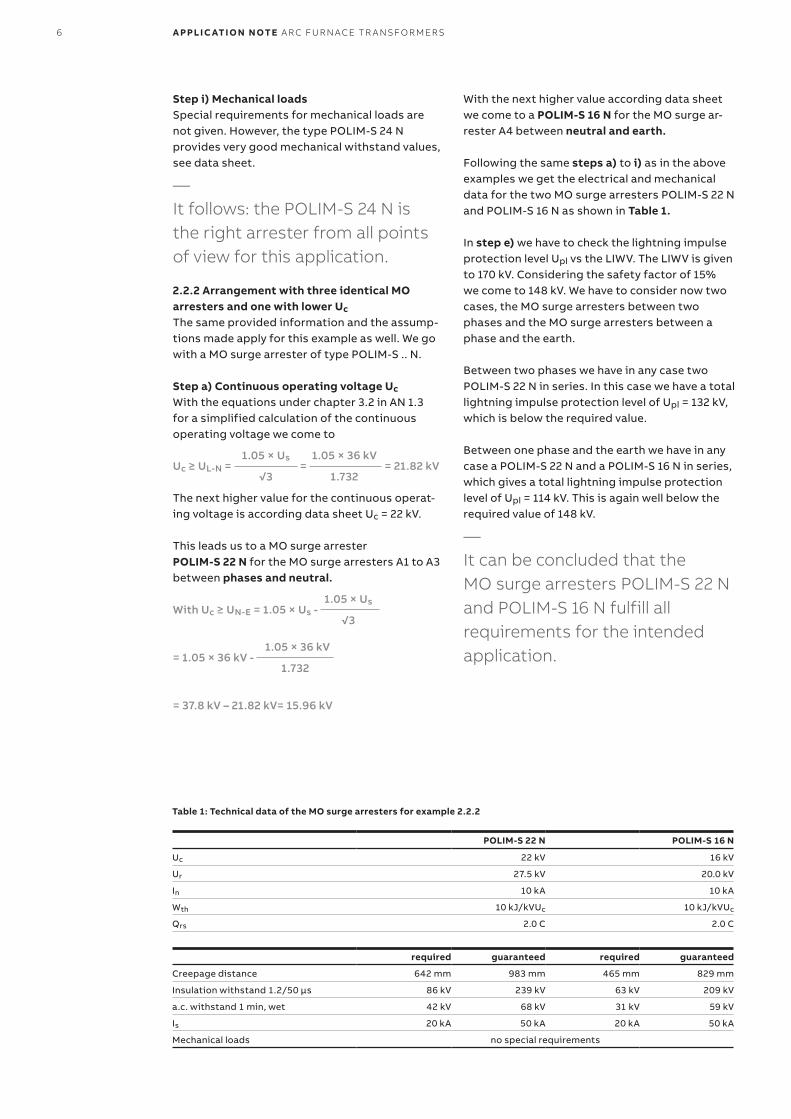
Following the same steps a) to i) as in the above examples we get the electrical and mechanical data for the two MO surge arresters POLIM-S 22 N and POLIM-S 16 N as shown in Table 1.
In step e) we have to check the lightning impulse protection level Upl vs the LIWV. The LIWV is given to 170 kV. Considering the safety factor of 15% we come to 148 kV. We have to consider now two cases, the MO surge arresters between two phases and the MO surge arresters between a phase and the earth.
Between two phases we have in any case two POLIM-S 22 N in series. In this case we have a total lightning impulse protection level of Upl = 132 kV, which is below the required value.
Between one phase and the earth we have in any case a POLIM-S 22 N and a POLIM-S 16 N in series, which gives a total lightning impulse protection level of Upl = 114 kV. This is again well below the required value of 148 kV.
—It can be concluded that the MO surge arresters POLIM-S 22 N and POLIM-S 16 N fulfill all requirements for the intended application.
Table 1: Technical data of the MO surge arresters for example 2.2.2
POLIM-S 22 N POLIM-S 16 N
Uc 22 kV 16 kV
Ur 27.5 kV 20.0 kV
In 10 kA 10 kA
Wth 10 kJ/kVUc 10 kJ/kVUc
Qrs 2.0 C 2.0 C
required guaranteed required guaranteed
Creepage distance 642 mm 983 mm 465 mm 829 mm
Insulation withstand 1.2/50 µs 86 kV 239 kV 63 kV 209 kV
a.c. withstand 1 min, wet 42 kV 68 kV 31 kV 59 kV
Is 20 kA 50 kA 20 kA 50 kA
Mechanical loads no special requirements
1.05 × UsWith Uc ≥ UN-E = 1.05 × Us - ------------- √3
1.05 × 36 kV= 1.05 × 36 kV - ----------------- 1.732
= 37.8 kV – 21.82 kV= 15.96 kV
OV ER VO LTAG E PR OTEC TI O N 7
3 Summary
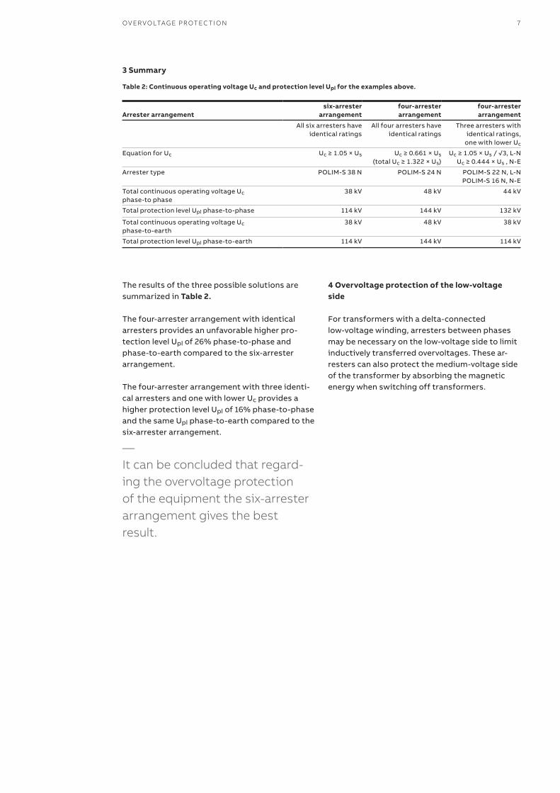
The results of the three possible solutions are summarized in Table 2.
The four-arrester arrangement with identical arresters provides an unfavorable higher pro-tection level Upl of 26% phase-to-phase and phase-to-earth compared to the six-arrester arrangement.
The four-arrester arrangement with three identi-cal arresters and one with lower Uc provides a higher protection level Upl of 16% phase-to-phase and the same Upl phase-to-earth compared to the six-arrester arrangement.
—It can be concluded that regard-ing the overvoltage protection of the equipment the six-arrester arrangement gives the best result.
4 Overvoltage protection of the low-voltage side
For transformers with a delta-connected low-voltage winding, arresters between phases may be necessary on the low-voltage side to limit inductively transferred overvoltages. These ar-resters can also protect the medium-voltage side of the transformer by absorbing the magnetic energy when switching off transformers.
Table 2: Continuous operating voltage Uc and protection level Upl for the examples above.
Arrester arrangementsix-arrester
arrangementfour-arrester arrangement
four-arrester arrangement
All six arresters have identical ratings
All four arresters have identical ratings
Three arresters with identical ratings,
one with lower Uc
Equation for Uc Uc ≥ 1.05 × Us Uc ≥ 0.661 × Us(total Uc ≥ 1.322 × Us)
Uc ≥ 1.05 × Us / √3, L-NUc ≥ 0.444 × Us , N-E
Arrester type POLIM-S 38 N POLIM-S 24 N POLIM-S 22 N, L-NPOLIM-S 16 N, N-E
Total continuous operating voltage Uc phase-to phase
38 kV 48 kV 44 kV
Total protection level Upl phase-to-phase 114 kV 144 kV 132 kV
Total continuous operating voltage Uc phase-to-earth
38 kV 48 kV 38 kV
Total protection level Upl phase-to-earth 114 kV 144 kV 114 kV
1HC
013
88
68
EN
AA
© Copyright 2019 ABB. All rights reservedSpecifications subject to change without notice
—ABB Switzerland Ltd.PGHVSurge ArrestersJurastrasse 45CH-5430 Wettingen/Switzerland Tel. + 41 58585 2911Fax + 41 58585 5570Email: [email protected]
abb.com/arrestersonline
Additional informationWe reserve the right to make technical changes or modify the content of this document without prior notice. With regard to purchase orders, the agreed particulars shall prevail. ABB AG does not accept any responsibility whatsoever for potential errors or possible lack of information in this document.
We reserve all rights in this document and in the subject matter and illustrations contained therein. Any reproduction, disclosure to third parties or utilization of its contents – in whole or in parts – is forbidden without prior written consent of ABB AG.