application engineering data - dynospindles · pdf fileapplication engineering data part two...
TRANSCRIPT


Application Engineering Data Part Two
1. Spindle Sizing 46 Power / Speed Requirements 46 2. Design Data Section 47 Cutting Speeds and feeds 47 Tbl 1. Recommended values for precision boring/turning 47 Tbl 2. Recommended values for precision milling 47 Tbl 3. Recommended values for drilling 47 Tbl 4. Recommended values for gun drilling – Carbide Tool 48 Estimating Machining Power 49 Tbl 5. Machining Power calculation: 49 Tbl 6. N- tool rotating speed calculation: 49 Tbl 7. Feed Factors, C, for Power Constants 50 Tbl 8. Tool Wear Factors W 51 Tbl 9. Power Constants for Ferrous Cast Metals -- Sharp Cutting Tools 51 Tbl 10. Power Constant for High-Temperature Alloys, Tool Steel Stainless 52 Steel and Nonferrous Metal, Using Sharp Cutting Tools 52 Tbl 11. Power Constants for Wrought Steels, Using Sharp Cutting Tools 53 Tbl 12. Formulas for Calculating the Metal Removal Rate, Q 54 DRILLING 55 Estimating Drilling Thrust, Torque, and Power 55 Tbl 13. Thrust, Torque and Power at Drilling with a Sharp Drill 55 Tbl 14. Work Material Factor for Drilling with a Sharp Drill 56 Tbl 15. Chisel Edge Factors for Torque and Thrust 56 Tbl 16. Feed Factors Ff for Drilling 57 Tbl 17. Drill Diameter Factors: FT for Thrust; FM for Torque 57 GRINDING 58 Grinding Forces, Torque and Power 58 Tbl 18. PG –Grinding Power 58 Tbl 19. Approximately KC can be taken in next ranges: 58 ECT – Equivalent chip thickness in Grinding 59 Tbl 20. ECT = equivalent chip thickness 59 Tbl 21. MRR = metal removal rate 60 Basic Rules 61 Tbl 22. Typical grinding parameter recommendations 61 Surface Finish– Ra 62 Side Feed, Roughing and Finishing 62 Tbl 23. C- fraction of grinding wheel width 62 Grinding Data Selection 63

Work materials 63 Tbl 24. Grindability Groups 63 Maximum wheel speeds 63 Tbl 25. Max. Peripheral Speeds for Grinding Wheels- ANSI B7.1-1988 64 Tbl 26. Formulas for calculating the rotational speed 65 3. The Driving Motor Characteristics 66 Driving Motor Power 66 Tbl 27. Driving Motor Power 66 Tbl 28. Machine Tool Efficiency Factors 66 Driving Motor Torque 66 Tbl 29. Formulas for calculating of Driving Motor Torque 66 Electrical source parameters 67 Tbl 30. Electrical Formulas 67 Tbl 31. Motor Amps at Full Load: 67 IEC Protection Indexes 68 IEC Cooling and Duty Cycle Indexes 69 4. Flowcharts 70 FLOWCHART FOR TURNING, BORING AND MILLING 70 FLOWCHART FOR DRILLING 71 FLOWCHART FOR GRINDING 72 5. Sizing Instructions 73 General rules for sizing 73 "DN" Value 74 Threads Rotation Guide 74 6. Most Common Spindle Nose Design 75 External Taper - G 75 Milling Taper per ANSI B5.18 – M 75 Milling Taper per ANSI B5.50 – MV 75 HSK per DIN 69893 - HA 76 HSK per DIN 69893 - HB 76 HSK per DIN 69893 - HC 76 Komet ABS®Connection - K 76 Other common available spindle nose designs 77 7. Conversion Constants and Formulas 78 Tbl 32. Length Conversion 78 Tbl 33. Weight Conversion 78 Tbl 34. Area Conversion 78 Tbl 35. Volume Conversion 78 Tbl 36. Force and Torque Conversion 79 Tbl 37. Power and Heat Conversion 79 Tbl 38. Pressure Conversion 79 Tbl 39. Temperature Conversion Table 80

Dynomax Information Part Three
1. Corporate Overview 82 2. Offering Overview 82 2.1 Design Offering 82 2.2 Manufacturing Offering 83 2.3 Service Offering 83 3. Request for Quote 84


- 46 -
1. SPINDLE SIZING Power / Speed Requirements
For proper spindle sizing, the machining power and speed requirements must be known or determined. The optimum spindle size for a specific application is depended on the operating speed of the spindle and the power that needs to be transmited by the spindle to accomplish the machining operation.
A major factor in selecting the proper spindle for a specific machining application is the amount of power required to do the work. This power requirement, is defined as the Unit Power. The Unit Power utilizes published machining data, based on the machining operation and recommended cutting speeds and feed rates as determined by the material and hardness of the workpiece, and geometry of the cutter.
After determining the recommended cutting speed and feed rate, the next step is to find the forces, torque and power, which will be present at the desired machining.
Information provided in the Design Data section, has been compiled to assist in applying the DYNOMAX high speed precision spindles to specific application requirements. This information is provided as a guide for a quick and simple means of approximating machining application requirements.
Consult a cutting tool specialist to obtain best results for final machining requirements. The Design Data section contains machining data tables and equations to calculate approximata power, speed and feed rates.
For grinding applications it is recommended that a grinding wheel manufacturer be conctacted to determine the proper safe operating speeds and power requirements to ensure that the grinding wheel is not operated above the maximum rated speeds.
The Flowchart section, provides an overview with step-by-step procedure to calculate the required spindle speed and power.
A short Spindle Sizing rules are given in the Sizing instruction section, to help with the selecting of the right spindle from DYNOMAX Spindle Catalogue.

- 47 -
2. DESIGN DATA SECTION Cutting Speeds and feeds
Table 1. Recommended values for precision boring/turning Hardness Cutting speed - High speed steel Cutting speed - Carbide uncoated Feed rate per revolution
Workpiece material [Bhn] Vc [feet/min] Vc [m/min] Vc [feet/min] Vc [m/min] f [inch] f [mm]
MIN MAX MIN MAX MIN MAX MIN MAX MIN MAX MIN MAX
Cast irons 190...320 16 197 5 60 33 492 10 150 0,003 0,020 0,080 0,500
Steel - plain carbon 85...200 49 394 15 120 197 919 60 280 0,003 0,020 0,080 0,500
Steel - alloys 35...50Rc 16 131 5 40 66 492 20 150 0,003 0,020 0,080 0,500
Steel - tool 50...58Rc 16 66 5 20 49 197 15 60 0,003 0,020 0,080 0,500
Steel - stainless 150...450 16 98 5 30 98 394 30 120 0,003 0,020 0,080 0,500
Aluminum alloys 30. . .150 492 1181 150 360 492 2625 150 800 0,003 0,020 0,080 0,500
Copper alloys 80...100Rb 98 591 30 180 164 1378 50 420 0,003 0,020 0,080 0,500
Nickel alloys 80. ..360 16 131 5 40 16 394 5 120 0,003 0,020 0,080 0,500
Titanium 250...375 16 98 5 30 33 328 10 100 0,003 0,020 0,080 0,500
Table 2. Recommended values for precision milling Hardness Cutting speed - High speed steel Cutting speed - Carbide uncoated Feed rate per tooth
Workpiece material [Bhn] Vc [feet/min] Vc [m/min] Vc [feet/min] Vc [m/min] ft [inch] ft [mm]
MIN MAX MIN MAX MIN MAX MIN MAX MIN MAX MIN MAX
Cast irons 190...320 16 197 5 60 33 492 10 150 0,005 0,012 0,120 0,300
Steel - plain carbon 85...200 49 394 15 120 197 919 60 280 0,005 0,012 0,120 0,300
Steel - alloys 35...50Rc 16 131 5 40 66 492 20 150 0,005 0,012 0,120 0,300
Steel - tool 50...58Rc 16 66 5 20 49 197 15 60 0,005 0,012 0,120 0,300
Steel - stainless 150...450 16 98 5 30 98 394 30 120 0,005 0,012 0,120 0,300
Aluminum alloys 30. . .150 492 1181 150 360 492 2625 150 800 0,005 0,012 0,120 0,300
Copper alloys 80...100Rb 98 591 30 180 164 1378 50 420 0,012 0,012 0,300 0,300
Nickel alloys 80...360 16 131 5 40 16 394 5 120 0,005 0,012 0,120 0,300
Titanium 250...375 16 98 5 30 33 328 10 100 0,005 0,012 0,120 0,300
Table 3. Recommended values for drilling Hardness Cutting speed Feed rate per revolution
Workpiece material [Bhn]
Cutting material Vc [feet/min] Vc [m/min] f [inch] f [mm]
MIN MAX MIN MAX MIN MAX MIN MAX
Cast irons 190...320 High speed steel 33 295 10 90 0,002 0,008 0,050 0,200
Steel - plain carbon 85. . .200 High speed steel 49 148 15 45 0,002 0,008 0,050 0,200
Steel - alloys 35...50Rc High speed steel 16 66 5 20 0,002 0,008 0,050 0,200
Steel - tool 50. . .58Rc High speed steel 16 66 5 20 0,002 0,008 0,050 0,200
Steel - stainless 150...450 High speed steel 16 33 5 10 0,002 0,008 0,050 0,200
Aluminum alloys 30. . . 150 High speed steel 16 377 5 115 0,002 0,008 0,050 0,200
Copper alloys 80...100Rb High speed steel 66 230 20 70 0,002 0,008 0,050 0,200
Nickel alloys 80...360 High speed steel 33 66 10 20 0,002 0,008 0,050 0,200
Titanium 250...375 High speed steel 16 49 5 15 0,002 0,008 0,050 0,200

- 48 -
Table 4. Recommended values for gun drilling – Carbide Tool
Gun Drill Diameters [inch]
Hardness Cutting speed 5/64" - 5/32" 5/32" - 1/4" 1/4" - 1/2" 1/2" - 3/4" 3/4" - 1" 1" - 2" Workpiece material [Bhn] Vc [feet/min] Vc [m/min] Feed - f [inch/revolution]
MIN MAX MIN MAX MIN MAX MIN MAX MIN MAX MIN MAX MIN MAX MIN MAXCast irons- soft 120-220 250 350 76 107 0,0003 0,001
Cast irons - hard 220-320 150 200 46 61 0,00015 0,00025
0,0003 0,00050,0015 0,001 0,003 0,002 0,005 0,003 0,007 0,003
Ductile Iron 140-260 200 300 61 91 0,00015 0,00025 0,0003 0,0005 0,0006 0,001 0,002 0,002
Malleable Iron 110-240 250 350 76 107 0,00015 0,00025 0,0003 0,0005 0,0006 0,001 0,002 0,002
Steel - soft 85...200 425 675 130 206
Steel - Medium 200-325 225 450 69 137
Steel - Hard 325-450 130 200 40 61
0,00015 0,00025 0,0003 0,0005 0,0006 0,001 0,001 0,002
Stainless Steel-Soft 135-275 250 300 76 91
Stainless Steel-Hard 275-425 150 225 46 69 0,00015 0,00025 0,0003 0,0005 0,0006 0,001 0,001 0,002
Aluminum alloys- except Die casting 650 198
Alum.Die casting 650 198
Magnesium 650 198
0,00015 0,00025 0,0003 0,001 0,003 0,005 0,008 0,01
Brass and Bronze 500 600 152 183 0,001 0,003 0,003 0,005 0,005 0,008 0,008 0,01
Copper 350 107 0,00015 0,00025 0,0003 0,0005
0,001 0,003 0,005 0,008
Gun Drill Diameters [inch]
Hardness Cutting speed 2,0 - 4,0 4,0 - 6,5 6,5 - 12,5 12,5 - 19,0 15,0 - 25,0 25,0 - 50,0 Workpiece material
[Bhn] Vc [feet/min] Vc [m/min] Feed - f [mm/revolution]
MIN MAX MIN MAX MIN MAX MIN MAX MIN MAX MIN MAX MIN MAX MIN MAXCast irons- soft 120-220 250 350 76 107 0,008 0,025
Cast irons - hard 220-320 150 200 46 61 0,0038 0,0064 0,008 0,013 0,038 0,025 0,076 0,051 0,127 0,064 0,178 0,076
Ductile Iron 140-260 200 300 61 91 0,0038 0,0064 0,008 0,013 0,015 0,02 0,038 0,051Malleable Iron 110-240 250 350 76 107 0,0038 0,0064 0,008 0,013 0,015 0,02 0,038 0,051
Steel - soft 85...200 425 675 130 206
Steel - Medium 200-325 225 450 69 137
Steel - Hard 325-450 130 200 40 61 0,0038 0,0064 0,008 0,013 0,015 0,02 0,025 0,038Stainless Steel - Soft 135-275 250 300 76 91
Stainless Steel - Hard 275-425 150 225 46 69 0,0038 0,0064 0,008 0,013 0,015 0,02 0,025 0,038Aluminum alloys-
except Die casting 650 198
Alum.Die casting 650 198
Magnesium 650 198 0,0038 0,0064 0,008 0,025 0,076 0,127 0,203 0,254Brass and Bronze 500 600 152 183 0,025 0,076 0,076 0,127 0,127 0,203 0,203 0,254
Copper 350 107 0,0038 0,0064 0,008 0,013 0,025 0,076 0,127 0,203

Estimating Machining Power
Knowledge of the power required to perform machining operations is useful when planning new machining operations, for optimizing existing machining operations, and finally to perform a properly Spindle sizing.
The available power on any machine tool Spindle, places a limit on the size of the cut that it can take. When much metal must be removed from the workpiece it is advisable to estimate the cutting conditions that will utilize the maximum power on the machine. Many machining operations require only light cuts to be taken for which the machine obviously has ample power; in this event estimating the power required is a wasteful effort. Conditions in different shops may vary and machine tools are not all designed alike, so some variations between the estimated results and those obtained on the job are to be expected.
However, by using the methods provided in this section a reasonable estimate of the power required can be made, which will suffice in most practical situations.
The measure of power in customary inch units is the horsepower; in SI metric units it is the kilowatt, which is used for both mechanical and electrical power The power required to cut a material depends upon the rate at which the material is being cut and upon an experimentally determined power constant Kp, which is also called the unit horsepower, unit power or specific power consumption. The power constant is equal to the horsepower required to cut a material at a rate of one cubic inch per minute; in SI metric units the power constant is equal to the power in kilowatts required to cut a material at a rate of one cubic centimeter per second, or 1000 cubic millimeters per second (1 cm3 = 1000 mm3). Different values of the power constant are required for inch and for metric units, which are related as follows: to obtain the SI metric power constant multiply the inch power constant by 2.73; to obtain the inch power constant divide the SI metric power constant by 2.73 .
Table 5. Machining Power calculation:
Pc [HP] = Kp[HP/ in.3/min]×C×Q[in.3/min]×W
Pc [kW] = Kp[kW/ cm3/s]×C×Q[cm3/s]×W
where: Pc = power at the cutting tool; HP, or kW Kp = power constant, HP/ in.3/min or kW/ cm3/s (Tables 9, 10 and 11) Q = metal removal rate; in.3/min. or cm3/s (Table 12) C = feed factor for power constant (Table 7) W = tool wear factor (Table 8) VC = cutting speed, fpm, or m/min (Table 1, 2, 3 and 4) N = tool rotating speed, rpm or min-1
f = feed rate for turning; in./rev. or mm/rev (Table 1) f = feed rate for planing and shaping; in./stroke, or mm/stroke ft = feed per tooth; in./tooth, or mm/tooth (Table 2) fm = feed rate; in./min. or mm/min dt = maximum depth of cut per tooth: in. or mm d = depth of cut; in. or mm nt = number of teeth on milling cutter D = Tool diameter in inch or mm
Table 6. N- tool rotating speed calculation:
Inch Units SI Metric Units
N- Tool rotating speed [rpm] [ ][ ].82.3inDfpmV
N C= [ ][ ]mmD
mVN C min/
47,318=
- 49 -

- 50 -
The value of the power constant is essentially unaffected by the cutting speed, the depth of cut and the cutting tool material. Factors that do affect the value of the power constant and thereby the power required to cut a material include the hardness and microstructure of the work material the feed rate, the rake angle of the cutting tool and whether the cutting edge of the tool is sharp or dull. Values are given in the power constant tables for different material hardness levels, whenever this information is available. Feed factors (C) for the power constant are given in Table 7. All metal cutting tools wear but a worn cutting edge requires more power to cut than a sharp cutting edge.
Factors to provide for tool wear are given in Table 8. In this table, the extra-heavy-duty category for milling and turning occurs only on operations where the tool is allowed to wear more than a normal amount before it is replaced, such as roll turning. The effect of the rake angle usually can be disregarded. The rake angle for which most of the data in the power constant tables are given is positive 14 degrees. Only when the deviation from this angle is large is it necessary to make an adjustment Using a rake angle that is more positive reduces the power required approximately 1 per cent per degree; using a rake angle that is more negative increases the power required; again approximately 1 per cent per degree.
Many indexable insert cutting tools are formed with an integral chip breaker or other cutting edge modifications, which have the effect of reducing the power required to cut a material The extent of this effect cannot be predicted without a test of each design. Cutting fluids will also usually reduce the power required, when operating in the lower range of cutting speeds. Again, the extent of this effect cannot be predicted because each cutting fluid exhibits its own characteristics.
Table 7. Feed Factors, C, for Power Constants Inch Unit SI Metric Unit
Feed
in.aC
Feed
in.aC
Feed
mm.bC
Feed
mm.bC
0.001 1.60 0.014 0.97 0.02 1.70 0.35 0.97
0.002 1.40 0.015 0.96 0.05 1.40 0.38 0.95 0.003 1.30 0.016 0.94 0.07 1.30 0.40 0.94 0.004 1.25 0.018 0.92 0.10 1.25 0.45 0.92 0.005 1.19 0.020 0.90 0.12 1.20 0.50 0.90 0.006 1.15 0.022 0.88 0.15 1.15 0.55 0.88 0.007 1.11 0.025 0.86 0.18 1.11 0.60 0.87 0.008 1.08 0.028 0.84 0.20 1.08 0.70 0.84 0.009 1.06 0.030 0.83 0.22 1.06 0.75 0.83 0.010 1.04 0.032 0.82 0.25 1.04 0.80 0.82 0.011 1.02 0.035 0.80 0.28 1.01 0.90 0.80 0.012 1.00 0.040 0.78 0.30 1.00 1.00 0.78 0.013 0.98 0.060 0.72 0.33 0.98 1.50 0.72
a Tuming-in/rev; milling-in./tooth; planing and shaping-in./stroke; broaching-in./tooth. b Tuming-mm/rev; milling-mm/tooth; planing and shaping-mm/stroke; broaching-mm/tooth.

- 51 -
Table 8. Tool Wear Factors W
Type of Operation W For all operations with sharp cutting tools: 1.00
Finish turning (light cuts) 1.10 Normal rough and semifinish turning 1.30 Turning Fxtra-heavy-duty rough turning 1.60 - 2.00 Slab milling 1.10 End milling 1.10 Milling Light and medium face milling 1.10 - 1.25 Extra-heavy-duty face milling 1.30 - 1.60 Normal drilling 1.30 Drilling Drilling hard-to-machine materials and drilling with a very dull drill
1.50
Normal broaching 1.05 - 1.10 Broaching Heavy-duty surface broaching 1.20 - 1.30
Note: For planing and shaping use values given for turning.
Power Constants Kp
Values of the power constant in Tables 9, 10, and 11 can be used for all machining operations except drilling and grinding. Values given are for sharp tools.
Table 9. Power Constants Kp for Ferrous Cast Metals Using Sharp Cutting Tools
Material Brinell
Hardness Number
Kp
Inch Unit
Kp
SI Metric Unit
Material Brinell
Hardness Number
Kp
Inch Unit
Kp
SI Metric Unit
110-120 0.28 0.76 Malleable Iron 120-140 0.35 0.96 150-175 0.42 1.15 140-160 0.38 1.04
Ferritic 175-200 0.57 1.56
160-180 0.32 1.42 200-250 0.82 2.24 180-200 0.60 1.64
Pearlitic 250-300 1.18 3.22
200-220 0.71 1.94
Gray Cast Iron
220-240 0.91 2.48 150-175 0.62 1.69 150-175 0.30 0.82 175-200 0.78 2.13 175-200 0.63 1.72
Cast Steel 200-250 0.86 2.35
Alloy Cast Iron
200-250 0.92 2.51

- 52 -
Table 10. Power Constant, KP, for High-Temperature Alloys, Tool Steel Stainless
Steel and Nonferrous Metal, Using Sharp Cutting Tools
Material Brinell Hardness Number
KP
Inch Units
KP
Metric Units
Material Brinell Hardness Number
KP
Inch Units
KP
Metric Units
High-Temp. Alloys 150-175 0.60 1.64 A 286 165 0.82 2.24 175-200 0.72 1.97 A 286 285 0.93 2.54
Stainless Steel 200-250 0.88 2.40
Chromology 200 0.87 3.22
Zinc Die Cast Alloys
… 0.25 0.68
Chromology 310 1.18 3.00 Pure Copper … 0.91 2.48 Inco 700 330 1.12 3.06 Inco 702 230 1.10 3.00 … 0.83 2.27 Hastelloy-B 230 1.10 3.00 … 0.50 1.36 M-252 230 1.10 3.00 … 0.25 0.68 M-252 310 1.20 3.28
Brass: Hard Medium Soft Leaded … 0.30 0.82
Ti-150 A 340 0.65 1.77 U-500 375 1.10 3.00 … 0.91 2.48 Monel Metal … 1.00 2.73
Bronze: Hard Medium … 0.50 1.36
175-200 0.75 2.05 200-250 0.88 2.40 … 0.25 0.68 250-300 0.98 2.68
Aluminum: Cast Rolled (Hard) … 0.33 0.90
300-350 1.20 3.28 Tool Steel
350-400 1.30 3.55 Magnesium Alloys
… 0.10 0.27

- 53 -
Table 11. Power Canstants, Kp for Wrought Steels, Using Sharp Cutting Tools
Material
Brinell Hardness Number
Kp
Inch Units
Kp
SI Metric Units
Plain Carbon Steels All Plain Carbon Steels
80-100 100-120 120-140 140-160 160-180 180-200 200-220 220-240 240-260 260-280 280-300 300-320 320-340 340-360
0.63 0.66 0.69 0.74 0.78 0.82 0.85 0.89 0.92 0.95 1.00 1.03 1.06 1.14
1.72 1.80 1.88 2.02 2.13 2.24 2.32 2.43 2.51 2.59 2.73 2.81 2.89 3.11
Free Machining Steels AISI 1108, 1109, 1110, 1115, 1116, 1117,1118,1119, 1120, 1125, 1126, 1132
100-120 120-140 140-160 160-180 180-200
0.41 0.42 0.44 0.48 0.50
1.12 1.15 1.20 1.31 1.36
AISI 1137, 1138, 1139, 1140, 1141, 1144, 1145, 1146, 1148, 1151
180-200 200-220 220-240 240-260
0.51 0.55 0.57 0.62
1.39 1.50 1.56 1.69
Alloy Steels AISI 4023, 4024, 4027, 4028, 4032 4037, 4042, 4047, 4137, 4140, 4142 4145, 4147, 4150, 4340, 4640, 4815, 4817, 4820, 5130 5132 5135, 5140 5145, 5150, 6118, 6150, 8637, 8640, 8642, 8645, 8650, 8740
140-160 160-180 180-200 200-220 220-240 240-260 260-280 280-300 300-320 320-340 340-360
0.62 0.65 0.69 0.72 0.76 0.80 0.84 0.87 0.91 0.96 1.00
1.69 1.77 1.88 1.97 2.07 2.18 2.29 2.38 2.48 2.62 2.73
AISI 4130, 4320, 4615, 4620, 4626, 5120, 8615, 8617, 8620, 8622, 8625, 8630, 8720
140-160 160-180 180-200 200-220 220-240 240-260 260-280 280-300 300-320 320-340
0.56 0.59 0.62 0.65 0.70 0.74 0.77 0.80 0.83 0.89
1.53 1.61 1.69 1.77 1.91 2.02 2.10 2.18 2.27 2.43
AISI 1330, I335, 1340, E52100 160-180 180-200 200-220 220-240 240-260 260-280
0.79 0.83 0.87 0.91 0.95 1.00
2.16 2.27 2.38 2.48 2.59 2.73

- 54 -
Formulas for calculating the metal removal rate, Q, for different machining operations are given in Table 12. These formulas are used together with others given below. The following formulas can be used with either customary inch or with SI metric units.
Table 12. Formulas for Calculating the Metal Removal Rate, Q
Metal Removal Rate Operation For Inch Units Only
Q = in.P
3P/min
For SI Metric Units Only Q = cmP
3P/s
Single-Point Tools (Turning, planing, and Shaping)
12 VBCB f d UVUBUCUBU f d
60
Milling f BmB w d Uf UBUmUBU w dU
60,000
Surface Broaching 12 VBCB w nBcB dBt B
UVUBUCUBU w nUBUcUBU dUBUt UB
60 nBc B= number of teeth engaged in work w = width of cut; in. or mm VBCB = cutting speed, fpm, or m/min (see Table 1, 2, 3 and 4) f = feed rate for turning; in./rev. or mm/rev (see Table 1) f = feed rate for planing and shaping; in./stroke, or mm/stroke fBmB = feed rate; in./min. or mm/min d BtB = maximum depth of cut per tooth: in. or mm d = depth of cut; in. or mm Whenever possible the maximum power available on a machine tool should be use when heavy cuts must be taken. The cutting conditions for utilizing the maximum power should be selected in the following order: 1) select the maximum depth of cut that can be used; 2) select the maximum feed rate that can be used; 3) estimate the cutting speed that will utilize the maximum power available on the machine. This sequence is based on obtaining the longest tool life of the cutting tool and at the same time obtaining as much production as possible from the machine. The life of a cutting tool is most affected by the cutting speed then by the feed rate, and least of all by the depth of cut. The maximum metal removal rate that a given machine is capable of machining from a given material is used as the basis for estimating the cutting speed that will utilize all the power available on the machine.

- 55 -
DRILLING Estimating Drilling Thrust, Torque, and Power Although the lips of a drill cut metal and produce a chip in the same manner as the cutting edges of other metal cutting tools, the chisel edge removes the metal by means of a very complex combination of extrusion and cutting. For this reason a separate method must be used to estimate the power required for drilling. Also, it is often desirable to know the magnitude of the thrust and the torque required to drill a hole. The formulas and tabular data provided in this section are based on information supplied by the National Twist Drill Division of Regal-Beloit Corp. The values in Tables 13 through 16 are for sharp drills and the tool wear factors are given in Table 8. For most ordinary drilling operations 1.30 can be used as the tool wear factor. When drilling most difficult-to-machine materials and when the drill is allowed to become very dull, 1.50 should be used as the value of this factor. It is usually more convenient to measure the web thickness at the drill point than the length of the chisel edge; for this reason, the approximate w/d ratio corresponding to each c/d ratio for a correctly ground drip is provided in Table 14. For most standard twist drills the c/d ratio is 0.18, unless the drill has been ground short or the web has been thinned. The c/d ratio of split point drills is 0.03. The formulas given below can be used for spade drills as well as for twist drills. Separate formules are required for use with customary inch units and for SI metric units:
Table 13. Thrust, Torque and Power at Drilling with a Sharp Drill Inch Units SI Metric Units Thrust T = 2 KBd BFBfB FBT B BW+ KBdB dP
2P J W [lb] T= 0.05 KBdB FBfB FBT B B W + 0.007 KBdB dP
2P J W [N]
Torque M= KBdB FBfB FBM BA W [in.-lb] M= 0.000025 KBdB FBfB FBM BA W [Nm] Power at the cutter
P BcB = M N / 63.025 [HP] PBcB = M N / 9550 [kW]
where:
P BcB = Power at the cutter; hp, or kW M = Torque; in.- Ib, or Nm T = Thrust; Ib, or N K Bd B = Work material factor (See Table 14) FBfB = Feed factor (See Table 16) FBT B = Thrust factor for drill diameter (See Table 17) FBMB = Torque factor for drill diameter (See Table 17) A = Chisel edge factor for torque (See Table 15) B = Chisel edge factor for thrust (See Table 15) J = Chisel edge factor for thrust (See Table 15) W = Tool wear factor (See Table 8) N = Spindle speed; rpm D = Drill diameter; in, or mm c = Chisel edge length; in, or mm (See Table 15) w = Web thickness at drill point; in, or mm (See Table 15)

- 56 -
Table 14. Work Material Factor, KBd B for Drilling with a Sharp Drill
Work Material
Constant KBd B
AISI 1117 (Resulfurized free machining mild steel) 12,000 Steel, 200 Bhn 24,000 Steel, 300 Bhn 31,000 Steel, 400 Bhn 34,000 cast Iron, 150 Bhn 14,000 Most Aluminum Alloys 7,000 Most Magnedum Alloys 4,000 Most Brasses 14,000 Leaded Brass 7,000
24,000P
aP for Torque
Austenitic Stainless Steel (Type 316) 35,000P
aP for Thrust
18000P
aP for Torque
Titanium Alloy T16A 29,000P
aP for Thrust
Rent 41 40,000P
abP min.
30,000P
aP for Torque
Hastelloy-c 37,000P
aP for Thrust
P
aPValues based upon a limited number of tests.
P
bPWill increase with rapid wear
Table 15. Chisel Edge Factors for Torque and Thrust
c/d Approx.
w/d
Torque Factor
A
Thrust Factor
B
Thrust Factor
J c/d
Approx. w/d
Torque Factor
A
Thrust Factor
B
Thrust Factor
J 0.03 0.025 1.000 1.100 0.001 0.18 0.155 1.085 1.355 0.030 0.05 0.045 1.005 1.140 0.003 0.20 0.175 1.105 1.380 0.040 0.08 0.070 1.015 1.200 0.006 0.25 0.220 1.155 1.445 0.065 0.10 0.085 1.020 1.235 0.010 0.30 0.260 1.235 1.500 0.090 0.13 0.110 1.040 1.270 0.017 0.35 0.300 1.310 1.575 0.120 0.15 0.130 1.080 1.310 0.022 0.40 0.350 1.395 1.620 0.160
Note: For drills of standard design, use c/d = 0.18 For split point drills, use c/d= 0.03 c/d = Length of Chisel Edge / Drill Diameter w/d= Web Thickness at Drill Point / Drill Diameter
- 57 -
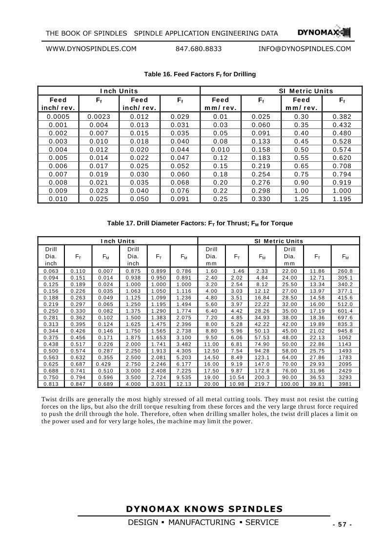
Table 16. Feed Factors FBf B for Drilling
Inch Units SI Metric Units Feed
inch/rev. FBf B Feed
inch/rev. FBf B Feed
mm/rev. FBf B Feed
mm/rev. FBf B
0.0005 0.0023 0.012 0.029 0.01 0.025 0.30 0.382 0.001 0.004 0.013 0.031 0.03 0.060 0.35 0.432 0.002 0.007 0.015 0.035 0.05 0.091 0.40 0.480 0.003 0.010 0.018 0.040 0.08 0.133 0.45 0.528 0.004 0.012 0.020 0.044 0.010 0.158 0.50 0.574 0.005 0.014 0.022 0.047 0.12 0.183 0.55 0.620 0.006 0.017 0.025 0.052 0.15 0.219 0.65 0.708 0.007 0.019 0.030 0.060 0.18 0.254 0.75 0.794 0.008 0.021 0.035 0.068 0.20 0.276 0.90 0.919 0.009 0.023 0.040 0.076 0.22 0.298 1.00 1.000 0.010 0.025 0.050 0.091 0.25 0.330 1.25 1.195
Table 17. Drill Diameter Factors: F BT B for Thrust; FBM B for Torque
Inch Units SI Metric Units Drill Dia. inch
FBT B FBMB
Drill Dia. inch
FBT B FBMB
Drill Dia. mm
FBT B FBMB
Drill Dia. mm
FBT B FBMB
0.063 0.110 0.007 0.875 0.899 0.786 1.60 1.46 2.33 22.00 11.86 260.8 0.094 0.151 0.014 0.938 0.950 0.891 2.40 2.02 4.84 24.00 12.71 305.1 0.125 0.189 0.024 1.000 1.000 1.000 3.20 2.54 8.12 25.50 13.34 340.2 0.156 0.226 0.035 1.063 1.050 1.116 4.00 3.03 12.12 27.00 13.97 377.1 0.188 0.263 0.049 1.125 1.099 1.236 4.80 3.51 16.84 28.50 14.58 415.6 0.219 0.297 0.065 1.250 1.195 1.494 5.60 3.97 22.22 32.00 16.00 512.0 0.250 0.330 0.082 1.375 1.290 1.774 6.40 4.42 28.26 35.00 17.19 601.4 0.281 0.362 0.102 1.500 1.383 2.075 7.20 4.85 34.93 38.00 18.36 697.6 0.313 0.395 0.124 1.625 1.475 2.396 8.00 5.28 42.22 42.00 19.89 835.3 0.344 0.426 0.146 1.750 1.565 2.738 8.80 5.96 50.13 45.00 21.02 945.8 0.375 0.456 0.171 1.875 1.653 3.100 9.50 6.06 57.53 48.00 22.13 1062 0.438 0.517 0.226 2.000 1.741 3.482 11.00 6.81 74.90 50.00 22.86 1143 0.500 0.574 0.287 2.250 1.913 4.305 12.50 7.54 94.28 58.00 25.75 1493 0.563 0.632 0.355 2.500 2.081 5.203 14.50 8.49 123.1 64.00 27.86 1783 0.625 0.687 0.429 2.750 2.246 6.177 16.00 9.19 147.0 70.00 29.93 2095 0.688 0.741 0.510 3.000 2.408 7.225 17.50 9.87 172.8 76.00 31.96 2429 0.750 0.794 0.596 3.500 2.724 9.535 19.00 10.54 200.3 90.00 36.53 3293 0.813 0.847 0.689 4.000 3.031 12.13 20.00 10.98 219.7 100.00 39.81 3981
Twist drills are generally the most highly stressed of all metal cutting tools. They must not resist the cutting forces on the lips, but also the drill torque resulting from these forces and the very large thrust force required to push the drill through the hole. Therefore, often when drilling smaller holes, the twist drill places a limit on the power used and for very large holes, the machine may limit the power.

- 58 -
GRINDING Grinding Forces, Torque and Power
Formulas to calculate the tangential cutting force, torque and required machining power are the same as for other metal cutting operations (see Estimating Machining Power Section), but the values of KBCB , specific cutting force or specific energy, are approximately 30 to 40 times higher in grinding than in turning, milling and drilling. This is primarily due to the fact that the ECT values in grinding are 1000 to 10000 times smalles, and also due to the negative rake angles of the grit. Average grinding rake angles are arround –35 to –45 degrees.
Another difference compared to turning is the influence of the negative rake angles, illustrated by the ratio of FBHB/FBCB, where FBHB is the normal force and F BCB the tangential grinding force acting in the wheel speed direction. F BHB is much larger than the grinding cutting force.
Generally FBH B/FBCB ratio is approximately 2 to 4.
It is apparent that both KBCB and FBH B/FBCB attain maximum values for given small values of ECT. This fact illustrates that forces and wheel-life are closely linked. For example, wheel speed has a maximum for constant wheel-life at appoximately the same values of ECT. As a matter of fact, force relationships obey the same type of relationships as those of wheel-life.
The informations compiled in this section is intended as a guide in selecting the proper parameters for a particular grinding operation. The process of selecting the proper power, speed feed wheel etc., should be based on experience and testing. There are no general equation that can adequately describe the selection process without use of test results for the particular application.
Grinding Power
The relationship for the Grinding power calculation can be expressed as:
PBGB = KBCB x MRR [HP] or [kW]
Table 18. PBGB –Grinding Power Inch Units SI Metric Units
Grinding Power 270,396
MRRKP C
G⋅
= [HP] 000,000,60
MRRKP C
G⋅
= [kW]
where :
P BGB = Grinding power at the grinding wheel; HP, or kW K BCB = specific cutting force [psi] or [N/mm P
2P] – see Table 19.
MRR = metal removal rate [mm P
3P/min] or [inP
3P/min] – see Table 21.
Table 19. Approximately KBC B can be taken in next ranges:
Material KBCB [N/mmP
2P] KBCB [psi]
unhardened steel 50,000 to 70,000 N/mmP
2P 7,250,000 to 10,150,000
hardened steel 150,000 to 200,000 N/mmP
2P 21,750,000 to 29,000,000
The grinding cutting forces are relatively small because chip area is very small.

- 59 -
As in the other metal cutting operations, the forces vary with ECT - equivalent chip thickness and to a smaller extent with the weel speed V.
ECT – Equivalent chip thickness in Grinding
The definition of ECT is: CEL
AECT = [mm] or [inch]
where: A- cross sectional area of cut (approximately = feed x depth of cut) – [mm P
2P] or [inchP
2P]
CEL – cutting edge length (tool contact rubbing length) – [mm] or [inch]
In turning, milling and drilling, ECT varies between 0.05 and 1 mm, and is always less than the feed/rev or feed/tooth; its value is usually about 0.7 to 0.9 times the feed.
ECT is much smaller in grinding than in milling, ranging from about 0.0001 to 0.001 mm (0.000004 to 0.00004 inch).
In turning and milling, ECT is defined as the volume of chips removed per unit cutting edge length per revolution of the work or cutter. In milling specifically, ECT is defined as the ratio of (number of teeth z x feed per tooth f, x radial depth of cut aBrB x axial depth of cut aBaB) and (cutting edge length CEL divided by πD) where D is the cutter diameter, thus,
CEL
aafzDECT arz ⋅⋅⋅⋅⋅
=π
In grinding, the same definition of ECT applies if we replace the number of teeth with the average number of grits along the wheel periphery, and replace the feed per tooth by the average feed per grit. This definition is not very practical, however, and ECT is better defined by the ratio of the specific metal removal rate - SMMR, and the wheel speed - V. Keeping ECT constant when varying SMRR requires that the wheel speed must be changed proportionally.
In milling and turning ECT can also be redefined in terms of SMRR divided by the work and the cutter speeds respectively, because SMRR is proportional to the feed rate F BR B.
ECT = equivalent chip thickness =f(aBrB,V,VBWB,fBS B) [mm] or [inch]
( )V
aelyapproximatVafV
ECT rrSW ⋅=
+= wV
1
Table 20. ECT = equivalent chip thickness
Inch Units SI Metric Units
ECT 12⋅
⋅=
VfSMRR
ECT S [inch] 1000⋅⋅
=V
fSMRRECT S [mm]

- 60 -
Table 21. MRR = metal removal rate MRR = SMRR x f BS B MRR = (1000 x aBrB x VBWB) x fBS B [mm P
3P/min] or [inP
3P/min]
Inch Units SI Metric Units
MRR
12⋅⋅= VECTMRR [inP
3P/min] 1000⋅⋅= VECTMRR [mmP
3P/min]
Terms and Definitions: aBaB = width of cut [mm] or [inch] aBrB = radial depth of cut [mm] or [inch] C = fraction of grinding wheel width CEL = cutting edge length, [mm] or [inch] D = wheel diameter, [mm] or [inch] DIST = grinding distance, [mm] or [inch] d BWB = work diameter [mm] or [inch] FBR B = feed rate, [mm/min] or [inch/min] =fBS B x RPM, for cylindrical grinding =fBi B x RPM, for plunge (in-feed) grinding f Bi B = in-feed in plunge grinding [mm/rev of work] fBS B = side feed or engaged wheel width in cylindrical grinding [mm] or [inch] fBS B = C x Width = a BaB approximately equal to the cutting edge length - CEL SMRR = specific metal removal rate obtained by dividing MRR by the engaged wheel width fBS
SMRR = 1000 x a BrB x VBWB [mm3/mm width/min] 100 [mmP
3P/mm/min] = 0.155 [inP
3P/in/min]
1 [in P
3P/in/min] = 645.16 [mmP
3P/mm/min]
Width = wheel width [mm] Grindingratio = MRR/W* = SMRR x T / W* = 1000 x ECT x V x T /W* T, TBU B =wheel-life = Grinding ratio x W/(1000 x ECTx V) [minutes] W P
*P =volume wheel wear [mmP
3P]
t BCB = grinding time per pass = DIST/F BR B [min] = DIST/F BR B + t BSP B[min] - when spark-out time is included = # Strokes x (DIST/FBR B + t BSP B) [min] when spark-out time and strokes are included t BSPB = spark-out time, [minutes] V,VBU B = wheel speed, [m/min] or [feet/min] VBW,BVBWU B = work speed = SMRR / (1000 x a BrB) [m/min] or [feet/min] W* = volume wheel wear [mm P
3P]
Width = wheel width [mm] RPM = wheel speed = (1000 x V)/(D x π) [rpm] – for SI Metric Unit
RPMBWB = work speed = (1000 x V BWB)/(DBWB x π) [rpm] – for SI Metric Unit

- 61 -
Basic Rules
Grinding data are scarely available in handbooks, which usually recommend a small range of depth and work speeds at constant wheel speed, including small variations in wheel and work material composition. Wheel life or grinding stiffness are seldom considered.
Table 22. Grinding parameter recommendations typically range as follows: Recommended grinding
parameter SI- Metric Units Inch Units
Wheel speed 1200 to 1800 m/min 4000 to 6000 fpm Work speed 20 to 40 m/min 70 to 140 fpm Depth of cut for roughing grinding 0.01 to 0.025 mm 0.0004 to 0.001 inch Depth of cut for finish grinding around 0.005 mm around 0.0002 inch Grit sizes for roughing grinding for easy-to-grind materials
46 to 60
Grit sizes for roughing grinding for difficult-to-grind materials
> 80
Internal griding grit sizes for small holes
100 to 320
Specific metal removal rate – SMRR P
*P
200 to 500 mmP
3P/mm width/min
0.3 to 0.75 in P
3P/inch width/min
P
*PSpecific metal removal rate – SMRR, represents the rate of material removal per unit of wheel contact width
- Grinding stiffness is a major variable in determining wheel-life and spark out time. A typical value of system stiffness in outside-diameter grinding, for 10:1 length/diameter ratio, is approximately KBST B = 30 – 50 N/μm. System stiffness KBST B is calculated from the stiffness of the part – KBW B and the machine fixtures KBm B. Machine values can be obtained from manufacturers, or can be measured using simple equipment along with the part stiffness.
- Generally a lower wheel hardness (soft wheel) is recommended when the system stiffness is poor or when a better finish is desired.
The primary parameters that determine wheel-life, forces and surface finish in grinding are: - the wheel speed V
- equivalent chip thickness ECT
The following general rules and recommendations, using ECT, are based on extensive laboratory and industry tests both in Europe and USA. The relationships and shapes of curves pertaining to grinding tool-life, grinding time, and cost are similar to those of any metal cutting operation such as turning, milling and drilling. In turning and milling, the ECT theory says that if the product of feed times depth of cut is constant, the tool-life is constant no matter how the depth of cut or feed is varied, provided that the cutting speed and cutting edge length are maintained constant.
In grinding, wheel-life T remains constant for constant cutting speed V, regardless of how depth of cut a BrB or work speed V, are selected as long as the specific metal removal rate
SMMR = VBw B x aBrB is held constant (neglecting the influence of grinding contact width).

- 62 -
Surface Finish– RBaB
In cylindrical grinding, a reduction of side feed fBS B improves RBaB, as well. Small grit sizes are very important when very small finishes are required.
The finish is improved by decreasing the value of ECT. Because ECT is proportional to the depth of cut, a smaller depth of cut is favorable for reducing surface roughness when the work speed is constant.
Shorter wheel-life improves the surface finish, which means that either an increased wheel speed (wheel-life decreases) at constant ECT, or a smaller ECT at constant speed (wheel-life increases), will result in an improved finish. For a required surface finish, ECT and wheel-life have to be selected appropriately in order to also achieve an optimum grinding time or cost. In cylindrical grinding a reduction of side feed f Bs B, improves Ra as well.
In terms of specific metal removal rate, reducing SMRR will improve the surface finish RBaB.
Side Feed, Roughing and Finishing
In cylindrical grinding, the side feed: f Bs B = C x Width
does impact on the feed rate FBR B, where the fraction of the wheel width C is usually selected for roughing and in finishing operations, as shown in the following table
Table 23. C- fraction of grinding wheel width
Work Material Roughing, C Finishing, C Steel 2/3 – 3/4 1/3 – 3/8 Stainless Steel 1/2 1/4 Cast Iron 3/4 3/8 Hardened Steel 1/2 1/4
The depth of cut in rough grinding is determined by the allowance and usually set at aBrB = 0.01 to 0.025 mm (0.254 to0.635 inch).
The depth of cut for finishing is usually set at aBrB = 0.0025 mm (0.0635 inch) and accompanied by higher wheel speeds in order to improve surface finish. However the most important criterion for critical parts is to increase the work speed in order to avoid thermal damage and surface cracks.

- 63 -
Grinding Data Selection Work materials
The first estimate settings is based on dividing work materials into 10 groups, based on grindability, as given in next
Table 24. Grindability Groups Group Examples
Group 1 Unhardened Steels Group 2 Stainless SteelUsU SAE 30201-30347, 51409-51501 Group 3 Cast iron Group 4 Tool Steels M1, M8, T1, H, O, L, F 52100 Group 5 Tool Steels M2, T2, T5, T6, D2, H41, H42, H43, M50 Group 6 Tool Steels M3, M4, T3, D7 Group 7 Tool Steels T15, M15 Group 8 Heat Resistaut Steels Inconel, Rene etc. Group 9 Carbide Materials P30 Diamond Wheel Group 10 Ceramic MaterialUsU
The grinding data machinability system is based on the basic parameters equivalent chip thickness ECT, and wheel speed V, and is used to determine specific metal removal rates SMRR and wheel-life T, including the work speed V BWB, after the grinding depths for roughing and finishing are specified.
Maximum wheel speeds
The maximum peripheral speed of the wheels in regular High-Speed Cylindrical Grinding is generally 6500 feet per minute; the commonly used grinding wheels and machines are designed to operate efficiently at this speed.
Recently, efforts were made to raise the productivity of different grinding metbods, including cylindrical grinding, by increasing the peripheral speed of the grinding wheel to a substantially higher than traditional level such as 12,000 feet per minute or more. Such methods are designated by the distinguishing term of high-speed grinding.
For high-speed grinding, special grinding machines have been built with high dynamic stiffness and static rigidity, equipped with powerful drive motors, extra-strong spindles and bearings, reinforced wheel guards, etc, and using grinding wheel expressly made and tested for operating at high peripheral speeds. The higher stock-removal rate accomplished by high-speed grinding represents an advantage when the work configuration and material permit and the removable stock alowance warrants its application.
The general design of the grinding machines must ensure safe operation under normal conditions. The bearings and grinding wheel spindle must be dimensioned to withstand the expected forces and ample driving power should be provided to ensure maintenance of the rated spindle speed.

- 64 -
The Table 25. shows the permissible wheel speeds in surface feet per minute (sfpm) units and [m/min], whereas the tags on the grinding wheels state, for the convenience of the user, the maximum operating speed in revolutions per minute (rpm).
Table 25. Max. Peripheral Speeds for Grinding Wheels- Based on ANSI B7.1-1988 Maximum Operating Surface Speeds
sfpm –feet per minute (m/min)
Depending on Streingth of Bond
Classification No. Types of WheelsP
aP
Inorganic Bonds Organic Bonds
1
Straight wheels - Type 1, except classsifications 6, 7, 9, 10, 11, and 12 below Type 4P
bP - Taper Side Wheels
Types 5, 7, 20, 21, 22, 23, 24, 25, 26 Dish wheels - Type 12 Saucer wheels - Type 13 Cones and plugs - Types 16, 17, 18, 19
5,500 to 6,500 (1674 to 1980)
6,500 to 9,500 (1980 to 2898)
2 Cylinder wheels - Type 2 Segments
5,000 to 6,000 (1524 to 1830)
5,000 to 7,000 (1524 to 2136)
3 Cup shape tool grinding wheels – Types 6 and 11 (for fixed base machines)
4,500 to 6,000 (1374 to 1830)
6,000 to 8,500 (1830 to 2592)
4 Cup shape snagging wheels - Types 6 and 11 (for portable machines)
4,500 to 6,500 (1374 to 1980)
6,000 to 9,500 (1830 to 2898)
5 Abrasive disks 5,500 to 6,500 (1674 to 1980)
5,500 to 8,500 (1674 to 2592)
6 Reinforced wheels - except cutting-off wheels (depending on diameter and thickness)
… 9,500 to 16,000 (2898 to 4878)
7 Type 1 wheels for bench and pedestal grinders, Types 1 and 5 also in certain sizes for surface grinders
5,500 to 7,550 (1674 to 2304)
6,500 to 9,500 (1980 to 2898)
8 Diamond and cubic boron nitride wheels Metal bond Steel centered cutting off
to 6,500 (1980) to 12,000 (3660) to 16,000 (4878)
to 9,500 (2898) …
to 16,000 (4878)
9 Cutting-offwheels -- Larger than 16- inch diameter ~ncL reinforced organicU)U
… 9,500 to 14,200 (2898 to 4326)
10 Cutting-offwheels - l6-inch diameter and smaller (incl. reinforced organic)
… 9,500 to 16,000 (2898 to 4878)
11 Thread and flute grinding wheels 8,000 to 12,000 (2436 to 3660)
8,000 to 12,000 (2436 to 3660)
12 Crankshaft and camshaft grinding wheels 5,500 to 8,500 (1674 to 2592)
6,500 to 9,500 (1980 to 2898)
P
aP Source and reference ANSI B7.1-1988
P
bP Nonstandard shape. For snagging wheels, 16 inch and larger-Type 1, internal wheels- Types 1 and 5, and mounted wheels, see ANSI B7.1-1988. Under no conditions should a wheel be operated faster than the maximum operating speed established by the manufacturer.
- Walues in this table are for general information only.

- 65 -
Special Speeds: Continuing progress in grinding methods has led to the recognition of certain advantages that can result from operating grinding wheels above, sometimes even higher than twice, the speeds considered earlier as the safe limits of grinding wheel operations Advantages from me application of high speed grinding are limited to specific processes, but the Standard admits, and offers code regulations for the use of wheels at special high speeds. These regulations define the structural requirements of the grinding machine and the responsibilities of the grinding wheel manufacturers, as well as of the users. High speed grinding should not be applied unless the machines particularly guards, spindle assemblies, and drive motors, are suitable for such methods. Also, appropriate grinding wheels expressly made for special high speeds must be used and, of course, the maximum operating speeds indicated on the wheel' s tag must never be exceeded.
Table 26. shows the formulas for calculating the rotational speed from the given peripheral (surface) speed - V and grinding wheel diameter - D.
Separate formules are required for use with customary inch units and for SI metric units:
Table 26. Formulas for calculating the rotational speed Inch Units SI Metric Units
Rotational Speed
N [RPM]
π⋅⋅
=D
VN 12
π⋅⋅
=D
VN 1000
where:
N = grinding wheel rotational speed [rpm] V = peripheral (surface) wheel speed [feet/min] or [m/s] D = grinding wheel diameter [inch] or [mm]

- 66 -
3. THE DRIVING MOTOR CHARACTERISTICS
The machine tool transmits the power from the driving motor to the workpiech where it is used to cut the material. The effectiveness of this transmission is measured by the machine tool efficiency factor E. Average values of this factor are given in Table 28.
Driving Motor Power
The Power at the Driving motor, for all kind of machining is given below:
Table 27. Driving Motor Power Inch Units SI Metric Units
Driving Motor
Power
[ ][ ]HPEHPPPm =
[ ][ ]kWEkWPPm =
where P = power at the cutting tool; HP, or kW P BmB = power at the motor; HP, or kW E = machine tool efficiency factor (see Table 28)
Table 28. Machine Tool Efficiency Factors E
Type of Drive E Direct and belt drive 0.90 Back Gear Drive 0.75 Geared Head Drive 0.70 – 0.80 Oil-Hydraulic Drive 0.60 – 0.90
Driving Motor Torque Separate formulas are required for use with customary inch units and for SI metric units:
Table 29. Formulas for calculating of Driving Motor Torque Inch Units SI Metric Units
Motor Torque at 100% Load
[ ][ ]rpmN
HPPT m
m⋅
=025,63
[lb-in] [ ]
[ ]rpmNkWP
T mm
⋅=
9550 [Nm]
where:
TBmB - motor torque [lb-in] or [Nm]; P BmB - motor power [HP] or [kW]; N - motor rotational speed [rpm]
and some additional units combination:
[ ]
[ ]rpmNHPP
T mm
⋅=
252,5 [lb-feet]
[ ][ ]rpmN
kWPT m
m⋅
=454,84
[lb-in] [ ]
[ ]rpmNHPP
T mm
⋅=
127,7 [Nm]

- 67 -
Electrical source parameters When we know the required driving motor power, we need to calculate the appropriate electrical source characteristics. Some electrical formulas given below will be helpful in that task.
Table 30. Electrical Formulas Alternating Current
To Find Single Phase Three Phase
To Find Alternating or Direct Current
Amperas when Horsepower is
known pfEVHPI
⋅⋅⋅
=746
pfEV
HPI⋅⋅⋅
⋅=
73.1746
Amperas when Voltage and
Resistance are known
REI = [A]
Amperas when Kilowatts are
known pfVKWI
⋅⋅
=1000
pfV
KWI⋅⋅
⋅=
73.11000
Voltage when
Resistance and Current are known
RIV ⋅= [V]
Amperas when KVA are known V
KVAI 1000⋅=
VKVAI
⋅⋅
=73.1
1000
Resistance when Voltage and
Current are known IER = [Ohm]
Kilowatts 1000
pfVI ⋅⋅
100073.1 pfVI ⋅⋅⋅
KVA 1000
VI ⋅
100073.1 VI ⋅⋅
Horsepower = (Output) 746
pfEVI ⋅⋅⋅
74673.1 pfEVI ⋅⋅⋅⋅
General information (Approximation) at 100% Load: -at 575 V, 3-phase motor draws 1.0 A/HP -at 460 V, 3-phase motor draws 1.25 A/HP -at 230 V, 3-phase motor draws 2.5 A/HP -at 230 V, 1-phase motor draws 5.0 A/HP -at 115 V, 1-phase motor draws 10.0 A/HP
I- Current[A]; V= Voltage[V]; E= Efficiency- see Table 26.; pf= power factor- estimated at 80% for most motors; KVA=Kilovoltsamperes; KW=Kilowatts; R=Resistance[Ohm]; poles of Number
FrequencyRPM ×=
120
Table 31. Motor Amps at Full Load: Alternating Current
[A] Alternating Current [A] HP
Single- Phase
3- phase
DC [A]
HP Single- Phase
3- phase
DC [A]
0.5 4.9 2.0 2.7 25 … 60 92 1 8.0 3.4 4.8 30 … 75 110
1.5 10.0 4.8 6.6 40 … 100 146 2 12.0 6.2 8.5 50 … 120 180 3 17.0 8.6 12.5 60 … 150 215 5 28 14.4 20 75 … 180 268
7.5 40 21.0 29 100 … 240 355 10 50 26.0 38 125 … 300 443 15 … 38.0 56 150 … 360 534 20 … 50.0 74 200 … 480 712
Note: Values given in Table 31. are for all speeds and frequences at 230V. Amperas at voltage other than 230
Volts can be figured:
NewVoltagefromTableAmpA .230 ⋅
= [A]

- 68 -
IEC Protection Indexes IEC has designation indicating the protection provided by motor's enclosure, spindles housing and connector housings. UDesignation of the Protection Indexes: -Protection against contact or approach to live and moving parts inside the enclosure -Protection against ingress of solid foreign objects -Protection against the harmful effects due to ingress of water
Protection Against Solid Objects Protection Against Liquids Number Definition Number Definition
0 No protection 0 No protection
1 Protected against solid
objects of over 50mm (e.g. accidental hand contact)
1
Protected against water vertically dripping
(condensation).
2 Protected against solid objects of over 12mm
(e.g.finger) 2
Protected against water dripping up to 15° from the vertical.
3 Protected against solid objects of over 2.5mm
(e.g. tools, wire) 3
Protected against rain falling at up to 60° from the vertical.
4 Protected against solid objects of over 1mm
(e.g. thin wire) 4
Protected against water splashes from all directions.
5 Protected against dust 5 Protected against jets of water
from all directions.
6 Totally protected against dust 6 Protected against jets of water
comparable to heavy seas.
7
Protected against the effects of immersion to depths of between
0.15 and 1m.
8 Protected against the effects of prolonged immersion at depth.
For example: IP 64 indicates Housing totally protected against dust and protected against water splashes from all directions. IP 65 indicates Housing totally protected against dust and protected against jets of water from all directions.

- 69 -
IEC Cooling and Duty Cycle Indexes IEC has additional two digit designations indicating how a motor is cooled:
Designation Cooling design IC 01 Open design IC 40 TENV -Totally Enclosed Non-Ventilated IC 41 TEFC -Totally Enclosed Fan Cooled IC 43 TEAO -Totally Enclosed Air Over
Duty cycles could be designated as continuous, intermittent, or special duty (typically expressed in minutes), IEC uses eight duty cycle designations.
Duty Cycle Designation
Description
S1 Continuous duty. The motor works at a constant load for enough time to reach temperature equilibrium.
S2 Short-time duty. The motor works at a constant load, but not long enough to reach temperature equilibrium, and the rest periods are long enough for the motor to reach ambient temperature.
S3 Intermittent periodic duty. Sequential, identical run and rest cycles with constant load. Temperature equilibrium is never reached. Starting current has little effect on temperature rise.
S4 Intermittent periodic duty with starting. Sequential, identical start, run and rest cycles with constant load. Temperature equilibrium is not reached, but starting current affects temperature rise.
S5 Intermittent periodic duty with electric braking. Sequential, identical cycles of starting, running at constant load, electric braking, and rest. Temperature equilibrium is not reached.
S6 Continuous operation with intermittent load. Sequential, identical cycles of running with constant load and running with no load. No rest periods.
S7 Continuous operation with electric braking. Sequential identical cycles of starting, running at constant load and electric braking. No rest periods.
S8
Continuous operation with periodic changes in load and speed. Sequential, identical duty cycles of start, run at constant load and given speed, then run at other constant loads and speeds. No rest periods.

- 70 -
4. FLOWCHARTS FLOWCHART FOR TURNING, BORING AND MILLING
FLOWCHART FOR TURNING
BORING MILLING
WORKPIECE MATERIAL
AND TOOL TYPE
V BCB , f – TABLE 1 TABLE 2
K BP B - TABLE 9,10,11 C - TABLE 7 W - TABLE 8 Q - TABLE 12 E - TABLE 28
MACHINING POWER
P = K BP B×C×Q×W
TABLE 5 TABLE 6
ROTATION SPEED
π⋅=
DV
N C
TABLE 27
DRIVE MOTOR POWER
EP
PM =
TABLE 29
DRIVE MOTORTORQUE
π⋅⋅
=N
P30T MM
THE SPINDLE BOOK
PART 3. DYNOMAX Spindle catalogue
CALCULATED DATA FOR SPINDLE SELECTION:
1. ROTATION SPEED - N 2. DRIVE MOTOR POWER - PBM
3. DRIVE MOTOR TORQUE - TBM
VARIABLES DEFINED: V BCB - Cutting Speed f - Feed Rate K Bp B - Power Constant C - Feed Factor W - Tool Wear Factor Q - Metal Removal Rate D - Tool or Work diameter E - Machine Efficiency Factor N - Rotation Speed P - Machine Power P BM B - Drive Motor Power TBM B - Drive Motor Torque

- 71 -
FLOWCHART FOR DRILLING
FLOWCHART FOR DRILLING
WORKPIECE MATERIAL
AND TOOL TYPE
V BCB , f – TABLE 3 TABLE 4
K BdB - TABLE 14 F BfB - TABLE 16 F BT B, F BM B- TABLE 17 A,B,J - TABLE 15 W - TABLE 8 c/D - TABLE 15 w/D - TABLE 15 E - TABLE 28
MACHINING POWER
30N
MP⋅⋅
=π
TABLE 13
TABLE 29
TABLE 6
ROTATION SPEED
π⋅=
DV
N C
TABLE 27
DRIVE MOTOR POWER
EP
PM =
DRIVE MOTORTORQUE
π⋅⋅
=N
P30T MM
THE SPINDLE BOOK
PART 3. DYNOMAX Spindle catalogue
CALCULATED DATA FOR SPINDLE SELECTION:
1. ROTATION SPEED - N 2. DRIVE MOTOR POWER - PBM
3. DRIVE MOTOR TORQUE - TBM
VARIABLES DEFINED: V BCB - Cutting Speed f - Feed Rate K Bd B - Work material factor F BfB - Feed factor F BTB - Thrust factor F BMB - Torque factor A - Chisel edge factor for torque B - Chisel edge factor for thrust J - Chisel edge factor for thrust W - Tool Wear Factor c - Chisel edge length w - Web thickness at drill point D - Drill diameter E - Machine Efficiency Factor N - Rotation Speed T - Thrust M - Torque P - Machine Power P BM B - Drive Motor Power TBM B - Drive Motor Torque
THRUST
T= K BdB×F BfB×F BT B×B×W+ K BdB×dP
2P×J×W
TABLE 13
TORQUE
M= K BdB×F BfB×F BM B×A×W
TABLE 13

- 72 -
FLOWCHART FOR GRINDING
WORK-PIECE MATERIAL AND WHEEL DATA: - Width - D (Diameter)
V – TABLE 22, 25 V BW B - TABLE 22
K BCB - TABLE 19 SMRR - TABLE 22 C - TABLE 23 E - TABLE 28
MACHINING POWER
PBGB = K BCB×MRR
TABLE 18
WORK-PIECE ROTATION SPEED
π⋅=
W
WW D
VN
TABLE 29
DRIVE MOTORTORQUE
π⋅⋅
=N
P30T MM
THE SPINDLE BOOK
PART 3. DYNOMAX Spindle catalogue
CALCULATED DATA FOR SPINDLE SELECTION:
1. ROTATION SPEED - N 2. DRIVE MOTOR POWER - PBM
3. DRIVE MOTOR TORQUE - TBM
VARIABLES DEFINED: K BCB - Specific cutting force SMRR- Specific Metal Removal Rate Width- Grinding wheel width D - Grinding wheel diameter D BWB - Work-piece diameter V - Wheel speed V BWB - Work-piece speed C - Fraction of grinding wheel width fBSB - Side feed ECT - Equivalent chip thickness MRR - Metal Removal Rate E - Machine Efficiency Factor N - Wheel Rotation Speed NBW B - Work-piece Rotation speed P BGB - Grinding Power P BM B - Drive Motor Power T - Drive Motor Torque
TABLE 26
WHEEL ROTATION SPEED
π⋅=
DV
N C
fBS B = C × Width
VfSMRR
ECT S⋅=
TABLE 20
VECTMRR ⋅=
TABLE 21
DRIVE MOTOR POWER
EP
P GM =
TABLE 27
FLOWCHART FOR GRINDING

- 73 -
5. SIZING INSTRUCTIONS General rules for sizing Proper spindle sizing is important to ensure a long and dependable life. To help in selecting the correct spindle the following factors should be considered. 1. Always select the largest spindle that will fit your particular space and comply with the speed requirements. This will give you the maximum spindle stiffness and longest life. 2. Keep tool overhang to a minimum, particularly when boring, and millling or nonsupported arbor milling. As you move further from the spindle bearings, bearing loads increase and spindle stiffness decreases. Use the specification charts to find the maximum overhang distance. 3. When boring, the spindle nose bearing bore should be approximately as large or larger than the hole being machined. 4. To minimize any shaft or bearing loading, keep within the maximum torque rating given on the specification charts. 5. Consider the environment in which the spindle is used. If the conditions are dusty, air purging is recommended. If there is heavy coolant or chips, it is advisable to suplly a deflector cover to keep coolant or chips from directly attacking the spindle. Contact seals should be used unless speed requirements do not allow. 6. Specify the correct bearing arrangement. For mostly radial loaded applications, use a bearing pair at the nose end. For high axial loads, combination axial and radial loading or heavy or interrupted cuts, use a triplex bearing set at the nose end. 7. Dynomax engineering and sales staff is always available to help in selecting the correct spindles for your applications. When asking for assistance, please supply the following information: a) Type of operation and stock removal amounts b) Tooling description c) Part material specification d) Spindle orientation e) Environmental conditions f) Space limitations g) Horsepower and RPM required Whenever possible, supply a part print along with any other information that may be useful in spindle selection.

- 74 -
"DN" Value
– the "DN" value plays a significant role in the overall design of high speed spindles. From the initial design stage to the finished product the "DN" value determines bearing precision, bearing mounting arrangement, machining tolerances, bearing preload, type and method of lubrication, material and heat treat process, balancing requirement, vibration acceptance level, and final inspection method that a spindle is processed. The "DN" value is calculated as follows (using the largest bearing in the spindle):
"DN" = Bearing Mean diameter [mm] × spindle RPM P
* PSee "The Spindle Book" - Part 1 for more information on DN numbers and limits.
Threads Rotation Guide
Depending of the Spindle rotation direction, the proper threads direction should be select. General rule for proper threads direction selection is given below:
SPINDLE ROTATION COUNTERCLOCKWISE
SPINDLE ROTATION CLOCKWISE
SPINDLE ROTATION EITHER DIRECTION

- 75 -
6. MOST COMMON SPINDLE NOSE DESIGN Generaly, the Machine Tool's spindles, and particularly Dynomax super precision spindles, ilustrated in The Spindle Book – Part 3, can accommodate various alternate spindle nose configurations. Described in this Section are the most common alternate spindle nose designs. External Taper - G External taper nose for adapting wheel holders in grinding applications. Standard thread is R.H. Collar nut furnished as standard with spindle. Size* Bearing** D E F T Thread Key 1.00 30 25.400 47.00 44.00 13.00 .500-13 None 1.25 35 31.750 60.00 57.00 19.00 .500-13 6.35 1.62 45 41.275 74.00 71.00 27.00 .750-16 6.35 2.25 60 57.150 99.00 96.00 39.00 1.125-12 6.35 2.62 70 66.675 114.00 111.00 45.00 1.500-12 9.53 3.00 80 76.200 123.00 120.00 45.00 1.500-12 9.53 3.75 100 95.250 162.00 159.00 64.00 2.250-12 9.53 4.50 120 114.300 194.00 191.00 77.00 2.750-12 9.53 5.00 140 127.000 207.00 204.00 77.00 2.750-12 9.53
*Size – specifies guage diameter [inch] ** Minimum front bearing bore size [mm]
Milling Taper per ANSI B5.18 – M Milling taper nose for adapting milling tool shanks in milling applications. Include drive keys and hole thru arbor for optional manual drawbar. Size Bearing* A D E B F C 30 40 31.750 69.832 13.00 14.29 15.88 12.70 40 50 44.450 88.882 16.00 17.50 19.05 12.70 45 70 57.150 101.582 18.00 20.00 25.40 15.88 50 80 69.850 128.569 20.00 27.00 31.75 15.88 60 120 107.950 221.437 38.00 36.00 38.10 19.05
* Minimum front bearing bore size [mm]
Milling Taper per ANSI B5.50 – MV Milling taper nose for "V" flange tool shanks for machining centers with automatic tool changers. Includes drive key and machining of arbor to accept power drawbar.
Size Bearing* A D E 30 40 31.750 50.00 13.00 40 50 44.450 65.00 16.00 45 70 57.150 85.00 18.00 50 80 69.850 100.00 20.00 60 120 107.950 160.00 38.00
* Minimum front bearing bore size [mm]

- 76 -
HSK per DIN 69893 - HA HSK – A spindle nose contour for use with hollow shaft tooling for automatic tool change. Form A with internal keyways. Used with power drawbar.
Size Bearing* A D F E HSK 25A 30 19.000 25.00 9.40 10.00 HSK 32A 40 24.000 32.00 11.40 12.00 HSK 40A 50 30.000 40.00 14.40 15.00 HSK 50A 60 38.000 50.00 17.90 18.00 HSK 63A 70 48.000 63.00 22.40 23.00 HSK 80A 90 60.000 80.00 28.40 29.00 HSK 100A 110 75.000 100.00 35.40 36.00 HSK 125A 130 95.000 125.00 44.40 45.00 HSK 160A 170 120.000 160.00 57.40 58.00
* Minimum front bearing bore size [mm] HSK per DIN 69893 - HB HSK – B spindle nose contour for use with hollow shaft tooling for automatic tool change. Form B with external keyways. Used with power drawbar.
Size Bearing* A D F E HSK 40B 50 24.000 40.00 20.50 21.00 HSK 50B 60 30.000 50.00 25.50 26.00 HSK 63B 70 38.000 63.00 25.50 26.00 HSK 80B 90 48.000 80.00 33.00 34.00 HSK 100B 110 60.000 100.00 41.00 42.00 HSK 125B 130 75.000 125.00 51.00 52.00 HSK 160B 170 95.000 160.00 64.00 65.00
* Minimum front bearing bore size [mm] HSK per DIN 69893 - HC HSK – C spindle nose contour for use with hollow shaft tooling. Form C machined to tool manufacturer's ,annual tool clamping cartridge specifications. Specify manufacturer of clamping cartridge at ordering.
Clamp Force (kN)
Size Bearing* A D F E Guhring Mapal HSK 32C 40 24.000 32.00 11.40 12.00 9 11 HSK 40C 50 30.000 40.00 14.40 15.00 15 15 HSK 50C 60 38.000 50.00 17.90 18.00 23 21 HSK 63C 70 48.000 63.00 22.40 23.00 33 30 HSK 80C 90 60.000 80.00 28.40 29.00 50 38 HSK 100C 110 75.000 100.00 35.40 36.00 70 50
* Minimum front bearing bore size [mm] Komet ABSP
®PConnection - K
Komet ABS tool holder systems for machining centers, FMS and dedicated machining systems. Includes thrust screw and receiving screw.
Size Bearing* A D F E ABS 25 30 13.000 25.000 24.00 20.00 ABS 32 35 16.000 32.000 27.00 23.00 ABS 40 40 20.000 40.000 31.00 27.00 ABS 50 50 28.000 50.000 36.00 32.00 ABS 63 60 34.000 63.000 43.00 39.00 ABS 80 80 46.000 80.000 48.00 44.00 ABS 100 100 56.000 100.000 60.00 52.00 ABS 125 130 70.000 125.000 76.00 64.00 ABS 160 160 90.000 160.000 96.00 80.00 ABS 200 200 112.000 200.000 116.00 100.00
* Minimum front bearing bore size [mm]

- 77 -
Other common available spindle nose designs
In addition to the shown spindle nose designs, the other spindle nose designs can also be accomodated:
Universal Kwik-SwitchP
®PII (ACME Threads) Universal Kwik-SwitchP
®PII ("V" - Threads)
TM Smith "Tru-Taper"P
® P Automotive Adapters
Air Gage "Fas-Loc"P
®P Taper Lathe Nose "Type A"
Lathe Nose "Type B" DeVlieg "Flash Change"P
®P Taper
Jarno Internal Taper Brown&Sharpe Internal Taper Morse Internal Taper Universal "Acura-Flex"P
®P Collet
Universal "Double Taper"P
®P Collet Erickson "Double Angle"P
®P Collet
Erickson "Quick Change"P
®P TM Smith "Super" TaperP
®P
Air Gage "Fas-Loc"P
®P Taper Standard "5C" Collet Nose
Adapter Plate Straight Shaft with Threaded Nose Flanged Grinding Nose Extended Flanged Grinding Nose Loose Piece Pilot Nose BridgeportP
®P Collet Nose
KaiserP
®P Tool Connectors

- 78 -
7. Conversion Constants and Formulas for Metric and U.S. Units
Table 32. Length Conversion
[μm] micrometer × 0.00003937 = inches [in] [in] Inches × 25,400.1 = micrometer [μm] [mm] Milimeters × 0.039370 = inches. [in] [in] Inches × 25.4001 = milimeters. [mm] [m] Meters × 39.370 = inches. [in] [in] Inches × .0254 = meters. [m] [m] Meters × 3.2808 = feet. [ft] [ft] Feet × .30480 = meters. [m] [m] Meters × 1.09361 = yards. [yd] [yd] Yard × .91440 = meters. [m] [km] Kilometers × 3,280.8 = feet. [ft] [ft] Feet × .0003048 = kilometers [km]. [km] Kilometers × .62137 = Statute Miles. Statute Miles × 1.60935 = kilometers. [km] [km] Kilometers × .53959 = Nautical Miles. Nautical Miles × 1.85325 = kilometers. [km]
Table 33. Weight Conversion
[g] Grams × 981 = dynes. Dynes × .0010193 = grams. [g] [g] Grams × 15.432 = grains Grains × .0648 = grams. [g] [g] Grams × .03527 = ounces (Avd.). [oz] [oz] Ounces (Avd.) × 28.35 = grams. [g] [g]Grams × .033818 = fluid ounces (water). [oz] [oz] Fluid Ounces (water) × 29.57 = grams. [g] [kg] Kilograms × 35.27 = ounces (Avd.). [oz] [ozg Ounces (Avd.) × .02835 = kilograms. [kg] [fg] Kilograms × 2.20462 = pounds (Avd.). [lb] [lb] Pounds (Avd.) × .45359 = kilograms. [kg] Metric Tons (1000 kg.) × 1.10231 = Net Ton (2000 lb). Net Ton (2000 lb) × .90719 = Metric Tons (1000 kg). Metric Tons (1000 kg.) × .98421 = Gross Ton (2242 lb). Gross Ton (2240 lb) × 1.01605 = Metric Ton (1000 kg)
Table 34. Area Conversion
[mm P
2P] Square Milimeters × .00155 = sqare inches. [inP
2P] [inP
2P] Square Inches × 645.136 = square milimeters. [mmP
2P]
[cm P
2P]Square Centimeters × .155 = square inches. [inP
2P] [inP
2P] Square Inches × 6.45163 = square centimeters. [cmP
2P
[m P
2P] Square Meters × 10.76387 = square feet. [ftP
2P] [ftP
2P] Square Feet × .0929 = square meters. [mP
2P]
[m P
2P] Square Meters × 1.19599 = square yards. [ydP
2P] [ydP
2P] Square Yards × .83613 = square meters. [mP
2P]
[ha] Hectares × 2.47104 = acres. Acres × .40469 = hectares. [ha] [km P
2P] Square Kilometers × 247.104 = acres. Acres × .0040469 = square kilometers. [kmP
2P]
[km P
2P] Square Kilometers × .3861 = square miles. Square Miles × 2.5899 = square kilometers [km P
2P]
Table 35. Volume Conversion [cm P
3P] Cubic centimeters × .033818 = fluid ounces. Fluid Ounces × 29.57 = cubic centimeters. [cmP
3P]
[cm P
3P] Cubic centimeters × .061023 = cubic inches. [inP
3P] [inP
3P]Cubic Inches × 16.387 = cubic centimeters. [cmP
3P]
[cm P
3P] Cubic centimeters × .271 = fluid drams. Fluid Drams × 3.69 = cubic centimeters. [cmP
3P]
[l] Liters × 61.023 = cubic inches. [inP
3P] [inP
3P]Cubic Inches × .016387 = liters. [l]
[l] Liters × 1.05668 = quarts. Quarts × .94636 = liters. [l] [l] Liters × .26417 = gallons. Gallons × 3.78543 = liters. [l] [l] Liters × .035317 = cubic feet. [ftP
3P] [ftP
3P] Cubic Feet × 28.316 = liters. [l]
[hl] Hectoliters × 26.417 = gallons. Gallons × .0378543 = hectoliters. [hl] [hl] Hectoliters × 3. 5317 = cubic feet. [ftP
3P] [ftP
3P] Cubic Feet × .28316 = hectoliters. [hl]
[hl] Hectoliters × 2.83794 = bushel (2150.42 cu. in.). Bushels (2150.42 cu. in.) × .352379 = hectoliters. [hl] [hl] Hectoliters ×.1308 = cubic yards. [ydP
3P] [ydP
3P]Cubic Yards × 7.645 = hectoliters. [hl]
[m P
3P] Cubic Meters × 264.17 = gallons. Gallons × .00378543 = cubic meters. [mP
3P]
[m P
3P] Cubic Meters × 35.317 = cubic feet. [ftP
3P] [ftP
3P] Cubic Feet × .028316 = cubic meters. [mP
3P]
[m P
3P] Cubic Meters × .1308 = cubic yards. [ydP
3P] [ydP
3P]Cubic Yards × 7.645 = cubic meters. [mP
3P]
[m P
3P] Cubic Meters × 61,023.76 = cubic inches. [inP
3P] [inP
3P] Cubic Inches × 0.000016387 = cubic meters. [mP
3P]

- 79 -
Table 36. Force and Torque Conversion [lb] pounds × 4.448 = Newton [N] [N] Newton × 0.2248 = pounds [lb] [lb-in] pound-inches × 0.11298 = Newton-meter [Nm] [Nm] Newton-meters × 8.851 = pound-inches [lb-in] [lb-ft] pound-feet × 1.356 = Newton-meter [Nm] [Nm] Newton-meters × 0.7376 = pound-feet [lb-ft] [oz-in] ounce-inches × 0.007062 = Newton-meter[Nm] [Nm] Newton-meters × 141.60 = ounce-inches [oz-in] [oz-in] ounce-inches × 0.005208 = pound-feet [lb-ft] [lb-ft] pound-feet × 192 = ounce-inches [oz-in] [oz-in] ounce-inches × 0.0625 = pound-inches [lb-in] [lb-in] pound-inches × 16 = ounce-inches [oz-in]
Table 37. Power and Heat Conversion [kW] Kilowatts × 1.341 = Horsepower. [HP] Horsepower × 0.746 = kilowatts. [kW] [kWh]Kilowatt Hours × 3415 = B.T.U. B.T.U. × 0.00029282 = kilowatt hours. [kWh] [Nm[ Newton-meters × 8.851 = pound-inches. [lb-in] Pound-Inches × 0.11298 = Newton-meters. [Nm] [cal] Calorie × 0.003968 = B.T.U. B.T.U. × 252 = calories. [cal] [J]Joules × 0.7373 = pound-feet. [lb-ft] Pound-Feet × 1.3563 = joules. [J] Cheval Vapeur × 0.9863 = Horsepower. [HP] Horsepower × 1.014 = Cheval Vapeur.
Table 38. Pressure Conversion
[Pa] Pascal × 1 = Newton per square meter [N/m P
2P] [N/m P
2P] × 1 = [Pa]
[Pa] Pascal × 0.0001450=pounds per square inch [psi] [psi] pounds per square inch × 6894.8= Pascal [Pa] [Pa] Pascal × 0.02089= pounds per square foot [lb/ft P
2P] [lb/ftP
2P] pounds per square foot × 47.8698= Pascal [Pa]
[atm] Atmosphere × 1 = [bar] [bar] × 1 = Atmosphere [atm] [atm] Atmosphere × 14.50 = [psi] [psi]pound per square inch×0.0680 = Atmosp.[atm] [atm] Atmosphere × 2116.8 = [lb/ftP
2P] [lb/ftP
2P]pound per square foot×0.000472= Atmosp.[atm]
[atm] Atmosphere × 101325 = [Pa] or [N/m P
2P] [Pa] Pascal × 0.000009869 = Atmosp.[atm]
[N/mmP
2P] × 145 = pounds per square inch [psi] [psi]pound per square inch × 0.006897 = [N/mm P
2P]

- 80 -
Table 39. Temperature Conversion Table
100C
18032F °
=−°
Locate known temperature in °C/°F column. Read converted temperature in °F or °C column.
°F = (9/5 x °C) + 32 °C
°C= 5/9 (°F -32)
°C °C/°F °F °C °C/°F °F °C °C/°F °F
-45.4 -50 -58 15.5 60 140 76.5 170 338
-42.7 -45 -49 18.3 65 149 79.3 175 347
-40 -40 -40 21.1 70 158 82.1 180 356
-37.2 -35 -31 23.9 75 167 85 185 365
-34.4 -30 -22 26.6 80 176 87.6 190 374
-32.2 -25 -13 29.4 85 185 90.4 195 383
-29.4 -20 -4 32.2 90 194 93.2 200 392
-26.6 -15 5 35 95 203 96 205 401
-23.8 -10 14 37.8 100 212 98.8 210 410
-20.5 -5 23 40.5 105 221 101.6 215 419
-17.8 0 32 43.4 110 230 104.4 220 428
-15 5 41 46.1 115 239 107.2 225 437
-12.2 10 50 48.9 120 248 110 230 446
-9.4 15 59 51.6 125 257 112.8 235 455
-6. 7 20 68 54.4 130 266 115.6 240 464
-3.9 25 77 57.1 135 275 118.2 245 473
-1.1 30 86 60 140 284 120.9 250 482
1.7 35 95 62.7 145 293 123.7 255 491
4.4 40 104 65.5 150 302 126.5 260 500
7.2 45 113 68.3 155 311 129.3 265 509
10 50 122 71 160 320 132.2 270 518
12.8 55 131 73.8 165 329 136 275 527


1. Corporate Overview Established to offer manufactures high quality, customizable spindles to meet unique machining needs, Dynomax offers manufacturers the design, manufacturing and service of machine spindles. With more than 400 modular spindles each designed to offer countless options, Dynomax spindles are engineered to accommodate a variety of applications and environments. Offering spindles including belt and gear driven, integral motor, high speed and robotic, Dynomax is dedicated to spindles. An ISO 9001:2000 certified company, our spindles are found in industries ranging from aerospace to stone to medical. Today, Dynomax operates within a 10,000 sq ft facility that provides the in-house equipment necessary to manufacture and service precision tolerance spindles. 2. Offering Overview Dynomax's offering can be broken down into three distinct areas, each briefly introduced below.
2.1 Design Offering
As a niche focused spindle design, manufacturing and service facility, Dynomax has insight into all faucets of a spindle's life. We know what it takes to develop a spindle with integrity. Engineering a new spindle to meet a variety of specifications requires combining time-tested theories and new technologies, with careful consideration to practical application, to design a spindle for new or existing machinery. In addition to designing new concepts, Dynomax, because of our modular designs, can customize standard spindles to meet special requirements without significantly increasing the delivery schedule. Working cooperatively with customers to design spindles that outperform the competition, Dynomax engineers review performance specifications and design limitations before engineering the ideal spindle. Our spindle design process includes:
Application review/Application consulting Spindle Engineering New Spindle Design Design Approval Available finite element analysis (FEA)
Our experience has taught us that a good spindle is one that spins, but a great spindle is one that consistently spins, requires minimal maintenance and is quick and easy to restore when and if the time comes. Dynomax designs great spindles because we know spindles.
2.2 Manufacturing Overview
New robotic arm spindles. Spare cartridge spindles. High speed motorized spindles. When it comes to spindles, Dynomax does it all. Dynomax, an ISO 9001:2000 registered company, has invested heavily in the tools, talent and training necessary to manufacture new high quality spindles.
- 82 -

- 83 -
Dynomax’s dedication to new spindle manufacturing has enabled us to better service our customers. Our experience has taught us how to determine the spindle best suited to customer requirements as well as how to manufacture that spindle to perform on the shop floor. We work with our customers to make sure they get the machine tool spindle they want, when they want it! All new Dynomax spindles…
Are manufactured to precision tolerances and assembled by trained technicians under controlled conditions
Complete maximum speed run-in's to ensure the spindle meets performance requirements
Complete balancing and vibration analysis testing Are processed and fully documented under ISO standards Come with a 1-year warrantee on craftsmanship and parts
Dynomax spindles are precision machine components. Dynomax has put rigorous standards in place to ensure spindles that leave our shop floor are ready to operate on yours. Dynomax offers more than 400 spindles, offering manufactures a variety of different sizes, styles and characteristics. Each spindle has been devloped to accomidate a variety of applications and tooling, offering our customers countless options. Our extensive product line includes hundreds of standard spindles, each designed to allow customization with minimal impacts on delivery schedules. Our lines include:
Block Spindles Cartridge Spindles Quill Spindles Motorized Spindles High Speed Spindles Robotic Spindles Dresser Spindles Speciality Spindles
Within each line we have spindles covering a large variety of operating characteristics, tooling set-ups and applications. Details on each spindle can be found on our website at www.dynospindles.com or our experienced engineering staff can help you determine the spinldle best suited to fit your needs.
2.3 Service Offering
Dynomax knows the quickest way back to maximum production is a timely, high quality service. Our step-by-step ISO 9001:2000 documented service processes are focused on detail with built-in quality control measures to ensure precision and quality craftsmanship. Experienced in spindle design, manufacturing and service. Dynomax applies fundamental spindle concepts and proven processes to service, regardless of application, in order to put value back into your machine tool spindle. Whether you need a complete spindle rebuild, a spindle repair or spindle enhancements, Dynomax has your solution. At Dynomax we make the best and repair the rest!

Date
Quote needed by
Spindle needed by
Company
Name
Address
Phone
Fax
Customer's Machine:
Need a new spindle design?
For quote and more spindle information, please fill out the following and fax us at 847.680.8838 or complete online at www.dynospindles.com/rfq.html.(If you do not have the answer to a question, please leave it blank and go to the next question.)
Define the requirements and any expectations you have for the spindle. Note any limiting factors such space or power.
Type of Spindle (Check One) Belt Driven Motorized Other Base Mount Cartridge Flange Cartridge Block Style Other
Application
Bearing Lubrication Grease Lube Oil Mist Air/Oil Lube
Type of DriveMotorized: H.P. RPM Voltage Cycle Phase T.E.L.C. T.E.F.C. T.E.N.V. Other Belt Driven: Flat Belt "V" Belt Timing Belt Poly "V" Belt Other
Operation to be performed Grinding Drilling Milling Boring Turning Facing Other
Axial Load:
Radial Load:
Radial Load (distance from the nose)
Operating CharacteristicsOperating RPM Rotation of Spindle (Front View): Horizontal Clockwise Vertical Counter Clockwise Nose Up Nose Down Angle to Horizontal °
Tooling interface HSK CAT Other
Coolant Type of coolant Pressure
Thank you for giving us the opportunity to work with you on your design project. We will contact you shortly.