appliances modeling and simulation: a virtual platform
TRANSCRIPT
HAL Id: hal-02065655https://hal.univ-lorraine.fr/hal-02065655
Submitted on 12 Mar 2019
HAL is a multi-disciplinary open accessarchive for the deposit and dissemination of sci-entific research documents, whether they are pub-lished or not. The documents may come fromteaching and research institutions in France orabroad, or from public or private research centers.
L’archive ouverte pluridisciplinaire HAL, estdestinée au dépôt et à la diffusion de documentsscientifiques de niveau recherche, publiés ou non,émanant des établissements d’enseignement et derecherche français ou étrangers, des laboratoirespublics ou privés.
Appliances Modeling And Simulation: A VirtualPlatform Applied For Arc Fault Testing
Jinmi Lezama, Patrick Schweitzer, Serge Weber, Etienne Tisserand, PatriceJoyeux
To cite this version:Jinmi Lezama, Patrick Schweitzer, Serge Weber, Etienne Tisserand, Patrice Joyeux. Appliances Mod-eling And Simulation: A Virtual Platform Applied For Arc Fault Testing. 2018 IEEE PES Transmis-sion & Distribution Conference and Exhibition - Latin America (T&D-LA), Sep 2018, Lima, France.pp.1-5, 10.1109/TDC-LA.2018.8511672. hal-02065655

Appliances Modeling And Simulation: A VirtualPlatform Applied For Arc Fault Testing
Jinmi LEZAMA∗, Patrick SCHWEITZER†, Serge WEBER†, Etienne TISSERAND†, Patrice JOYEUX‡∗Instituto Nacional de Investigacion y Capacitacion de Telecomunicaciones - INICTEL-UNI
Universidad Nacional de Ingenierıa†Universite de Lorraine‡Hager Electro SAS
Email: [email protected], [email protected]
Abstract—This study is devoted to the development of a virtualelectric network composed by linear and nonlinear householdappliances, the supply voltage and an arc fault which can beinserted in series or in parallel in the line. The configurationand composition of the entire device can be changed at will. Thisvirtual platform is used to the establishment of a current andline voltage signatures database for the development of an arcfault detector. We describe in this paper some load modelingusing both Matlab/simulink (for the performed universal motormodel) and SimPowerSystem block (for the supply voltage, wiresand arc models). The simulation platform presented includes avacuum cleaner, a discharge lamp, a drill and an electric arcfault. Validation criteria of the different models are based on thecomparison of the harmonic distortion (frequency characteristic)and the calculus of the index of agreement (time characteristic).The experimental results obtained validate the models for singleand combined loads in the presence or not of an arc in series inthe electric line.
Index Terms—modelling, domestic loads, arc fault, detection
I. INTRODUCTION
An electrical arc fault particularly in a domestic installationis a dangerous phenomenon that may cause fire ignitions. In2010, an estimation of 46500 fires in the home structures[1] caused by an apparatus malfunction or electrical failure(mainly by over-current, short-circuit, insulation fault or worstcontact) have been reported. The development of arc faultsdetectors [2] [3] based mostly on the electrical current andline voltage signatures requires a large signals database repro-ducing many different situations according to the number andtype of loads on the network (single loads, combined loads,parallel and series arc.).
In order to get away from an experimental phase, whichcan often be complicated to set up, we opted for an approachbased on the development of a configurable virtual domesticnetwork which operates closest to the reality.
The choice of simulation software to develop the entirevirtual network is essential. Although all the domestic networkloads are electrical ones (including power devices), othersmay require the modeling of electromechanical and mechan-ical devices. The software platform should also allow thesimulation of both the numerical detection system and ourhome network model [4]. All simulations are performed withMatLab/Simulink - SimPowerSystem software.
On the same, loads modeled with other software (Pspice,Psim ....) can be easily integrated in the virtual network.
Fig. 1 shows the general diagram of the power line model.It contains a power supply (230 VAC -50 Hz), a circuitbreaker, the electrical wires and also the different domesticloads (simple or combined associations). The electrical arcingfault occurs either in serial or in parallel mode. The circuitbreaker which analyzes the current and voltage on the line islocated upstream of the line to be protected, but will not bemodeled in this study.
The main objective is to get the electrical signatures (linecurrent and voltage) unique and specific to each device and tobuild a complete database.
Fig. 1: Electrical network model including models of arc faulton Simulink.
In the literature, main modellings concern linear and non-linear loads largely used for domestic application. Severalmodels of domestic and industrial loads have been developedsuch as personal computers [5] [6], fluorescent lamp [5],adjustable speed drives [5]. Modeling presented in this workwill principally focus on a vacuum cleaner and the drill withan improved electric motor model. In literature, Di Gerlandoet al. [7] [8] propose a transient model of a universal motormodel by modeling the influences of the saturation inductancesand taking into account the constructional quantities of themachine. Tuncay [9] present a universal motor model fora vacuum cleaner. In our work, we favored a modelling ofthe DC engine which not require the knowledge of all theparameters necessary for the previous models. The modellingis based on the electric and mechanical equations of theengine. The modelling of the drill as well as the vacuum
230 V50 Hz
SourceI
V
OscilloscopeArc
Varc
Load1
Load2
(a) Circuit (b) wire
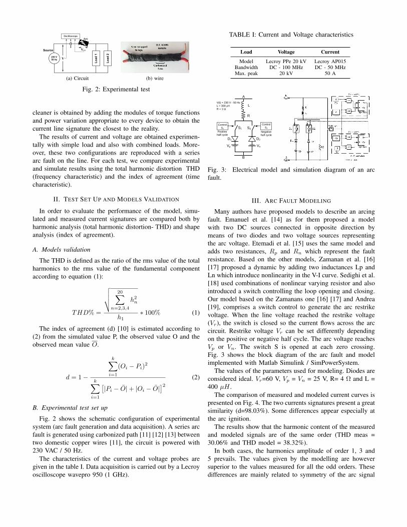
Fig. 2: Experimental test
cleaner is obtained by adding the modules of torque functionsand power variation appropriate to every device to obtain thecurrent line signature the closest to the reality.
The results of current and voltage are obtained experimen-tally with simple load and also with combined loads. More-over, these two configurations are reproduced with a seriesarc fault on the line. For each test, we compare experimentaland simulate results using the total harmonic distortion THD(frequency characteristic) and the index of agreement (timecharacteristic).
II. TEST SET UP AND MODELS VALIDATION
In order to evaluate the performance of the model, simu-lated and measured current signatures are compared both byharmonic analysis (total harmonic distortion- THD) and shapeanalysis (index of agreement).
A. Models validation
The THD is defined as the ratio of the rms value of the totalharmonics to the rms value of the fundamental componentaccording to equation (1):
THD% =
√√√√ 20∑n=2,3,4
h2n
h1∗ 100% (1)
The index of agreement (d) [10] is estimated according to(2) from the simulated value P, the observed value O and theobserved mean value O.
d = 1−
k∑i=1
(Oi − Pi)2
k∑i=1
[|Pi − O|+ |Oi − O|
]2 (2)
B. Experimental test set up
Fig. 2 shows the schematic configuration of experimentalsystem (arc fault generation and data acquisition). A series arcfault is generated using carbonized path [11] [12] [13] betweentwo domestic copper wires [11], the circuit is powered with230 VAC / 50 Hz.
The characteristics of the current and voltage probes aregiven in the table I. Data acquisition is carried out by a Lecroyoscilloscope wavepro 950 (1 GHz).
TABLE I: Current and Voltage characteristics
Load Voltage Current
Model Lecroy PPe 20 kV Lecroy AP015Bandwidth DC - 100 MHz DC - 50 MHzMax. peak 20 kV 50 A
R
Vp Vn
S2
L
S1
B
A
D1 D2
V(t) = 230 V - 50 Hz
L = 300 μH
R = 1
Control
S1
Control
S2
Positive
half cycleNegative
half cycle
Fig. 3: Electrical model and simulation diagram of an arcfault.
III. ARC FAULT MODELING
Many authors have proposed models to describe an arcingfault. Emanuel et al. [14] as for them proposed a modelwith two DC sources connected in opposite direction bymeans of two diodes and two voltage sources representingthe arc voltage. Etemadi et al. [15] uses the same model andadds two resistances, Rp and Rn which represent the faultresistance. Based on the other models, Zamanan et al. [16][17] proposed a dynamic by adding two inductances Lp andLn which introduce nonlinearity in the V-I curve. Sedighi et al.[18] used combinations of nonlinear varying resistor and alsointroduced a switch controlling the loop opening and closing.Our model based on the Zamanans one [16] [17] and Andrea[19], comprises a switch control to generate the arc restrikevoltage. When the line voltage reached the restrike voltage(Vr), the switch is closed so the current flows across the arccircuit. Restrike voltage Vr can be set differently dependingon the positive or negative half cycle. The arc voltage reachesVp or Vn. The switch S is opened at each zero crossing.Fig. 3 shows the block diagram of the arc fault and modelimplemented with Matlab Simulink / SimPowerSystem.
The values of the parameters used for modeling. Diodes areconsidered ideal. Vr=60 V, Vp = Vn = 25 V, R= 4 Ω and L =400 µH .
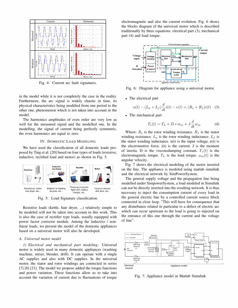
The comparison of measured and modeled current curves ispresented on Fig. 4. The two currents signatures present a greatsimilarity (d=98.03%). Some differences appear especially atthe arc ignition.
The results show that the harmonic content of the measuredand modeled signals are of the same order (THD meas =30.06% and THD model = 38.32%).
In both cases, the harmonics amplitude of order 1, 3 and5 prevails. The values given by the modelling are howeversuperior to the values measured for all the odd orders. Thesedifferences are mainly related to symmetry of the arc signal
Current Harmonic
Measured
Modeled
Fig. 4: Current arc fault signatures.
in the model while it is not completely the case in the reality.Furthermore, the arc signal is widely chaotic in time, itsphysical characteristics being modified from one period to theother one, phenomenon which is not taken into account in themodel.
The harmonics amplitudes of even order are very low aswell for the measured signal and the modelled one. In themodelling, the signal of current being perfectly symmetric,the even harmonics are equal to zero.
IV. DOMESTIC LOAD MODELING
We have used the classification of all domestic loads pro-posed by Ting et al. [20] based on four types of loads (resistive,inductive, rectified load and motor) as shown in Fig. 5.
Fig. 5: Load Signature classification.
Resistive loads (kettle, hair dryer, ...) relatively simple tobe modeled will not be taken into account in this work. Thisis also the case of rectifier type loads, usually equipped withpower factor corrector module. Among the inductive / non-linear loads, we present the model of the domestic appliancesbased on a universal motor will also be developed.
A. Universal motor model
1) Electrical and mechanical part modeling: Universalmotor is widely used in many domestic appliances (washingmachine, mixer, blender, drill). It can operate with a singleAC supplies and also with DC supplies. In the universalmotor, the stator and rotor windings are connected in series[7] [8] [21]. The model we propose added the torque functionsand power variation. These functions allow us to take intoaccount the variation of current due to fluctuations of torque
electromagnetic and also the current evolution. Fig. 6 showsthe blocks diagram of the universal motor which is describedtraditionally by three equations: electrical part (3), mechanicalpart (4) and load torque.
Fig. 6: Diagram for appliance using a universal motor.
• The electrical part
u(t)− (La + Lf )d
dti(t)− e(t) = (Ra +Rf )i(t) (3)
• The mechanical part
Te(t) = TL +D ∗ wm + Jd
dtwm (4)
Where: Ra is the rotor winding resistance. Rf is the statorwinding resistance. La is the rotor winding inductance. Lf isthe stator winding inductance. u(t) is the input voltage. e(t) isthe electromotive force. i(t) is the current. J is the momentof inertia. D is the viscousdamping constant. Te(t) is theelectromagnetic torque. TL is the load torque. ωm(t) is theangular velocity.
Fig. 7 shows the electrical modeling of the motor insertedon the line. The appliance is modeled using matlab simulinkand the electrical network by SimPowerSystem.
The general supply voltage and the propagation line beingmodelled under SimpowerSystem, a load modeled in Simulinkcan not be directly inserted into the resulting network. It is thusnecessary to inject the consumption current of every load inthe general electric line by a controlled current source blockconnected in close loop. ”This will have for consequence thatany disturbance related in particular to a defect of electric arcwhich can occur upstream to the load is going to injected onthe entrance of this one through the current and the voltageof line”.
2electricalnetwork
L2
1electricalnetwork
L1v+
-
Voltagemotor
v+-
TL0
wTL
Torque_Load_TL
TL0
TL0 [Nm]
Load Torque
i
flux
Ka
w
Mechanical part
Current
Measure
Voltage
Measure
[0]
IC
Voltage
w
i
flux
k
Electrical part
i+ -
Current
ControlledCurrentSource
V_ref
In Out
PowerControl
ACSource
Appliance modelElectrical
network
SimPowerSystem
Simulink
s -+
Fig. 7: Appliance model in Matlab Simulink
V. RESULTS
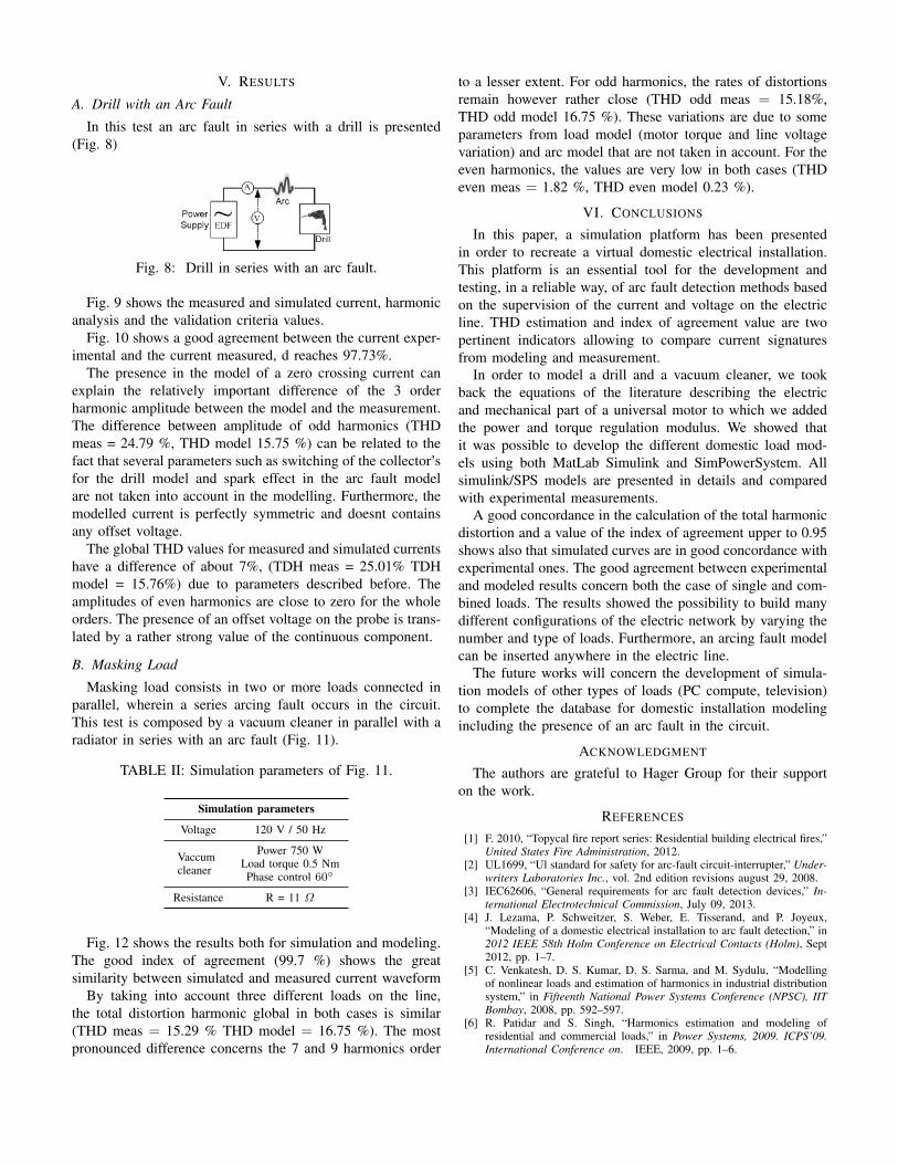
A. Drill with an Arc Fault
In this test an arc fault in series with a drill is presented(Fig. 8)
Fig. 8: Drill in series with an arc fault.
Fig. 9 shows the measured and simulated current, harmonicanalysis and the validation criteria values.
Fig. 10 shows a good agreement between the current exper-imental and the current measured, d reaches 97.73%.
The presence in the model of a zero crossing current canexplain the relatively important difference of the 3 orderharmonic amplitude between the model and the measurement.The difference between amplitude of odd harmonics (THDmeas = 24.79 %, THD model 15.75 %) can be related to thefact that several parameters such as switching of the collector’sfor the drill model and spark effect in the arc fault modelare not taken into account in the modelling. Furthermore, themodelled current is perfectly symmetric and doesnt containsany offset voltage.
The global THD values for measured and simulated currentshave a difference of about 7%, (TDH meas = 25.01% TDHmodel = 15.76%) due to parameters described before. Theamplitudes of even harmonics are close to zero for the wholeorders. The presence of an offset voltage on the probe is trans-lated by a rather strong value of the continuous component.
B. Masking Load
Masking load consists in two or more loads connected inparallel, wherein a series arcing fault occurs in the circuit.This test is composed by a vacuum cleaner in parallel with aradiator in series with an arc fault (Fig. 11).
TABLE II: Simulation parameters of Fig. 11.
Simulation parameters
Voltage 120 V / 50 Hz
Vaccumcleaner
Power 750 WLoad torque 0.5 NmPhase control 60
Resistance R = 11 Ω
Fig. 12 shows the results both for simulation and modeling.The good index of agreement (99.7 %) shows the greatsimilarity between simulated and measured current waveform
By taking into account three different loads on the line,the total distortion harmonic global in both cases is similar(THD meas = 15.29 % THD model = 16.75 %). The mostpronounced difference concerns the 7 and 9 harmonics order
to a lesser extent. For odd harmonics, the rates of distortionsremain however rather close (THD odd meas = 15.18%,THD odd model 16.75 %). These variations are due to someparameters from load model (motor torque and line voltagevariation) and arc model that are not taken in account. For theeven harmonics, the values are very low in both cases (THDeven meas = 1.82 %, THD even model 0.23 %).
VI. CONCLUSIONS
In this paper, a simulation platform has been presentedin order to recreate a virtual domestic electrical installation.This platform is an essential tool for the development andtesting, in a reliable way, of arc fault detection methods basedon the supervision of the current and voltage on the electricline. THD estimation and index of agreement value are twopertinent indicators allowing to compare current signaturesfrom modeling and measurement.
In order to model a drill and a vacuum cleaner, we tookback the equations of the literature describing the electricand mechanical part of a universal motor to which we addedthe power and torque regulation modulus. We showed thatit was possible to develop the different domestic load mod-els using both MatLab Simulink and SimPowerSystem. Allsimulink/SPS models are presented in details and comparedwith experimental measurements.
A good concordance in the calculation of the total harmonicdistortion and a value of the index of agreement upper to 0.95shows also that simulated curves are in good concordance withexperimental ones. The good agreement between experimentaland modeled results concern both the case of single and com-bined loads. The results showed the possibility to build manydifferent configurations of the electric network by varying thenumber and type of loads. Furthermore, an arcing fault modelcan be inserted anywhere in the electric line.
The future works will concern the development of simula-tion models of other types of loads (PC compute, television)to complete the database for domestic installation modelingincluding the presence of an arc fault in the circuit.
ACKNOWLEDGMENT
The authors are grateful to Hager Group for their supporton the work.
REFERENCES
[1] F. 2010, “Topycal fire report series: Residential building electrical fires,”United States Fire Administration, 2012.
[2] UL1699, “Ul standard for safety for arc-fault circuit-interrupter,” Under-writers Laboratories Inc., vol. 2nd edition revisions august 29, 2008.
[3] IEC62606, “General requirements for arc fault detection devices,” In-ternational Electrotechnical Commission, July 09, 2013.
[4] J. Lezama, P. Schweitzer, S. Weber, E. Tisserand, and P. Joyeux,“Modeling of a domestic electrical installation to arc fault detection,” in2012 IEEE 58th Holm Conference on Electrical Contacts (Holm), Sept2012, pp. 1–7.
[5] C. Venkatesh, D. S. Kumar, D. S. Sarma, and M. Sydulu, “Modellingof nonlinear loads and estimation of harmonics in industrial distributionsystem,” in Fifteenth National Power Systems Conference (NPSC), IITBombay, 2008, pp. 592–597.
[6] R. Patidar and S. Singh, “Harmonics estimation and modeling ofresidential and commercial loads,” in Power Systems, 2009. ICPS’09.International Conference on. IEEE, 2009, pp. 1–6.
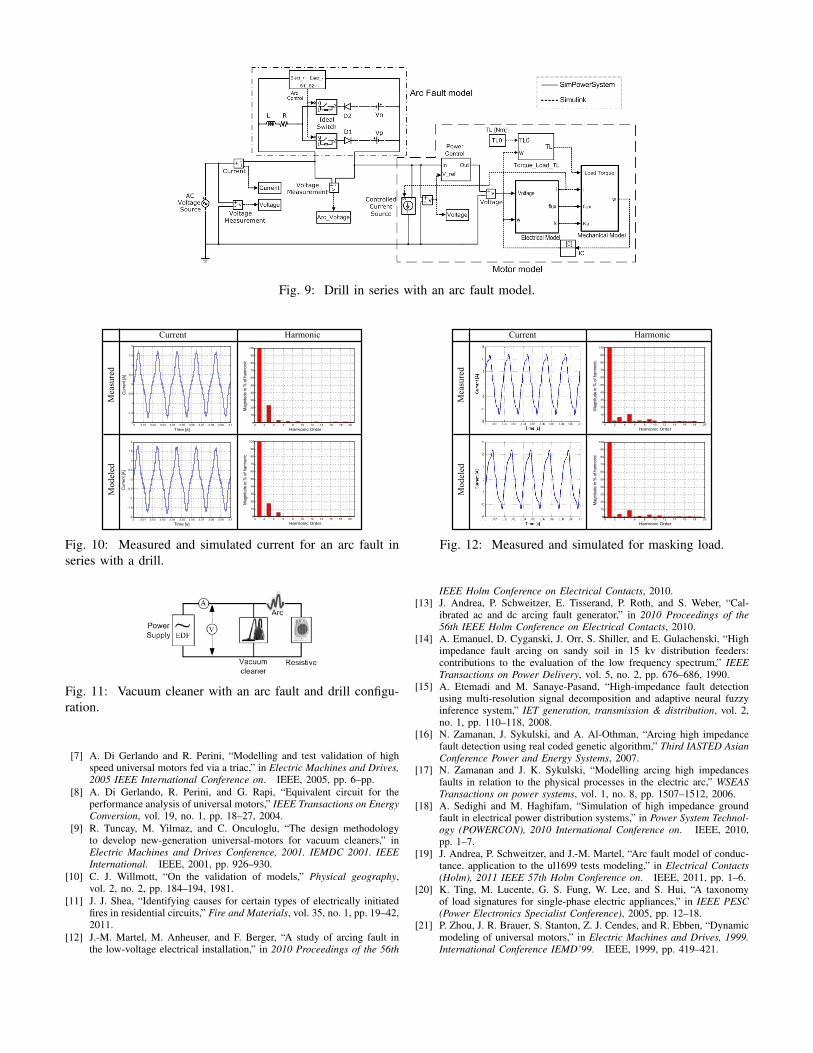
Fig. 9: Drill in series with an arc fault model.
Current Harmonic
Measured
Modeled
3 3.01 3.02 3.03 3.04 3.05 3.06 3.07 3.08 3.09 3.1-2
-1.5
-1
-0.5
0
0.5
1
1.5
2
Time [s]
Cur
rent
[A]
3 3.01 3.02 3.03 3.04 3.05 3.06 3.07 3.08 3.09 3.1-2
-1.5
-1
-0.5
0
0.5
1
1.5
2
Time [s]
Cur
rent
[A]
0 2 4 6 8 10 12 14 16 18 200
10
20
30
40
50
60
70
80
90
100
Harmonic Order
Mag
nitu
de in
% o
f har
mon
ic
0 2 4 6 8 10 12 14 16 18 200
10
20
30
40
50
60
70
80
90
100
Harmonic Order
Mag
nitu
de in
% o
f har
mon
ic
Fig. 10: Measured and simulated current for an arc fault inseries with a drill.
Fig. 11: Vacuum cleaner with an arc fault and drill configu-ration.
[7] A. Di Gerlando and R. Perini, “Modelling and test validation of highspeed universal motors fed via a triac,” in Electric Machines and Drives,2005 IEEE International Conference on. IEEE, 2005, pp. 6–pp.
[8] A. Di Gerlando, R. Perini, and G. Rapi, “Equivalent circuit for theperformance analysis of universal motors,” IEEE Transactions on EnergyConversion, vol. 19, no. 1, pp. 18–27, 2004.
[9] R. Tuncay, M. Yilmaz, and C. Onculoglu, “The design methodologyto develop new-generation universal-motors for vacuum cleaners,” inElectric Machines and Drives Conference, 2001. IEMDC 2001. IEEEInternational. IEEE, 2001, pp. 926–930.
[10] C. J. Willmott, “On the validation of models,” Physical geography,vol. 2, no. 2, pp. 184–194, 1981.
[11] J. J. Shea, “Identifying causes for certain types of electrically initiatedfires in residential circuits,” Fire and Materials, vol. 35, no. 1, pp. 19–42,2011.
[12] J.-M. Martel, M. Anheuser, and F. Berger, “A study of arcing fault inthe low-voltage electrical installation,” in 2010 Proceedings of the 56th
Current Harmonic
Measured
Modeled
0 2 4 6 8 10 12 14 16 18 200
10
20
30
40
50
60
70
80
90
100
Harmonic Order
Mag
nitu
de in
% o
f har
mon
ic
0 2 4 6 8 10 12 14 16 18 200
10
20
30
40
50
60
70
80
90
100
Harmonic Order
Mag
nitu
de in
% o
f har
mon
ic
Fig. 12: Measured and simulated for masking load.
IEEE Holm Conference on Electrical Contacts, 2010.[13] J. Andrea, P. Schweitzer, E. Tisserand, P. Roth, and S. Weber, “Cal-
ibrated ac and dc arcing fault generator,” in 2010 Proceedings of the56th IEEE Holm Conference on Electrical Contacts, 2010.
[14] A. Emanuel, D. Cyganski, J. Orr, S. Shiller, and E. Gulachenski, “Highimpedance fault arcing on sandy soil in 15 kv distribution feeders:contributions to the evaluation of the low frequency spectrum,” IEEETransactions on Power Delivery, vol. 5, no. 2, pp. 676–686, 1990.
[15] A. Etemadi and M. Sanaye-Pasand, “High-impedance fault detectionusing multi-resolution signal decomposition and adaptive neural fuzzyinference system,” IET generation, transmission & distribution, vol. 2,no. 1, pp. 110–118, 2008.
[16] N. Zamanan, J. Sykulski, and A. Al-Othman, “Arcing high impedancefault detection using real coded genetic algorithm,” Third IASTED AsianConference Power and Energy Systems, 2007.
[17] N. Zamanan and J. K. Sykulski, “Modelling arcing high impedancesfaults in relation to the physical processes in the electric arc,” WSEASTransactions on power systems, vol. 1, no. 8, pp. 1507–1512, 2006.
[18] A. Sedighi and M. Haghifam, “Simulation of high impedance groundfault in electrical power distribution systems,” in Power System Technol-ogy (POWERCON), 2010 International Conference on. IEEE, 2010,pp. 1–7.
[19] J. Andrea, P. Schweitzer, and J.-M. Martel, “Arc fault model of conduc-tance. application to the ul1699 tests modeling,” in Electrical Contacts(Holm), 2011 IEEE 57th Holm Conference on. IEEE, 2011, pp. 1–6.
[20] K. Ting, M. Lucente, G. S. Fung, W. Lee, and S. Hui, “A taxonomyof load signatures for single-phase electric appliances,” in IEEE PESC(Power Electronics Specialist Conference), 2005, pp. 12–18.
[21] P. Zhou, J. R. Brauer, S. Stanton, Z. J. Cendes, and R. Ebben, “Dynamicmodeling of universal motors,” in Electric Machines and Drives, 1999.International Conference IEMD’99. IEEE, 1999, pp. 419–421.