appendix: useful concepts from circuit theory -...
TRANSCRIPT

Appendix: Useful Concepts fromCircuit TheoryEDWIN R. LEWIS
1. Introduction
For understanding the physics of sound and the biophysics of acoustic sensorsin animals, the concepts of impedance and admittance, impedance matching,transducer, transformer, passive and active, bidirectional coupling, and resonanceare widely used. They all arise from the circuit-theory metamodel, which hasbeen applied extensively in acoustics. As the name suggests, the circuit-theorymetamodel provides recipes for constructing models. The example applicationsof the metamodel in this appendix involve a few elementary concepts fromclassical physics: the adiabatic gas law, Newton's laws of motion and of viscosity, and the definitions of work and of Gibbs free energy. They also involvea few elements of calculus and of the arithmetJc of complex numbers. All ofthese should be familiar to modem..biologists t.nd clinicians. For further examples of the application of circuit concepts to acoustical tHeory and acousticaldesign, see Baranek (1954), Olsen (1957), or Morse (1981).
1.1 The Recipe
Applied to an elementary physical process, such as sound conduction in a uniform medium, the appropriate recipe comprises the following steps;
1. Identify an entity (other than Gibbs free energy, see below) that is taken tobe conserved and to move from place to place during the process.
2. Imagine the space in which the process occurs as being divided into suchplaces (i.e., into places in which the conserved entity can accumulate).
3. Construct a map of the space (a circuit graph) by drawing a node (e.g., asmall dot) for each place.
4. Designate one place as the reference or ground place for the process.5. Assign the label "0" to the node representing the ground place.6. Assign a unique, nonzero real integer (i) to each of the other nodes in the
graph.7. Define the potential difference between each place (i) and the ground place
(0) to be FiO' the corresponding Gibbs potential for the conserved entity
369

370 E.R. Lewis
(change in Gibbs free energy of the system per unit of conserved entitymoved from place 0 to place i).
8. From basic physical principles (or by measurement), determine the relationship between the amount, Q•., of conserved entity accumulated at place i andthe potential Fio'
9. From basic physical principles (or by measurement), determine the relationship between potential difference Fij between each pair of neighboring placesand the flow J,.j of conserved entity between those places.
The Gibbs free energy of a system is defined as the total work available fromthe system less that portion of the work that must be done against the atmosphere. For one-dimensional motion from point a to point b, the work (Wab)
done by the system is defined by the expression Wab = J~=a fix)d.x where fix) isthe force applied by the system to the object on which the work is being done.The force is taken to be positive if it is applied in the direction in which thevalues of x increase; otherwise it is taken to be negative. For tables of Gibbspotentials for various conserved entities, see Lewis (1996).
1.2 Example: An Acoustic Circuit Model
As an example application of the recipe, consider the conduction of sound,axially, through an air-filled cylindrical tube with rigid walls. In that case, onemight identify the conserved entity as the air molecules that move from placeto place along tbe tube. As air molecules accumulate at a given place, thepressure at that place increases. Assuming that the air pressure outside the tubeis uniform and equal to atmospheric pressure, it is convenient to take that place(the outside of the tube) to be the reference place. The SI unit for number ofair molecules is 1.0 mol. Therefore, the SI unit for the flow of air moleculeswill be 1.0 moVs; and the SI unit for the Gibbs potential will be 1.0joule/mol.If one takes Pi to be the absolute pressure at place i along the inside of the tube(SI unit 1.0 ntlm2 = 1.0 Pa) and Po to be the absolute atmospheric pressure,then the sound pressure (~i) at place i will be the difference between those twopressures:
~ ..= Pi - Po (1)
Acousticians usually assume that the processes involved in sound propagationare adiabatic and that sound pressures are exceedingly small in comparison toatmospheric pressure:
~i «1.0 (2)Po
The Gibbs potential difference, F iO' between place i and the reference place isgiven by:
(3)

(4)
Appendix: Useful Concepts from Circuit Theory 371
where Co is the resting concentration of air molecules (SI unit = 1.0 mol/m3).
noCo =-
Vo
where no is the resting number of air molecules at place i, and Vo is the volumeof place i (assumed to be constant). The resting absolute pressure at place i istaken to be Po.
Equation 3 for the Gibbs potential can be derived easily from the equationfor work. Invoking the adiabatic gas law, one can derive the relationship between the Gibbs potential at place i and the excess number of air molecules atplace i, tin;, where
(5)
n; being the total number of air molecules at place i. For !!P/Po exceedinglysmall, the adiabatic gas law can be stated as follows:
!!p. tin·-' = y-'Po no
(6)
(7)
where y is 1.4, the ratio of specific heat of air at constant pressure to that atconstant volume. From this,
F = !!Pi = '¥Po tinID.I r
Co Cono
In the circuit-theory metamodel, this is a capacitive relati~nship. The general
constitutive relationship for a linear, shunt capacity at place' i in any c~cuit is
(8)
where the parameter C; often is called the capacitance or compliance. In thiscase, Q;, the accumulation of conserved entity at place i, is taken to be to betin;,
C; = cono'¥Po
(9)
Dividing the cylindrical tube axially into a large number of segments of equalvolume, Vo, brings the first eight steps of the metamodel recipe to completion.For the ninth step one might assume that the acoustic frequencies are sufficientlyhigh to preclude significant propagation of drag effects from the wall of thecylinder into the mainstream of axial air flow. In other words, one might ignorethe effects of viscosity (see subsection 8.2). Absent viscosity, the axial flow ofair molecules would be limited only by inertia. Lumping the total mass of airmolecules at a single place, and invoking Newton's second law of motion, onehas the following relationship for the flow, J ii' of molecules from place i to itsneighboring place, j:

(10)
372 E.R. Lewis
dJ.. Ao2co2=.Jl = -- F.dt VoPo ij
where t is time, Po is the resting density of the air (SI unit equal 1.0 kg/m3),
and Ao is the luminal area of the cylindrical tube. In the circuit-theory metamodel, this is an inertial relationship. The general constitutive relationship fora linear, series inertia between place i and j in any circuit is
F I d}..ij = .,=.!J.I} dt
(11)
(12)
where the parameter Iij often is called the inertia or inertance. In this case,
VoPo
Iij = A2c2o 0
2. Derivation of an Acoustic Wave Equation from theCircuit Model
Having thus completed the circuit model, one now can extract from it an equation describing sound conduction through the tube. This normally is accom
plished by writing expliciJ expressioASfor the conservation of (conserved) entityat node i and the conservation of eaergy in the vicinity of node i, and thenincorporating the constitutive relations obtained in steps 8 and 9 of the metamodel recipe. Let node i have two n~ighbors, node h on its left and node j onits right. Conservation of air molecules requires that
From Equation 8 one notes that
dQi = CdF,udt I dt
Therefore,
Jhi - J .. = CdFiOI} .-I dt
Conservation of energy requires that
Therefore,
FiO-F =I~jO ij dt
(13)
(14)
(15)
(16)
(17)
(18)
(19)
Appendix: Useful Concepts from Circuit Theory 373
2.1 Translation to a Transmission-Line Model
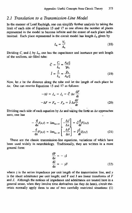
In the manner of Lord Rayleigh, one can simplify further analysis by taking thelimit of each side of Equations 15 and 17 as one allows the number of placesrepresented in the model to become infinite and the extent of each place infinitesimal. Each place represented in the circuit model has length Lo given by
VoLo=-
Ao
Dividing Cj and Ij by Lo, one has the capacitance and inertance per unit lengthof the uniform, air-filled tube:
A Cj AoC5C=-=-Lo 1Po
j = !.L = .2!LLo AoC5
Now, let x be the distance along the tube and let the length of each place be.1x. One can rewrite Equations 15 and 17 as follows:
A dF- LV = J . - J. = C .1x -
h. U dtA dJ
-M = FiO - Po = }t!.x-} dt(20)
I
Dividing each side of each equation by .1x and taking the limit as .1x approacheszero, one has
(21)
These are the classic transmission-line equations, variations of which havebeen used widely in neurobiology. Traditionally, they are written in a moregeneral form:
dF
dx=-zJdJ
dx = - yF(22)
where z is the series impedance per unit length of the transmission line, and y
is the shunt admittance per unit length; and F and J are linear transforms of Fand J. Although the notions of impedance and admittance are treated here in ageneral sense, when they involve time derivatives (as they do here), circuit theorists normally apply them to one of two carefully restricted situations: (1)

374 E.R. Lewis
sinusoidal steady state (a pure tone has been applied for an indefinitely longtime); or (2) zero state (a temporal waveform is applied; at the instant before itbegins, all Fs and is in the circuit model are equal to zero). For sinusoidalsteady state, circuit theorists traditionally use the phasor transform; for zero statethey traditionally use the Laplace transform. Yielding results interpretable directly in terms of frequency, the former is widely used in classical acousticstexts.
2.2 Derivation of the Phasor Transform
The definition of the phasor transform is based on the presumption that exponentiation of an imaginary number, such as ix (where i is the square root of-1), obeys the same rules as exponentiation of a real number (such as x).
Specifically, it is presumed that eix can be evaluated by substituting ix for x inthe Maclaurin series for ex. In that case,
eix = cosx + i sin x
and
cos x = Re{ eix}
where Re{z} is the real 'part of the complex number, z:. -I'
zpa+ib 0,
i = FfRe{z} = a
(23)
(24)
(25)
The phasor transform applies to sinusoidal steady state, with the radial frequencyof the sinusoid being w (SI unit = 1.0 rad/s).
w = 21tf (26)
where f is the conventional frequency (unit = 1.0 Hz). One can represent thephasor transformation as follows:
H(w) = <I>{H(t)}
H(t) = <I>-IH(w) (27)
where the function of frequency, H(w), is the phasor transform of the timefunction H(t). The transform is defined by its inverse
H(t) = <I>-I{H(w)} A Re[H(w)ei""] (28)
Combining this with Equations 23-25, one finds the following basic transformpairs:
<I>{coswt} = I<1>-1{I} = cos wt<I>{A cos(wt + a.)} = Aeiot = A cos a. + iA sin a.
<I>-l{Aeiot} = <1>-1{A cos a. + iA sin a.} = A cos(wt + a.) (29)

(33)
Appendix: Useful Concepts from Circuit Theory 375
Notice that
lP-1{Aei"'BeiP} = AB cos(wt + ex + ~) (30)
Thus, multiplying the phasor transform of a sinusoidal function of time (of anyamplitude and phase) by the factor Aeia corresponds to two mathematical operations on the function itself: (1) multiplying the amplitude of the function bythe factor A, and (2) adding ex radians to the phase of the function. Taking thefirst derivative of any sinusoidal function of time can be described in terms ofthe same two operations: (1) the amplitude of the function is multiplied by w,and (2) Tt/2 radians (90 degrees) are added to the phase of the function. Thus,
{dH(t)} ,7tlP dt = we'2H(w) (31)
Applying Equation 23, one has7t
ei2 = i
(dH(t))lP dt = iwH(w) (32)
2.3 Phasor Transform of the Transmission-Line Model
Based on Equation 32, one can write the transformed version of Equation 21 asfollows: .;
d. A
dx F(x,w)= -iwIJ(x,w)" Id A ~
-J(x,w) =--iwCF(x,w)dx
Thus, for the transmission-line model (Eq. 22), under sinusoidal steady state atradial frequency w, z and y would be written as follows:
z=iwi
y = i wC (34)
To simplify notation in transformed equations, w often is omitted in the arguments of the dependent variables J and F. For z and y both independent of x,as they are taken to be in this case, the spatial solutions to these equationsusually are written in one of two forms:Form 1
J(x) = Ft<x) + F,(x)
Jt<x) = YoFt<x)
Ft<x) = ZJt<x)
J(x) = Jt<x) - J,(x)
J,(x) = YoF,(x)
F,(x) = ZJ,(x)
Zo = :0 = ~
F,(x) = F,(O)erox (35)

376 E.R. Lewis
Form 2
F(x) = F(O) cosh(ro x) - 2oJ(O) sinh(ro x)
J(x) = J(O) cosh(ro x) - Yof(O)sinh(ro x)
20 = ~o = l2.4 Forward and Reverse Waves
(36)
Define the forward direction for the transmission line as the direction of increas
ing values of x. In the first form, Ft<x) and Jt<x) are interpreted as being thepotential and flow components of a wave traveling in the forward direction; F,(x)
and J,(x) are interpreted as the components of a wave traveling in the reversedirection. At any instant, the product Ft<x)Jt<x) of the corresponding time functions is the rate at which the forward wave carries Gibbs free energy (in theforward direction) past location x, and the product F,(x)J,(x) is the rate at whichthe reverse wave carries Gibbs free energy past x (in the reverse direction).
2.4.1 Speed ~f Sound and Characteristic Impedance
For the simple transm~,sion-line model under consideration here, z is purelyinertial and y is purely icapacitive. " The wave components in form 1 of thesolution become
Ft<x) = Ft<O)e-iJjtWX
Fr(x) = F,(O)e+iJjtWX (37)
Both components are sinusoids, radial frequency w. For the forward component,the phase at distance x from the origin lags that at the origin by an amount thatis directly proportional to x. That is the behavior of a wave traveling at constantspeed in the direction of increasing x (the forward direction). For the reversecomponent, the phase at distance x leads that at the origin by an amount proportional to x. That is the behavior of a wave traveling at constant speed in thedirection of decreasing x (the reverse direction). For both components, the amplitude is independent of x. The speed, <\I, of the wave is the same in both cases.The solution is valid for all frequencies, so one can generalize it to waves ofarbitrary shape that travel at constant speed without changing shape:
Fr (X,f) = Fr (O,t - ~)Jr (x,t) = YoFr (x,t)
F,(x,t) = Fr ( O,f + ~)Jr (x,t) = YoFr (x,t) (38)
(39)

Appendix: Useful Concepts from Circuit Theory 377
The parameter Zo, usually called the characteristic impedance, is a positive realnumber in this case. For sinusoidal steady state this implies that at each place(each value of x) along the acoustic path, Ff and Jf are perfectly in phase withone another, as are Fr and Jr' The relationship between Zo and the physicalparameters of the system and its SI unit both depend on the choice one madeat step 1 of the metamodel recipe. If one carries out the model constructioncorrectly, however, the wave speed will be independent of that choice.
3. Alternative Formulations of the Circuit Model
Instead of taking the number of air molecules as the conserved entity, one mighthave taken their mass. Assuming that the density changes induced in the air bythe propagating sound wave are negligible (the analysis in section 2 was basedon the same assumption), acousticians often use fluid volume as the conservedentity (as a surrogate for mass). Sometimes mass itself is used. All of thesechoices lead to equivalent formulations and moving from one to another requiresonly the application of appropriate multiplicative factors. The SI unit of impedance for each choice of conserved entity is easily determined. If the selectedentity were apples, with an SI unit of 1.0 apple, then the SI unit of flow would" Ibe 1.0 apple/s, and the SI unit of Gibbs pot~ntial would, be 1.0 joule/apple. TheSI unit of impedance would be that of Gibbs potential divided by flow-l.Ojoule s per apple2• For the acousticians' choice of volume, the si unit of conserved entity is 1.0 m3• The SI unit of impedance becomes 1.0 joule s per m6•
For the choice made at the beginning of section 1.2 (SI unit of conserved entity= 1.0 mol), the SI unit of impedance is 1.0 joule s/moF.
3.1 Conventional Acousticians' Formulation
To obtain the acousticians' J (SI unit 1.0 m3/s), one divides the J of section 2(SI unit 1.0 mol/s) by Co (SI unit 1.0 mol/m3). To obtain the acousticians' F (SIunit 1.0 joule/m3), one multiplies the F of section 2 (SI unit 1.0 joule/mol) byCo' When these changes are made, the inertance and compliance per unit lengthbecome,
c = AoWo
j = PoAo
and the characteristic impedance, Zo, becomes
(41)

(42)
378 E.R. Lewis
Zo = J'(poPoAo
Recognizing '(po as the adiabatic bulk modulus of an ideal gas at pressure Po'
one can translate Equations 40 and 42 into general expressions for compressional(longitudinal) acoustic waves in fluids:
t = AoED
$= 1:Zo = JEDP
Ao
ED A -v.~o~V
(43)
(44)
where $ is the speed of sound in the fluid; Zo is the characteristic acousticimpedance of the fluid; ED is the fluid's adiabatic bulk modulus; p is its density,and Ao is the cross-sectional area of the acoustic path (the luminal area of thecylindrical tube in the system being modeled here). Once again, these expressions were based on the presumption that changes in the fluid density, p, pro-duced by the waves are exceedingly small. "
3.2 Modeling Perspective
Following a path already well established by physicists, with the circuit-theorymetamodel as a guide, the development to this point has combined that presumption (exceedingly small changes in fluid density) with two conservationprinciples (energy is conserved, matter is conserved) and with two of the empiricallinear laws of physics (the adiabatic form of the ideal gas law-translatedto a form of Hooke's law, and Newton's second law of motion) to reconstructa theory of sound propagation. With the theory constructed, mathematics wasused to determine where that combination of presumptions, principles, and empirical laws would lead. What the analysis showed was that the local elasticand inertial properties of fluids (gases and liquids) should combine to allowspatially extensive sound propagation. It also showed that if that were the case,then the speed of propagation should be related to the elastic and inertial parameters (adiabatic bulk modulus and density) in the specific manner describedin Equation 43. In fact, the derived relationship (Eq. 43) predicts extremelywell the actual speeds of sound in fluids (gases and liquids). This should bolsterone's faith not only in the specific theory, but also in the modeling process itself.It follows the pattern established by Isaac Newton and practiced successfully bycelebrated physical scientists over and over again since his time. Newton com-

Appendix:UsefulConceptsfromCircuitTheory 379
bined a presumption about gravity with a conservation law (momentum is conserved) and with his second law of motion to construct a theory of planetarymotion. He used mathematics to see where that theory would lead. Where itled was directly to Kepler's laws, which are empirical descriptions of the actualmotions of planets. Recently, writing about Newton's Principia, where thistheory and its analysis first were published, a noted physicist said that theastounding conclusion one would draw from the work is the fact that natureobeys the laws of mathematics. I would put it differently. Physical nature appears to behave in an astoundingly consistent manner. In mathematics, mankindhas invented tools that allow concise and precise statements of apparently consistent local behaviors (e.g., empirically derived laws), tools (such as the circuittheory metamodel) that allow those statements to be combined to constructtheories of spatially (in its general sense) more extensive behaviors, and toolsto derive from those theories their predictions. The fact that the predicted behaviors so often match, extremely well, observed behaviors, is attributable tophysical nature's consistency.
Returning to the metamodel and to the first step in the recipe, one can seethat momentum (Newton's choice) is a particularly interesting alternative to betaken as the conserved entity. Newton's second law equates the force two particles exert on one another to the flow of momentum between them, and (fornonrelativistic systems) the Gibbs potential difference for that momentum flowis the difference between the particles' velocities. When one chooses fluid mass,fluid volume, or number of fluid molecules as the, conserved entity, J is proportional to velocity and F is proportional to force. With momentum as thechoice, F is proportional to velocity, J is proportional to for~e. This is anexample of the celebrated duality that arises in the circuit-theorY'metamodel.
4. Generalization to Plane Waves
As long as the consequences of viscosity were negligible, the presence of therigid cylindrical walls posited in the previous subsections had only one effecton the propagation of sound waves through the fluid inside the cylinder. Itforced that propagation to be axial. The transmission-line equations derived forthe fluid in the cylinder would apply perfectly well to propagation of a planewave through any cross-sectional area Ao, normal to the direction of propagation,in an unbounded fluid medium (e.g., air or water). The propagation speed derived for the waves confined to the fluid in the cylinder is the same as it wouldhave been for unconfined plane waves in the same fluid. The expression forcharacteristic impedance (Eq. 44) would apply to an interface, normal to thedirection of propagation, with cross-sectional area Ao. Viewed locally, propagating sound waves usually approximate plane waves, making Equation 44 andits antecedents very general. In an unbounded fluid, however, the propagationof sound waves is not confined to a single coordinate. A local volume in sucha fluid could have sound waves impinging upon it from all directions at o?ce.

380 E.R. Lewis
The instantaneous local sound-pressure component of each of these waves is ascalar, and the pressures from all of the waves together would sum to a singlevalue. The local volume flow component of each wave will now be a vector(having an amplitude and a direction), and the flows from all of the waves wouldsum vectorially, at any given instant (t), to a single amplitude and direction.For a sound wave from a given direction, the local flow of Gibbs free energythrough a cross-sectional area Ao would be given by the product of the localflow vector (J(t» for that wave and the corresponding local Gibbs potential (F(t»for that wave. Notice that the product itself now is a vector, with amplitude anddirection. The direction of the vector is the direction of energy flow. Noticethat it is the same as the direction of J(t) whenever F(t) is positive. The crosssectional area, Ao, would be taken in a plane normal to the direction of energyflow.
4.1 Particle Velocity
Noting that J(t) for a uniform plane wave would be directly proportional to Ao,
one can normalize it to form another variable-flow density ({}(t».
'.'{}(t) = J(t)
Ao(45)
When J is volume flow (the acou~ticians' choice, SI unit = 1.0 m3/s), {} is thesound-induced component of the velocity of the fluid (SI unit = 1.0 mls). Inthat case, it traditionally is labeled the particle velocity. F, in that case (volumetaken to be the conserved entity), is the local sound pressure. Whatever thechoice of conserved entity, the instantaneous product F{} will be a vector whoseamplitude is the instantaneous flow of Gibbs free energy per unit area (SI unit= 1.0 W1m2), and whose direction is the direction of that energy flow.
It is interesting to contemplate the vector sum of particle velocities of severalunrelated sound waves impinging on a small local volume from different directions in an extended fluid. The local sound pressure would vary in time muchas it might for a plane wave. The particle-velocity vector, on the other hand,would vary not only in amplitude, but also in direction. Try to imagine thecomputational task one would face trying to reconstruct the original sound wavesfrom the combination of that scalar function, F(t), and that vector function, {}(t).
4.2 Particle Displacements
For an acoustical sine wave, the local particle velocity is a sinusoidal functionof time, as is the corresponding local particle displacement, 8(x,t). One cancompute the amplitude, D(x), of the latter directly from the amplitude, B(x), ofthe former:

Appendix: Useful Concepts from Circuit Theory 381
{}(X,t) = B(x)cos(wt)
8(x,t) = D(x)sin(wt) = J{}(x,t)dt = B(x)sin(wt)w
D(x) = B(x)w
(46)
(47)
This, in turn, can be related to the local peak sound pressure, t1p(x), through thecharacteristic impedance:
F(x,t) = t1p(x)cos(wt)
{}(x t) = J(x,t) = F(x,t) = F(x,t), Ao AoZo j EBP
B(x) = t1p(x)jEBP
D(x) = t1p(x)wjEBP
rr-;;. EByEBP = P<1> = ~
In water, p is approximately 103 kg/m3 and <1> is approximately 1.5 X 10³ mis,making P<1> approximatelly 1.5 X 10⁶ kg/m2s. Standard pressure of 1.0 atm isdefined to be 101,325 Pa. The velocity of sound in dry air at 1.0 atm and 20°Cis approximately 340 mls. Therefore, for dry air at 1.0 atm and 20°C, Ei<1>
(which is 1.4pol<1» is approximately 400 kg/m2s .. For a giv~n sound pressure,this means that the peak local particle displacement in air ~U be almost 4000times as great as it is in water.
For a lOO-Hztone with a peak sound pressure of 1.0 Pa (the upper end ofthe usual sound intensity range), for example, the peak local particle displacement in water would be approximately 10 om. In air, it would be 40 /lm. ForI-kHz tones, those particle displacements would be 1 nm and 4 /lm, respectively,and for 10kHz they would be 0.1 nm and 0.4 /lm. At the nominal thresholdlevel for human hearing (0.00003 Pa) at 1.0 kHz, they would be 0.03 pm and0.12 nm. If an evolving animal were able to couple a strain-sensitive device(neural transducer) directly to a flexible structure (e.g., a cuticular sensillum, anantenna, hair) projecting into the air, then a sense of hearing could evolve basedon direct coupling of particle-velocity to that structure. One would guess thatsuch a sense would be limited to low-frequency, high-intensity sounds. For astrain-sensitive device (e.g., a bundle of stereovilli) projected into water, on theother hand, an evolving sense of hearing based on direct coupling of particlevelocity to that device would be much more limited (4,000 times less effectiveat every frequency, every intensity). For such a device, one might expect evolution to have incorporated auxiliary structures to increase the displacement ofthe strain-sensor well beyond the particle displacement of the acoustic wave inthe medium. For detection of airborne sound, such auxiliary structures alsowould have to include a mechanism for transferring acoustic energy from the

382 E.R. Lewis
air to the strain sensor. In the language of the circuit-theory metamodel, thelatter would be a transducer, the former a transformer or an amplifier.
5. Passive Transducers
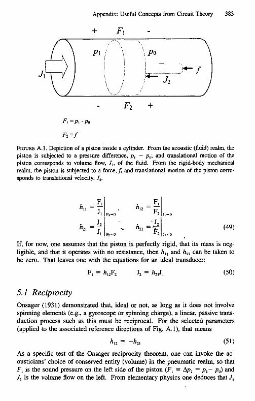
In the basic circuit model, one tracks the flow of a single entity from place toplace. By taking F to be the Gibbs potential for that entity, one is able to trackthe flow of Gibbs free energy as well. The conserved entity will be confinedto a particular realm. Air molecules, for example, are confined to the volumecontaining the air, which one might label the pneumatic realm. The Gibbs freeenergy (acoustic energy) that they carry, on the other hand, can be transferredin and out of that realm. In the circuit-theory metamodel, a device that transfersenergy from one physical realm to another is a transducer. A piston can bemodeled as such a device. It can translate sound pressure, FI' and flow of airmolecules, JI, in a pneumatic realm to a Gibbs potential, F2' and flow, J2, appropriate to a translational rigid-body mechanical realm, and vice versa. Indoing so, it carries Gibbs free energy back and forth between those two realms.For a rigid-body mechanical realm, there are two common choices for conservedentity: (1) the shapes of the rigid elements, or (2) momentum. In rigid-bodymechanics, it is convehient to treat each of the orthogonal directions of translational and rotational motion as',a separate l'ealm. For the piston, the motionof interest is axial (translational mbtion perpendicular to the face of the piston).Following standard engineering practice, one would select axial displacement asthe conserved entity (as a surrogate for shape, displacement is conserved as itpasses through an element whose shape does not change). The SI unit of displacement is 1.0 m. The flow, J2, becomes axial velocity (SI unit = 1.0 m/s);and the Gibbs potential, F2' becomes force (SI unit = 1.0 joule/m). The directions assigned in Fig. A.l are the conventional associated reference directionsfor the circuit-theory construction known as a two-port element. When FI ispositive, it tends to push the piston to the right, the direction assigned to positivevalues of J\. When F2 is positive, it tends to push the piston to the left, thedirection assigned to positive values of J2•
Constitutive relationships for the piston can be expressed conveniently in thefollowing form:
FI = hl1JI + h12F2
J2 = h21JI + h22F2 (48)
where the parameters h\2 and h21 are transfer relationships; hl1 is an impedance(ratio of a Gibbs potential to the corresponding flow); and h22 is an admittance(ratio of a flow to the corresponding Gibbs potential). One estimates these
parameters individually (by measurement or by invoking simple physics) fromthe following equations:
Appendix: Useful Concepts from Circuit Theory 383
't-+- fI j~ - -----------------
!+- J2I
\\
I
\\
PI (!
FIGUREA.!. Depiction of a piston inside a cylinder. From the acoustic (fluid) realm, thepiston is subjected to a pressure difference, PI - Po; and translational motion of thepiston corresponds to volume flow, J" of the fluid. From the rigid-body mechanicalrealm, the piston is subjected to a force, f, and translational motion of the piston corresponds to translational velocity, J2•
(49)
If, for now, one assumes that the piston is perfectly rigid, that its mass is negligible, and that it operates with no resistance, then hu and h22 can be taken tobe zero. That leaves one with the equations for an ideal transducer:
(50)
5.1 Reciprocity
Onsager (1931) demonstrated that, ideal or not, as long as it does not involvespinning elements (e.g., a gyroscope or spinning charge), a linear, passive transduction process such as this must be reciprocal. For the selected parameters(applied to the associated reference directions of Fig. A.l), that means
(51)
As a specific test of the Onsager reciprocity theorem, one can invoke the acousticians' choice of conserved entity (volume) in the pneumatic realm, so thatFI is the sound pressure on the left side of the piston (F1 = ¥l = Pl- Po)andJ1 is the volume flow on the left. From elementary physics one deduces that J.
(52)
(53)
384 E.R. Lewis
will be zero when Fl (the net pressure pushing from the left) times the luminalarea, Ao, is equal to the force pushing from the right. Therefore,
FI/h =-
IZ Fz J,=o Ao
When there is no force from the right (Fz is zero), so that the piston could notbe deformed even if it were not perfectly rigid, then from elementary geometryone knows that the (rightward) volume flow into the piston, JI, must equal theluminal area, Ao, times the rightward velocity of the piston. Therefore,
JzlhZI = JI 1'2=0
and h,z = -hz" as the Onsager theorem says it must.
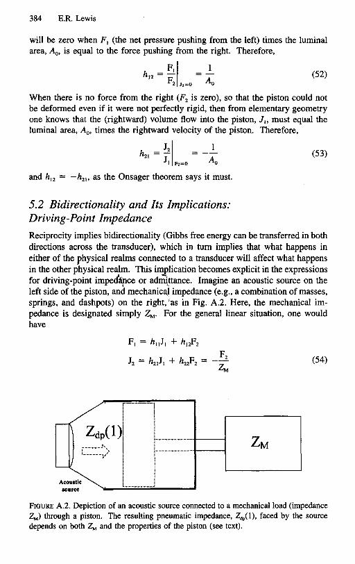
5.2 Bidirectionality and Its Implications:Driving-Point Impedance
Reciprocity implies bidirectionality (Gibbs free energy can be transferred in bothdirections across the transducer), which in turn implies that what happens in
either of the physical realms connected to a transducer will affect what happensin the other physical realm. This implication becomes explicit in the expressionsfor driving-point impedApce or ad~~ance. Imagine an acoustic source on theleft side of the piston, and mechanical impedance (e.g., a combination of masses,springs, and dashpots) on the right, 'as in Fig. A.2. Here, the mechanical impedance is designated simply~. For the general linear situation, one wouldhave
(54)
...·-·"'·-·"'·"'1
I1I,ii,"'."' '"
~._-"' .
i
Ii",..I
FIGURE A.2. Depiction of an acoustic source connected to a mechanical load (impedance~) through a piston. The resulting pneumatic impedance, ZdP(l), faced by the sourcedepends on both ~ and the properties of the piston (see text).

(55)
(56)
(58)
Appendix: Useful Concepts from Circuit Theory 385
from which
Z (1) = FI = h _ hl2h21dp JI 11 h22 + 1I~
where ZdP(1) is the (driving-point) impedance that the acoustic source faces asit drives the transducer from the pneumatic realm. It should not be surprising
that ZdP(1) depends strongly on what is connected to the transducer in the otherrealm (Le., on ~). For this passive transducer (which has no spinning elements), with hll and h22 both equal zero,
~ZdP(1) = A5
Note that with the current choices of conserved entities (volume in the pneumaticrealm, axial displacement in the rigid-body mechanical realm) the SI unit of
ZdP(1) is 1.0 joule s per m6 and that of ~ is 1.0 joule s per m2• The factorlIA5 translates the rigid-body mechanical impedance, ~, into the pneumatic
impedance, ZdP(1).
6. Terminal Impedances and Reflected Waves
Imagine the piston with its very short cylinder (luminal area Ao) connected to
the end (x = L) of an air-filled tube (also with luminal area Ao). ZdP(I) nowforms what is known as a terminal impedance for the aC<!lUsticpath through theair in the tube. Applying form 1 of the transmission-line 'bquation (Eq. 35), onehas
FI = FIL) + F.(L) = ZdP(1)JI JI = JIL) - J.(L)
FIL) = ZJIL) Fr(L) = ZJ.(L) (57)
where FI and JI are the sound pressure and volume flow applied to the pistonby the air in the tube; Zo is the characteristic impedance of the acoustic paththrough the air in the tube. From Equation 57 one can derive the reflectioncoefficient Fr(L)/FIL) of the air-transducer interface:
~ = ZdP(I) - Zo
Ff ZdP(1) + Zo
If the goal is to maximize the transfer of Gibbs free energy from the pneumaticrealm (acoustic energy) to the rigid-body mechanical realm (mechanical energy),then one wants to minimize the amplitude of the reflected wave, Fr. It is clear
from Equation 58 that Fr will be reduced to zero if Zdp(1) = Zo. In other words,there will be no reflection if the acoustic path is terminated with an impedanceequal to the characteristic impedance of the path. If that is not so, one oftencan make it so by inserting an appropriate passive transformer on one side orthe other of the transducer (the piston).

386 E.R. Lewis
6.1 Transformers and Impedance Matching
The simplest passive transformers are constructed as a cascade of two passivetransducers connected back to back. Consider the system depicted in FigureA.3. Here are two rigid-walled cylindrical tubes containing different fluids. Between the two fluids is a cascade of two pistons connected back to back in atranslational rigid-body mechanical realm. Being reversed, the second piston isrepresented by a two-port model in which Fl is force, JI is rightward translational (axial) velocity, F2 is pressure, and J2 is leftward volume flow. In thatcase, if one assumes as before that the piston is perfectly rigid, that its mass isnegligible, and that it operates with no resistance,
IIji1
II
(59)
Applying Equation 55 to this situation (~ becomes Z02)' one finds that themechanical driving-point impedance at the left side of the second piston is
(60)
Applying the same equation to the first piston (the piston is not reversed, ~
becomes ZdP(P2)), one finds that the driving-point impedance at the left side ofthe complete transformer is
(61)
(62)
To avoid reflections of sound waves as they rlass from fluid 1 to fluid 2 throughthe transformer formed by the pistons, one requires
AlAI2 Zo2 = Zol
Substituting the expression for Zo from Equation 44, one can restate this requirement in terms of the densities and adiabatic bulk moduli of the two fluids:
(63)
Z.1 z.,(p 1)Q z,,(p2) c:JZ02
FIGURE A.3. Depiction of an acoustic transformer comprising back-to-back pistons rig
idly connected in the rigid-body mechanical realm. The transformer couples an acousticmedium with characteristic impedance 20, to one with characteristic impedance 202'

Appendix: Useful Concepts from Circuit Theory 387
The symmetry of this relationship implies that when it is true, sound waves passthrough the transformer in either direction without reflection.
Equation 61 is a form of the classic transformer equation, 't being the transformer ratio. By adjusting 't (the ratio of piston areas), one could, in principle,transform any real-valued impedance (2m) to match any other real-valued impedance (e.g., ZOI)' A mechanical transformer in which 't is less than 1.0 is saidto provide mechanical advantage. The passive device that does so compriseseither a single pair of back-to-back passive transducers (a simple machine), ormultiple pairs of such transducers (a compound machine). In addition to pistonsand their relatives (including flexible diaphragms), the repertoire of passive mechanical transducers includes the wheel (transfers free energy between translational and rotational realms), which is the basis of gear systems and pulleysystems, and the semilever-a rigid bar between a fulcrum and a point of applied force (also transfers free energy between translational and rotationalrealms), which is the basis of lever systems. For gear or pulley systems, 't isthe ratio of wheel (e.g., pulley or gear) radii; for lever systems it is the ratio ofsemilever lengths.
7. Driving-Point Impedance of a Terminated Acoustic Path
In the previous subsection, the piston was modeled as a circuit element withtwo distinct ports: port I facing the pneumatic realm, and port 2 facing the rigidbody mechanical realm. The same sort of model can be useful as well in asingle realm. Suppose the length of a fluid-filled, rigid-walled cylindrical tube....were L. If one were concerned only with the acoustic variables (Fs and Js) atthe ends of the tube, one could translate the transmission-line model (Eq. 36)to a two-port model, one port representing one end of the tube, the other portrepresenting the other end. For that purpose, it is useful to use the two-portimpedance (z) parameters instead of the two-port hybrid (h) parameters:
(64)
where FI and J. in Equation 64 correspond to F(O) and J(O), respectively, inEquation 36; F2 and J2 in Equation 64 correspond to F(x) and J(x) in Equation36 when x is set equal to L. The corresponding z parameters are derived asfollows:
FII F(O) IZll = 1." 12~0 = J(O) J(L)~O
J2 = J(L) = 0 = J(O)cosh({zY L) - YoF(O)sinh({zYL)
cosh({zY L)
ZlI = Zosinh({zY L)
Z = FII = F(O)I = Zo (65)21 J2 JI~O J(L) J(O)~O sinh({zY L)
388 E.R. Lewis
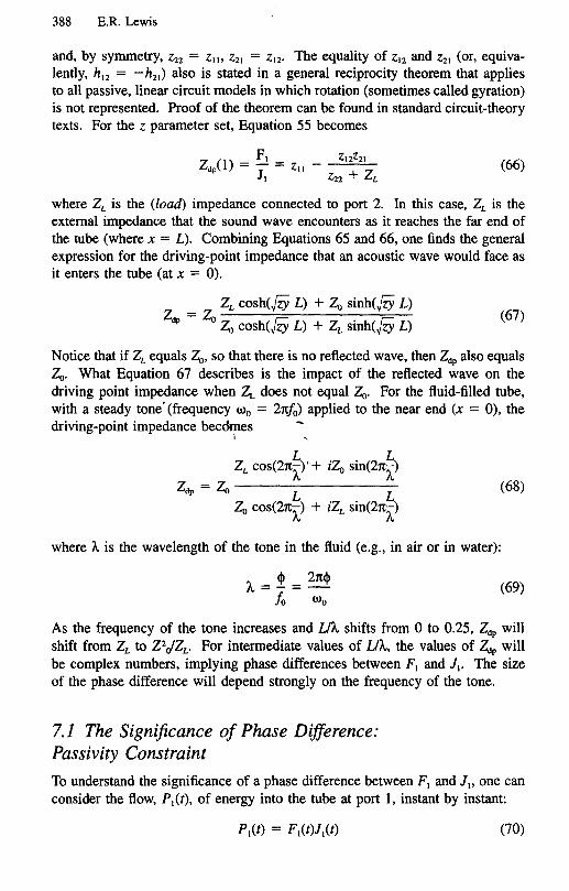
and, by symmetry, zzz = Zw ZZI = ZIZ' The equality of ZIZ and ZZI (or, equivalently, h12 = - hzl) also is stated in a general reciprocity theorem that appliesto all passive, linear circuit models in which rotation (sometimes called gyration)is not represented. Proof of the theorem can be found in standard circuit-theorytexts. For the Z parameter set, Equation 55 becomes
F Z12ZZ1
Z (1) = ~ = ZII - ~Zdp JI ZZZ L(66)
where ZL is the (load) impedance connected to port 2. In this case, ZL is theexternal impedance that the sound wave encounters as it reaches the far end ofthe tube (where x = L). Combining Equations 65 and 66, one finds the generalexpression for the driving-point impedance that an acoustic wave would face asit enters the tube (at x = 0).
ZL cosh(jZY L) + Zo sinh(jZY L)Z = Zo ---------
dp Zo cosh(jZY L) + ZL sinh(jZY L)(67)
Notice that if ZL equals Zo, so that there is no reflected wave, then ZdP also equalsZo. What Equation 67 describes is the impact of the reflected wave on thedriving point impedance when Zr. does not equal Zo. For the fluid-filled tube,with a steady tone' (frequency 000 = 21t/o) applied to the near end (x = 0), thedriving-point impedance becdmesI
(68)
where t.. is the wavelength of the tone in the fluid (e.g., in air or in water):
t.. = ~ - 2m!>
10-000(69)
As the frequency of the tone increases and lit.. shifts from 0 to 0.25, ZdP willshift from ZL to Z2JZL' For intermediate values of lit.., the values of ZdP willbe complex numbers, implying phase differences between FI and J1• The sizeof the phase difference will depend strongly on the frequency of the tone.
7.1 The Significance of Phase Difference:Passivity Constraint
To understand the significance of a phase difference between FI and JI, one canconsider the flow, PI(t), of energy into the tube at port 1, instant by instant:
(70)
(71)
Appendix: Useful Concepts from Circuit Theory 389
From this, one computes the total energy, E" entering the tube over each fullcycle of the sinusoidal waveform. Let
J,(t) = A cos wt
ZdP= Kei[3
FI(t) = KA cos (wt + ~)
In that case,
'(Ii>
J ~ ~E, = KA2 cos(2rcfcl) cos(2rcfcl + ~)dt = 2+ K cos ~ = 2+ Re{ZdP}o :/0:/0
(72)
EI is maximum when ~ = 0; it is positive when 0 < ~ < Tt/2 or 0 > ~ >-Tt/2; it is zero when ~ = Tt/2 or ~ = -Tt/2; and it is negative when Tt/2 < ~< rc or -Tt/2 > ~> -rc. The combination of the tube and Zv as posited here,is passive; it cannot deliver more acoustic energy output than that which hasbeen put into it. Therefore,
Passivity constraint
Which requires simply that
rc rc--s ~s-2 2
",
(73)
(74)
If Zdpwere purely inertial or purely capacitive, then Re{ZdP} would be zero. Inthat case, the energy delivered into the tube during one half cycle will be delivered back out again during the other half cycle.
7.2 The Evolving Ear's Options for MaximizingFree-Energy Transfer
If, under sinusoidal steady-state conditions, one wishes to transfer Gibbs freeenergy from one acoustic path to another, and if the second path is finite inlength (terminated), and if one wishes to use a transformer to translate thedriving-point impedance of the second path to the characteristic impedance ofthe first, so as to maximize free-energy transfer over a wide range of frequencies,then Equations 68 and 72 establish the constraints that are imposed by thephysics of the situation. The driving-point impedance of the second path mustbe a positive real number that is independent of frequency. Assuming Zo is sucha number, there seem to be two ways to make that happen: (1) terminate thesecond path with an impedance equal to the characteristic impedance of thatpath, or (2) make ZL real and make the second path so short that U'A remainsvery small for all frequencies of interest. These would have been the possibil-

390 E.R. Lewis
ities open to evolution as it sculpted the paths and transformers for conveyingacoustic energy into the ear.
8. Wall Effects
8.1 Effects of Wall Compliance
If the wall of the cylinder in the original scheme were compliant, if the diameterof the cylinder were small in comparison to the wavelengths of the sound, andif the pressure outside the wall remained fixed at Po (e.g., atmospheric pressure),then the expression for capacitance per unit length (Eq. 43) would become
A Ao A
C = - + Cwall (75)EB
In other words, the compliance per unit length of the wall would add to that ofthe fluid. In the original formulation, the mass-related conserved entity (mass,particle-population, or volume) was accumulated in local compression of thefluid alone. Now it also is accumulated in local expansion of the cylinder wall.Thus, for a given incremental change in pressure, more of the conserved entitywould be stored per unit length. This would make both the speed of the soundand the characteristic impedance of the sound path smaller than they would bein an extended voiume of the fluid (see Eqs. 39 and 40). In the mammaliancochlea, the local characteristic impedance and speed of the sound wave evi-l "dently are determined almost entirely by the local compliance of the wall (thebasilar membrane in that case), the contributions of the endolymph and perilymph compliance (Le., the compliance of water) being negligible in comparisonto that of the wall. Recall that the wavelength of a tone equals the speed ofsound divided by the frequency of the tone. If the local speed of sound in thecochlea were that of the inner-ear fluids (i.e., in the neighborhood of 1500 m1s),then the wavelength of a 10-kHz tone, for example, would be in the neighborhood of 15 cm-several times the length of the cochlea. In modem cochlearmodels, the actual wavelength of a to-kHz tone is a small fraction of the totalcochlear length, implying that
AoCwan » - (76)
EB
and that the bulk modulus of water contributes almost nothing to the characteristic impedance or the speed of the wave. Among other things, this means thatthe local particle displacements for waves propagating in the cochlear fluids willbe much greater than for similar waves propagating in unbounded aqueous media(see subsection 4.2).
8.2 Effects of Viscosity
For a sinusoidal wave propagating axially in the forward direction through thefluid in the cylinder, the local volume velocity vector, J(x,t), would reverse

Appendix:UsefulConceptsfromCircuitTheory 391
periodically (with the same period as the sine wave). The flow would be in theforward direction for one half cycle (when the local sound pressure, F, waspositive), and in the opposite direction for the next half cycle (when the localsound pressure was negative). In developing the transmission-line model (seeEqs. 10 and 17) one assumed that the frequencies of the sign waves were sufficiently high to avoid the effects of viscosity. Under this assumption, the localaxial particle velocity, -l}(x,t), is independent of distance from the wall of thecylinder. Strictly speaking, this implies the existence of an infinite radial gradient of velocity at the interface between the wall and the fluid. Fluid dynamicists generally assume that the particle velocity of the fluid immediatelyadjacent to the wall must be zero (i.e., that the fluid sticks to the wall), whichwould move the infinite gradient slightly into the fluid itself. Newton's law ofviscosity states that shearing tension, 'tez (tangential force per unit area), betweenfluid layers is directly proportional to the particle velocity gradient taken normalto those layers. For the fluid in the cylinder, this translates to
d-l}
'tel = T1dr(77)
r is the where radial coordinate, with its origin taken to be the central axis ofthe cylinder, and T1 is the viscosity of the fluid. What one has assumed, then,are extremely large (near-infinite) shearing forces in the fluid layers immediatelyadjacent to the wall. These would impose a drM on the more central layers,slowing them down and thus reducing the shear gtadient, d-l}/dr. In this manner,the drag effects would move radially inward, toward the c,rntral axis of thecylinder. If the duration of one half cycle of the-propagating sine wave weresufficiently short, the drag effects would not have time to spread far fr6m thewall. At the end of the half cycle, the particle velocity would reverse and thespreading process would start over again, with shearing forces in the oppositedirection. Throughout the full period of the sine wave, the local axial particlevelocity would be nearly independent of r over most of the cross-sectional area(Ao) of the cylinder. In the development of Equations 10 to 12, it had beenassumed to be independent of r over the entire area.
If the period of the propagating sine wave were sufficiently long, on the otherhand, the drag effects would have time to reach the central axis of the cylinderand approach very close to a steady-state condition known as fully developedflow. Because its effects take time to propagate to the central axis, however,the viscous drag on the wall does not become fully effective until the fluid hasmoved a sufficientdistance from the entrance of the cylindrical tube. For smallamplitude acoustic waves, that distance is comparable to or less than the diameter of the tube (e.g., see Talbot 1996). When the flow through the cylinderis fully developed, the particle velocity is a parabolic function of r (the radialvelocity profile has the shape of a parabola centered on the central axis of thecylinder). The relationship between F (pressure) and J (axial volume flow) inthat case will be given by Poiseuille's equation for flow in a cylinder, '

392 E.R. Lewis
(78)
This is a resistive relationship. Thus, for low-frequency waves, the series impedance, z, in Equation 22 will be resistive rather than inertial. For highfrequency waves it will be inertial, with inertance per unit length given byEquation 41 (see also Eq. 34).
1
IJ
1
1I1
1
I
where f is the frequency of the sine wave. For fixed total volume flow, as thedrag effects spread toward the center of the tube, the volume velocity thereincreases (making up for the reduction in volume velocity near the walls). Thisincreases the effective inertance of the fluid slightly. For frequencies in the
neighborhood of!c (see Eq. 80) acousticians use j = ::0'
dF
dx = -z)
z[ = i21tfPoAo
(79)
1
1
I1
fi
(80)
8.2.1 A Cutoff Frequency fOl\<\,cousticW~ves in Tubes or DuctsWhen
411f=fc =-
C Aop
the magnitudes of the inertial and resistive components of impedance per unitlength will be approximately equal. For long tubes, therefore, the assumptionthat viscous effects can be ignored will be applicable iff> >!c. Iff is comparableto or less than!c, the effects of viscosity will be severe, and the energy of soundwaves in the tube will be dissipated (converted to heat) very quickly. For purewater at 20°C (Table A.l),
TABLE A.I. Properties of pure water.
Temperature (0C) Density (kglm3) Viscosity (kglm s)
3.98
10
15
20
25
30
35
1000.0
999.7
999.1
998.2
997.0
995.7
994.1
0.1567
0.1307
0.1139
0.1002
0.0890
0.0798
0.0719

(82)
Appendix:UsefulConceptsfromCircuitTheory 393
0.0004 (81)!c "'" --;;:;:-
where the cross-sectional area (Ao) of the tube is given in square meters, and Ie
is given in Hz. For a periotic duct whose cross-sectional area is n square millimeters, for example, the cutoff frequency would be approximately 400/n Hz.With Equation 81 in hand, it is interesting to contemplate the cross-sectionalareas of various ducts and canals in both the auditory and the vestibular sidesof the vertebrate inner ear, as well as the canals associated with lateral-linestructures and those in the bases of the antennules of crustaceans (e.g., see Lewis1984; Lewis and Narins 1998).
9. Resonance
9.1 Helmholtz Resonators
When a lumped inertance is connected in series with a lumped capacitance, theresulting impedance is the sum of the impedances of the two elements:
1 1 - w2ICZg{w) = iwI + -,- = -.-
lWC lW
Similarly, when a lumped inertance is cOIll\ectedin parallel with a lumped capacitance, the resulting admittance is the sUm of the admittances of the twoelements: I
".
1Yp(w) = iwC + :-1 =lW
(83)
Zs and Yp approach 0 as w approaches 1/.flC. This means that their reciprocals,Y, and Zp, approach infinity under the same circumstances. This critical valueof w is the resonant frequency, wr,
1
Wr = .flC(84)
A commonly cited acoustic example is a volume of air enclosed in a rigidwalled container, connected to the rest of the acoustic circuit through a short,small-diameter, rigid-walled air-filled tube. This forms a series IC circuit, withthe values of I and C given by Equations 9 and 12, respectively:
w =r (85)
where the subscript 01 refers to the tube, and the subscript 02 refers to theenclosed volume of air. For short tubes, acousticians sometimes apply a correction to account for the momentum carried beyond the end of the tube, re-

394 E.R. Lewis
placing the tube length, 41' with 41 + 1.7Ro1, where Rot is the tube radius.This configuration, known as a Helmoholtz resonance, is used in sound production by animals (Ewing 1989) and some musical instruments (whistle, ocarina,body of violin; see Olson 1967).
Imagine that, beginning at some initial time (t = 0) a constant-amplitude,sinusoidal sound pressure waveform at frequency w, were applied (from a sourceof some sort) at the mouth of the tube (the end of the tube opposite the enclosedvolume). The corresponding volume flow through the tube, into the enclosedvolume, would approximate a ramp-modulated sine wave (e.g., tsinwt). Cycleby cycle, the amplitude of the sinusoidal volume flow of air through the tubewould grow. Correspondingly, the amplitude of the sinusoidal pressure variations in the enclosed volume would grow. Those pressure variations would beprecisely 180 degrees out of phase with the pressure variations at the source (atthe other end of the tube). Thus the two pressure variations would reinforceone another in the creation of a net pressure difference from one end of the tubeto the other. It is that net pressure difference that drives the flow through thetube. The growing flow through the tube and pressure in the enclosure representa growing amount of acoustic energy stored in the resonant system. In theidealized example presented here, with no mechanism for dissipation of acousticenergy, it would continue to accumulate forever; sinusoidal steady state wouldnever occur. In a real situation, at least two things will happen to the acousticenergy: (1) some fraction of it ",ill be con'lerted to heat by viscous resistancein the system, and (2) some fraction will be radiated from the mouth of the tubeand the walls of the enclosure. When the total amount of acoustic energy gainedfrom the source during each cycle is balanced precisely by the acoustic energylost during each cycle, then sinusoidal steady state will have been achieved.
9.2 Standing-Wave Resonators
In the Helmholtz resonator, one presumes that the wavelength of sound at theresonant frequency is very long in comparison to the dimensions of the enclosedvolume and the tube. When that is not so, another form of resonance-a
standing-wave resonance-can occur. Consider, for example, a rigid-walledtube filled with air. The acoustical driving-point impedance of the air in thetube, viewed from one end of the tube, is given by Equation 68. If the otherend of the tube were sealed, making ZL exceedingly large, then the driving-pointimpedance would be approximated very well by the following expression:
(86)

Appendix: Useful Concepts from Circuit Theory 395
which is zero for all values of wavelength (I.. for which the tube length (L) di
vided by wavelength is an odd multiple of one quarter (e.g., UA. = 1/4, 3/4, 5/4... ). The inertial effects on the flow of air in the tube extend slightly beyond
the open end of the tube. Acousticians correct for this by adding (for each openend) 0.82R to L in these expressions, where R is the tube radius (Rayleigh 1926;see Olson 1957). At each one of the corresponding frequencies (see Eq. 69), theacoustic path through the air in the pipe exhibits a resonance. As in the Helmholtz resonator, imagine that, beginning at some initial time (t = 0) a constantamplitude, sinusoidal sound pressure waveform at one of the resonantfrequencies were applied at the mouth of the tube (the open end of the tube).The time course of the amplitude of the corresponding sinusoidal flow would beessentially the same as that of the Helmholtz resonator, growing linearly withtime in the idealized tube. Within the tube would be a standing wave whose amplitude also increases linearly with time. Sinusoidal steady-state conditionswould never be achieved. In a real tube, the energy of the standing wave wouldcontinue to grow until the energy lost to viscous resistance and acoustic radiationduring each cycle of the sound waveform was precisely equal to the energy provided during each cycle by the sound pressure source driving the tube. Sinusoidal steady state would be achieved when that energy balance was achieved.
Standing-wave resonances occur in a wide range of mechanical systems, including flexible strings under tension, rigid bars, stretched membranes, and rigidcircular plates (e.g., see Olson 1957). The resonances in strings and bars areeasily identified by appropriate application of the ,transmission-line model.
10. Active Transducers and Amplifiers-
A circuit model can be used to represent the flow of free energy from physicalrealm to physical realm and from place to place within any given physical realm.For a model of the auditory periphery, one form of free energy that would beof interest would be that which begins as the free energy being carried by anacoustical input signal (e.g., a tone), representing a stimulus applied to the external ear or its piscine equivalent. Any element of the model that merely storesthat energy, dissipates that energy, or transfers that energy from one place toanother or from one physical realm to another is, by definition, passive. Circuitmodels also may include elements in which free energy that originated in theinput signal is used to gate the flow of free energy into the model from anothersource (e.g., a battery of some kind). These often are represented as two-portelements. The free energy that originated in the input signal enters port 1. Thegated energy from the battery flows out of port 2. If ports 1 and 2 are represented in the model as being in the same physical realm (e.g., both in thepneumatic realm), then the element is an (active) amplifier. If the two ports aredepicted as being in different physical realms, then the element is an activetransducer.

396 E.R. Lewis
10.1 Passivity Implies Bidirectionality
The active nature of the two-port element is reflected in its parameters. Amongother things, a passive, linear process must be reciprocal or antireciprocal. Lackof reciprocity or antireciprocity in a linear two-port element implies that theelement is active. As a corollary of the Onsager reciprocity theorem, for example, one can state the following: if a transduction process (I) is not based onspinning elements (e.g., a spinning top or rotating charge), (2) operates linearly(e.g., over a small range about the origin), and (3) is not bidirectional, then itmust be active. Linear, passive transduction processes based on spinning elements are antireciprocal (h12 = h21, Z12 = -Z21) (see Lewis 1996). To be passive,not only must a linear transduction process be bidirectional, it must be eitherreciprocal or antireciprocal (equally effective in both directions).
10.2 Gated Channels Are Active
On the other hand, gated channels are abundant in nervous systems. In circuitmodels, the elements representing gated channels would be active. The mechanical input to a stereovillar bundle in an inner-ear auditory sensor carriesfree energy that originated with the acoustical input to the external ear. Thisinput modulates. the opening and closing of the strain-gated channels, throughwhich flows electric curre~t driven by..the endolymphatic voltage. The sourceof the free energy carried bly the resulting electrical signal (hair cell receptorpotential) is the endolymph battery, not,the acoustical input to the ear. Acoustically derived energy modulates the flow of electrical energy from a battery-aquintessential active transduction process. In some instances the hair cell receptor potential, in turn, is applied to a transducer that produces force and motion in the stereovillar bundle (see Manley and Clack, Chapter I, section 5.l).It is not clear, yet, whether this process is passive, involving merely the transferof free energy from the receptor potential to the mechanical motion of the bundle, or active, involving the gating of energy from some other source, such asan adenosine triphosphate (ATP) battery, to the motion of the bundle.
10.3 Positive Feedback Can Undamp a Resonance forSharper Tuning
Whether or not the reverse transduction process (from receptor potential to stereovillar motion) is active, the forward transduction process (from stereovillarmotion to receptor potential) definitely is. Thus there is a loop in which thereis the possibility of power gain. It has been proposed that such gain couldcompensate, in part, for the power loss that must be imposed by the viscosityof the water surrounding the stereovillar bundle (see Manley and Clack, Chapter1, section 5). Assuming that tuning of the hair cell is accomplished by mechanical resonance associated with the stereovillar bundle, for example, one candepict the essential ingredients of this proposition with the circuit model of

Appendix: Useful Concepts from Circuit Theory 397
(87)
Figure A.4. Here the mechanical side is depicted on the left, the electrical sideon the right. Fin is the force applied to the apex of the bundle by the acousticinput signal; 4 is the mechanical impedance of the bundle. The upper two-portelement represents an idealized active forward transducer [zero driving-pointimpedance into port 1 (left), zero driving-point admittance into port 2 (right),zero coupling from port 2 to port 1]. The lower two-port element represents anidealized active reverse transducer [zero driving-point admittance into port 2(right), zero driving-point impedance into port 1 (left), zero coupling from port1 to port 2]. The hair cell electrical properties are represented by an admittance,fm,which relates the receptor potential, Fm, to the receptor current, Jm. Thetranslational motion (velocity Jb) of the apex of the stereovillar bundle is appliedthrough the mechanical sides of both the forward and reverse transducers. Forthat reason, the corresponding ports are represented as being in series. This inturn means that the force (Fib) developed by the reverse transducer is depictedas being subtracted from the input force:
J = Fin - Fibb 4
Jm = -~(iW)Jb
F = Jm = -~(iW)Jbm fm fm
Fib = ~(iw)Fm =-kn,(iWi.~(iW)Jbm
F = 7 J + F ="{7 _ ~(I~)~(iW»)Jm ~b Ib ~ Y bm •
(88)
If it were a simple resonance, the impedance of the bundle (to very small translational motion of its apex) could be written as follows:
. I4 = Iwlb + -.- + RbIWeb
J,.
hll=O
I-.
h12=O
II+
I
h2l=~(iw)
+~ hzz=O II v_I Fm
II+-
Fin
Jb +Jm
I
++- I~hll=O
Jb
h,z= -km(iw)
hz,=Ohzz=O
FIGURE A.4. Circuit model depicting forward and reverse transduction in a hair cell.
398 E.R. Lewis
where lb is the inertance of the bundle, Cb is its elastic compliance, and Rb isthe resistance of the bundle (owing at least in part to the viscosity of water).With the transducers in place, the relationship between bundle motion (velocity)and input force becomes
Fb
iwlb + _._1_ + Rb _ k.n(iw)~(iw)IWCb ym
(89)
The net resistance, which damps the resonance, is equal to
Rb - Re{ ~~ } (90)
To be effective for undamping the resonance, the quantity Re{ ~~} should begreater than zero and less than Rb' If it is greater than Rb, the resonance willoscillate spontaneously. If it remains in the proper range, the pair of activetransducers will operate as a stable amplifier (Manley and Clack, Chapter 1,section 5). The effect of this on tuning is depicted in Figure A.5, which showsthe phase and amplitude tuning curves of a damped resonance. The bottompanel in Figure A.5 shows the temporal response (e.g., velocity) of the resonanceas its residual energy decays after the input has ceased. Notice that as theresonance becomes less daniped, its tuning peak becomes sharper but it requiresI "more time to rid itself of residual energy. The latter reflects both the advantageand the disadvantage of resonance tuning: It allows the response to an ongoinginput signal to accumulate over time. In a quiet world, where the threshold ofhearing is limited by the internal noise of the ear, this should enhance the abilityof the hearer to detect the presence of the signal. At the same time, it wouldreduce the temporal resolution with which the hearer could follow amplitudechanges in the signal, once the signal has been detected.
I
I1
-j
1j
I1
1II

Appendix: Useful Concepts from Circuit Theory 399
_ 10CO"0-; 0"0:J~ -10E« -20
L0.05
5
-50.05
0.1 0.2
Frequency (kHz)
0.1 0.2
Frequency (kHz)
0.3
0.3
1
0.5
o
-1L
o
I..
100 200 300
Time (ms)
FIGURE A.5. Tuning of a IOO-Hz resonance with a high degree of damping (solid blackline) and a reduced degree of damping (thick gray line). The bottom panel shows thetime course of decay for residual excitation in the resonance.
400 E.R. Lewis
ReferencesBaranek LL (1954) Acoustics. New York: McGraw-Hill.Ewing AW (1989) Arthropod Bioacoustics. Ithaca, NY: Cornell University Press.Lewis ER (1984) Inertial motion sensors. In: Bolis L, Keynes RD, Maddrell SHP (eds)
Comparative Physiology of Sensory Systems. Cambridge: Cambridge UniversityPress, pp.587-61O.
Lewis ER (1996) A brief introduction to network theory. In: Berger SA, Goldsmith W,Lewis ER (eds) Introduction to Bioengineering. Oxford: Oxford University Press,pp.261-338.
Lewis ER, Narins PM (1998) The acoustic periphery of amphibians: anatomy and physiology. In: Fay RR, Popper AN (eds) Comparative Hearing: Fish and Amphibians.New York: Springer-Verlag, pp. 101-154.
Morse PM (1981) Vibration and Sound. New York: Acoustical Society of America.Olson HF (1957) Acoustical Engineering. Princeton, NJ: D. van Nostrand.Olson HF (1967) Music, Physics and Engineering. New York: Dover.Onsager L (1931) Reciprocal relations in irreversible processes: I, II. Phys Rev 37:405
426; 38:2265-2279.Rayleigh (1926) Theory of Sound. London: Arnold.Talbot L (1996) Fundamentals of fluid mechanics. In: Berger SA, Goldsmith W, Lewis
ER (eds) Introduction to Bioengineering. Oxford: Oxford University Press, pp. 101132.
'I'