rf mems for wireless - peoplepeople.eecs.berkeley.edu/~ctnguyen/teaching/tutorials/... ·...
TRANSCRIPT
C. T.-C. Nguyen
RF MEMS for Wireless Communications
iMEMS’01 Short Course
iMEMS’01 Short Course
RF MEMS for Wireless Communications
Instructor: Clark T.-C. Nguyen
Center for Integrated Wireless MicrosystemsDept. of Electrical Engineering and Computer Science
University of MichiganAnn Arbor, Michigan 48109-2122
http://www.eecs.umich.edu/~ctnguyen
C. T.-C. Nguyen
RF MEMS for Wireless Communications
iMEMS’01 Short Course
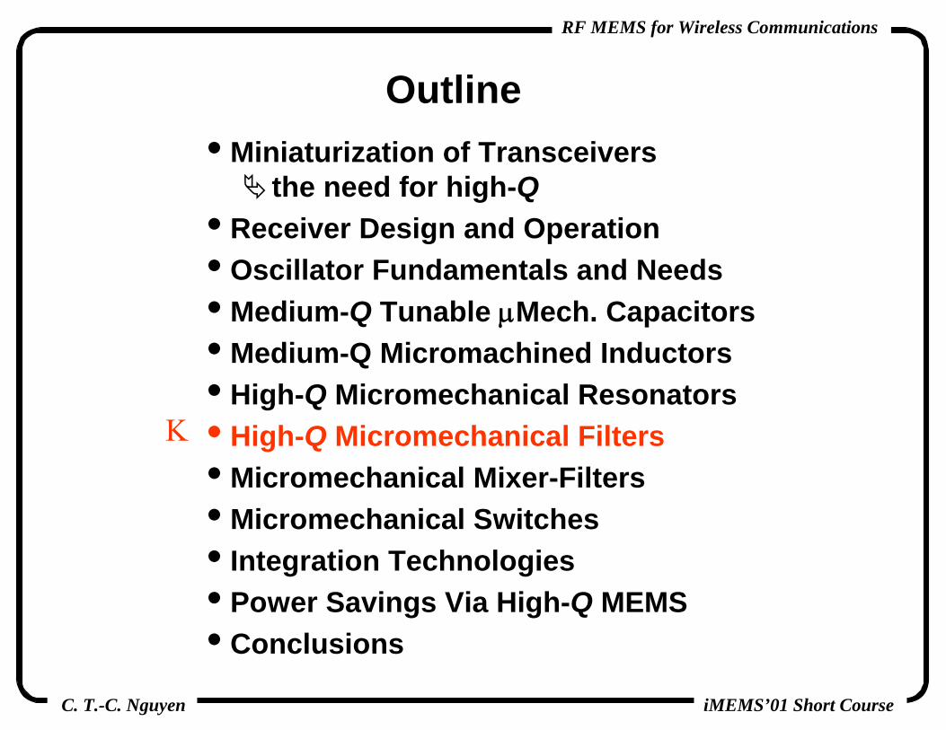
Outline• Miniaturization of Transceivers
the need for high-Q• Receiver Design and Operation• Oscillator Fundamentals and Needs• Medium-Q Tunable μMech. Capacitors• Medium-Q Micromachined Inductors• High-Q Micromechanical Resonators• High-Q Micromechanical Filters• Micromechanical Mixer-Filters• Micromechanical Switches• Integration Technologies• Power Savings Via High-Q MEMS• Conclusions

C. T.-C. Nguyen
RF MEMS for Wireless Communications
iMEMS’01 Short Course
Frequency Division Multiplexed Communications
• Information is transmitted in specific frequency channels within specific bands
TransmittedPower
Frequency
GSM Band DCS1800 BandAdj. BandBand

C. T.-C. Nguyen
RF MEMS for Wireless Communications
iMEMS’01 Short Course
Frequency Division Multiplexed Communications
• Information is transmitted in specific frequency channels within specific bands
TransmittedPower
Frequency
GSM Band DCS1800 BandAdj. BandBand
Filter

C. T.-C. Nguyen
RF MEMS for Wireless Communications
iMEMS’01 Short Course
Frequency Division Multiplexed Communications
• Information is transmitted in specific frequency channels within specific bands
TransmittedPower
Frequency
GSM Band DCS1800 BandAdj. BandBand
Filter
• Need: high frequency selectivity

C. T.-C. Nguyen
RF MEMS for Wireless Communications
iMEMS’01 Short Course
Quality Factor (or Q)• Measure of the frequency
selectivity of a tuned circuit• Definition:
• Example: series LCR circuit
• Example: parallel LCR circuit
dB3CyclePer Lost EnergyCyclePer Energy Total
BWfQ o==
( )( ) CRR
LZZQ
o
o
ωω 1
ReIm
===
( )( ) LGG
CYYQ
o
o
ωω 1
ReIm
===

C. T.-C. Nguyen
RF MEMS for Wireless Communications
iMEMS’01 Short Course
Need for High-Q: Selective Low-Loss Filters
• In resonator-based filters: high tank Q ⇔ low insertion loss
• At right: a 0.3% bandwidth filter @ 70 MHz (simulated)
heavy insertion loss for resonator Q < 5,000

C. T.-C. Nguyen
RF MEMS for Wireless Communications
iMEMS’01 Short Course
Attaining High-Q• Problem: IC’s cannot achieve Q’s in the thousands
transistors consume too much power to get Qon-chip spiral inductors Q’s no higher than ~10off-chip inductors Q’s in the range of 100’s
• Observation: vibrating mechanical resonances Q > 1,000• Example: quartz crystal resonators (e.g., in wristwatches)
extremely high Q’s ~ 10,000 or higher (Q ~ 106 possible)mechanically vibrates at a distinct frequency in a thickness-shear mode

C. T.-C. Nguyen
RF MEMS for Wireless Communications
iMEMS’01 Short Course
Miniaturization of Transceivers
• High-Q functionality required by oscillators and filters cannot be realized using standard IC components use off-chip mechanical components
• SAW, ceramic, and crystal resonators pose bottlenecks against ultimate miniaturization

C. T.-C. Nguyen
RF MEMS for Wireless Communications
iMEMS’01 Short Course
So Many Passive Components!• The total area on a printed circuit board for a
wireless phone is often dominated by passive components passives pose a bottleneck on the ultimate miniaturization of transceivers
TransistorChips
TransistorChips
QuartzCrystalQuartzCrystal
IF Filter(SAW)
IF Filter(SAW)
InductorsCapacitorsResistors
InductorsCapacitorsResistors
IF Filter(SAW)
IF Filter(SAW)
RF Filter(ceramic)RF Filter(ceramic)

C. T.-C. Nguyen
RF MEMS for Wireless Communications
iMEMS’01 Short Course
Surface Micromachining
• Fabrication steps compatible with planar IC processing

C. T.-C. Nguyen
RF MEMS for Wireless Communications
iMEMS’01 Short Course
Post-CMOS Circuits+μMechanics Integration• Completely monolithic, low phase noise, high-Q oscillator
(effectively, an integrated crystal oscillator) [Nguyen, Howe]
• To allow the use of >600oC processing temperatures, tungsten (instead of aluminum) is used for metallization
OscilloscopeOutput
Waveform

C. T.-C. Nguyen
RF MEMS for Wireless Communications
iMEMS’01 Short Course
Micromechanical Resonator Oscillator Video

C. T.-C. Nguyen
RF MEMS for Wireless Communications
iMEMS’01 Short Course
Target Application: Integrated Transceivers
• Off-chip high-Q mechanical components present bottlenecks to miniaturization replace them with μmechanical versions

C. T.-C. Nguyen
RF MEMS for Wireless Communications
iMEMS’01 Short Course
• A large number of off-chip high-Q components replaceable with μmachined versions; e.g., using μmachined resonators, switches, capacitors, and inductors
[Bannon, Clark,Nguyen 1996]
[Young, Boser 1996]
[J.-B. Yoon, et al. 1999]
[Wang, Yu, Nguyen 1999]
[Yao 1997]
MEMS-Replaceable Transceiver Components

C. T.-C. Nguyen
RF MEMS for Wireless Communications
iMEMS’01 Short Course
Outline• Miniaturization of Transceivers
the need for high-Q• Receiver Design and Operation• Oscillator Fundamentals and Needs• Medium-Q Tunable μMech. Capacitors• Medium-Q Micromachined Inductors• High-Q Micromechanical Resonators• High-Q Micromechanical Filters• Micromechanical Mixer-Filters• Micromechanical Switches• Integration Technologies• Power Savings Via High-Q MEMS• Conclusions
Κ

C. T.-C. Nguyen
RF MEMS for Wireless Communications
iMEMS’01 Short Course
Receiver Architectures• Super-Heterodyne:
most widely used architecture for the majority of communication standardsadv.: best performanceproblem: requires many off-chip passive components
• Homodyne: (or zero-IF)mix received signal directly from RF to basebandadv.: removes at least one off-chip passive filter (IF filter); also, relaxes image-reject filter requirementsproblem: dc-offset variation, need for higher dynamic range poorer performance than super-heterodyne
• Wideband IF:uses image-reject mixers, no IF filteradv.: removes IF filter; relaxes image-reject filter req.problem: need image-reject mixers, need higher dynamic range higher power consumption

C. T.-C. Nguyen
RF MEMS for Wireless Communications
iMEMS’01 Short Course
Wireless Receiver Operation
TransmittedPower
FrequencyωRFωLOωIF
RF Pre-Select Filter~945 MHz, Qres ~500RF Pre-Select Filter~945 MHz, Qres ~500
DesiredSignal
ωimage
RF Image-Reject Filter~945 MHz, Qres ~1,000
RF Image-Reject Filter~945 MHz, Qres ~1,000

C. T.-C. Nguyen
RF MEMS for Wireless Communications
iMEMS’01 Short Course
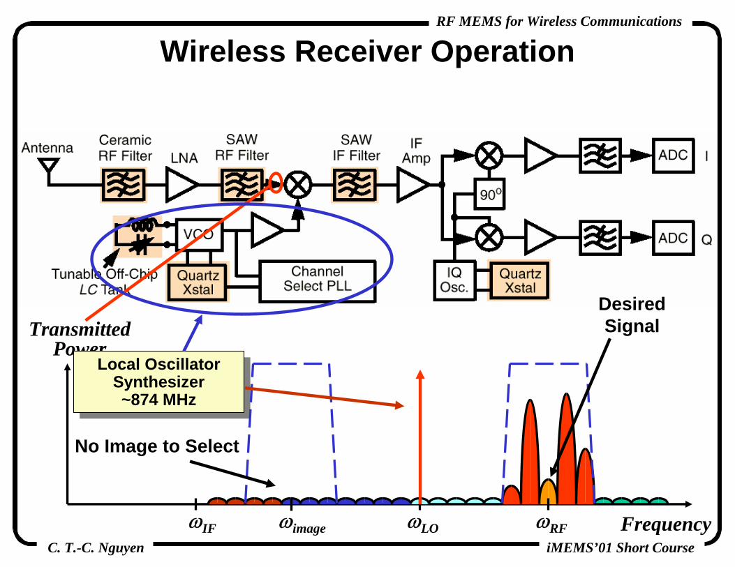
Wireless Receiver Operation
• Question: why not select the channel right at RF?
insufficient Qbut it would be preferred
TransmittedPower
FrequencyωRFωLOωIF
RF Pre-Select Filter~945 MHz, Qres ~500RF Pre-Select Filter~945 MHz, Qres ~500 RF Pre-Select Filter
~945 MHz, Qres ~500RF Pre-Select Filter~945 MHz, Qres ~500
DesiredSignal
ωimage
C. T.-C. Nguyen
RF MEMS for Wireless Communications
iMEMS’01 Short Course
Wireless Receiver Operation
TransmittedPower
FrequencyωRFωLOωIF
Local Oscillator Synthesizer~874 MHz
Local Oscillator Synthesizer~874 MHz
DesiredSignal
ωimage
No Image to Select

C. T.-C. Nguyen
RF MEMS for Wireless Communications
iMEMS’01 Short Course
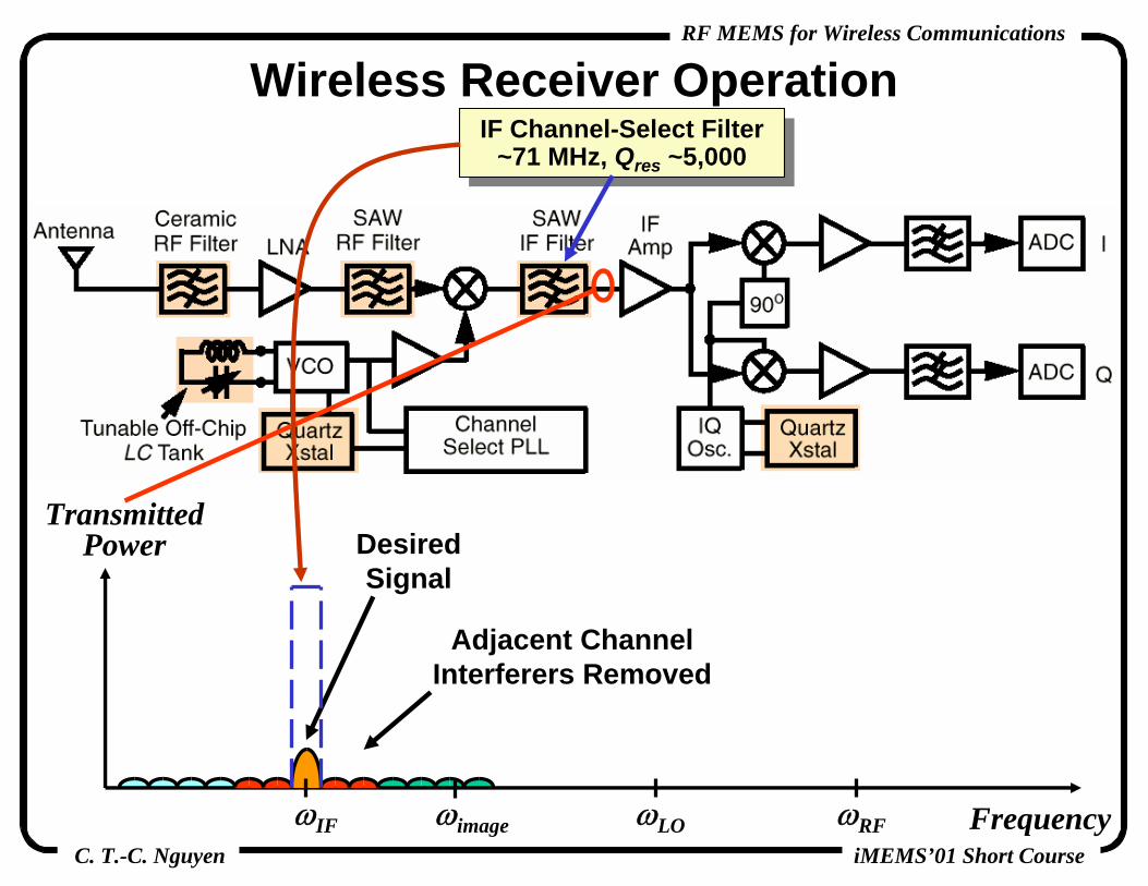
Wireless Receiver Operation
TransmittedPower
FrequencyωRFωLOωIF
DesiredSignal
IF Channel-Select Filter~71 MHz, Qres ~5,000
IF Channel-Select Filter~71 MHz, Qres ~5,000
Signals Mixed Down to IF[Reason: easier (i.e., cheaper) to
select at low freq.]
ωimage
C. T.-C. Nguyen
RF MEMS for Wireless Communications
iMEMS’01 Short Course
Wireless Receiver Operation
TransmittedPower
FrequencyωRFωLOωIF
DesiredSignal
IF Channel-Select Filter~71 MHz, Qres ~5,000
IF Channel-Select Filter~71 MHz, Qres ~5,000
Adjacent ChannelInterferers Removed
ωimage

C. T.-C. Nguyen
RF MEMS for Wireless Communications
iMEMS’01 Short Course
Wireless Receiver Operation
TransmittedPower
FrequencyωRFωLOωIF
DesiredSignal
IQ Mixer~71 MHz
IQ Mixer~71 MHz
ωimage

C. T.-C. Nguyen
RF MEMS for Wireless Communications
iMEMS’01 Short Course
Wireless Receiver Operation
TransmittedPower
FrequencyωRFωLOωIF
DesiredSignal
IQ Mixer~71 MHz
IQ Mixer~71 MHz
Signals translated in demodulation
process by IQ mixer
ωimage

C. T.-C. Nguyen
RF MEMS for Wireless Communications
iMEMS’01 Short Course
Outline• Miniaturization of Transceivers
the need for high-Q• Receiver Design and Operation• Oscillator Fundamentals and Needs• Medium-Q Tunable μMech. Capacitors• Medium-Q Micromachined Inductors• High-Q Micromechanical Resonators• High-Q Micromechanical Filters• Micromechanical Mixer-Filters• Micromechanical Switches• Integration Technologies• Power Savings Via High-Q MEMS• Conclusions
Κ

C. T.-C. Nguyen
RF MEMS for Wireless Communications
iMEMS’01 Short Course
• Below: synthesizers indicated in yellow
• Need: oscillators with adequate frequency stability
Synthesizer Oscillators Within Transceivers
Down-ConvertingLocal Oscillator
Synthesizer~874 MHz
Down-ConvertingLocal Oscillator
Synthesizer~874 MHz
Up-ConvertingLocal Oscillator
Synthesizer~831 MHz
Up-ConvertingLocal Oscillator
Synthesizer~831 MHz
IQ Oscillator~71 MHz
IQ Oscillator~71 MHz

C. T.-C. Nguyen
RF MEMS for Wireless Communications
iMEMS’01 Short Course
Communications Oscillator• Main Function: provide a stable output frequency• Difficulty: superposed noise degrades frequency stability
ωωο
ivoi
A
Frequency-SelectiveTank
SustainingAmplifier
ov
Ideal Sinusoid: ( ) ⎟⎠⎞⎜
⎝⎛= tofVotov π2sin
Real Sinusoid: ( ) ( ) ( )⎟⎠⎞⎜
⎝⎛⎟
⎠⎞⎜
⎝⎛ ++= ttoftVotov θπε 2sin
ωωο
ωωο=2π/TO
TO
Zero-Crossing Point
Higher QHigher QTighter SpectrumTighter Spectrum

C. T.-C. Nguyen
RF MEMS for Wireless Communications
iMEMS’01 Short Course
An Ideal Receiver

C. T.-C. Nguyen
RF MEMS for Wireless Communications
iMEMS’01 Short Course
Impact of Phase Noise on Receivers• Local oscillator phase noise can mask desired
information signals after mixing

C. T.-C. Nguyen
RF MEMS for Wireless Communications
iMEMS’01 Short Course
Plotting Phase Noise• Phase Noise = (1/2) x total output noise (other 1/2 is
amplitude noise, which can be removed by limiting)• Plot phase noise-to-carrier power ratio against offset
from the carrier on log scales
Carrier = { }oo ff
vCΔ
=2
{ } { }mo
mop ff
vfNΔ
=2
21
fo+fm
Plot RHS
opNC
1/f3 NoiseCaused By
Aliased 1/f Noise
1/f3 NoiseCaused By
Aliased 1/f Noise
1/f2 NoiseCaused By White Electronic Noise
1/f2 NoiseCaused By White Electronic Noise
White NoiseFrom Next Stage
White NoiseFrom Next Stage

C. T.-C. Nguyen
RF MEMS for Wireless Communications
iMEMS’01 Short Course
Phase Noise in Specific OscillatorsHigh-Q Oscillators
• Tank Q ~ tens of thousands• Example: crystal oscillator
• {fm=1kHz} = -140dBc/Hz• Adv.: extremely stable• Disadv.: large size; requires
off-chip component
Low- to Medium-Q Oscillators• Tank Q ~ less than 30• Example: LC or ring osc.
• {fm=600kHz} = -100dBc/Hz• Adv.: high frequency, large
tuning range (good VCO’s)• Disadv.: poor close-to-carrier
stabilityNeed: high-Q in small size
10MHz
800MHz

C. T.-C. Nguyen
RF MEMS for Wireless Communications
iMEMS’01 Short Course
• Below: synthesizers indicated in yellow
• Need: oscillators with adequate frequency stability
Synthesizer Oscillators Within Transceivers
Down-ConvertingLocal Oscillator
Synthesizer~874 MHz
Down-ConvertingLocal Oscillator
Synthesizer~874 MHz
Up-ConvertingLocal Oscillator
Synthesizer~831 MHz
Up-ConvertingLocal Oscillator
Synthesizer~831 MHz
IQ Oscillator~71 MHz
IQ Oscillator~71 MHz

C. T.-C. Nguyen
RF MEMS for Wireless Communications
iMEMS’01 Short Course
Today’s Local Oscillator Synthesizer
• Phase locking cleans up the VCO output spectrum
• Result: sufficiently stable, tunable oscillator

C. T.-C. Nguyen
RF MEMS for Wireless Communications
iMEMS’01 Short Course
Voltage-Controlled OscillatorsOff-Chip Implementation
• Off-chip inductor Q ~ 100’s• Tunable varactor diode
capacitor Q ~ 60
On-Chip Implementation
• Spiral (shown) or bond-wire inductor Q: 3 to 20
• Tunable reverse-biased diode capacitor high series R
• Problem: capacitor lacks Qand tuning range

C. T.-C. Nguyen
RF MEMS for Wireless Communications
iMEMS’01 Short Course
Outline• Miniaturization of Transceivers
the need for high-Q• Receiver Design and Operation• Oscillator Fundamentals and Needs• Medium-Q Tunable μMech. Capacitors• Medium-Q Micromachined Inductors• High-Q Micromechanical Resonators• High-Q Micromechanical Filters• Micromechanical Mixer-Filters• Micromechanical Switches• Integration Technologies• Power Savings Via High-Q MEMS• Conclusions
Κ

C. T.-C. Nguyen
RF MEMS for Wireless Communications
iMEMS’01 Short Course
Voltage-Tunable High-Q Capacitor• Micromachined, movable, metal plate-to-plate capacitors• Tuning range exceeding that of on-chip diode capacitors and
on par with off-chip varactor diode capacitors
• Challenges: microphonics, tuning range truncated by pull-in
Ground PlanePrevents Pull-Inof Suspensions
Ground PlanePrevents Pull-Inof Suspensions

C. T.-C. Nguyen
RF MEMS for Wireless Communications
iMEMS’01 Short Course
Governing Displacement Equations• Two forces at work
electrostatic force:
mechanical restoring force:
• Expression relating Va and dequate forces: Fa = Fm
222
21
21
dAV
xCV
xEF o
aaaε
=∂∂
=∂∂
=
( )ddkF om −=
( )dddAkV o
oa −= 22
ε
Plat
e H
eigh
t, d
Actuation Voltage, Va
do
(2/3)do
Va Fa d Fa(+) feedback instability
and ultimately pull-in
Pull-InVoltage, VPI
PlateOverlap
Area
( ) ( )a
oa Vd
AVC ε=
Initial GapSpacing, do

C. T.-C. Nguyen
RF MEMS for Wireless Communications
iMEMS’01 Short Course
Fabricated Voltage-Tunable High-Q Capacitor• Surface micromachined in sputtered aluminum
• Ctot = 2.2pF; 16% tuning range for ΔVtune=5.5V; Q=60• Challenge: contact and support line resistance degrades Q

C. T.-C. Nguyen
RF MEMS for Wireless Communications
iMEMS’01 Short Course
Enhancing the Tuning Range• Tuning range limited by pull-in caused by (+) feedback
in the force, charge, displacement sytemPull-In Voltage, VPI:
• Possible Solutions:use leveraged bending [Hung, Senturia JMEMS’99]alternative actuation methods (non-electrostatic)
electro-thermal actuators provide much wider tunng range; problem: power consumption [Harsh, Lee 1999]
use a series capacitor to add (-) feedback that counteracts the (+) feedback, making the system more stable [Seeger, Crary 1997]
AkdVV
o
oddaPI o ε278 3
32 == = Gap Spacing
Plate OverlapArea
SuspensionStiffness

C. T.-C. Nguyen
RF MEMS for Wireless Communications
iMEMS’01 Short Course
Va
Advantages:• Rigidly-anchored top and bottom plates
no need for long suspension beamslarger contacts lower Rs high Q
• Tuning range set by ratio of dielectric slab thickness to capacitive gap can be large
• No possibility for top to bottom plate shorting
Bottom Plate
MovableDielectric
F Va
Fixed Top PlateSpring
cf.
Tunable-Dielectric μMechanical Capacitor
Cross-Sectional View
Comb-TypeTop View

C. T.-C. Nguyen
RF MEMS for Wireless Communications
iMEMS’01 Short Course
Governing Equation for Tunable-Dielectric Micromechanical Capacitance
• Approximate formulation: (neglecting fringing fields)
C1
Cd
C2
C0
L
t0
td
x
kF
Vaεd εa
insensitive to vertical motion of the dielectric
:
( )( )
( )
) (if
00
000
210
add
da
a
ddda
daa
dtot
xtt
tLt
xtttt
L
seriesCseriesCCCC
εεε
εεεε
εεε
>>⎟⎟⎠
⎞⎜⎜⎝
⎛−
+=
⎥⎦
⎤⎢⎣
⎡−
+−+=
+=
(or metal slab)
d
a
ttx
−0
ε
C. T.-C. Nguyen
RF MEMS for Wireless Communications
iMEMS’01 Short Course
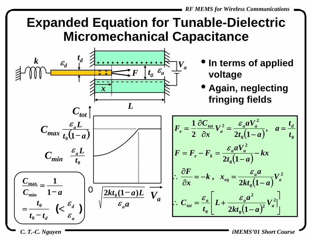
Expanded Equation for Tunable-Dielectric Micromechanical Capacitance
• In terms of applied voltage
• Again, neglecting fringing fields
L
t0
td
x
kF
Vaεd εa
( )
( )
( )
( ) ⎥⎦
⎤⎢⎣
⎡
−+=∴
−=−=
∂∂
∴
−−
=−=
=−
=∂∂
=
22
0
2
0
2
0
0
2
00
22
12
12 ,
12
,122
1
aaa
tot
aa
eq
aake
daaa
tote
Vakt
aLt
C
Vakt
axkxF
kxat
aVFFF
tta
ataVV
xCF
εε
ε
ε
ε
0
atL
0
ε
( )atLa
−10
ε
aLakt
aε)1(2 0 −
Ctot
Va
Cmax
Cmin
min
max
11
aCC
−=
=d− tt0
t0 (< )aεdε

C. T.-C. Nguyen
RF MEMS for Wireless Communications
iMEMS’01 Short Course
Bottom Plate
Top Electrode
Dielectric
To Anchor
Lateral Sprin
g
To anchor without any spring
L l
tl
wl
3μm
7μm
8μm
5μm
100μm
• Waffle-shaped top electrodesallow smaller travel distance for a given capacitance changeprovides etchant access paths during fabrication
• Flat bottom plateeliminates surface topography
( )
EtLw
n
VaLt
ak
ll
l
aa
×⎟⎟⎠
⎞⎜⎜⎝
⎛×=
−=
3
2
0
1
12ε
n=3 for the case above
Tunable-Dielectric Capacitor Design

C. T.-C. Nguyen
RF MEMS for Wireless Communications
iMEMS’01 Short Course
Tunable-Dielectric Capacitor Fabrication
PISi wafer
DielectricCr/Cu Seed
Plated Cu (5μm)Plated Ni (0.3μm)
PI
1st Sacrificial Al (0.2μm)PECVD SiNx (0.6μm)
PI
2nd Sacrificial Al (0.9μm)
(1)
(2)
(3) Bottom Cu

C. T.-C. Nguyen
RF MEMS for Wireless Communications
iMEMS’01 Short Course
(4)
(5)
PI
Thick Photoresist (10μm)
Plated Cu (7μm)
Cr/Cu Seed
Movable Dielectric (Anchor Not Shown)
All process temperatures < 200 ºCamenable to post-IC integration
Si wafer
Bottom Cu
Top CuCritical point drying for anti-stiction
Tunable-Dielectric Capacitor Fabrication

C. T.-C. Nguyen
RF MEMS for Wireless Communications
iMEMS’01 Short Course
Bent-Up PECVD SiNxLateral Spring Cu Bottom GND
Waffle-Shaped Cu Top Electrode
GSG Pads
Fabricated Tunable-Dielectric Capacitor
[Yoon et al, IEDM’00]
• Waffle-shaped top electrodesallow smaller travel distance for a given cap. changeprovides etchant access paths during fabrication
• Flat bottom plateeliminates surface topography 0 1 2 3 4 5 6
1.0
1.1
1.2
1.3
1.4
1.5
0
100
200
300
400
500
Frequency (GHz)
C(p
F)
Q-factor
(Line: measured, Symbol: modeled)
Q
C
Model0.4472Ω 0.05283nH
1.2047pF
0V BiasLateral Spring
(a)
RF Performance:C = 1.21pF @ 0VQ = 291 @ 1GHz
SRF = 19GHz7.7% tuning over 10V

C. T.-C. Nguyen
RF MEMS for Wireless Communications
iMEMS’01 Short Course
Outline• Miniaturization of Transceivers
the need for high-Q• Receiver Design and Operation• Oscillator Fundamentals and Needs• Medium-Q Tunable μMech. Capacitors• Medium-Q Micromachined Inductors• High-Q Micromechanical Resonators• High-Q Micromechanical Filters• Micromechanical Mixer-Filters• Micromechanical Switches• Integration Technologies• Power Savings Via High-Q MEMS• Conclusions
Κ

C. T.-C. Nguyen
RF MEMS for Wireless Communications
iMEMS’01 Short Course
Spiral Inductor Deficiences
• Series Rs degrades Qsolns: increase L per unit length; use thicker metal
• Parasitic Co, Cox, Csub, and Rsub self-resonance, degrades Qsoln: isolate from substrate
C. T.-C. Nguyen
RF MEMS for Wireless Communications
iMEMS’01 Short Course
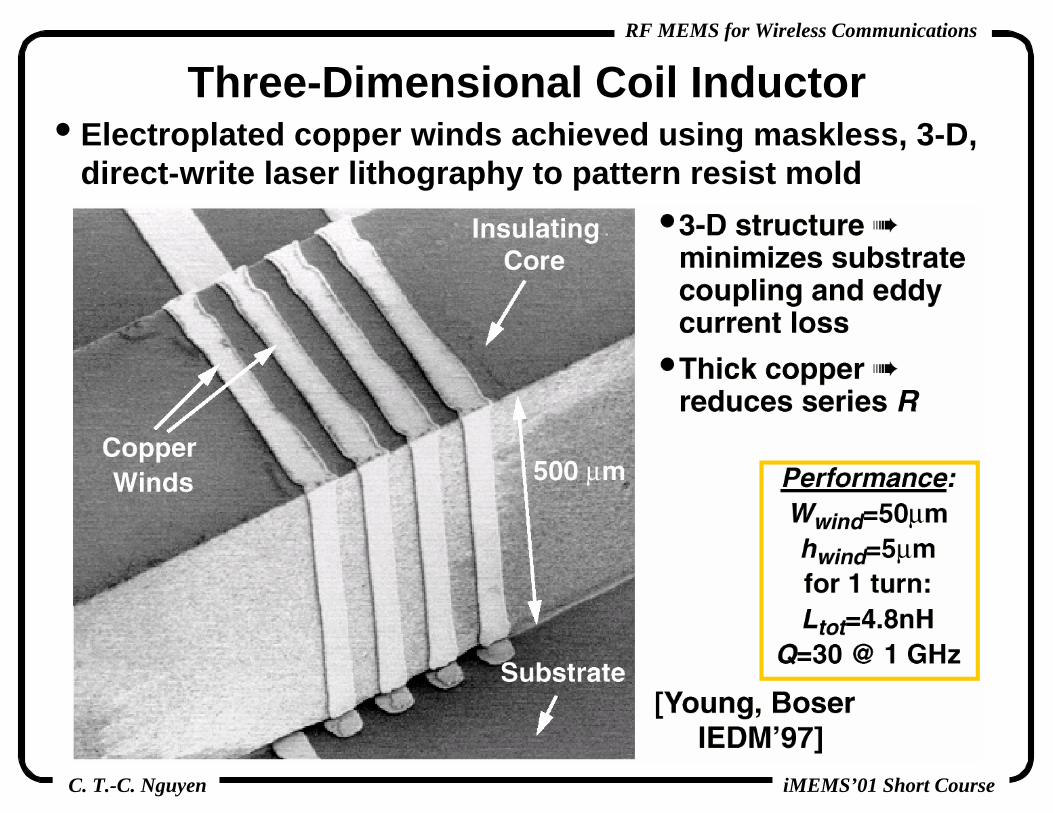
Three-Dimensional Coil Inductor• Electroplated copper winds achieved using maskless, 3-D,
direct-write laser lithography to pattern resist mold

C. T.-C. Nguyen
RF MEMS for Wireless Communications
iMEMS’01 Short Course
Suspended, Stacked Spiral Inductor• Strategies for maximizing Q:
15μm-thick, electroplated Cu windings reduces series Rsuspended above the substrate reduces substrate loss

C. T.-C. Nguyen
RF MEMS for Wireless Communications
iMEMS’01 Short Course
Self-Assembling Variable Inductors • Use interlayer stress to warp released inductors to
significantly elevate them above the substrate• Well-isolated from
substrate minimizes substrate currents and eddy current loss
• Hinged anchors reduce temperature dependence
• Challenge: microphonics
Design/Performance:(with 0.5μm Cr-Au turns
on 1 Ω-cm substrate)L = 1nH, Q =13 @ 7GHz
SRF = 15GHz
[Lubecke, Gammel 2000]
Hinges

C. T.-C. Nguyen
RF MEMS for Wireless Communications
iMEMS’01 Short Course
On-Chip Tunable High-Q LC Bandpass Filter
• Desired for implementing a tunable RF pre-select filter for multi-band reconfigurability; i.e., allowing a single phone to communicate in several standards, such as GSM, DCS1800, PCS, etc.
• Need: micro-scale inductors and tunable capacitors with Q’s >300 (topic for ongoing research)
Micromachined Inductor, Q ~300
Need: major Q increase
Micromachined Inductor, Q ~300
Need: major Q increase
Micromachined Tunable Capacitors
Q ~300
Micromachined Tunable Capacitors
Q ~300[Yao 1997]

C. T.-C. Nguyen
RF MEMS for Wireless Communications
iMEMS’01 Short Course
Components Realizable By Micromachined L and C Technology
• VCO Tank: for best on-chip performance• Tunable Bias/Matching Networks: save power in amplifiers• RF Multi-Band Pre-Select Filter: only if QL ~300 is possible
RF Pre-Select Filterfo~945MHz, BW~40MHz
Adv.: small size, tunableChallenge: QL~300
RF Pre-Select Filterfo~945MHz, BW~40MHz
Adv.: small size, tunableChallenge: QL~300
Bias/Matching Tanksfo~945MHz, 902MHzAdv.: lower power
Bias/Matching Tanksfo~945MHz, 902MHzAdv.: lower power
VCO Tanksfo~874MHz,71MHz, 831MHz
Adv.: lower power
VCO Tanksfo~874MHz,71MHz, 831MHz
Adv.: lower power

C. T.-C. Nguyen
RF MEMS for Wireless Communications
iMEMS’01 Short Course
Today’s Local Oscillator Synthesizer
• Phase locking cleans up the VCO output spectrum
• Result: sufficiently stable, tunable oscillator

C. T.-C. Nguyen
RF MEMS for Wireless Communications
iMEMS’01 Short Course
• Yellow: replaceable LC tanks (low- to medium-Q required)• Red: very high-Q tanks required (Q >1,000)
High-Q Transceiver Components
RF Pre-Select Filter~945 MHz, Qres ~500RF Pre-Select Filter~945 MHz, Qres ~500
RF Image-Reject Filter~945 MHz, Qres ~1,000
RF Image-Reject Filter~945 MHz, Qres ~1,000 IF Channel-Select Filter
~71 MHz, Qres ~5,000IF Channel-Select Filter
~71 MHz, Qres ~5,000
High-Q ReferenceTank, Qres ~20,000
High-Q ReferenceTank, Qres ~20,000
High-Q ReferenceTank, Qres ~20,000
High-Q ReferenceTank, Qres ~20,000

C. T.-C. Nguyen
RF MEMS for Wireless Communications
iMEMS’01 Short Course
Outline• Miniaturization of Transceivers
the need for high-Q• Receiver Design and Operation• Oscillator Fundamentals and Needs• Medium-Q Tunable μMech. Capacitors• Medium-Q Micromachined Inductors• High-Q Micromechanical Resonators• High-Q Micromechanical Filters• Micromechanical Mixer-Filters• Micromechanical Switches• Integration Technologies• Power Savings Via High-Q MEMS• Conclusions
Κ

C. T.-C. Nguyen
RF MEMS for Wireless Communications
iMEMS’01 Short Course
Micromechanical Resonator History• Very first μmechanical resonators: Nathanson et al (1967)
metal structural materialresonant-beam serves as gate for NMOS transistorProblems: surface charge, high TCf, frequency drift, Q~90
• First polysilicon-based resonator combined with NMOS technology by Howe et al (1984)
C. T.-C. Nguyen
RF MEMS for Wireless Communications
iMEMS’01 Short Course
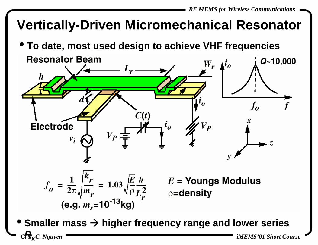
Vertically-Driven Micromechanical Resonator• To date, most used design to achieve VHF frequencies
• Smaller mass higher frequency range and lower series Rx

C. T.-C. Nguyen
RF MEMS for Wireless Communications
iMEMS’01 Short Course
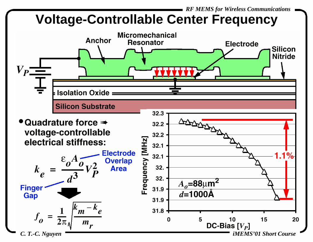
Voltage-Controllable Center Frequency

C. T.-C. Nguyen
RF MEMS for Wireless Communications
iMEMS’01 Short Course
Micromechanical Resonator Equivalent Circuit

C. T.-C. Nguyen
RF MEMS for Wireless Communications
iMEMS’01 Short Course
Fabricated HF μMechanical Resonator• Surface-micromachined, POCl3-doped polycrystalline silicon
• Extracted Q = 8,000 (vacuum)• Freq. influenced by dc-bias
and anchor effects

C. T.-C. Nguyen
RF MEMS for Wireless Communications
iMEMS’01 Short Course
Off-Chip 10MHz Pierce Oscillator• Buffer stage added to the classic
Pierce to preserve 0o loop phase shift despite a large Rx ~ 2 kΩ
Vo: ~ 210 mV
TransconductanceStage
BufferStage
Oscilloscope Waveform
Fourier Spectrum
[Lee, Demirci,Nguyen,Trans’01]
Confidential: Not to be released without the expressed written permission of Prof. Clark T.-C. Nguyen and the NSF ERC on WIMS.
C. T.-C. Nguyen
RF MEMS for Wireless Communications
iMEMS’01 Short Course
Outline• Miniaturization of Transceivers
the need for high-Q• Receiver Design and Operation• Oscillator Fundamentals and Needs• Medium-Q Tunable μMech. Capacitors• Medium-Q Micromachined Inductors• High-Q Micromechanical Resonators• High-Q Micromechanical Filters• Micromechanical Mixer-Filters• Micromechanical Switches• Integration Technologies• Power Savings Via High-Q MEMS• Conclusions
Κ

C. T.-C. Nguyen
RF MEMS for Wireless Communications
iMEMS’01 Short Course
Fabricated HF μMechanical Resonator• Surface-micromachined, POCl3-doped polycrystalline silicon
• Extracted Q = 8,000 (vacuum)• Freq. influenced by dc-bias
and anchor effects

C. T.-C. Nguyen
RF MEMS for Wireless Communications
iMEMS’01 Short Course
Desired Filter Characteristics
• Small shape factor generally preferred

C. T.-C. Nguyen
RF MEMS for Wireless Communications
iMEMS’01 Short Course
Micromechanical Circuits• A single mechanical beam can’t really do much on its own• But use many mechanical beams attached together in a
circuit, and attain a more complex, more useful function
InputForce
Fi
OutputDisplacement
xo
t
xo
t
Fi
Key Design Property: High Q

C. T.-C. Nguyen
RF MEMS for Wireless Communications
iMEMS’01 Short Course
Desired Filter Characteristics
• Small shape factor generally preferred

C. T.-C. Nguyen
RF MEMS for Wireless Communications
iMEMS’01 Short Course
Micromechanical Filter Circuit

C. T.-C. Nguyen
RF MEMS for Wireless Communications
iMEMS’01 Short Course
Ideal Spring-Coupled μMechanical Filter
ks12mr1
kr1
cr1
kr2
mr2
cr2
Symmetric Mode Anti-Symmetric Mode
BW ~ ks12
kr

C. T.-C. Nguyen
RF MEMS for Wireless Communications
iMEMS’01 Short Course
Micromechanical Filter Circuit
C. T.-C. Nguyen
RF MEMS for Wireless Communications
iMEMS’01 Short Course
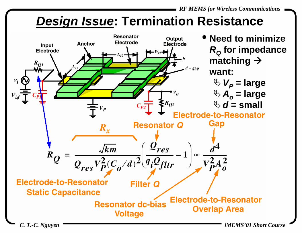
Design Issue: Termination Resistance• Need to minimize
RQ for impedance matching want:
VP = largeAo = larged = small

C. T.-C. Nguyen
RF MEMS for Wireless Communications
iMEMS’01 Short Course
Small Electrode-to-Resonator Gaps

C. T.-C. Nguyen
RF MEMS for Wireless Communications
iMEMS’01 Short Course
HF Spring-Coupled Micromechanical Filter

C. T.-C. Nguyen
RF MEMS for Wireless Communications
iMEMS’01 Short Course
Attaining Better Performance• Use more resonators to attain higher order• Filter Order = 2 x (# of resonators)
• Higher Order sharper roll-off better stopband rejection

C. T.-C. Nguyen
RF MEMS for Wireless Communications
iMEMS’01 Short Course
High-Order μMechanical Filter

C. T.-C. Nguyen
RF MEMS for Wireless Communications
iMEMS’01 Short Course
Design Issue: Process Tolerances
• Process variations can lead to distortion in the filter passband

C. T.-C. Nguyen
RF MEMS for Wireless Communications
iMEMS’01 Short Course
Electrostatic Frequency Tuning• Use nonlinear parallel-plate transducers for electrostatic
frequency tuning

C. T.-C. Nguyen
RF MEMS for Wireless Communications
iMEMS’01 Short Course
μMechanical Filter Passband Correction
• Problems: too many interconnect leads, Δf small at VHF• Need: a permanent frequency trimming technique
[Wang,Nguyen,1997]

C. T.-C. Nguyen
RF MEMS for Wireless Communications
iMEMS’01 Short Course
Micromechanical Filter Video
C. T.-C. Nguyen
RF MEMS for Wireless Communications
iMEMS’01 Short Course
Outline• Miniaturization of Transceivers
the need for high-Q• Receiver Design and Operation• Oscillator Fundamentals and Needs• Medium-Q Tunable μMech. Capacitors• Medium-Q Micromachined Inductors• High-Q Micromechanical Resonators• High-Q Micromechanical Filters• Micromechanical Mixer-Filters• Micromechanical Switches• Integration Technologies• Power Savings Via High-Q MEMS• Conclusions
Κ

C. T.-C. Nguyen
RF MEMS for Wireless Communications
iMEMS’01 Short Course
Capacitive Transducer
IFω ω
ElectricalSignal Input
MechanicalSignal Input
ωωIF
FilterResponse
ωo=ωIF

C. T.-C. Nguyen
RF MEMS for Wireless Communications
iMEMS’01 Short Course
ElectricalSignal Input
MechanicalSignal Input
ωRFωLO
ωRFωLOωIF
ω
ω
FilterResponse
Electromechanical Mixing
ωIF
ωo=ωIF

C. T.-C. Nguyen
RF MEMS for Wireless Communications
iMEMS’01 Short Course
Micromechanical Mixer-Filter
[Wong, Nguyen 1998]

C. T.-C. Nguyen
RF MEMS for Wireless Communications
iMEMS’01 Short Course
• Main Requirements:frequency extension for LPCVD deviceshigher Q for FBARs
Components Realizable By Vibrating MEMSIF Channel-Select Mixer-
Filter-Gain Stagefo~71MHz, BW~200kHz
Adv.: tiny, lower I.L., 0 W
IF Channel-Select Mixer-Filter-Gain Stage
fo~71MHz, BW~200kHzAdv.: tiny, lower I.L., 0 W
RF Pre-Select Filterfo~945MHz BW~40MHz
Adv.: tiny, lower I.L.FBAR: now
LPCVD: freq. ext.
RF Pre-Select Filterfo~945MHz BW~40MHz
Adv.: tiny, lower I.L.FBAR: now
LPCVD: freq. ext.
RF Image-Rej. Filterfo~945MHzBW~25MHz
Adv.: tiny, lower I.L.FBAR: now
LPCVD: freq. ext.
RF Image-Rej. Filterfo~945MHzBW~25MHz
Adv.: tiny, lower I.L.FBAR: now
LPCVD: freq. ext.High-Q TankQ ~10,000Adv.: tiny
High-Q TankQ ~10,000Adv.: tiny

C. T.-C. Nguyen
RF MEMS for Wireless Communications
iMEMS’01 Short Course
Vibrating MEMS Research Issues:Frequency Extension

C. T.-C. Nguyen
RF MEMS for Wireless Communications
iMEMS’01 Short Course
Research Issue: Frequency Extension• To extend the frequency range
shrink beam dimensionsmust shrink gap d dimensions, as well
• Possible Problem: Q reduction with frequencymaterial and anchor loss mechanismssolution: defensive mechanical design, materials engineering

C. T.-C. Nguyen
RF MEMS for Wireless Communications
iMEMS’01 Short Course
Anchor Dissipation in Fixed-Fixed Beams
fo↑Q↓

C. T.-C. Nguyen
RF MEMS for Wireless Communications
iMEMS’01 Short Course
92 MHz Free-Free Beam μResonator• Free-free beam μmechanical resonator with non-intrusive
supports reduce anchor dissipation higher Q

C. T.-C. Nguyen
RF MEMS for Wireless Communications
iMEMS’01 Short Course
92 MHz Free-Free Beam μResonator• Free-free beam μmechanical resonator with non-intrusive
supports reduce anchor dissipation higher Q
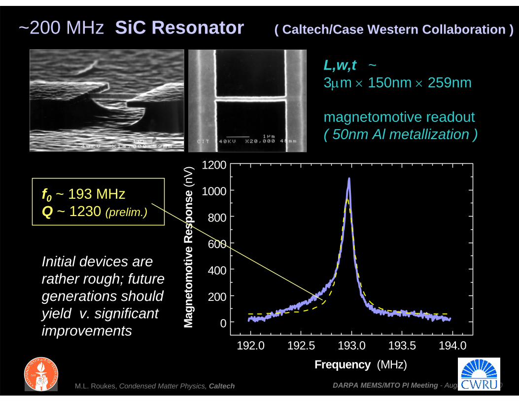
~200 MHz SiC Resonator ( Caltech/Case Western Collaboration )
L,w,t ~ 3μm × 150nm × 259nm
magnetomotive readout( 50nm Al metallization )
192.0 192.5 193.0 193.5 194.0
0
200
400
600
800
1000
1200
Mag
neto
mot
ive
Resp
onse
(nV)
Frequency (MHz)
f0 ~ 193 MHzQ ~ 1230 (prelim.)
Initial devices are rather rough; future generations should yield v. significant improvements
M.L. Roukes, Condensed Matter Physics, Caltech DARPA MEMS/MTO PI Meeting - August 2000 90

C. T.-C. Nguyen
RF MEMS for Wireless Communications
iMEMS’01 Short Course
Research Issue: Frequency Extension• To extend the frequency range
shrink beam dimensionsmust shrink gap d dimensions, as well
• Possible Problem: Q reduction with frequencymaterial and anchor loss mechanismssolution: defensive mechanical design, materials engineering
• Possible Problem: size vs. power handling trade-offsmay limit the degree of size reduction allowablesolution: transducer design, other vibration modes

C. T.-C. Nguyen
RF MEMS for Wireless Communications
iMEMS’01 Short Course
156 MHz Radial Contour-Mode Disk μMechanical Resonator
• Below: Balanced radial-mode disk polysilicon μmechanicalresonator (34 μm diameter)
μmechanical DiskResonator
MetalElectrode
MetalElectrode
R
Anchor
Design/Performance:R=17μm, t=2μm
d=1,000Å, VP=35Vfo=156.23MHz, Q=9,400
[Clark, Hsu, Nguyen IEDM’00]
fo=156MHzQ=9,400

C. T.-C. Nguyen
RF MEMS for Wireless Communications
iMEMS’01 Short Course
Structural Polysilicon
μMechanical Disk Resonator Fabrication
Substrate
SiO2Groundplane and Electrode Polysilicon
AnchorGroundplane and Electrode Polysilicon
Si3N4
Sacrificial Oxide Spacer

C. T.-C. Nguyen
RF MEMS for Wireless Communications
iMEMS’01 Short Course
Structural Polysilicon
Substrate
SiO2Groundplane and Electrode Polysilicon
AnchorGroundplane and Electrode Polysilicon
Si3N4
μMechanical Disk Resonator Fabrication

C. T.-C. Nguyen
RF MEMS for Wireless Communications
iMEMS’01 Short Course
Structural Polysilicon
Substrate
SiO2Groundplane and Electrode Polysilicon
AnchorGroundplane and Electrode Polysilicon
Si3N4
Plated Metal Electrodes
μMechanical Disk Resonator Fabrication

C. T.-C. Nguyen
RF MEMS for Wireless Communications
iMEMS’01 Short Course
Structural Polysilicon
Substrate
SiO2Groundplane and Electrode Polysilicon
AnchorGroundplane and Electrode Polysilicon
Si3N4
Plated Metal Electrodes
μMechanical Disk Resonator Fabrication

C. T.-C. Nguyen
RF MEMS for Wireless Communications
iMEMS’01 Short Course
Structural Polysilicon
Substrate
SiO2Groundplane and Electrode Polysilicon
AnchorGroundplane and Electrode Polysilicon
Si3N4
Plated Metal Electrodes
Air Gap d = 1000 Å
μMechanical Disk Resonator Fabrication

C. T.-C. Nguyen
RF MEMS for Wireless Communications
iMEMS’01 Short Course
1000Å Lateral Electrode-to-Disk Gaps• Achieved via a fabrication process that combines
polysilicon surface micromachining, metal electroplating, and sidwall spacer technologies
μMechanicalDisk
Resonator
MetalElectrode
MetalElectrode
2 μm
1,000Å
[Clark, Hsu, Nguyen IEDM’00]

C. T.-C. Nguyen
RF MEMS for Wireless Communications
iMEMS’01 Short Course
Thin-Film Bulk Acoustic Resonator (FBAR)• Piezoelectric membrane sandwiched by metal electrodes
extensional mode vibration: 1.8 to 7 GHz, Q ~1,000dimensions on the order of 200μm for 1.6 GHz
• Link together in ladder networks to make filters

C. T.-C. Nguyen
RF MEMS for Wireless Communications
iMEMS’01 Short Course
Vibrating MEMS Research Issues:Temperature Stability
C. T.-C. Nguyen
RF MEMS for Wireless Communications
iMEMS’01 Short Course
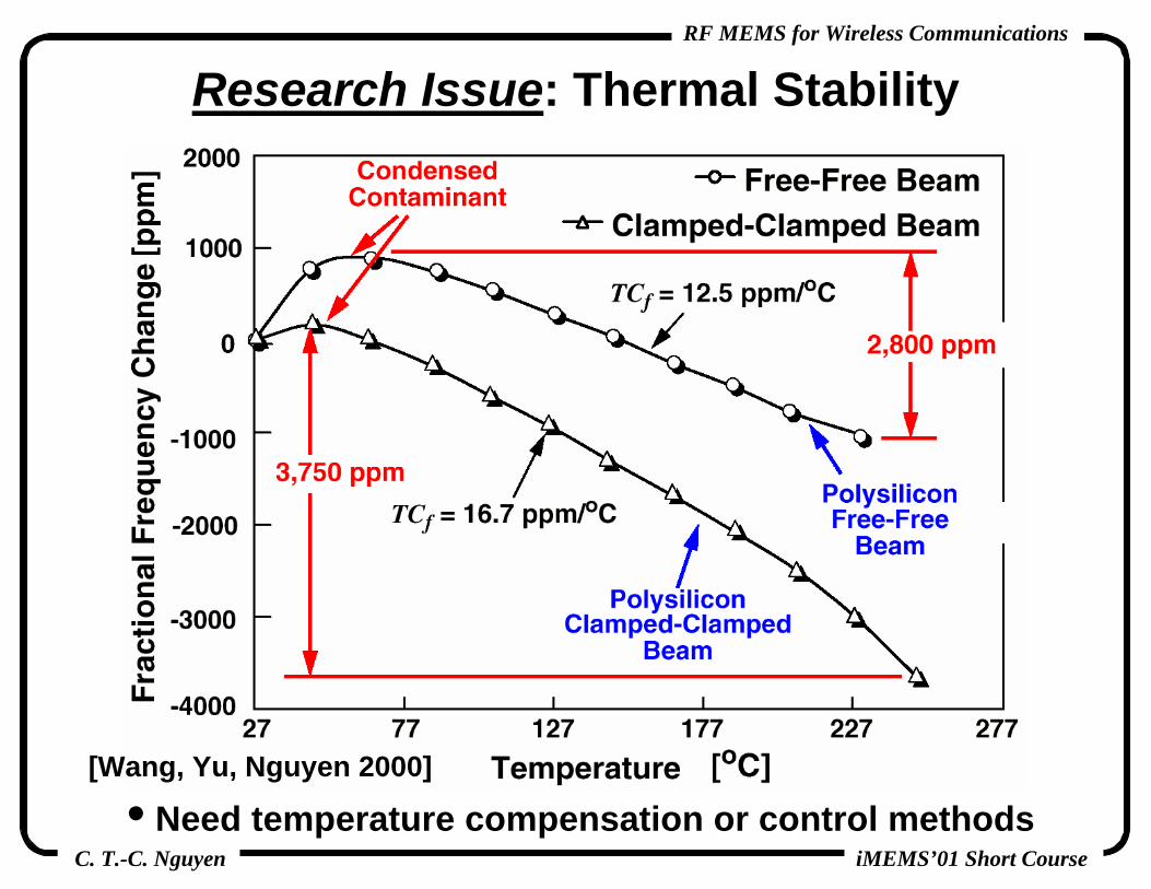
Research Issue: Thermal Stability
• Need temperature compensation or control methods[Wang, Yu, Nguyen 2000]

C. T.-C. Nguyen
RF MEMS for Wireless Communications
iMEMS’01 Short Course
Geometric-Stress Temperature Compensation• Geometrically generate a stress vs. temperature function
that compensates Young’s modulus thermal variation
L1 ≠ L2

C. T.-C. Nguyen
RF MEMS for Wireless Communications
iMEMS’01 Short Course
Fabricated Temp.-Insensitive μResonator
Design/Performance:L1=39μm, L2=39μm, d =1038ÅW1=2.5μm, W2=20μm, t =2μm
VP=16V, fo=13.49MHz, Q=10,317
[Hsu, Clark,Nguyen IEDM’00]

C. T.-C. Nguyen
RF MEMS for Wireless Communications
iMEMS’01 Short Course
• Below: polysilicon structure, silicon substrate
• Less than 200 ppm fo variation over 80oC for L2/L1=60/40
Demonstration of Geometric-Stress Temperature Compensation
[Hsu, Clark, Nguyen 2000]

C. T.-C. Nguyen
RF MEMS for Wireless Communications
iMEMS’01 Short Course
Research Issue: Thermal Stability
• Need temperature compensation or control methods[Wang, Yu, Nguyen 2000]

C. T.-C. Nguyen
RF MEMS for Wireless Communications
iMEMS’01 Short Course
• Contamination fluctuations fo and Q fluctuations
• Factors influencing contamination-derived instabilitiescontaminant molecule size and weightpressure and temperature
• Need encapsulation for contamination protection
Research Issue: Contamination Sensitivity
• Typical μresonatormass: 10-13 kg
• Larger frequency fluctuations for micro-sized resonators than for more massive quartz crystals

C. T.-C. Nguyen
RF MEMS for Wireless Communications
iMEMS’01 Short Course
Planar Processed Vacuum Encapsulation• After surface micromachining, continue
depositing/patterning films to achieve a vacuum cap• Below: the permeable polysilicon method [Lebouitz 1999]
[Lebouitz, Pisano 1999]

C. T.-C. Nguyen
RF MEMS for Wireless Communications
iMEMS’01 Short Course
Research Issue: Vacuum Encapsulation• Below: localized heated bonding to seal a vacuum cap
over a released micromechanical resonator
Glass Cap
µHeaterand
AluminumSolder
Vanneal
Schematic of the BondingEncapsulation Procedure
Broken Glass Cap
Microcavity
2000
2250
2500
2750
3000
0 2 4 6 8 10 12Weeks
Q
40 weeks at 25 mTorr
[Cheng, Hsu, Lin, Nguyen, Najafi 2000]

C. T.-C. Nguyen
RF MEMS for Wireless Communications
iMEMS’01 Short Course
Outline• Miniaturization of Transceivers
the need for high-Q• Receiver Design and Operation• Oscillator Fundamentals and Needs• Medium-Q Tunable μMech. Capacitors• Medium-Q Micromachined Inductors• High-Q Micromechanical Resonators• High-Q Micromechanical Filters• Micromechanical Mixer-Filters• Micromechanical Switches• Integration Technologies• Power Savings Via High-Q MEMS• Conclusions
Κ

C. T.-C. Nguyen
RF MEMS for Wireless Communications
iMEMS’01 Short Course
Micromechanical Switch
[C. Goldsmith, 1995]
• Operate the micromechanical beam in an up/down binary fashion
• Performance: I.L.~0.1dB, IIP3 ~ 66dBm (extremely linear)• Issues: switching voltage ~ 50V, switching time: 1-5μs

C. T.-C. Nguyen
RF MEMS for Wireless Communications
iMEMS’01 Short Course
Phased Array Antenna

C. T.-C. Nguyen
RF MEMS for Wireless Communications
iMEMS’01 Short Course
Switchable Medium-Q Filters
• Need: very low loss switches to retain good Qtransistor switches not usable too much Rs
|v2/v1|
FrequencyLCtot determines fo
[Yao 1997]

C. T.-C. Nguyen
RF MEMS for Wireless Communications
iMEMS’01 Short Course
Micromechanical Switch Pros and ConsAdvantages:• Via use of metal material, the contact and spreading
resistance of ohmic FET or p-i-n diode switches are eliminated, significantly reducing resistive losses
• Extremely good linearity: IIP3 ~66dBm• Negligible DC power consumption (for electrostatic
actuation) switching energy ~10 nJProblems/Limitations:• Slow switching speed (τ~5μs) relative to FET switches
(τ~1ps) precludes use in high-speed applications, such as some transmit/receive switching schemes
• Large actuation voltage: Va ~ 50V• Reliability
actual contact between moving parts wear, weldingsoln.: use capacitive switch, if possiblehot switching can limit power handling

C. T.-C. Nguyen
RF MEMS for Wireless Communications
iMEMS’01 Short Course
Hot Switching• Phenomenon where excessive RF power can inadvertently
close an open switch
• AC voltage on the conductor is rectified in the electrical-to-mechanical conversion; DC force pulls down the beam
• Problem: switch can stay down even if RF power is lowered
tVv cc ωcos=RF Signal
xCv
xEF ca ∂
∂=
∂∂
= 2
21
txCV
xCV cc ω2cos
41
41 22
∂∂
+∂∂
=
Resulting Force:
Fa
DC Force

C. T.-C. Nguyen
RF MEMS for Wireless Communications
iMEMS’01 Short Course
Metrics and Design Issues• Cut-Off Frequency Figure of Merit:
frequency where the ratio of off-impedance to on-impedance degrades to unity
GaAs MESFET: fc = 280GHzGaAs p-i-n Diode: fc = 730GHzMetal Membrane Switch: fc > 9000GHz [Yao, Goldsmith 1999]
• On-off impedance ratio versus actuation voltage trade-offfor a large on-off impedance ratio (desired), must increase the electrode-to-beam gapfor a small actuation voltage (desired), must decrease the electrode-to-beam gap
• Hot switching versus actuation voltage trade-off
offonc CR
fπ2
1=
C. T.-C. Nguyen
RF MEMS for Wireless Communications
iMEMS’01 Short Course
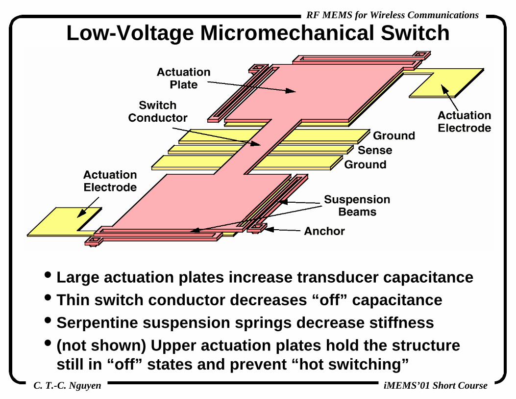
Low-Voltage Micromechanical Switch
• Large actuation plates increase transducer capacitance• Thin switch conductor decreases “off” capacitance• Serpentine suspension springs decrease stiffness• (not shown) Upper actuation plates hold the structure
still in “off” states and prevent “hot switching”

C. T.-C. Nguyen
RF MEMS for Wireless Communications
iMEMS’01 Short Course
• Electroplated Ni material; problems with warping• With four meanders in the supporting springs: Vswitch= 9V
Fabricated Low-Voltage μMechanical Switch
[Pacheco,Katehi,
Nguyen 2000]

C. T.-C. Nguyen
RF MEMS for Wireless Communications
iMEMS’01 Short Course
Components Realizable Via Micromechanical Switch Technology
• RF Pre-Select Filter: if Q ~300 is possible, then this filter could satisfy multi-band requirements
• Antenna & Filter Switching: great performance; switch filters for multi-band reconfigurability
RF Pre-Select Filterfo~945MHzBW~40MHz
Adv.: low lossChallenge: Q ~300
RF Pre-Select Filterfo~945MHzBW~40MHz
Adv.: low lossChallenge: Q ~300
Antenna & Filter SwitchingAdv.: low loss, linearityChallenge: Reliability
Antenna & Filter SwitchingAdv.: low loss, linearityChallenge: Reliability Focus of Much
Research/Development

C. T.-C. Nguyen
RF MEMS for Wireless Communications
iMEMS’01 Short Course
• A large number of off-chip high-Q components replaceable with μmachined versions; e.g., using μmachined resonators, switches, capacitors, and inductors
MEMS-Replaceable Transceiver Components

C. T.-C. Nguyen
RF MEMS for Wireless Communications
iMEMS’01 Short Course
Miniaturization of Transceivers via MEMS
• Off-chip high-Q mechanical components present bottlenecks to miniaturization replace them with μmechanical versions

C. T.-C. Nguyen
RF MEMS for Wireless Communications
iMEMS’01 Short Course
Outline• Miniaturization of Transceivers
the need for high-Q• Receiver Design and Operation• Oscillator Fundamentals and Needs• Medium-Q Tunable μMech. Capacitors• Medium-Q Micromachined Inductors• High-Q Micromechanical Resonators• High-Q Micromechanical Filters• Micromechanical Mixer-Filters• Micromechanical Switches• Integration Technologies• Power Savings Via High-Q MEMS• Conclusions
Κ

C. T.-C. Nguyen
RF MEMS for Wireless Communications
iMEMS’01 Short Course
Merged Circuits/μMechanics Technologies (Process Philosophy)
• Mixed:problem: multiple passivation/protection steps ⇒ large number of masks requiredproblem: custom process for each product
• Pre-Circuits or Post-Circuits:adv.: modularity ⇒ flexibility ⇒ less development timeadv.: low pass./protection complexity ⇒ fewer masks

C. T.-C. Nguyen
RF MEMS for Wireless Communications
iMEMS’01 Short Course
Pre-Circuits Xsistor/μMechanics Integration• Problem: μstructural topography interferes with lithography
difficult to apply photoresist for submicron circuits
• Soln.: build μmechanics in a trench, then planarize before circuit processing [Smith et al, IEDM’95]

C. T.-C. Nguyen
RF MEMS for Wireless Communications
iMEMS’01 Short Course
Pre-Circuits Example: Sandia’s iMEMS• Used to demonstrate functional fully integrated oscillators• Issues:
lithography and etching may be difficult in trench may limit dimensions (not good for RF MEMS)μmechanical material must stand up to IC temperatures (>1000oC) problem for some switch metalsmight be contamination issues for foundry IC’s
[Smith et al, IEDM’95]

C. T.-C. Nguyen
RF MEMS for Wireless Communications
iMEMS’01 Short Course
Post-Circuits Xsistor/μMechanics Integration • Modular technology minimizes product updating effort
Module 1: circuit process (planar IC technology)Module 2: micromachining process (planar technology)
• Adv.: topography after circuit fabrication is much smaller• Problem: limited thermal budget
metal and junctions must withstand temperatures ~835oCtungsten metallization used with TiSi2 contact barriersin situ doped structural polySi; rapid thermal annealing

C. T.-C. Nguyen
RF MEMS for Wireless Communications
iMEMS’01 Short Course
Post-CMOS Circuits/μMechanics Integration• Completely monolithic, low phase noise, high-Q oscillator
(effectively, an integrated crystal oscillator) [Nguyen, Howe]
• To allow the use of >600oC processing temperatures, tungsten (instead of aluminum) is used for metallization
OscilloscopeOutput
Waveform

C. T.-C. Nguyen
RF MEMS for Wireless Communications
iMEMS’01 Short Course
Post-Circuits Xsistor/μMechanics Integration • Problem: tungsten is not an accepted primary interconnect
metal• Challenge: retain conventional metallization
minimize post-CMOS processing temperaturesexplore alternative structural materials (e.g., plated nickel, SiGe [Franke, Howe et al, MEMS’99])

C. T.-C. Nguyen
RF MEMS for Wireless Communications
iMEMS’01 Short Course
Post-Circuits Integration Using Bonding• Bonding technologies can potentially achieve true
modularity in post-CMOS integration, with the greatest flexibility in circuit and μmechanical technologies
• Avantages:modules completey separate; no compromises
virtually any circuit can be combined with virtually any MEMS process
no contamination or compatibility issues for integrated circuit foundriesany mechanical material can be used: polysilicon, aluminum, copper, CVD diamond, SiC
• Challenges: yield vs. bond area (which should be minimized to avoid excessive capacitance)
• Question: high volume production possible?

C. T.-C. Nguyen
RF MEMS for Wireless Communications
iMEMS’01 Short Course
Bonded-Platform Circuits/μMechanicsMerging Process (Bonding)
• Platform micromechanics and circuit wafer merged via compression bonding (completely modular)
Confidential: Not to be released without the expressed written permission of Prof. Clark T.-C. Nguyen and the NSF ERC on WIMS.
SupportingStruts Bend

C. T.-C. Nguyen
RF MEMS for Wireless Communications
iMEMS’01 Short Course
Miniaturization of Transceivers via MEMS
• Off-chip high-Q mechanical components present bottlenecks to miniaturization replace them with μmechanical versions

C. T.-C. Nguyen
RF MEMS for Wireless Communications
iMEMS’01 Short Course
MEMS-Based Receiver Architecture• Most Direct Approach: replace off-chip components (in
orange) with μmechanical versions (in green)
• Obvious Benefit: substantial size reduction
Replace with MEMSL1~0.3dBL1~0.3dB
L1~2dBL1~2dB
NF = 8.8dBNF = 8.8dB
NF = 2.8dBNF = 2.8dB
L3~6dBL3~6dB L5~12dBL5~12dB
L3~0.5dBL3~0.5dB L5~1dBL5~1dB
Antenna Diversity for
resilience against fading
Antenna Diversity for
resilience against fading
Higher Q

C. T.-C. Nguyen
RF MEMS for Wireless Communications
iMEMS’01 Short Course
Outline• Miniaturization of Transceivers
the need for high-Q• Receiver Design and Operation• Oscillator Fundamentals and Needs• Medium-Q Tunable μMech. Capacitors• Medium-Q Micromachined Inductors• High-Q Micromechanical Resonators• High-Q Micromechanical Filters• Micromechanical Mixer-Filters• Micromechanical Switches• Integration Technologies• Power Savings Via High-Q MEMS• Conclusions
Κ

C. T.-C. Nguyen
RF MEMS for Wireless Communications
iMEMS’01 Short Course
Power vs. Selectivity (or Q) Trade-Offs
ReceivedPower
Frequency
DesiredSignal
AntennaRF Pre-SelectFilter
(Res.Q ~500)
• Example: power consumption as a function of front-end selectivity
case: wideband front-end filtering

C. T.-C. Nguyen
RF MEMS for Wireless Communications
iMEMS’01 Short Course
ReceivedPower
Frequency
DesiredSignal
Antenna
Subsequent Electronics (e.g., LNA, mixer, ADC’s)
Out-of-BandInterferersRemoved
Power vs. Selectivity (or Q) Trade-Offs• Example: power consumption as a function of front-end
selectivitycase: wideband front-end filtering
RF Pre-SelectFilter
(Res.Q ~500)
• Problem: helpful, but does not go far enoughsubsequent electronics must still have more dynamic range than really necessary power wasted

C. T.-C. Nguyen
RF MEMS for Wireless Communications
iMEMS’01 Short Course
ReceivedPower
Frequency
DesiredSignal
Antenna
Subsequent Electronics (e.g., LNA, mixer, ADC’s)
RF Pre-SelectFilter
(Res.Q ~500)
Power vs. Selectivity (or Q) Trade-Offs• Example: power consumption as a function of front-end
selectivitybetter approach: narrowband front-end filtering

C. T.-C. Nguyen
RF MEMS for Wireless Communications
iMEMS’01 Short Course
ReceivedPower
Frequency
DesiredSignal
Antenna
Subsequent Electronics (e.g., LNA, mixer, ADC’s)
RF Channel-SelectFilter
(Q ~500)(Q ~10,000)
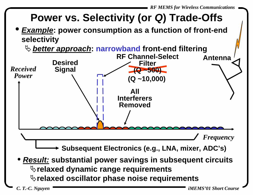
Power vs. Selectivity (or Q) Trade-Offs• Example: power consumption as a function of front-end
selectivitybetter approach: narrowband front-end filtering
C. T.-C. Nguyen
RF MEMS for Wireless Communications
iMEMS’01 Short Course
ReceivedPower
Frequency
DesiredSignal
Antenna
Subsequent Electronics (e.g., LNA, mixer, ADC’s)• Result: substantial power savings in subsequent circuits
relaxed dynamic range requirementsrelaxed oscillator phase noise requirements
(Q ~10,000)
AllInterferersRemoved
Power vs. Selectivity (or Q) Trade-Offs• Example: power consumption as a function of front-end
selectivitybetter approach: narrowband front-end filtering
RF Channel-SelectFilter
(Q ~500)

C. T.-C. Nguyen
RF MEMS for Wireless Communications
iMEMS’01 Short Course
ReceivedPower
Frequency
Antenna
Subsequent Electronics (e.g., LNA, mixer, ADC’s)
Front-End Channel Selector
FilterOn
FilterOn
FilterOn
FilterOn
• Power Saving Strategy: select channels right up at RF• One Approach: Use a highly selective low-loss filter that
is tunable from channel to channel:
• Problem: high filter selectivity (i.e., high Q) often precludes tunability
C. T.-C. Nguyen
RF MEMS for Wireless Communications
iMEMS’01 Short Course
Voltage-Controllable Center Frequency

C. T.-C. Nguyen
RF MEMS for Wireless Communications
iMEMS’01 Short Course
ReceivedPower
Frequency
Antenna
Subsequent Electronics (e.g., LNA, mixer, ADC’s)
FilterOn
FilterOn
FilterOn
FilterOn
• Solution: rather than cover the band by tuning, cover with a bank of switchable filters
• Problem: macroscopic high-Q filters are too big• Requirement: tiny filters μmechanical high-Q filters
present a good solution
Front-End Channel Selector

C. T.-C. Nguyen
RF MEMS for Wireless Communications
iMEMS’01 Short Course
MEMS vs. SAW Comparison
• MEMS offers the same or better high-Q frequency selectivity with orders of magnitude smaller size

C. T.-C. Nguyen
RF MEMS for Wireless Communications
iMEMS’01 Short Course
Micromechanical RF Pre-Selector• Use a massively parallel array of tunable, switchable filters
tiny size and zero dc power consumption ofμmechanical filters allows this

C. T.-C. Nguyen
RF MEMS for Wireless Communications
iMEMS’01 Short Course
Outline• Miniaturization of Transceivers
the need for high-Q• Receiver Design and Operation• Oscillator Fundamentals and Needs• Medium-Q Tunable μMech. Capacitors• Medium-Q Micromachined Inductors• High-Q Micromechanical Resonators• High-Q Micromechanical Filters• Micromechanical Mixer-Filters• Micromechanical Switches• Integration Technologies• Power Savings Via High-Q MEMS• ConclusionsΚ

C. T.-C. Nguyen
RF MEMS for Wireless Communications
iMEMS’01 Short Course
Conclusions• Via enhanced selectivity on a massive scale,
micromechanical circuits using high-Q elements have the potential for shifting communication transceiver design paradigms, greatly enhancing their capabilities
• Advantages of Micromechanical Circuits:orders of magnitude smaller size than present mechanical resonator devicesbetter performance than other single-chip solutionspotentially large reduction in power consumptionalternative transceiver architectures that maximize the use of high-Q, frequency selective devices for improved performance… but there’s much more to it than just the above ...

C. T.-C. Nguyen
RF MEMS for Wireless Communications
iMEMS’01 Short Course
Transistor Signal Processors
• Signal Processor Block:
Sin
Tin
Sout
Tout
t
Sin
t
Sout
Key Design Property: High Gain
C. T.-C. Nguyen
RF MEMS for Wireless Communications
iMEMS’01 Short Course
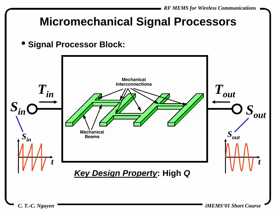
Micromechanical Signal Processors
• Signal Processor Block:
Sin
Tin
Sout
Tout
Key Design Property: High Qt
Sin
t
Sout

C. T.-C. Nguyen
RF MEMS for Wireless Communications
iMEMS’01 Short Course
Micromechanical Signal Processors
μmechanical resonators can potentially implement a substantial portion of a receiver’s RF front end

C. T.-C. Nguyen
RF MEMS for Wireless Communications
iMEMS’01 Short Course
Conclusions• Compelling parallels between MEMS and integrated
transistor signal processor technologies:Before 1960: discrete transistor circuits wired on boards with limited functionalityAfter IC’s: VLSI CPU’s and memory circuits have revolutionized the way things are doneToday: discrete mechanical circuits coupled by welded wires with limited functionalityWith VLSI Micromechanical Signal Processors:
functions never before possible now realizable via a combination of transistor and mechanical circuits?a functional and system architectural revolution reminiscent of the IC revolution?
… potential for true revolution? …… but there is much work yet to be done …

C. T.-C. Nguyen
RF MEMS for Wireless Communications
iMEMS’01 Short Course
Selected Readings

C. T.-C. Nguyen
RF MEMS for Wireless Communications
iMEMS’01 Short Course
Overviews and MEMS-Based Architectures[1] C. T.-C. Nguyen, L. P.B. Katehi, and G. M. Rebeiz, “Micromachined
devices for wireless communications (invited),” Proc. IEEE, vol. 86, no. 8, pp. 1756-1768, Aug. 1998.
[2] C. T.-C. Nguyen, “Frequency-selective MEMS for miniaturized low-power communication devices (invited),” IEEE Trans. Microwave Theory Tech., vol. 47, no. 8, pp. 1486-1503, Aug. 1999.
[3] C. T.-C. Nguyen, “Micromechanical circuits for communication transceivers (invited),” Proceedings, 2000 Bipolar/BiCMOSCircuits and Technology Meeting (BCTM), Minneapolis, Minnesota, September 25-26, 2000, pp. 142-149.
[4] C. T.-C. Nguyen, “Micromechanical circuits for communications (invited),” Proceedings, 2000 Int. Conference on High Density Interconnect and Systems Packaging, Denver, Colorado, April 25-28, 2000, pp. 112-117.
[5] C. T.-C. Nguyen, “Vibrating RF MEMS for low power wireless communications (invited),” to be published in the Proceedings of the 2001 Int. MEMS Workshop, Singapore, July 4-6, 2001.

C. T.-C. Nguyen
RF MEMS for Wireless Communications
iMEMS’01 Short Course
Micromechanical Tunable Capacitors[1] D. J. Young and B. E. Boser, “A micromachined variable capacitor
for monolithic low-noise VCOs,” Technical Digest, 1996 Solid-State Sensor and Actuator Workshop, Hilton Head Island, South Carolina, June 3-6, 1996, pp. 86-89.
[2] J.-B. Yoon and C. T.-C. Nguyen, “A high-Q tunable micromechanical capacitor with movable dielectric for RF applications,” Technical Digest, IEEE Int. Electron Devices Meeting, San Francisco, California, Dec. 11-13, 2000, pp. 489-492.
[3] A. Dec and K. Suyama, “Micromachined electro-mechanically tunable capacitors and their applications to RF IC’s,” IEEE Trans. Microwave Theory Tech., vol. 46, pp. 2587-2596, Dec. 1998.
[4] A. Dec and K. Suyama, “A 1.9GHz CMOS VCO with micromachinedelectromechanically tunable capacitors,” IEEE J. Solid-State Circuits, vol. 35, pp. 1231-1237, Aug. 2000.
[5] Z. Feng, W. Zhang, B. Su, K. F. Harsh, K. C. Gupta, V. M. Bright, and Y. C. Lee, “Design and modeling of RF MEMS tunable capacitors using electro-thermal actuators,” 1999 IEEE MTT-S Int. Microwave Symposium, Baltimore, MD, June 8-11, 1999.

C. T.-C. Nguyen
RF MEMS for Wireless Communications
iMEMS’01 Short Course
Micromachined Inductors[1] D. J. Young, V. Malba, J.-J. Ou, A. F. Bernhardt, and B. E. Boser,
“Monolithic high-performance three-dimensional coil inductors for wireless communication applications,” Technical Digest, IEEE International Electron Devices Meeting, Washington, D. C., Dec. 8-11, 1997, pp. 67-70.
[2] J. A. Von Arx and K. Najafi, “On-chip coils with integrated cores for remote inductive powering of integrated microsystems,” Digest of Technical Papers, 1997 International Conference on Solid-State Sensors and Actuators (Transducers’97), Chicago, Illinois, June 16-19, 1997, pp. 999-1002.
[3] B. Ziaie, N. K. Kocaman, and K. Najafi, “A generic micromachined silicon platform for low-power, low-loww miniature transceivers,”Digest of Technical Papers, 1997 International Conference on Solid-State Sensors and Actuators (Transducers’97), Chicago, Illinois, June 16-19, 1997, pp. 257-260.
[4] M. G. Allen, “Micromachined intermediate and high frequency inductors,” 1997 IEEE International Symposium on Circuits and Systems, Hong Kong, June 9-12, 1997, pp. 2829-2832.

C. T.-C. Nguyen
RF MEMS for Wireless Communications
iMEMS’01 Short Course
Micromachined Inductors (cont.)[5] C. H. Ahn, Y. J. Kim, and M. G. Allen, “A fully integrated
micromachined toroidal inductor with nickel-iron magnetic core (the switched DC/DC boost converter application),” Digest of Technical Papers, the 7th International Conference on Solid-State Sensors and Actuators (Transducers’93), Yokohama, Japan, June 7-10, 1993, pp. 70-73.
[6] J. B. Yoon, et al., “Monolithic high-Q overhang inductors fabricated on silicon and glass substrates,” Tech. Digest, 1999 Int. Electron Devices Meeting, Washington, D. C., pp. 753-756.

C. T.-C. Nguyen
RF MEMS for Wireless Communications
iMEMS’01 Short Course
Vibrating μMechanical Resonators[1] H. Nathanson, W. E. Newell, R. A. Wickstrom, and J. R. Davis, Jr.,
“The resonant gate transistor,” IEEE Trans. Electron Devices, vol. ED-14, No. 3, pp. 117-133, March 1967
[2] R. T. Howe and R. S. Muller, “Resonant microbridge vapor sensor,” IEEE Trans. Electron Devices, ED-33, pp. 499-506, 1986.
[3] F. D. Bannon III, J. R. Clark, and C. T.-C. Nguyen, “High frequency micromechanical filters,” IEEE J. Solid-State Circuits, vol. 35, no. 4, pp. 512-526, April 2000.
[4] K. Wang and C. T.-C. Nguyen, “High-order medium frequency micromechanical electronic filters,” IEEE/ ASME J.Microelectromech. Syst., vol. 8, no. 4, pp. 534-557, Dec. 1999.
[5] W. C. Tang, T.-C. H. Nguyen, and R. T. Howe, “Laterally drivenpolysilicon resonant microstructures,” Sensors and Actuators, 20, 25-32, 1989.
[6] C. T.-C. Nguyen and R. T. Howe, “An integrated CMOS micromechanical resonator high-Q oscillator,” IEEE J. Solid-State Circuits, vol. 34, no. 4, pp. 440-445, April 1999.

C. T.-C. Nguyen
RF MEMS for Wireless Communications
iMEMS’01 Short Course
Vibrating μMechanical Resonators (cont.)[7] H. A. C. Tilmans, “Equivalent circuit representation of
electromechanical transducers: I. lumped-parameter systems,” J.Micromech. Microeng., 6, pp. 157-176 (1996).
[8] H. A. C. Tilmans and R. Legtenberg, “Electrostatically driven vacuum-encapsulated polysilicon resonators: Part II. Theory and performance,” Sensors and Actuators, vol. A45 (1994), pp. 67-84.
[9] M. L. Roukes, “Nanoelectromechanical systems,” Tech. Digest, 2000 Solid-State Sensor and Actuator Workshop, Hilton Head Island, South Carolina, June 4-8, 2000, pp. 367-376.
[10] J. R. Clark, W.-T. Hsu, and C. T.-C. Nguyen, “High-Q VHF micromechanical contour-mode disk resonators,” Technical Digest, IEEE Int. Electron Devices Meeting, San Francisco, California, Dec. 11-13, 2000, pp. 399-402.
[11] W.-T. Hsu, J. R. Clark, and C. T.-C. Nguyen, “Mechanically temperature compensated flexural-mode micromechanical resonators,” Technical Digest, IEEE Int. Electron Devices Meeting, San Francisco, California, Dec. 11-13, 2000, pp. 493-496.

C. T.-C. Nguyen
RF MEMS for Wireless Communications
iMEMS’01 Short Course
Vibrating μMechanical Resonators (cont.)[12] J. R. Vig and Y. Kim, “Noise in microelectromechanical system
resonators,” IEEE Trans. Utrason. Ferroelec. Freq. Contr., vol. 46, no. 6, pp. 1558-1565, Nov. 1999.
[13] R. Navid, J. R. Clark, M. Demirci, and C. T.-C. Nguyen, “Third-orderintermodulation distortion in capacitively-driven CC-beam micromechanical resonators,” Technical Digest, 14th Int. IEEE Micro Electro Mechanical Systems Conference, Interlaken, Switzerland, Jan. 21-25, 2001, pp. 228-231.
C. T.-C. Nguyen
RF MEMS for Wireless Communications
iMEMS’01 Short Course
Vibrating μMechanical Filters[1] F. D. Bannon III, J. R. Clark, and C. T.-C. Nguyen, “High frequency
micromechanical filters,” IEEE J. Solid-State Circuits, vol. 35, no. 4, pp. 512-526, April 2000.
[2] K. Wang and C. T.-C. Nguyen, “High-order medium frequency micromechanical electronic filters,” IEEE/ ASME J.Microelectromech. Syst., vol. 8, no. 4, pp. 534-557, Dec. 1999.
[3] J. R. Clark, A.-C. Wong, and C. T.-C. Nguyen, “Parallel-resonator HF Micromechanical Bandpass Filters,” Digest of Technical Papers, 1997 International Conference on Solid-State Sensors and Actuators, Chicago, Illinois, June 16-19, 1997, pp. 1161-1164.
[4] C. T.-C. Nguyen, A.-C. Wong, and H. Ding, “Tunable, switchable, high-Q VHF microelectromechanical bandpass filters,” Digest of Technical Papers, 1999 IEEE International Solid-State Circuits Conference, San Francisco, California, Feb. 15-17, 1999, pp. 78-79, 448.
[5] R. A. Johnson, Mechanical Filters in Electronics. New York: John Wiley & Sons, 1983.
C. T.-C. Nguyen
RF MEMS for Wireless Communications
iMEMS’01 Short Course
Vibrating μMechanical Mixer-Filters[1] A.-C. Wong, H. Ding, and C. T.-C. Nguyen, “Micromechanical
mixer+filters,” Technical Digest, IEEE International Electron Devices Meeting, San Francisco, California, Dec. 6-9, 1998, pp. 471-474.

C. T.-C. Nguyen
RF MEMS for Wireless Communications
iMEMS’01 Short Course
Micromechanical Switches[1] C. Goldsmith, J. Randall, S. Eshelman, T. H. Lin, D. Denniston, S.
Chen and B. Norvell, “Characteristics of micromachined switches at microwave frequencies,” IEEE MTT-S Digest, pp. 1141-1144, June, 1996.
[2] Z. Jamie Yao, S. Chen, S. Eshelman, D. Denniston, and C. Goldsmith, “Micromachined low-loss microwave switches,” J.Microelectromech. Syst., vol. 8, no. 2, pp. 129-134, June 1999.
[3] J. J. Yao and M. F. Chang, “A surface micromachined miniature switch for telecommunication applications with signal frequencies from DC up to 4 GHz,” Tech. Digest, Int. Solid-State Sensor and Actuator Conference (Transducers’95), Stockholm, Sweden, June 1995.
[4] S. Pacheco, C. T.-C. Nguyen, and L. P. B. Katehi, “Micromechanical electrostatic K-band switches,” Proceedings, IEEE MTT-S Int. Microwave Symposium, Baltimore, Maryland, June 7-12, 1998, pp. 1569-1572.
[5] S. Pacheco, L. P. B. Katehi, and C. T.-C. Nguyen, “Design of low actuation voltage RF MEMS switches,” Proceedings, IEEE MTT-S Int. Microwave Symposium, Boston, Massachusetts, June 11-16, 2000.

C. T.-C. Nguyen
RF MEMS for Wireless Communications
iMEMS’01 Short Course
Micromechanical Switches (cont.)[5] E. K. Chan, E. C. Kan, R. W. Dutton, and P. M. Pinsky, “Nonlinear
dynamic modeling of micromachined microwave switches,”Proceedings, IEEE MTT-S Int. Microwave Symposium, Denver, Colorado, June 1997, pp. 1511-1514.

C. T.-C. Nguyen
RF MEMS for Wireless Communications
iMEMS’01 Short Course
Circuit/μMechanics Integration Technologies[1] T. A. Core, W. K. Tsang, S. J. Sherman, “Fabrication technology for
an integrated surface-micromachined sensor,” Solid State Technology, pp. 39-47, Oct. 1993.
[2] J. H. Smith, S. Montague, J. J. Sniegowski, J. R. Murray, et al., “Embedded micromechanical devices for the monolithic integration of MEMS with CMOS,” Tech. Digest, IEEE Int. Electron Devices Meeting (IEDM), Washington, D.C., Dec. 10-13, 1995, pp. 609-612.
[3] J. M. Bustillo, G. K. Fedder, C. T.-C. Nguyen, and R. T. Howe, “Process technology for the modular integration of CMOS andpolysilicon microstructures,” Microsystem Technologies, 1 (1994),pp. 30-41.
[4] C. T.-C. Nguyen and R. T. Howe, “An integrated CMOS micromechanical resonator high-Q oscillator,” IEEE J. Solid-State Circuits, vol. 34, no. 4, pp. 440-445, April 1999.
[5] A. E. Franke, D. Bilic, D. T. Chang, P. T. Jones, T.-J. King, R. T.Howe, and G. C. Johnson, “Post-CMOS integration of germanium microstructures,” Technical Digest, 12th Int. IEEE MEMS Conf., Orlando, FA, Jan. 17-21, 1999, pp. 630-637.
C. T.-C. Nguyen
RF MEMS for Wireless Communications
iMEMS’01 Short Course
Circuit/μMechanics Integration Technologies[6] H. Baltes, O. Paul, and O. Brand, “Micromachined thermally based
CMOS microsensors,” Proc. IEEE, vol. 86, no. 8, pp. 1660-1678, Aug. 1998.
[7] G. K. Fedder, S. Santhanam, M. L. Reed, S. C. Eagle, D. F. Guillou, M. S.-C. Lu, and L. R. Carley, “Laminated high-aspect-ratio microstructures in a conventional CMOS process,” Sensors and Actuators, vol. A57, no. 2, pp. 103-110, March 1997.
[8] A.-C. Wong, Y. Xie, and C. T.-C. Nguyen, “A bonded-micro-platform technology for modular merging of RF MEMS and transistor circuits,” to be published in the Digest of Technical Papers, the 11th Int. Conf. on Solid-State Sensors & Actuators (Transducers’01), Munich, Germany, June 10-14, 2001 (4 pages).