appendix f: tunnel systems b-3_independent tunnel...i i-81 independent feasibility study november...
TRANSCRIPT

APPENDIX F: TUNNEL SYSTEMS
I-81 Independent Feasibility Study November 2017 | APPENDIX F

i I-81 Independent Feasibility Study November 2017 | APPENDIX F
TABLE OF CONTENTS1 TUNNEL SYSTEMS 1
1.1 Introduction 1
1.2 Fire Protection and Life Safety Provisions 1
1.3 NFPA 502 Compliance and Authority Having Jurisdiction 1
1.4 Tunnel Ventilation 2
1.5 Standards of Reference 2
1.6 Critical Determinations 2
1.7 Normal Ventilation 3
1.8 Portal Emissions 3
1.9 Portal Air Recirculation 4
1.10 Continuous Emission Monitoring 4
1.11 Emergency Ventilation and Smoke Management 4
1.12 Egress Passage or Stairway Pressurization 4
1.13 Tunnel Ventilation System Operation 4
1.14 Recommended Ventilation Options for I-81 Tunnel Alternatives 5
1.15 Summary 6
2 TUNNEL FIRE PROTECTION & SUPPRESSION SYSTEMS 82.1 Overview 8
2.2 Applicable Standards 9
2.3 Fire Protection System Design Considerations 9
3 TUNNEL LIGHTING 103.1 Overview 10
3.2 Standards and References 10
3.3 Design Consderations 10
3.4 Tunnel Lighting Control Systems 10
3.5 Tunnel Lighting Fixture Circuiting 10
3.6 Tunnel Lighting Fixtures 10
3.7 Tunnel Egress Stairwells and Ancillary Spaces 11
3.8 Tunnel Fixed Message Sign lighting 11
3.9 Approach Lighting 11
4 TUNNEL FINISHES 12
4.1 Overview 12
4.2 Codes, Standards & References 12
4.3 Highway Architecture Elements 12
4.4 Interior Tunnel Elements 12
4.5 Tunnel Emergency Egress 15
5 ELECTRICAL SYSTEMS 165.1 Overview 16
5.2 Power Distribution System 16
5.3 Fire Alarm and Detection Systems 17
5.4 Emergency Communication Systems 17
5.5 Security Systems 17
5.6 Supervisory Control, Monitoring and Data Acquisition (SCADA) System 17
5.7 Traffic Control 18
5.8 Typical Dynamic Message System 18
6 TUNNEL DRAINAGE SYSTEMS 196.1 Overview 19
6.2 Applicable Standards 19
6.3 Drainage System Discharge Considerations 19
6.4 Drainage System Capacity Basis 19
6.5 Drainage System Piping 19
6.6 Drainage System Pumps and Pump Stations 19
7 TUNNEL OPERATIONS AND MAINTENANCE 207.1 Overview 20
7.2 Operations & Maintenance Plan 20
7.3 Concept of Operations 20

ii APPENDIX F | I-81 Independent Feasibility Study November 2017
FIGURESFIGURE 1: Fire and Life Safety Committee (FLSC) Process 2
FIGURE 2: Jet Fan System (from NFPA 502) 2
FIGURE 3: Semi-Traverse Point Exhaust System (from NFPA 502) 2
FIGURE 4: Portal Emission Prevention 3
FIGURE 5: Smoke Extraction via Point Exhaust 4
FIGURE 7: Single Bore Stacked Tunnel with Jet Fan Installation 5
FIGURE 6: Twin Bored Tunnel with Jet Fan Installation 5
FIGURE 9: Activated FFFS 9
FIGURE 8: Typical Standpipe Hose Valve Cabinet 9
FIGURE 10: Construction Photo of Twin Bored Tunnel Portals and Approach Roadway Section 12
FIGURE 11: View of Bored Tunnel Showing Finish Features 12
FIGURE 12: Stainless Equipment Cabinet for Fire Hose Valve and Extinguisher 13
FIGURE 13: Example of Various Types of Signs Utilized in Road Tunnels to Identify Safety Related Features 13
FIGURE 14: Tunnel Emergency Egress 13
FIGURE 15: Photo showing egress opening, traffic barrier with angled interruption, painted board fireproofing, signage, and equipment cabinets 13
FIGURE 16: Photo Showing Raised Safety Walk in Concrete Traffic Barrier 13
FIGURE 17: Stainless Steel Sliding Egress Door 14
FIGURE 18: Construction Photo Showing Stainless Steel Sliding Egress Door inside Egress Corridor 14
FIGURE 19: Stacked Single Bore Tunnel with Interconnecting Egress Stairs (Seattle Tunnel, WA) 15
FIGURE 20: Twin Bored Tunnel Configurations with Cross Passages (bores can be at the same level or different levels (WSP USA renderings)) 15
FIGURE 21: Cross Passage between Two Bored Tunnels Showing sliding door (open at far end), illuminated exit sign, equipment cabinets, pressurization fans, and emergency lighting fixtures (Port of Miami Tunnel) 15
FIGURE 22: Cross Passage between Two Bored Tunnels (showing sliding door (open at far end), illuminated exit sign, equipment cabinets, pressurization fans, and emergency lighting fixtures (Port of Miami Tunnel)) 15
FIGURE 23: Rendering of Single Bore Stacked Tunnel Option 15
FIGURE 24: Tunnel Incident Viewed on Closed Circuit Television System 18
FIGURE 25: Dynamic (Variable) Message Signs (DMS) 18
FIGURE 26: Typical Lane Use Signals 18
FIGURE 27: Tunnel Centralized Control and Operations Concept 21
FIGURE 28: Example Control Room 21
TABLESTABLE 1: Design Fire Data Based on Vehicle Type (NFPA 502) 3
TABLE 2: Summary of Ventilation Options (refer Table 3 and Table 4 for ventilation scheme details) 6
TABLE 3: Summary of Ventilation Schemes for Twin Bore Tunnel Alternatives (Red, Blue and Orange alternatives) 6
TABLE 4: Summary of Ventilation Schemes for Single Bore Stacked Tunnel Alternatives (Green A alternative) 7
TABLE 5: Recent US Tunnels with FFFS 8
TABLE 6: Daytime Supplemental Lighting Consideration 10

I-81 Independent Feasibility Study November 2017 | APPENDIX F1
1 TUNNEL SYSTEMS1.1 INTRODUCTIONEach of the alternative tunnel options being considered for I-81 will require a variety of operational systems and features within the tunnel in order to support safe traffic operations and to provide the necessary level of fire protection and life safety. The various tunnel systems and features that will be required include:
o Traffic control and monitoring
o Roadway lighting
o Electrical power
o Communications
o Equipment control and monitoring (SCADA)
o Security
o Fire detection and alarm
o Fire protection and suppression
o Ventilation
o Drainage
o Emergency egress
o Tunnel finishes
1.2 FIRE PROTECTION AND LIFE SAFETY PROVISIONS
The specific requirements for the systems and elements necessary to meet the fire protection and life safety goals for any of the tunnel alternatives being considered for I-81 would be based on the minimum requirements established in National Fire Protection Association (NFPA) 502 Standard for Road Tunnels, Bridges, and Other Limited Access Highways. The fire protection and life
safety provisions required by NFPA 502 are based on the tunnel’s length and a site-specific assessment.
The I-81 tunnel alternative study area is an urban corridor that can be assumed to have a generally high volume of traffic inclusive of cars, buses and heavy goods vehicles. Emergency response agencies are assumed to be available within generally close proximity. Based on this, and the fact that the four tunnel alternatives being considered range between 1 mile to 2 miles in length, the fire protection and life safety requirements will be the same for each tunnel alternative and will include provision of the following:
o An engineering analysis to establish overall fire protec-tion and life-safety concept
o Means for emergency egress and access
o Tunnel ventilation
o Tunnel fire suppression system
o Tunnel drainage systems
o Traffic control and monitoring
o Tunnel emergency lighting
o Fire alarm and detection
o Electrical power distribution
o Emergency communications
o Structural fire protection
o Exit and other special signage
o Intrusion detection/access control
o Emissions monitoring
o Emergency and incident management plans
The above provisions have certain prescribed aspects many of which are performance-based. For example, a key requirement in NFPA 502 is the ability to establish tenable conditions in the case of a fire event in order to provide a safe path for the evacuation of motorists and to also facilitate response by fire fighters and other emergency personnel. Achieving these goals relies on the interaction of the tunnel ventilation system, available means
of emergency egress and fire control. The assessment of whether or not tenable conditions are achievable can be subjective and depends on several factors, including but not limited to, the design fire, egress locations, ventilation approach, and provision of firefighting systems. NFPA 502 requires an engineering analysis that holistically considers the interaction of all available provisions and their ability to achieve the overall fire protection and life safety goal.
Given the potential for subjective interpretations and approaches when developing a performance-based approach to fire-life safety design, a consensus approach between stakeholders is needed in order to develop a credible set of design criteria, design basis and subsequent design. The Authority Having Jurisdiction (AHJ) is a critical stakeholder in this consensus approach to development of a fire-life safety strategy and design.
1.3 NFPA 502 COMPLIANCE AND AUTHORITY HAVING JURISDICTION
NFPA 502 defines the Authority Having Jurisdiction as “an organization, office, or individual responsible for enforcing the requirements of a code or standard, or for approving equipment, materials, an installation, or a procedure”.
In most municipalities the AHJ is a designee of the fire services (either local or state) such as the fire marshal or district chief; however, in certain jurisdictions the designated AHJ may be the tunnel owner or operating authority as they have the overall responsibility for the facility. For a large infrastructure project like the development of a road tunnel for the I-81 corridor through Syracuse, a variety of other agencies and stakeholders will have formal and informal input during the planning process. For instance, the following organizations would be expected to have a significant role in defining and planning the traffic operations, life safety goals, incident management and emergency preparedness and response:
o First responders (local fire and police)
o State police
o Emergency medical services
o Hazardous material/spill units
o New York State Department of Transportation
o Federal Highway Administration
o City of Syracuse
o Local and state permitting and regulatory agencies
o Design consultants
NFPA 502 defers to the Authority Having Jurisdiction (AHJ) for the enforcement of its provisions. Therefore, the approach toward the implementation of NFPA 502 begins with the identification of the AHJ. It is then recommended that a “Fire and Life Safety Committee” (FLSC) be established to engage in a partnered approach with the key project participants, agencies and stakeholders in establishing the life safety design goals to be implemented as part of the tunnel design and construction phases, and ensuring they are in unison with the tunnel’s operational concept for emergency and incident management response. The protocol of the FLSC will be to act as the technical and policy overseer for the safety issues affecting the tunnel and to make all key decisions and determinations by consensus. During preliminary planning stages the owner should facilitate a FLSC process and document the decisions as part of a NFPA 502 Compliance Report. The report will document all decisions made relative to the implementation of NFPA 502, including any traffic restrictions such as banning of bulk fuel carriers and other hazardous cargo vehicles, and identify any specific exceptions. This report would then serve as the “AHJ approved” life safety design criteria for the tunnel. The graphic below outlines the recommended FLSC process.

2 APPENDIX F | I-81 Independent Feasibility Study November 2017
1.4 TUNNEL VENTILATIONVentilation is a critical key to providing safe conditions within road tunnels. During normal traffic operations, ventilation is required to maintain the in-tunnel air quality by preventing the dangerous accumulation of vehicle-emitted pollutants (i.e., carbon monoxide, CO, and oxides of nitrogen, NOx) and to maintain visibility in the tunnel by preventing the accumulation of haze-producing pollutants. In the event of a fire emergency the tunnel ventilation system performs a major role in providing life safety support by controlling the flow of smoke and heat in a manner that protects motorists and facilitates evacuation and fire fighter access.
For normal tunnel operations, the tunnel length, traffic volume, and the direction of traffic movement (unidirectional versus bidirectional) are some of the key factors in determining whether the ventilation requirements can be achieved by passive means (the piston action airflow generated by the moving vehicles) or whether mechanical ventilation is required. The tunnel length is also a key factor in determining the need for mechanical ventilation during emergency operations, since it affects the overall pollution being emitted from the tunnel, and for a fire it affects the egress time from the tunnel, the number of motorists that could be exposed to the hazards of a fire, the degree of difficulty for fire department or emergency services intervention (longer is more difficult to access) and the overall probability of a fire (longer tunnels will have a greater fire probability).
Based on modern US road tunnels comparable to the I-81 tunnel alternatives being considered herein, a mechanical ventilation system will be required. The installed ventilation system capacity will ultimately be determined by the requirement for emergency smoke control during a tunnel fire incident (emergency operations). The ventilation requirements during normal tunnel operation (non-fire conditions) will be significantly less and determined by the prevailing traffic conditions.
The most likely applicable ventilation options for the various tunnel alternatives being considered herein for I-81 include a longitudinal system utilizing in-tunnel jet fans (Figure 2), a semi-transverse point exhaust using a duct and operable dampers (Figure 3) or, in the case of the longer tunnel alternatives, a combination of both system types.
1.5 STANDARDS OF REFERENCEThe design of road tunnel ventilation systems will be required to conform to the latest issues of the following standards and references:
o National Fire Protection Association – Standard for Road Tunnels, Bridges, & Other Limited Access High-ways (NFPA 502).
o American Society of Heating, Refrigeration, and Air Conditioning Engineers (ASHRAE) – Enclosed Vehicular Facilities.
o Recommended AASHTO Guidelines for Emergency Ventilation of Smoke in Road Tunnels.
o FHWA/EPA Guidance on CO Levels in Tunnels.
1.6 CRITICAL DETERMINATIONSThere are critical determinations to be made by the FLSC that will have a fundamental influence and affect to the overall approach to fire protection, life safety considerations, emergency response planning and tunnel system design in general which must be made in the early phase of any road tunnel project. These critical determinations are as follows:
1.6.1 DESIGN FIRE
The tunnel design fire is the fire size (heat release rate) that shall be considered in the design and planning for the fire protection and life safety provisions required. Therefore, selection of the design fire becomes one of the most critical determinations to the design of the tunnel systems. For example, NFPA 502 states the following: “The design of the emergency ventilation system shall be based on a fire scenario having defined heat release rates, smoke release rates, and carbon monoxide release rates, all varying as a function of time. The selection of the fire scenario shall consider the operational risks that are associated with the types of vehicles expected to use the tunnel. The fire scenario shall consider fire at a location where the most stringent ventilation system performance requirement is anticipated by an engineering analysis.”
FIGURE 1: Fire and Life Safety Committee (FLSC) Process
FIGURE 2: Jet Fan System (from NFPA 502)
FIGURE 3: Semi-Traverse Point Exhaust System (from NFPA 502)
3 I-81 Independent Feasibility Study November 2017 | APPENDIX F
1.6.2 TRAFFIC TYPE AND HAZARDOUS CARGO
Defining the normal traffic mix and allowable vehicle types is a critical determination necessary to selecting the appropriate design fire. Per NFPA 502, “The selection of the design fire size (heat release rate) shall consider the types of vehicles that are expected to use the tunnel.”
Given that I-81 is a major highway, it is reasonable to assume that a traffic fleet mix of cars, buses and heavy goods trucks would use the tunnel. However, should a tunnel alternative be implemented, it is necessary that the FLSC consider that fuel tankers and other regulated hazardous cargo vehicles be re-routed and not allowed to use the tunnel. I-481 provides a viable alternative interstate route. The practice of banning these types of vehicles from road tunnels is common practice in all US cities.
Table 1 has been excerpted from NFPA 502 and provides guidance on the magnitude of possible vehicular fires with respect to the types of vehicles that could use the tunnel. In assessing this data it is reasonable to assume that a multiple vehicle fire involving large heavy goods vehicles such as semi-trailer trucks could potentially reach a magnitude of up to 200 MW, according to NFPA 502. The representative fire heat release rate (FHRR) is 150 MW. Inclusion of a fixed firefighting system can be used as a basis to adopt a lower FHRR in the order of 70 – 100 MW.
1.7 NORMAL VENTILATIONDuring normal operating conditions the tunnel is expected to self-ventilate with free-flowing traffic. The piston action ventilation caused by traffic movement will be sufficient to maintain safe CO and opacity levels in the tunnels during free-flowing traffic conditions. Ventilation may need to be operated to provide dilution air during heavy traffic periods, when traffic speeds fall below 10 to 15 mph, and during adverse outdoor wind conditions. The tunnels will be continuously monitored for trends in the CO levels and rising CO levels will indicate the need for more dilution air, therefore additional pairs of fans would be activated until the CO levels are at acceptable levels.
The ventilation system must be sufficient to dilute the vehicle-emitted pollutants to safe levels. The limiting pollutant concentrations during normal tunnel operations have been established jointly by the FHWA and EPA. The guidelines are given in terms of allowable average CO concentration versus exposure time. In the US, CO is the primary pollutant of concern due to the large percentage of gasoline powered vehicles. Using ventilation to maintaining acceptable CO levels in a tunnel will also sufficiently maintain acceptable levels for all other vehicle emission constituents.
Fan operation during normal tunnel operations will be determined primarily on the basis of the carbon monoxide (CO) level in the tunnel. The tunnels should be continuously monitored for CO at a suitable number of locations. In addition, if a relatively large percentage of diesel powered trucks and buses are anticipated it is recommended to monitor the opacity of the tunnel air (haze) to ensure a safe level of visibility. The monitored data can be transmitted to control room where the data will be displayed for use by the system operators and automatic control system.
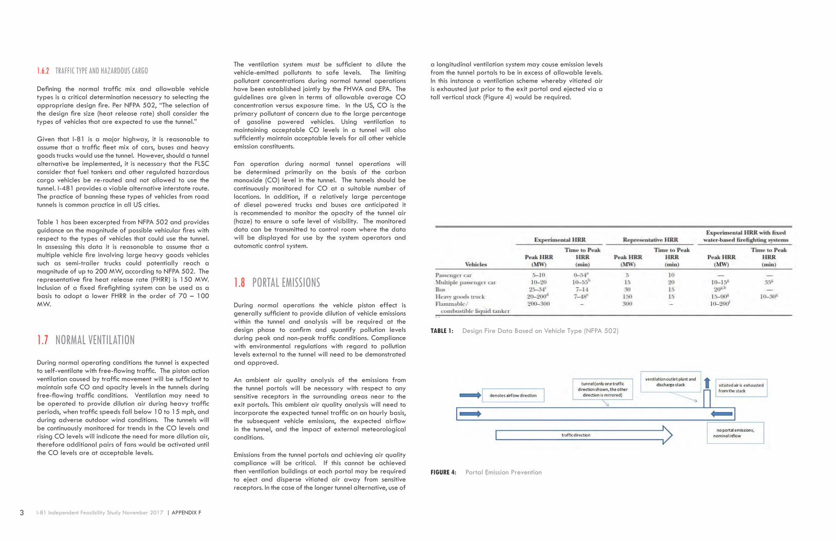
1.8 PORTAL EMISSIONSDuring normal operations the vehicle piston effect is generally sufficient to provide dilution of vehicle emissions within the tunnel and analysis will be required at the design phase to confirm and quantify pollution levels during peak and non-peak traffic conditions. Compliance with environmental regulations with regard to pollution levels external to the tunnel will need to be demonstrated and approved.
An ambient air quality analysis of the emissions from the tunnel portals will be necessary with respect to any sensitive receptors in the surrounding areas near to the exit portals. This ambient air quality analysis will need to incorporate the expected tunnel traffic on an hourly basis, the subsequent vehicle emissions, the expected airflow in the tunnel, and the impact of external meteorological conditions.
Emissions from the tunnel portals and achieving air quality compliance will be critical. If this cannot be achieved then ventilation buildings at each portal may be required to eject and disperse vitiated air away from sensitive receptors. In the case of the longer tunnel alternative, use of
TABLE 1: Design Fire Data Based on Vehicle Type (NFPA 502)
a longitudinal ventilation system may cause emission levels from the tunnel portals to be in excess of allowable levels. In this instance a ventilation scheme whereby vitiated air is exhausted just prior to the exit portal and ejected via a tall vertical stack (Figure 4) would be required.
FIGURE 4: Portal Emission Prevention

4 APPENDIX F | I-81 Independent Feasibility Study November 2017
1.9 PORTAL AIR RECIRCULATIONRecirculation of vitiated air at tunnel portals needs to be factored into a design if a system without point exhaust near the portal is used. Recirculation of vitiated air is typically managed by offsetting portals (by around 300 feet) or by providing a dividing wall structure.
1.10 CONTINUOUS EMISSION MONITORINGEmission monitors will be required in all tunnel alternatives to continuously monitor the levels of various pollutants and overall visibility. These systems will be utilized during normal traffic operations to regulate the ventilation system as needed for dilution of accumulated emissions or to signal an alarm when emission levels are exceeding their preset safe levels.
1.11 EMERGENCY VENTILATION AND SMOKE MANAGEMENT
In the case of a vehicle fire in the tunnel, longitudinal ventilation systems control the flow of smoke by producing a sufficient air velocity along the roadway to force the smoke movement downstream away from the fire site and the section of a tunnel most likely occupied by trapped motorists. The minimum air velocity required for smoke control is referred to as the critical velocity, that velocity which prevents reverse flow or back layering of smoke. The magnitude of the critical velocity is a function of the design fire heat release rate (fire size), the tunnel dimensions and the tunnel grade. The air flow induced in the tunnel must be sufficient to overcome the various resistances to flow (including vehicles in the tunnel, tunnel grade, adverse winds, etc.), while also exceeding the critical velocity.
Emergency ventilation and smoke management via a point exhaust system is achieved via a longitudinal duct (either over the roadway or in the side wall) with individually operable dampers. A schematic is provided in Figure 5. With a point exhaust system smoke is extracted from the roadway into a dedicated duct and dispersed via a remote fan shaft or fan building. The system is designed to contain smoke at/near the site of the fire and provide tenable conditions within the tunnel both upstream and
downstream of the incident. Point exhaust systems have been implemented in tunnels in Europe and Australia and currently is being implemented in the Alaska Way Tunnel in Seattle. Point exhaust systems require a dedicated duct along the length of the tunnel and a large number of individually controlled dampers. In addition, an ancillary facility is required as a centralized location to house the exhaust fans serving the duct.
1.12 EGRESS PASSAGE OR STAIRWAY PRESSURIZATION
During a significant tunnel fire event where evacuation may be necessary, pressurization of the egress paths (cross-passages or stairways) is needed to prevent smoke ingress and contamination of egress route. In many cases, cross-passageways and stairways can be pressurized by operation of the ventilation system in the connecting (non-incident) bore. Where this is not achievable a dedicated fan system may be necessary to provide sufficient pressurization of these spaces.
1.13 TUNNEL VENTILATION SYSTEM OPERATIONFor major urban road tunnels, such as that being considered for I-81, operation of ventilation systems during normal traffic conditions is typically arranged to be automatic based on pre-set level indications received from the emission monitoring system. In addition, alert/alarm indications regarding environmental conditions are also sent to a central operations control center so that any system adjustments can be manually made by a tunnel operator.
Jet fan based longitudinal ventilation systems do not require significant operator interaction or decision making that can lead to a delayed or incorrect response during a fire emergency. A point exhaust system requires the dampers near to the fire to be operated and, in the case of a vehicle fire, the appropriate response mode is dependent on the exact location of the fire within the tunnel. The ventilation system operation control software can be preprogrammed to operate the system in the appropriate mode based upon the operator’s identification of the fire location.
FIGURE 5: Smoke Extraction via Point Exhaust

5 I-81 Independent Feasibility Study November 2017 | APPENDIX F
1.14 RECOMMENDED VENTILATION OPTIONS FOR I-81 TUNNEL ALTERNATIVES
There are four tunnel alternatives identified herein for the potential replacement of the I-81 corridor through Syracuse, NY. The tunnel alternatives identified consist of differing length and alignment alternatives using two distinctly different variations of bored tunnel construction.
Each of the tunnel alternatives have been developed for two 12’ travel lanes with minimum 4’ shoulders on each side of the travel lanes, both northbound and southbound. Vertical vehicular clearance throughout is set at 16.0’.
The predominant bored tunnel variation for the different alternatives is a “single bore - stacked” tunnel with an upper and lower deck level that allow for the accommodation of northbound and southbound traffic separately. The Green A alternative assumes a single bore stacked tunnel option, and is approximately 5,800 feet in length.
The other bored tunnel variation being considered is referred to as the “twin bored tunnel” alternative which essentially consists of two separate and parallel bored tunnels that provide the necessary separation of northbound and southbound traffic. Alternatives considering the twin bore option range between 8,600 feet and 2.8 miles in length.
A longitudinal tunnel ventilation system using jet fans is recommended as the ventilation system design basis for each tunnel alternative with the inclusion of a point extraction system for the longer tunnel alternatives.
A jet fan based longitudinal ventilation system utilizes the jet fans to impart a high velocity air jet into the tunnel which induces a longitudinal flow along the length of the tunnel. The longitudinal flow in the tunnel pulls air into the entrance portal, and then the air travels the full length of the tunnel and is discharged out the other portal (options T1 and S1) or exhausted via a single extraction point (options T2, T3, S2 and S3).
Jet fans are typically mounted at the tunnel ceiling in pairs at longitudinal spacing of 300’. Reversible jet fans permit longitudinal flow in either direction.
A typical jet fan-sound attenuator unit has a 40” internal diameter, is about 17 feet long and weighs approximately 2,700 pounds.
Jet fan units are usually rated for high temperature operation as they are mounted in the tunnel and will be exposed to elevated temperatures in the event of a vehicle fire. In accordance with NFPA 502, the fans, their motors, and all related components that are exposed to the air stream must be able to remain operational for a minimum of 1 hour in an air stream temperature of 482 deg F (250 deg C). The system design will need to include an additional pair of fans in the tunnel bore to allow for the potential loss of a pair of fans by heat damage during a fire.
External wind conditions can have a significant effect on the operation of the longitudinal ventilation system. If the wind is acting opposite to the direction of ventilation, then the tunnel airflow will be reduced. The jet fan selections need to include the effect of adverse wind acting on the exiting portal.
Jet fans require a minimum clearance envelope in the order of 6’. For the twin bore tunnel options being considered for I-81 the diameter of the each tunnel bore is generally established based on the number of travel lanes, travel lane width, shoulder requirements, and vehicle height clearance. These parameters generally result in a tunnel diameter that is able to accommo-date jet fans mounted in the crown of the tunnel above the ve-hicle clearance envelope. Refer to Figure 6 for a single bore tunnel with a stacked road deck there is less available vertical clearance, especially on the lower deck. The resultant space for the ventilation equipment tends to be at the sides of the tunnel which may better serve as a ventilation duct for a point extraction system option since space limitations may still exclude use of jet fans. Refer to Figure 7.
A longitudinal ventilation system using jet fans is considered the most appropriate option for the basis of the four study alternatives because:
o It is the most efficient system for tunnels designed for unidirectional traffic.
o It has the least impact on size of the tunnel structure.
o It does not require ancillary space of facilities to house the fans
o It is the most cost effective system.
FIGURE 6: Twin Bored Tunnel with Jet Fan Installation
FIGURE 7: Single Bore Stacked Tunnel with Jet Fan Installation
6 APPENDIX F | I-81 Independent Feasibility Study November 2017
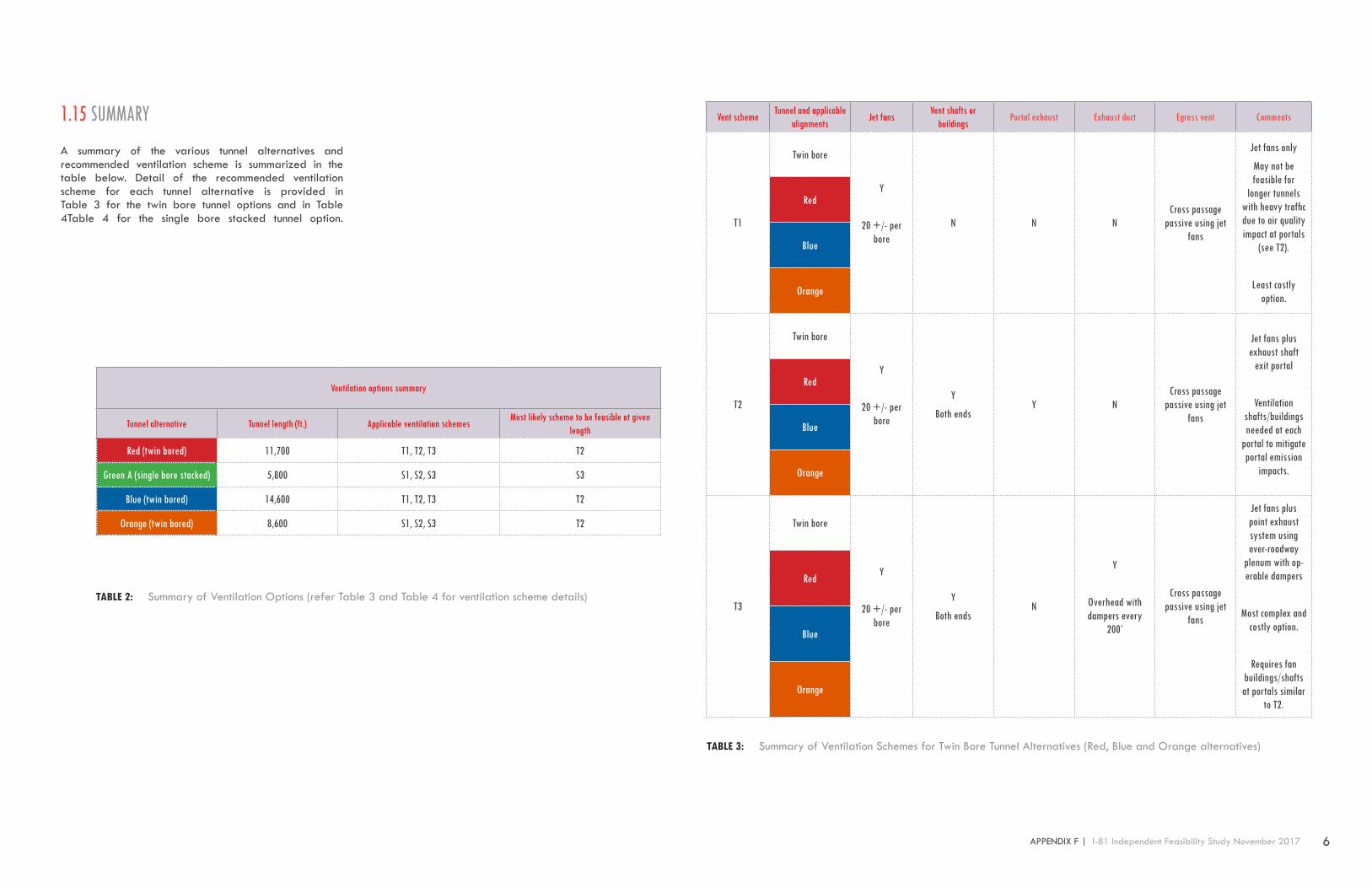
1.15 SUMMARYA summary of the various tunnel alternatives and recommended ventilation scheme is summarized in the table below. Detail of the recommended ventilation scheme for each tunnel alternative is provided in Table 3 for the twin bore tunnel options and in Table 4Table 4 for the single bore stacked tunnel option.
Ventilation options summary
Tunnel alternative Tunnel length (ft.) Applicable ventilation schemesMost likely scheme to be feasible at given
length
Red (twin bored) 11,700 T1, T2, T3 T2
Green A (single bore stacked) 5,800 S1, S2, S3 S3
Blue (twin bored) 14,600 T1, T2, T3 T2
Orange (twin bored) 8,600 S1, S2, S3 T2
Vent schemeTunnel and applicable
alignmentsJet fans
Vent shafts or buildings
Portal exhaust Exhaust duct Egress vent Comments
T1
Twin bore
Y
20 +/- per bore
N N NCross passage
passive using jet fans
Jet fans only
May not be feasible for
longer tunnels with heavy traffic due to air quality impact at portals
(see T2).
Least costly option.
Red
Blue
Orange
T2
Twin bore
Y
20 +/- per bore
Y
Both endsY N
Cross passage passive using jet
fans
Jet fans plus exhaust shaft
exit portal
Ventilation shafts/buildings needed at each
portal to mitigate portal emission
impacts.
Red
Blue
Orange
T3
Twin bore
Y
20 +/- per bore
Y
Both endsN
Y
Overhead with dampers every
200’
Cross passage passive using jet
fans
Jet fans plus point exhaust system using over-roadway
plenum with op-erable dampers
Most complex and costly option.
Requires fan buildings/shafts at portals similar
to T2.
Red
Blue
Orange
TABLE 2: Summary of Ventilation Options (refer Table 3 and Table 4 for ventilation scheme details)
TABLE 3: Summary of Ventilation Schemes for Twin Bore Tunnel Alternatives (Red, Blue and Orange alternatives)

7 I-81 Independent Feasibility Study November 2017 | APPENDIX F
Vent schemeTunnel and applicable
alignmentsJet fans
Vent shafts or buildings
Portal exhaust Exhaust duct Egress vent Comments
S1
Single bore, twin deck Y
20 +/- per bore
N N N Stairway, passive using jet fans
Jet fans only
Assume jet fans can be installed on both upper a lower roadway levels along the length of the tunnel (requires a large tunnel diameter)Same list of points as
per twin bore option T1Green A
S2
Single bore, twin deck
Y
6 +/- per bore
Y
Both endsN Y Stairway, dedicated
fans
Jet fans plus point exhaust sys-tem using side wall plenum with
operable dampers
Assume jet fans installed only at the transition sections into and
out of tunnel.
Exhaust ventilation duct runs along the side wall of the tunnel
with operable dampers every 200’
Most complex and costly option.
Requires fan buildings/shafts at portals.
Green A
S3
Single bore, twin deck Y
6 +/- per bore
Y
Both endsY N Stairway, dedicated
fans
Jet fans plus exhaust building/shaft at exit portal
Assume jet fans can be installed on both upper a lower roadway levels along the length of the
tunnel.
Portal area exhaust is required to mitigate air quality conditions.
Requires fan buildings/shafts at portals.
Green A
TABLE 4: Summary of Ventilation Schemes for Single Bore Stacked Tunnel Alternatives (Green A alternative)

8 APPENDIX F | I-81 Independent Feasibility Study November 2017
2 TUNNEL FIRE PROTECTION & SUPPRESSION SYSTEMS2.1 OVERVIEWNFPA 502 – Standard for Road Tunnel, Bridges, and Other Limited Access Highways establishes the provision of a fire protection standpipe system in road tunnels greater than 300 feet long as a mandatory requirement. Installation of a fixed firefighting system (deluge sprinkler type system) is defined by NFPA 502 to be a “conditionally” mandatory requirement for any tunnel greater than 1,000 feet - meaning that for any road tunnel longer than 1,000 feet an engineering analysis must be performed to determine the need and benefit of a fixed firefighting system for that particular road tunnel facility. Based on the lengths of the four tunnel alternatives considered within this report, it is assumed that both a standpipe system and a fixed firefighting system will be required for any of the selected alternatives.
Standpipe systems are utilized to provide a water supply to remote locations within a facility for use by firefighters. Standpipes are considered a manual system that allows firefighters the ability to connect hoses to the system at locations where needed to fight the fire.
Installation of fixed firefighting systems (FFFS) has become common in newly commissioned urban road tunnels within the US due to the increasing concern for potentially large multi-vehicle or heavy goods vehicle cargo fires which, in addition to their threat to life safety, also pose the threat to cause significant damage to the tunnel facility itself. FFFS are considered to be effective in these types of vehicle fires because of their ability to prevent the spread of the fire from one vehicle to another. Limiting a fire incident to the initial fuel source (single vehicle) will limit the potential size of the fire; thus mitigating the threat to both motorist life safety and damage to the structure. Table 5 provides a list of recent US road tunnels that have installed, or are planning, a FFFS. The table provides the operational data for the tunnels as well as the water application rate (density) of the FFFS.
In addition to requirements for a standpipe and fixed firefighting system, NFPA 502 also requires deployment of portable multi-purpose type fire extinguishers along the length of the tunnel. These extinguishers are to be conspicuously located and easily accessible for use by motorists in the case of a minor fire emergency.
Tunnel Alaska Way Tunnel Midtown Tunnel Port of Miami Tunnel Doyle Drive Tun-nels Eisenhower Tunnel
Location Seattle, WA Norfolk, VA Miami, FL San Francisco, CA Dillon, CO
Year opened UC 2016 2014 2015 1979
Length 9800 ft. 4054 ft. 4200 ft. 750 ft., 790 ft., 920 ft., 1030 ft. 8940 ft.
Bores 1, two level 1 2 4 tunnels (2 in each direc-tion) 2
New/Rehab New New New New Rehab 2016
Traffic Unidirectional, 2 lanes in each direction Unidirectional, 2 lanes Unidirectional, 2 lanes
per boreUnidirectional, 3 to 4
lanes per boreUnidirectional, 2 lanes
per bore
AADT 40,000 7000 34,000
Posted Speed 50 mph 45 mph 35 mph 65 mph 50 mph
Ventilation Jet fans, point exhaust Jet fan, longitudinal Jet fan, longitudinal Jet fan, longitudinal Transverse
Water application 0.30 gpm/ft2 0.15 gpm/ft2 0.20 gpm/ft2 0.20 gpm/ft2 0.16 gpm/ft2
Urban or rural Urban Urban Urban Urban Rural, mountain pass tunnel
EgressEgress passage up/
down,
650 ft. spacing
Egress corridor w/ doors spaced at 500 ft.
Cross passages, 650 ft. spacing Cross passages
TABLE 5: Recent US Tunnels with FFFS

9 I-81 Independent Feasibility Study November 2017 | APPENDIX F
2.2 APPLICABLE STANDARDSThe following standards serve as the basis for establishing tunnel fire protection and suppression system requirements:
o NFPA 502 – Standard for Road Tunnel, Bridges, and Other Limited Access Highways
o NFPA 14 – Standpipe Systems
o NFPA 13 – Sprinkler Systems
o NFPA 10 – Fire Extinguishers
NFPA Standards are not considered code unless adopted legislatively by the local Authority Having Jurisdiction (AHJ). For the purposes of this feasibility report the assumed requirements for fire protection and suppression systems will adhere to NFPA requirements.
2.3 FIRE PROTECTION SYSTEM DESIGN CONSIDERATIONS
2.3.1 STANDPIPE SYSTEM
Standpipe systems within road tunnels are allowed by NFPA 502 to be either “wet” or “dry” meaning that the systems may be continuously kept full and pressurized or remain empty until needed. Dry standpipe systems are most commonly used in climates such as Syracuse where they will be subjected to freezing conditions. Where dry standpipe systems are used, NFPA requires that they are hydraulically designed to be fully charged by a reliable water source in less than ten minutes. Alternatively, wet standpipe systems could be used for the tunnel alternatives described, however, their design would be more complex requiring means such as pipe embedment, circulation pumps, heat tracing, insulation, etc. to ensure that water temperatures do not fall below 38 deg F.
Per NFPA 502 any tunnel standpipe system is required to be a Class 1 type system as defined by NFPA and hydraulically designed to maintain a flow of 750 gpm at a residual pressure of 100 psi to the most physically remote hose valve on the system. Special consideration must be given to the location and placement of hose valves within the tunnel. It is important to locate the valves so that
they are conspicuous and convenient yet still adequately protected from damage.
2.3.2 FIXED FIREFIGHTING SYSTEM
Water deluge, mist and foam are the types of FFFS that have been use in road tunnels internationally. The most commonly used FFFS for road tunnels is an open-nozzle deluge type. This type of system is the least complex and consists mainly of a water supply main connecting to a series of deluge valves. The deluge valves open upon activation allowing water flow to the normally “dry” distribution piping over the roadways and then discharge onto the fire site through the open nozzles. This type of FFFS system arranged in short “deluge zones” along the length of the tunnel so as to minimize the total water demand of the system. The FFFS “deluge zones” each generally cover a length of about 100’ of the tunnel roadway and are individually controlled so that the discharge from the FFFS can be concentrated on the site of the fire. It is typical that the FFFS is designed with a hydraulic demand that assumes activation of two or three “deluge zones” simultaneously.
The FFFS must be designed taking into account that most vehicle fires initiate in either the passenger, motor or cargo compartments and will be shielded from direct overhead water spray. Therefore, the selected water application rate needs to be sufficient to prevent the spread of fire, but not necessarily extinguish it.
Activation of the FFFS can be automatic based on system response to the fire detection system or manual by an on-site tunnel operator performing 24/7 supervision.
2.3.3 FIRE PROTECTION SYSTEM WATER SUPPLY
NFPA 502 requires provision of a water supply capable of sustaining the combined standpipe and FFFS demand for one hour. Storage tanks, municipal waterworks or private water services are all acceptable types of water supplies provided that they have an adequate flow rate and residual pressure and are of an acceptable integrity and reliability. For the purposes of this feasibility study it may be assumed that adequate water supply is available from the municipal water services within the City of Syracuse, however, confirmation of this would be necessary with hydrant flow and pressure testing during a preliminary design phase. FIGURE 9: Activated FFFS
FIGURE 8: Typical Standpipe Hose Valve Cabinet
10 APPENDIX F | I-81 Independent Feasibility Study November 2017
3 TUNNEL LIGHTING3.1 OVERVIEWThe tunnel lighting system purpose is to provide the required illumination so that a motorist can safely navigate and maintain speed while in the tunnel. This objective must be met during daytime, nighttime, and during an emergency. Daylight conditions require high levels of illumination at the entry portal avoiding the “black-hole” effect. Nighttime levels are significantly lower and consistent throughout the tunnel. During an emergency, light levels are to be uninterrupted at the nighttime level to allow for egress.
3.2 STANDARDS AND REFERENCESIn addition to the Highway Lighting section of the NYSDOT Highway Design Manual (HDM), the design of road tunnel lighting systems will be required to conform to the latest issues of the following standards and references:
o Illumination Engineering Society (IES) – Recommended Practice Tunnel Lighting (ANSI/IES-RP22-2011)
o National Fire Protection Association (NFPA) – Standard for Road Tunnels, Bridges, & Other Limited Access High-ways (NFPA 502)
The design of the depressed highway lighting systems will be required to conform to the latest issues of the following standards and references:
o American Association of State Highway and Transpor-tation Officials, (AASHTO), Roadway Lighting Design Guide,
o U.S. Department of Transportation - Federal Highway Administration (FHWA), Roadway Lighting Handbook.
3.3 DESIGN CONSDERATIONSLighting requirements for entry into a tunnel are variable based on geographical orientation, traffic volume, traffic
speed, portal wall design, and materials reflectance. The I-81 tunnel alternatives are conservatively based on a design speed of 60 mph, and are of varying lengths, with a predominantly North-South orientation.
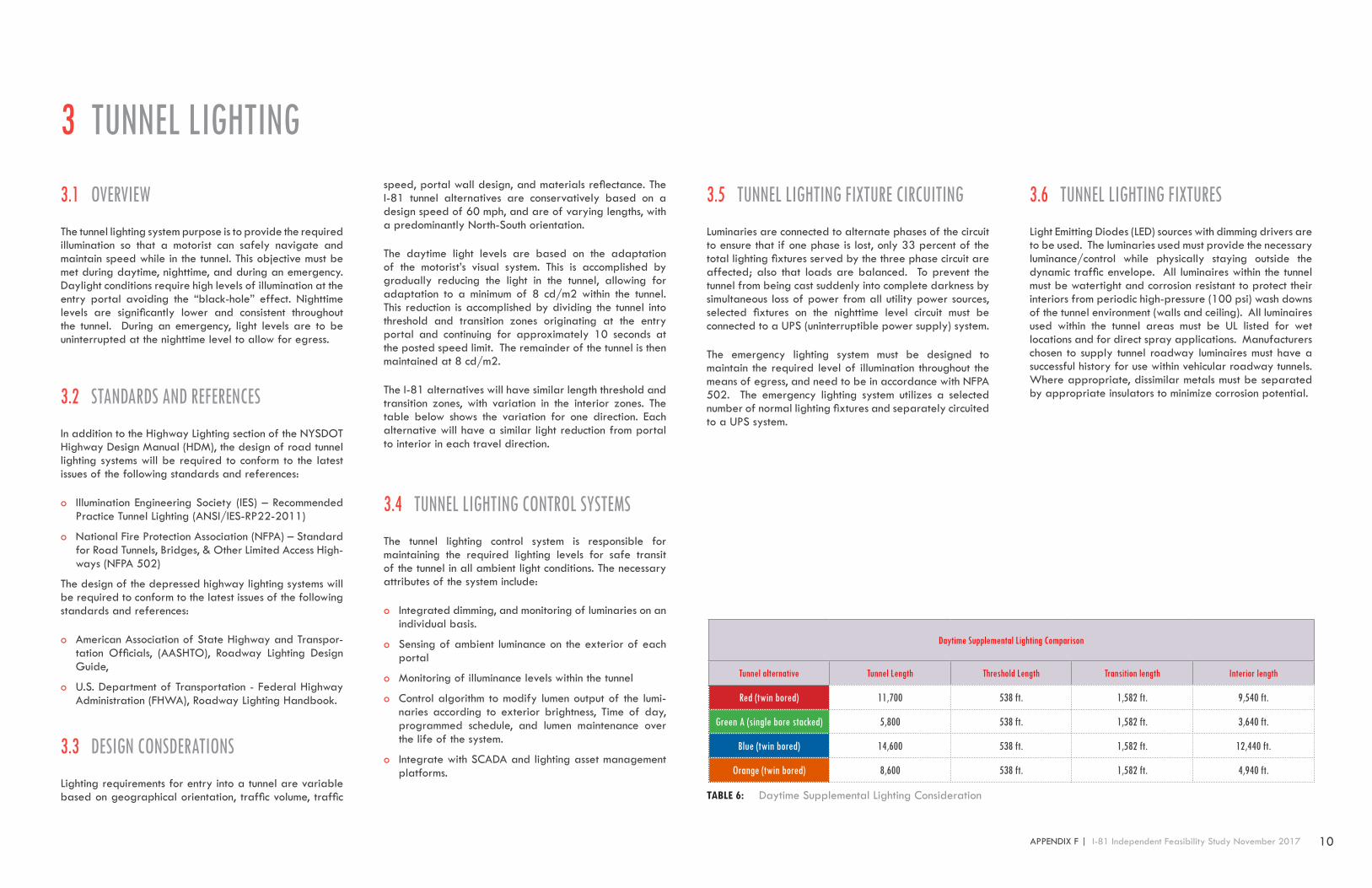
The daytime light levels are based on the adaptation of the motorist’s visual system. This is accomplished by gradually reducing the light in the tunnel, allowing for adaptation to a minimum of 8 cd/m2 within the tunnel. This reduction is accomplished by dividing the tunnel into threshold and transition zones originating at the entry portal and continuing for approximately 10 seconds at the posted speed limit. The remainder of the tunnel is then maintained at 8 cd/m2.
The I-81 alternatives will have similar length threshold and transition zones, with variation in the interior zones. The table below shows the variation for one direction. Each alternative will have a similar light reduction from portal to interior in each travel direction.
3.4 TUNNEL LIGHTING CONTROL SYSTEMSThe tunnel lighting control system is responsible for maintaining the required lighting levels for safe transit of the tunnel in all ambient light conditions. The necessary attributes of the system include:
o Integrated dimming, and monitoring of luminaries on an individual basis.
o Sensing of ambient luminance on the exterior of each portal
o Monitoring of illuminance levels within the tunnel
o Control algorithm to modify lumen output of the lumi-naries according to exterior brightness, Time of day, programmed schedule, and lumen maintenance over the life of the system.
o Integrate with SCADA and lighting asset management platforms.
3.5 TUNNEL LIGHTING FIXTURE CIRCUITINGLuminaries are connected to alternate phases of the circuit to ensure that if one phase is lost, only 33 percent of the total lighting fixtures served by the three phase circuit are affected; also that loads are balanced. To prevent the tunnel from being cast suddenly into complete darkness by simultaneous loss of power from all utility power sources, selected fixtures on the nighttime level circuit must be connected to a UPS (uninterruptible power supply) system.
The emergency lighting system must be designed to maintain the required level of illumination throughout the means of egress, and need to be in accordance with NFPA 502. The emergency lighting system utilizes a selected number of normal lighting fixtures and separately circuited to a UPS system.
Daytime Supplemental Lighting Comparison
Tunnel alternative Tunnel Length Threshold Length Transition length Interior length
Red (twin bored) 11,700 538 ft. 1,582 ft. 9,540 ft.
Green A (single bore stacked) 5,800 538 ft. 1,582 ft. 3,640 ft.
Blue (twin bored) 14,600 538 ft. 1,582 ft. 12,440 ft.
Orange (twin bored) 8,600 538 ft. 1,582 ft. 4,940 ft.
TABLE 6: Daytime Supplemental Lighting Consideration
3.6 TUNNEL LIGHTING FIXTURESLight Emitting Diodes (LED) sources with dimming drivers are to be used. The luminaries used must provide the necessary luminance/control while physically staying outside the dynamic traffic envelope. All luminaires within the tunnel must be watertight and corrosion resistant to protect their interiors from periodic high-pressure (100 psi) wash downs of the tunnel environment (walls and ceiling). All luminaires used within the tunnel areas must be UL listed for wet locations and for direct spray applications. Manufacturers chosen to supply tunnel roadway luminaires must have a successful history for use within vehicular roadway tunnels. Where appropriate, dissimilar metals must be separated by appropriate insulators to minimize corrosion potential.

11 I-81 Independent Feasibility Study November 2017 | APPENDIX F
3.7 TUNNEL EGRESS STAIRWELLS AND ANCILLARY SPACES
For tunnel emergency egress passageways and ancillary spaces, fixtures should be surface or pendent mounted and suitable for wet locations. Typically, such fixtures are provided with 1/8-inch thick acrylic lenses and utilize a 4000K LED source.
Egress passages must be designed for an average illuminance of 10 foot-candles (fc). Circuiting for cross passages and egress stairwells must be designed in accordance with requirements of the National Electrical Code. Although energized continuously, the luminaires need to be controlled in order to reduce energy consumption when spaces are unoccupied.
Exits within the tunnel need to be clearly identified by dedicated emergency exit lighting that lights the door and adjacent surfaces to a higher level than the interior of the tunnel, so as to provide the necessary level of demarcation. This exit lighting is in addition to the exit markings, strobe lights, and directional signs described in NFPA-502.
3.8 TUNNEL FIXED MESSAGE SIGN LIGHTINGAny ceiling mounted, non-internally illuminated signs that are required to be located in a road tunnel will need to be externally illuminated using either the luminance or illuminance methods in accordance with the following criteria:
Luminance* - 80 cd/m2 minimum
Illuminance - 40 fc (400 lux) minimum
* - 65 percent maintained reflectance
The maximum to minimum uniformity ratio on the sign face must not exceed 4 to 1. The maximum illumination gradient produced on the sign face should be 2 to 1.
Fixtures must be located so that they do not interfere with sign visibility for drivers of any type of vehicle.
3.9 APPROACH LIGHTINGThe illumination level for a tunnel approach roadway is based on the nighttime roadway level inside the tunnel. In accordance with ANSI/IES RP-22 the illumination level for the approach roadways must be equal to 1/3 that of the nighttime tunnel illumination levels, with an average to minimum uniformity not to exceed 3 to 1.

12 APPENDIX F | I-81 Independent Feasibility Study November 2017
4 TUNNEL FINISHES4.1 OVERVIEWEach of the road tunnel alternatives being considered herein for the I-81 Corridor will require consideration on the type and level of architectural finish elements that will be required and incorporated. These architectural finish elements can be categorized as follows:
o Highway Architecture, including approach roadway elements, retaining walls, U-wall sections, depressed roadway sections, and portals
o Interior tunnel elements including walls, ceilings, elevat-ed walkways and railings, equipment cabinets, signage, egress doors, and structural fireproofing
o Egress elements including corridors, cross passages, wheelchair areas, and egress stairs
4.2 CODES, STANDARDS & REFERENCESGuidance on the requirements and application of the ar-chitectural finish elements will be primarily provided and governed through the following documents:
o National Fire Protection Association (NFPA) 502, Stan-dard for Road Tunnels, Bridges, and Other Limited Ac-cess Highways
o National Fire Protection Association (NFPA) 101, Life Safety Code
o New York State Building Code, latest edition
o U. S. Occupational Safety and Health Administration (OSHA)
o American Association of State Highway and Transpor-tation Officials (AASHTO) – A Policy on Design Stan-dards-Interstate System (2016)
4.3 HIGHWAY ARCHITECTURE ELEMENTS
4.3.1 TUNNEL APPROACH AND TRANSITION ROADWAYS
Highway Architecture requirements for the tunnel approach roadway elements, U-wall, retaining wall, and depressed roadway section design include the following:
o Design integration of the retaining walls, U-walls, and U-wall battering with the overall project design criteria
o Coordination of lighting, lighting pilasters, and embed-ded utility cabinets with the overall section design
o Design and integration of U-wall rustication with the overall design
o Other ornamental graphics or elements; these can be project specific, reflective of the area’s history, or de-sired by the client or communities involved
4.3.2 ENTRANCE AND EXIT PORTALS
The portal design theme should be consistent with that of the overall architectural design and should emphasize common characteristics in order to:
o Maintain uniformity of perception in the driving expe-rience and visually ease the transition from U-wall sec-tion to tunnel;
o Maximize the tunnel recognition by the driver
o Coordinate with other disciplines (Mechanical, Electri-cal, Plumbing) to embed or otherwise conceal conduit, fireproofing, standpipes, etc., from the view of motorists
o Complement aesthetic of the U-wall sections and other tunnel ancillary structures
4.4 INTERIOR TUNNEL ELEMENTS
4.4.1 TUNNEL WALLS
Tunnel walls may be finished or unfinished. Finishes are directly influenced by the requirements of NFPA 502, Standard for Road Tunnels, Bridges, and Other Limited Access Highways. Section 7.3 of this standard requires protection of structural elements sufficient to withstand RWS (Rikswaterstaat) time-temperature curve conditions for 120 minutes. Protection options (discussed in detail below below) include spray or board fireproofing, integral plastic fibers, and sacrificial layers of concrete. Spray and board fireproofing may be exposed, painted, or covered with architectural panels to provide a more finished architectural appearance. Finished surface materials of these panels includes painted steel, aluminum, precast concrete, or ceramic tile. Wall systems need to accommodate elements from other disciplines such as equipment cabinets, penetrations of conduits, and signage. Wall finishes visible to the motorist should be washable and impervious to water intrusion, salt, and permanent staining from airborne particulates.
4.4.2 TUNNEL CEILING
Similar to the tunnel walls, NFPA 502 requires ceiling structures to be fireproofed. This is usually accomplished with spray fireproofing, board fireproofing, concrete with embedded plastic fibers and/or sacrificial layers of concrete cover. Ceilings usually do not receive elaborate finished architectural treatment like walls, and sometimes consist of exposed fireproofing painted uniformly black to disappear visually into the tunnel background. Ceramicoat paint has been used effectively for this purpose.
4.4.3 TUNNEL WALKWAYS
Walkways in tunnels can be at roadway level or elevated. While elevated walkways are preferred by first responders and tunnel maintenance personnel, the elevation makes egress by motorists more difficult, especially in the case of mobility impaired persons. At the
FIGURE 10: Construction Photo of Twin Bored Tunnel Portals and Approach Roadway Section
FIGURE 11: View of Bored Tunnel Showing Finish Features
Including traffic barriers, elevated walkway and railing, architectural wall panels, dark-painted ceiling fireproofing panels and utilities, and tunnel lighting fixtures
13 I-81 Independent Feasibility Study November 2017 | APPENDIX F
Central Artery project in Boston, MA, elevated walkways were desired by the Boston Fire Department since fighting fires from an elevated position was considered easier than from roadway level. In that particular case, the mobility impaired were required to wait for emergency personnel to assist them in accessing the elevated walkway. Elevated walkways serving the public require continuous 42” high railings, usually fabricated from stainless or galvanized steel. Wherever access to the elevated surface is desired, railings are interrupted and provided with grips on either side of the opening. Barrier faces receive toe holes at these locations. In tunnels where no railings are present, standalone toe-hole locations should be provided with vertical grips to facilitate access to the walkway.
4.4.4 TUNNEL EQUIPMENT CABINETS
Equipment cabinets for electrical, communications, fire protection, or other equipment should be fabricated from stainless steel. Locations, spacing, mounting heights, and penetrations of conduits and standpipes should be coordinated with the disciplines involved. Quick identification and easy access to these cabinets is extremely important in emergencies. Wall panel systems and fireproofing should be designed to seamlessly accommodate the cabinets. Cabinets that are surface mounted or project from the wall surface cannot reduce required walkway widths or intrude into the vehicular dynamic envelope. Cabinets can be open or closed boxes, and inclined cabinets with doors should be provided with hold open devices to prevent the doors from inadvertently slamming shut. Cabinets should be identified with appropriate signage, either with applied signage or signs immediately adjacent to the cabinet.
4.4.5 TUNNEL SIGNAGE
Signs for approach roadway sections, U-wall sections and tunnels should be as simple, visible, and legible as possible. They can be provided for either motorists or for tunnel personnel and first responders. Signage should be consistent over the length of the tunnel and open U-wall sections, and should complement the highway signage and other finished architectural elements in the tunnel. Signage may be fabricated from porcelain enamel steel, silkscreened aluminum, applied vinyl, or other approved materials. Where possible, anchoring should be concealed.
4.4.6 EMERGENCY EGRESS DOORS
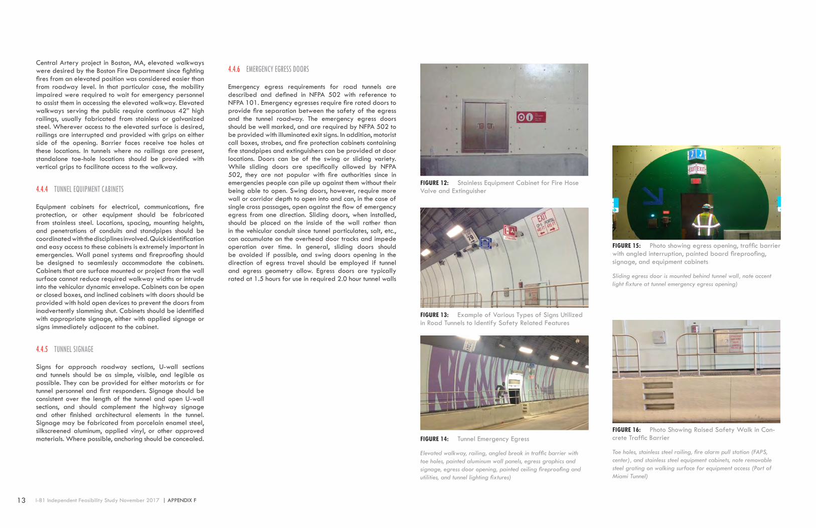
Emergency egress requirements for road tunnels are described and defined in NFPA 502 with reference to NFPA 101. Emergency egresses require fire rated doors to provide fire separation between the safety of the egress and the tunnel roadway. The emergency egress doors should be well marked, and are required by NFPA 502 to be provided with illuminated exit signs. In addition, motorist call boxes, strobes, and fire protection cabinets containing fire standpipes and extinguishers can be provided at door locations. Doors can be of the swing or sliding variety. While sliding doors are specifically allowed by NFPA 502, they are not popular with fire authorities since in emergencies people can pile up against them without their being able to open. Swing doors, however, require more wall or corridor depth to open into and can, in the case of single cross passages, open against the flow of emergency egress from one direction. Sliding doors, when installed, should be placed on the inside of the wall rather than in the vehicular conduit since tunnel particulates, salt, etc., can accumulate on the overhead door tracks and impede operation over time. In general, sliding doors should be avoided if possible, and swing doors opening in the direction of egress travel should be employed if tunnel and egress geometry allow. Egress doors are typically rated at 1.5 hours for use in required 2.0 hour tunnel walls
FIGURE 15: Photo showing egress opening, traffic barrier with angled interruption, painted board fireproofing, signage, and equipment cabinets
Sliding egress door is mounted behind tunnel wall, note accent light fixture at tunnel emergency egress opening)
FIGURE 16: Photo Showing Raised Safety Walk in Con-crete Traffic Barrier
Toe holes, stainless steel railing, fire alarm pull station (FAPS, center), and stainless steel equipment cabinets, note removable steel grating on walking surface for equipment access (Port of Miami Tunnel)
FIGURE 12: Stainless Equipment Cabinet for Fire Hose Valve and Extinguisher
FIGURE 13: Example of Various Types of Signs Utilized in Road Tunnels to Identify Safety Related Features
FIGURE 14: Tunnel Emergency Egress
Elevated walkway, railing, angled break in traffic barrier with toe holes, painted aluminum wall panels, egress graphics and signage, egress door opening, painted ceiling fireproofing and utilities, and tunnel lighting fixtures)

14 APPENDIX F | I-81 Independent Feasibility Study November 2017
4.4.7 STRUCTURAL FIREPROOFING
Protection of tunnel structural elements is required by NFPA 502. Fireproofing should be coordinated with other engineering disciplines, and the Tunnel Finishes designer should assist as necessary in the processes of development of a hazard analysis, selection of fire protection systems, consultation with the AHJ on fire life safety issues, and integration of various fire protection systems, including fire suppression systems, into a comprehensive tunnel operation and emergency response plan. Options for fireproofing can include sacrificial layers of spray or board applied directly to the surface of the structure of the vehicular portions of the tunnel, or plastic fibers integral to the actual concrete structure, or layers of additional sacrificial concrete. The protection is seldom seen as a finished material in its own right, and should be complemented with an overall aesthetic architectural program including finished wall panels and painting of fireproofing, as appropriate.
The following presents advantages and disadvantages of the two most commonly used options for structural fireproofing in tunnels that should be considered, spray versus board versus concrete additives:
Spray fireproofing advantages:
o Effective, widely used fireproofing system
o Known technology
o Easy Installation, minimum detailing required
o Fast application
o Multiple suppliers; easier than board to obtain com-petitive bids
o Initial installation is more finished and uniform appear-ing than board
Spray fireproofing disadvantages:
o Extremely susceptible to de-bonding from water infil-tration
o Requires a steel mesh anchored to substrate to enhance bonding
o Thicker dimensions required for fire ratings than board
o Poor performance at construction and expansion joints
o Masks structural defects; cracks do not generally tele-graph through coating which makes defects more diffi-cult to locate and fix
o Requires replacement when liner is inspected
o Rough surface discolors quickly
o Difficult to wash
o When areas are replaced, difficult to visually match surrounding areas
Board fireproofing advantages:
o Effective replacement for prior asbestos fireproofing – low thermal conductivity
o Relatively easy Installation
o More easily removed and replaced for tunnel liner in-spection than spray
o Unaffected by water infiltration
o Leaks easier to detect and locate than spray
o Low maintenance cost
o Hard smooth finish; washable
o Can be installed to match construction and expansion joints
o Can be installed as part of the formwork of the con-crete liner (lost formwork)
o Does not always require replacement after fire event
o Does not require specialized equipment to install
Board fireproofing disadvantages:
o More difficult application than spray
o More detailing required than spray
o Difficult to apply to tight radius tunnel geometries, al-though the use of two layers of thinner material with staggered joints can be used to fit to tighter curves
o Very few manufacturers; and only Promat, a Belgian product, has extensive history of use in the USA
o Unfinished appearance, with many fasteners and seams visible, but can be painted-Ceramicoat has been used successfully
Fire resistant concrete advantages:
o No additional fireproofing is required; less labor and shorter completion time
o Layer of concrete with fibers is good for the entire ser-vice life of the tunnel
o Unrestricted access for tunnel inspection
o Unaffected by water seepage
o Can reduce spalling at unprotected areas
Fire resistant concrete additives disadvantages:
o Can add up to 10” of thickness to the ceiling and walls being protected
o Fibers make concrete very stiff and difficult to work, and potentially porous
FIGURE 17: Stainless Steel Sliding Egress Door
Applied vinyl signage, internally illuminated exit sign, and stainless steel screen at cross passage between two bored tunnel elements (Port of Miami Tunnel)Toe holes, stainless steel railing, fire alarm pull station (FAPS, center), and stainless steel equipment cabinets, note removable steel grating on walking surface for equipment access (Port of Miami Tunnel)
FIGURE 18: Construction Photo Showing Stainless Steel Sliding Egress Door inside Egress Corridor
Open track, vinyl adhesive signage, and stainless steel counter-weight box (Midtown Tunnel, Virginia))

15 I-81 Independent Feasibility Study November 2017 | APPENDIX F
4.5 TUNNEL EMERGENCY EGRESSEmergency egress requirements from road tunnels are established in NFPA 502 which also invokes applicable references NFPA 101, Life Safety Code. Depending on the configuration of the tunnel facility, emergency egress elements may include fire-rated doors, escape corridors, cross passage ways, and/or egress stairways. NFPA 502 requires emergency exits spaced at a maximum distance of 1000’ (300m). Where egresses are used to provide escape from the incident to a non-incident tunnel such as a cross passageway the spacing requirements are reduced with typical distances between exits in the order of 600’ (183m). The minimum egress path width is 3.7’ (1.12m). Fire rated doors are required to separate the egress pathway from the tunnel. Sliding egress doors are typically used for cross passageways to allow for bi-directional egress travel. Suitable emergency signage, lighting, and pressurization are also required.
Options for the arrangement of emergency exits in road tunnels varies based, primarily, on the tunnel configuration. For the tunnel alternatives considered herein, the following are the most likely options for emergency egress:
4.5.1 SINGLE BORE STACKED TUNNEL OPTION
In a single bore stacked tunnel, each roadway level can provide an egress pathway to safety in the other (non-incident) traffic level. To accommodate for this, stairway egress connections between the two traffic levels are necessary. The stairways are can be configured within the ancillary space at the side of the bore. The space must be provided with fire rated doors to separate it from the roadway at each traffic level and configured to allow space where non-ambulatory persons can wait for rescue personnel. The stairways are required to be fire rated and pressurized. An egress corridor can also be provided; however, in a twin deck tunnel there may not be sufficient lateral space for this solution, and connecting stairs may be the only option.
4.5.2 DOUBLE BORED TUNNEL OPTION
In a double bore version, twin parallel bores are placed adjacent to each other, with mined cross passages provided between them at intervals. As in the stacked single bore option, each vehicle conduit can provide an egress pathway for an incident in the other conduit. No
parallel egress corridors are required. If the twin bores cannot be constructed at the same level, short lengths of stairs are required. In these cases, areas for wheelchairs or non-ambulatory persons are required.
FIGURE 19: Stacked Single Bore Tunnel with Intercon-necting Egress Stairs (Seattle Tunnel, WA)
FIGURE 20: Twin Bored Tunnel Configurations with Cross Passages (bores can be at the same level or different levels (WSP USA renderings))
FIGURE 21: Cross Passage between Two Bored Tunnels Showing sliding door (open at far end), illuminated exit sign, equipment cabinets, pressurization fans, and emer-gency lighting fixtures (Port of Miami Tunnel)
FIGURE 22: Cross Passage between Two Bored Tunnels (showing sliding door (open at far end), illuminated exit sign, equipment cabinets, pressurization fans, and emer-gency lighting fixtures (Port of Miami Tunnel))
FIGURE 23: Rendering of Single Bore Stacked Tunnel Option
Tunnel roadway wall removed to show egress stair configuration beyond (WSP USA rendering)

16 APPENDIX F | I-81 Independent Feasibility Study November 2017
5 ELECTRICAL SYSTEMS5.1 OVERVIEWEach of the tunnel alternatives identified herein for the I-81 Corridor through Syracuse will require a variety of electrical systems to support safe traffic operation. The required installation methods and performance criteria of these various electrical systems for road tunnel application have been generally defined in within applicable codes and standards including NFPA 502 and the National Electrical Code. The required tunnel electrical systems include:
o Power Distribution
o Fire Alarm and Detection
o Emergency Communications
o Security
o Supervisory Control and Monitoring (SCADA)
5.2 POWER DISTRIBUTION SYSTEMRoadway tunnels typically are provided with redundant, reliable and robust electrical power supplies and power distributions systems. These same power requirements will be apply to each of the I-81 tunnel alternatives being considered herein. Specific aspects of the electrical power distribution system requirements are as follows.
5.2.1 REDUNDANT SUPPLIES
Power for the tunnel systems is usually supplied from two independent incoming medium voltage supplies, designated ‘A’ and ‘B’, each capable of supporting the entire electrical load, but normally supporting approximately 50% of the total electrical load. These ‘A’ and ‘B’ supplies typically are taken from each portal end local electrical utility distribution network respectively, to minimize the risk of common point failure.
5.2.2 LOAD SPLITTING
The total electrical load, including the lighting and ventilation systems, is then split approximately 50/50 between the ‘A’ and ‘B’ supplies so that if one supply fails, only 50% of the system capacity will be initially (momentarily) disrupted.
5.2.3 CABLE SEGREGATION
Cabling, transformers and switchgear associated with ‘A’ and ‘B’ supplies are usually physically segregated to the maximum practicable extent.
5.2.4 ALTERNATIVE SUPPLIES
If either supply should fail, or equipment needs to be temporarily taken out of service for inspection, maintenance or repair, provisions are also made for the whole of the tunnel electrical load to be transferred to the alternative supply until normal operation can be restored.
5.2.5 SWITCHGEAR CABLING
Switchgear controlling interconnecting cables between the ‘A’ and ‘B’ substations is interlocked to prevent through feeding between the portal local electrical utility distribution supply networks.
5.2.6 SECONDARY DISTRIBUTION SYSTEM
The secondary distribution systems in the United States typically operate at 480Y/277 Volts, in a main-tie-main configuration utilizing double–ended switchgear, electrically interlocked to prevent paralleling.
5.2.7 STANDBY POWER SYSTEMS
Standby power systems are also a standard implementation for roadway tunnels and consist of standby generators, switchboards, transfer switches, fuel supply and storage, accessories, and wiring as required to provide standby power to the following loads, usually as a minimum:
o Selected tunnel, utility room, egress corridor and egress stair lighting*;
o Tunnel drainage system;
o Storm water pump stations;
o Fire protection pumps;
o Minimum tunnel ventilation (25% of installed capacity);
o DMS and LUS equipment*;
o Communications such as radio, telephone, supervisory control and data acquisition (SCADA), and fire detec-tion and alarm systems*;
o CCTV and incident detection;
o Selected building lighting*;
o Selected receptacles in fire cabinets, switchgear rooms, generator rooms, mechanical rooms, control rooms, rest rooms, stairways, maintenance shops, and offices.
* - Systems usually are also provided with battery-supported UPS for which standby power will provide long term back-up.
Standby power system design is based upon ANSI/IEEE Standard 446 and the elements defined herein. UPS units are connected to draw power from a standby source if normal power fails. Standby generators typically are located in or at the buildings at each end of the tunnel. Standby power switchboards may be located in the same room as the generators, and such room is provided with adequate ventilation and relatively dust free air. Transfer switches are located where it is most advantageous based upon access for operation, economic reasons, and other governing factors.
5.2.8 STANDBY GENERATOR UNITS
Standby generators are typically diesel engine-driven. Generator output is at 480/277 Volts, 60 Hertz, three phase, four wire, compatible with secondary distribution system. In general, one standby generator at each building should be sufficient to supply the load. If two or more standby generators per building is required, consideration is usually given to the advantages and disadvantages of parallel operation.
Another fuel source option is natural gas from the local utility system, and may be considered as the emergency fuel source in lieu of diesel, if acceptable to the AHJ. Regardless of fuel type, if storage tanks are used, sufficient tank storage or continuous commercial fuel supply (such as natural gas) is typically provided at each location to support a determined period of continuous operation, including a certain time period under emergency loading. Storage tanks must conform to all regulations that pertain and are in force in the local jurisdiction and the entire system must conform to NFPA 30 and NFPA 37.
The loss of normal power at the automatic transfer switch causes the associated standby generator(s) to start up automatically and assume the load if the normal power interruption continues. Loads may also be arranged for sequential starting if required, based on capacities available
5.2.9 STANDBY SWITCHBOARDS
480/277 Volt standby switchboards are indoor type, metal-enclosed, and are self-supporting structures. Switchboards usually utilize compartmentalized design with individually mounted devices in the distribution sections.
17 I-81 Independent Feasibility Study November 2017 | APPENDIX F
5.2.10 UNINTERRUPTIBLE POWER SUPPLIES (UPS)
UPS units provide uninterruptible electrical power to designated loads. The following are typical loads that are connected to UPS systems:
o DMS, LUS, CCTV and automatic incident detection equipment;
o Communications, supervisory control and data acquisi-tion system, and fire detection and alarm systems;
o Selected tunnel, utility room, egress corridor and egress stair lighting;
o Selected building lighting;
The UPS units are designed to operate “on line” such that when normal power fails, the batteries will provide power for a designated period through the inverter output. If a UPS malfunctions, a static switch automatically connects the load directly to the normal supply while simultaneously opening the inverter-output circuit breaker. A maintenance by-pass is typically provided to manually transfer the load to the normal supply for routine service or maintenance of the UPS.
5.2.11 ELECTRICAL CIRCUIT CONDUCTORS (CABLE)
All sub-main and final sub-circuit conductors within the tunnel road space are protected from fire, either by the use of fire rated cables adhering to NFPA 502 as appropriate, or by being enclosed within fire protected ducts. All cables buried in the ground or passing through the structure are typically enclosed in ducts, with 25% spare ducts left empty for unspecified future use. Where it is not possible to obtain suitable fire rated versions of exposed cables required for instrumentation, data transmission or communications equipment in the tunnel, resilience to fire is provided by alternate means, such as duplication by alternate routing. Final connections to equipment that will be not be expected to continue operating under direct impingement of fire may be made in cables with fire rating similar to that of the equipment served. In such instances suitable precautions are taken to ensure the continued functioning of equipment not directly involved in the fire.
5.3 FIRE ALARM AND DETECTION SYSTEMSRoadway tunnels and supporting facilities are required to be provided with fire alarm and detection systems in compliance with NFPA 502 and 72. Road tunnels are typically provided with manual pull stations for motorist use that located along the roadway at intervals complying with NFPA 502. The tunnel may also require a heat detection system capable of monitoring the traffic lanes. When utilized, roadway area the heat detection systems are typically a subsystem to the main fire alarm control panel.
Tunnel support buildings and other ancillary areas such as pump rooms or equipment rooms must also be provided with a means of automatic fire detection such as heat and smoke detectors. Annunciation of a fire condition in the ancillary space is typically through horn/strobes.
The main Fire Alarm Control Panel (FACP) used for a road tunnel facilities is typically an addressable type so that the location of each device within the facility can be readily identified. In road tunnels where a fixed fire suppression systems are used, the systems activation controls are often interfaced with the tunnel fire detection systems via the FACP.
5.4 EMERGENCY COMMUNICATION SYSTEMSRoadway tunnels are typically provided with an emergency telephone system, with telephones located throughout the tunnel, for motorist use in case of vehicle breakdown or other emergency situation. The emergency telephones directly connected to the Operations Control Center and are designed so that an intelligible conversation can take place with background noise from traffic in the tunnel and the tunnel ventilation system.
The telephone system typically is served by two separately located telephone controllers. Each controller serves alternate telephones so that every other phone will be operational if one controller becomes disabled.
The Operations Control Center personnel usually is able to hold calls from, or call back to, any individual telephone on the system.
Radio rebroadcasting systems usually are also provided to maintain radio coverage in the tunnel of all channels required by the First Responders.
Commercial AM/FM radio rebroadcast systems may be installed in the tunnel, with Operations Control Center personnel override capability, to interrupt broadcasts with messages from the operators in case of emergency situations. This system can also be integrated with Highway Advisory Radio (HAR) messages to be broadcast within the tunnel.
Tunnels may also incorporate mobile telephone coverage within the space for uninterrupted motorist cell phone usage. This is typically accomplished by providing suitable space and UPS power supplies to enable third party cell phone service providers to install their equipment and antennas to give full coverage of all mobile telephone networks available in the tunnel.
5.5 SECURITY SYSTEMSRoadway tunnels, their supporting buildings and facilities are typically provided with integrated security systems that are comprised of access control, intrusion detection and CCTV subsystems for monitoring of the facilities and preventing unauthorized access to the site, buildings and critical infrastructure spaces.
The perimeter of all areas around the tunnel portals, the Tunnel Support Buildings and the Operations Control Center are monitored to detect and alarm any unauthorized intrusion. An alarm is raised at the Operations Control Center through the SCADA Operations Control Center Interface with details of the location and time when an intruder is detected.
Security lighting and a CCTV surveillance system is provided to give full coverage of these areas and to enable the movements of intruders to be viewed and tracked.
An access control system is provided to cover designated entry points to restricted areas and buildings. The system is usually designed to permit only authorized vehicles and personnel to enter, and automatically log all movements in and out of the secure areas.
Every designated entry point is typically provided with a telephone link to the Operations Control Center, accessible from both sides of the door or gate, to enable users to request assistance.
The Operations Control Center personnel is provided with the means to override the control of individual entry points in abnormal circumstances, to allow free access by First Responders, maintenance and construction personnel.
A means of locally unlocking and locking access gates and doors is also provided for use in the event of system failure.
A Surveillance Closed Circuit Television (CCTV) system is typically provided to allow surveillance coverage of the facility and all controlled access areas, as described above.
5.6 SUPERVISORY CONTROL, MONITORING AND DATA ACQUISITION (SCADA) SYSTEM
A comprehensive supervisory control and data acquisition (SCADA) system will be necessary for any of the tunnel alternatives being evaluated herein to permit monitoring and controlling of key systems and equipment throughout the facility, including any remotely located equipment or facilities, from the dedicated tunnel control center. The architecture of the SCADA system employs a fail-safe topology. Each programmable logic controller (PLC) is designed with a redundant “hot-standby” configuration, capable of seamless transfer of data upon failure of the main processor. Additionally the programmable logic controller is usually equipped with redundant power supplies.
The SCADA system employs a universal remote input/output network protocol, allowing different network devices the ability to communicate with the programmable logic controller. Remote input/output (RIO) cabinets are distributed throughout the facility in order to minimize hardwire cable runs between field devices and the SCADA system. Each remote input/output cabinet is typically designed to accommodate the required number of points for the digital input (DI), digital output (DO), analog input (AI), and other data modules as needed.

18 APPENDIX F | I-81 Independent Feasibility Study November 2017
Major mechanical and electrical equipment incorporate provisions for communication, control, and indication, via normally-open and normally-closed contacts, transducers, and auxiliary relays, or serial or IP Ethernet based communication, to provide control/indication to the SCADA system. System consists of communications networks, servers and operator interfaces. The communications network usually consists of dual fault tolerant, redundant fiber optic ring topology with management switches at each node.
Servers provided operate on a hot standby basis. Operator interfaces are typically provided at a dedicated remote operator control center and local to the tunnel, with different levels of system access protected by password for “guest”, “operator”, “supervisor” and “engineer”. The system also handles and manages data logging and transfer for alarms, alerts and record keeping for historical purposes.
5.7 TRAFFIC CONTROLRoadway tunnels are required by NFPA 502 to be provided with a means for control of traffic within the tunnel, as well as traffic on the approach roadways leading into the tunnel These systems are necessary to control traffic within the tunnel and/or to prevent vehicles from entering the tunnel in the event of an traffic incident or emergency and also for purposes of tunnel maintenance. Traffic control systems will be required for each of the I-81 tunnel alternatives being considered herein. The types of traffic control systems and devices likely to be required for any of these tunnel alternatives are described below.
5.7.1 INCIDENT IDENTIFICATION
An intelligent, programmable, CCTV video stream based Automatic Incident Detection (AID) system within the tunnel and its immediate approaches is usually provided. The automatic incident detection system provides the following facilities:
o Traffic speed and flow data;
o Detection and alarm for a single stationary vehicle in the tunnel;
o Detection and alarm for congested traffic flow in the tunnel;
o Detection and alarm for congested traffic flow down-stream of the tunnel; and
o Detection and alarm for a vehicle traveling in the wrong direction within or approaching the tunnel.
5.7.2 CLOSED CIRCUIT TELEVISION (CCTV)
A CCTV system for tunnel and approach roadways is provided for general surveillance purposes to enable the tunnel operator to view any part of the tunnel interior, emergency escape routes and approach roadways. Generally cameras will have pan, tilt and zoom (PTZ) capability.
Cameras are positioned so that if one camera fails, full coverage of the tunnel interior may be obtained by the use of the adjacent cameras on either side. SCADA system interfaces allow the nearest camera to an alarm event to be displayed automatically at the local tunnel operator control center through the use of presets. The alarm event is captured through an automatic real time recording feature for at least two cameras capturing alarm events simultaneously. The tunnel operator typically is able to manually start and stop the recording feature.
Each camera image usually also has an informational banner with identification, location, date and time in universal time coordinated format.
At a dedicated tunnel operations control center, there are typically multiple monitors and recording facilities to assure adequate redundancy in the system. One or more screens cycle all the cameras at least once every 60 seconds, while at least one of the other displays a single picture selected by the tunnel operator as a “spot” monitor. Systems are scalable and expandable to allow future addition of cameras or monitors.
5.7.3 DYNAMIC (VARIABLE) MESSAGE SIGNS (DMS)
Full matrix signs typically are provided in the tunnel and tunnel approaches at regular intervals above the travel lanes to display instructions and emergency messages to motorists. The signs are typically based on arrays of white LEDs on a black background, visible in bright sunlight and dimmable to suit the full range of ambient lighting conditions. Sign messages are remotely programmable by the tunnel operators.
5.8 TYPICAL DYNAMIC MESSAGE SYSTEM
5.8.1 LANE USE/CONTROL SIGNALS (LUS/LCS)
Signals are typically located along the tunnel walls or ceiling, and over the roadway at the tunnel portal approaches, at regular intervals to indicate the status of each travel lane as either opened or closed, through the use red and green symbols on black background suitable for the full range of ambient lighting conditions where located. Each signal head is independently controlled to indicate the status of each lane and is fully interlocked to prevent any possible conflicting indications, with fault conditions at a signal head to show a blank face. Signal heads are typically double aspect light emitting diode (LED) displays suitable for use with bidirectional traffic, as required. Traffic stop signals are provided to close the tunnel and prevent vehicles from entering in the event of an emergency.
5.8.2 OVER-HEIGHT VEHICLE DETECTION/PROTECTION (OVD)
The OVD system detection height is based on AASHTO required vertical clearance within the tunnel. The OVD system locates receiver/transmitter pairs along the roadway, outside of the tunnel entrance portals on approach roadways, such that the paths between each transmitter-receiver pair are parallel such that the beams between the pairs define a plane parallel to the detection height.
The OVD system operates in conjunction with DMS, LUS/LCS and CCTV components. In the event of an interruption of the beams crossing the roadway in the appropriate sequence, the detector controller activates downstream messages, and an audible alarm and strobe light warns the driver of the over height vehicle condition, and provides instructions to stop at a predetermined safe area and not enter the tunnel. An alarm is also generated to the tunnel operator.
FIGURE 24: Tunnel Incident Viewed on Closed Circuit Television System
FIGURE 25: Dynamic (Variable) Message Signs (DMS)
FIGURE 26: Typical Lane Use Signals

19 I-81 Independent Feasibility Study November 2017 | APPENDIX F
6 TUNNEL DRAINAGE SYSTEMS6.1 OVERVIEWTunnel drainage systems normally consist of two independent systems; a storm water control system and a tunnel drainage system.
Storm water control systems are required at the tunnel portals to intercept storm water flows that accumulate on the open approaches and transition roadways leading into and out of the tunnel. These portal drainage systems are necessary to collect and discharge storm water before it has a chance of entering the tunnel. The approaches may be partially of fully covered to minimize accumulation, and also for other purposes.
A separate tunnel drainage system, designed to be independent of inflow from sources outside the tunnel, is required to collect and discharge water and effluents generated within the tunnel. These effluent flows result from tunnel washing, use of fire suppression systems, vehicle carryover, and normal groundwater seepage. The tunnel drainage system must also be designed and equipped to accommodate a potential fuel spill. The profile of the selected tunnel alignment will dictate the location the tunnel drainage pumping station(s) as the drainage collection needs to occur at the lowest point(s) in roadway profile.
6.2 APPLICABLE STANDARDS The following standards and guidelines serve as the basis for the design of the tunnel and portal drainage systems:
o National Fire Protection Association (NFPA) 502 – Standard for Road Tunnel, Bridges, and Other Limited Access Highways
o Federal Highway Administration, Highway Engineering Circular (HEC) 12 – Drainage of Highway Pavement
6.3 DRAINAGE SYSTEM DISCHARGE CONSIDERATIONS
The storm water collected at the tunnel portals is considered to be clean and therefore does not require special treatment prior to discharge. However, the tunnel drainage effluent can be considered to consist of water contaminated with tunnel washing detergents, particulates, potentially saline infiltration water, and minor oily waste that are required to be connected to a municipal sanitary or industrial wastewater sewer system and may require some form of pre-treatment prior to discharge depending on local permitting requirements.
6.4 DRAINAGE SYSTEM CAPACITY BASISThe portal area storm water drainage systems should be designed to collect and discharge storm water based upon the duration and intensity of an established storm event for the geographical location, typically 50-year storm event. This system will be at a higher elevation that the low point tunnel drainage system, and can potentially drain by gravity into the city sewer system.
The low point tunnel drainage system(s) should be designed to collect and discharge effluent based on a capacity equal to the expected tunnel seepage plus the flow of wash-down water or fire protection systems; whichever is the largest. The following provides guidance on establishing tunnel drainage system capacity:
o The quantity of water resulting from tunnel washing can vary in the range of 150 to 500 gpm depending on the maintenance equipment used.
o Water inflow from a fire-fighting event is determined from the fire protection system design flow.
o Generally in the case of a fuel spill, the drainage system pumps must be shut down so as to contain the spill within the pump station in order that it may be collected and legally disposed of as hazardous
material. Therefore, the pump station well(s) must be designed with adequate storage.
o Normal anticipated amounts from structural seepage (< 1 gallon/minute/1,000 feet of tunnel) and rain water carried in by vehicles are likely to have no impact on design capacities.
6.5 DRAINAGE SYSTEM PIPINGThe drainage collection systems used both inside the tunnel and along the open portal area transition and approach roadways will typically consist of cast iron grated drop inlets designed for 20 ton truck loading (HS-20), positioned outside of the travel lanes and spaced at intervals that will allow for cleaning between inlets. The drop inlets will connect to a drainage main embedded below the roadway surface that will use the roadway profile to convey effluent by gravity to either the city storm water system (where possible for portals) or to the associated pump station by gravity. Where possible, maintaining a minimum super elevated cross-slope of 1 percent will eliminate the need to provide inlets on both sides of the roadway.
6.6 DRAINAGE SYSTEM PUMPS AND PUMP STATIONS
Where required, portal area pump stations are likely to be of a significantly larger capacity than that of the tunnel low point pump station(s) and commonly require vertical turbine type pumps whereas tunnel low point pump stations are commonly designed with centrifugal type pumps which require much less overall space.
Bored tunnels such as those considered for the I-81 tunnel alternatives allow sufficient space below the roadway, within the tunnel lining, for locating the tunnel low point pump station(s). The profile of the tunnels has been developed to ensure only one low point, and associated pump station, between portals.
For both the portal and tunnel drainage systems pumps should be sized so that adequate capacity is available should any one pump be out of service due to planned or unplanned maintenance/repair. Pump stations should be designed to for automatic operation with the local pump control panel linked to communicate operational data/equipment status remotely to a tunnel operator. Since the potential exists for collection of petroleum based fuels and oils within the tunnel drainage system, the tunnel drainage pump station(s), including all components and equipment, must be designed to comply with the requirements of the National Electrical Code (NFPA 70) for a Class I, Division II type hazard location. A hydrocarbon monitoring system is required within the tunnel drainage pump stations to detect unsafe vapor levels.

20 APPENDIX F | I-81 Independent Feasibility Study November 2017
7 TUNNEL OPERATIONS AND MAINTENANCE7.1 OVERVIEWA dedicated and well planned tunnel operations and maintenance program is necessary to ensure a safe, well maintained, and reliable tunnel facility which maximizes public safety and roadway availability. Each of the various tunnel alternatives discussed in this report has an inherent requirement for a tunnel Operations and Maintenance Plan that fully considers the future operations and maintenance needs of the facility and adequately identifies all ancillary facilities, operating systems, infrastructure, staffing, maintenance equipment, and related items necessary to operate and maintain the facility.
Ancillary facilities that will be required to support operation of the tunnel alternatives considered herein will include provision of a dedicated operation and control center for tunnel operations staff who will be responsible for the operation and monitoring of the mechanical, electrical, and traffic control systems in response to various conditions and incidents.
For major road tunnel facilities similar to those considered herein, tunnel operators will be required to staff the operations control center on a 24/7/365 basis. The tunnel operations function may also include incident response capabilities such as patrol personnel who are available to provide assistance to disabled motor vehicles and provide towing services in order to quickly respond to disabled vehicles in order to mitigate impact to traffic and the potential of a more significant incident.
Maintenance related facilities may include maintenance shops, garage facilities, and other storage spaces to house equipment and spare parts that are needed to maintain the tunnel. The majority of the required maintenance may be performed during normal business hours however some level of maintenance staff need to be available 24/7 to respond to unplanned issues. Most in-tunnel maintenance activities need to occur during planned tunnel/lane closures during off-peak traffic hours. Appropriate maintenance requires a mix of personnel including electricians, mechanics/millwrights, and general maintenance staff to
maintain the facilities and various systems, support traffic control measures and respond to traffic incidents.
A significant level of planning and coordination is required to operate and maintain a major road tunnel facility in a manner that will properly ensure the safety and protection of the motorists while minimizing traffic disruptions. An Operations and Maintenance Plan consisting of a compilation of the various incident and emergency management plans, maintenance management plans, operational procedures, and established protocols determined to be necessary to the safe and efficient operation and maintenance of the tunnel facility.
7.2 OPERATIONS & MAINTENANCE PLANThe Operations and Maintenance Plan is a critical document used for the immediate and future planning of operational budget, staffing needs, and equipment requirements that support the operation of the tunnel facility as related to functionality and maintainability. The O&M Plan sets the course of direction for a variety of activities and identifies schedules. A well-developed Operations and Maintenance Plan will:
o Identify all of the key sub plans, procedures, and other documents that define how the facility and personnel are expected to operate.
o Identify the organizational staff plan requirements including staff positions, qualifications, locations, and work hours
o Identify the organizational policies, and procedures for hiring and training of staff
o Identify the types of facilities and fleet vehicles need-ed.
o Identify the tools, equipment, consumables, spare equipment and spare parts needed.
o Identify any subcontracts necessary for services that are to be performed by subcontractors.
o Identify incident response staff and patrol vehicles
o Identify all of the functions, procedures and manuals necessary to operate and maintain the project.
The Operations and Maintenance Plan should consist of several sub-plans and related documents that will serve to describe the various policies and specific procedures for proper operations and maintenance of the tunnel facility. The hierarchy of a representative Operations and Maintenance Plan is as follows:
Project Management Plans
o Safety Plan
o Security Plan
o Environmental Management Plan
o Emergency Response Plan
o Organization and Staffing Plan
o Budget Plan
Operations and Maintenance Plan
o Operations Manual
o Operating Procedures o Incident Response Plan & Procedures
o Maintenance Manual
o Asset Management Plan o Computerized Maintenance Management System
(CMMS) o Maintenance Plans o Maintenance Procedures
During the planning and feasibility stage of a major urban road tunnel project such as the I-81 corridor it is important to consider the Operations and Maintenance Plan so the facility design accounts for all of the facilities, infrastructure and other items needed to support the proper functionality an operation of the facility. The development of a Concept of Operations Report is the first step to developing the basis of the Operations and Maintenance Plan as a Concept of Operations is necessary to outline a basic understanding of how the facility must function in relation to the overall
road and traffic network and identifies the individual agencies, entities and other stakeholders dependent on the overall successful operation of the facility and defines the roles and responsibilities of each.
7.3 CONCEPT OF OPERATIONS
7.3.1 PURPOSE
The Concept of Operations is an umbrella document that provides a high-level definition of overall “traffic corridor”, in this case I-81 through Syracuse, the expected traffic operational performance, strategies, and the responsibilities of individual agencies and entities. A Concept of Operations Report should include the following sections:
o Description of Project and Facilities
o Stakeholders
o Corridor Operations Activities
o Tunnel Systems and Operations Activities
o Incident Response and Emergency Response
The following paragraphs briefly explain the purpose of each of these sections in order to demonstrate the content and the importance to this document.
7.3.2 DESCRIPTION OF PROJECT AND FACILITIES
This section of the Concept of Operations Report will provide an overview description of the tunnel facility including all ancillary facilities such as control rooms, support buildings, maintenance shops, and the various mechanical, electrical and traffic control systems necessary to provide safe operation of the tunnel and related facilities. It should also define how the tunnel will operate integrally with the overall traffic corridor.

21 I-81 Independent Feasibility Study November 2017 | APPENDIX F
7.3.3 STAKEHOLDERS
This section of the report serves to identify the key stakeholders, their roles/responsibilities and jurisdictional boundaries. The project stakeholders typically include: the owner/operator, city and state transportation agencies, law enforcement agencies (state and local police), fire service agencies (local fire department, state fire marshal), local emergency medical services and other first responders. Each of these stakeholder is anticipated to have some level of participation in the safe operation and/or incident response activities along the entire traffic corridor and within the tunnel and therefore their input and participation is required during the development of the Concept of Operations Report. This section of the report should also outline each stakeholder’s jurisdictional boundaries for traffic operations, security, enforcement and emergency response within the corridor.
7.3.4 TRAFFIC CORRIDOR OPERATIONS ACTIVITIES
Due to the integrated nature of the tunnel and upstream and downstream roadways serving the entire traffic corridor, it is necessary to establish the performance goals and strategies of the overall traffic corridor operations in order to define the performance requirements of the tunnel operations. The assumed primary operational objectives of any traffic corridor is to keep traffic flowing in a safe and efficient manner and to effectively manage different potential incidents and modes of operation. This section of the Concept of Operations report is intended to identify the circumstances where various agencies need to closely coordinate their operational aspects to support these objectives and where necessary develop agreements between the operating agencies and entities to clearly define roles and responsibilities.
7.3.5 INTEGRATION OF TUNNEL SYSTEMS AND OPERATIONS
Several mechanical, electrical and traffic control systems are necessary to support the safe operation of the tunnel and supporting facilities, therefore the Concept of Operations Report needs to include section that identifies the purpose of each operating system and functional description as to how each of these systems and subsystems is expected to operate. This section will describe the structure and logic of how these systems are to be integrated and identify the subsystems that must be monitored and controlled, either automatically or manually. This section of the report is
critical to the basic operation of the tunnel and the future development of the systems operating procedures and incident response procedures. Figure 27 below provides a graphical overview of the concept for integrating the monitoring and control of the functioning systems within the tunnel through a centralized control and operation facility. Figure 28 shows an example control room.
7.3.6 INCIDENT RESPONSE AND EMERGENCY RESPONSE PLANNING
This section of the Concept of Operations Report establishes the foundation for the coordinated response to the variety of traffic incidents and events by the tunnel operator and/or other appropriate response agencies. An incident within a road tunnel, whether a minor vehicle breakdown, vehicular collision, or medical emergency, has a high potential to create traffic backups and slowdowns primarily due the lack of dedicated breakdown lane. As a result the potential for additional vehicular mishaps increases due to these rapid traffic slowdowns and congestion.
Depending upon the type of incident, the tunnel operators may be required to notify local fire/life safety agencies, deploy project incident response crews, and deploy traffic management plans to direct motorists away from the incident.
Tunnel operators and the first responders play a critical role in the determination of the proper level of incident response and initial incident management operations. The priorities for first responders are first to take such actions as to mitigate any further injury or loss of life, and second, to restore the facility to normal operations as quickly as possible. Each agency responding to an incident at the tunnel has specific priorities and responsibilities. On complex incidents, some of these roles may overlap and the priorities of some of some agencies may affect the ability of other agencies to perform their duties. This section of the report is critical to the proper operation of the tunnel and the future development of the incident response procedures.
In summary the Concept of Operations report is a critical document that serves the planning and design phases of a road tunnel project since its content summarizes the key decisions and operating policies. The report also will also serve as a basis for the development of the actual operating procedures to be implemented within the Operations Plan portion of the Operations and Maintenance Plan.
FIGURE 27: Tunnel Centralized Control and Operations Concept
FIGURE 28: Example Control Room