appendix e commissioning plan
TRANSCRIPT

The City of Winnipeg Bid Opportunity No.682-2018 Appendices Template Version: C320180312 - C LR
APPENDIX E
COMMISSIONING PLAN

GROUP CONSULTING EN GINEERS
~ ~
Winnipeg SEWPCC PRIMARY CLARIFIERS
TRAVELLING BRIDGE REFURBISHENT COMMISSIONING PLAN 5107 4-0000-PLA-0002
FINAL
KGS Group 18-0107-007 August 201 8
Dustin Wilson, P. Eng. Electrical Engineer
APPROVED BY:
Rudy erksen, P.Eng, Project Manager
Science Imagination Collaboration I
City of Winnipeg August 2018 SEWPCC Primary clarifiers Travelling Bridge Refurbishment KGS 18-0107-007 Commissioning Plan - Final City # S1074-00DD-PLA-0002
i
TABLE OF CONTENTS
1.0 COMMISSIONING PLAN OVERVIEW ............................................................................ 1 1.1 PARTICIPANTS ........................................................................................................... 1 1.2 ROLES AND RESPONSIBILITIES ............................................................................... 2 1.3 SCHEDULE ................................................................................................................. 2
2.0 COMMISSIONING SPECIFICATIONS ............................................................................ 4
2.1 MECHANICAL ............................................................................................................. 5 2.2 ELECTRICAL ............................................................................................................... 6 2.3 AUTOMATION ............................................................................................................. 7
3.0 PROJECT TRAINING PLAN ........................................................................................... 9
3.1 SESSION CONTENT ................................................................................................... 9 4.0 STATEMENT OF LIMITATIONS AND CONDITIONS .....................................................11
4.1 THIRD PARTY USE OF REPORT ..............................................................................11 TABLES APPENDICES

City of Winnipeg August 2018 SEWPCC Primary clarifiers Travelling Bridge Refurbishment KGS 18-0107-007 Commissioning Plan - Final City # S1074-00DD-PLA-0002
ii
LIST OF TABLES 1. Roles and Responsibilities
LIST OF APPENDICES
A. Commissioning Project Schedule B. City of Winnipeg Electrical and Instrumentation Checklists C. City of Winnipeg Mechanical Checklist

City of Winnipeg August 2018 SEWPCC Primary clarifiers Travelling Bridge Refurbishment KGS 18-0107-007 Commissioning Plan - Final City # S1074-00DD-PLA-0002
1
1.0 COMMISSIONING PLAN OVERVIEW
The South End Sewage Treatment Plant (SEWPCC) is the second largest of the three (3)
sewage treatment plants servicing the City. The SEWPCC is located at 100 Ed Spencer Drive in
Winnipeg, Manitoba. It has three (3) existing rectangular clarifiers that are used to provide for
the initial primary treatment of the wastewater after grit removal and screening. Each primary
clarifier generally consists of a rectangular concrete tank equipped with a travelling bridge
mechanism to collect the sludge at the bottom of the tanks as well as the scum that floats at the
surface. The three tanks are located to the west of the existing grit building. Each travelling
bridge has a reversing motor mounted on the bridge for moving the unit back and forth in an
east-west direction. Each bridge mechanism is controlled from a local control panel mounted
directly on the travelling bridge.
Plant operations staff have expressed concern over the number of travelling bridge components
that are failing. The local control panels were installed in 1992 and require significant ongoing
maintenance. Electrical and control works will be done to all three clarifiers. Minor weld repairs
will be required on the no.3 bridge with touch-up painting on bridges no.1 and 2. Mechanical
works will be required on the no.3 bridge drive system only. This Commissioning Plan provides
details on how the bridges and their associated equipment will be brought on-line and verified
while maintaining plant operations.
1.1 PARTICIPANTS
Commissioning for the refurbished bridges will require the participation of the following
organizations to verify the performance of the equipment and systems:
1. General contractor and any applicable sub-contractors. 2. Equipment manufacturers including Ovivo
3. Engineering consultant – KGS Group.
4. Client – City of Winnipeg.

City of Winnipeg August 2018 SEWPCC Primary clarifiers Travelling Bridge Refurbishment KGS 18-0107-007 Commissioning Plan - Final City # S1074-00DD-PLA-0002
2
1.2 ROLES AND RESPONSIBILITIES
KGS will coordinate overall commissioning activities. KGS will provide personnel as illustrated in
Table 1 below.
TABLE 1 ROLES AND RESPONSIBILITIES
Item Task Description Responsibility
Company Department (If Applicable)
Individual (If Applicable)
1 Safely perform all pre-commissioning, commissioning and performance verification activities.
Contractor
2 Safely operate the equipment as required to perform commissioning activities Contractor
3 Document equipment and control system settings. Contractor
4 Provide operations and maintenance manuals. Contractor 5 Provide as-built drawings. Contractor 6 Schedule and coordinate commissioning works. KGS PM Rudy D.
7 Prepare agenda and record minutes of commissioning meetings. KGS PM Rudy D.
8 Track deficiencies, record corrective measures KGS PM Rudy D.
9 Supply commissioning record sheets, test forms, and other documentation. KGS MECH
ELEC Colburn H. Dustin W.
10 Witness the PLC and HMI FAT’s. KGS City
ELEC
Dustin W.
11 Witness 33% of the pre-commissioning tests. KGS ELEC Dustin W.
12 Review and approve commissioning handover package. KGS MECH
ELEC Colburn H. Dustin W.
13 Start-up and shut down the clarifiers as required for the commissioning work City
14 Apply and remove safety lockouts as required. City 15 Verify existing DSC interface to new PLC City 16 Monitor alarms during performance verification. City
1.3 SCHEDULE
The anticipated commissioning schedule will occur as described in the most recent revision of
the project schedule, see Appendix A for a project schedule that is trimmed to show only
commissioning related tasks.
Pre-commissioning and start-up tasks will be started prior to the completion of the refurbishment
in order to allow for the minimum amount of down time for the clarifier. After the completion of

City of Winnipeg August 2018 SEWPCC Primary clarifiers Travelling Bridge Refurbishment KGS 18-0107-007 Commissioning Plan - Final City # S1074-00DD-PLA-0002
3
construction there is a three working day period of time to allow for commissioning, training, and
performance verification. The clarifier will be in full operation for the duration of the performance
verification, and so training to operate the system controls will be required beforehand. The City
has indicated that 2 days should be allowed for performance verification before proceeding with
the shutdown of the next clarifier.

City of Winnipeg August 2018 SEWPCC Primary clarifiers Travelling Bridge Refurbishment KGS 18-0107-007 Commissioning Plan - Final City # S1074-00DD-PLA-0002
4
2.0 COMMISSIONING SPECIFICATIONS
Specifications for the commissioning process provide information for the start-up, testing,
operation and acceptance criteria for the refurbished bridges. The commissioning specification
includes the following:
• Descriptions of start-up, pre-commissioning, commissioning, and performance
verification activities.
• List of the applicable checklists and test records • Requirements for the training of the City plant operations staff
• Requirements for the operations and maintenance documents
The general commissioning specifications applicable to the refurbishment works include the
following:
1. The Contractor shall submit completed testing and field commissioning record sheets on which the results of the various checks and tests shall be recorded, dated and approved by the OEM and/or installation contractor and KGS. Commissioning inspection and testing record sheets are contained in Appendix B.1 (electrical and control systems) and B.2 (mechanical).
2. The Contractor shall advise KGS and the City in writing when the work may be inspected
before proceeding with the next commissioning task. The equipment and systems shall not be started before the approval of KGS has been obtained.
3. The Contractor is responsible for providing all necessary tools, materials, and equipment
for conducting the required tests. 4. Any defects which become evident during commissioning shall be immediately corrected
at the Contractor’s expense and the test repeated until the work is proven satisfactory. 5. Testing, at a minimum, shall prove the following:
a. All clearances and alignments are in order. b. Lubrication is adequate. c. Control devices operate correctly and satisfactorily. d. All circuits, controls and interlock sequences of operation are correct. e. All protective and indicating devices operate satisfactorily. f. Motor running currents under no load (decoupled motor) and full load are within
acceptable ranges.

City of Winnipeg August 2018 SEWPCC Primary clarifiers Travelling Bridge Refurbishment KGS 18-0107-007 Commissioning Plan - Final City # S1074-00DD-PLA-0002
5
6. The Contractor is responsible for submitting the Operation and Maintenance (O&M) Manuals in accordance with the technical specifications.
7. Upon total completion of the project the final hand-over package shall be submitted by
the contractor to KGS. It shall include all as-built drawings, installation records, and commissioning records.
The commissioning tasks are broken up by discipline. For each of the tasks outlined below,
detailed procedure and record sheets will be provided or developed to document the
commissioning of the travelling bridges. KGS Group will monitor the commissioning activities as
specified in Section 2.0; and upon satisfactory completion of the commissioning, will review the
documentation provided by the Contractor. The Contractor shall be responsible for the
commissioning work under the direction of the Contract Administrator.
2.1 MECHANICAL
Because there are no mechanical works planned for clarifiers 1 and 2, the mechanical
commissioning tasks below apply only to clarifier 3.
Pre-commissioning: 1. Verify that all steps listed in the Inspection and Test Plan documents in the mechanical
portion of the technical specification have been fully signed off and completed. 2. Mark or tag any part that was installed, aligned, and/or torqued during the work to
confirm that each part has been installed, aligned, or torqued adequately. 3. Carry out a follow up check on all equipment of the tags and marks to verify that no parts
or pieces are incompletely installed (ie no loose bolts etc). Commissioning: 1. Test run the bridge collector along the full length of the rails without the scraper arm
assembly attached and with the clarifier empty. The unit should travel smoothly at the design speed (see drawing L-32917). Compare the motor operating current to the current listed in the Westinghouse bridge drive motor datasheet (refer to the Dorr-Oliver operations and maintenance manual). Current in excess of this value indicates the presence of excess friction or binding acting on the drive system. Record values in mechanical checklist is Appendix B.2.
2. Test run the bridge collector with the scraper arm assembly attached and with the
clarifier empty. Confirm the same minimum performance requirements stated in item 1.

City of Winnipeg August 2018 SEWPCC Primary clarifiers Travelling Bridge Refurbishment KGS 18-0107-007 Commissioning Plan - Final City # S1074-00DD-PLA-0002
6
3. Test run the bridge collector with the scraper arm assembly attached and with the clarifier full. Confirm the same minimum performance requirements stated in item 1.
Performance verification: 1. Visually inspect the bridge daily during regular operation until turned over to the City for
use. Report any defects.
2. Complete form CD-PM-TO-16 Certificate of Equipment Satisfactory Performance Form 103 located in specification 010001 – City Supplied Equipment and labelled “Mechanical”.
3. Complete form CD-PM-TO-17 Certificate of Satisfactory Process Performance Form 104
located in specification 010001 – City Supplied Equipment and labelled “Mechanical”.
Refer to Appendix B.2 for relevant City of Winnipeg Mechanical Checklists to be employed
during commissioning. Any forms not provided that are necessary to show completion of the
tasks described shall be developed by the contractor in an organized fashion, in a computer
generated format.
2.2 ELECTRICAL
Pre-commissioning: 1. Verify that all motor starters operate as required in both automatic and manual modes.
2. Verify that all power feeders are installed and that the breakers are operational. Commissioning tasks: 1. Verify the new power supply connection to the PLC and Remote I/O control panels. Performance verification:
1. Verify the voltage and current monitoring and recording (logging) of the bridge drive equipment under various operating scenarios.
City of Winnipeg August 2018 SEWPCC Primary clarifiers Travelling Bridge Refurbishment KGS 18-0107-007 Commissioning Plan - Final City # S1074-00DD-PLA-0002
7
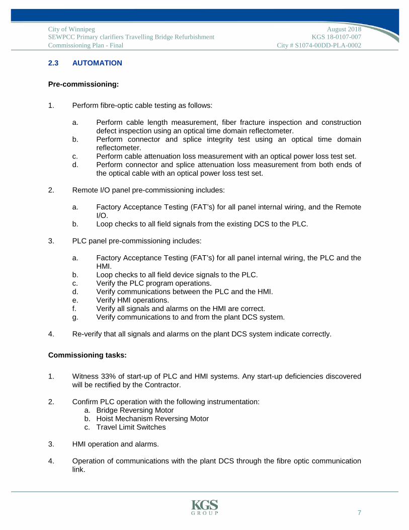
2.3 AUTOMATION Pre-commissioning: 1. Perform fibre-optic cable testing as follows:
a. Perform cable length measurement, fiber fracture inspection and construction
defect inspection using an optical time domain reflectometer. b. Perform connector and splice integrity test using an optical time domain
reflectometer. c. Perform cable attenuation loss measurement with an optical power loss test set. d. Perform connector and splice attenuation loss measurement from both ends of
the optical cable with an optical power loss test set.
2. Remote I/O panel pre-commissioning includes: a. Factory Acceptance Testing (FAT’s) for all panel internal wiring, and the Remote
I/O. b. Loop checks to all field signals from the existing DCS to the PLC.
3. PLC panel pre-commissioning includes: a. Factory Acceptance Testing (FAT’s) for all panel internal wiring, the PLC and the
HMI. b. Loop checks to all field device signals to the PLC. c. Verify the PLC program operations. d. Verify communications between the PLC and the HMI. e. Verify HMI operations. f. Verify all signals and alarms on the HMI are correct. g. Verify communications to and from the plant DCS system.
4. Re-verify that all signals and alarms on the plant DCS system indicate correctly.
Commissioning tasks: 1. Witness 33% of start-up of PLC and HMI systems. Any start-up deficiencies discovered
will be rectified by the Contractor.
2. Confirm PLC operation with the following instrumentation: a. Bridge Reversing Motor b. Hoist Mechanism Reversing Motor c. Travel Limit Switches
3. HMI operation and alarms. 4. Operation of communications with the plant DCS through the fibre optic communication
link.

City of Winnipeg August 2018 SEWPCC Primary clarifiers Travelling Bridge Refurbishment KGS 18-0107-007 Commissioning Plan - Final City # S1074-00DD-PLA-0002
8
5. Operation of the entire automation system under various conditions. 6. Check plant DCS system operation and alarms to ensure all indications and alarms
appear and are displayed correctly.
Performance verification: 1. City of Winnipeg to monitor the Primary Clarifier Travelling Bridges including all alarms.
4. Complete form CD-PM-TO-16 Certificate of Equipment Satisfactory Performance Form
103 located in specification 010001 – City Supplied Equipment and labelled “Electrical”.
2. Complete form CD-PM-TO-17 Certificate of Satisfactory Process Performance Form 104 located in specification 010001 – City Supplied Equipment and labelled “Electrical”.
Refer to Appendix B.1 for relevant City of Winnipeg Electrical and Instrumentation Checklists to
be employed during commissioning. Any forms not provided that are necessary to show
completion of the tasks described shall be developed by the contractor in an organized fashion,
in a computer generated format.

City of Winnipeg August 2018 SEWPCC Primary clarifiers Travelling Bridge Refurbishment KGS 18-0107-007 Commissioning Plan - Final City # S1074-00DD-PLA-0002
9
3.0 PROJECT TRAINING PLAN The objectives of the training are to provide City personnel with the following information:
1. How to operate the new control systems safely, and reliably. 2. Proper preventative maintenance practices along with diagnosis and trouble-shooting
information.
For the training sessions, KGS will provide a description of the new systems with instruction on
the design philosophy, criteria and intent. KGS is responsible for the coordination, quality
assurance, overall packaging and presentation of two one (1) hour classroom sessions to
provide training to two groups of City personnel.
KGS foresees providing the training for the following activities:
• KGS personnel to provide training on the operation and maintenance for the bridge electrical and automation systems complete with a demonstration.
The Contractor and any required certified factory-trained manufacturers’ personnel will provide
specific instruction on the start-up, operation and shut-down of their equipment with emphasis
on the components, control features, servicing and maintenance. Specifically, training for the
operation and maintenance of the Automation System including the PLC and the HMI is
required. The Contractor shall provide instruction on the operation of the PLC and HMI system.
The City of Winnipeg is responsible for providing appropriate personnel to participate in the
training for the operation and maintenance of the facility.
3.1 SESSION CONTENT Although KGS Group is responsible for the overall training package, the individual equipment
instructors will be responsible for the content and quality of their respective sections. In general,
the training session content is to include:
1. A review of the system.
2. The functional requirements of the system.

City of Winnipeg August 2018 SEWPCC Primary clarifiers Travelling Bridge Refurbishment KGS 18-0107-007 Commissioning Plan - Final City # S1074-00DD-PLA-0002
10
3. A review of the system layout, the equipment, controls and emergency shut off.
4. Equipment and system start-up, operation, monitoring, servicing (including trouble-shooting diagnosis), maintenance and shut-down procedures.
5. System operating sequences, including step-by-step directions for starting, operating and shutting down applicable switches and control settings.
6. A review of the O&M Manual documentation.
All training materials are to be in an acceptable digital format to the City that permits future
training procedures that provide the same degree of detail. Final review and approval of all
training manuals and materials is required by the City of Winnipeg prior to the training sessions.
Training materials in general will include the following:
1. “As-Built” contract documents.
2. Operating Manuals.
3. Maintenance Manuals.
4. Shop Drawings.
5. Product Information (PI) sheets.
6. Supplemental training materials like presentations, training videos and/or equipment
models.
7. Video recording of training sessions.

City of Winnipeg August 2018 SEWPCC Primary clarifiers Travelling Bridge Refurbishment KGS 18-0107-007 Commissioning Plan - Final City # S1074-00DD-PLA-0002
11
4.0 STATEMENT OF LIMITATIONS AND CONDITIONS 4.1 THIRD PARTY USE OF REPORT This report has been prepared for the City of Winnipeg (City) and their Contractors and/or
potential bidders for the SEWPCC Primary Clarifiers Travelling Bridges Refurbishment project to
whom this report has been addressed and use by any other party of this report, or any reliance
on or decisions made based on it, are the responsibility of such third parties. KGS Group
accepts no responsibility for damages, if any, suffered by any third party as a result of decisions
made or actions undertaken based on this report.

City of Winnipeg August 2018 SEWPCC Primary clarifiers Travelling Bridge Refurbishment KGS 18-0107-007 Commissioning Plan - Final City # S1074-00DD-PLA-0002
APPENDIX A
TRIMMED PROJECT SCHEDULE

ID Task Name Duration Start Finish
43
Delivery of Contractor Supplied
PLC's/Control Panels, etc
35 daysThu
15/11/18
Fri
11/01/19
44
Clarifier 3 - City Shuts down and
prepares clarifier
3 days Wed
28/11/18
Mon
03/12/18
45
Clarifier 3 - Refurbish 48 daysMon
03/12/18
Fri
15/02/19
46
Clarifier 3 - Pre-commissioning
Meeting
0 days Mon
04/02/19
Mon
04/02/19
47
Clarifier 3 - Pre-commissioning Tasks10 daysMon
04/02/19
Fri
15/02/19
48
Clarifier 3 - Commissioning -
Dry/Wet
20 daysMon
18/02/19
Fri
15/03/19
49
Clarifier 3 - Training 5 days Mon
18/02/19
Fri
22/02/19
50
Clarifier 3 - Performance Verification15 daysMon
25/02/19
Fri
15/03/19
51
Clarifier 2 - City shuts down and
prepares clarifier
2 days Tue
29/10/19
Wed
30/10/19
52
Clarifier 2 - Refurbish 15 daysThu
31/10/19
Wed
20/11/19
53
Clarifier 2 - Precommissioning
Meeting
0 days Wed
20/11/19
Wed
20/11/19
54
Clarifier 2 - Pre-commissioning Tasks0 days Wed
20/11/19
Wed
20/11/19
55
Clarifier 2 - Commissioning Dry/Wet 5 days Thu
21/11/19
Wed
27/11/19
56
Clarifier 2 - Training 2 days Thu
21/11/19
Fri
22/11/19
58
Clarifier 2 - Performance Verification3 days Mon
25/11/19
Wed
27/11/19
59
Clarifier 1 - City shuts down and
prepares clarifier
2 days Thu
28/11/19
Fri
29/11/19
60
Clarifier 1 - Refurbish 10 daysMon
02/12/19
Fri
13/12/19
61
Clarifier 1 - Precommissioning
Meeting
0 days Fri
13/12/19
Fri
13/12/19
62
Clarifier 1 - Commissioning dry/wet
& Training
4 days Mon
16/12/19
Thu
19/12/19
63
Substantial Performance Inspection
and Report
0 days Thu
19/12/19
Thu
19/12/19
04/02
20/11
20/11
13/12
19/12
November December January February March April May June July August September October November December
SEWPCC - PRIMARY CLARIFIER 1-3 UPGRADE PROJECT - COMMISSIONING
KGS Project 18-0107-007
City of Winnipeg Bid Opportunity 463-2017Page 1 of 1

City of Winnipeg August 2018 SEWPCC Primary clarifiers Travelling Bridge Refurbishment KGS 18-0107-007 Commissioning Plan - Final City # S1074-00DD-PLA-0002
APPENDIX B.1
CITY OF WINNIPEG ELECTRICAL AND INSTRUMENTATION COMMISSIONING CHECKLISTS

INSPECTION FORM
AUTOMATION – CONTROL CONDUCTORS Page 1 of 1
ID:
Proj
ect Facility: Project Name:
Area : Bid Opportunity:
Cab
le/C
ondu
it D
ata
Source: Dest.:
Installation: Cable
Cable Tray Strapped
Direct Buried
Conduit EMT Rigid Steel
Alum. PVC
Other:
No. of Conductors: Size: AWG Type: Rated Voltage: V
Visu
al
Insp
ectio
n Cable Identification Tag Installed: Yes No N/A Enclosure Entry Acceptable: Yes No
Wire tags installed: Yes No Conduit / Cable Supported Appropriately: Yes No
Comments:
Insu
latio
n R
esis
tanc
e Te
st
Test Voltage: V Ambient Temperature: °C All conductors not under test grounded for each
reading: Yes No
# ID MΩ # ID MΩ # ID MΩ
1 19 37
2 20 38
3 21 39
4 22 40
5 23 41
6 24 42
7 25 43
8 26 44
9 27 45
10 28 46
11 29 47
12 30 48
13 31 49
14 32 50
15 33 51
16 34 52
17 35 53
18 36 54
1. Utilize 1000VDC Test Voltage for 600V rated cables, 500VDC for cables rated <= 300V. 2. Utilize a single form for each cable / conduit. 3. Disconnect both ends of wiring prior to tests. 4. Test each conductor to ground. All conductors not under test must be grounded during each test. 5. Each reading must not be less than 22 MΩ or significantly less than comparable conductors.
Comments:
Test Summary: Test Passed Test Failed
Company Name Signature Date (yyyy/mm/dd)
Performed By
Checked By

INSPECTION FORM
AUTOMATION – TWISTED SHIELDED PAIRS Page 1 of 2
Cable ID:
Proj
ect Facility: Project Name:
Area : Bid Opportunity:
Cab
le/C
ondu
it D
ata
Source: Dest.:
Installation: Cable
Cable Tray Strapped
Direct Buried
Conduit EMT Rigid Steel
Alum. PVC
Other:
No. of Pairs: Size: AWG Type: Rated Voltage: V
Visu
al
Insp
ectio
n Cable Identification Tag Installed: Yes No N/A Enclosure Entry Acceptable: Yes No
Wire tags installed: Yes No Conduit / Cable Supported Appropriately: Yes No
Comments:
Insu
latio
n R
esis
tanc
e Te
st
Test Voltage: V Ambient Temperature: °C All conductors not under test grounded for each
reading: Yes No
Pr ID Cond. 1 (+)
to Gnd (MΩ)
Cond. 2 (-) to Gnd (MΩ)
Shield to Gnd (MΩ)
Pr ID Cond. 1 (+)
to Gnd (MΩ)
Cond. 2 (-) to Gnd (MΩ)
Shield to Gnd (MΩ)
1 13
2 14
3 15
4 16
5 17
6 18
7 19
8 20
9 21
10 22
11 23
12 24
1. Utilize 1000VDC Test Voltage for 600V rated cables, 500VDC for cables rated <= 300V. 2. Utilize a single form for each cable / conduit. 3. Disconnect both ends of wiring prior to tests. 4. Test each conductor to ground. All conductors and shields not under test must be grounded during each test. 5. Each reading must not be less than 22 MΩ or significantly less than comparable conductors.
Comments:
Test Summary: Test Passed Test Failed
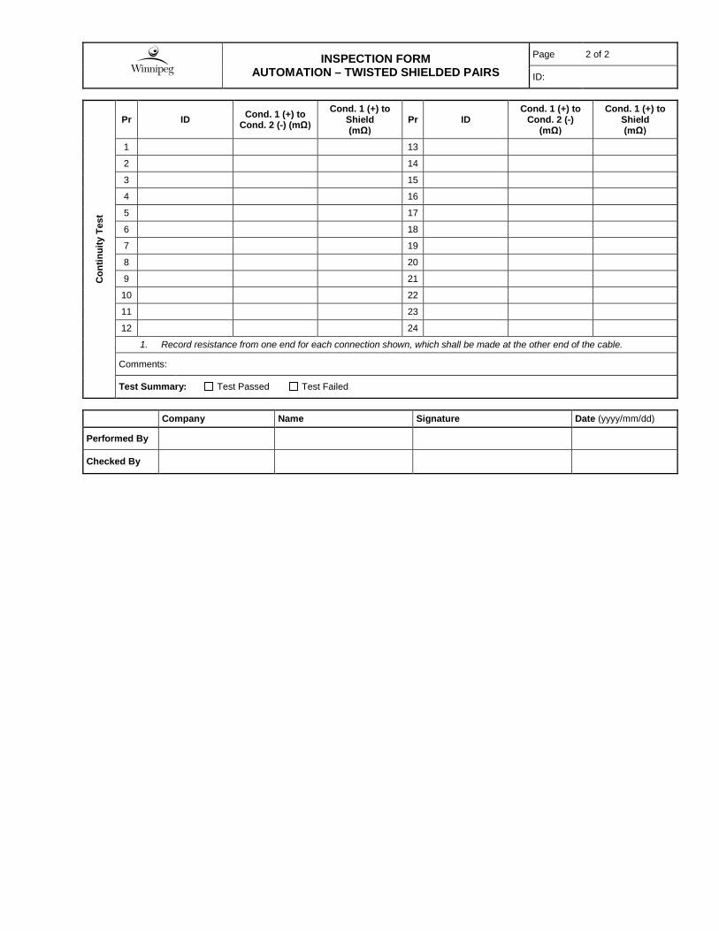
INSPECTION FORM
AUTOMATION – TWISTED SHIELDED PAIRS Page 2 of 2
ID:
Con
tinui
ty T
est
Pr ID Cond. 1 (+) to Cond. 2 (-) (mΩ)
Cond. 1 (+) to Shield (mΩ)
Pr ID Cond. 1 (+) to
Cond. 2 (-) (mΩ)
Cond. 1 (+) to Shield (mΩ)
1 13
2 14
3 15
4 16
5 17
6 18
7 19
8 20
9 21
10 22
11 23
12 24
1. Record resistance from one end for each connection shown, which shall be made at the other end of the cable.
Comments:
Test Summary: Test Passed Test Failed
Company Name Signature Date (yyyy/mm/dd)
Performed By
Checked By

INSPECTION FORM
POWER CABLE < 1000V Page 1 of 1
Cable ID:
Proj
ect Facility: Project Name:
Area : Bid Opportunity:
Cab
le D
ata
Source: Dest. / Load:
Manufacturer: Type: Conductor: Copper Aluminum
No. of Conductors: Size: AWG
MCM Length: m Measured Jacket Markings
Previous Data TDR
Rated Voltage: V Operating Voltage: V Date Installed:
Installation: Cable Tray Strapped
EMT Steel Conduit
Alum. Conduit PVC Conduit
Direct Buried Underground Duct Other:
Visu
al
Insp
ectio
n Physical Damage on Exposed Ends: Yes No Cable Identification Tag Installed: Yes No
Visual Signs of Overheating: Yes No Cable Supported Appropriately: Yes No
Bend Radius Acceptable: Yes No Comments:
Insu
latio
n R
esis
tanc
e Te
st
Test Preparation:
Source: Disconnected Connected with Source Isolated
Cable Dest. / Load: Disconnected Connected with Load Isolated
Note: Approval of City’s Representative is required, prior to leaving cables connected during the test.
Cable Temperature: °C Temperature Correction Factor for 20°C: Ground all conductors not under test for each reading.
Test Voltage
Insulation Resistance (MΩ) Test Summary
Test Passed Test Inconclusive
Further Investigation Required. Test Failed
A-GND B-GND C-GND N-GND
V Reading
Corrected to 20oC
Utilize 1000VDC Test Voltage for 600V rated cables, 500VDC for cables rated <= 300V.
Comments:
Con
nect
ion
Res
ista
nce Note: Torque check required for all cables. Connection Resistance Test required for cables 4/0 AWG or larger.
Termination Connection Resistance (μΩ) - As Left
Torque Check A B C N
Source OK
Dest. / Load OK
Comments:
Fina
l A
naly
sis Cable Returned to Service: Yes No Comments:
Monitoring / Further Inspection Required: Yes No
Repair / Replacement Required: Yes No
Company Name Signature Date (yyyy/mm/dd)
Performed By
Checked By

INSPECTION FORM
GROUNDING/BONDING CONNECTION RESISTANCE Page 1 of 2
Area:
Proj
ect Facility: Project Name:
Area : Bid Opportunity:
Res
ista
nce
Che
cks
(D
ucto
r Tes
t)
Point A Point B Resistance (mΩ) Acceptable
Yes No Inconclusive
Yes No Inconclusive
Yes No Inconclusive
Yes No Inconclusive
Yes No Inconclusive
Yes No Inconclusive
Yes No Inconclusive
Yes No Inconclusive
Yes No Inconclusive
Yes No Inconclusive
Yes No Inconclusive
Yes No Inconclusive
Yes No Inconclusive
Yes No Inconclusive
Yes No Inconclusive
Yes No Inconclusive
Yes No Inconclusive
Yes No Inconclusive
Yes No Inconclusive
Yes No Inconclusive
Yes No Inconclusive
Yes No Inconclusive
Yes No Inconclusive
Yes No Inconclusive
Yes No Inconclusive
Comments:

INSPECTION FORM
GROUNDING/BONDING CONNECTION RESISTANCE Page 2 of 2
ID:
Res
ista
nce
Che
cks
(D
ucto
r Tes
t)
Point A Point B Resistance (mΩ) Acceptable
Yes No Inconclusive
Yes No Inconclusive
Yes No Inconclusive
Yes No Inconclusive
Yes No Inconclusive
Yes No Inconclusive
Yes No Inconclusive
Yes No Inconclusive
Yes No Inconclusive
Yes No Inconclusive
Yes No Inconclusive
Yes No Inconclusive
Yes No Inconclusive
Comments:
Fina
l A
naly
sis Monitoring / Inspection Required: Yes No Comments:
Repair / Replacement Required: Yes No
Company Name Signature Date (yyyy/mm/dd)
Performed By
Checked By
Note: The person performing the check is responsible for ensuring that the data is transcribed from the handwritten form correctly, and that
the analysis results are correct.
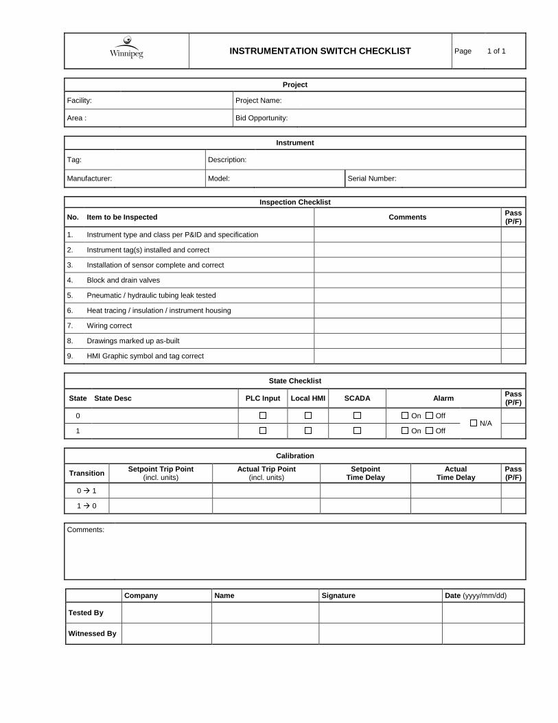
INSTRUMENTATION SWITCH CHECKLIST Page 1 of 1
Project
Facility: Project Name:
Area : Bid Opportunity:
Instrument
Tag: Description:
Manufacturer: Model: Serial Number:
Inspection Checklist
No. Item to be Inspected Comments Pass (P/F)
1. Instrument type and class per P&ID and specification
2. Instrument tag(s) installed and correct
3. Installation of sensor complete and correct
4. Block and drain valves
5. Pneumatic / hydraulic tubing leak tested
6. Heat tracing / insulation / instrument housing
7. Wiring correct
8. Drawings marked up as-built
9. HMI Graphic symbol and tag correct
State Checklist
State State Desc PLC Input Local HMI SCADA Alarm Pass (P/F)
0 On Off N/A
1 On Off
Calibration
Transition Setpoint Trip Point (incl. units)
Actual Trip Point (incl. units)
Setpoint Time Delay
Actual Time Delay
Pass (P/F)
0 1
1 0
Comments:
Company Name Signature Date (yyyy/mm/dd)
Tested By
Witnessed By
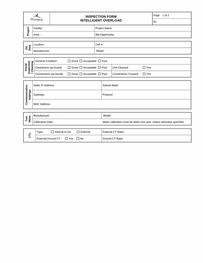
INSPECTION FORM
INTELLIGENT OVERLOAD Page 1 of 2
ID:
Proj
ect Facility: Project Name:
Area : Bid Opportunity:
O/L
D
ata Location: Cell #:
Manufacturer: Model:
Visu
al
Insp
ectio
n / C
lean
ing General Condition: Good Acceptable Poor
Cleanliness (as found) Good Acceptable Poor Unit Cleaned: Yes
Connections (as found) Good Acceptable Poor Connections Torqued: Yes
Com
mun
icat
ion
Setti
ngs
Static IP Address: Subnet Mask
Gateway: Protocol:
MAC Address:
Test
M
eter
Manufacturer: Model:
Calibration Date: Meter calibration must be within one year, unless otherwise specified.
CTs
Type: Internal to O/L External External CT Ratio:
External Ground CT: Yes No Ground CT Ratio:
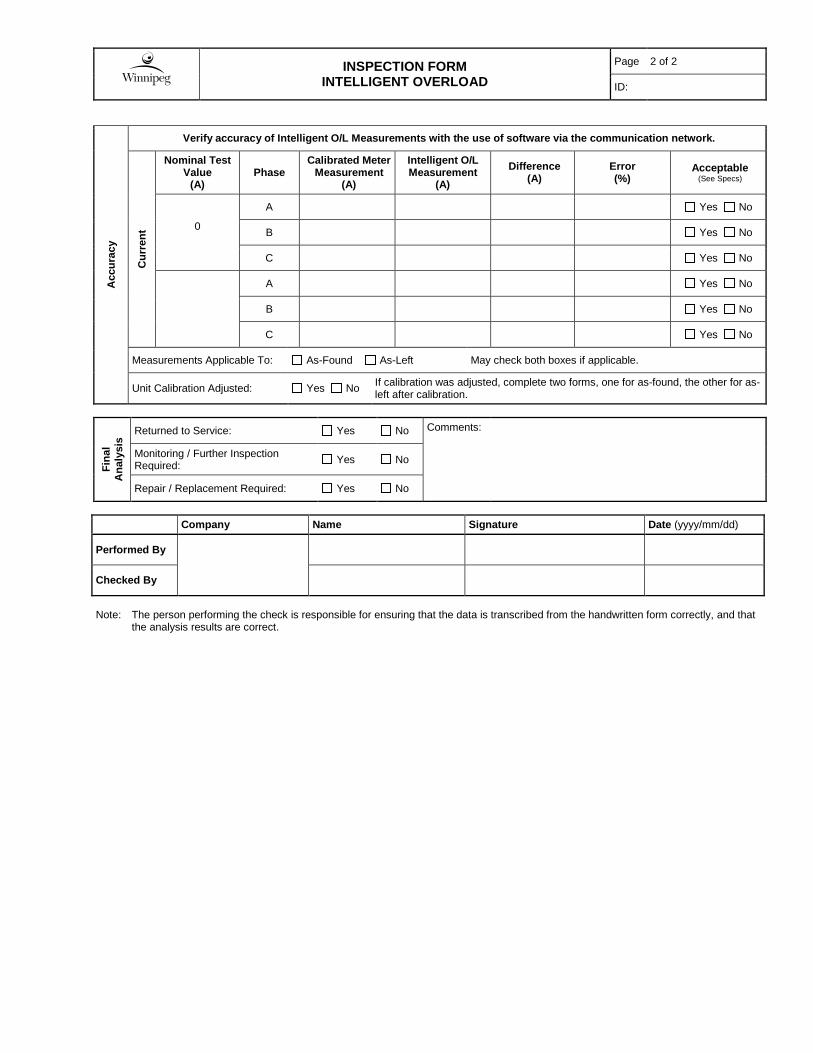
INSPECTION FORM
INTELLIGENT OVERLOAD Page 2 of 2
ID:
Acc
urac
y
Verify accuracy of Intelligent O/L Measurements with the use of software via the communication network. C
urre
nt
Nominal Test Value
(A) Phase
Calibrated Meter Measurement
(A)
Intelligent O/L Measurement
(A) Difference
(A) Error (%)
Acceptable (See Specs)
0
A Yes No
B Yes No
C Yes No
A Yes No
B Yes No
C Yes No
Measurements Applicable To: As-Found As-Left May check both boxes if applicable.
Unit Calibration Adjusted: Yes No If calibration was adjusted, complete two forms, one for as-found, the other for as-left after calibration.
Fina
l A
naly
sis
Returned to Service: Yes No Comments:
Monitoring / Further Inspection Required: Yes No
Repair / Replacement Required: Yes No
Company Name Signature Date (yyyy/mm/dd)
Performed By
Checked By
Note: The person performing the check is responsible for ensuring that the data is transcribed from the handwritten form correctly, and that
the analysis results are correct.

INSPECTION FORM
MOTOR STARTER, FVNR, BASIC Page 1 of 1
ID:
Proj
ect Facility: Project Name:
Area : Bid Opportunity:
Star
ter D
ata
Load: Starter Location: Cell #:
Manufacturer: Type: Size: Rated Voltage: V
Circuit Protection:
Fused Disc. Fuse Size: A
Breaker MCP Rating: A Inst. Setting: A
Manufacturer:
Model:
Overload Protection:
Thermal Electronic Class:
10 20 30 Unknown
Setting / Rating: A Manufacturer:
Model:
Visu
al In
spec
tion
/ Cle
anin
g
Starter Identification Tag Installed: Yes No Visual Signs of Overheating: Yes No
Cleanliness (As Found): Good Acceptable Poor Electro/Mechanical Interlock: Good Acceptable Poor
Connections Good Acceptable Poor Contactor Condition: Good Acceptable Poor
Ground Connection: Good Acceptable Poor Overload Condition: Good Acceptable Poor
Cables Routed Appropriately: Yes No Door Mechanical Good Acceptable Poor
Exercise Circuit Breaker/MCP/Disconnect Yes Unit Cleaned: Yes
Comments:
Fina
l A
naly
sis
Returned to Service: Yes No Comments:
Monitoring / Further Inspection Required: Yes No
Repair / Replacement Required: Yes No
Company Name Signature Date (yyyy/mm/dd)
Performed By
Checked By
Note: The person performing the check is responsible for ensuring that the data is transcribed from the handwritten form correctly, and that
the analysis results are correct.

INSPECTION FORM
AC MOTOR, LOW VOLTAGE Page: 1 of 2
ID:
Pr
ojec
t Facility: Project Name:
Area : Bid Opportunity:
Mot
or D
ata
Size: kW / HP Voltage: V R.P.M:
Manufacturer: Model: Serial Number:
Frame Type: FLA: A Service Factor: Other:
Cooling: Air Fan # Cooling Fans: Winding
Material:
Visu
al In
spec
tion
/ Cle
anin
g
Motor Identification Tag Installed: Yes No Visual Signs of Overheating: Yes No
Connections: Good Acceptable Poor Air Baffles: Good Acceptable Poor
Paint: Good Acceptable Poor Filter Media: N/A Good Acceptable Poor
Cooling Fans: N/A Good Acceptable Poor Fan Controls: N/A Good Acceptable Poor
Anchorage/Alignment: Good Acceptable Poor
Ground Connection: Good Acceptable Poor
Mechanical/Electrical Noise During Operation: Yes No Lubrication Required: Yes No
Cleanliness (As Found): Good Acceptable Poor Unit Cleaned: Yes Photograph Taken: Yes
Win
ding
Insu
latio
n R
esis
tanc
e
Stator Winding Test
Voltage (Vdc)
Winding Temperature (°C)
Resistance (MΩ) Dielectric Absorption
Ratio Polarization
Index (a) 30 Sec 1 min. 10 min. (a)
500 - -
40
500 - -
40
500 - -
40
Notes:
(a) Testing to 10 minutes and calculation of Polarization Index is only required for motors > 150 kW (200 HP)
Test Summary Test Passed Test Inconclusive. Further Investigation Required. Test Failed
Win
ding
R
esis
tanc
e
Resistance (μΩ) Test Summary
A - B B – C A - C Test Passed Test Inconclusive
Further Investigation Required. Test Failed
Comments:

INSPECTION FORM
AC MOTOR, LOW VOLTAGE Page: 2 of 2
ID:
B
earin
g In
sula
tion
Res
ista
nce
Not Applicable
Bearing Test Voltage (Vdc)
Bearing Temperature (°C)
Resistance (MΩ)
1 min. Corrected to 40°C
500
500
Test Summary Test Passed Test Inconclusive. Further Investigation Required. Test Failed
RTD
Res
ista
nce
Not Applicable
Actual Winding Temperature: °C Actual Bearing Temperature °C
RTD Resistance (Ω)
Calculated Temperature
(°C) RTD Resistance
(Ω) Calculated
Temperature (°C)
Test Summary Test Passed Test Inconclusive. Further Investigation Required. Test Failed Note: Test connection resistance of bolted connections. Report on cable inspection sheet.
Fina
l A
naly
sis
Returned to Service: Yes No Comments:
Monitoring / Further Inspection Required: Yes No
Repair / Replacement Required: Yes No
Company Name Signature Date (yyyy/mm/dd)
Performed By
Checked By
Note: The person(s) performing the check is responsible for ensuring that the data is transcribed from the handwritten form correctly, and that the analysis results are correct.

PLC DISCRETE INPUT CHECKLIST Page 1 of 2
Project
Facility: Project Name:
Area : Bid Opportunity:
PLC
PLC ID: Description:
Rack: Slot:
Pt Tag Description State State Desc. PLC Input
Local HMI SCADA Alarm Pass
(P/F)
0 On Off
N/A 1 On Off
0 On Off
N/A 1 On Off
0 On Off
N/A 1 On Off
0 On Off
N/A 1 On Off
0 On Off
N/A 1 On Off
0 On Off
N/A 1 On Off
0 On Off
N/A 1 On Off
0 On Off
N/A 1 On Off
0 On Off
N/A 1 On Off
0 On Off
N/A 1 On Off
0 On Off
N/A 1 On Off
0 On Off
N/A 1 On Off
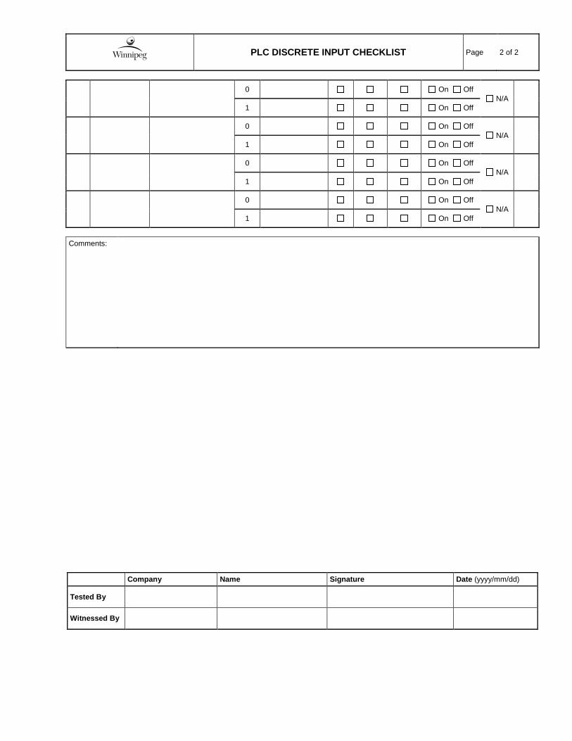
PLC DISCRETE INPUT CHECKLIST Page 2 of 2
0 On Off
N/A 1 On Off
0 On Off
N/A 1 On Off
0 On Off
N/A 1 On Off
0 On Off
N/A 1 On Off
Comments:
Company Name Signature Date (yyyy/mm/dd)
Tested By
Witnessed By

PLC DISCRETE OUTPUT CHECKLIST Page 1 of 2
Project
Facility: Project Name:
Area : Bid Opportunity:
PLC
PLC ID: Description:
Rack: Slot:
Pt Tag Description State State Desc. PLC Output Field Device Pass (P/F)
0
1
0
1
0
1
0
1
0
1
0
1
0
1
0
1
0
1
0
1
0
1
0
1

PLC DISCRETE OUTPUT CHECKLIST Page 2 of 2
0
1
0
1
0
1
0
1
Comments:
Company Name Signature Date (yyyy/mm/dd)
Tested By
Witnessed By

City of Winnipeg August 2018 SEWPCC Primary clarifiers Travelling Bridge Refurbishment KGS 18-0107-007 Commissioning Plan - Final City # S1074-00DD-PLA-0002
APPENDIX B.2
CITY OF WINNIPEG MECHANICAL COMMISSIONING CHECKLIST

COMMISSIONING MECHANICAL CHECKLIST Page 1 of 1
Project
Facility: SEWPCC Project Name: SEWPCC PRIMARY CLARIFIER TRAVELLING BRIDGES - REFURBISHMENT
Area : Primary Clarifier No.3 City Bid Op. # 682-2018
Equipment List
Tag: N/A Description: Travelling Bridge Collector
Manufacturer: Dorr-Oliver Canada Model: N/A Serial Number: 11798-1
Inspection Checklist
No. Item to be Inspected Comments Pass (P/F)
1.
Test run the bridge collector along the full length of the rails without the scraper arm assembly attached and with the clarifier empty. See drawing L-32917 for design speed. See Westinghouse bridge drive motor datasheet for operating current.
Company Name Signature Date (yyyy/mm/dd)
Tested By
Witnessed By
No. Item to be Inspected Comments Pass (P/F)
2. Test run the bridge collector with the scraper arm assembly attached and with the clarifier empty. Confirm the same minimum performance requirements stated in item 1.
Company Name Signature Date (yyyy/mm/dd)
Tested By
Witnessed By
No. Item to be Inspected Comments Pass (P/F)
3. Test run the bridge collector with the scraper arm assembly attached and with the clarifier full. Confirm the same minimum performance requirements stated in item 1.
Company Name Signature Date (yyyy/mm/dd)
Tested By
Witnessed By
Comments:
