appendix c lowering of material into trench ..... 26 4.11 installation of pipe..... 27 4.12...
TRANSCRIPT

RULES AND REGULATIONS FOR
WATER AND WASTEWATER SERVICE
APPENDIX C
STANDARD SPECIFICATIONS FOR WATER MAINS
Last Approved Revision: March 9, 2018

Page | ii
TABLE OF CONTENTS
SECTION I – GENERAL ................................................................................................................5
1.1 Authority ........................................................................................................................................... 5
1.2 Effective Date of Specifications ....................................................................................................... 5
1.3 Revisions, Amendments, or Additions ............................................................................................. 5
1.4 Definitions ........................................................................................................................................ 5
1.5 Development Approval and Infrastructure Acceptance ................................................................... 5
1.6 Variance ........................................................................................................................................... 5
SECTION II – DISTRIBUTION SYSTEM DESIGN AND LAYOUT .................................................7
2.1 General Requirements ..................................................................................................................... 7
2.2 Corrosion ......................................................................................................................................... 7
2.3 Sizing Distribution Mains ................................................................................................................. 7
2.4 Fire Protection .................................................................................................................................. 7
2.5 Distribution Regulating Requirements ............................................................................................. 8
2.6 Layout of the Distribution System .................................................................................................... 8
2.7 Operating Pressures ...................................................................................................................... 11
2.8 Protection of Potable Water Supplies ............................................................................................ 11
SECTION III – MATERIAL SPECIFICATIONS ............................................................................ 12
3.1 General Requirements ................................................................................................................... 12
3.2 Pipe and Fittings ............................................................................................................................ 12
3.3 Valves ............................................................................................................................................ 15
3.4 Fire Hydrants ................................................................................................................................. 17
3.5 Marking Tape ................................................................................................................................. 18
3.6 Thrust Blocks and Anchors ............................................................................................................ 18
3.7 Precast Concrete Manholes and Vaults ........................................................................................ 19
3.8 Casing Materials and Spacers ....................................................................................................... 21
3.9 Tracer Wire and Joint Bonding ...................................................................................................... 22
3.10 Automated Flushing Stations ......................................................................................................... 22
SECTION IV – PIPE INSTALLATION AND INSPECTION........................................................... 24
4.1 Safety ............................................................................................................................................. 24
4.2 Handling of Materials ..................................................................................................................... 24
4.3 Inspection ....................................................................................................................................... 24
4.4 Inspection and Preparation of Pipe and Fittings ............................................................................ 25
4.5 Cutting and Fitting of Pipe ............................................................................................................. 25
4.6 Pipe Joints ..................................................................................................................................... 26
4.7 Pipe Alignment and Grade ............................................................................................................. 26
4.8 Temporary Plugs............................................................................................................................ 26
4.9 Frost ............................................................................................................................................... 26
4.10 Lowering of Material into Trench ................................................................................................... 26
4.11 Installation of Pipe.......................................................................................................................... 27
4.12 Installation of Valves ...................................................................................................................... 29
4.13 Fire Hydrants ................................................................................................................................. 29
4.14 Thrust Blocks and Anchors ............................................................................................................ 31
4.15 Air Vac Vaults ................................................................................................................................ 32
4.16 Tie in to the District System ........................................................................................................... 32
SECTION V – Testing and Acceptance ..................................................................................... 35
5.1 General Requirements ................................................................................................................... 35
5.2 Disinfection .................................................................................................................................... 35

Page | iii
5.3 Hydrostatic Pressure Testing ......................................................................................................... 37
5.4 Acceptance and Release for Taps ................................................................................................. 38
SECTION VI – STANDARD FORMS and Details ....................................................................... 39
Form 6.1: Pre-Construction Checklist for Water Mainline Installations ..................................................... 40
FORM 6.2: WATER SYSTEM ACCEPTANCE PROCEDURE ................................................................................. 43
FORM 6.3: BILL OF SALE – WATER MAIN ....................................................................................................... 44
FORM 6.4: WATER EASEMENT – EAGLE RIVER WATER & SANITATION DISTRICT ............................................. 46
FORM 6.5: WATER EASEMENT – UPPER EAGLE REGIONAL WATER AUTHORITY ............................................... 48
FORM 6.6: LENDER’S CONSENT .................................................................................................................... 50
C-01: COMBINATION AIR VALVE/VACUUM VALVE + MANHOLE ........................................................................ 51
C-02: COMBINATION AIR VALVE/VACUUM VALVE + MANHOLE (HIGH GROUNDWATER) ..................................... 52
C-03: CONCRETE THRUST BLOCKS .............................................................................................................. 53
C-04: PARALLEL BENDS ............................................................................................................................... 54
C-05: VERTICAL THRUST BLOCK................................................................................................................... 55
C-06: TEE DETAIL ........................................................................................................................................ 56
C-07: 90° CROSS DETAIL ............................................................................................................................. 57
C-08: FIRE HYDRANT ASSEMBLY .................................................................................................................. 58
C-09: GATE VALVE AND BOX ASSEMBLY ....................................................................................................... 59
C-10 ANCHOR BLOCK CUTOFF COLLAR ........................................................................................................ 60
C-11: GROUNDWATER BARRIER ................................................................................................................... 61
C-12: WATERLINE CASING DETAIL ................................................................................................................ 62
C-13: POLYETHYLENE WRAP ........................................................................................................................ 63
C-14: MINIMUM COVER AND CULVERT CROSSING INSULATION DETAIL ............................................................ 64
C-15: EASEMENT WIDTH DETAIL .................................................................................................................. 65

Page | 4

Page | 5
SECTION I – GENERAL
1.1 Authority
The Standard Specifications for Water Mains as set forth herein (“Specifications”) are
promulgated by the following: Arrowhead Metropolitan District, Bachelor Gulch
Metropolitan District, Beaver Creek Metropolitan District, Berry Creek Metropolitan
District, Cordillera Metropolitan District, Eagle River Water & Sanitation District, EagleVail
Metropolitan District, Edwards Metropolitan District, Town of Avon, Traer Creek
Metropolitan District (Village at Avon), and Upper Eagle Regional Water Authority
(“District”). The interpretation and enforcement of said Specifications is hereby delegated
to the Regulations Administrator of the Eagle River Water & Sanitation District.
1.2 Effective Date of Specifications
The Specifications shall become effective immediately upon formal adoption by the
District and shall supersede all former specifications for water main construction. The
most current version of these Specifications is available at www.erwsd.org.
1.3 Revisions, Amendments, or Additions
The Specifications may be revised and/or amended. Such revisions, amendments, and
additions shall be binding and in full force immediately upon formal adoption by the
District.
1.4 Definitions
Please reference the Rules and Regulations for Water and Wastewater Service, Article II.
1.5 Development Approval and Infrastructure Acceptance
Please reference the Rules and Regulations for Water and Wastewater Service, Articles
VIII and IX, respectively.
1.6 Variance
The District recognizes that the strict and literal interpretation of these Rules and
Regulations may not be possible in all cases. Please refer to Article VII for information on
the Variance process.

Page | 6

Page | 7
SECTION II – DISTRIBUTION SYSTEM DESIGN AND LAYOUT
2.1 General Requirements
The District requires an Overall Utility Site Plan of the project to be submitted indicating all
utilities and their proposed locations for review prior to Construction Plan Approval. All
plans submitted shall include a geotechnical report if requested by the District. The
design and installation of all facilities shall ensure development of an integrated
distribution system.
2.2 Corrosion
Corrosive soils are present in the District’s service area and may lead to the premature
degradation of pipe materials and appurtenances. Please refer to Article IX for corrosive
soils procedure.
2.2.1 Dissimilar Materials Cathodic protection and insulation shall be installed as required by the District.
Particular care shall be taken to insulate between dissimilar materials.
2.2.2 Insulating Joints Whenever it is necessary to join pipe of dissimilar metal, or when designated by
the District, a method of insulating against the passage of electrical current,
approved by the District, shall be provided. Special care shall be exercised during
the installation of these joints to prevent electrical conductivity across the joints.
2.3 Sizing Distribution Mains
All mains shall be sized large enough to provide for domestic, irrigation, and fire
protection flows to the area requesting service without exceeding maximum pipe
velocities of 8 feet per second. The minimum size of all District mains shall be
eight inches (8").
The District reserves the right to request oversized mains to provide service for projected
future needs. The additional cost for the oversizing may be negotiated between the
District and the Applicant and will be reviewed on a case-by-case basis.
2.4 Fire Protection
The Applicant shall coordinate with the District and local fire protection jurisdiction to
determine minimum fire protection flow and shall design line sizes accordingly. The
quantity and location of fire hydrants in a given area must be approved by the appropriate
governmental agency.

SECTION II – DISTRIBUTION SYSTEM DESIGN AND LAYOUT
Page | 8
The Applicant shall perform all fire hydrant “flow tests”. Results of “flow tests” shall be
provided to the District and to the local fire authority. All costs associated with the “flow
test” shall be borne by the Applicant. The District shall witness and oversee the “flow
test” in conjunction with other appropriate governmental agencies.
2.5 Distribution Regulating Requirements
Regulating installations are required to control pressure, provide pressure relief, and
separate pump and gravity zones throughout the distribution system. When main
extension plans are submitted for review, the need for regulating installations must be
approved by the District as determined by existing and proposed pressure zones, booster
pump areas and the existing distribution system piping. Regulating installations shall be
categorized as follows:
(a) Pressure Regulating Station
(b) Check Valve Station
(c) Surge Control Station
Location, design, and pressure settings of main line pressure regulating devices will be
determined by the District on a case-by-case basis. All regulating installations are
considered Major Facilities and will be designed and constructed by the District.
2.6 Layout of the Distribution System
2.6.1 Easement Width Requirements for Main Installations All mains shall be installed in dedicated public street right-of-ways or dedicated
water line easements. The standard easement width for all mains shall be a
minimum of 20 feet and depth of cover shall be 7 feet to 9.5 feet. The main shall be
generally centered within the easement. The easement width shall be in
accordance with Standard Detail C-15.
2.6.2 Fire Hydrants Fire hydrant branch lines shall be set at right angles to street mains. The fire
hydrant shall be set at the end of the branch line and shall face the direction as
dictated per local fire authority. No horizontal bends or offsets shall be used in
installing fire hydrant branch lines unless approved by the District. Under no
circumstances shall any size or manner of tap be made on a fire hydrant branch
line between the hydrant and hydrant valve. The maximum length of a 6-inch
hydrant branch line is 50 feet. All fire hydrant valves shall be attached to the tee
off of the main. A fire hydrant shall be installed at the end of all dead end water
mains.

SECTION II – DISTRIBUTION SYSTEM DESIGN AND LAYOUT
Page | 9
Fire hydrant depths shall be 7-feet to 9.5-feet. All fire hydrants shall be installed
within dedicated streets, right-of-ways, or easements as herein above defined.
Fire hydrant flange elevations shall be indicated on plans.
Fire hydrants shall be installed at locations approved by the Fire Department, the
District and the appropriate governmental agency.
2.6.3 Line Valves Line valves are required at a minimum of every one thousand (1,000) feet.
Additional valves, subject to District approval, are required to further isolate the
system at all main branches, and at other locations as determined by the District
for operation of the water system. A smaller diameter bypass line and valve may
be required to facilitate large diameter valve opening in high pressure applications,
as determined on a case-by-case basis. The applicant shall identify all locations
on their submittal where line diameters exceed 12” and static pressures exceed
100psi. The District will then determine the appropriate desired solution (valve type
and/or bypass).
2.6.4 Joint Restraint Water mains require the use of joint restraints such as thrust blocks and
mechanical joint restraints. Mechanical joint restraints shall be used in conjunction
with all thrust block installations. Thrust blocks may be eliminated at the District’s
discretion on a case-by-case basis if joint restraints and restrained pipe lengths
have been calculated by a Registered Professional Engineer. When water mains
are installed in a fill condition rather than in undisturbed earth, mechanical joint
restraints shall be required at all pipe connections.
All thrust blocks shall be constructed per the District’s Concrete Thrust Block
details C-03, C-04, and C-05 and Material Specification 3.6. Submitted
construction drawings shall identify all thrust blocks with specific station numbers
(at valves, fire hydrants, bends & where required). All thrust blocks shall be
inspected and approved by the District Inspector prior to backfill.
2.6.5 Groundwater Barriers Groundwater barriers may be required in areas where the groundwater table is
encountered. The contractor shall notify the Engineer and District Inspector
immediately if groundwater is encountered in an excavation.
2.6.6 Depth of Bury
The depth of cover for water lines shall be a minimum of seven feet (7') and a
maximum of nine feet six inches (9'-6") from finish grade to the top of the water
line. Profiles of water lines shall be submitted in accordance with Article IX.

SECTION II – DISTRIBUTION SYSTEM DESIGN AND LAYOUT
Page | 10
2.6.7 Location Tape
All lines connected to District mains in any way shall be marked with the
appropriate locating tape per Section 3.5.
2.6.8 Abandonment of Existing Water Mains and Valves
All abandoned water mains shall be appropriately terminated at the main
connection. The Contractor shall maintain the existing waterline until such time as
the new waterline has been pressure tested, chlorinated, bacteria tested and
accepted. Valve stacks on abandoned lines shall be completely removed and
backfilled.
2.6.9 Pipe Deflections/Bends
All plans must indicate deflections, elbows, bends, and the degree of deflection.
Pipe deflections shall not exceed the Manufacturer's maximum recommended
deflection or the values identified in Table C-1, below, whichever is lower. . Joint
restraints shall be used in all change of direction fittings. The use of two 45-degree
elbows is preferable to the use of 90-degree elbows. The use of 90-degree elbows
will be considered on a case-by-case basis.
Normal
Pipe Size (in.)
Deflection
Angle (deg.)
Max. Offset (inches)
Approximate Radius of Curve Produced by
Succession of Joints (feet)
L = 18’ L = 20’ L = 18’ L = 20’
4 5 19 21 205 230
6 5 19 21 205 230
8 5 19 21 205 230
10 5 19 21 205 230
12 5 19 21 205 230
14 3 11 12 340 380
16 3 11 12 340 380
18 3 11 12 340 380
20 3 11 12 340 380
24 3 11 12 340 380
Table C-1 - Maximum Deflection Full Length Pipe - Push-On Joint Pipe
2.6.10 Tees/Crosses All perpendicular main to main connections shall be made by cutting in a tee or
cross. Tees and crosses shall be clearly indicated on the plans, and valves shall
be installed on each leg. Wet taps shall not be permitted for mainline extensions.
Refer to Appendix B for service line connection requirements.

SECTION II – DISTRIBUTION SYSTEM DESIGN AND LAYOUT
Page | 11
2.6.11 Pressure Reducing Valve Vaults All pressure reducing valve vaults shall be located out of the roadway, but within
the right-of-way or an adjacent utility easement.
2.6.12 Main Insulation Requirements For every foot of cover that is out of compliance with minimum cover requirements
for mains, the District will require the installation of 1-inch of insulation board per
Section 3.9. In addition to maintaining cover from the ground surface, specified
cover is required from storm sewer crossings and other cold air sources.
2.6.13 Air Vac Vaults
At all high points in the distribution system, a combination air vacuum and air
release valve shall be installed on the main in a minimum five foot (5') diameter
manhole. A high point is considered to be one pipe diameter in grade differential.
2.6.14 Minimum Distance from Structures All main extensions shall be installed at a minimum distance of ten feet (10') from
all structures or at a one foot horizontal to one foot vertical (1:1) ratio from the
bottom of any structural element, whichever is greater. The minimum distance may
be reduced if the footers of the structures are lowered to a depth similar to that of
the water line. Encroachments of structures into easements are discouraged and
shall only be allowed by written authorization from the District.
2.6.15 Encased Piping
If required by the District, CDPHE regulations, or other governing body, water
mains may need to be installed in a casing pipe. Refer to Appendix D, 2.5 for pipe
crossings. Materials and installation of water mains in casing pipes shall be in
conformance with Section 3.8.
2.7 Operating Pressures
Water system materials shall be specified for an operating pressure of 250 psi. The
distribution system shall be designed such that the minimum operating pressure at any
tap shall be 60 psi and the maximum operating pressure shall not exceed 190 psi.
2.8 Protection of Potable Water Supplies
Please refer to Appendix D, Section 2.5 for design criteria relative to water main
installation in proximity to sanitary sewer infrastructure

Page | 12
SECTION III – MATERIAL SPECIFICATIONS
3.1 General Requirements
All materials shall conform to the District's Specifications. Material substitutions may be
considered on a case-by-case basis. Written approval is required prior to furnishing.
Applicant must submit shop drawings and specifications for substituted materials
considered ‘or equal’ for review and approval prior to the preconstruction conference. A
bill of materials shall be furnished to the District Inspector at the preconstruction
conference.
All materials utilized shall be new and undamaged. Everything necessary to complete all
installations shall be in accordance with the Specifications and all installations shall be
completed as fully operable functioning parts of the District's system.
Acceptance of materials, or the waiving of inspection thereof, shall in no way relieve the
Applicant of the responsibility for furnishing materials meeting the requirements of the
Specifications.
3.2 Pipe and Fittings
All pipe and fittings used in the District's System shall meet or exceed the latest AWWA
Specifications and follow the guideline lines set forth below. All pipes shall have factory-
applied end caps during transportation and storage.
3.2.1 Ductile Iron Pipe
AWWA C151, class 52, working pressure 350 psi, with bituminous outside coating
(one-mil thick) and cement-mortar lining per AWWA C104. Pipe joints shall be
push-on type utilizing rubber ring gasket in accordance with AWWA C111. Pipe
shall be supplied with copper bonding straps and mechanical attachment. A
Number 4 conductor and Cad-Welds (charge size CA 45) or the manufacturers'
supplied strap shall be used to bond each joint and fitting. Certain conditions may
require the use of restrained joint systems. Restrained joint systems will be
reviewed on a case-by-case basis and must conform to Section 3.2.6, Joint
Restraint Devices.
3.2.2 Molecularly Oriented Polyvinyl Chloride (PVCO) Pressure Pipe PVCO shall conform to AWWA C909, pressure class 305 psi, and shall be made
from starting stock pipe that equal or exceed cell class 12454 as defined in ASTM
D1784.

SECTION III – MATERIAL SPECIFICATIONS
Page | 13
3.2.3 Steel Pipe All steel pipe and fittings shall be fabricated in accordance with AWWA C200
Standard for Steel Water Pipe-eight inches (8") and larger; and AWWA Manual M-
11 Steel Pipe- A Guide for Design & Installation. Working pressure shall be 350
psi.
All material used shall be acceptable under ASTM A283 Standard Specification for
Low and Intermediate Tensile Strength Carbon Steel Plates of Structural Quality,
or ASTM A36 Standard Specifications for Carbon Structural Steel.
For mill-type pipe, all material used shall be acceptable under ASTM A53 Standard
Specification for Pipe, Steel, Black and Hot-Dipped, Zinc-Coated Welded and
Seamless.
All fittings shall be fabricated from tested pipe and dye checked in accordance with
AWWA C208; and conforms to the dimensions of AWWA C208.
All steel pipe and fittings shall be prepared, primed, lined, coated, painted, or
wrapped to protect it from corrosion. Exterior surfaces shall be specified by the
Engineer for site specific conditions and approved by the District. All coatings shall
be per AWWA standards. Interior Surfaces shall be Cement-mortar lined
conforming to AWWA C205. An appropriate cathodic protection system shall be
designed by a qualified corrosion engineer.
3.2.4 HDPE Pipe With recommendation from the engineer, and approval by the District, this pipe
may be used as an alternative in those applications where corrosive soils are
determined to be found. HDPE shall conform to AWWA C906 and shall be
polyethylene material PE4710 DR-7 (ASTM F714) that conforms to ASTM D3350
with the cell classification of 445574C/E.
All HDPE fittings shall meet ASTM D2513, D2683, D3261 and conform to AWWA
C906 and ANSI/NSF 61 potable water requirements.
3.2.5 Fittings for Ductile Iron Pipe
Compact fittings shall be made of ductile iron and in accordance with the requirements of AWWA C153, pressure rating 350 psi. Mechanical joints shall conform to AWWA C111. Bolts and nuts shall be low-alloy steel Star Blue Bolts with fluoropolymer coating. All exterior valve body bolting shall be type 304 or 316 stainless steel and shall be provided with hexagonal heads, with dimensions conforming to ANSI B18.2.1. Metric size and/or socket head cap screws or bolts, are not allowed. Flanges shall be machined to a flat surface with a serrated finish in accordance with AWWA C207. All fittings shall be cement-mortar lined, AWWA

SECTION III – MATERIAL SPECIFICATIONS
Page | 14
C104. Bituminous outside coating shall be a minimum of one-mil thick in accordance with AWWA C151.Fittings must meet or exceed pipe classification.
3.2.6 Fittings for PVC Pipe
Compact fittings shall be RCT Flex Tite Fittings or approved equal made of Ductile Iron in accordance with ASTM A536 and AWWA C153, pressure rated to 350 psi. Mechanical joints shall conform to AWWA C111. Bolts shall be type 304 or 316 stainless steel. All fittings shall be Fusion Bonded Epoxy coated both internally and externally, per NSF 61.
3.2.7 Joint Restraint Devices
For DIP: Joint restraint devices shall be constructed of ASTM A536, 65-45-12
Ductile Iron. Twist-off nuts, sized the same as the tee-head bolts, shall be used to
ensure proper actuating of restraining devices. Mechanical Joint restraint devices
shall be EBAA Iron, Inc., Megalug Series 1100 or Uni-Flange Corp.(Ford) UFR
1400 Series for new pipe restraint and EBAA Iron Sales, Megalug Series 1100SD
or 1100HD or Uni-Flange UFR1300-C or UFR1390-C for existing pipe restraint, or
accepted equal. Field locked gaskets are allowed with prior approval from the
District. Bell-Spigot Restraint devices shall be Star Pipe Products StarGrip 3100P
Series; U.S. Pipe and Foundry Company Field Lok Gasket; EBAA Iron, Inc.,
Megalug Series 1700 or accepted equal.
For PVC: Joint restraint devices shall have a minimum rating of 305 PSI, be fusion
bonded epoxy coated, and conform to ASTM A536.
3.2.8 Solid Sleeves
Solid sleeves shall be made of ductile iron, mechanical joint, long body. Sleeves
shall have a minimum pressure rating of 350 psi. A solid sleeve is to be used to
join two pieces of pipe of the same diameter where no bell and spigot are present.
A "wedding band" is to be inserted between the two pipes inside of the solid
sleeve. No other couplings will be accepted.
3.2.9 Tapping Sleeves
Tapping sleeves and wet taps are not permitted for mainline extensions. Tapping
sleeves and wet taps are permitted for service line connections per Appendix B,
Section 3.8. Tapping sleeves are not allowed on fire hydrant laterals.
3.2.10 Joint Lubricant
Joint lubricant shall be supplied by the pipe manufacturer. Joint lubricant shall be
non-toxic, water-soluble, and certified to meet ANSI/NSF 61 Potable Water
Requirements.
SECTION III – MATERIAL SPECIFICATIONS
Page | 15
3.2.11 Polyethylene Encasement and Bond Breaker Ductile Iron Pipe shall be encased in polyethylene unless soils tests in accordance
with Appendix A of standard C105/21.5 (ANSI/AWWA), conducted by a
geotechnical engineer, indicates that corrosive soils are not present at the
proposed mainline extension location. The polyethylene encasement material shall
be manufactured in accordance with AWWA C105/A21.5, with the following
requirements: Polyethylene encasement shall either be linear low-density
polyethylene film with a minimum thickness of 8 mils or high density polyethylene
film with a minimum thickness of 4 mils. Flat tube material shall be used for pipe
and fitting encasement; flat sheet material shall be used for valve encasement. The
polyethylene encasement shall be installed in such a way that it shall prevent
contact between the pipe and the surrounding backfill and bedding material. The
raw material used to manufacture polyethylene film shall be Type 1, Class A,
Grade E1, in accordance with ASTM D1248. Enhanced polyethylene encasement
may be required in highly corrosive soil environments as identified by soils testing
in accordance with Appendix A of ANSI/AWWA C105/21.5.
3.3 Valves
The valves shall be the same size as the main and follow the guidelines set forth below:
3.3.1 Gate Valves Valves 4"-24" in size shall be resilient wedge gate valves with a working pressure of
250 psi. Body components shall be epoxy coated ductile iron or cast iron and shall
be manufactured in compliance with AWWA C509 or C515. Valves shall have non-
rising stems made of bronze in accordance with ASTM B 763. Valve wedge shall
be constructed of ductile iron and provided with protective wedge guide covers in
sizes 4"-24". All wedges shall be fully encapsulated with EPDM rubber.
Valve bodies shall be designed to allow for the lifting of the valves by the bonnet
flange, gland flanges, or other appurtenances. All internal and external ferrous
surfaces of the valve shall have a fusion-bonded epoxy coating, complying
with AWWA C550. End connections shall be mechanical joint. Mechanical joint
components shall be in accordance with AWWA C111 with tee-head bolts and
hexagon nuts fabricated from a high strength, low alloy steel including Star Blue
Bolts with fluoropolymer coating, 304 or 316 stainless steel. Valves shall be
capable of operating satisfactorily with bidirectional flows and shall provide zero
leakage past the seat. Acceptable gate valves shall be Mueller A-2360, Waterous
AFC-2500, or AVK Series 25. Valves shall have 2-inch operating nut with stem
seal consisting of two O-rings.

SECTION III – MATERIAL SPECIFICATIONS
Page | 16
Direction of opening: All District valves are to open left (counterclockwise).
Valve openings shall be furnished and installed with valve boxes and covers in
accordance with Section 3.3.2.
The valve shall be structurally designed so that if excessive torque is applied to the
stem in the closing direction, with the disc seated, failure of the pressure retaining
parts does not occur. Stem failure under such conditions shall occur externally at
such a point as to enable the stem to be safely turned in the opening direction by
use of a pipe wrench.
3.3.2 Valve Boxes Valve boxes shall be Castings Inc CI500 Series or approved equal. All buried
valves shall be provided with a six-inch (6") cast iron (ASTM A48, Class 35B) valve
box, adjustable screw type with 17inch top section, variable extensions and 15inch
bottom and base; with minimum five-inch (5") diameter shaft and a cover marked
"Water”. The valve box shall be of a design which will not transmit shock or stress
to the valve and which shall have enough extension capability to be raised to final
street grade.
3.3.3 Air Release/Vacuum Valves Air Release/Vacuum Valves shall be sized by the engineer and manufactured by
ARI, Model No. D-040 Combination Air Valve and insulation boot. The valve shall
be designed and manufactured in accordance with AWWA C512. Valve shall have
reinforced nylon body and base, with a Foamed Polypropylene float and E.P.D.M.
rolling seal. Valve seats shall be Buna-N. The seat shall be fastened into the valve
cover, without distortion, and shall be easily removed, if necessary. Air
release/vacuum valves shall be installed at all high points in the system on any
main line extensions. A five (5') foot diameter manhole is required for this
installation. (See Combination Air Valve/Vac and Manhole Details C-01 and C-
020).
3.3.4 Butterfly Valves Butterfly valves may be permitted on line sizes 12” or larger on a case by case
basis with approval from the District. All butterfly valves shall comply with AWWA
C504 class 250B. Valve bodies shall be constructed of ductile iron in accordance
with ASTM A126, Class B or ASTM A536 Grade 65-45-12 and shall be coated in
accordance with AWWA C504. Valve discs shall have a 316 stainless steel edge
and shall be constructed with ASTM A48, Class 40 cast iron, ASTM A536, Grade
65-45-12 ductile iron, ASTM A436, Type 1 Alloy Cast Iron or Bronze in accordance
with AWWA C504. Shaft material shall be stainless steel, 18-8, Type 304 or 316.

SECTION III – MATERIAL SPECIFICATIONS
Page | 17
The seat material shall be NBR (acrylonitrile-Butadiene). End connections shall be
mechanical joint ends or flanged end, drilled to ANSI B16.1 Class 250 standards.
Valves shall be capable of operating satisfactorily with bidirectional flows and shall
provide zero leakage past the seat. Acceptable butterfly valves shall be Muller
Lineseal XP and XPII or approved equal.
Direction of opening: All District valves are to open left (counterclockwise).
Valve openings shall be furnished and installed with valve boxes and covers in
accordance with Section 4.3.2.
The valve shall be structurally designed so that if excessive torque is applied to the
stem in the closing direction, with the disc seated, failure of the pressure retaining
parts does not occur. Stem failure under such conditions shall occur externally at
such a point as to enable the stem to be safely turned in the opening direction by
use of a pipe wrench.
3.4 Fire Hydrants
Hydrants shall follow the guideline lines set forth below:
3.4.1 Fire Hydrants Fire hydrants shall be Mueller Centurion A423 Mountain Hydrant, unless otherwise
specified in writing by the local fire protection agency. Hydrants shall conform to
AWWA Standard C502 with a working pressure of 250 psi. The base provided
shall be a six-inch (6") mechanical joint inlet to accommodate 6 inch ductile iron
pipe complete with plain rubber gasket, gland, bolts, and nuts in accordance with
AWWA C111; minimum 5 1/4 inches barrel, main valve opening three way (two 2
1/2-inch hose nozzles, one 4 1/2-inch pump nozzle), compression-type main valve
that closes with pressure, nozzle threads ANSI B26. Nozzles must be easily
replaceable in the field with standard tools. Operating and cap nuts must be 1 1/2-
inch, Number 17 National Standard hex main valve that open to the left (counter-
clockwise). Exposed exterior surfaces below the ground line shall be coated with
asphalt varnish in accordance with AWWA C502. The interior of the hydrant shall
be coated with an epoxy coating in accordance with AWWA C502. Epoxy paint
shall be ANSI/NSF 61 approved. The hydrant shoe and connecting gland shall be
lined and coated with fusion-bonded epoxy in accordance with AWWA C116. An
arrow cast on top of hydrant shall indicate direction of opening. There shall be a
breakable section that permits clean break at or near ground level, preventing
water loss in case of breakage. Working parts must be removable for maintenance
or repair without excavation. The operating mechanism shall be non-wetting, oil
reservoir lubricated, with O-ring seals and dual bronze barrel drain valves mounted

SECTION III – MATERIAL SPECIFICATIONS
Page | 18
with at least two (2) outlets, which operate automatically with main valve. Top of
Fire hydrant flange shall be set 6" above finished grade and flange elevation shall
be indicated on plans.
3.4.2 Fire Hydrant Extension Sections New Installations: The use of fire hydrant extension sections is prohibited on new
hydrant installations; all fire hydrants shall consist of a single solid shaft. . A new
installation is defined as a main extension within the two-year (2) warranty period.
Existing Fire Hydrants: No more than one (1), two-foot (2') long, fire hydrant grade
extension kit with centering spindle (extension section) compliant with the hydrant
specifications in 3.4.1 shall be used or installed on existing fire hydrant assemblies.
3.4.3 Guard Valves Hydrant guard valves shall be six inch (6”) diameter gate valves in accordance with
the requirements in Section 4.13.1.
3.4.4 Fire Hydrant Marker Flags All hydrants require a Nordic Fiberglass, Inc. Nordic Flexi Flag, FF2-72 inches. No
substitutions are permitted.
3.5 Marking Tape
Marking tape is required on all water mains. The tape shall meet the following
specifications:
(a) Five (5) mil thick Polyethylene material. (b) Solid "blue" color with black lettering.
(c) Six inches (6") in width.
3.6 Thrust Blocks and Anchors
3.6.1 General Requirements
Concrete thrust blocks and anchors shall be used in conjunction with mechanical joint restraints and shall be sized for the maximum operating pressure with a 50 psi surcharge and the soil bearing capacity. All thrust blocks shall be formed in accordance with the District's Specifications and Concrete Thrust Block Details C-03, C-04, and C-05. No thrust block shall be smaller than that size required for an eight-inch (8") main fitting. All fittings that require thrust blocks must include a bond breaker utilizing polyethylene encasement, per Section 3.2.10. All thrust block installations shall be inspected by the District’s inspector prior to backfill.
3.6.2 Concrete Material
SECTION III – MATERIAL SPECIFICATIONS
Page | 19
(a) Source: All materials shall be furnished from sources agreed to by the
District and Engineer.
(b) Cement: ASTM C-150 for Portland Cement, Type II.
(c) Aggregate: All fine and course aggregate shall conform to ASTM C33.
(d) Water: Water used in mixing or curing concrete shall be potable water,
clean and free from deleterious substances, and free of oils, acids and
organic matter.
(e) Concrete reinforcement: Steel reinforcing bars shall be in accordance with
ASTM A 615, Grade 60.
3.6.3 Concrete Mix
Ready-mixed concrete shall be CDOT Class B or D, proportioned, mixed, and
transported in accordance with ASTM C94. Any concrete not plastic and workable
when it reaches the project shall be rejected.
Job mixed concrete shall be thoroughly mixed to combine aggregates, cement,
and water into a uniform mass. and shall contain approximately 5 ½ sacks of Type
II Portland cement per cubic yard and have a 28-day compressive strength of not
less than 4000 psi when molded and cured in accordance with ASTM C 31.
Maximum water/cement ratio 0.45-0.48. Maximum aggregate size ¾”, air content
5-7%, maximum 4” slump.
3.6.4 Form material
Forms may be made of wood (3/8” plywood) or other acceptable materials
approved by the District. Wooden forms shall be thoroughly wetted except in
freezing weather or a form release agent applied.
3.7 Precast Concrete Manholes and Vaults
3.7.1 General Requirements
Concrete: Minimum 28 day strength of 4,500 psi with a minimum of 560 pounds of
Type II Portland Cement (ASTM C150) per cubic yard of concrete, 3/4 inch
maximum size aggregate #67 (ASTM C33) and a water cement ratio not to exceed
0.48. Water in accordance with the requirements of ASTM C 94. Admixtures that
do not contain calcium chloride and are in accordance with ASTM C 494 for
concrete may be used. Admixtures shall be compatible with cement and other
admixtures.
Concrete reinforcement: Steel reinforcing bars in accordance with ASTM A 615,
Grade 60.
3.7.2 Manholes

SECTION III – MATERIAL SPECIFICATIONS
Page | 20
Concrete, base, riser, conical top sections, flat slab tops, grade rings, and joint
sealants between manhole sections shall all be in accordance with ASTM C 478.
All concrete manhole components shall be precast, unless approved by the
District. The minimum wall thickness shall be 5 inches. In saturated or “wet areas”
a bitumastic coating, or approved equal waterproofing material, shall be applied to
the exterior of the manhole.
Lids, covers and slabs shall be designed for AASHTO HS-20 loading. Flat slab
tops shall be a minimum of 8 inches thick. The opening through a flat slab top shall
be a minimum of 36 inches in diameter. Manhole access opening shall be 24-inch
diameter. Rings and Covers shall be heavy duty castings ASTM A 536 or gray cast
iron per ASTM A 48. Manhole lid and frame shall be D&L A-1043 or approved
equal. Cover shall be waffle pattern stamped “WATER.”
3.7.3 Vaults
Precast concrete vaults shall comply with ASTM C 857. All vault sections shall be
precast, unless approved by the District. The minimum wall thickness shall be 5
inches. Lids, covers and slabs shall be designed for AASHTO HS-20 loading. Vault
roof slabs shall be a minimum of 8 inches thick and the opening through the roof
shall be a minimum of 36 inches in diameter. Precast vault walls shall be
connected together by a plate and bolt type arrangement. Precast walls shall be
appropriately secured to the floor slab.
3.7.4 Grade Beams
Grade beams shall be utilized on manhole installations on existing pipes or other
installations requiring an open bottom. Grade beams shall be appropriately sized
for the corresponding manhole diameter. For 5’ diameter manholes, Grade Beams
shall be eight feet long by 12” tall by 9” wide (8’ L x 12”T x 9” W) and shall be
precast concrete in conformance with ASTM C478.
3.7.5 Manhole and Vault Appurtenances
Steps: manhole & vault steps shall be ASTM-478, comprised of grade 60 deformed
rebar encased in a polypropylene copolymer plastic per ASTM D-14 01 with a
tread width of 14 inches. The steps shall be M.A. Industries No. PS2-PF or PS2-
PF-DF or equivalent. Steps shall be cast in place during manufacturing of the
manhole & vault sections, and shall be six inches (6") from face of wall. The
maximum distance from the rim of the manhole/vault to the top most step shall be
21 inches.
Joints: RUB’R-NEK or approved equal flexible gasket-type sealant of partially
vulcanized butyl rubber per ASTM C990-09, AASHTO M-198 75 1, placed in all

SECTION III – MATERIAL SPECIFICATIONS
Page | 21
keyways between precast concrete adjusting ring and casting, individual precast
concrete adjusting rings, and precast concrete adjusting ring and cone joints. A
compatible primer or solvent as recommended by manufacturer of butyl base
material shall be used to prepare surfaces prior to application of butyl base
material and riser rings. Two gaskets shall be provided on inner and outer lip of
manhole or vault wall. For Manholes- the gasket shall have a minimum cross
sectional area equivalent to one inch (1”) in diameter for 48” diameter manholes.
Manholes larger than 48” require the use of 1 ½” diameter gaskets.
Pipe Penetrations: Penetrations through manhole risers and vault walls shall be
cored or cast-in. All water pipe penetrations in manholes and vaults require
modular mechanical seals with 316 stainless bolts, Link-Seal or equivalent. Utilize
one (1) seal for concrete thickness less than 8 inches and two (2) seals for
concrete 8 inch thick or greater. Install seals such that bolts are located on the
accessible side of the penetration.
3.8 Casing Materials and Spacers
Mains to be installed inside casings shall be installed with self-restraining casing spacers.
Casing spacers shall provide axial thrust restraint to prevent pipe joint deflection during
and after installation. They shall also provide dielectric insulation between the carrier pipe
and the casing and facilitate installation of the carrier pipe into the casing. See Waterline
Casing Detail C-12. Pipe casing shall be smooth wall welded steel ASTM A-53 Grade B
cylinder fabricated in accordance with AWWA C200. External loading shall be AASHTO
HS-20 highway or railroad loading plus jacking load, E-80 railroad loading. Casing joints
shall have ends beveled for field welding, be butt welded with complete joint penetration
welds around the entire circumference of the pipe, and be formed and accurately
manufactured so that when pipes are placed together and welded they form a continuous
casing with a smooth and uniform interior surface. Interlocking joints shall be Permalok
Interlocking Pipe Joining System.
Casing spacers shall be stainless steel, 2 piece bolt on style, minimum 14 gauge
thickness and a minimum length of 11”; casing spacers shall be installed every 6 (six) feet
of the pipeline to support the pipe barrel and the weight of its contents. The four runners
shall be 11 inches long at a minimum and manufactured of high abrasion resistant, low
coefficient of friction, glass filled polymer. Runner heights shall be set to center the carrier
pipe in the casing. Risers shall be 10 gauge maximum, and the coating shall be fusion-
bonded epoxy or heat fused PVC. Casing spacer models shall be Advance Products and
Systems, Inc. SI-12; Pipeline Seal and Insulator, Inc. C12G or approved equivalent.
SECTION III – MATERIAL SPECIFICATIONS
Page | 22
Casing end seals shall be preformed and designed to prevent entry of water or loss of
material from casing. The end seals shall be made of 1/8 inch thick 60 durometer EPDM
or neoprene rubber held together with mastic strips to seal the edges. The seals shall
overlap the casing pipe by 2 inches and shall be held on with AISI 304L stainless steel
worm gear clamps. Casing end seals shall be Advance Products and Systems, Inc. AC
or AW; Pipeline Seal and Insulator, Inc. C or W; or approved equivalent.
3.9 Tracer Wire and Joint Bonding
Open Cut/Trenching Application:
Tracer wire shall be a *#10 AWG 0.1019” diameter copper conductor or copper clad steel insulated with a 30 mil, high-density, high molecular weight polyethylene (HDPE) insulation, blue in color, and rated for direct burial use at 30 volts.
Directional Drilling/Boring Application:
Tracer wire for directional drilling/boring shall be #10 AWG 0.1019” diameter copper conductor or copper clad steel, insulated with a 45 mil, high-density, high molecular weight polyethylene (HDPE) insulation, blue in color and rated for direct burial use at 30 volts.
Tracer wire grounding anode
Grounding anodes will be required at all dead end points to ensure that the electrical circuit is completed and allow for accurate locates. Anode must be 1.5lb drive in magnesium anode with HDPE cap and have a minimum of a #12 AWG wire pig tail meeting all tracer wirer specs. (See 3.10)
Tracer wire terminations/splicing/connections
Direct bury wire connectors – shall include two and 3 way lockable connectors or a three way lug connector specifically manufactured for use in underground trace wire installation. Connectors shall be dielectric silicon filled to seal out moisture and corrosion, and shall be installed in a manner so as to prevent any uninsulated wire exposure. All mainline trace wires must be interconnected in intersections, at mainline tees and mainline crosses. At tees, the three wires shall be joined using a single 3-way lockable connector. At Crosses, use of two 3-way connectors with a short jumper wire between them is an acceptable alternative. On locking friction fit, twist on or taped connectors are prohibited.
3.10 Automated Flushing Stations
Automated flushing stations, where permitted, shall be installed on dead end mains and
shall be Kupferle Eclipse 9800, Mueller Hydroguard HG-4, HG-8 or approved equivalent.

SECTION III – MATERIAL SPECIFICATIONS
Page | 23
Flushing station shall be self-draining, suitable for use in cold climates, and have a
minimum bury depth of 7'. Flushing station shall include programmable operation, locking
mechanism to prevent tampering, and water meter assembly. Flushing stations shall
discharge to sanitary sewer, and shall include an approved backflow prevention device to
prevent cross contamination of the water system.

Page | 24
1 SECTION IV – PIPE INSTALLATION AND INSPECTION
4.1 Safety
Job site safety shall be the responsibility of the contractor. The District Inspector may
refuse to enter a jobsite if deemed unsafe by Occupational Health and Safety Act (OSHA)
standards. Failure to provide a safe jobsite may result in failure to conduct inspections.
4.2 Handling of Materials
Pipe and fittings shall be loaded and unloaded by lifting so as to avoid shock or damage.
Under no circumstances shall such material be dropped. If, however, any part of the pipe
is damaged, the replacement or repair of the damaged pipe shall be done to the
satisfaction of the District. Any pipe or fittings that are not acceptable to the District shall
be removed from the job site immediately. All pipe-handling equipment and pipe handling
methods shall be in accordance with the methods and equipment recommended by the
manufacturer.
Under NO circumstance shall forks be inserted into any pipe and or fitting.
Pipe Storage- Pipe shall be stored and handled in accordance with manufacturer’s
recommendations. Any pipe with UV degradation or bowing may be rejected by the
District Inspector. All pipe shall be stored with factory applied end caps intact.
4.3 Inspection
New installation, replacement, or repair of any existing facilities in the District’s distribution
system shall be inspected and approved by a District Inspector. The District Inspector
shall ensure that the provisions of the Specifications are carefully complied with,
particularly in regard to the quality of workmanship and materials. Problems that may
require field judgment, in lieu of strict interpretation of the Specifications, shall be resolved
by the Applicant to the satisfaction of the District Inspector.
All work shall be performed in accordance with accepted workmanship practices and the
Specifications set forth and referenced herein. Any work not accepted by the District
Inspector shall be redone until compliance with District Standard Specifications is
achieved.
All appropriate permits and approved construction plans shall be kept on the job site
during construction.

SECTION IV – PIPE INSTALLATION AND INSPECTION
Page | 25
The District Inspector shall not supervise, set out work, or give line or grade stakes. A
Representative of the Applicant shall be at the project site at all times that construction is
in progress. The District Inspector shall discuss the work with the Applicant or Applicant’s
Representative only. Only the Applicant will give instructions to the project workers. If, at
any time during construction, it is found that the Applicant’s Representative is not on the
project site, the District Inspector may stop work until the Applicant’s Representative is
present at the project.
All material used shall be subject to the inspection and approval of the District Inspector
at all times. The District Inspector has the right to perform any testing deemed necessary
to ensure compliance of the material with said Specifications. Failure on the part of the
District Inspector to condemn or reject inferior materials, or work, shall not be construed
to imply the District’s acceptance should their inferiority become evident at any time prior
to completion of a TWO-YEAR (2) warranty period from the date of “Construction
Acceptance.” Materials rejected by the District Inspector shall be immediately removed
from the job site.
No construction shall commence sooner than three (3) business days after receipt of
approved plans.
4.4 Inspection and Preparation of Pipe and Fittings
Before placing pipe in the trench, each pipe or fitting shall be thoroughly cleaned of all
foreign material, kept clean at all times thereafter, and carefully examined for cracks and
other defects before installation. Bell ends and spigot ends are to be free of defects.
Following the inspection, end caps shall be replaced prior to placing the pipe in the
trench.
All lumps, blisters and excess coatings shall be removed from the pipe and fitting, and the
outside of the spigot and the inside of the bell shall be wiped clean, dry and free from oil
and grease before the pipe or fitting is installed. Dirt and any other foreign material must
be removed from the barrel of the pipe before installation.
4.5 Cutting and Fitting of Pipe
Pipe shall be cut in accordance with manufacturer's recommendations, whenever
necessary, to conform to location of fittings, line, or grade. All cuts, when required, shall
be straight, true and beveled and may be made with plastic pipe cutters or completed per
the DIPRA Guidelines for Field Welding and Cutting Ductile Iron Pipe (August 2015). All
burrs shall be removed from the ends of cut pipe and the ends of the pipe lightly rasped
or filed.

SECTION IV – PIPE INSTALLATION AND INSPECTION
Page | 26
4.6 Pipe Joints
All pipe joints shall be uniform and smooth transitions shall exist from joint to joint or
fitting.
4.7 Pipe Alignment and Grade
Fittings, valves, and hydrants shall be installed at staked locations and elevations; spigots
centered in bells; and all valve and hydrant stems plumb. The depth of cover over pipe,
measured from finished grade to top of pipe, shall be a minimum of 7 feet. For main
installations, a surveyor under the guidance of a Professional Land Surveyor registered in
the State of Colorado shall set stakes for alignment and grade.
When installing pipe on horizontal or vertical curves, the intent is to install to the staked
alignment. The pipe shall be kept in alignment by installing bends on the curve or
deflecting the pipe at each joint. Pipe shall be assembled in a straight line both
horizontally or vertically prior to deflection. Degree of deflection must be field verified
prior to backfill and noted in Record Drawings.
Pipe shall be installed with the bell ends facing in the direction of installation, unless
directed otherwise by the District. Where pipe is to be installed on a grade of 10 percent
(%) or greater, the installation shall start at the bottom and shall proceed upward with the
bell ends of the pipe up grade.
4.8 Temporary Plugs
Whenever the pipe is left unattended, temporary plugs shall be installed at all openings.
Temporary plugs shall be designed to prevent water, debris, children, and animals from
entering the pipe. The Contractor shall provide all temporary plugs. The temporary plug
shall be secured in a fashion that it cannot be lost in the pipeline.
4.9 Frost
No pipe or appurtenant structure shall be installed upon a foundation into which frost has
penetrated, or if at any time there is danger of ice formation. No pipe or appurtenant
structure shall be installed unless backfilling can be completed before the formation of ice
and frost.
4.10 Lowering of Material into Trench
Proper implements, tools and facilities satisfactory to the District shall be provided and
used by the Contractor for the safe and convenient performance of the work. All pipe,

SECTION IV – PIPE INSTALLATION AND INSPECTION
Page | 27
fittings, valves, and hydrants shall be carefully lowered into the trench piece by piece by
means of suitable tools or equipment, in such a manner as to prevent damage to main
materials and their protective coatings and linings. Under no circumstances shall main
materials be dropped or dumped into the trench.
If damage occurs to any pipe, fitting, valves, hydrants or water main accessories in
handling, the District inspector may reject damaged material at their sole discretion.
4.11 Installation of Pipe
4.11.1 General
Factory applied end caps shall remain installed on the pipe while it is being placed
in the trench to prevent foreign material from entering the pipe. The end cap shall
be left in place until the connection is to be made to the adjacent pipe. During
installation operations, no debris, tools, clothing or other foreign materials shall be
placed in the pipe.
As each length of pipe is placed in the trench, the spigot end shall be centered in
the bell and the pipe inserted to the manufacturer’s recommended depth with a
slow steady pressure without jerky or jolting movements and brought to correct line
and grade. The pipe shall be secured in place with bedding material tamped under
it, except at the bells. Precautions shall be taken to prevent dirt from entering the
joint space. No wooded blocking shall be left at any point under the pipeline. All
pipe joints shall be uniform and smooth transitions shall exist from joint to joint or
fitting.
4.11.2 Ductile Iron Pipe
(a) Push-On Joint
The inside of the bell, the outside of the spigot end, and the rubber gasket shall be
thoroughly cleaned to remove oil, grit, excess coating, and other foreign matter.
The rubber gasket shall be flexed inward and inserted into the gasket recess of the
bell socket. NSF-61 approved gasket lubricant shall be applied to the inside face of
the gasket and the spigot end of the pipe, per the manufacturer’s recommendation.
The spigot end of the pipe shall be placed in the bell end with care to prevent the
joint from contacting the ground. Pipe furnished without a depth mark on the spigot
end shall be marked before assembly to ensure insertion to the manufacturer’s
recommended depth. The pipe shall be kept in straight alignment and the joint
shall be completed by inserting the pipe to the manufacturer’s recommended depth
with a slow, steady pressure by using a long pry bar, jack, lever puller, or backhoe

SECTION IV – PIPE INSTALLATION AND INSPECTION
Page | 28
bucket. A timber header should be used between the pipe and the jack or backhoe
bucket to avoid damage to the pipe.
Upon completion of joining push-on joint pipe, an inspection shall be made to
ensure that the gasket is correctly aligned in the gasket recess of the bell socket
and not twisted or turned.
Joint bonding is to be provided at all push on joints using integral tabs on new pipe,
or Cadweld where necessary. All joints shall have a Cadweld installed using a
number four (4) gauge solid copper wire or the manufacturer's provided bonding
strap. Cadwelds shall be installed in accordance with the manufacturer's
recommended application/procedure.
(b) Mechanical Joint Fittings and Pipe
Before joining mechanical joint ductile iron fittings to cast iron, ductile iron, or PVC
pipe, the outside of the spigot, the inside of the bell and the rubber gasket shall be
thoroughly cleaned to remove oil, grit, excess coating, and other foreign matter. The
rubber gasket shall be flexed inward and inserted into the gasket recess of the bell
socket. NSF-61 approved gasket lubricant shall be applied to the inside face of the
gasket and the spigot end of the pipe, per the manufacturer’s recommendation.
The ductile iron gland shall be slipped on the spigot end of the pipe with the lip
extension of the gland toward the socket, or bell end. The rubber gasket shall be
placed on the spigot end with the thick edge toward the gland.
The pipe shall be pushed in to the bell to the manufacturer’s recommended depth.
The gasket shall then be pressed into place within the bell evenly around the entire
joint. The ductile iron gland shall be moved along the pipe into position for bolting;
the bolts inserted and the nuts screwed finger tight, then tightened with a torque-
limiting wrench. Torque for the various sizes of bolts shall be as follows:
Table C-2: Torque and Bolt Size
Pipe Diameter (inches)
Bolt Size (inches) Range of Torque
(Foot-Pounds)
4 - 24 5/8” 75 - 90
30 - 36 3/4” 100 – 120
Nuts spaced 180 degrees apart shall be tightened alternately in order to produce
equal pressure on all parts of the gland.

SECTION IV – PIPE INSTALLATION AND INSPECTION
Page | 29
(c) Marking Tape
The installation of blue marking tape is required on all water mains and service
lines. The tape shall be installed approximately 24-inches (24") above the main or
line. The tape shall meet the specifications listed in 3.5.
4.12 Installation of Valves
Valves shall be handled in such a manner as to prevent any injury or damage. All joints
shall be thoroughly cleaned before installation.
Valves shall be set and joined to the pipe in the manner previously specified for cleaning,
installing and joining push-on and mechanical joint pipe. Valves shall be set in such a
manner that the valve stems are plumb. Valves shall be wrapped with polyethylene
encasement material in accordance with 3.2.10.
8-inch and larger valves should be provided with support, crushed stone or a thoroughly
tamped trench bottom (95% Standard Proctor Density per AASHTO T99).
Valves shall be operated prior to installation to ensure good operating condition.
4.12.1 Valve Box Installation
A valve box shall be provided for every valve. The valve box shall not transmit
shock or stress to the valve, and shall be centered and plumb over the operating
nut of the valve, with the box cover set to the required elevation. It will be the
responsibility of the Applicant to insure that valve boxes are plumb and raised to
finish grade elevation.
4.12.2 Installation of Fittings All buried fittings in the system shall be mechanical joint applications and joined
per 4.11-2b.
4.13 Fire Hydrants
4.13.1 Installation
Fire Hydrants shall be installed in conformance with drawing C-08. The location of
all hydrants shall be staked. Final location and grade shall be in accordance with
the approved drawings and care shall be taken to set hydrant grade-line marking at
the finished grade elevation. Offset stakes not farther than 12 feet from the fire
hydrant are acceptable. All hydrants shall stand plumb.
Each hydrant shall be connected to the main by a six-inch (6") branch line. An
independent six-inch (6") gate valve shall be installed on the tee off of the water

SECTION IV – PIPE INSTALLATION AND INSPECTION
Page | 30
main. The six-inch (6") branch line servicing the fire hydrant shall not be longer
than 50 feet. If the length of the branch line extends beyond 50 feet, an eight-inch
(8") main with an eight-inch (8") by six-inch (6") concentric reducer shall be used
from the main until a point 50 feet from the hydrant is reached. At that point, a six-
inch (6") branch line may be extended to the fire hydrant.
No service line connections shall be installed between the fire hydrant and the fire
hydrant guard valve, or anywhere on the six-inch (6") branch line servicing the fire
hydrant.
4.13.2 Anchorage
The shoe of each hydrant shall be well braced against the un-excavated earth at
the end of the trench with a concrete thrust block. Care shall be taken not to cover
the weep holes with concrete and bond breaker shall be installed between the
concrete thrust block and the hydrant. Hydrants and branch lines shall be wrapped
with polyethylene encasement material in accordance with 3.2.10. The bottom of
the hydrant bowl and the hydrant valve shall be supported with minimum 18 x 8 x
4- inch precast concrete blocking slabs or a District approved equal. The hydrant
assembly shall require megalug or other approved joint restraints.
4.13.3 Drainage
Wherever a hydrant is set, drainage shall be provided at the base of the hydrant by
placing approved rock material from the bottom of the trench, to at least 12 inches
above the barrel flange of the hydrant, as shown on the typical fire hydrant detail.
The minimum distance from the bottom of the trench to the bottom of the hydrant
elbow shall be six inches (6"). The minimum of approved uniformly graded gravel,
cobble, or crushed rock placed therein shall be 1 cubic yard.
4.13.4 Clearances
The minimum clearances around all fire hydrants shall be: ten feet (10') in the
front, seven feet (7') on the sides, four feet (4') on the back, and 20 feet above.
4.13.5 Operation of Fire Hydrant
The required operational position of a fire hydrant is either fully opened or fully
closed. The guard valve shall control any restriction of flow. The restriction of flow,
through a fire hydrant, by means of the "operating nut" is strictly prohibited.

SECTION IV – PIPE INSTALLATION AND INSPECTION
Page | 31
4.14 Thrust Blocks and Anchors
4.14.1 Installation
Thrust blocks and/or anchors shall be constructed at all bends, tees, plugs, fire
hydrants, and fittings that require reaction support due to unbalanced line thrust.
Thrust blocks are to be used in addition to joint restraint. Care shall be taken not to
block outlet or to cover bolts, nuts, clamps, or other fittings or to make them
inaccessible. Wrap fittings with polyethylene prior to pouring thrust blocks so that
concrete does not come in contact with the joint bolts. Thrust blocks shall be
installed so all joints are accessible. Bearing surface areas are minimum areas to
bear against the undisturbed trench wall. In every instance, the thrust block or
anchor shall bear against undisturbed earth or compacted structural fill.
All debris, water or ice shall be removed from the place to be occupied by the
concrete. Concrete shall not be placed on frozen subgrade.
4.14.2 Form Work for Thrust Blocks and Anchors
All concrete thrust blocks and anchors shall be formed. Refer to Concrete Thrust
Block details C-03, C-04 and C-05 and Anchor Detail C-10. A plastic bond-breaker
must be provided around all portions of the main to keep concrete from adhering to
pipe and fittings.
No thrust block shall be smaller than that size required for an eight-inch (8") main
fitting.
4.14.3 Concrete and Curing Time
Thrust block and anchor block concrete shall be per Materials Specification
Section 3.6.
Minimum curing time prior to line pressurization for concrete thrust blocks and
anchors regardless of additives shall be 36 hours for placed concrete containing
two (2) cubic yards or less, 48 hours for placed concrete containing more than two
(2) cubic yards but less than six (6) cubic yards, and 72 hours for placed concrete
containing more than six (6) cubic yards but less than 12 cubic yards. Protect
against loss of moisture, rapid temperature change, from rain, and flowing water
for not less than curing time from the placement of the concrete.
No water main will be charged or pressurized without the approval of the District.
All thrust blocks and anchors must meet the minimum curing time.

SECTION IV – PIPE INSTALLATION AND INSPECTION
Page | 32
4.14.4 Compaction of Fill Over Thrust Blocks and Anchors
Backfill may be placed over thrust blocks and anchors once the surface has set
sufficiently to resist the weight of the backfill and compaction.
4.14.5 Mechanical Joint Restraints
Mechanical Joint Restraints (Megalugs or approved equal) shall be used in
conjunction with all thrust blocks as described in Section 4.11.2b.
4.15 Air Vac Vaults
The installation of Air Vac Vaults shall be in conformance with Details C-01 and/or C-02.
All dimensions, locations and elevations shall be coordinated and submitted by the
Applicant and Contractor and meet the District requirements.
4.16 Tie in to the District System
4.16.1 Tie-ins
Tie-ins shall be inspected and approved by the District. Under no circumstances
shall a non-disinfected main, which cannot be isolated, be tied into an existing
distribution main in service.
4.16.2 Tapping Existing Mains
(a) Main Line Tie-ins: Unless otherwise approved by the District, all main line tie-
ins shall be made by means of a tee.
(b) Service Taps/Stubouts: During new main line construction, service line stubouts
and service line taps may only be installed by the Contractor after hydrostatic
pressure and bacteriological tests have been completed and approved by the
District. Stubouts shall terminate at the curb stop valve. Curb stop valves shall
be installed at the property line or edge of easement. The minimum separation
distance between service line taps on the main shall be 18 inches. No service
line “dry taps” are allowed. Service line “wet taps” will only be allowed after the
line has passed the entire District required inspections and tests. The main line
Contractor shall perform “wet taps” on all newly constructed lines. Water taps
shall be made above the spring line of pipe. Spring line is defined as the
horizontal mid-line of any main line.
All tees/taps shall be witnessed and approved by the District. Any tap
preformed without a District inspection and approval shall be considered "illegal
system tampering" and subject to a one thousand dollar ($1,000) fine.

SECTION IV – PIPE INSTALLATION AND INSPECTION
Page | 33
4.16.3 Service Stub Outs
When Water Service Stub Outs are installed in conjunction with the installation of
the Water Main, the stub out shall be valved off and plugged, water tight, with a
valve box, the top of which is installed at the ground surface, and located by a
surveyor. A copy of the lot plan showing the Stub Out locations shall be provided
to the District for inspection and location verification. Electronic survey points shall
be provided to the District in a format compatible with the District’s GIS mapping
system as described in Article IX. Stub Outs shall not be buried prior to inspection
by the District.
4.16.4 Operation of Valves
When tying in to the District system, it may be necessary to operate existing
District valves. Only District personnel will operate valves on the District system.
The Contractor shall give the District Inspector 48 hours’ notice to arrange for
operating valves. Both the Contractor and the District Representative shall be
present when the valves are operated.
4.16.5 Interruption of Service
Installation of a connection that will require closing existing valves may cause an
interruption of water service to existing District customers. The Contractor shall
coordinate all shut downs at least one week in advance with the District Inspector.
The Contractor will be responsible to furnish the District all necessary information
as to the date and time that the interruption will begin and the total time required to
complete the installation.
Notification: The District will deliver written notice to all affected customers at least
48 hours prior to the proposed shut down. The notice shall state the date, time,
and probable duration of shutdown, the name and telephone number of the
Contractor, District, and District Inspector.
The local fire department for the affected area will also be notified 48 hours in
advance. A description of the boundaries of the affected area and the location of all
fire hydrants in that area will be provided to the fire department.
If, in the process of installing a connection, there exists an industry or building in
the area that cannot be out of water, such as a hospital, or other special
customers, appropriate means shall be taken to provide and convey water. The
District shall approve water conveyance in writing.

SECTION IV – PIPE INSTALLATION AND INSPECTION
Page | 34
The District reserves the right to schedule water system shut downs that will
provide the least inconvenience to the general public.
Tie-In Procedures: Water line tie-in trenches shall be excavated on the day prior to
shutdown unless otherwise approved by the District Inspector. The pre-excavated
tie-in trench shall be shored and covered with a steel plate to provide temporary
surfacing. All required pipeline tie-in materials shall be delivered to the site prior to
the shutdown.

Page | 35
2 SECTION V – TESTING AND ACCEPTANCE
5.1 General Requirements
The following procedures shall apply to all main extensions within the District service
area. Pipe extensions shall be chlorinated in accordance with AWWA C600 and C651
Standard for Disinfecting Water Mains, most recent version.
Immediately after main line installation, the Contractor, in the presence of a District
inspector, shall conduct a High Chlorine Test, a Low Chlorine Test, two Bacteriological
Tests twenty four (24) hours apart, and then a pressure test of the main line to ensure that
the line is not leaking. No more than 1,000 feet of line shall be tested at one time. If it is
discovered that the main line is leaking, it shall be the responsibility of the Applicant to
make all necessary repairs and retest the main line. No tap shall be made on to the main
line until Construction Acceptance has been granted for the main.
The specific tests required by the District are listed on the "Water System Acceptance
Procedure Form”. The form is available in Section VII.
Before the end of the TWO-YEAR (2) warranty period, the District will sound, an acoustical
method of leak detection, the main line at working pressure to ensure that the main line is
not leaking. The cost of this testing will be borne by the District. If it is discovered that the
main line is leaking, it will be the responsibility of the Applicant to make all necessary
repairs and retest the main line and services to the curb stops in the presence of a District
Inspector.
5.2 Disinfection
Disinfecting by chlorination of the pipe shall be performed prior to acceptance by the
District. Before beginning the disinfection process, the pipe shall be clean and free of
debris to the satisfaction of the District. The chlorinating agent, and method of
application, shall be in accordance with AWWA C651. The Contractor shall provide all
material for disinfecting of water mains.
Calcium hypochlorite granules shall be placed at the upstream end of the first section of
pipe, at the upstream end of each branch main, and at 500-foot intervals. The quantity
of granules shall be as shown in the table below.
The District does not allow the use of calcium hypochlorite tablets due to the cold water
and the time it takes to completely dissolve the tablets.

SECTION V – TESTING AND ACCEPTANCE
Page | 36
TABLE C-3: Calcium Hypochlorite Granules
To be placed at the beginning of main and at each 500-foot interval.
Pipe Diameter Ounces
6" 3.8
8" 6.7
10" 10.5
12” 15.1
14" and larger D2 x 15.1* *D = diameter in feet
After the pipe is filled with water and chlorine, the chlorinated water shall be held in
contact with the pipe for 24 hours or if the water temperature is less than 41°F, the
chlorinated water shall remain in the pipe for at least 48 hours. A detectable free
chlorine residual (≥0.2 mg/L) shall be found at each sampling point after the 24 or 48
hour period. The pipeline shall then be thoroughly flushed to remove the heavily
chlorinated water and/or debris. Care shall be taken in flushing the pipeline to prevent
property damage and danger to the public. Discharge of highly chlorinated water shall
not be released directly to any stream, watercourse or sanitary sewer. The environment
to which the chlorinated water is to be discharge shall be inspected. If there is any
possibility that the chlorinated discharge will cause damage to the environment, sodium
thiosulfate shall be applied to the water to be wasted to neutralize the residual chlorine.
Refer to ANSI/AWWA C655 Field Dechlorination for dechlorination procedures if
required.
After chlorination, the water shall be flushed from the line at its extremity until the
replacement water is equal, chemically and bacteriologically to those of the permanent
source of supply (shall be between 0.2 mg/L and 1.0 mg/L residual chlorine).
After flushing and an acceptable chlorine residual is recorded in the new main, a set of
bacteriological samples shall be collected from every 1,000 feet of the new water main,
plus one set from the end of the line and at least one set from each branch. The
samples will be deposited in the laboratory for a 24-hour incubation period. If the results
from the first set of bacteriological samples indicate no biological activity, a second set
from the same locations shall be collected. If the second set of samples also shows no
bacteriological activity, the line is considered to be disinfected. Testing of residual
chlorine and bacteriological sampling and testing will be done by the District.
If the initial disinfection fails to produce satisfactory bacteriological results, the new main
shall be re-flushed and shall be re-sampled. If check samples also fail to produce

SECTION V – TESTING AND ACCEPTANCE
Page | 37
acceptable results, the main shall be re-chlorinated until satisfactory results are
obtained. The re-sampling and disinfection will be performed at the developer’s
expense.
If the “continuous feed method” or the “slug method” of chlorination is used, the
Contractor is to provide the written procedure to the District Inspector for acceptance of
the method at least 48 hours prior to starting the work.
No main, which has been disinfected and flushed, shall stand stagnant for more than
15 days without being re-flushed and a new disinfecting test performed, passed, and
approved by the District.
5.3 Hydrostatic Pressure Testing
5.3.1 General
Contractor shall conduct pressure and leakage tests on all newly installed main
in the presence of a District Inspector per AWWA 600, 604, and 605 for ductile
iron, steel and PVC pipe respectively. Test sections shall not exceed 1,000 feet,
unless approved by the District Inspector.
Contractor shall furnish the following equipment and materials for tests, unless
otherwise directed by the District Inspector:
(a) Two (2): Five (5) Gallon Buckets
(b) Two (2): Pressure gauges, with maximum five (5) psi increments
(c) One (1): Suitable pump, hose, and suction pipe as required
5.3.2 Testing Procedure
Following the installation of any new main, pipe shall be partially backfilled leaving
all fittings, valves, hydrants, and joints exposed for examination of leaks. Pressure
test shall not be conducted until minimum concrete cure time for thrust blocks and
anchors has occurred in accordance with Section 4.14.3. The test section shall be
slowly filled with water to completely expel any trapped air through valves or
additional corporation stops at high points as needed. Following air removal, the
pipe shall be held at operating pressure to stabilize any line movement that may
occur after installation under pressurization. Once the inspector has verified
stabilization and examined the pipe for initial leaks, pipe may be pressurized to
testing pressure. Refer to pipe material specific AWWA procedure (600, 604, and
605) and table below for hydro static testing pressure. The specified test pressure
shall be 1.5 times greater than the working pressure of the pipe, not to exceed a
maximum of 250 psi corresponding to pressure at the lowest elevation of the
system. Hydrostatic testing pressure of steel pipe requires verification and

SECTION V – TESTING AND ACCEPTANCE
Page | 38
approval by the inspector. Test pressure must be maintained within a plus or minus
5 psi variance for a two (2) hour duration by adding makeup water to the pipe. The
amount of makeup water shall be accurately measured and shall not exceed the
maximum allowable as shown in material-specific tables of AWWA 600, 604, and
605. Acceptance of mains is addressed in Section 5.4.
5.4 Acceptance and Release for Taps
A new main shall be accepted by the District and released for taps when Construction
Acceptance has been achieved. Construction Acceptance procedures and requirements
are detailed in the Rules and Regulations, Article IX.
Page | 39
3 SECTION VI – STANDARD FORMS AND DETAILS
Form 6.1: Pre-Construction Checklist for Water Mainline Installations
Form 6.2: Water System Acceptance Procedure
Form 6.3: Bill of Sale – Water Main
Form 6.4: Water Easement – Eagle River Water & Sanitation District
Form 6.5: Water Easement – Upper Eagle Regional Water Authority
Form 6.6: Lender’s Consent
C-01: Combination Air Valve/Vacuum Valve + Manhole
C-02: Combination Air Valve/Vacuum Valve + Manhole (High Groundwater)
C-03: Concrete Thrust Blocks
C-04: Parallel Bends
C-05: Vertical Thrust Block
C-06: Tee Detail
C-07: 90° Cross Detail
C-08: Fire Hydrant Assembly
C-09: Gate Valve and Box Assembly
C-10 Anchor Block Cutoff Collar
C-11: Groundwater Barrier
C-12: Waterline Casing Detail
C-13: Polyethylene Wrap
C-14: Minimum Cover and Culvert Crossing Insulation Detail
C-15: Easement Width Detail

Page | 40
Form 6.1: Pre-Construction Checklist for Water Mainline Installations

Page | 41

Page | 42

Page | 43
Form 6.2: Water System Acceptance Procedure

Page | 44
Form 6.3: Bill of Sale – Water Main

Page | 45

Page | 46
Form 6.4: Water Easement – Eagle River Water & Sanitation District

Page | 47

Page | 48
Form 6.5: Water Easement – Upper Eagle Regional Water Authority

Page | 49

Page | 50
Form 6.6: Lender’s Consent

Page | 51
C-01: Combination Air Valve/Vacuum Valve + Manhole

Page | 52
C-02: Combination Air Valve/Vacuum Valve + Manhole (High Groundwater)

Page | 53
C-03: Concrete Thrust Blocks

Page | 54
C-04: Parallel Bends

Page | 55
C-05: Vertical Thrust Block
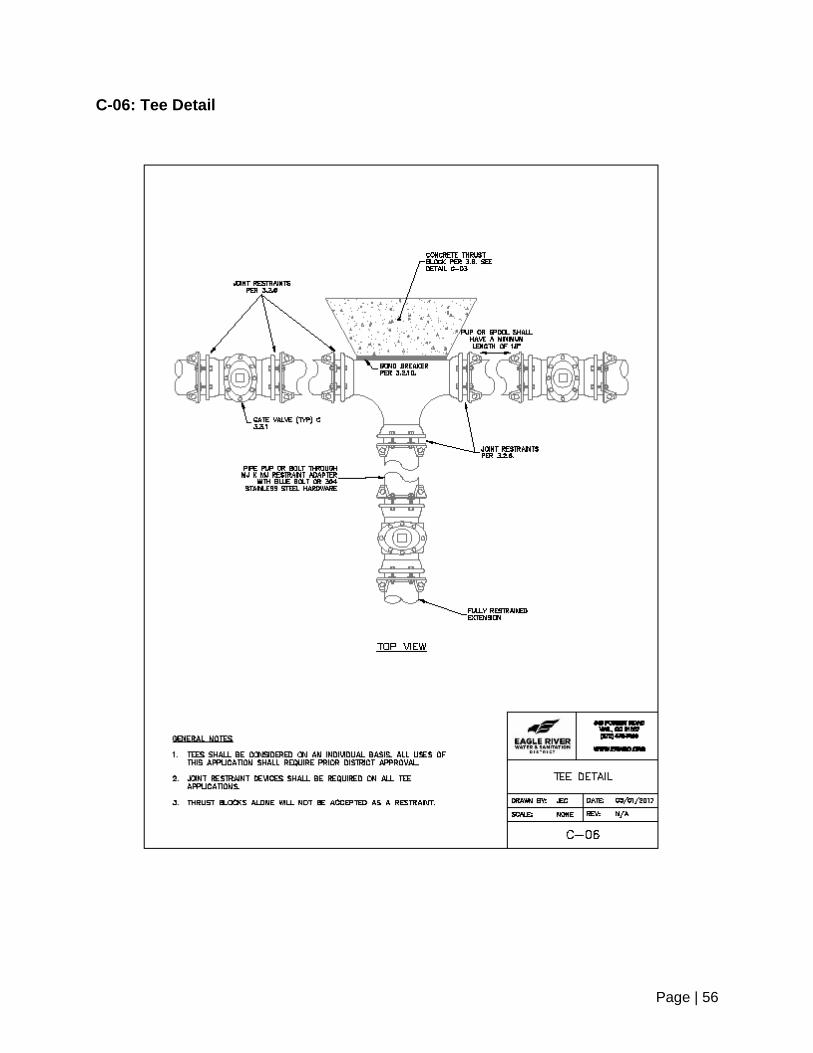
Page | 56
C-06: Tee Detail
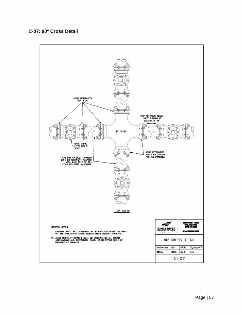
Page | 57
C-07: 90° Cross Detail

Page | 58
C-08: Fire Hydrant Assembly
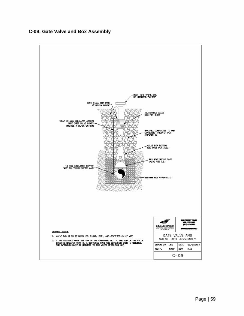
Page | 59
C-09: Gate Valve and Box Assembly

Page | 60
C-10 Anchor Block Cutoff Collar

Page | 61
C-11: Groundwater Barrier

Page | 62
C-12: Waterline Casing Detail

Page | 63
C-13: Polyethylene Wrap
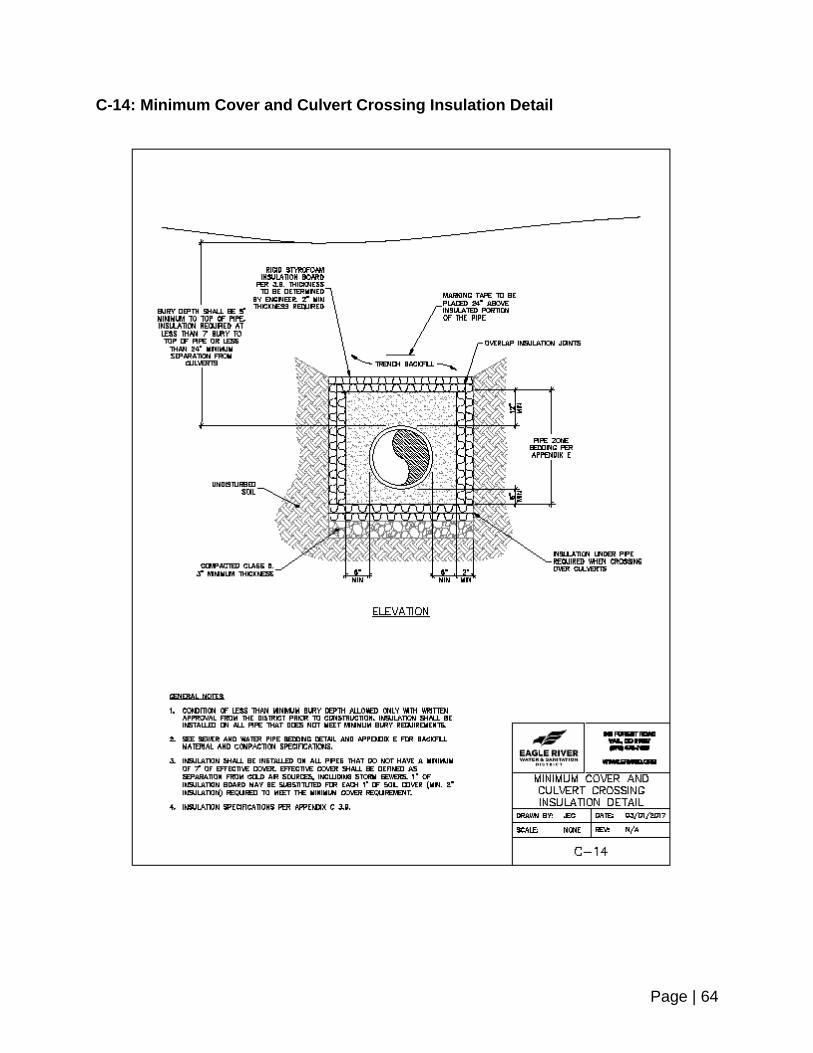
Page | 64
C-14: Minimum Cover and Culvert Crossing Insulation Detail
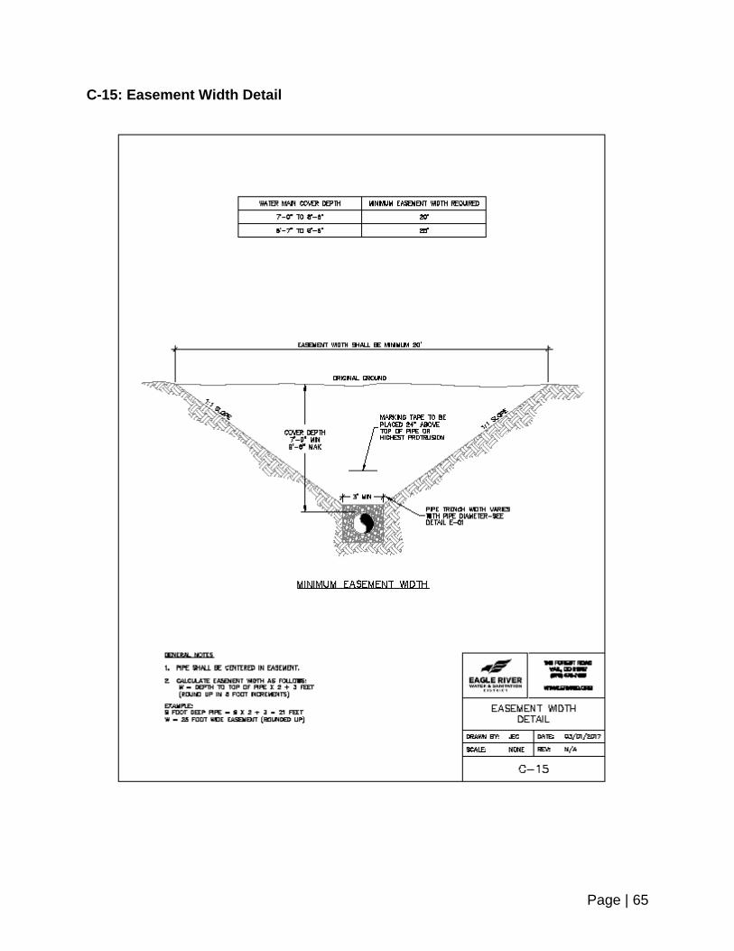
Page | 65
C-15: Easement Width Detail