appendix c airworthiness qualification …...airworthiness qualification specification (aqs) for...
TRANSCRIPT
Appendix C
AIRWORTHINESS QUALIFICATION REQUIREMENTS
NAV EQUIPMENT
DISTRIBUTION STATEMENT A. Approved for public release. Distribution is unlimited.
ADS-88-HDBK
DISTRIBUTION STATEMENT A. Approved for public release, distribution is unlimited.
AERONAUTICAL DESIGN STANDARD GUIDANCE HANDBOOK
NAVIGATION EQUIPMENT
CCDC Aviation & Missile Center Aviation Engineering Directorate
Mission Equipment Division Redstone Arsenal, AL
20 September 2018
Dr. Melvin Johnson Chief, Avionics Architecture Branch Mission Equipment Division
Dr. Yolanda Powell-Friend Chief, Mission Equipment Division CCDC Aviation & Missile CenterAviation Engineering Directorate

ADS-88-HDBK
ii
CONTENTS
Paragraph Page
1 SCOPE ....................................................................................................................................... 1
1.1 Scope. ................................................................................................................................. 1
1.2 Classification. ..................................................................................................................... 1
1.3 Intended Use. ..................................................................................................................... 1
2 APPLICABLE DOCUMENTS .................................................................................................. 2
2.1 General................................................................................................................................ 2
2.2 Government documents. .................................................................................................. 2
2.2.1 Specifications, standards, and handbooks. ........................................................... 2
2.2.2 Other government documents, drawings, and publications. ............................... 3
2.3 Non-government publications. ......................................................................................... 4
3 REQUIREMENTS ..................................................................................................................... 5
3.1 Automatic Direction Finder (ADF) ................................................................................... 5
3.1.1 Airspace Interface ...................................................................................................... 5
3.1.2 Range ........................................................................................................................... 6
3.1.3 Accuracy ...................................................................................................................... 6
3.2 Instrument Landing System (ILS) and Very High Frequency (VHF) Omni-Range (VOR) ......................................................................................................................................... 6
3.2.1 Airspace Interface ...................................................................................................... 7
3.2.2 Range ........................................................................................................................... 7
3.2.3 Accuracy ...................................................................................................................... 8
3.3 Tactical Air Navigation (TACAN) ..................................................................................... 8
3.3.1 Tactical Interface ........................................................................................................ 8
3.3.2 Airspace Interface ...................................................................................................... 9
3.3.3 Range ......................................................................................................................... 10
3.3.4 Accuracy .................................................................................................................... 10
3.4 Database - System .......................................................................................................... 10
3.5 Inertial Navigation Systems (INS) ................................................................................. 11
3.5.1 Tactical Interface ...................................................................................................... 11
3.5.2 Accuracy .................................................................................................................... 13
3.6 Global Positioning System (GPS) - Supplemental ..................................................... 13
3.6.1 Tactical Interface ...................................................................................................... 13
3.6.2 Airspace Interface .................................................................................................... 16

ADS-88-HDBK
iii
3.6.3 Accuracy .................................................................................................................... 16
3.7 Global Positioning System (GPS) – Space Based Augmentation System (SBAS)................................................................................................................................................... 17
3.7.1 Airspace Interface .................................................................................................... 17
3.7.2 Navigation Warfare .................................................................................................. 17
3.7.3 Accuracy .................................................................................................................... 17
3.8 Required Navigation Performance (RNP) ................................................................... 17
3.8.1 Airspace Interface .................................................................................................... 18
4 AIRWORTHINESS QUALIFICATION .................................................................................. 18
4.1 Automatic Direction Finder (ADF) ................................................................................. 18
4.1.1 Airspace Interface .................................................................................................... 18
4.1.2 Range ......................................................................................................................... 18
4.1.3 Accuracy .................................................................................................................... 19
4.2 Instrument Landing System (ILS) and Very High Frequency (VHF) Omni-Range (VOR) ....................................................................................................................................... 19
4.2.1 Airspace Interface .................................................................................................... 20
4.2.2 Range ......................................................................................................................... 20
4.2.3 Accuracy .................................................................................................................... 21
4.3 Tactical Air Navigation (TACAN) ................................................................................... 21
4.3.1 Tactical Interface ...................................................................................................... 21
4.3.2 Airspace Interface .................................................................................................... 21
4.3.3 Range ......................................................................................................................... 22
4.3.4 Accuracy .................................................................................................................... 22
4.4 Database - System .......................................................................................................... 23
4.4.1 System Qualification ................................................................................................ 23
4.4.2 Database Qualification Process ............................................................................. 23
4.5 Inertial Navigation Systems (INS) ................................................................................. 24
4.5.1 Tactical Interface ...................................................................................................... 24
4.5.2 Accuracy .................................................................................................................... 25
4.6 Global Positioning System (GPS) - Supplemental ..................................................... 25
4.6.1 Tactical Interface ...................................................................................................... 26
4.6.2 Airspace Interface .................................................................................................... 26
4.6.3 Accuracy .................................................................................................................... 26
4.7 Global Positioning System (GPS) - Space Based Augmentation System (SBAS) 26
4.7.1 Airspace Interface .................................................................................................... 26

ADS-88-HDBK
iv
4.7.2 Navigation Warfare .................................................................................................. 27
4.7.3 Accuracy .................................................................................................................... 27
4.8 Required Navigation Performance (RNP) ................................................................... 27
4.8.1 Airspace Interface .................................................................................................... 27
5 NOTES ..................................................................................................................................... 29
5.1 Intended use. .................................................................................................................... 29
5.2 Changes from previous issue. ....................................................................................... 30
5.3 Helicopter specific guidance. ......................................................................................... 30
5.3.1 Definitions .................................................................................................................. 30
5.3.2 Radio Presets ........................................................................................................... 30
5.3.3 Automatic Direction Finder (ADF) .......................................................................... 31
CONTENTS
Table Page
TABLE I. Navigation capabilities - ADF .................................................................................... 5 TABLE II. Range - ADF ............................................................................................................... 6
TABLE III. Accuracy - ADF bearing ........................................................................................... 6
TABLE IV. Navigation capabilities - VOR & ILS ...................................................................... 6
TABLE V. LOC & GS Frequency Pairs (MHz) ......................................................................... 7
TABLE VI. Navigation capabilities - TACAN ............................................................................ 8
TABLE VII. Navigation capabilities - INS ................................................................................ 11
TABLE VIII. Accuracy - INS ...................................................................................................... 12 TABLE IX. Navigation capabilities - GPS (supplemental) ................................................... 13
TABLE X. Navigation capabilities – GPS (SBAS) ................................................................. 17
TABLE XI. Navigation capabilities – RNP .............................................................................. 17
TABLE XII. Test frequencies - ADF ........................................................................................ 19

ADS-88-HDBK
1
1 SCOPE
1.1 Scope.
a. This handbook provides guidance material for the airworthiness approval ofinstalled navigation equipment for Army aircraft systems including Unmanned Aircraft Systems (UAS).
b. This handbook is for guidance only and cannot be cited as a requirement. Thishandbook describes an acceptable means, but not the only means, to comply with applicable regulations.
c. The guidance in this handbook cannot ensure compliance with laws andregulations of the US Army airworthiness regulations or other host nation airspace entry regulations for every possible installation configuration. The applicant remains responsible for regulatory compliance and should work closely with their aircraft airworthiness qualification office and airspace coordination office to ensure regulatory compliance. For the Army, these offices are listed in Army Regulation 70-62 and 95-2.
d. This handbook provides guidance information intended for new approvals. Thishandbook is not intended to modify, change or cancel existing equipment design or airworthiness approvals. Configurations of equipment with existing airworthiness approvals can continue to be installed within the provisions of their original design and airworthiness qualification.
1.2 Classification.
Positioning and navigation equipment may be used for a variety of functions such as navigation, automatic dependent surveillance, and/or obstacle/terrain awareness and warning systems.
a. This document addresses navigation equipment for navigation only.
b. Other use may have additional requirements upon the navigation equipment notacknowledged within this document.
1.3 Intended Use.
a. This ADS is intended to be used as a tailorable guidance for use in anAirworthiness Qualification Plan (AQP), Statement of Work (SOW), and other relevant airworthiness documents. For example, 3.1 requirements could be inserted into an aircraft specification when selecting automatic direction finding navigation as a capability and the associated 4.1 could be directly put into a AQP or SOW for airworthiness and verification.
b. System level requirements, including safety, environmental, and drawings, whichare allocated to navigation functions are not fully included in this document but are still allocated requirements to be complied with and have airworthiness SOW and

ADS-88-HDBK
2
deliverables for navigation airworthiness. Generally this effort is covered by the system level requirements and SOW.
c. Lower level requirements particular to an implementation like electronichardware, software, or other technology are implementation allocated technology requirements to be complied with and have airworthiness SOW and deliverables for navigation airworthiness. Generally this design specific effort is documented in the Airworthiness Qualification Specification (AQS) for approval.
d. AR95-1 defines US Army aviation operational requirements. AR95-2 definesmilitary tactical and civil US Army airspace requirements. AR 70-62 defines the airworthiness qualification process or aircraft and equipment intended for use in all airspace and operational environments. Demonstrated performance is the key criteria of qualification. Update of and approval of system specification document(s) and manuals to reflect actual representative demonstrated performance attainable when used in accordance with approved manuals facilitates issuance of SAQ and supports issuance of airworthiness release for flight.
e. Prior qualified components and systems may be accepted in cases proposed asQualification by Analysis. This may reduce or eliminate testing depending on the provided information attributed to similarities.
2 APPLICABLE DOCUMENTS
2.1 General.
The documents listed below are not necessarily all of the documents referenced herein, but are those needed to understand the information provided by this handbook.
2.2 Government documents.
2.2.1 Specifications, standards, and handbooks.
The following specifications, standards, and handbooks form a part of this document to the extent specified herein.
DEPARTMENT OF DEFENSE
(Copies of these documents are available online at http://assist.daps.dla.mil/quicksearch/ or from the Standardization Document Order Desk, 700 Robbins Avenue, Building 4D, Philadelphia, PA 19111-5094.)
AIMS 03-1000B Technical Standard for the ATCRBS/IFF/Mark XIIA Electronic Identification System and Military Implementation of Mode S
(Order AIMS documents from the DoD International AIMS Program Office, 450 Third Street Building #323, Robins AFB, GA 31098.)
ADS-88-HDBK
3
ICD-GPS-060 Precise-Time and Time-Interval (PTTI) Interface
ICD-GPS-200 NAVSTAR GPS Space Segment/Navigation User Interfaces
ICD-GPS-700 NAVSTAR GPS Military-Unique Space Segment/User Segment Interfaces
IS-GPS-099 Interface Specification for NAVSTAR Global Positioning System Advanced Digital Antenna Production (ADAP)
IS-GPS-153 GPS User Equipment Interface Control Document for the RS-232/RS-422 Interface for the DoD Standard GPS UE Radio Receivers
IS-GPS-200 NAVSTAR GPS Space Segment/Navigation User Interfaces
IS-GPS-800 NAVSTAR GPS Space Segment/User Segment L1C Interface
SS-GPS-001 NAVSTAR Global Positioning System (GPS) Selective Availability Anti-Spoofing Module (SAASM) System Specification
SS-GPS-300 System Specification for the NAVSTAR Global Positioning System
(Order GPS documents from the Global Positioning Systems Directorate, Los Angeles AFB, CA.)
DEPARTMENT OF TRANSPORTATION
TSO-C115b TSO-C115b, Airborne Area Navigation Equipment Using Multi-Sensor Inputs, 30 Sep 1994
TSO-C129a TSO-C129a, Airborne Supplemental Navigation Equipment Using Global Positioning System (GPS), 20 Feb 1996
(Copies of these documents are available online at http://rgl.faa.gov/ or from Federal Aviation Administration, 800 Independence Ave., S.W., Washington, DC 20591.)
2.2.2 Other government documents, drawings, and publications.
The following other Government documents, drawings, and publications form a part of this document to the extent specified herein.
DEPARTMENT OF THE ARMY
ADS-70-HDBK Airworthiness Guidance for Integration of Radio Communications, Radar Surveillance / Identification Friend or Foe, Datalink
ADS-88-HDBK
4
(Copies of these documents are available from the Commander, U.S. Army Combat Capabilities Development Command, Aviation & Missile Center FCDD-AE, Huntsville, AL 35898.)
DEPARTMENT OF TRANSPORTATION
AC 00-31 United States (U.S.) National Aviation Standard for the Very High Frequency Omnidirectional Radio Range (VOR)/Distance Measuring Equipment (DME)/Tactical Air Navigation (TACAN) Systems
AC 20-138 Airworthiness Approval of Positioning and Navigation Systems
AC 20-153 Acceptance of Data Processes and Associated Navigation Databases
AC 20-165 Airworthiness Approval of Automatic Dependent Surveillance - Broadcast OUT Systems
AC 29-2 Certification of Transport Category Rotorcraft
(Copies of these documents are available online at http://rgl.faa.gov/ or from Federal Aviation Administration, 800 Independence Ave., S.W., Washington, DC 20591.)
2.3 Non-government publications.
The following documents from a part of this document to the extent specified herein.
RTCA
DO-143 Minimum Performance Standards—Airborne Radio Marker receiving Equipment Operating on 75 Megahertz
DO-179 Minimum Operating Performance Standards for Automatic Direction Finding (ADF) Equipment
DO-187 Minimum Operational Performance Standards for Airborne Area Navigation Equipment Using Multi-Sensor Inputs
DO-189 Minimum Operational Performance Standards for Airborne Distance Measuring Equipment (DME) Operating within the Radio Frequency Range of 960-1215 Megahertz
DO-192 Minimum Operational Performance Standards for Airborne ILS Glide Slope Receiving Equipment Operating Within the Radio Frequency Range of 328.6-335.4 MHz

ADS-88-HDBK
5
DO-195 Minimum Operational Performance Standards for Airborne ILS Localizer Receiving Equipment Operating Within the Radio Frequency Range of 108-112 MHz
DO-196 Minimum Operational Performance Standards for Airborne VOR Receiving Equipment Operating Within the Radio Frequency Range of 108-117.95 MHz
DO-200 Standards for Processing Aeronautical Data
DO-229 Minimum Operational Performance Standards for Global Positioning System/Satellite-Based Augmentation System Airborne Equipment
DO-236 Minimum Aviation System Performance Standards: Required Navigation Performance for Area Navigation
DO-316 Minimum Operational Performance Standards for Global Positioning System/Aircraft Based Augmentation System Airborne Equipment
(Order RTCA documents from RTCA Inc., 1150 18th Street NW, Suite 910, Washington, D.C. 20036. Telephone (202) 833-9339, fax (202) 833-9434. You can also order copies online at www.rtca.org.)
ICAO
Aircraft Operations Volume I Flight Procedures, Fifth edition
(Order ICAO documents from International Civil Aviation Organization, 999 Robert-Bourassa Boulevard, Montréal, Quebec H3C 5H7, Canada. Telephone (514) 954-8219, fax (514) 954-6077. You can also order copies online at www.icao.int.)
3 REQUIREMENTS
3.1 Automatic Direction Finder (ADF)
The system shall provide the following navigation capabilities with Civil and Military Features IAW TABLE I of this document.
TABLE I. Navigation capabilities - ADF
Navigation Capabilities Civil Features Tactical Features ADF En-route, terminal, and
non-precision approach navigation
Same as Civil Features but with extended frequency range
3.1.1 Airspace Interface
ADS-88-HDBK
6
The navigation system shall comply with the Global Air Traffic Management (GATM) airspace Minimum Performance Standards (MPS) for ADF function IAW Category A of RTCA DO-179 section 2.2 as modified by TSO C41d section a(1) or latest revision and modified for the intercommunication system specified for the aircraft.
3.1.2 Range
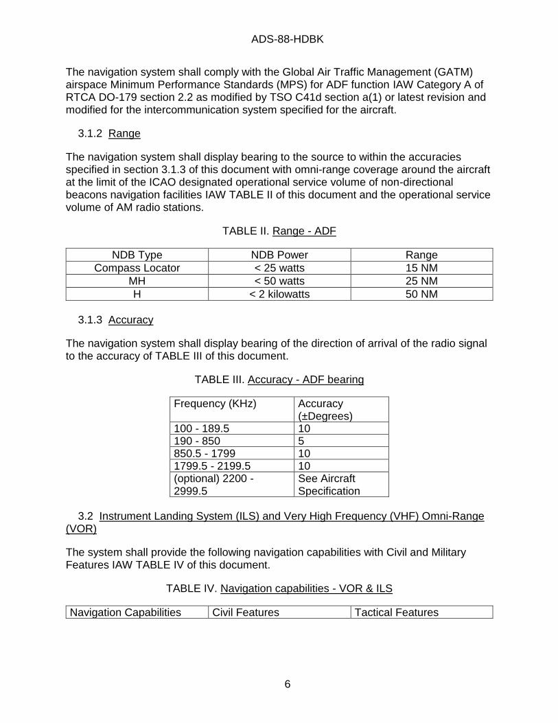
The navigation system shall display bearing to the source to within the accuracies specified in section 3.1.3 of this document with omni-range coverage around the aircraft at the limit of the ICAO designated operational service volume of non-directional beacons navigation facilities IAW TABLE II of this document and the operational service volume of AM radio stations.
TABLE II. Range - ADF
NDB Type NDB Power Range
Compass Locator < 25 watts 15 NM
MH < 50 watts 25 NM
H < 2 kilowatts 50 NM
3.1.3 Accuracy
The navigation system shall display bearing of the direction of arrival of the radio signal to the accuracy of TABLE III of this document.
TABLE III. Accuracy - ADF bearing
Frequency (KHz) Accuracy (±Degrees)
100 - 189.5 10 190 - 850 5 850.5 - 1799 10 1799.5 - 2199.5 10 (optional) 2200 - 2999.5
See Aircraft Specification
3.2 Instrument Landing System (ILS) and Very High Frequency (VHF) Omni-Range (VOR)
The system shall provide the following navigation capabilities with Civil and Military Features IAW TABLE IV of this document.
TABLE IV. Navigation capabilities - VOR & ILS
Navigation Capabilities Civil Features Tactical Features
ADS-88-HDBK
7
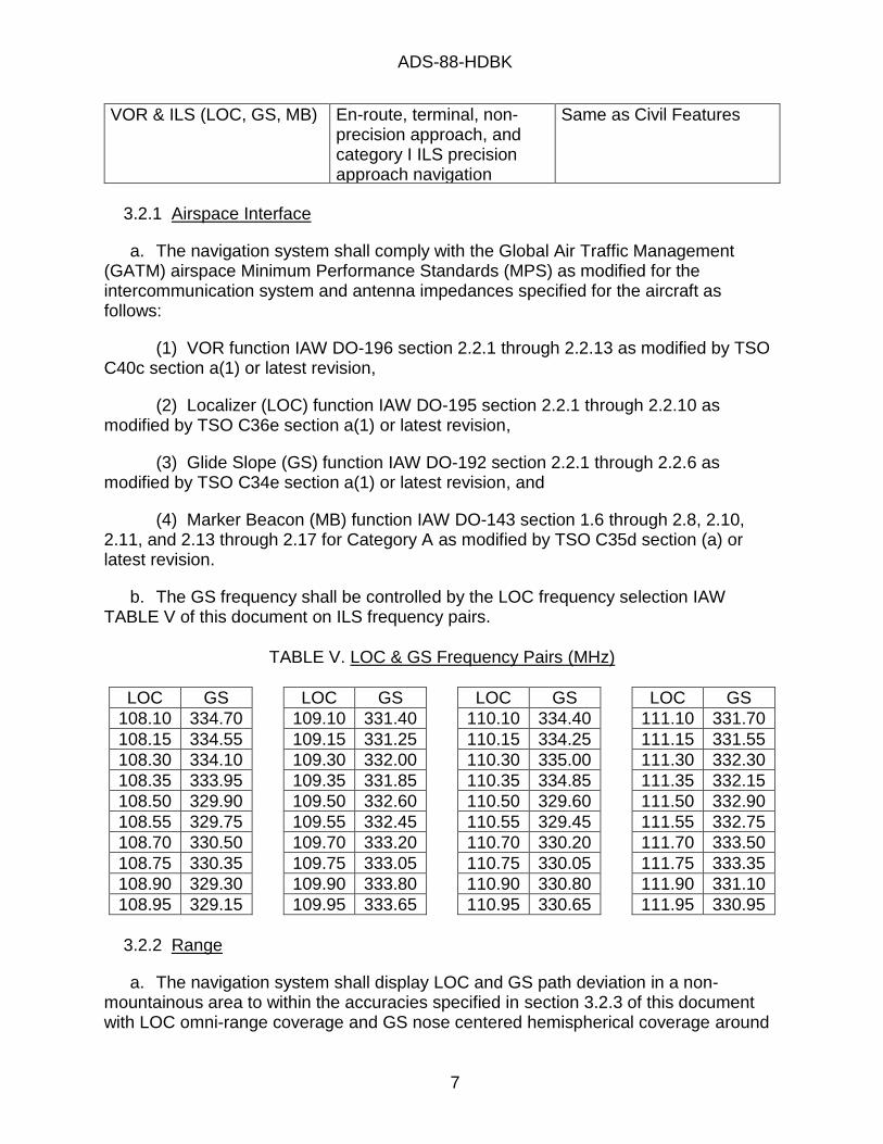
VOR & ILS (LOC, GS, MB) En-route, terminal, non-precision approach, and category I ILS precision approach navigation
Same as Civil Features
3.2.1 Airspace Interface
a. The navigation system shall comply with the Global Air Traffic Management(GATM) airspace Minimum Performance Standards (MPS) as modified for the intercommunication system and antenna impedances specified for the aircraft as follows:
(1) VOR function IAW DO-196 section 2.2.1 through 2.2.13 as modified by TSOC40c section a(1) or latest revision,
(2) Localizer (LOC) function IAW DO-195 section 2.2.1 through 2.2.10 asmodified by TSO C36e section a(1) or latest revision,
(3) Glide Slope (GS) function IAW DO-192 section 2.2.1 through 2.2.6 asmodified by TSO C34e section a(1) or latest revision, and
(4) Marker Beacon (MB) function IAW DO-143 section 1.6 through 2.8, 2.10,2.11, and 2.13 through 2.17 for Category A as modified by TSO C35d section (a) or latest revision.
b. The GS frequency shall be controlled by the LOC frequency selection IAWTABLE V of this document on ILS frequency pairs.
TABLE V. LOC & GS Frequency Pairs (MHz)
LOC GS
108.10 334.70
108.15 334.55
108.30 334.10
108.35 333.95
108.50 329.90
108.55 329.75
108.70 330.50
108.75 330.35
108.90 329.30
108.95 329.15
LOC GS
109.10 331.40
109.15 331.25
109.30 332.00
109.35 331.85
109.50 332.60
109.55 332.45
109.70 333.20
109.75 333.05
109.90 333.80
109.95 333.65
LOC GS
110.10 334.40
110.15 334.25
110.30 335.00
110.35 334.85
110.50 329.60
110.55 329.45
110.70 330.20
110.75 330.05
110.90 330.80
110.95 330.65
LOC GS
111.10 331.70
111.15 331.55
111.30 332.30
111.35 332.15
111.50 332.90
111.55 332.75
111.70 333.50
111.75 333.35
111.90 331.10
111.95 330.95
3.2.2 Range
a. The navigation system shall display LOC and GS path deviation in a non-mountainous area to within the accuracies specified in section 3.2.3 of this document with LOC omni-range coverage and GS nose centered hemispherical coverage around

ADS-88-HDBK
8
the aircraft at the limit of the ICAO designated operational service volume of Glide Slope navigation facilities, and of Localizer navigation facilities at least to the maximum certificated aircraft altitude.
b. The navigation system shall display VOR bearing from station and course deviation in a non-mountainous area to within the accuracies specified in section 3.2.3 of this document with omni-range coverage around the aircraft at the limit of the ICAO designated operational service volume of VOR navigation facilities at least to the maximum certificated aircraft altitude.
c. The navigation system shall display MB modulation color and provide the station code, with lower hemi-spherical coverage around the aircraft at attitudes of at least to 45 degrees, from the limit of the ICAO designated operational service volume of the MB navigation facilities, and at least to the maximum certificated aircraft altitude through over flight of the MB station.
3.2.3 Accuracy
The navigation system shall display on deviation indicators within the following centering errors:
a. VOR shall not exceed 6 degrees from the selected course,
b. LOC shall not exceed 11% of full scale deflection, and
c. GS shall not exceed 13% of full scale deflection.
3.3 Tactical Air Navigation (TACAN)
The system shall provide the following navigation capabilities with Civil and Military Features IAW TABLE VI of this document.
TABLE VI. Navigation capabilities - TACAN
Navigation Capabilities Civil Features Tactical Features TACAN En-route, terminal, and
non-precision approach navigation
Air-to-Air distance, & same as civil features
3.3.1 Tactical Interface
The navigation system shall compute bearing, distance, station identification, distance rate (velocity), and time-to-station information relative to an airborne and surface beacon using the standard TACAN signal defined IAW MIL-STD-291C sections 4 and 5 or latest revision except:
a. Section 5.14 tolerances of ±0.5µs shall be ±0.1µs, and
ADS-88-HDBK
9
b. Surface beacons shall have a Morse coding of a lower limit dot duration of 100ms, and shall comply with AC 00-31A or latest revision paragraphs 30a(2), 30a(3), 124a, 126a, 135, and 139.
3.3.1.1 Modes
The navigation system shall at least perform X and Y channel air-to-ground modes and X and Y channel air-to-air modes.
3.3.1.2 Manual Transmission Suppression
The navigation system shall suppress all MIL-STD-291 interrogations and air-to-air reply transmissions in all modes during manual transmission suppression.
3.3.1.3 IFF Suppression Interface
The navigation system shall have at least a single input/output suppression interface complying with DoD AIMS 03-1000B paragraph 4.7.31.1 and 4.7.31.2 or latest revision.
3.3.1.4 Distance Accuracy
The system shall have a slant range distance error no greater than 0.1NM for ranges less than 300NM under static and dynamic conditions of DO-189 2.2.1c and 2.2.1d and over a signal level from 0 dBm to -91 dBm at reply efficiencies of 60 percent.
3.3.1.5 Bearing Accuracy
a. The system shall have a bearing error no greater than 0.5 degrees under static and dynamic conditions of DO-189 2.2.1c and 2.2.1d and over a signal level from 0 dBm to -85 dBm.
b. The system shall have a bearing error no greater than 3 degrees under static and dynamic conditions of DO-189 2.2.1c and 2.2.1d and over a signal level from 0 to -91 dBm with 135Hz decode warning flagged.
3.3.1.6 Diversity Antenna Interface (optional)
Reserved
3.3.2 Airspace Interface
The navigation system shall comply with the Global Air Traffic Management (GATM) airspace Minimum Performance Standards (MPS) for:
a. TACAN air-to-ground distance function and Distance Measurement Equipment (DME) function IAW RTCA DO-189 section 2.2 as modified by TSO C66c section a(1) or latest revision except the distance accuracy of ±0.17NM or ±0.25% of the distance within section 2.2.1 is replaced by ±0.1NM or ±0.033% of the distance, section 2.2.3 is replaced by MIL-STD-291C section 5.13, section 2.2.4 is replaced by MIL-STD-291C

ADS-88-HDBK
10
section 5.14 as modified by paragraph 3.3.1 of this document, section 2.2.5 tracking of 16 pp/s per frequency shall be 30 pp/s per frequency except as a test condition for other section of 2.2 performance with pp/s dependencies, and section 2.2.7.1 output power shall be replaced with at least 27dBw, and
b. TACAN air-to-ground bearing function and TACAN identification function IAW AC00-31A paragraphs 189 through 191 or latest revision with a separate bearing memoryfrom the distance memory, on-code undesirable signal rejection IAW AC 00-31A section29a or latest revision, off-code on-frequency undesirable signal rejection from an air-to-ground TACAN station at least +20dB greater than the desired signal in the presence of3600 pp/s random fruit while the receiver is in distance warning, and accuracy persection 3.3.1.5 of this document.
3.3.2.1 Paired Channel Support
For systems with VOR/ILS, the system shall have a mode to be capable of TACAN/DME channel selection from the VOR/ILS frequency control with the VOR/ILS pairs stated in RTCA DO-189 Appendix A.
3.3.2.2 Scanning TACAN Interface (optional)
Reserved
3.3.3 Range
The navigation system shall display slant range distance, bearing from station, and course deviation in a non-mountainous area to within the accuracies specified in section 3.3.4 of this document with omni-range coverage around the aircraft at the limit of the ICAO designated operational service volume of TACAN navigation facilities at least to the maximum certificated aircraft altitude.
3.3.4 Accuracy
3.3.4.1 Distance Accuracy
The navigation system shall display slat range distance to the station with an error less than 0.5NM with inspected TACAN and DME stations compliant with AC 00-31A or latest revision.
3.3.4.2 Bearing Accuracy
The navigation system shall display bearing from station and deviation from the selected course with an error less than 4.5 degrees with inspected TACAN stations compliant with AC 00-31A or latest revision.
3.4 Database - System

ADS-88-HDBK
11
a. The system shall perform its intended functions with a Type 2 Letter of Authorization (LOA) issued database IAW RTCA/DO-200B and AC 20-153B or latest revisions.
b. The system shall not corrupt the database and shall verify and notify the operator of any Data Quality Requirement issues (e.g. integrity failure (bad CRC), timeliness failure (out of date)).
3.5 Inertial Navigation Systems (INS)
The system shall provide the following navigation capabilities with Civil and Military Features IAW TABLE VII of this document.
TABLE VII. Navigation capabilities - INS
Navigation Capabilities Civil Features Tactical Features INS Same as Tactical Features En-route and terminal
navigation 3.5.1 Tactical Interface
3.5.1.1 Alignment Modes
The navigation system shall be capable of Gyro Compass (GC), Stored, Ship, and Air alignments to initialize the INS at the performance of section 3.5.2 of this document.
3.5.1.1.1 Gyro Compass (GC)
The navigation system shall be capable of Gyro Compass (GC) alignments with an aircraft not moving in all 6 degrees of freedom from start to finish of GC alignment except for aircraft vibration.
a. The navigation system shall accept the operator entered GC initialization of position with an accuracy within 0.5NM including any selected position from a valid RNAV system, then
b. The navigation system shall complete a GC alignment within the larger of 4 or 4*cosine(60 degrees)/cosine(latitude) minutes between the latitudes of 80 degrees North and 80 degrees South.
c. The navigation system shall complete the alignment using an air alignment if the GC alignment is interrupted by aircraft movement, or by a weight off wheels indication from the aircraft platform.
3.5.1.1.2 Stored

ADS-88-HDBK
12
The navigation system shall be capable of Stored alignments with an aircraft not moving in all 6 degrees of freedom from last aircraft shutdown to finish of Stored alignment except for aircraft vibrations.
3.5.1.1.3 Ship
The navigation system shall be capable of Ship alignments with the aircraft moving in one constant velocity vector with 6 degrees of freedom low to high frequency oscillation for sea state. The navigation system shall accept the operator entered ship initialization of ship position and speed vector with an accuracy within 0.25NM, 0.1 knots and 0.1 degrees including any selected initialization set from a valid RNAV system.
3.5.1.1.4 Air
The navigation system shall be capable of Air alignments with an aircraft moving and stationary in 6 degrees of freedom from start to finish of alignment. The navigation system shall accept the selected initialization reference from a valid RNAV system.
3.5.1.2 Airspace Interface
The navigation system shall comply with the Global Air Traffic Management (GATM) airspace Minimum Performance Standards (MPS) for INS function IAW RTCA DO-187 section 2.1 and 2.2 as modified by TSO C115b a(2), a(5), and a(6) for at least "TO-TO" en-route and terminal navigation equipment and with the following exceptions:
3.5.1.2.1 Holding
In addition to TSO C115b a(2)(ix), add the following requirement: The holding pattern maneuvering shall at least support all manual time based holding with course selection and TO-FROM and course deviation indications at the holding waypoint.
3.5.1.2.2 Accuracy
In lieu of Table 2-1 of RTCA/DO-187, substitute TABLE VIII of this document:
TABLE VIII. Accuracy - INS
Error Type En-Route Remote Area
En-Route Random Routes
En-Route (J/V
Routes)
Terminal
Supported Leg Length (NM)
1100 300 300 150
Equipment (NM) 19.8 3.8 2.8 1.7 FTE (NM) 2.0 1.0 1.0 1.0 Total (NM) 20.0 4.0 3.0 2.0
Note: The equipment error type includes Total System Error as defined in RTCA/DO-236B paragraph 2.1.1 except FTE. This includes path definitions of RTCA/DO-236B paragraph 3.2.3.1 for the initial flight plan fix, paragraph 3.2.3.2 for the following fixes,
ADS-88-HDBK
13
paragraphs 3.2.3.8 and 3.4.4.2 for the direct-to function, and section 3.2.5 path error terms.
3.5.1.2.3 Fly-over Waypoint Position Update
The navigation system shall be capable of manual operator initiated INS position updates from manually entered positions, waypoints in the non-corruptible database, and waypoints in the user defined database (e.g. flight plan). The equipment error during fly-over waypoint position update can be assumed to be 0.1NM.
3.5.1.2.4 RNAV Position Update
The navigation system shall be capable of manual operator initiated INS position updates from a selected valid RNAV system or position update computation system (e.g. DME/DME, TACAN).
3.5.1.2.5 Automatic Position Update (option)
The navigation system shall be capable of automated INS position updates from other sensors IAW RTCA DO-187 as modified by TSO C115b for systems with multiple sensors.
3.5.2 Accuracy
The navigation system shall compute position from last position update within 0.8NM 50% Circular Error Probability (CEP) per hour.
3.6 Global Positioning System (GPS) - Supplemental
The system shall provide the following navigation capabilities with Civil and Military Features IAW TABLE IX of this document.
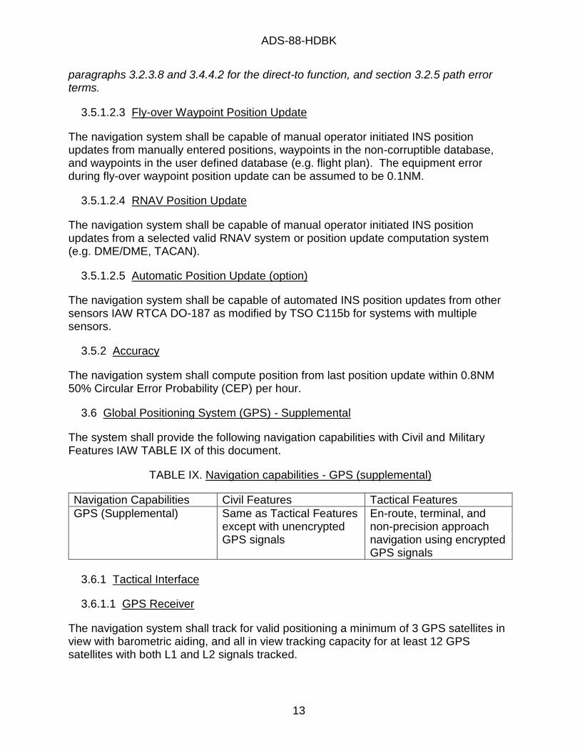
TABLE IX. Navigation capabilities - GPS (supplemental)
Navigation Capabilities Civil Features Tactical Features
GPS (Supplemental) Same as Tactical Features except with unencrypted GPS signals
En-route, terminal, and non-precision approach navigation using encrypted GPS signals
3.6.1 Tactical Interface
3.6.1.1 GPS Receiver
The navigation system shall track for valid positioning a minimum of 3 GPS satellites in view with barometric aiding, and all in view tracking capacity for at least 12 GPS satellites with both L1 and L2 signals tracked.
ADS-88-HDBK
14
3.6.1.1.1 Barometric Aiding
The navigation system shall use barometric aiding for position and Fault Detection and Exclusion (FDE) as a minimum IAW RTCA DO-316 Appendix G. The navigation system shall use pressure altitude data corrected for local barometric pressure setting (QNH) for tactical Non-Precision Approach GPS position and FDE.
3.6.1.1.2 Modes
The navigation system shall perform GPS position, time, and navigation in the following modes:
a. Encrypted Precise Positioning Service (PPS) Mode:
i. Whenever the equipment has been keyed with valid PPS keys, the equipment shall operate in the Encrypted PPS mode unless otherwise commanded by the operator.
ii. All GPS direct encrypted code Satellite Vehicle (SV) acquisition, position, navigation, time, and integrity related information shall be derived exclusively from the M or Y code modulated signals IAW ICD-GPS-700D and IS-GPS-200J or latest revision. The default selection shall be M code only.
The Y code direct SV acquisition and reacquisition may require a clock meeting the time uncertainty requirement associated with Hot Start.
iii. The navigation system shall be SAASM compliant IAW SS-GPS-001A or latest revision.
iv. When enabled by operator selection, non-direct encrypted code SV acquisition or reacquisition shall be IAW IS-GPS-200J or latest revision.
b. Standard Positioning Service (SPS) Mode:
i. All GPS related information shall be derived IAW RTCA/DO-316 section 2.1.1.2 except IS-GPS-200D shall be IS-GPS-200J or latest revision, other SPS signals may be used, and multiple frequency measurement of GPS parameters may be used per IS-GPS-200J or latest revision.
ii. SPS code modulated signals shall consist of at least L1 C/A code signal of IS-GPS-200H or latest revision.
Other SPS signals include L2 C/A, L1C signal of IS-GPS-800E or latest revision, and SPS L2C signal of IS-GPS-200J or latest revision. Satellite Base Augmentation System (SBAS) signals may be used as SPS signals as long as the SBAS system has GPS L1 or L2 frequency encoded signals and meets the requirements of DO-316 sections 2.1.1.2 and 2.1.1.3.2 using an equivalent SBAS navigation message.

ADS-88-HDBK
15
iii. The navigation system in SPS Mode shall comply with RTCA/DO-316 sections 2.1.1.5 through 2.1.1.8, and 2.1.1.10.
c. Unencrypted Mode: All GPS related information shall be derived from all supported GPS signals including PPS P signal of IS-GPS-200J or latest revision, SPS signals, and when PPS keyed, encrypted PPS signals.
3.6.1.1.3 Accuracy
The navigation system shall calculate position to the accuracy of GPS IAW SS-GPS-300E or latest revision.
3.6.1.1.4 Safety
The navigation system shall comply with RTCA/DO-316 sections 2.1.1.1.4, 2.1.1.3 through 2.1.1.4, and 2.1.1.11 through 2.1.2.2.2.5, and 2.1.2.5 through 2.1.3.6.5 except:
a. Section 2.1.1.3.1. Append new text which reads: "Additionally, GPS Satellite shall be declared UNHEALTHY when the step detector function has declared a step error until recovered by the step detection function autonomous fault detection."
b. Section 2.1.1.3.2. GPS signals may have equivalent navigation messages with different formats than IS-GPS-200D C/A navigation message bit formats used in this requirement.
c. Section 2.1.1.3.2.b and 2.1.1.3.2.c. For degraded Encrypted PPS Mode and for degraded Unencrypted Mode tactical uses, the section 2.1.1.3.2.b and 2.1.1.3.2.c unhealthy detection maybe may be set to an alternate limit by the operator but a loss of Receiver Autonomous Integrity Monitoring (RAIM) shall be annunciated.
d. Section 2.1.1.3.2.d. The alert flag unhealthy function is not required when other means of URA and instantaneous URE bounding which meet the intent is used in replacement of or in addition to the scaled URA method that the alert flag warns as possibly invalid.
e. Section 2.1.2.5 and 2.1.3.5. SAASM requirement values for dynamic tracking supersede the values of these sections when more stringent.
f. Paragraph 2.1.2.6. The navigation system shall also output VFOMP, HFOMV, VFOMV, HUL, VUL, VPL, vertical position, and vertical velocity as position output data.
3.6.1.2 GPS Hot Start
a. The navigation system shall perform a GPS hot start from an external GPS via an external interface IAW IS-GPS-153D or latest revision.
b. The navigation system shall provide GPS data via an external interface IAW IS-GPS-153D or latest revision to be perform GPS hot start to an external GPS.
ADS-88-HDBK
16
3.6.1.3 Precise Timing Interface
The navigation system shall provide Have-Quick timing to a device IAW ICD-GPS-060A or latest revision.
The interface may need controls of the precise timing interface to apply high impedance output as a means of indicating poor time figure of merit for previous HAVEQUICK interface compatibility.
3.6.1.4 Anti-Jamming Antenna
The navigation system shall include a GPS Anti-Jamming Antenna. The interface most used is IS-GPS-099H or latest revision.
3.6.2 Airspace Interface
The navigation system shall be capable of navigation IAW RTCA DO-208 section 2 as modified by TSO C129a class A1 for "TO-TO" navigation equipment and with the following exceptions.
3.6.2.1 Safety
The navigation system shall be safe with the following Failure Condition Classifications.
a. Failure of the function defined in TSO C129a causing misleading information is a major failure condition for oceanic/remote, en route and terminal navigation, and lateral navigation (LNAV) approaches.
b. Loss of the function defined in TSO C129a is a minor failure condition for oceanic/remote, en route and terminal navigation, and LNAV approaches.
3.6.2.2 GPS Receiver
The navigation system shall use the GPS Receiver of Section 3.6.1.1 of this document in all modes.
The GPS receiver should support building all the functions required in TSO C129a. Examples include FDE outputs to support RAIM requirements, FDE prediction outputs to support RAIM prediction requirements, and GPS position outputs.
3.6.2.3 Holding
In addition to TSO C129a a(3)(xi)2b, add the following requirement: The holding pattern maneuvering shall at least support all manual time based holding with TO-FROM navigation, course selection, and course deviation indications at the holding waypoint.
3.6.3 Accuracy
The navigation system shall be capable of position estimation within 16m 50% Spherical

ADS-88-HDBK
17
Error Probability (SEP) for PPS and 17m 50% SEP for SPS under the full dynamic limits of the aircraft.
3.7 Global Positioning System (GPS) – Space Based Augmentation System (SBAS)
The system shall provide the following navigation capabilities with Civil and Military Features IAW TABLE X of this document.
TABLE X. Navigation capabilities – GPS (SBAS)
Navigation Capabilities Civil Features Tactical Features GPS (SBAS) En-route, terminal, and
non-precision approach through LPV approach navigation using civil satellite signals
N/A
3.7.1 Airspace Interface
The navigation system shall comply with the Global Air Traffic Management (GATM) airspace Minimum Performance Standards (MPS) for GPS (SBAS) function IAW RTCA DO-229E for class gamma-3 equipment or latest revision as modified by TSO-C146e section 3 except paragraph 3g or latest revision, as modified by AC 20-165B or latest revision Appendix B for the additional usage as the ADS-B sensor.
It is expected that this capability will be updated to include L1C signal of IS-GPS-800E or latest revision, L2C signals of IS-GPS-200J or latest revision, and L5 signals of IS-GPS-705E or latest revision.
3.7.2 Navigation Warfare
The navigation system shall annunciate the compromise of the GPS (SBAS) function to identify the need to transition to tactical navigation systems during navigation warfare environments.
3.7.3 Accuracy
The navigation system shall be capable of position estimation within 7.6m 95% Spherical Error Probability (SEP) for the FAA Wide Area Augmentation System (WAAS) with GPS under the full dynamic limits of the aircraft.
3.8 Required Navigation Performance (RNP)
The system shall provide the following navigation capabilities with Civil and Military Features IAW TABLE XI of this document.
TABLE XI. Navigation capabilities – RNP
ADS-88-HDBK
18
Navigation Capabilities Civil Features Tactical Features RNP Same as Tactical Features RNP-0.3 through RNP-20
types 3.8.1 Airspace Interface
a. The navigation system shall comply with the Global Air Traffic Management (GATM) airspace Minimum Performance Standards (MPS) for RNP function IAW RTCA DO-236C section 2 and section 3.
b. If using Global Navigation Satellite System signals, the navigation system shall also provide an alert if the probability of Global Navigation Satellite System signal-in-space errors causing a lateral position error greater than 2X NM exceeds 10-7 per hour for RNP-X legs.
c. The navigation system shall address the operator or system execution of at least VA, VI, VM, CA, and FM leg types and fly-over turns IAW AC 20-138D section 9-3h. This includes mode displays for when RNP is armed during execution of an RNAV leg without a defined containment area.
4 AIRWORTHINESS QUALIFICATION
4.1 Automatic Direction Finder (ADF)
The following testing and analysis shall prove that the system provides the navigation capabilities with the Civil and Military Features IAW TABLE I of this document. Each test shall be have a test plan developed IAW DI-NDTI-80566, and a test report developed IAW DI-NDTI-80809 detailing the results of the test IAW the approved test plan. All navigation ground tests may be combined into a single test plan. All navigation flight tests may be combined into a single test plan.
4.1.1 Airspace Interface
Laboratory testing shall demonstrate/survey the navigation system performance IAW Category A of RTCA DO-179 section 2.2 as modified for the intercommunication system specified for the aircraft under the intended environment. The laboratory testing shall perform verification of the sub-system interfaces IAW the interface requirement specification(s). A test plan shall be developed similar to RTCA DO-179 sections 2.2 through 2.4 including equipment performance monitoring during military environmental testing.
4.1.2 Range
4.1.2.1 Antenna Coverage
The analysis may be combined. Each analysis shall be developed IAW DI-MISC-80711A or as a subset of DI-EMCS-81540, DI-EMCS-81541, and/or DI-EMCS-81542. Antenna coverage analysis and/or testing including bonding checks and system
ADS-88-HDBK
19
electromagnetic compatibility testing shall be performed IAW ADS-70 section 5.1.1.
4.1.2.2 System Ground Test and Calibration
Ground testing and calibration shall demonstrate the readiness of the ADF installation for flight testing to include any installation requirements, calibration, and installation testing from laboratory test results, reception of test signals and built in test to show correct connectivity for voice communications, station identification, and system performance at least on one frequency.
4.1.2.3 Flight Test
4.1.2.3.1 System Flight Test
Flight testing shall demonstrate/survey the voice communications, station identification, and system performance at least on one frequency IAW AC 29-2C section MG1b(7)(v)(B) through (D).
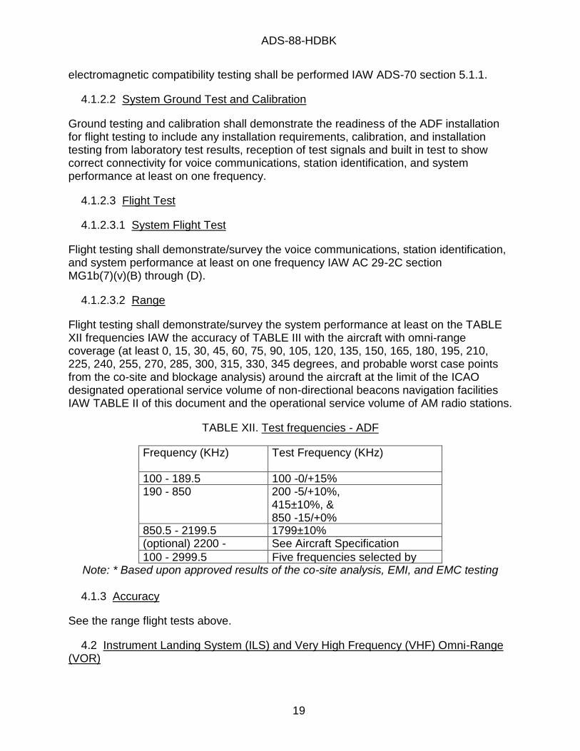
4.1.2.3.2 Range
Flight testing shall demonstrate/survey the system performance at least on the TABLE XII frequencies IAW the accuracy of TABLE III with the aircraft with omni-range coverage (at least 0, 15, 30, 45, 60, 75, 90, 105, 120, 135, 150, 165, 180, 195, 210, 225, 240, 255, 270, 285, 300, 315, 330, 345 degrees, and probable worst case points from the co-site and blockage analysis) around the aircraft at the limit of the ICAO designated operational service volume of non-directional beacons navigation facilities IAW TABLE II of this document and the operational service volume of AM radio stations.
TABLE XII. Test frequencies - ADF
Frequency (KHz) Test Frequency (KHz)
100 - 189.5 100 -0/+15% 190 - 850 200 -5/+10%,
415±10%, & 850 -15/+0%
850.5 - 2199.5 1799±10% (optional) 2200 - 2999.5
See Aircraft Specification
100 - 2999.5 Five frequencies selected by AED* Note: * Based upon approved results of the co-site analysis, EMI, and EMC testing
4.1.3 Accuracy
See the range flight tests above.
4.2 Instrument Landing System (ILS) and Very High Frequency (VHF) Omni-Range (VOR)

ADS-88-HDBK
20
The following testing and analysis shall prove that the system provides the navigation capabilities with the Civil and Military Features IAW TABLE IV of this document. Each test shall be have a test plan developed IAW DI-NDTI-80566, and a test report developed IAW DI-NDTI-80809 detailing the results of the test IAW the approved test plan. All navigation ground tests may be combined into a single test plan. All navigation flight tests may be combined into a single test plan.
4.2.1 Airspace Interface
Laboratory testing shall demonstrate/survey the navigation system performance IAW RTCA DO-143 section 1.6 through 2.8, 2.10, 2.11, and 2.13 through 2.17 for Category A, DO-192 section 2.2.1 through 2.2.6, DO-195 section 2.2.1 through 2.2.10, and DO-196 section 2.2.1 through 2.2.13 as modified for the intercommunication system and antenna impedances specified for the aircraft. The test shall include verification of GS frequency and LOC mode selection based upon VHF frequency IAW ILS frequency pairs. The laboratory testing shall perform verification of the sub-system interfaces IAW the interface requirement specification(s). A test plan shall be developed similar to RTCA DO-143 section 3 and appendix A, DO-192 section 2.3 and 2.4, DO-195 section 2.3 and 2.4, and DO-196 section 2.3 and 2.4 including equipment performance monitoring during military environmental testing.
4.2.2 Range
4.2.2.1 Antenna Coverage
The analysis may be combined. Each analysis shall be developed IAW DI-MISC-80711A or as a subset of DI-EMCS-81540, DI-EMCS-81541, and/or DI-EMCS-81542. Antenna coverage analysis and/or testing including bonding and voltage standing wave ratio (VSWR) checks and system electromagnetic compatibility testing shall be performed IAW ADS-70 section 5.1.1.
4.2.2.2 Ground Test
Ground testing and calibration shall demonstrate the readiness of the ILS/VOR installation for flight testing to include any installation requirements, calibration, and installation testing from laboratory test results, reception of test signals and built in test to show correct connectivity for voice communications, station identification, and system performance at least on one frequency.
4.2.2.3 Flight Test
The flight tests may be combined.
4.2.2.3.1 System Flight Test
Flight testing shall demonstrate/survey the voice communications, station identification, and system performance including under rotor modulation and attitude effects at locations near station through station passage on at least on one VOR frequency IAW

ADS-88-HDBK
21
AC 29-2C paragraph MG1b(3)(iii) and MG1b(3)(iii)(C), on at least one LOC/GS pair IAW AC 29-2C paragraph MG1b(4)(iii), MG1b(4)(iv), MG1b(4)(v), MG1b(5)(iii), and MG1b(5)(v), and on at least one MB IAW AC 29-2C section MG1b(6).
4.2.2.3.2 Range
Flight testing shall demonstrate/survey the system performance at least on five frequencies evenly across the VOR band for VOR test, at least three frequencies evenly across the GS band for LOC/GS test, and ten frequencies from co-site and EMC results IAW the accuracy of section 3.2.3 of this document with the aircraft in a non-mountainous area at 900±100ft above station altitude. VOR tests shall demonstrate/survey omni-range coverage (at least 0, 30, 60, 90, 120, 150, 180, 210, 240, 270, 300, 330 degrees, and survey probable worst case points from the co-site and blockage analysis) around the aircraft at the limit of the ICAO designated operational service volume of LOW VOR navigation facilities. LOC/GS tests shall demonstrate/survey at least +/-90 degree from the nose coverage and survey the rest of the omni-range coverage at the limit of the ICAO operational service volume of Glide Slope navigation facilities and of Localizer navigation facilities.
Note: Service ranges for different powers of transmitter are given in AC 00-31A (e.g. LOW VOR at 1000ft is 40NM) and AC 29-2C (e.g. ILS exceeds 10NM).
4.2.3 Accuracy
See the range flight tests above.
4.3 Tactical Air Navigation (TACAN)
The following testing and analysis shall prove that the system provides the navigation capabilities with the Civil and Military Features IAW TABLE VI of this document. Each test shall be have a test plan developed IAW DI-NDTI-80566, and a test report developed IAW DI-NDTI-80809 detailing the results of the test IAW the approved test plan. All navigation ground tests may be combined into a single test plan. All navigation flight tests may be combined into a single test plan.
4.3.1 Tactical Interface
Laboratory testing shall demonstrate/survey the navigation system equipment performance for range, bearing, station identification, distance rate (velocity), and time-to-station information relative to an airborne and surface beacon using the standard TACAN signal IAW section 3.3.1 of this document. The laboratory testing shall perform verification of the sub-system interfaces IAW the interface requirement specification(s).
4.3.2 Airspace Interface
Laboratory testing shall demonstrate/survey the navigation system equipment performance for range, bearing, and station identification, IAW section 3.3.2 of this document.

ADS-88-HDBK
22
4.3.3 Range
4.3.3.1 Antenna Coverage
The analysis may be combined. Each analysis shall be developed IAW DI-MISC-80711A or as a subset of DI-EMCS-81540, DI-EMCS-81541, and/or DI-EMCS-81542. Antenna coverage analysis and/or testing including bonding and voltage standing wave ratio (VSWR) checks and system electromagnetic compatibility testing shall be performed IAW ADS-70 section 5.1.1.
4.3.3.2 System Ground Test and Calibration
Ground testing and calibration shall demonstrate the readiness of the TACAN installation for flight testing to include any installation requirements, calibration, and installation testing from laboratory test results, reception of test signals, built in test, controls and displays for implemented functions are present and provide control of the functions, and wiring checks to show correct connectivity for systems including IFF & TACAN interference suppression, station identification, and system performance at least on one frequency for each TACAN antenna.
4.3.3.3 Flight Test
The flight tests may be combined.
4.3.3.3.1 System Flight Test
Flight testing shall demonstrate/survey the station identification, and system performance including under rotor modulation and attitude effects at locations near station through station passage on at least on one TACAN frequency for bearing IAW AC 29-2C paragraph MG1b(3)(iii) and MG1b(3)(iii)(C) using a TACAN facility in lieu of a VOR facility, and for range IAW AC 29-2C section MG1b(8). The TACAN test for bearing shall be performed for at least the combinations of diversity antenna modes and electronic countermeasures modes.
4.3.3.3.2 Range
Flight testing shall demonstrate/survey the system performance at least on five interrogation frequencies evenly across the TACAN band, at least on five reply frequencies evenly across the TACAN band, and ten frequencies from co-site and EMC results in accordance with the accuracy of section 3.3.4 of this document with the aircraft in a non-mountainous area at 900±100ft above station altitude with omni-range coverage (at least 0, 30, 60, 90, 120, 150, 180, 210, 240, 270, 300, 330 degrees, and probable worst case points from the co-site and blockage analysis) around the aircraft for each antenna separately at the limit of the ICAO designated operational service volume of LOW TACAN navigation facilities. Example service ranges for different powers of transmitter are given in AC 00-31A (e.g. LOW VORTAC at 1000ft is 40NM).
4.3.4 Accuracy
ADS-88-HDBK
23
See the range flight tests above.
4.4 Database - System
Each test shall be have a test plan developed IAW DI-NDTI-80566, and a test report developed IAW DI-NDTI-80809 detailing the results of the test IAW the approved test plan.
4.4.1 System Qualification
A system (hardware/software) qualification process shall be performed by the database provider and by the system developer, which includes verification of the Data Quality Requirements including non-corruptibility of airspace data in the system, timeliness of the data, and integrity of the database sent to the aircraft.
4.4.2 Database Qualification Process
The process for verifying that the database meets the requirements specified by the system developer shall be performed IAW the following:
4.4.2.1 System Developer Responsibilities
a. Supply all requested system documentation/information to the database provider. The following documents shall be submitted by the system developer to the airworthiness authority of the system, database provider, and airworthiness authority representative issuing the LOA 2 to the database provider for review and approval to ensure compatibility between the data provided and the aircraft avionics.
(1) Data Quality Requirements (DQR) document shall be prepared IAW DI-MISC-80711A specific to their platform per AC 20-153B. The DQRs shall be derived according to the allocated design and usage of data (intended use), and shall ensure compatibility with all system requirements. The DQRs include: accuracy, resolution, assurance level, format, timeliness, completeness, and format for the data as required by the aircraft functions.
(2) Interface Control Document (ICD) shall be prepared IAW DI-SESS-81248 specific to their platform and shall include the format of the data to ensure compatibility with the aircraft avionics and data transfer.
(3) System Safety Hazard Analysis (SSHA) or Functional Hazard Assessment (FHA) IAW DI-MISC-80711A for each platform shall be completed per SAE ARP4761.
b. Laboratory testing shall demonstrate the aircraft system for functional qualification to include compliance with all data cases described by the platform ICD and DQR, non-corruptibility of the database by the system and operators, and failure mode detection including data corruptions and timeliness. This test shall be conducted in the target (flight configuration) environment to ensure required functionality of the system including the probability of undetected corruption of essential data from the

ADS-88-HDBK
24
source data to the aircraft equipment does not exceed 10-5 and critical data does not exceed 10-9.
c. Platform Acceptance of the Navigation Database. This Memorandum shall record the platform acceptance of the data, record the results of platform demonstration to DQR (intended use), and shall be signed and dated.
(1) Laboratory and/or flight test shall demonstrate compatibility with the aircraft using a production representative database generated by the DO-200 process.
(2) User training material for the database (e.g. delivery method, error reporting) has been delivered and approved by the platform PM as DQR compliant.
4.4.2.2 Database Provider Responsibilities
a. Obtain a Letter of Acceptance (LOA) Type 2 certificate for providing data to a subject US Army system.
For AED qualification of a data provider, the LOA applicant needs to obtain an Airworthiness Qualification Plan (AQP) for the LOA IAW AR 70-62 between AED and the applicant. The AQP will request a technical data package be created and audits to occur which is heavily based upon RTCA DO-200B and AC 20-153B or latest revisions.
b. Laboratory testing shall demonstrate the generated navigation database complies with the platform ICD and DQR to ensure compatibility with all platform data cases.
4.5 Inertial Navigation Systems (INS)
The following testing and analysis shall prove that the system provides the navigation capabilities with the Civil and Military Features IAW TABLE VII of this document. Each test shall be have a test plan developed IAW DI-NDTI-80566, and a test report developed IAW DI-NDTI-80809 detailing the results of the test IAW the approved test plan. All navigation ground tests may be combined into a single test plan. All navigation flight tests may be combined into a single test plan.
4.5.1 Tactical Interface
4.5.1.1 Alignment Modes
4.5.1.1.1 Gyro Compass (GC)
a. Ground testing shall demonstrate/survey the navigation system INS performance and alignment time required to a 99% confidence after performing Gyro Compass (GC) alignments IAW section 3.5.1.1.1 of this document.
b. Flight testing shall demonstrate the ground alignment interruption and completion of the alignment as an air alignment with the total alignment time surveyed to a 99%

ADS-88-HDBK
25
confidence.
4.5.1.1.2 Stored
Ground testing shall survey the navigation system INS performance and alignment time required to a 99% confidence after performing Stored alignments IAW section 3.5.1.1.2 of this document.
4.5.1.1.3 Ship
Laboratory testing with INS accelerometer and turn rate sensor emulation, ground testing, flight testing, and/or shipboard operational testing shall demonstrate/survey the navigation system INS performance and alignment time required to a 99% confidence after performing Ship alignments IAW section 3.5.1.1.3 of this document at sea state 0. Analysis and laboratory testing with INS accelerometer and turn rate sensor emulation shall show full coverage of other sea states, paragraph 3.5.1.1.3c of this document transition to air alignment, and survey of alignment times for those states.
4.5.1.1.4 Air
Flight testing shall demonstrate/survey the navigation system INS performance and alignment time required to a 99% confidence after performing Air alignments IAW section 3.5.1.1.4 of this document.
4.5.1.2 Airspace Interface
a. Laboratory testing shall demonstrate the navigation system performs navigation IAW section 3.5.1.2 of this document except for Flight Technical Error and Position Estimation Error. The laboratory testing shall perform verification of the sub-system interfaces IAW the interface requirement specification(s).
b. Flight testing shall demonstrate the navigation system performs navigation IAW section 3.5.1.2 of this document for Flight Technical Error and Position Estimation Error.
4.5.2 Accuracy
Flight testing shall demonstrate the navigation system performs navigation IAW section 3.5.2 of this document for each alignment mode of section 3.5.1.1 of this document.
4.6 Global Positioning System (GPS) - Supplemental
The following testing and analysis shall prove that the system provides the navigation capabilities with the Civil and Military Features IAW TABLE IX of this document. Each test shall be have a test plan developed IAW DI-NDTI-80566, and a test report developed IAW DI-NDTI-80809 detailing the results of the test IAW the approved test plan. All navigation ground tests may be combined into a single test plan. All navigation flight tests may be combined into a single test plan.
ADS-88-HDBK
26
4.6.1 Tactical Interface
Laboratory testing shall demonstrate the navigation system performs navigation IAW section 3.6.1 of this document. Laboratory testing may require specialized test equipment for GPS receiver verification to include L1 and L2 GPS signal creation of the test constellation to the receiver antenna port with correlated barometric pressure emulation. The laboratory testing shall perform verification of the sub-system interfaces IAW the interface requirement specification(s).
4.6.2 Airspace Interface
a. Laboratory testing shall demonstrate the navigation system performs navigation IAW section 3.6.2 of this document except for Flight Technical Error.
b. Flight testing shall demonstrate the navigation equipment IAW section 3.6.2 of this document for Flight Technical Error. During this testing, actual airspace procedures shall be flown for verification of the Laboratory Test Results.
4.6.3 Accuracy
4.6.3.1 Antenna Coverage
The analysis may be combined. Each analysis shall be developed IAW DI-MISC-80711A or as a subset of DI-EMCS-81540, DI-EMCS-81541, and/or DI-EMCS-81542. Antenna coverage analysis and/or testing including system electromagnetic compatibility testing shall be performed IAW ADS-70 section 5.1.1.
4.6.3.2 Flight Test
Flight testing shall demonstrate the navigation system performs position estimation within 16m 50% Spherical Error Probability (SEP) for PPS and 17m 50% SEP for SPS under the full dynamic limits of the aircraft to include: rotors not turning, changes in accuracy and satellite acquisition time from rotor modulation, and satellite aircraft masking for the antenna location during level flight, pitch limit maneuvers, and roll maneuvers (combat maneuvers and standard rate turns).
4.7 Global Positioning System (GPS) - Space Based Augmentation System (SBAS)
The following testing and analysis shall prove that the system provides the navigation capabilities with the Civil and Military Features IAW TABLE X of this document. Each test shall be have a test plan developed IAW DI-NDTI-80566, and a test report developed IAW DI-NDTI-80809 detailing the results of the test IAW the approved test plan. All navigation ground tests may be combined into a single test plan. All navigation flight tests may be combined into a single test plan.
4.7.1 Airspace Interface
Laboratory testing shall demonstrate the navigation system performs navigation IAW
ADS-88-HDBK
27
TSO-C146e section 3 or latest revision for class gamma-3 equipment as modified by AC 20-165B Appendix B or latest revision. Laboratory testing may require specialized test equipment for GPS receiver verification to include L1, L2, and L5 GPS and SBAS signal creation of the test constellation to the receiver antenna port with correlated barometric pressure emulation. The laboratory testing shall perform verification of the sub-system interfaces IAW the interface requirement specification(s).
4.7.2 Navigation Warfare
Laboratory testing shall demonstrate the navigation system annunciates navigation warfare environments.
An analysis of the algorithm is recommended to tailor this testing to the algorithm's use of tactical navigation systems to leverage any existing navigation warfare tests already performed.
4.7.3 Accuracy
4.7.3.1 Antenna Coverage
The analysis may be combined. Each analysis shall be developed IAW DI-MISC-80711A or as a subset of DI-EMCS-81540, DI-EMCS-81541, and/or DI-EMCS-81542. Antenna coverage analysis and/or testing including system electromagnetic compatibility testing shall be performed IAW ADS-70 section 5.1.1.
4.7.3.2 Flight Test
Flight testing shall demonstrate the navigation system performs SBAS navigation through LPV IAW AC 20-138D or latest revision.
4.8 Required Navigation Performance (RNP)
The following testing and analysis shall prove that the system provides the navigation capabilities with the Civil and Military Features IAW TABLE XI of this document. Each test shall be have a test plan developed IAW DI-NDTI-80566, and a test report developed IAW DI-NDTI-80809 detailing the results of the test IAW the approved test plan. All navigation ground tests may be combined into a single test plan. All navigation flight tests may be combined into a single test plan.
4.8.1 Airspace Interface
4.8.1.1 Preliminary RNP Analysis
Perform the Preliminary RNP Analysis IAW DI-MISC-80508 to demonstrate that the preliminary system design allocation complies with DO-236C section 2 requirements through the lowest RNP type specified. AED approval of this analysis is an entry criteria for PDR. The report of this analysis shall include:
ADS-88-HDBK
28
a. The system preliminary design including architecture, sensor selection and required sensor performance.
b. The industry standards or statistical measurements for interface signals to the system preliminary design.
c. The operational or other interface requirements of the system preliminary design.
d. The analysis and resulting level of RNP capability per DO-236C section 2 for the system preliminary design.
4.8.1.2 RNP Master Test Plan
Perform the RNP Master Test Plan IAW DI-MGMT-81861 to demonstrate a complete qualification program for RNP exists. The RNP Master Test Plan shall have requirement traceability to the schedule of data events required by the final aircraft level RNP RNAV analysis.
4.8.1.3 End Game Testing
Flight testing shall demonstrate actual Total System Error accuracy achieved via confidence interval-based statistically significant sample of flight test points including any VNAV and tracked via an independent sensor. A test procedure IAW DI-NDTI-80603 shall be developed from the approved test plan.
4.8.1.4 System Integration Testing
Laboratory testing shall demonstrate/survey the navigation system performance IAW RTCA DO-236C section 3 and allocated flight management requirements from the preliminary analysis. The laboratory testing shall perform verification of the sub-system interfaces IAW the interface requirement specification(s). The test plan should include the testing and surveys similar to the qualification sections of this document for the sensor types and multi-sensor processing.
4.8.1.5 Flight/Ground Testing
Flight and ground testing shall survey any other qualifications and criteria identified by the master test plan based upon the Preliminary RNP analysis.
4.8.1.6 Final RNP Analysis
Perform the Final RNP Analysis IAW DI-MISC-80508 to demonstrate that the production representative system complies with DO-236C section 2 and 3 requirements through all the RNP types implemented. The RNP Analysis shall document the actual system performance parameters critical to the RNP system based upon the results of individual statistically significant sub-system, mode performance, and system level performance testing. This documentation shall incorporate the effects and parametric impacts to system performance including any dependences and be based upon statistically
ADS-88-HDBK
29
significant actual measured data including availability, reliability, accuracy, integrity, continuity, and fault detection and characterization of the integrated aircraft RNP system in the context of the total sensor operational environment. Specific system limitations or non-compliances requiring waver shall be highlighted. Any location limitations and performance prediction requirements shall be annotated.
The Final Aircraft Level RNP RNAV Analysis shall contain the following information:
a. The system final design description including architecture, sensor selection and required sensor performance. This includes the program unique identification(s) and test, system safety, and reliability report(s) identification, and summary of limitations (specification/sub-specification issues) of the report which verified the final design description.
b. The industry standards and statistical measurements for interface signals to the system final design. This includes the program unique identification(s) and test report(s) identification, and summary of limitations (specification/sub-specification issues) of the test report which verified the interface signals.
c. The operational or other interface requirements of the system preliminary design. This includes the program unique identification(s) and test report(s) identification, and summary of limitations (specification/sub-specification issues) of the test report which verified the interface requirements.
d. The analysis of each DO-236C section 2 requirement given the verified data provided in this analysis and resulting level of RNP capability per DO-236C section 2 for the system final design.
e. The "end game" test report's program unique identification(s) and test report(s) identification, and summary of results validating the DO-236C section 2.1 requirements analysis.
f. Each DO-236C section 3 requirement with program unique identification(s) and test report(s) identification, and summary of limitations (specification/sub-specification issues) of the test report which verified each DO-236C section 3 requirement. This shall include analysis of derived requirements and integration requirements imposed upon the system specification and sub-system specifications toward a DO-236C section 3 requirement.
5 NOTES
5.1 Intended use.
a. This handbook is approved for use by the Aviation Engineering Directorate, Department of the Army and is available for use by all Departments and Agencies of the Department of Defense.

ADS-88-HDBK
30
b. This handbook provides guidance material for the airworthiness approval of installed navigation equipment for Army aircraft systems and Unmanned Aircraft Systems (UAS). The handbook contains some proven methods to achieve functional objectives for navigation equipment, but these suggested methods should not be considered to be the sole means to achieve these objectives for each airspace. The Handbook is intended for use by:
i. Aircraft life cycle and program management personnel defining guidance for reduced requirements and testing for the Army, multi-service, and 400+ host country airspace navigation requirements in existing or new acquisition programs. This handbook should be used as a foundation for program guidance (section 3) to performance specifications and airworthiness approval (section 4) for navigation equipment to ensure that the resulting program meets Army requirements. Section 1.3 has more detail in this use.
ii. Contractors incorporating navigation equipment into existing or new acquisition programs for Army aircraft. In most cases, a project detail specification and an Airworthiness Qualification Specification (AQS) should be submitted to the Government as part of the Statement of Work (SOW) for the acquisition, as required by the Request for Proposal (RFP) or Contract. The AQS should apply to aircraft systems, subsystems and the basic aircraft. The AQS will outline the contractor‘s proposed methods for achieving airworthiness goals listed in the RFP and the management control actions which will guide implementation.
c. Positioning and navigation equipment may be used for a variety of functions such as navigation, automatic dependent surveillance, and/or obstacle/terrain awareness and warning systems. This document addresses navigation equipment for navigation only.
5.2 Changes from previous issue.
The margins of this handbook are marked with vertical lines to indicate where changes from the previous issue were made. This was done as a convenience only and the Government assumes no liability whatsoever for any inaccuracies in these notations.
5.3 Helicopter specific guidance.
5.3.1 Definitions
5.3.1.1 Air Navigation
The process of planning, tracking, and controlling the course of an aircraft from one place to another; or identifying aircraft position. Air Navigation and Navigational Systems are necessary for an aircraft to fly an intended route with enough precision to permit safe separation of aircraft and arrive safely at the intended destination while avoiding all obstacles, permitting identification, executing the mission, and complying with applicable laws and regulations.
5.3.2 Radio Presets

ADS-88-HDBK
31
If presets are implemented,
a. The system shall provide for the pilot to select and display the presets for eachradio-navigation receiver.
b. The system shall display a unique multi-character identifier applying ICAO, FAA,and/or 7 character Army identifiers for each preset station/frequency.
c. The system shall provide for the pilot to enter, edit, and delete the presetidentifier and station/frequency for each radio-navigation receiver.
d. The system shall provide for pilot directed import and export of presets from andto external Mission Planning Systems.
5.3.3 Automatic Direction Finder (ADF)
5.3.3.1 Airspace Interface
5.3.3.1.1 Error Calibration
For helicopter designs with possibly asymmetric and changing armament loads which may not be adjustable by a single quadrantile error calibration in the ADF to comply with the accuracies in TABLE II, an operator tailorable aircraft specific set of correction tables for load configurations might be implemented in the flight management system as a means of ADF error calibration to comply with the accuracies in TABLE II.
ADS-88-HDBK
32
CONCLUDING MATERIAL
Custodians: Preparing activity: Army - FCDD-AESArmy - FCDD-AE
Louis Trayvick Navigation and Flight Control Electronics Team Avionics Architecture Branch Mission Equipment Division Aviation Engineering Directorate