appendix b - erosion and sediment control best management
TRANSCRIPT

B-ii
APPENDIX B - Erosion and Sediment Control Best Management Practices
Contents
Page
List of Figures .................................................................................................................................. B-iv
List of Tables .................................................................................................................................... B-v
B1.1 INTRODUCTION ................................................................................................................................. B-1
B1.2 EROSION CONTROL BMPS ................................................................................................................ B-1
B1.2.1 Interceptor Swale ............................................................................................................. B-5
B1.2.2 Diversion Dikes ................................................................................................................. B-7
B1.2.3 Pipe Slope Drain ............................................................................................................... B-9
B1.2.4 Channel Stabilization ...................................................................................................... B-11
B1.2.5 Outlet Stabilization ......................................................................................................... B-12
B1.2.6 Level Spreaders............................................................................................................... B-15
B1.2.7 Subsurface Drains ........................................................................................................... B-20
B1.2.8 Vegetation ...................................................................................................................... B-24
B1.2.9 Mulch .............................................................................................................................. B-27
B1.2.10 Blankets and Matting ..................................................................................................... B-27
B1.2.11 Organic Compost Mulch ................................................................................................ B-30
B1.2.12 Hydraulic Mulch.............................................................................................................. B-34
B1.2.13 Sod ................................................................................................................................... B-35
B1.2.14 Dust Control .................................................................................................................... B-37
B1.3 SEDIMENT CONTROL BMPS ............................................................................................................ B-39
B1.3.1 General Guidelines ......................................................................................................... B-39
B1.3.2 Stabilized Construction Entrance/Exit ........................................................................... B-41
B1.3.3 Silt Fence ......................................................................................................................... B-43
B1.3.4 Triangular Sediment Filter Dikes .................................................................................... B-46
B1.3.5 Tire Washing Facility....................................................................................................... B-49
B1.3.6 Rock Berms ..................................................................................................................... B-50
B1.3.7 High Service Rock Berms ................................................................................................ B-53
B1.3.8 Brush Berms .................................................................................................................... B-55
B1.3.9 Check Dams .................................................................................................................... B-58
B1.3.10 Vegetative Buffers .......................................................................................................... B-61
B1.3.11 Inlet Protection ............................................................................................................... B-61
B1.3.12 Stone Outlet Sediment Trap .......................................................................................... B-65
B1.3.13 Sediment Basins ............................................................................................................. B-67
B1.3.14 Erosion Control Logs ....................................................................................................... B-71
B1.3.15 Dewatering Operations .................................................................................................. B-72
B1.3.16 Spill Prevention and Control .......................................................................................... B-75

Contents
Page
B-iii
B1.3.17 Creek Crossings ............................................................................................................... B-79
B1.3.18 Concrete Washout Areas ............................................................................................... B-84

Contents
B-iv
Figures
Page
B-1 Schematic Diagram of an Interceptor Swale ..................................................................................... B-6
B-2 Schematic of a Diversion Dike ............................................................................................................ B-8
B-3 Schematic Diagram of a Slope Drain ................................................................................................ B-10
B-4 Rock Riprap Size Selection ................................................................................................................ B-13
B-5 Schematic Riprap Outlet Design ....................................................................................................... B-17
B-6 Level Spreader Schematic and Perspective ..................................................................................... B-18
B-7 Level Spreader Lip Options ............................................................................................................... B-19
B-8 Effect of Subsurface Drain ................................................................................................................ B-20
B-9 Subsurface Drainage Patterns .......................................................................................................... B-21
B-10 Surface Inlets for Subsurface Drains Schematic .............................................................................. B-23
B-11 Subsurface Drain Envelope Schematic ............................................................................................ B-23
B-12 Typical Initial Anchor Trench for Blankets and Mats ...................................................................... B-29
B-13 Typical Terminal Anchor Trench for Blankets and Mats ................................................................. B-29
B-14 Schematic of Temporary Construction Entrance/Exit .................................................................... B-42
B-15 Cross-section of a Construction Entrance/Exit ................................................................................ B-42
B-16 Schematic of a Silt Fence Installation ............................................................................................... B-44
B-17 Schematic J-hook Placement............................................................................................................ B-45
B-18 Schematic of a Triangular Filter Dike ............................................................................................... B-48
B-19 Schematic Tire Wash ........................................................................................................................ B-49
B-20 Schematic Diagram of a Rock Berm ................................................................................................. B-52
B-21 Schematic Diagram of High Service Rock Berm .............................................................................. B-54
B-22 Schematic Diagram of a Brush Berm ............................................................................................... B-56
B-23 Schematic Diagram of a Rock Check Dam ....................................................................................... B-59
B-24 Filter Fabric Inlet Protection ............................................................................................................. B-60
B-25 Wooden Weir Curb Inlet Protection ................................................................................................ B-64
B-26 Schematic Diagram of a Sediment Trap .......................................................................................... B-66
B-27 Schematic of a Sediment Basin ........................................................................................................ B-69
B-28 Utility Crossing or Excavation within Creek Schematic ................................................................... B-80
B-29 Typical Temporary Ford Crossing Schematic ................................................................................... B-82
B-30 Typical Temporary Culvert Crossing Schematic .............................................................................. B-83
B-31 Typical Temporary Bridge Crossing Schematic ............................................................................... B-84
B-32 Schematic Diagrams of Concrete Washout Areas .......................................................................... B-86
Contents
B-v
Tables
Page
B-1 Guidelines for Selection of Temporary Erosion Control BMPs ......................................................... B-2
B-2 Ranges of Shear by Depth and Slope for Open Channel Flow ......................................................... B-4
B-3 Compost Blanket Parameters .......................................................................................................... B-32
B-4 Compost Blanket Application Rates ................................................................................................. B-33
B-5 Guidelines for Selection of Sediment Control BMPs ....................................................................... B-40
B-6 Silt Fence Spacing on Sloping Sites ................................................................................................... B-40
B-7 Rock and Brush Berm and Erosion Control Logs Spacing on Channels .......................................... B-41
B-1
B1.1 INTRODUCTION
The purpose of this appendix is to provide a resource for the design, installation, inspection, and
maintenance of the most commonly used erosion and sediment control Best Management Practices
(BMPs). Each BMP is presented with a list of guidelines for proper implementation and a
compilation of common trouble points.
Site owners and operators shall install and maintain sedimentation controls, in a careful and proper
manner. Minor adjustments should be anticipated to assure proper performance. Intensive
maintenance and extensive use of vegetation, mulch, and other ground covers may be required to
achieve optimum performance. When erosion and sediment controls are removed after final
stabilization of the site, the owner or operator shall also remove or stabilize any accumulated
sediment.
Periodic inspection and maintenance is vital to the performance of erosion and sedimentation
control measures. All temporary erosion controls shall be inspected at least once every 14 calendar
days and within 24 hours of the end of a storm event of 0.5 inch or greater; however, daily
inspections may be warranted when environmentally sensitive features are located on or
immediately adjacent to the site and when adverse weather events are forecasted. If not properly
maintained, some practices may cause more damage than they prevent.
This appendix includes guidance for minimum design criteria for sizing BMPs once calculations of
stormwater runoff and conveyance capacity have been determined as outlined in the Drainage
Design Manual, Section 2 and Section 6, respectively. Always evaluate the consequences of a
measure failing when considering which control measure to use, because failure of a practice may
be hazardous or damaging to both people and property. For example, a large sediment basin failure
can have disastrous results; low points in dikes can cause major gullies to form on a fill slope. It is
essential to inspect all controls to determine that BMPs are working properly and to ensure that
problems are corrected as soon as they develop.
B1.2 EROSION CONTROL BMPS
Temporary Erosion Controls should be considered the first line of defense for prevention of
stormwater pollution during construction activities. It is much more effective to maintain the soil
cover in place than to trap sediments that are subject to movement because of exposure. In addition
effective erosion prevention can result in cost savings, because repair of erosion damage can be
minimized.
Permanent Erosion Controls are used to reduce the potential of erosion after construction activities
are complete and to ensure proper stabilization of areas disturbed by construction.

B-2
Primary erosion control strategies are to divert runoff away from unstable areas or to
provide a stable surface that will resist the effects of rain and runoff. The principle measures
for diverting runoff during construction include perimeter swales and dikes, and slope drains.
These measures can direct flow around an active construction area or transport stormwater runoff
safely across unstable areas.
Existing trees and vegetation should be preserved to help maintain a stable ground surface and
prevent loss of valuable topsoil. Where temporary vegetation is planted to prevent erosion,
blankets, matting, and mulches can help stabilize the area until the vegetation is adequately
established.
The following sections describe various erosion control measures. The types and application of the
controls are summarized in Table B-1.
Table B-1 Guidelines for Selection of Temporary Erosion Control BMPs
Erosion Control Area Application Notes
Interceptor Swale < 5 acres Used as a perimeter control or to shorten slope distances
Diversion Dike <10 acres Used to route runoff away from disturbed areas
Pipe Slope Drain <5 acres Transport runoff down steep, erodible slopes
Channel Stabilization Along Channels
Conveyance of concentrated runoff
Outlet Stabilization At Outlets Prevent erosion at outlet of channel or conduit
Level Spreader Based on flow
Outlet device for dikes and diversions Slope <10% and stable
Subsurface Drain Sized as required
Prevent soils from becoming saturated and prevent seeps
Vegetation Up to Mild Slopes
Temporary and permanent stabilization of disturbed areas
Permanent vegetation required for all disturbed areas
Blankets/Matting w/vegetation
Steep Slopes Used in channels and on steep slopes Suggested max. slope 2H:1V for slope applications
Brush Mulch/Erosion Control Logs
NA Temp. stabilization of disturbed areas stabilization in channels, around inlets, on steep slopes
Suggested max. slope 2H:1V for slope applications
Hydraulic Mulch Small Channel
Stabilization of newly seeded areas Suggested max. slope 3H:1V
Sod Up to Mild Slopes
Immediate stabilization in channels, around inlets, or for aesthetics
Dust Control As required Areas subject to on- or off-site impacts

B-3
from surface/air movement of dust
Inspection requirements shall follow the Texas Pollutant Discharge Elimination System (TPDES)
General Permit (TXR 150000) of inspection erosion and sediment control BMPs at least once every
14 calendar days and within 24 hours of the end of a storm event of 0.5 inch or greater. The
inspection and maintenance procedures for the following BMPs are recommended guidelines. Final
Stabilization is defined in the City’s Code of Ordinance Chapter 32 Article III, or as amended.
Removal of vegetative cover and alteration of soil structure by clearing, grading, and compacting
the ground surface increases an area’s susceptibility to erosion. Apply stabilizing measures
immediately after the land is disturbed. Plan and implement temporary or permanent vegetation,
mulches, or other protective practices to correspond with construction activities. Protect channels
from erosive forces by using protective linings and the appropriate channel design. Table B-2
provides guidance for appropriate stabilization of temporary and permanent open channels based
on the depth of water in the channel for the design storm. Outlet stabilization and flow spreading
measures must be implemented to reduce the effects of concentrated flow. Consider possible future
repairs and maintenance of these practices in the design. Seeding disturbed areas is very effective
in controlling soil erosion once adequate vegetative cover is established. However, often seeding
and fertilizing do not produce as thick a vegetative cover as does seeding combined with mulching
or netting. Newly established vegetation does not have as extensive of a root system as existing
vegetation and therefore is more prone to erosion, especially on steep slopes. Care should be taken
when fertilizing to avoid untimely or excessive application. Salvaged topsoil can and should be used
to revegetate a site. Sod can also be used to stabilize an area.
The management of land by using ground cover reduces erosion by reducing the rate of runoff and
raindrop impact. In very flat, nonsensitive areas with favorable soils, stabilization may involve
simply seeding and fertilizing. Erosion blankets/matting may be necessary on steeper slopes, for
erodible soils, and near sensitive areas. Sediment that has escaped the site due to the failure of
sediment and erosion controls shall be cleaned up as soon as possible to minimize offsite impacts,
which may include roadways, ponds, lakes, and creeks. Permission shall be obtained from adjacent
landowners prior to offsite sediment clean up.
Mulching/mats can be used to protect disturbed areas while vegetation is being established.
Mulching involves applying plant residues or other suitable materials on disturbed soil surfaces.
Mulches/mats used include tacked straw, wood chips, and jute netting and are often covered by
blankets or netting. Mulching alone may only be used for temporary protection of the soil surface or
when permanent seeding is not feasible. The useful life of mulch varies but is approximately 2 to 6
months and varies with the material used, exposure of the area to traffic, and the amount of
precipitation. During times of year when vegetation cannot be established, soil mulching shall be
applied to moderate slopes and soils that are not highly erodible. Before stabilizing an area, it is
important to have installed all sediment controls and diverted runoff away from the area to be

B-4
planted. Runoff may be diverted away from denuded areas or newly planted areas using dikes,
swales, or pipe slope drains to intercept runoff and convey it to a permanent channel or storm
drain. If runoff cannot be diverted, as is often the case with drainage channels, the use of erosion
blankets/matting should be considered to protect soil and seed until vegetation becomes
established. The cost of the blankets/matting is often less than the cost of regrading, reseeding,
cleanup of escaped sediments, replacing topsoil, and maintaining temporary erosion controls.
Table B-2 Ranges of Shear (pounds per square foot) by Depth and Slope for Open Channel Flow
Assumptions: Approximately 30 inches of rainfall a year (able to sustain a "fair" vegetative cover)
"fair soil" for vegetation growth. Soil silt, sand, clay mixture.
"hydraulically wide" channel with generally straight alignment
Notes: Shear around bends can be greater than these values depending upon ratio of bend radius to bottom width.
This chart is intended to be used as a quick visual guide and does not take the place of individual site analysis.
The divisions between the different zones are estimates and may vary with differing site conditions.
SHEAR RANGE SOIL STABILIZATION REQUIREMENTS
Legend: ZONE 1 under 0.5 psf None - bare soil (depending upon type of soil), vegetation required for permanent channels
ZONE 2 up to 3 psf Grass/vegetation
ZONE 3 up to 6-8 psf Soft armor (e.g. geosynthetic matting, erosion control blankets)
ZONE 4 over 7 to 8 psf Hard armor (e.g. rip rap, gabion)
D = Water Depth In Channel
SLOPE (FT/FT)
0.002 0.005 0.010 0.015 0.020 0.025 0.030 0.035 0.040 0.045 0.050 0.055 0.060 0.065 0.070 0.075 0.080 0.085 0.090 0.095 0.100
Depth
D (ft) ZONE 1 ZONE 2
0.1 0.01 0.03 0.06 0.09 0.12 0.16 0.19 0.22 0.25 0.28 0.31 0.34 0.37 0.41 0.44 0.47 0.50 0.53 0.56 0.59 0.62
0.3 0.04 0.09 0.19 0.28 0.37 0.47 0.56 0.66 0.75 0.84 0.94 1.03 1.12 1.22 1.31 1.40 1.50 1.59 1.68 1.78 1.87
0.5 0.06 0.16 0.31 0.47 0.62 0.78 0.94 1.09 1.25 1.40 1.56 1.72 1.87 2.03 2.18 2.34 2.50 2.65 2.81 2.96 3.12
0.7 0.09 0.22 0.44 0.66 0.87 1.09 1.31 1.53 1.75 1.97 2.18 2.40 2.62 2.84 3.06 3.28 3.49 3.71 3.93 4.15 4.37
1.0 0.12 0.31 0.62 0.94 1.25 1.56 1.87 2.18 2.50 2.81 3.12 3.43 3.74 4.06 4.37 4.68 4.99 5.30 5.62 5.93 6.24
1.2 0.15 0.37 0.75 1.12 1.50 1.87 2.25 2.62 3.00 3.37 3.74 4.12 4.49 4.87 5.24 5.62 5.99 6.36 6.74 7.11 7.49
1.4 0.17 0.44 0.87 1.31 1.75 2.18 2.62 3.06 3.49 3.93 4.37 4.80 5.24 5.68 6.12 6.55 6.99 7.43 7.86 8.30 8.74
1.6 0.20 0.50 1.00 1.50 2.00 2.50 3.00 3.49 3.99 4.49 4.99 5.49 5.99 6.49 6.99 7.49 7.99 8.49 8.99 9.48 9.98
1.8 0.22 0.56 1.12 1.68 2.25 2.81 3.37 3.93 4.49 5.05 5.62 6.18 6.74 7.30 7.86 8.42 8.99 9.55 10.11 10.67 11.23
2.0 0.25 0.62 1.25 1.87 2.50 3.12 3.74 4.37 4.99 5.62 6.24 6.86 7.49 8.11 8.74 9.36 9.98 10.61 11.23 11.86 12.48
2.2 0.27 0.69 1.37 2.06 2.75 3.43 4.12 4.80 5.49 6.18 6.86 7.55 8.24 8.92 9.61 10.30 10.98 11.67 12.36 13.04 13.73
2.4 0.30 0.75 1.50 2.25 3.00 3.74 4.49 5.24 5.99 6.74 7.49 8.24 8.99 9.73 10.48 11.23 11.98 12.73 13.48 14.23 14.98
2.6 0.32 0.81 1.62 2.43 3.24 4.06 4.87 5.68 6.49 7.30 8.11 8.92 9.73 10.55 11.36 12.17 12.98 13.79 14.60 15.41 16.22
2.8 0.35 0.87 1.75 2.62 3.49 4.37 5.24 6.12 6.99 7.86 8.74 9.61 10.48 11.36 12.23 13.10 13.98 14.85 15.72 16.60 17.47
3.0 0.37 0.94 1.87 2.81 3.74 4.68 5.62 6.55 7.49 8.42 9.36 10.30 11.23 12.17 13.10 14.04 14.98 15.91 16.85 17.78 18.72
3.2 0.40 1.00 2.00 3.00 3.99 4.99 5.99 6.99 7.99 8.99 9.98 10.98 11.98 12.98 13.98 14.98 15.97 16.97 17.97 18.97 19.97
3.4 0.42 1.06 2.12 3.18 4.24 5.30 6.36 7.43 8.49 9.55 10.61 11.67 12.73 13.79 14.85 15.91 16.97 18.03 19.09 20.16 21.22
3.6 0.45 1.12 2.25 3.37 4.49 5.62 6.74 7.86 8.99 10.11 11.23 12.36 13.48 14.60 15.72 16.85 17.97 19.09 20.22 21.34 22.46
3.8 0.47 1.19 2.37 3.56 4.74 5.93 7.11 8.30 9.48 10.67 11.86 13.04 14.23 15.41 16.60 17.78 18.97 20.16 21.34 22.53 23.71
4.0 0.50 1.25 2.50 3.74 4.99 6.24 7.49 8.74 9.98 11.23 12.48 13.73 14.98 16.22 17.47 18.72 19.97 21.22 22.46 23.71 24.96
4.2 0.52 1.31 2.62 3.93 5.24 6.55 7.86 9.17 10.48 11.79 13.10 14.41 15.72 17.04 18.35 19.66 20.97 22.28 23.59 24.90 26.21
4.4 0.55 1.37 2.75 4.12 5.49 6.86 8.24 9.61 10.98 12.36 13.73 15.10 16.47 17.85 19.22 20.59 21.96 23.34 24.71 26.08 27.46
4.6 0.57 1.44 2.87 4.31 5.74 7.18 8.61 10.05 11.48 12.92 14.35 15.79 17.22 18.66 20.09 21.53 22.96 24.40 25.83 27.27 28.70
4.8 0.60 1.50 3.00 4.49 5.99 7.49 8.99 10.48 11.98 13.48 14.98 16.47 17.97 19.47 20.97 22.46 23.96 25.46 26.96 28.45 29.95
5.0 0.62 1.56 3.12 4.68 6.24 7.80 9.36 10.92 12.48 14.04 15.60 17.16 18.72 20.28 21.84 23.40 24.96 26.52 28.08 29.64 31.20
5.5 0.69 1.72 3.43 5.15 6.86 8.58 10.30 12.01 13.73 15.44 17.16 18.88 20.59 22.31 24.02 25.74 27.46 29.17 30.89 32.60 34.32
6.0 0.75 1.87 3.74 5.62 7.49 9.36 11.23 13.10 14.98 16.85 18.72 20.59 22.46 24.34 26.21 28.08 29.95 31.82 33.70 35.57 37.44
6.5 0.81 2.03 4.06 6.08 8.11 10.14 12.17 14.20 16.22 18.25 20.28 22.31 24.34 26.36 28.39 30.42 32.45 34.48 36.50 38.53 40.56
7.0 0.87 2.18 4.37 6.55 8.74 10.92 13.10 15.29 17.47 19.66 21.84 24.02 26.21 28.39 30.58 32.76 34.94 37.13 39.31 41.50 43.68
ZONE 3 ZONE 4

B-5
B1.2.1 Interceptor Swale
Interceptor swales are used to shorten the length of exposed slope by intercepting runoff and can
also serve as perimeter swales preventing off-site runoff from entering the disturbed area or
prevent sediment-laden runoff from leaving the construction site or disturbed area. They may have
a V-shape, or be trapezoidal with a flat bottom and side slopes of 3:1 or flatter. The outflow from a
swale should be directed to a stabilized outlet or sediment-trapping device. The swales shall remain
in place until the disturbed area is permanently stabilized or until an alternative plan, approved by
the City, is in place. A schematic of an interceptor swale is shown on Figure B-1.
Materials
Stone stabilization shall be used when grades exceed 2% or velocities exceed 6 feet per
second (ft/s) and should consist of a layer of crushed stone 3 inches thick, riprap or high
velocity erosion control mats.
Stabilization shall extend across the bottom of the swale and up both sides of the channel to
a minimum height of three inches above the design water surface elevation based on a 1-
year, 3-hour storm, or the design discharge of the water conveyance structure, whichever is
greater.
Installation
An interceptor swale shall be installed across exposed slopes during construction and shall
intercept no more than 5 acres of runoff.
All earth removed and not needed in construction shall be transported to an approved
spoils site or temporarily stored in a protected area for future use so it will not interfere
with the functioning of the swale or contribute to siltation in other areas of the site.
All trees, brush, stumps, obstructions, and other material shall be removed and disposed of
so as not to interfere with the proper functioning of the swale.
Swales shall have a maximum designed water depth of 1.5 feet with a 0.5-foot freeboard
and with side slopes of 3:1 or flatter. Swales shall have positive drainage for its entire length
to an outlet.
When the slope exceeds 2%, or velocities exceed 6 ft/s (regardless of slope), stabilization is
required. Stabilization shall be crushed stone placed in a layer of at least 3 inches thick or
may be high velocity erosion control matting. Check dams (see Section B.3.9) are also
recommended to reduce velocities in the swales possibly reducing the amount of
stabilization necessary.
Swale shall be constructed of structural fill material with no deleterious matter (e.g., organic
matter, trash) and compacted in structural lifts not exceeding 8 inches in loose thickness.
Compaction shall be effected through compactive roller or vibratory equipment.

B-6
Figure B-1: Schematic Diagram of an Interceptor Swale

B-7
Inspection and Maintenance Guidelines
Interceptor swales should be inspected at least once every 14 calendar days and within 24
hours of the end of a storm event of 0.5 inch or greater to locate and repair any damage to
the swale or clear debris or other obstructions so as not to diminish flow capacity.
Damage from storms or normal construction activities such as tire ruts or disturbance of
swale stabilization shall be repaired immediately.
B1.2.2 Diversion Dikes
A diversion dike is a barrier created by the placement of an embankment to reroute the flow of
runoff to an erosion control device or away from an open, easily erodible area. A diversion dike
intercepts runoff from small upland areas and diverts it away from exposed slopes to a stabilized
outlet, such as a rock berm, sandbag berm, or stone outlet structure. These controls can be used on
the perimeter of the site to prevent runoff from entering the construction area. Dikes are generally
used for the duration of construction to intercept and reroute runoff from disturbed areas to
prevent excessive erosion until permanent drainage features are installed and/or slopes and
disturbed areas are stabilized. Diversion dikes may also be retained as a permanent erosion control
device based upon site design. Caution must be exercised when implementing diversion dikes to
ensure against adverse flooding caused to upstream property. A schematic of a diversion dike is
shown on Figure B-2.
Materials
Stone stabilization (required for velocities in excess of 6 ft/s) should consist of erosion
control matting or crushed 3–5-inch stone placed in a layer at least 5 inches thick extending
a minimum height of 8 inches above the design water surface on the upstream face of the
dike and up the existing slope upstream of the dike. Geotextile fabric shall be of a medium
designed specifically for soil filtration media with an approximate weight of 4 ounces per
square yard.
Installation
Diversion dikes shall be installed prior to and maintained for the duration of construction
and shall intercept no more than 10 acres of runoff.
Dikes shall have a minimum top width of 2 feet and a minimum height of compacted fill of
18 inches measured from the top of the existing ground at the upslope toe to top of the dike
and having side slopes of 3:1 or flatter. The top of the dike shall provide a 0.5-foot freeboard
above the design water elevation.
The soil for the dike shall be placed in lifts of 8 inches or less and be compacted to 95%
standard proctor density.
The channel, which is formed by the dike, must have positive drainage for its entire length
to an outlet.

B-8
Figure B-2: Schematic of a Diversion Dike

B-9
When the slope exceeds 2% or velocities exceed 6 ft/s (regardless of slope), stabilization is
required. In situations where velocities do not exceed 6 ft/s, vegetation may be used to
control erosion.
Inspection and Maintenance Guidelines
Swales shall be inspected at least once every 14 calendar days and within 24 hours of the
end of a storm event of 0.5 inch or greater to determine if silt is building up behind the dike
or if erosion is occurring on the face of the dike. Locate and repair any damage to the dike or
channel and clear debris or other obstructions so as not to diminish flow capacity.
Silt shall be removed in a timely manner to prevent further sediment transportation and to
maintain the effectiveness of the control.
If erosion is occurring on the face of the dike, the slopes of the face should either be
stabilized through mulch or seeding or the slopes of the face should be reduced.
Damage from storms or normal construction activities such as tire ruts or disturbance of
stone stabilization shall be repaired as soon as practical.
B1.2.3 Pipe Slope Drain
A pipe slope drain is an erosion control device that combines a diversion dike and a pipe to prevent
runoff over an exposed slope and to carry runoff to a stabilized outlet apron. The maximum area
contributing to any one drain should be 5 acres or less. The pipe shall be sized to convey the 1-year,
3-hour storm or the design discharge of the water conveyance structure, whichever is greater. A
diagram of a slope drain is shown on Figure B-3.
Materials
The drain pipe shall be made of any material, rigid or flexible, which is capable of conveying
runoff. The drainpipe shall be completely watertight so that no water leaks on to the slope
to be protected.
Riprap to be used in the outlet apron should consist of either crushed stone or broken
Portland cement concrete. All stones used should weigh between 50 and 150 pounds each
and should be as nearly uniform in size as is practical.
Installation
A diversion dike shall be constructed at the top of the slope that is to be protected. This dike
shall be sized and installed in accordance with Section B.2.2 “Diversion Dikes.” The soil
around and under the entrance section of the drainpipe shall be hand-tamped in 8-inch lifts
to prevent piping failure around the inlet.
The height of the diversion dike at the centerline of the inlet shall be equal to the diameter
of the pipe plus 12 inches.

B-10
Figure B-3: Schematic Diagram of a Slope Drain

B-11
A rigid section of pipe shall be installed through the dike. A standard flared-end section with
an integral toe plate extending a minimum of 6 inches from the bottom of the end section
shall be attached to the inlet end of the pipe using watertight fittings.
A riprap-lined apron shall be excavated to accept the runoff from the pipe and dissipate the
energy of the flow. The width of the bottom of the apron shall be three times the pipe
diameter and the length shall be a minimum of six times the pipe diameter. The apron shall
be a minimum of 12 inches deep and lined with riprap with a thickness of at least 12 inches.
The apron shall be designed so that the released flow has a velocity less than 3 ft/s.
Inspection and Maintenance Guidelines
Temporary pipe slope drains shall be inspected at least once every 14 calendar days and
within 24 hours of the end of a storm event of 0.5 inch or greater to locate and repair any
damage to joints or clogging of the pipe.
In cases where the diversion dike has deteriorated around the entrance of the pipe, it may
be necessary to reinforce the dike with sandbags or to install a concrete collar to prevent
failure.
Signs of erosion around the pipe drain shall be addressed in a timely manner by stabilizing
the area with erosion control mats, crushed stone, concrete, or other appropriate method.
B1.2.4 Channel Stabilization
Roadside ditches, drainage channels, and similar conveyances must be properly designed and
stabilized to resist erosion from the design flows. New or altered channels shall be lined with grass,
erosion blankets/matting, riprap revetment, or other erosion control materials. The channels
should be designed in accordance with Section 6 of this manual. Key parameters in channel design
include permissible velocity, roughness coefficient, side slope, curvature, bottom width, and
freeboard.
Materials
Grass, erosion blankets/matting, or riprap revetment as determined by maximum velocity
and shear stress (see Table B-2). The grass species selected must be suitable for permanent
application based upon the anticipated operation and maintenance of the channel or
waterway.
Design Guidelines
The maximum permissible velocity for a grassed channel is 6 ft/s and includes all
transitions to or from channels and waterways with similar or different materials. In all
cases, the velocity for design storm must be nonerosive. Shear stress may be significant
even at lower velocities. Table B-2 should be consulted to determine if armoring of the
channel is appropriate. Refer to Section B.2.11 for erosion blanket/matting guidance. Figure
B-12
B-4 provides sizing guidelines for rock riprap. U.S. Army Corps of Engineers Circular HEC-
11 should be referenced for further details regarding riprap revetment design.
Side slopes shall be 3H:1V or flatter. Steeper slopes will require stabilization in the form of
erosion blankets/matting, rock riprap or structural methods. Refer to Section B.2.11 for
blankets/matting.
The roughness coefficients selected shall be based on the degree of retardance of
vegetation. Section 6 of this Manual provides minimum Manning’s Coefficients for channel
design. The roughness coefficient shall be adjusted to reflect the relationship between the
depth of flow and the typical height of the design vegetation, especially for shallow depths
of flow, as well as other factors affecting channel conveyance.
Installation
Refer to sections B.2.8 and B.2.11 for guidance regarding vegetation establishment and
blankets/matting.
Inspection and Maintenance Guidelines
Channels shall be inspected periodically and after any significant rain events to locate and
repair any damage to the channel or clear debris or other obstructions so as not to diminish
flow capacity.
Damage from storms or vehicles should be repaired as soon as practical.
B1.2.5 Outlet Stabilization
The goal of outlet stabilization is to prevent erosion at the outlet of a channel or conduit by
reducing the velocity of flow and dissipating the energy. This practice applies where the discharge
velocity of a pipe, box culvert, diversion, open channel, or other water conveyance structure
exceeds the permissible velocity of the receiving channel or disposal area.
The outlets of channels, conduits, and other structures are points of high erosion potential because
they frequently carry flows at velocities that exceed the allowable limit for the area downstream. To
prevent scour and undermining, an outlet stabilization structure is needed to absorb the impact of
the flow and reduce the velocity to nonerosive levels. A riprap-lined apron is the most commonly
used practice for this purpose because of its relatively low cost and ease of installation. The riprap
apron should be extended downstream until stable conditions are reached even though this may
exceed the length calculated for design velocity control.
Riprap-stilling basins or plunge pools reduce flow velocity rapidly. They should be
considered in lieu of aprons where overfalls exit at the ends of pipes or where high flows
would require excessive apron length. Consider other energy dissipaters such as concrete
impact basins or paved outlet structures where site conditions warrant. U.S. Army Corps of
Engineers Circular HEC-14 should be referenced for further details regarding energy
dissipation.

B-13
Figure B-4: Rock Riprap Size Selection

B-14
Materials
Materials—Ensure that riprap consists of a well-graded mixture of stone. Larger stone
should predominate, with sufficient smaller sizes to fill the voids between the stones. The
maximum stone diameter should be no greater than 1.5 times the d50 size. Refer to Figure B-
4 for appropriate stone size.
Thickness—The minimum thickness of riprap shall be 1.5 times the maximum stone
diameter.
Stone quality—Select stone for riprap from field stone or quarry stone. The stone should be
hard, angular, and highly weather-resistant. The specific gravity of the individual stones
should be at least 2.5.
Filter Blanket/Geotextile Fabric—Install appropriate barrier to prevent soil movement
through the openings in the riprap. The barrier should consist of a graded gravel layer or a
synthetic filter cloth beneath the riprap.
Design Guidelines
Capacity—outlet stabilization should be designed in accordance with Section 5 of this
Manual.
Apron size—If the water conveyance structure discharges directly into a well-defined
channel, extend the apron across the channel bottom and up the channel banks to an
elevation of 0.5 foot above the maximum tailwater depth or to the top of the bank,
whichever is less. Determine the maximum allowable velocity for the receiving stream, and
design the riprap apron to reduce flow to this velocity before flow leaves the apron.
Calculate the apron length for velocity control or use the length required to meet stable
conditions downstream, whichever is greater. If the allowable downstream velocity cannot
be readily determined, the following relationship may be used:
Equation B.1 La = 0.5 V * D
Where: La = Length of riprap apron, ft
V = Culvert discharge velocity, ft/s
D = inside diameter or height of culvert, ft
Grade—Ensure that the apron has zero grade. There should be no overfall at the end of the
apron; that is, the elevation of the top of the riprap at the downstream end should be the
same as the elevation of the bottom of the receiving channel or the adjacent ground if there
is no channel.
Alignment—The apron should be straight throughout its entire length, but if a curve is
necessary to align the apron with the receiving stream, locate the curve in the upstream
section of riprap.
B-15
Installation
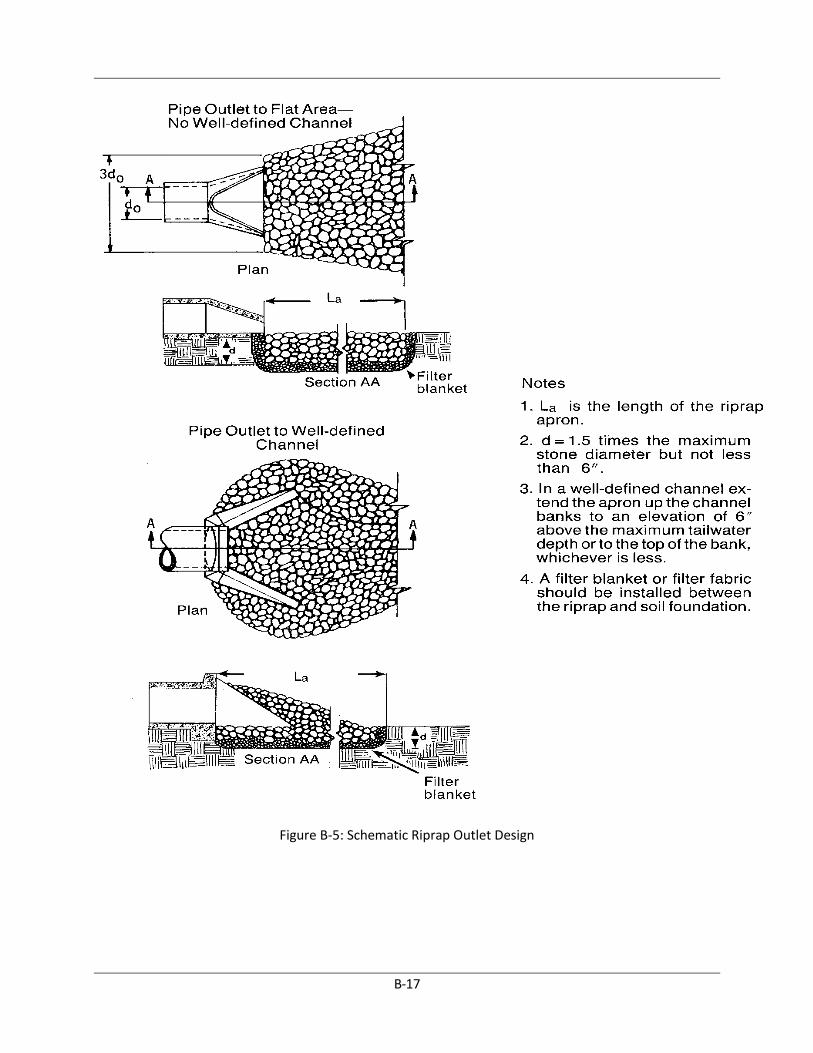
Ensure that the subgrade for the fabric and riprap follows the required lines and grades
shown in the plan. Compact any fill required in the subgrade to the density of the
surrounding undisturbed material. Low areas in the subgrade on undisturbed soil may also
be filled by increasing the riprap thickness (see Figure B-5).
The riprap and fabric must conform to the specified grading limits shown on the plans.
Filter cloth must be properly protected from punching or tearing during installation. Repair
any damage by removing the riprap and placing another piece of filter cloth over the
damaged area. All connecting joints should overlap a minimum of 1 foot. If the damage is
extensive, replace the entire filter cloth.
Riprap may be placed by equipment, but take care to avoid damaging the fabric.
The minimum thickness of the riprap should be 1.5 times the maximum stone diameter.
Riprap may be field stone or rough quarry stone. It should be hard, angular, highly weather-
resistant, and well graded.
Construct the apron on zero grade with no overfall at the end. Make the top of the riprap at
the downstream end level with the receiving area or slightly below it.
Ensure that the apron is properly aligned with the receiving stream and preferably straight
throughout its length. If a curve is needed to fit site conditions, place it in the upstream half
of the apron.
Immediately after construction, stabilize all disturbed areas with vegetation.
Inspection and Maintenance Guidelines
Inspect riprap outlet structures after heavy rains to see if any erosion around or below the riprap
has taken place or if stones have been dislodged. Immediately make all needed repairs to prevent
further damage.
B1.2.6 Level Spreaders
A level spreader is used to convert concentrated runoff into sheet flow and release it uniformly onto
areas stabilized by existing vegetation. Sheet flow conditions are recommended prior to runoff
entering a vegetative filter strip or a creek buffer. During the construction process, level spreaders
can be used where there is a need to divert stormwater away from disturbed areas to avoid
overstressing erosion control measures or where storm runoff can be released in sheet flow down a
stabilized slope without causing erosion.
This section presents a flow spreader consisting of an excavated depression constructed at zero
grade across a slope with a level lip. Multiple options are provided for the level lip and include a
grass hedge row, reinforced vegetation, a rock berm, and a rigid timber lip. Refer to Figures B-6 and

B-16
B-7 for a schematic and cross sections of these various options. Other flow spreader designs can be
used as long as they convert concentrated runoff to sheet flow as defined in this section.
Sheet flow is defined at a flow depth of less than 0.2 foot or 2.4 inches and a velocity of less than
1 foot per second during the peak flow rate from the 1-year, 3-hour storm event under fully
developed conditions. The hydrologic and hydraulic reference tables in sections 2 and 6 of this
Manual, respectively, can be used with the Rational Method to determine the fully developed peak
flow rate. The following equation based on the Continuity Equation (Q = VA) can be used to
determine the required flow spreader length.
Equation C.2 L = 5Q1Year-Dev
where: L = minimum required length of flow spreader (ft)
Q1YR = fully-developed peak flow rate for the 1-year, 3-hour storm event (cubic feet
per second [cfs])
Particular care should be taken to construct the outlet lip at a level elevation in a stable,
undisturbed soil. Any depression in the lip will concentrate the flow, potentially resulting in
erosion. Under higher design flow conditions, a rigid outlet lip design should be used to create the
desired sheet flow conditions. Runoff water containing high sediment loads shall be treated in a
sediment-trapping device before being released to a level spreader.
Installation
Level spreaders should be constructed on undisturbed soil (not fill material).
The entrance to the spreader should be shaped in such a manner as to insure that runoff
enters directly onto the zero grade channel.
Construct a transition section from the diversion channel to blend smoothly to the width
and depth of the spreader.
The level lip should be constructed at zero grade to insure uniform spreading of stormwater
runoff.
Immediately after its construction, establish vegetation along the entire disturbed area of
the spreader. A vegetative cover density of 70% with no large bare areas is required.
Level spreaders are to be staked along a contour prior to construction.
B-17
Figure B-5: Schematic Riprap Outlet Design

B-18
Figure B-6: Level Spreader Schematic and Perspective

B-19
Figure B-7: Level Spreader Lip Options

B-20
Inspection and Maintenance Guidelines
Level spreaders used temporarily or permanently established during construction activities
shall be inspected at least once every 14 calendar days and within 24 hours of the end of a
storm event of 0.5 inch or greater. Level spreaders shall be inspected annually and repairs
made, if required.
Level spreader lip should remain at zero slope to allow proper function of measure.
The contractor should avoid the placement of any material on and prevent construction
traffic across the structure. If the measure is damaged by construction traffic, it should be
repaired immediately.
B1.2.7 Subsurface Drains
A subsurface drain is a perforated conduit such as pipe, tubing, or tile installed beneath the ground
to intercept and convey groundwater. The main purposes are to prevent sloping soils from
becoming excessively wet and subject to sloughing, improve the quality of the growth medium in
excessively wet areas by lowering the water table (Figure B-8), or drain stormwater detention
areas or structures.
Figure B-8: Effect of Subsurface Drain
This measure is appropriate wherever excess water must be removed from the soil. The soil must
be deep and permeable enough to allow an effective system to be installed. Either a gravity outlet
must be available or pumping must be provided. These standards do not apply to foundation drains.
Subsurface drainage systems are of two types: relief drains and interceptor drains. Relief drains are
used either to lower the water table in order to improve the growth of vegetation, or to remove
surface water. They are installed along a slope and drain in the direction of the slope. They can be
installed in a gridiron pattern, a herringbone pattern, or a random pattern (Figure B-9).

B-21
Figure B-9: Subsurface Drainage Patterns
Interceptor drains are used to remove water as it seeps down a slope to prevent the soil from
becoming saturated and subject to slippage. They are installed across a slope and drain to the side
of the slope. They usually consist of a single pipe or series of single pipes instead of a patterned
layout.
Materials
Acceptable materials for subsurface drains include perforated, continuous closed-joint conduits of
PVC, corrugated plastic, concrete, and corrugated metal. The strength and durability of the pipe
should meet the requirements of the site in accordance with the manufacturer’s specifications.
General Installation Requirements
The trench should be constructed on a continuous grade with no reverse grades or low
spots.
Soft or yielding soils under the drain should be stabilized with gravel or other suitable
material.

B-22
Deformed, warped, or otherwise unsuitable pipe should not be used. The minimum
diameter for a subsurface drain should be 4 inches.
Aggregate envelopes (1- to 1½-inch crushed stone) and filter material should be placed as
specified with at least 6 inches of material on all sides of the pipe.
The trench should be backfilled immediately after placement of the pipe. No sections of pipe
should remain uncovered overnight or during a rainstorm. Backfill material should be
placed in the trench in such a manner that the drain pipe is not displaced or damaged.
Relief Drain Installation
Relief drains should be located through the center of wet areas. They should drain in the
same direction as the slope.
Relief drains installed in a uniform pattern should remove a minimum of 1 inch of
groundwater in 24 hours (0.042 cfs/acre). Relief drains installed in a random pattern
should remove a minimum of 1.5 cfs/1,000 feet of length. The design capacity should be
increased accordingly to accommodate any surface water which enters directly into the
system (Figure B-10).
Relief drains installed in a uniform pattern should have equal spacing between drains and
the drains should be at the same depth. Maximum depth is limited by the allowable load on
the pipe, depth to impermeable layers in the soil, and outlet requirements. The minimum
depth is 24 inches under normal conditions. Twelve inches is acceptable where the drain
will not be subject to equipment loading. Spacing between drains is dependent on soil
permeability and the depth of the drain. In general, however, a depth of 3 feet and a spacing
of 50 feet will be adequate.
The minimum velocity required to prevent silting is 1.4 ft/sec. The line should be graded to
achieve at least this velocity. However, steep grades should be avoided.
Envelopes of 1- to 1½-inch crushed stone should be used around all drains for proper
bedding and improved flow of groundwater into the drain. The envelope should consist of 6
inches of aggregate placed completely around the drain. The stone should be encompassed
by a filter cloth separator to prevent the migration of surrounding soil particles into the
drain (Figure B-11). Filter cloth must be designed specifically for soil filtration.
The outlet of the subsurface drain should empty into a channel or some other watercourse
that will remove the water from the outlet. It should be above the normal water level in the
receiving channel. It should be protected from erosion, undermining, damage from periods
of submergence, and the entry of small animals into the drain.
Interceptor Drain Installation
Interceptor drains should remove a minimum of 1.5 cfs/1,000 feet of length. This value
should be increased for sloping land. In addition, if a flowing spring or surface water enters
directly into the system, this flow must be accommodated and the design capacity should be
increased accordingly to take care of this flow.

B-23
Figure B-10: Surface Inlets for Subsurface Drains Schematic
Figure B-11: Subsurface Drain Envelope Schematic

B-24
The depth of installation of an interceptor drain is influenced mainly by the depth to which
the water table is to be lowered. The maximum depth is limited by the allowable load on the
pipe and the depth to an impermeable layer. The minimum depth should be the same as for
relief drains.
One interceptor drain is usually sufficient; however, if multiple drains are to be used,
determining the required spacing can be difficult. The best approach is to install the first
drain—then if seepage or high water table problems occur down slope, install an additional
drain a suitable distance down slope.
Inspection and Maintenance Guidelines
Subsurface drains should be checked periodically and after rainfall events to ensure that
they are free flowing and not clogged with sediment.
The outlet should be kept clean and free of debris.
Surface inlets should be checked weekly, prior to forecasted rain events, after rainfall
events, and kept open and free of sediment and other debris.
Trees located too close to a subsurface drain often clog the system with their roots. If a
drain becomes clogged, relocate the drain.
Where heavy vehicles cross drains, the line should be checked to ensure that it is not
crushed.
B1.2.8 Vegetation
Vegetation is used as a temporary or permanent stabilization technique for disturbed areas. As a
temporary control, vegetation can be used to stabilize stockpiles and barren areas that are inactive
for long periods of time.
Vegetative techniques will apply to every construction project with few exceptions. Vegetation
effectively reduces erosion in swales, stockpiles, berms, mild to medium slopes, and along
roadways.
Supplementary techniques may be required to assist in the establishment of vegetation. These
techniques include erosion control matting, mulches, surface roughening, swales, and dikes to
direct runoff around newly seeded areas, and proper grading to limit runoff velocities during
construction (North Central Texas Council of Governments [NCTCOG], 1993b).
Native versus Introduced Grasses
Introduced grasses, such as bermudagrass and K. R. bluestem, are frequently planted for
erosion control purposes. They may provide superior soil protection, but they may also
have disadvantages, particularly in areas where native grasses are the eventual goal.
Bermudagrass, for example is an excellent soil binder but it provides poor habitat for
ground feeding birds (Anon, 1971). In infertile areas, it can only be maintained with annual

B-25
additions of nitrogen (Bieber et al., 1968). In areas where it is well established, it forms a
uniform dense turf that retards the invasion of desirable native species and provides very
low habitat and species diversity.
Bermudagrass or another introduced species is appropriate where the primary objective is
erosion control. Alternatively, if there are other objectives (e.g., ecological, aesthetic, or
practical goals), native grasses are probably more appropriate. Because the goal of
restoration efforts as discussed here is the establishment of natural vegetation, there seems
to be no reason to plant introduced grasses. The only exception to this is when they are to
be used as temporary ground cover in graded areas where ground work is incomplete and
where they will be graded or plowed under later. If native grasses fail to become established
in an area where it is possible for an introduced species to grow, the latter should of course
be planted. But as a rule, introduced species shall be avoided.
Materials
The type of vegetation used on a site is a function of the season and the availability of water for
irrigation. For areas that are not irrigated, the year can be divided into two temporary planting
seasons and one season for planting of permanent warm weather groundcovers. (See TxDOT
Standard Specification 164 – Seeding for Erosion Control for seeding temporary and permanent
areas for erosion control within the Waco District.)
Bermudagrass has been traditionally specified for permanent vegetation, with the addition of cereal
or winter rye when seeding during cold months to provide temporary cover until the onset of the
growing season for bermudagrass. TxDOT has had success with native grasses and wildflowers, and
recent testing indicates that native species are more drought tolerant and equally effective in terms
of erosion control. A native seed mixture containing Texas wintergrass can be used throughout the
year. Reuse of native topsoil stripped off and stockpiled during site clearing and grubbing provides
an effective means to reestablish native vegetation as the topsoil will contain seed and root
material. Bell and Coryell counties agricultural extension agents are a good source for suggestions
for other types of vegetation. All seed shall be high quality, U.S. Department of Agriculture-certified
seed.
Installation
Interim or final grading must be completed prior to seeding, minimizing all steep slopes. In
addition, all necessary erosion structures such as dikes, swales, diversions, shall also be
installed.
Seedbed shall be well pulverized, loose, and uniform.
A soil analysis is recommended to determine the amount of fertilization required. When
seeding with nonnative species, fertilizer may be applied at the rate of 40 pounds of
nitrogen and 40 pounds of phosphorus per acre, which is equivalent to about 1.0 pounds of
nitrogen and phosphorus per 1,000 square feet. Compost can be used instead of fertilizer
and applied at the same time as the seed.

B-26
Seeding rates should be as specified in TxDOT Standard Specification 164 – Seeding for
Erosion Control or as recommended by a Bell or Coryell County agricultural extension
agent.
The seed shall be applied uniformly with a cyclone seeder, drill, cultipacker seeder, or
hydroseeder (slurry includes seed, fertilizer, and binder). Seed may also be combined with
hydraulic mulch (see Section B.2.11) and applied simultaneously.
Protect the seedbed with a mulch layer to conserve soil moisture. Compost, hay, or straw
are recommended. Hay or straw mulch shall be applied at a rate of approximately 2 tons per
acre. Organic Compost mulch application is covered in Section B.2.10. Hay or straw mulch
shall be anchored by crimping or application of an organic tackifier.
Protect slopes that are steeper than 3H:1V and not exceeding 2H:1V with appropriate
erosion blankets/matting as described in the Section B.2.9 to prevent loss of soil and seed.
Evaluate velocity and shear stress for drainage channels, diversion dikes, and swales and
protect with erosion blankets/matting as described in section B.2.9.
Irrigation Guidance
Temporary irrigation shall be provided according to the schedule described below. Significant
rainfall (on-site rainfall of ½ inch or greater) may allow watering to be postponed until the next
scheduled irrigation. All automatic irrigation systems shall have a dual sensor rain shut off switch
that automatically shuts off the irrigation systems when rain begins to fall and turns on the system
if less than ½ inch of rain occurs.
Time Period Irrigation Amount and Frequency
Within 2 hours of installation Irrigate entire root depth, or to germinate seed
During the next 10 business days Irrigate entire root depth every Monday, Wednesday, and Friday
During the next 30 business days or until Substantial Completion
Irrigate entire root depth a minimum of once per week, or as necessary to ensure vigorous growth
During the next 4 months or until Final acceptance of the Project
Irrigate entire root depth once every 2 weeks, or as necessary to ensure vigorous growth
If cool weather induces plant dormancy, water only as necessary to maintain plant health. Irrigate
in a manner that will not erode the topsoil but will sufficiently soak the entire depth of roots.
Inspection and Maintenance Guidelines
Areas with newly applied vegetation shall be inspected at least once every 14 calendar days
and within 24 hours of the end of a storm event of 0.5 inch or greater to locate and repair
any erosion or other damage.
Erosion from storms or other damage shall be repaired as soon as practical by regrading the
area and applying new seed and mulch.

B-27
If the vegetated cover is less than 70%, the area shall be reseeded.
B1.2.9 Mulch
Mulch can be used as an aid to control erosion on critical sites during land clearing and periods of
construction when revegetation is not practical. The best results are obtained from double
shredded (2 to 4 inch) mulch. The most common uses are as berms at the bottom of long, steep
slopes and as a blanket in channels where designed flow does not exceed 3.5 ft/s; on interceptor
swales and diversion dikes when design flow exceeds 6 ft/s; and on long slopes where rill erosion
hazard is high and planting is likely to be slow to establish adequate protective cover.
Materials
Mulch is easily obtained as a by-product of land clearing operations. It can also be a cost saving item
because it is a recycled material and may be suitable for incorporating into the final vegetation/
landscape.
Inspection and Maintenance Guidelines
Mulch shall be inspected at least once every 14 calendar days and within 24 hours of the
end of a storm event of 0.5 inch or greater to locate and repair any erosion.
Erosion from storms or other damage shall be repaired as soon as practical by applying new
layers of mulch.
B1.2.10 Blankets and Matting
Blankets and matting material can be used as an aid to control erosion in high velocity areas during
the establishment period of protective vegetation. The most common uses are in channels,
interceptor swales, and diversion dikes where designed flow exceeds 6 ft/s, or where shear stresses
exceed erosion resistance of the channel surface; on short, steep slopes where erosion hazard is
high, where planting is likely to be slow to establish adequate protective cover; and on stream
banks where moving water is likely to wash out new vegetative plantings. Shear stresses are used
in selection of the appropriate channel protection. Table B-2 shall be consulted in addition to the
referenced velocity limits to determine the appropriate level of armoring for a channel, swale, or
dike.
Blankets and matting can also be used to create erosion stops on steep, highly erodible soils.
Erosion stops shall be placed approximately 3 feet down channel from point of entry of a
concentrated flow such as from culverts, tributary channels, or diversions or at points where a
change in gradient or course of channel occurs. Spacing of erosion stops on long slopes will vary,
depending on the erodibility of the soil and velocity and volume of flow.

B-28
Biodegradable rolled erosion control products (RECPs) are typically composed of jute fibers, curled
wood fibers, straw, coconut fiber, or a combination of these materials. In order for an RECP to be
considered 100% biodegradable, the netting, sewing or adhesive system that holds the
biodegradable mulch fibers together must also be biodegradable.
Nonbiodegradable RECPs are typically composed of polypropylene, polyethylene, nylon, or other
synthetic fibers. In some cases, a combination of biodegradable and synthetic fibers is used to
construct the RECP. Netting used to hold these fibers together is typically nonbiodegradable as well.
Materials
New types of blankets and matting materials are continuously being developed. TxDOT has defined
the critical performance factors for these types of products, and has established minimum
performance standards that must be met for any product seeking to be approved for use within any
of TxDOT’s construction or maintenance activities. The products that have been approved by
TxDOT are also appropriate for general construction site stabilization within the City of Killeen or
its ETJ. TxDOT maintains a web site at:
http://www.dot.state.tx.us/business/doing_business/product_evaluation/default.htm, which is
continually updated as new products are evaluated.
Installation
Proper installation of blankets and matting is necessary for these materials to function as intended.
They shall always be installed in accordance with the manufacturer’s recommendations. Proper
anchoring of the material and preparation of the soil are two of the most important aspects of
installation. Typical anchoring methods are shown on figures B-12 and B-13.
Soil Preparation and Matting Placement
After site has been shaped and graded to approved design, prepare a friable seed bed
relatively free from clods and rocks more than 1.5 inches in diameter and any foreign
material that will prevent contact of the protective mat with the soil surface.
Fertilize and seed in accordance with seeding or other type of planting plan.
The protective matting can be laid over sprigged areas where small grass plants have been
planted. Where ground covers are to be planted, lay the protective matting first and then
plant through matting according to design of planting.
Install blankets and matting according to manufacturer’s recommendations considering
proper overlapping, direct of flow, and trenching.

B-29
Figure B-12: Typical Initial Anchor Trench for Blankets and Mats
Figure B-13: Typical Terminal Anchor Trench for Blankets and Mats

B-30
Erosion Stops
Erosion stops shall extend beyond the channel lining to the full design cross-section of the
channel to check any rills that might form outside the channel lining.
The trench may be dug with a spade or a mechanical trencher, making sure that the down
slope face of the trench is flat; it shall be uniform and perpendicular to line of flow to permit
proper placement and stapling of the matting.
The erosion stop shall be deep enough to penetrate solid material or below level of ruling in
sandy soils. In general, erosion stops will vary from 6 to 12 inches in depth.
The erosion stop mat shall be wide enough to allow a minimum of 2-inch turnover at
bottom of trench for stapling, while maintaining the top edge flush with channel surface.
Tamp backfill firmly and to a uniform gradient of channel.
Final Check
Make sure:
All matting is uniformly in contact with the soil.
All lap joints are secure.
All staples are flush with the ground.
All disturbed areas seeded.
Inspection and Maintenance Guidelines
Blankets and matting shall be inspected at least once every 14 calendar days and within 24
hours of the end of a storm event of 0.5 inch or greater to locate and repair any damage.
Apply new material if necessary to restore function.
B1.2.11 Organic Compost Mulch
Organic compost mulch consists of applying a mixture of shredded wood fiber, compost, and a seed
mixture with blowing equipment, which temporarily protects exposed soil from erosion by
raindrop impact or wind. Organic compost mulch is suitable for soil disturbed areas requiring
temporary protection until permanent stabilization is established, and disturbed areas that will be
redisturbed following an extended period of inactivity. It is not appropriate for use in creeks or
waterways, but can be used on steep slopes not exceeding 2H:1V. Compost products specified for
use in this application are described in Table B-3. The product’s parameters will vary based on
whether vegetation will be established on the treated slope.
Only compost products that meet all applicable state and federal regulations pertaining to its
production and distribution may be used in this application. Approved compost products must

B-31
meet related state and federal chemical contaminant (e.g., heavy metals, pesticides, etc.) and
pathogen limit standards pertaining to the feedstocks (source materials) in which it is derived.

B-32
Table B-3 Compost Blanket Parameters
Parameters1,4
Reported as (units of measure) Surface Mulch to be Vegetated
Surface Mulch to be left Unvegetated
pH2 pH units 5.0–8.5 N/A
Soluble Salt Concentration
2
(electrical conductivity)
dS/m (mmhos/cm) Maximum 5 Maximum 5
Moisture Content %, wet weight basis 30–60 30–60
Organic Matter Content
%, dry weight basis 25–65 25–100
Particle Size % passing a selected mesh size, dry weight basis
3 inches (75 mm), 100% passing 1 inch (25 mm), 90% to 100% passing ¾ inch (19 mm), 65% to 100% passing ¼ inch (6.4 mm), 0% to 75% passing Maximum particle length of 6 inch (152 mm)
3 inches (75 mm), 100% passing 1 inch (25 mm), 90% to 100% passing ¾ inch (19 mm), 65% to 100% passing ¼ inch (6.4 mm), 0% to 75% passing Maximum particle length of 6 inches (152 mm)
Stability3
Carbon Dioxide Evolution Rate
mg CO2-C per g OM per day
<8 N/A
Physical Contaminants (man-made inerts)
%, dry weight basis <1 <1
1 Recommended test methodologies are provided in Test Methods for the Examination of Composting and Compost (TMECC,
The U.S. Composting Council). 2Each specific plant species requires a specific pH range. Each plant also has a salinity tolerance rating, and maximum tolerable
quantities are known. When specifying the establishment of any plant or turf species, it is important to understand their pH and soluble salt requirements, and how they relate to the compost in use. 3
Stability/Maturity rating is an area of compost science that is still evolving, and as such, other various test methods could be considered. Also, never base compost quality conclusions on the result of a single stability/maturity test. 4 Landscape architects and project (field) engineers may modify the allowable compost specification ranges based on specific
field conditions and plant requirements.

B-33
Materials
Very coarse compost shall be avoided if the slope is to be landscaped or seeded as it will
make planting and crop establishment more difficult.
In regions subject to higher rates of precipitation and/or rainfall intensity, higher compost
application rates should be used. In these particular regions, as well as regions subject to
wind erosion, coarser compost products are preferred.
Notes: Specifying the use of compost products that are certified by the U.S. Composting Council’s
Seal of Testing (STA) Program (www.compostingcouncil.org) will allow for the acquisition of
products that are analyzed on a routine basis, using the specified test methods. STA participants are
also required to provide a standard product label to all customers, allowing easy comparison to
other products.
Installation
The following steps shall be taken for the proper installation of compost as a soil blanket for
erosion/sediment control on sloped areas.
Slightly roughen (scarify) slopes and remove large clods, rocks, stumps, roots larger than
2 inches in diameter and debris on slopes where vegetation is to be established. This soil
preparation step may be eliminated where seeding or planting is not planned. Where
practical, track (compact) perpendicular to contours on the slope using a bulldozer before
applying compost as soil blanket.
Apply compost at the rates specified in Table B-4.
Table B-4 Compost Blanket Application Rates
Annual Rainfall/Flow Rate
Total Precipitation & Rainfall Erosivity Index
Application Rate for Vegetated* Compost
Surface Mulch
Application Rate For Unvegetated Compost
Surface Mulch
Low 1–25 inches, 20–90
½–¾ inch (12.5–19 mm)
1–1½ inch (25–37.5 mm)
Average 26–50 inches, 91–200
¾–1 inch (19–25 mm)
1½–2 inch (37–50 mm)
High 51 inches and above, 201 and above
1–2 inch (25–50 mm)
2–4 inches (50–100 mm)
*These lower application rates should only be used in conjunction with seeding, and for compost blankets applied during the prescribed planting season for the particular region.
Compost blanket application rates should be modified based on specific site (e.g., soil
characteristics, existing vegetation, climate) conditions, as well as particular project related
requirements. The slope grade, and length will also influence compost application rates.

B-34
Based upon increased precipitation and/or rainfall intensity, higher compost application may be
required. On sites possessing severe grades or long slope lengths, the compost blanket may be used
in conjunction with a compost filter berm. The filter berm may be 1 to 2 feet high, by 2 to 4 feet
wide, and may be placed at the top or base (or both) of the slope. Coarser compost products are
preferred if wind erosion or high intensity rainfall are anticipated.
Compost shall be uniformly applied using a pneumatic (blower) unit, or other unit that propels the
product directly at the soil surface, thereby preventing water from moving between the soil-
compost interface. Watering may be used to improve settling of the compost. Apply compost layer
approximately 3 feet over the top of the slope, or overlap it into existing vegetation.
On highly unstable soils, use compost in conjunction with appropriate structural measures.
Dry or hydraulic seeding may be completed following compost application, as required, or during
the compost application itself, where a pneumatic unit is used to apply the compost.
Inspection and Maintenance Guidelines
Mulched areas shall be inspected at least once every 14 calendar days and within 24 hours
of the end of a storm event of 0.5 inch or greater to locate and repair any damage.
B1.2.12 Hydraulic Mulch
Hydraulic mulch consists of applying a mixture of shredded wood fiber or a hydraulic matrix, and a
stabilizing emulsion or tackifier with hydro-mulching equipment, which temporarily protects
exposed soil from erosion by raindrop impact or wind. Hydraulic mulch is suitable for soil
disturbed areas requiring temporary protection until permanent stabilization is established, and
disturbed areas that will be redisturbed following an extended period of inactivity. Seed may be
added to the mulch for temporary or permanent vegetation. It is not appropriate for slopes steeper
than 3H:1V or for use in channels.
Wood fiber hydraulic mulches are generally short lived and need 24 hours to dry before rainfall
occurs to be effective. A second application may be necessary in order to remain effective for an
entire rainy season.
Materials
Hydraulic Mulches – Wood fiber mulch can be applied alone or as a component of hydraulic
matrices. Wood fiber applied alone is typically applied at the rate of 2,000 to 4,000 lb/acre.
Wood fiber mulch is manufactured from wood or wood waste from lumber mills or from
urban sources.
Hydraulic Matrices – Hydraulic matrices include a mixture of wood fiber and acrylic
polymer or other tackifier as binder. Apply as a liquid slurry using a hydraulic application

B-35
machine (i.e., hydro seeder) at the following minimum rates, or as specified by the
manufacturer to achieve complete coverage of the target area: 2,000 to 4,000 lb/acre wood
fiber mulch, and 5 to 10% (by weight) of tackifier (acrylic copolymer, guar, psyllium, etc.)
Bonded Fiber Matrix – Bonded fiber matrix (BFM) is a hydraulically applied system of fibers
and adhesives that upon drying forms an erosion resistant blanket that promotes
vegetation, and prevents soil erosion. BFMs are typically applied at rates from 3,000 lb/acre
to 4,000 lb/acre based on the manufacturer’s recommendation. A biodegradable BFM is
composed of materials that are 100% biodegradable. The binder in the BFM shall also be
biodegradable and shall not dissolve or disperse upon rewetting. Typically, biodegradable
BFMs should not be applied immediately before, during, or immediately after rainfall if the
soil is saturated. Depending on the product, BFMs typically require 12 to 24 hours to dry to
become effective.
Installation
Before application, roughen embankment and fill areas by rolling with a crimping or
punching type roller or by track walking. Track walking shall only be used where other
methods are impractical.
To be effective, hydraulic matrices require 24 hours to dry before rainfall occurs.
Avoid mulch over spray onto roads, sidewalks, drainage channels, existing vegetation, etc.
Inspection and Maintenance Guidelines
Mulched areas shall be inspected at least once every 14 calendar days and within 24 hours
of the end of a storm event of 0.5 inch or greater to locate and repair any damage.
Areas damaged by storms or normal construction activities shall be regraded and hydraulic
mulch reapplied as soon as practical.
B1.2.13 Sod
Sod is appropriate for disturbed areas that require immediate vegetative covers, or where sodding
is preferred to other means of grass establishment. Locations particularly suited to stabilization
with sod are swales carrying intermittent flow, areas around drop inlets, and residential or
commercial lawns where quick use or aesthetics are factors.
The advantages of properly installed sod include:
Immediate erosion control
An instant green surface reducing dust or mud
Nearly year-round establishment capability
Less chance of failure than seed
Reduction of invasive growth

B-36
Quick use of the sodded surface
The option of installing a quality-controlled product with predictable results
It is initially more costly to install sod than to seed. However, this cost is justified in places where
sod can perform better than seed in controlling erosion. In swales and low-flow channels
waterways where concentrated flow will occur, properly pegged sod is preferable to seed because
there is no lag time between installation and the time when the channel is protected by vegetation.
Drop inlets, which will be placed in grassed areas, can be kept free of sediment, and the grade
immediately around the inlet can be maintained by framing the inlet with sod strips.
Sod can be laid during times of the year when grass seed may remain dormant, so long as there is
adequate water available for irrigation in the early weeks. Ground preparation and proper
maintenance are as important with sod as with seed. Sod is composed of living plants and those
plants must receive adequate care to provide vegetative stabilization on a disturbed area.
Materials
Sod shall be machine cut at a uniform soil thickness of 1 inch at the time of cutting. This
thickness shall exclude shoot growth and thatch.
Pieces of sod shall be cut to the supplier’s standard width and length, with a maximum
allowable deviation in any dimension of 5%. Torn or uneven pads shall not be acceptable.
Standard size sections of cut sod shall be strong enough to support its own weight and
retain its size and shape when suspended from a firm grasp on one end of the section.
Sod shall be harvested, delivered, and installed within a period of 36 hours.
Site Preparation
Before soil preparation, areas to be sodded shall be brought to final grade in accordance
with the approved plan.
The surface shall be cleared of all trash, debris and of all roots, brush, wire, grade stakes and
other objects that would interfere with planting, fertilizing, or maintenance operations.
Fertilize according to soil tests. Fertilizer needs can be determined by a soil testing
laboratory or regional recommendations can be made by Bell County agricultural extension
agents. Fertilizer shall be worked into the soil to a depth of 3 inches with a disc, springtooth
harrow, or other suitable equipment. On sloping land, the final harrowing or discing
operation should be on the contour.
General Installation
Sod shall not be cut or laid in excessively wet or dry weather. Sod also shall not be laid on
soil surfaces that are frozen.

B-37
During periods of high temperature, the soil should be lightly irrigated immediately before
laying the sod, to cool the soil and reduce root burning and dieback.
The first row of sod should be laid in a straight line with subsequent rows placed parallel to
and butting tightly against each other. Lateral joints should be staggered to promote more
uniform growth and strength. Care should be exercised to ensure that sod is not stretched
or overlapped and that all joints are butted tight to prevent voids, which would cause drying
of the roots.
On slopes sod should be laid with staggered joints and secured by stapling or other
approved methods. On slopes greater than 3:1 or wherever excessive erosion may be a
problem, sod should not be used.
As sodding of clearly defined areas is completed, sod should be rolled or tamped to provide
firm contact between roots and soil.
After rolling, sod should be irrigated to a depth sufficient that the underside of the sod pad
and the soil 4 inches below the sod is thoroughly wet.
Until such time as a good root system becomes developed, in the absence of adequate
rainfall, watering should be performed as often as necessary to maintain moist soil to a
depth of at least 4 inches.
The first mowing should not be attempted until the sod is firmly rooted, usually 2 to 3
weeks. Not more than one third of the grass leaf should be removed at any one cutting.
Installation in Channels
Sod strips in waterways should be laid perpendicular to the direction of flow. Care should
be taken to butt ends of strips tightly.
After rolling or tamping, sod should be pegged or stapled to resist washout during the
establishment period. Mesh or other netting may be pegged over the sod for extra
protection in critical areas.
Inspection and Maintenance Guidelines
Sod should be inspected at least once every 14 calendar days and within 24 hours of the end
of a storm event of 0.5 inch or greater to locate and repair any damage.
Damage from storms or normal construction activities such as tire ruts or disturbance of
swale stabilization should be repaired as soon as practical.
B1.2.14 Dust Control
The purpose of dust control is to prevent blowing and movement of dust from exposed soil surfaces
and reduce on and off-site damage and health hazards. This practice is applicable to areas subject to
dust blowing and movement where on and off-site damage is likely without treatment.

B-38
Construction activities inevitably result in the exposure and disturbance of soil. Fugitive dust is
emitted both during the activities (i.e., excavation demolition, vehicle traffic, human activity) and as
a result of wind erosion over the exposed earth surfaces. Large quantities of dust are typically
generated in “heavy” construction activities, such as road and street construction and subdivision,
commercial or industrial development, which involve disturbance of significant areas of the soil
surface. Research on construction sites has established an average dust emission rate of 1.2 tons/
acre/month for active construction. Earth moving activities comprise the major source of
construction dust emissions, but traffic and general disturbance of the soil also generate significant
dust emissions.
Temporary Control Methods
Vegetative Cover—See Section B.2.8.
Mulches—See Section B.2.10 or B.2.13 – Chemical mulch binders may be used to bind mulch
material. Commercial binders should be used according to manufacturer’s
recommendations.
Commercially available dust suppressors if applied in accordance with the manufacturers’
directions.
Tillage—to roughen surface and bring clods to the surface. This is an emergency measure
that should be used before soil blowing starts. Begin plowing on windward side of site.
Chisel-type plows spaced about 12 inches apart, spring-toothed harrows and similar plows
are examples of equipment that may produce the desired effect.
Irrigation—Site is sprinkled with water until the surface is moist. Repeat as needed.
Irrigation can be particularly effective for controlling dust during trenching operations. A
dedicated water truck placed next to the trencher and using a “pulse” fog pattern applied to
the discharge belt can effectively control dust. This method is more effective than spraying
the ground ahead of the trencher or the trench itself as it is being dug.
Barriers—Solid board fences, snow fences, burlap fences, crate walls, bales of hay, and
similar materials can be used to control air currents and soil blowing. Barriers placed at
right angles to prevailing currents at intervals of about 15 times their height are effective in
controlling soil blowing.
Permanent Control Methods
Permanent Vegetation—trees or large shrubs may afford valuable protection if left in place.
Topsoil—Covering with less erosive soil material.
Stone—Cover surface with crushed stone or coarse gravel.
Inspection and Maintenance Guidelines
When dust is evident during dry weather, re-apply or repair implemented dust control
BMPs and/or revise dust control plan to implement more effective or appropriate BMPs.

B-39
B1.3 SEDIMENT CONTROL BMPS
B1.3.1 General Guidelines
Construction activities normally result in disturbed/exposed soil areas due to grading operations,
clearing, and other activities. Erosion will occur in the disturbed areas and BMPs should be used to
contain the sediment transported by stormwater runoff. Although many commercial products
suggest that filtration is an important component of sediment removal, almost all reduction in
sediment load is the result of particle settling under relatively quiescent conditions. Consequently,
sediment barriers, such as erosion control logs, silt fences, and rock berms, should be designed and
installed to function as temporary (although leaky) dams.
When viewed as temporary dams, it is easier to see the importance of installing these devices along
a consistent ground contour or with a constant top elevation to prevent concentrating the runoff at
a low spot in the barrier. Concentrating the runoff in this fashion can result in more erosion than
would have occurred if no barrier were installed. Therefore, great care should be taken in the
placement and installation of these types of controls.
For larger areas or where effective installation of sediment barriers is not an option, sediment traps
and sediment basins should be used to control sediment in runoff. These devices are essentially
larger, more permanent dams that temporarily detain stormwater runoff.
All of the sediment control BMPs are potentially very effective for removing sediment from
stormwater runoff when properly maintained and installed. However, observation of many active
construction sites reveals silt fences that are torn or damaged by equipment, evidence of
stormwater bypass, or controls installed in inappropriate locations (i.e., silt fences used in
channels). In these cases, significant resources are expended for little return in the way of water
quality protection. Consequently, proper installation and maintenance should form a key
component of any sediment control plan.
A list of sediment controls and their appropriate siting criteria are contained in Table B-5. More
detailed guidance on siting and maintenance are contained in the subsequent sections. Note that
hay bales are not considered an effective sediment control measure. Compost amended soil can be
used to promote vegetation growth, but it is not considered a sediment control technology.

B-40
Table B-5 Guidelines for Selection of Sediment Control BMPs
Sediment Control Applications Drainage Area Slope Spacing
Construction Entrance/ Exit Should be used at all designated access points NA NA NA
Silt Fence (interior) Areas of minor sheet flow 2 acres < 20% 200 feet
Silt Fence (exterior) Down slope borders of site; up slope border is necessary to divert offsite drainage; for larger areas use diversion swale or berm
NA See Table B-6 See Table B-6
Triangular Filter Dike Alternate to silt fence <1 acre <10% NA
Rock Berm Drainage swales and ditches with and below site <5 acres <30% See Table B-7
High Service Rock Berm Around sensitive features, high flow areas within and below site
<5 acres <30% See Table B-7
Brush Berm Small areas of sheet flow <2 acres <20% See Table B-7
Vegetative Buffer Strips On floodplains, next to wetlands, along stream banks, and on steep slopes
NA NA NA
Inlet Protection Prevent sediment from entering storm drain system <1 acre NA NA
Sediment Trap Used where flows concentrated in a swale or channel 1–5 acres NA NA
Sediment Basin Appropriate for large disturbed areas 5–100 acres NA NA
Erosion Control Logs On slopes to detain sheet flow <1 acre <30% See Table B-7
Dewatering Operations Used to remove groundwater or accumulated storm water from excavations
NA NA NA
Spill Prevention Used on all sites to reduce spills NA NA NA
Creek Crossings Crossings of drainage ways and creeks >5 acres NA NA
Concrete Washout Use on all concrete pouring operations NA NA NA
Table B-6 Silt Fence Spacing on Sloping Sites
Slope Angle
Soil Type (in feet)
Silty Clays Sandy
Very steep (1:1) 50 75 100
Steep (2:1) 75 100 125
Moderate (4:1) 100 125 150
Slight (10:1) 125 150 200
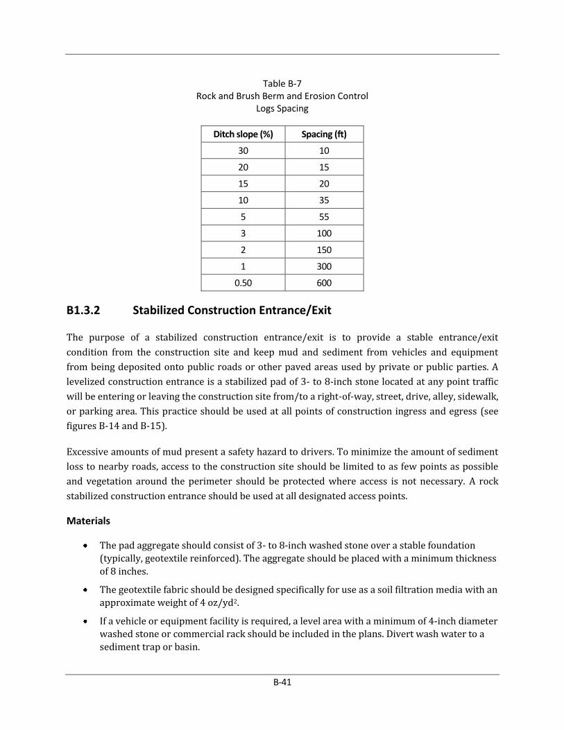
B-41
Table B-7 Rock and Brush Berm and Erosion Control
Logs Spacing
Ditch slope (%) Spacing (ft)
30 10
20 15
15 20
10 35
5 55
3 100
2 150
1 300
0.50 600
B1.3.2 Stabilized Construction Entrance/Exit
The purpose of a stabilized construction entrance/exit is to provide a stable entrance/exit
condition from the construction site and keep mud and sediment from vehicles and equipment
from being deposited onto public roads or other paved areas used by private or public parties. A
levelized construction entrance is a stabilized pad of 3- to 8-inch stone located at any point traffic
will be entering or leaving the construction site from/to a right-of-way, street, drive, alley, sidewalk,
or parking area. This practice should be used at all points of construction ingress and egress (see
figures B-14 and B-15).
Excessive amounts of mud present a safety hazard to drivers. To minimize the amount of sediment
loss to nearby roads, access to the construction site should be limited to as few points as possible
and vegetation around the perimeter should be protected where access is not necessary. A rock
stabilized construction entrance should be used at all designated access points.
Materials
The pad aggregate should consist of 3- to 8-inch washed stone over a stable foundation
(typically, geotextile reinforced). The aggregate should be placed with a minimum thickness
of 8 inches.
The geotextile fabric should be designed specifically for use as a soil filtration media with an
approximate weight of 4 oz/yd2.
If a vehicle or equipment facility is required, a level area with a minimum of 4-inch diameter
washed stone or commercial rack should be included in the plans. Divert wash water to a
sediment trap or basin.

B-42
Figure B-14: Schematic of Temporary Construction Entrance/Exit
Figure B-15: Cross-section of a Construction Entrance/Exit
Installation
Do not place at curves on public roads or on steep slopes. Remove vegetation and other
objectionable material from the foundation area. Grade (crown) foundation for positive
drainage.
The minimum width of the entrance/exit shall not be less than the full width of ingress/
egress or 12 feet, whichever is greater.
The construction site entrance should be at least 50 feet long.
If the slope toward the road exceeds 2%, construct a ridge, 6 to 8 inches high with 3:1 (H:V)
side slopes, across the entrance/exit width approximately 15 feet from the beginning of the
entrance to divert runoff away from the public road.
Place stone to dimensions and grade shown on plans. Create smooth pad surface sloped for
positive drainage.
Divert all surface runoff and drainage from the stone pad to a sediment trap or basin if
necessary.
Install pipe under pad as needed to maintain proper noncontact cross drainage.
B-43
Common Trouble Points
Inadequate runoff control – sediment washes onto public road or other paved area.
Stone too small resulting in muddy condition as stone is pressed into soil.
Pad too short for heavy construction traffic – extend pad beyond the minimum 50-foot
length as necessary.
Pad not flared sufficiently at road intersection, results in mud being tracked on to road and
possible damage to road edge.
Pad not turned or raked after a period of time.
Existing curbs damaged and not properly protected.
Rocks displaced onto roadway and not cleaned up.
Inspection and Maintenance Guidelines
The entrance should be maintained in a condition that will prevent tracking or flowing of
sediment onto public rights-of-way. This may require periodically turning the stones or top
dressing with additional stone as conditions demand and repair and/or cleanout of any
measures used to trap sediment.
All sediment spilled, dropped, washed, or tracked onto rights-of-way or other paved areas
outside of the construction site shall be removed immediately.
When necessary, wheels should be cleaned to remove sediment prior to exiting the
construction site.
When vehicle or equipment washing is required, it should be done on an area stabilized
with crushed stone that drains into an approved sediment trap or sediment basin.
All sediment shall be prevented from entering any storm drain, ditch, or watercourse by
using approved methods.
B1.3.3 Silt Fence
A silt fence is a barrier consisting of geotextile fabric supported by metal posts to prevent soil and
sediment loss from a site. When properly used, silt fences can be highly effective. They help runoff
to pond, allowing heavier solids to settle out. A schematic illustration of a silt fence is shown in
Figure B-16.
The purpose of a silt fence is to intercept and prevent offsite transport of water-borne sediment. Silt
fencing used during construction near the perimeter of a disturbed area to intercept sediment
while allowing water to percolate through. This fence should remain in place until the disturbed
area is permanently stabilized. Silt fence should not be used where there is a concentration of water
in a channel or drainage way. If concentrated flow occurs after installation, corrective action must
be taken such as placing a rock berm in the areas of concentrated flow.

B-44
Figure B-16: Schematic of a Silt Fence Installation
Silt fencing within the site may be temporarily moved during the day to allow construction activity
provided it is replaced and properly anchored to the ground at the end of the day or prior to a rain
event. Silt fences on the perimeter of the site or around drainage ways should not be moved at any
time.
Use J-hooks to trap and pond runoff flowing along uphill side of silt fence as shown on Figure B-17.
This will filter or settle outflows and prevent runoff from escaping around the sides of the fence.
Materials
Silt fence material should be nonwoven fabric, with a minimum unit weight of 4.0 oz/yd2.
Fence posts should be surface painted or galvanized steel, at least 4 feet long with Tee or
Y-bar cross section, surface painted or galvanized.
Woven wire backing to support the fabric should be galvanized 2-x-4-inch welded wire, 12-
gauge minimum.

B-45
Figure B-17: Schematic J-hook Placement
Installation
Steel posts, which support the silt fence, should be installed on a slight angle toward the
anticipated runoff source. Posts must be embedded a minimum of 1 foot deep and spaced
not more than 8 feet on center. Where water concentrates, the maximum spacing should be
6 feet.
Lay out fencing down-slope of disturbed area, following the contour as closely as possible.
Utilize J-hooks as necessary as shown on Figure B-17. The fence should be sited so that the
maximum drainage area is ¼ acre/100 feet of fence.
The toe of the silt fence should be trenched in with a spade or mechanical trencher, so that
the downslope face of the trench is flat and perpendicular to the line of flow. Where fence

B-46
cannot be trenched in (e.g., pavement or rock outcrop), weight fabric flap with 3 inches of
pea gravel on uphill side to prevent flow from seeping under fence.
The trench must be a minimum of 6 inches deep and 6 inches wide to allow for the silt fence
fabric to be laid in the ground and backfilled with compacted material.
Silt fence should be securely fastened to each steel support post, or to woven wire that is in
turn attached to the steel fence post. There should be a 3-foot overlap, securely fastened,
where ends of fabric meet.
Silt fence should be removed when the site is completely stabilized so as not to block or
impede storm flow or drainage.
Common Trouble Points
Fence not installed along the contour causing water to concentrate and flow over the fence
Fabric not seated securely to ground (runoff passing under fence)
Fence not installed perpendicular to flow line (runoff escaping around sides)
Fence treating too large an area or excessive channel flow (runoff overtops or collapses
fence)
Damage to silt fencing not repaired in a timely manner
Inspection and Maintenance Guidelines
Inspect all fencing weekly and within 24 hours after any rainfall in excess of 0.5 inch or
more.
Remove sediment when buildup reaches 6 inches or half the height of the fence, whichever
is less.
Replace any torn fabric.
Replace or repair any sections crushed or collapsed in the course of construction activity. If
a section of fence is obstructing vehicular access, consider relocating it to a spot where it
will provide equal protection, but will not obstruct vehicles. A triangular filter dike may be
preferable to a silt fence at common vehicle access points.
When construction is complete, residual sediment should be disposed of in an approved
spoils area and in a manner that will not cause additional siltation and the location of the
silt fence should be revegetated. The fence itself should be disposed of appropriately.
B1.3.4 Triangular Sediment Filter Dikes
The purpose of a triangular sediment filter dike is to intercept and prevent further transport of
water-borne sediment from unprotected areas. The triangular sediment filter dike is used where
there is no concentration of water upstream of the dike and the contributing drainage area is less
than one acre. If the uphill slope above the dike exceeds 10%, the length of the exposed slope above

B-47
the dike should be less than 50 feet. If concentrated flow occurs after installation, corrective action
should be taken such as placing rock berm in the areas of concentrated flow.
This measure is effective on paved areas where installation of silt fence is not possible or where
vehicle access must be maintained. The advantage of these controls is the ease with which they can
be moved to allow vehicle traffic, then reinstalled to maintain sediment control.
Materials
Silt fence material should be nonwoven fabric. The fabric, with a minimum unit weight of
4.0 oz/yd2.
The dike structure should be 6-gauge 6-x-6-inch wire mesh folded into triangular form.
The sand bag material should be a minimum unit weight 4 oz/yd2, Mullen burst strength
exceeding 300 psi and ultraviolet stability exceeding 70%.
Sandbags should be filled with coarse grade sand, free from deleterious material. The filled
bag should have an approximate weight of 40 pounds and stapled or tied with nylon or poly
cord.
Installation
As shown on Figure B-18, the frame should be constructed of 6-x-6-inch, 6-gauge welded
wire mesh, 18 inches per side, and wrapped with 36 inches of geotextile fabric the same
composition as that used for silt fences.
Filter fabric should lap over ends 6 inches to cover dike to dike junction; each junction
should be secured by shoat rings.
Position dike parallel to the ground contours, with the end of each section closely abutting
the adjacent sections.
There are several options for fastening the filter dike to the ground. The fabric skirt may be
toed-in with 6 inches of compacted material, or 12 inches of the fabric skirt should extend
uphill and be secured with sandbags or a minimum of 3 inches of open graded rock, or with
staples or nails. If these two options are not feasible the dike structure may be trenched-in 4
inches.
Triangular sediment filter dikes should be installed across exposed slopes during
construction with ends of the dike tied into existing grades to prevent failure and should
intercept no more than one acre of runoff.
When moved to allow vehicular access, the dikes should be reinstalled as soon as possible,
but always at the end of the workday or prior to a rain event.

B-48
Figure B-18: Schematic of a Triangular Filter Dike
Common Trouble Points
Fabric skirt missing, too short, or not securely anchored (flows passing under dike)
Gap between adjacent dikes (runoff passing between dikes)
Dike not placed parallel to contour (runoff flowing around dike)

B-49
Inspection and Maintenance Guidelines
Inspection should be made weekly and within 24 hours after each rainfall event in excess of
0.5 inch, and repair or replacement should be made promptly as required to ensure
continued effectiveness.
Inspect and realign dikes as needed to prevent gaps between sections.
Accumulated silt should be removed after it reaches a depth of 6 inches or half the height of
the dike whichever is less, and disposed of in an approved spoils area and in a manner that
will not cause additional siltation.
After the site is completely stabilized, the dikes and any residual silt should be removed. Silt
should be disposed of in a manner that will not contribute to additional siltation.
B1.3.5 Tire Washing Facility
A tire washing facility is used in conjunction with a stabilized construction entrance to provide an
area where truck wheels and undercarriages can be cleaned prior to traversing the stabilized
construction entrance/exit and entering the public road system. A tire wash may consist of an
impervious area or grate over a swale. Wash water is collected and drained to a sediment trapping
device such as a stone outlet sediment trap or sediment basin to provide for removal of sediment
prior to discharge.
Tire washing may be used on large jobs where there is significant truck traffic, on those sites where
site conditions cause the stabilized construction entrance/exit to be overloaded with sediment and
become ineffective and in those instances where contaminated solids might be present on site. They
provide added protection and reduce the need to remove sediment from streets and should be
considered an ancillary component to the stabilized construction entrance/exit (see Figure B-19).
Figure B-19: Schematic Tire Wash Facility

B-50
Installation
The tire washing location should be within the stabilized construction entrance/exit so that
the vehicle does not pick up additional sediment load by traversing disturbed areas.
The size of the tire wash facility should be sufficient so that all wash water and sediment is
collected and drained to a sediment trapping device such as a sediment basin or stone
outlet sediment trap.
A tire wash facility design may consist of many different types of materials or configuration
as long as it provides the intended function. Suggested designs are:
An 8-inch base of crushed rock graded so that wash water drains to a swale; or
Grate suitably designed to support construction vehicles installed over a swale.
The tire wash facility should be designed so that it can be cleaned between uses.
Maintenance
Wheel wash facilities should be inspected at the end of each shift or workday for damage or
repair.
The wheel wash facility should be cleaned between vehicles as necessary.
Sediment that has accumulated in the wash water sedimentation BMP (sediment trap,
sediment basin, etc.) must be removed when it reaches a depth of approximately 1/3 the
design depth of the device or 12 inch, whichever is less.
The removed sediment shall be disposed of in an approved spoils area and not cause
additional siltation. Remove any sediment tracked onto adjacent roadway by sweeping or
scraping as necessary.
Inspection Checklist
Vehicles are leaving the site through designated construction entrance(s)/exit(s).
Mud, dust, or dirt is removed prior to exit onto the adjacent road.
The construction entrance/exit is sufficiently maintained to prevent mud, dirt, fines, and
dust from being tracked off-site.
Stones under wash rack have been maintained and free of deleterious materials.
B1.3.6 Rock Berms
The purpose of a rock berm is to serve as a check dam in areas of concentrated flow, to intercept
sediment-laden runoff, detain the sediment, and release the water in sheet flow. A rock berm is be
used when the contributing drainage area is less than 5 acres. Rock berms are used in areas where
the volume of runoff is too great for a silt fence to contain. They are less effective for sediment
removal than silt fences, particularly for fine particles, but are able to withstand higher flows than a
silt fence. As such, rock berms are often used in areas of channel flows (ditches, gullies, etc.). Rock

B-51
berms are most effective at reducing bed load in channels and should not be substituted for other
erosion and sediment control measures farther upland in the watershed.
Materials
The berm structure should be secured with a woven wire sheathing having maximum
opening of 1 inch and a minimum wire diameter of 20-gauge galvanized and should be
secured with shoat rings.
Clean, open-graded 3- to 5-inch diameter rock should be used, except in areas where high
velocities or large volumes of flow are expected, where 5- to 8-inch diameter rocks may be
used.
Installation
Lay out the woven wire sheathing perpendicular to the flow line. The sheathing should be
20- gauge woven wire mesh with 1-inch openings.
Berm should have a top width of 2 feet minimum with side slopes being 2:1 (H:V) or flatter.
Place the rock along the sheathing as shown in Figure B-20 to a height not less than 18
inches.
Wrap the wire sheathing around the rock and secure with shoat rings so that the ends of the
sheathing overlap at least 2 inches and the berm retains its shape when walked upon.
Berm should be built along the ground contour at 0% grade or as near as possible.
The ends of the berm should be tied into existing upslope grade and the berm should be
buried in a trench approximately 3 to 4 inches deep to prevent failure of the control.
Follow guidelines in Table B-7 regarding rock berm spacing on channels.
Common Trouble Points
Insufficient berm height or length (runoff quickly escapes over the top or around the sides
of berm)
Berm not installed perpendicular to flow line (runoff escaping around one side)
Damage not repaired in a timely manner causing erosion of or a rock berm

B-52
Figure B-20: Schematic Diagram of a Rock Berm
B-53
Inspection and Maintenance Guidelines
Inspection should be made weekly and within 24 hours after each rainfall event in excess of
0.5 inches. For installations in streambeds, additional daily inspections should be made.
Remove sediment and other debris when buildup reaches 6 inches or half the height of the
berm, whichever is less and dispose of in an approved spoils area and in a manner that will
not cause any additional siltation.
Repair any loose wire sheathing.
The berm should be reshaped, as needed.
The berm should be replaced when the structure ceases to function as intended (silt
accumulation among the rocks, washout, construction traffic damage, etc.).
The rock berm should be left in place until all upstream areas are stabilized.
B1.3.7 High Service Rock Berms
A high service rock berm should be designated in areas of important environmental significance
such as above bluffs, permanent springs, pools, recharge features, or other environmentally
sensitive areas that may require a higher level of protection. This type of sediment barrier
combines the characteristics of a silt fence and a rock berm to provide a substantial level of
sediment reduction and a sturdy enough barrier to withstand higher flows. The drainage area to
this device should not exceed 5 acres and the slope should be less than 30%.
Materials
Silt fence material should be nonwoven fabric with a minimum unit weight of 4.0 oz/yd2.
Fence posts should be surface painted or galvanized steel at least 4 feet long with Tee or Y-
bar cross section rebar may also be used to anchor the berm.
Woven wire backing to support the fabric should be galvanized 2-x-4-inch welded wire, 12-
gauge minimum.
The berm structure should be secured with a woven wire sheathing having maximum
opening of 1 inch and a minimum wire diameter of 20-gauge galvanized and should be
secured with shoat rings.
Clean, open-graded 3- to 5-inch diameter rock should be used, except in areas where high
velocities or large volumes of flow are expected, where 5- to 8-inch diameter rocks may be
used.
Installation
Lay out the woven wire sheathing perpendicular to the flow line. The sheathing should be
20-gauge woven wire mesh with 1-inch openings.

B-54
Install the silt fence along the center of the proposed berm placement, as with a normal silt
fence described in Section B.1.5.3.
Place the rock along the sheathing on both sides of the silt fence as shown in the Figure B-
21, to a height not less than 24 inches. Wrap the wire sheathing around the rock and secure
with shoat rings so that the ends of the sheathing overlap at least 2 inches.
The high service rock berm should be removed when the site is revegetated or otherwise
stabilized or it may remain in place as a permanent BMP if drainage is adequate.
Follow guidelines in Table B-7 rock berm spacing on channels.
Figure B-21: Schematic Diagram of High Service Rock Berm
Common Trouble Points
Insufficient berm height or length (runoff quickly escapes over top or around sides of berm)
Berm not installed perpendicular to flow line (runoff escaping around one side)
Internal silt fence not anchored securely to ground (high flows displacing berm)

B-55
When installed in streambeds, they often result in diversion scour, so their use in this
setting is not recommended
Inspection and Maintenance Guidelines
Inspection should be made weekly and within 24 hours after each rainfall event of great
than 0.5 inch. For installations in streambeds, additional daily inspections should be made.
Remove sediment and other debris when buildup reaches 6 inches or half the height of the
berm, whichever is less, and dispose of in an approved spoils area and in a manner that will
not cause additional siltation.
Repair any loose wire sheathing.
The berm should be reshaped, as needed.
The berm should be replaced when the structure ceases to function as intended (silt
accumulation among the rocks, washout, construction traffic damage, etc.).
The rock berm should be left in place until all upstream areas are stabilized.
B1.3.8 Brush Berms
Woody brush material from site clearing can be used effectively for preventing sediment from
leaving the construction site. The key to constructing an efficient brush berm is in the method used
to obtain and place the brush. It is not acceptable to simply take a bulldozer and push whole trees
into a pile. This method does not assure continuous ground contact with the berm and will allow
uncontrolled flows under the berm.
Brush berms may be used where there is little or no concentration of water in a channel or other
drainage way above the berm. The size of the drainage area should be no greater than one-fourth of
an acre per 100 feet of barrier length; the maximum exposed slope length behind the barrier should
not exceed 100 feet; and the maximum slope gradient behind the barrier should be less than 50%
(2:1). Figure B-22 illustrates a brush berm.
Materials
The brush should consist of woody brush and branches less than 2 inches in diameter.
The filter fabric should conform to the specifications for filter fence fabric.
The rope anchors should be 3/8-inch diameter rebar stakes that are 18 inches long.

B-56
Figure B-22: Schematic Diagram of a Brush Berm

B-57
Guidelines for Installation
Lay out the brush berm following the ground contour as closely as possible.
The brush limbs should be cut and hand placed with the vegetated part of the limb in close
contact with the ground. Each subsequent branch should overlap the previous branch
providing a shingle effect.
The brush berm should be constructed with each layer extending the entire length of the
berm before the next layer is started.
Drive the rope anchors into the ground at approximately a 45 degree angle to the ground.
The anchors should be place alternately on 6-foot centers on both sides of the berm so that
there is no more than 6 feet between stakes on any one side of the berm.
Fasten the rope to the anchors and tighten berm securely to the ground.
The height of the brush berm should be a minimum of 24 inches after the securing ropes
have been tightened.
A trench should be excavated 6 inches wide and 4 inches deep along the length of the
barrier and immediately uphill from the barrier.
The filter fabric should be cut into lengths sufficient to lay across the barrier from its up-
slope base to just beyond its peak. The lengths of filter fabric should be draped across the
width of the barrier with the uphill edge placed in the trench and the edges of adjacent
pieces overlapping each other. Where joints are necessary, the fabric should be spliced
together with a minimum 6-inch overlap and securely sealed.
The trench should be backfilled and the soil compacted over the filter fabric.
Set stakes into the ground along the downhill edge of the brush barrier, and anchor the
fabric by tying rope from the fabric to the stakes. Drive the rope anchors into the ground at
approximately a 45-degree angle to the ground on 6-foot centers.
Fasten the rope to the anchors and tighten berm securely to the ground with a minimum
tension of 50 pounds.
The height of the brush berm should be a minimum of 24 inches after the securing ropes
have been tightened.
Follow guidelines in Table B-7 regarding rock and brush berm and erosion control logs
spacing on channels.
Common Trouble Points
Gaps between berm and ground due to uneven ground surface, inadequately compacted
berm, or inadequately secured berm (runoff passing directly under berm).
Berm receiving excessive volumes or velocities of flow (runoff overtopping or displacing
berm).

B-58
Inspection and Maintenance Guidelines
The area upstream from the brush berm should be maintained in a condition that will allow
accumulated silt to be removed following the runoff of a rainfall event.
The berm should be inspected at least once every 14 calendar days and within 24 hours of
the end of a storm event of 0.5 inch or greater.
When the silt reaches a depth of 6 inches or half the height of the berm, whichever is less, it
should be removed and disposed of in an approved spoils area and in a manner that will not
cause additional siltation.
Periodic tightening of the anchoring ropes may be required due to shrinkage of the brush
berm as it deteriorates over time;
Brush berms should be replaced after 3 months or be repaired or reconstructed when loss
of foliage occurs or when they no longer function as intended.
B1.3.9 Check Dams
Check dams are small barriers consisting of rock or earthen berms placed across a drainage swale
or ditch. They reduce the velocity of small concentrated flows, provide a limited barrier for
sediment, and help disperse concentrated flows to reduce potential erosion.
They are used primarily in long drainage swales or ditches in which permanent vegetation may not
be established and erosive velocities are present. They are typically used in conjunction with other
techniques such as, riprap or other sediment reduction techniques. They are useful in reducing flow
then conveyed to other sediment controls.
Although check dams are effective in reducing flow velocity and thereby lowering the potential for
channel erosion, it is usually better to establish a protective vegetative lining before flow is
confined or to install a structural channel lining. However, under circumstances where this is not
feasible, check dams are useful.
Materials
Although many different types of material can be used to create check dams, aggregate and
riprap produce the most stable structure.
If the drainage area is less than 2 acres, coarse aggregate alone can be used for the dam.
For drainage areas between 2 and 10 acres, a combination of coarse aggregate and riprap as
shown on Figure B-23 should be used.
Guidelines for Installation
The dam height should be between 18 and 36 inches.

B-59
Figure B-23: Schematic Diagram of a Rock Check Dam

B-60
The center of the check dam should be at least 6 inches lower than the outer edges to
promote a “weir” effect. Storm water flows are then forced to the stone-soil interface,
thereby promoting scour at that point and subsequent failure of the structure to perform its
intended function.
The dam should be designed so that the 1-year, 3-hour storm or design storm for the water
conveyance, whichever is greater, will pass the dam without causing excessive upstream
flooding.
For added stability, the base of the check dam may be keyed into the soil approximately 6
inches.
The maximum spacing between the dams should be such that the toe of the upstream dam
is at the same elevation as the top of the downstream dam. Follow spacing guidelines in
Table B-7 regarding berm spacing on channels
Stone should be placed according to the configuration on Figure B-24. Hand or mechanical
placement will be necessary to achieve complete coverage of the ditch or swale and to
ensure that the center of the dam is lower than the edges.
Filter cloth may be used under the stone to provide a stable foundation and to facilitate the
removal of the stone.
Figure B-24: Filter Fabric Inlet Protection
Common Trouble Points
Check dams installed in grass-lined channels may kill the vegetative lining if submergence
after rains is too long and/or silting is excessive.
If check dams are used in grass-lined channels that will be mowed, care should be taken to
remove all the stone when the dam is removed. Stones often wash downstream and can
damage mowing equipment and present a safety hazard.
Inspection and Maintenance Guidelines
Check dams should be inspected at least once every 14 calendar days and within 24 hours
of the end of a storm event of 0.5 inch or greater.
Sediment should be removed when it reaches one half of the height of the check dam at any
given point of measurement.

B-61
Regular inspections should be made to ensure that the center of the dam is lower than the
edges. Erosion caused by high flows around the edges of the dam should be repaired
immediately.
B1.3.10 Vegetative Buffers
Buffer zones are undisturbed strips of natural vegetation or established suitable plantings that will
provide a living filter to reduce soil erosion and runoff velocities. Natural buffer zones are used
along streams and other bodies of water that need protection from erosion and sedimentation.
Vegetative buffers may be used to protect swales and ditches and may be incorporated into natural
landscaping of an area. They can provide critical habitat adjacent to streams and wetlands, as well
as assisting in controlling erosion, especially on unstable steep slopes.
The buffer zone may be an area of vegetation that is left undisturbed during construction, or it may
be newly planted. If buffer zones are preserved, existing vegetation, good planning, and site
management are needed to prevent disturbances such as grade changes, excavation, damage from
equipment, and other activities. The creation of new buffer strips requires the establishment of a
good dense turf (at least 80% coverage) and may include trees and shrubs. The slope cannot exceed
12%. The minimum width of a vegetative buffer used for sediment control should be 50 feet.
Guidelines for Installation
Preserving natural vegetation or plantings in clumps, blocks, or strips is generally the
easiest and most successful method.
All unstable steep slopes should be left in natural vegetation.
Fence or flag clearing limits and keep all equipment and construction debris out of the
buffer zone.
Keep all excavations outside the drip-line of trees and shrubs.
Debris or extra soil should not be pushed into the buffer zone.
Inspection and Maintenance Guidelines
Inspection and careful maintenance are important to ensure healthy vegetation. The need for
routine maintenance such as mowing, fertilizing, irrigating, and invasive weed and pest control will
depend on the species of plants and trees, soil types, location and climatic conditions. County
agricultural extension agencies are a good source for this type of information.
B1.3.11 Inlet Protection
Storm sewers put in use before stabilization of the associated capture areas can intercept and
convey large amounts of sediment. In case of extreme sediment loading, the storm sewer itself may

B-62
clog and lose a major portion of its capacity. To avoid these problems, it is necessary to prevent
sediment from entering the system at the inlets.
All underground storm sewers inlets that may receive storm runoff from disturbed areas should be
protected. Temporary inlet protection measures provide protection against silt transport or
accumulation in storm sewer systems. This accumulation can greatly reduce or completely stop the
flow in the pipes. Different measures are used for different site conditions and inlet types.
Care should be taken when choosing a specific type of inlet protection. Inlet protection that causes
excessive ponding in an area of high construction activity may become a nuisance whereby it is
removed or bypassed, thus transmitting sediment-laden flows unchecked. In such situations, a
structure with an adequate overflow mechanism should be utilized.
Inlet protection devices are designed to be installed on construction sites and not on streets and
roads open to the public. When used on public streets, these devices will cause ponding of runoff,
which can cause flooding and can present a traffic hazard. When construction occurs adjacent to
active streets, sediment should be controlled on site and not on public thoroughfares. Occasionally,
roadwork or utility installation will occur on public roads. In these cases, inlet protection is an
appropriate temporary BMP.
The following inlet protection devices are for drainage areas of 1 acre or less. Runoff from larger
disturbed areas should be routed to a temporary sediment trap or basin.
Filter barrier protection using erosion control logs or silt fence is appropriate when the drainage
area is less than 1 acre and the basin slope is less than 5%. This type of protection is not applicable
in paved areas.
Materials
Filter fabric should be a nonwoven fabric with a minimum weight of 4.0 oz/yd2.
Erosion control logs should be composed of material as defined in Section B1.5.14.
Posts for erosion control logs or fabric should be 2-x-4-inch pressure treated wood stakes
or galvanized steel, tubular in cross-section or they may be standard fence “T” posts.
Wire mesh should be standard hardware cloth or comparable wire mesh with an opening
size not to exceed ½ inch.
The sand bag material should be a minimum unit weight 4 oz/yd2, Mullen burst strength
exceeding 300 psi, and ultraviolet stability exceeding 70%.

B-63
Guidelines for Installation
Silt Fence Area Inlet Protection
Silt fence should conform to the specifications listed in Section B1.5.3.
For stakes, use 2-x-4-inch wood or equivalent metal with a minimum length of 3 feet.
Space stakes evenly around the perimeter of the inlet a maximum of 3 feet apart, and
securely drive them into the ground, approximately 12 inches deep.
Place the bottom 12 inches of the fabric in a trench and backfill the trench with 12 inches of
compacted soil.
Fasten fabric securely to the stakes and frame. Joints must be overlapped to the next stake.
It may be necessary to build a temporary dike on the down slope side of the structure to
prevent bypass flow.
If the area inlet is above the finished grade, the drop openings or grate may be completely covered
with filter fabric. The fabric should be securely attached to the entire perimeter of the inlet.
Erosion Control Log Area Inlet Protection
Erosion control logs should conform to the specifications listed in Section B1.5.14.
Space stakes evenly around the perimeter of the inlet a maximum of 3 feet apart and
securely drive them into the ground, approximately 18 inches deep.
Fasten fabric securely to the stakes and frame. Joints must be overlapped to the next stake.
It may be necessary to build a temporary dike on the down slope side of the structure to
prevent bypass flow.
Silt Fence Curb Inlet Protection
Cut a continuous piece of wire mesh to extend from the top of curb over the inlet opening
and along the gutter as shown on Figure B-25.
Attach the filter fabric to the wire mesh and cut away a 4-inch clear section near the top of
curb to act as a weir.
Place the assembly against the curb inlet opening and assure the inlet opening is fully
covered.
Place sand bags or alternate weight to weigh down the assembly at the top of curb and in
the gutter on each side to assure no movement.
This type of protection should be inspected frequently and the filter cloth replaced when
clogged with sediment.
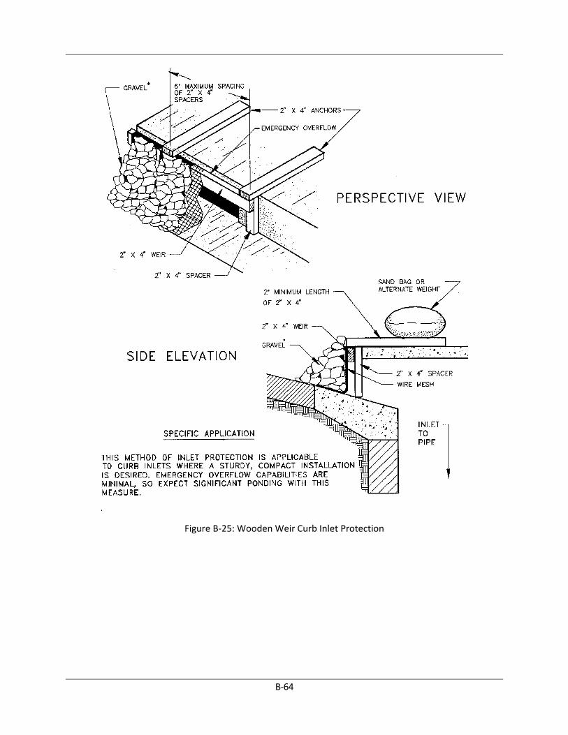
B-64
Figure B-25: Wooden Weir Curb Inlet Protection

B-65
Assure that storm flow does not bypass inlet by installing temporary dikes directing flow
into inlet as necessary.
Erosion Control Log Curb Inlet Protection
Place erosion control log in gutter around inlet opening allowing erosion control log to
extend 12 inches on either side of opening. Assure direct contact with surface of gutter
flowline.
Place sandbags between inlet opening and erosion control log to allow for weir flow.
An erosion control log may be necessary to be placed on the back of curb if site is not
stabilized with vegetation.
This type of protection should be inspected frequently and the erosion control log replaced
when clogged with sediment.
B1.3.12 Stone Outlet Sediment Trap
A stone outlet sediment trap is an impoundment created by the placement of an earthen and stone
embankment to prevent soil and sediment loss from a site. The purpose of a sediment trap is to
intercept sediment-laden runoff and trap the sediment to protect drainage ways, properties, and
rights-of-way below the sediment trap. The sediment trap is installed at each point of discharge
from disturbed areas. The drainage area for a sediment trap is recommended to be less than 5
acres. Larger areas should be treated using a sediment basin. A sediment trap differs from a
sediment basin mainly in the type of discharge structure. A schematic of a sediment trap is shown
on Figure B-26.
The trap should be located to obtain the maximum storage benefit from the terrain, for ease of
cleanout and disposal of the trapped sediment, and to minimize interference with construction
activities. The volume of the trap should be at least 1,800 cubic feet per acre of drainage area.
Materials
Filter stone aggregate should be at least 3 inches in diameter and should not exceed a
volume of 0.5 cubic foot.
The geotextile fabric specification should be woven polypropylene, polyethylene or
polyamide geotextile, minimum unit weight of 4.0 oz/yd2, Mullen burst strength exceeding,
300 psi and ultraviolet stability exceeding 70%.

B-66
Figure B-26: Schematic Diagram of a Sediment Trap

B-67
Installation
Earth Embankment: Place fill material in layers not more than 8 inches in loose depth.
Before compaction, moisten or aerate each layer as necessary to provide the optimum
moisture content of the material. Compact each layer to 90% standard proctor density. Do
not place material on surfaces that are muddy or frozen. Side slopes for the embankment
are to be 3:1. The minimum width of the embankment should be 3 feet.
A gap is to be left in the embankment in the location where the natural confluence of runoff
crosses the embankment line. The gap is to have a width in feet equal to 6 times the
drainage area in acres.
Geotextile Covered Rock Core: A core of filter stone having a minimum height of 1.5 feet
and a minimum width at the base of 3 feet should be placed across the opening of the earth
embankment and should be covered by geotextile fabric which should extend a minimum
distance of 2 feet in either direction from the base of the filter stone core.
Filter Stone Embankment: Filter stone should be placed over the geotextile and should
have a side slope which matches that of the earth embankment of 3:1 and should cover the
geotextile/rock core a minimum of 6 inches when installation is complete. The crest of the
outlet should be at least 1 foot below the top of the embankment.
Common Trouble Points
Flooding upstream of dam impacting construction operations (poor hydraulic efficiency).
Amount of land required limits the application of this measure.
Inspection and Maintenance Guidelines
Inspection should be made weekly and within 24 hours after each rainfall event in excess of
0.5 inch. Check the embankment, spillways, and outlet for erosion damage, and inspect the
embankment for piping and settlement. Repair should be made promptly, as needed.
Trash and other debris should be removed promptly to prevent clogging of the outlet
structure.
Sediment should be removed and the trap restored to its original dimensions when the
sediment has accumulated to half of the design depth of the trap.
Sediment removed from the trap should be deposited in an approved spoils area and in a
manner that will not cause additional siltation.
B1.3.13 Sediment Basins
The purpose of a sediment basin is to intercept sediment-laden runoff and trap the sediment to
protect drainage ways, properties, and rights of way below the sediment basin. A sediment basin is
usually installed at the primary point of discharge from larger disturbed areas. The drainage area
for a sediment basin is typically great that 5 acres but recommended to be less than 100 acres and
located off creeks or channels.

B-68
Sediment basins are effective for capturing and slowly releasing the runoff from larger disturbed
areas thereby allowing sedimentation to take place. A sediment basin can be installed where a
permanent pond BMP will ultimately be constructed. Guidelines for construction of the permanent
BMP should be followed, but revegetation, placement of underdrain piping, and installation of sand
or other filter media should not be carried out until site construction is complete. A schematic of a
sediment basin is shown on Figure B-27.
Materials
The pond outlet should be UV-resistant plastic piping or reinforced concrete piping with
watertight fittings or end to end connections of sections.
The outlet pipe and should have positive flow to a stabilized outlet on the downstream side
of the embankment.
An anti-vortex device and trash rack should be attached to the top of the riser.
Basin Design and Construction
For common drainage locations that serve an area with ten or more acres disturbed at one
time, the sediment basin volume should be 1,800 cubic feet of storage for each disturbed
acre.
The basin length to width ratio should be at least 2:1 to improve trapping efficiency. The
shape may be attained by excavation or the use of baffles. The lengths should be measured
at the elevation of the top of the riser pipe.
Place fill material in layers not more than 8 inches in loose depth. Before compaction,
moisten or aerate each layer as necessary to provide the optimum moisture content of the
material. Compact each layer to 90% standard proctor density. Do not place material on
surfaces that are muddy or frozen. Side slopes for the embankment should be 3:1 (H:V).
An earthen emergency spillway should be installed and sized to carry the full amount of
flow generated by the 100-year design storm event with 1 foot of freeboard less the amount
carried by principal outlet control device at this design head.
The emergency spillway should be lined with riprap, as should the swale leading from the
spillway to the normal watercourse at the base of the embankment.
The principal outlet control device should consist of a rigid vertically oriented pipe or box.
Attached to this structure should be a horizontal pipe, which should extend through the
embankment to the toe of fill to provide a dewatering outlet for the basin.
An anti-vortex device should be attached to the inlet portion of the principal outlet control
device to serve as a rubbish screen.
A concrete base should be used to anchor the principal outlet control device and should be
sized to provide a safety factor of 1.5 (downward forces = 1.5 buoyant forces).

B-69
Figure B-27: Schematic of a Sediment Basin

B-70
The basin should include a permanent stake to indicate the sediment level in the pool and
marked to indicate when the sediment occupies 50% of the basin volume, which should not
be the top of the stake.
The top of the riser should be 12 inches below the elevation of the emergency spillway. The
riser should be sized to convey the runoff from the 1-year storm when the water surface is
at the emergency spillway elevation. For basins with no spillway the riser must be sized to
convey the runoff from the 10-year storm.
Anti-seep collars should be included when soil conditions or length of service make piping
through the backfill a possibility.
A 48-hour drawdown time will be achieved by using a riser pipe perforated at the point
measured from the bottom of the riser pipe equal to ½ the volume of the basin. This is the
maximum sediment storage elevation. The size of the perforation may be calculated as
follows:
Equation 3. Ao = [As * (2h)0.5/[Cd * 980,000]
Where: Ao = Area of the de-watering perforation, ft2
As = Surface area of the basin, ft2
Cd = Coefficient of contraction, approximately 0.6
h = head of water above the perforation, ft
Perforating the riser with multiple holes with a combined surface area equal to Ao is acceptable.
Common Trouble Points
Storm events that exceed the design storm event causing damage to the spillway structure
of the basin or causing adverse impacts downstream.
Flow occurring in the fill material around outlet pipe causing failure of the embankment.
Inspection and Maintenance Guidelines
Inspection should be made weekly and within 24 hours after each rainfall event in excess of
0.5 inch. Check the embankment, spillways, and outlet for erosion damage, and inspect the
embankment for piping and settlement. Repair should be made promptly, as needed.
Trash and other debris should be removed promptly to prevent clogging of the outlet
structure.
Accumulated silt should be removed and the basin should be regraded to its original
dimensions at such point that the capacity of the impoundment has been reduced to 50% of
its original storage capacity.

B-71
The removed sediment should be deposited in an approved spoils areas and in a manner
that will not cause additional siltation.
B1.3.14 Erosion Control Logs
An erosion control log consists of wood excelsior, coconut fibers, mulch, or other similar materials
bound into a tight tubular roll. When erosion control logs are placed at the toe and on the face of
slopes, they intercept runoff, reduce its flow velocity, release the runoff as sheet flow, and provide
removal of sediment from the runoff. By interrupting the length of a slope, erosion control logs can
also reduce erosion.
Erosion control logs may be suitable:
Along the toe, top, face, and at grade breaks of exposed and erodible slopes to shorten slope
length and spread runoff as sheet flow
At the end of a downward slope where it transitions to a steeper slope
Along the perimeter of a project
As check dams in earthen channels or swales
Downslope of exposed soil areas
Around temporary soil or aggregate stockpiles
Materials:
Core material: Core material should be biodegradable or recyclable. Material may be
compost, mulch, aspen wood fibers, chipped site vegetation, agricultural rice or wheat
straw, coconut fiber, 100% recyclable fibers, or similar materials.
Containment Mesh: Containment mesh should be 100% biodegradable, photodegradable,
or recyclable such as burlap, twine, UV photodegradable plastic, polyester, or similar
material. When the erosion control log will remain in place as part of a vegetative system
use biodegradable or photodegradable mesh. For temporary installation recyclable mesh is
recommended.
Basic Design and Construction
Locate erosion control logs on level contours spaced as follows:
Slope inclination of 4:1 (H:V) or flatter: Erosion control logs should be placed at a
maximum interval of 20 feet.
Slope inclination between 4:1 and 2:1 (H:V): Erosion control logs should be placed at a
maximum interval of 15 feet (a closer spacing is more effective).
Slope inclination 2:1 (H:V) or greater: Erosion control logs should be placed at a
maximum interval of 10 feet (a closer spacing is more effective).

B-72
Turn the ends of the erosion control log up slope to prevent runoff from going around the
roll.
Stake erosion control logs into a 2- to 4-inch-deep trench with a width equal to the diameter
of the erosion control log.
Drive stakes at the end of each erosion control log and spaced 4 feet maximum on center.
Use wood stakes with a nominal classification of 2 x 2 inches and minimum length of
24 inches.
If more than one erosion control log is placed in a row, the rolls should be overlapped, not
abutted.
Follow Table B-7 Rock and Brush Berm and Erosion control logs Spacing on Channels.
Limitations:
Difficult to move once saturated.
If not properly staked and trenched in, erosion control logs could be transported by high
flows.
Erosion control logs have a very limited sediment capture zone.
Erosion control logs should not be used on slopes subject to creep, slumping, or landslide.
Inspection and Maintenance Guidelines
Inspect prior to rain event, daily during extended rain events, within 24 hours after rain
events exceeding 0.5 inch, and weekly.
Repair or replace split, torn, unraveling, or slumping erosion control logs.
If the erosion control log is used as a sediment capture device, or as an erosion control
device to maintain sheet flows, sediment that accumulates behind the roll must be
periodically removed to maintain its effectiveness. Sediment should be removed when the
accumulation reaches one-half the designated sediment storage depth, usually one-half the
distance between the top of the erosion control log and the adjacent ground surface.
Sediment removed during maintenance should be deposited in an approved spoils area and
in a manner that will not cause additional siltation.
B1.3.15 Dewatering Operations
Dewatering operations are practices that limit the discharge of pollutants when non-storm water
and accumulated precipitation or groundwater must be removed from a work location so that
construction work may be accomplished.
The controls detailed in this BMP only allow for minimal settling time for sediment particles and
should only be used when site conditions restrict the use of the other control methods. When

B-73
possible, avoid offsite discharges by using the water for dust control, by infiltration, or allowing the
water to evaporate.
A variety of methods can be used to achieve pollutant removal during dewatering operations. When
pumping water out or through a pollutant removal device, a floatation device should be attached to
the pump inlet.
Pressurized filters tend to be more expensive than gravity settling, but are often more effective.
Simple tanks are generally rented on a long-term basis (one or more months).
Inspection and Maintenance
Inspect and verify that activity-based BMPs are in place prior to the commencement of
associated dewatering activities. While activities associated with the BMP are under way,
inspect weekly and after every 0.5 inch rainfall event in excess of 0.5 inch to verify
continued BMP implementation.
Inspect BMPs subject to nonstormwater discharges daily while nonstormwater discharges
occur.
BMP specific maintenance requirements are included with the description of each
technology described in this Section.
Sediment removed during the maintenance of a dewatering device may be either spread
onsite and stabilized, or disposed of in an approved spoils area.
Sediment that is commingled with other pollutants must be disposed of in accordance with
all applicable laws and regulations.
Weir Tanks
Description
A weir tank separates liquids and solids by using weirs. The configuration of the weirs (over and
under weirs) maximizes the residence time in the tank and determines the waste to be removed
from the water, such as oil, grease, and sediments.
Appropriate Applications
The tank removes trash, some settleable solids (gravel, sand, and silt), some visible oil and grease,
and some metals (removed with sediment). To achieve high levels of flow, multiple tanks can be
used in parallel. If additional treatment is desired, the tanks can be placed in series or as
pretreatment for other methods.

B-74
Implementation
Tanks are delivered to the site by the vendor, who can provide assistance with set-up and
operation.
Tank size will depend on flow volume, constituents of concern, and residency period
required. Vendors should be consulted to appropriately size tank.
Maintenance
Periodic cleaning is required based on visual inspection or reduced flow.
Oil and grease disposal must be by licensed waste disposal company.
Dewatering Tanks
Description
A dewatering tank removes debris and sediment. Flow enters the tank through the top, passes
through a fabric filter, and is discharged through the bottom of the tank. The filter separates the
solids from the liquids.
Appropriate Applications
The tank removes trash, gravel, sand, and silt, some visible oil and grease, and some metals
(removed with sediment). To achieve high levels of flow, multiple tanks can be used in parallel. If
additional treatment is desired, the tanks can be placed in series or as pretreatment for other
methods.
Implementation
Tanks are delivered to the site by the vendor, who can provide assistance with set-up and
operation.
Tank size will depend on flow volume, constituents of concern, and residency period
required. Vendors should be consulted to determine appropriate size of tank.
Maintenance
Periodic cleaning is required based on visual inspection or reduced flow.
Oil and grease disposal must be by licensed waste disposal company.

B-75
Gravity Bag Filter
Description
A gravity bag filter, also referred to as a dewatering bag, is a square or rectangular bag made of
nonwoven geotextile fabric that collects sand, silt, and fines.
Appropriate Applications
Effective for the removal of sediments (gravel, sand, and silt). Some metals are removed
with the sediment.
Implementation
Water is pumped into one side of the bag and seeps through the bottom and sides of the
bag.
A secondary barrier, such as a rock filter bed or erosion control logs, is placed beneath and
beyond the edges of the bag to capture sediments that escape the bag.
Maintenance
Inspection of the flow conditions, bag condition, bag capacity, and the secondary barrier is
required.
Replace the bag when it no longer filters sediment or passes water at a reasonable rate. The
bag may typically be disposed of with other trash or rubbish.
B1.3.16 Spill Prevention and Control
This section describes measures to prevent or reduce the discharge of pollutants to drainage
systems or watercourses from leaks and spills. This is accomplished by reducing the chance for
spills, stopping the source of spills, containing and cleaning up spills, properly disposing of spill
materials, and employee training.

B-76
The following steps will help reduce the negative impacts of leaks and spills:
Education
Make sure that each employee knows what a “significant spill” is for each material they use,
and what is the appropriate response for “significant” and “insignificant” spills. Employees
should also be aware of when spills must be reported to the Texas Commission on
Environmental Quality (TCEQ). Information available in 30 TAC 327.4 and 40 CFR 302.4.
Educate employees and subcontractors on potential dangers to humans and the
environment from spills and leaks.
Hold regular meetings to discuss and reinforce appropriate disposal procedures
(incorporate into regular safety meetings).
Establish a continuing education program to educate new employees.
Enforce proper spill prevention and control measures.
General Measures
To the extent that the work can be accomplished safely, spills of oil, petroleum products,
and substances listed under 40 CFR Parts 110, 117, and 302 should be contained and
cleaned up immediately.
Store hazardous materials and wastes in covered containers and protect from vandalism.
Place a stockpile of spill cleanup materials where it will be readily accessible and protected
from drainage.
Train employees in spill prevention and cleanup.
Designate responsible individuals to oversee and enforce control measures.
Provide regular maintenance for comfort stations (i.e., porta-potties).
Spills should be covered and protected from stormwater runoff during rainfall to the extent
that it doesn’t compromise cleanup activities.
Do not wash spills with water.
Store and dispose of used clean up materials, contaminated materials, and recovered spill
material that is no longer suitable for the intended purpose in conformance with the
provisions in applicable BMPs.
Do not allow water used for cleaning and decontamination to enter storm drains or
watercourses. Collect and dispose of contaminated water in accordance with applicable
laws and regulations.
Contain water overflow or spillage and do not allow it to discharge into storm drain or
watercourses.
Place Material Safety Data Sheets (MSDS), as well as proper storage, cleanup, and spill
reporting instructions for hazardous materials stored or used on the construction site in an
open, conspicuous, and accessible location.

B-77
Keep waste storage areas clean, well organized, and equipped with ample cleanup supplies
as appropriate for the materials being stored. Perimeter controls, containment structures,
covers, and liners should be repaired or replaced as needed to maintain proper function.
Cleanup
Clean up leaks and spills immediately.
Use a rag for small spills on paved surfaces, a dry mop or broom for general cleanup, and
absorbent material for larger spills. If the spilled material is hazardous, then the used
cleanup materials are also hazardous and must be disposed of as hazardous waste.
Never hose down or bury material spills. Clean up as much of the material as possible and
dispose of materials properly.
Minor Spills
Minor spills typically involve small quantities of oil, gasoline, paint, etc.
Use absorbent materials on small spills rather than hosing down or burying the spill.
Absorbent materials should be promptly removed and disposed of properly.
Follow the practice below for a minor spill:
Contain the spread of the spill.
Recover spilled materials.
Clean the contaminated area and properly dispose of contaminated materials.
Semi-Significant Spills
Semi-significant spills can be controlled by site personnel, etc. However, the spill response may
require the cessation of all other site activities.
Spills should be cleaned up immediately:
Contain spread of the spill.
Notify all site personnel.
If the spill occurs on paved or impermeable surfaces, clean up using “dry” methods
(absorbent materials, dry sweep, and/or rags). Contain the spill by encircling with
absorbent materials and do not let the spill spread widely.
If the spill occurs in dirt areas, immediately contain the spill by constructing an earthen
dike. Dig up and properly dispose of contaminated soil.
If the spill occurs during rain, cover spill with tarps or other material to prevent
contaminating runoff.

B-78
Significant/Hazardous Spills
For significant or hazardous spills that are in reportable quantities:
Notify the TCEQ by telephone as soon as possible and within 24 hours at 512-339-2929
(Austin)) between 8 AM and 5 PM. After hours, contact the Environmental Release Hotline at
1-800-832-8224. It is the site operator’s responsibility to have all emergency phone
numbers at the construction site.
For spills of federal reportable quantities, in conformance with the requirements in 40 CFR
Parts 110, 119, and 302, the site operator must notify the National Response Center at
(800) 424-8802.
Notification should first be made by telephone and followed up with a written report.
The services of a spills contractor or a Haz-Mat team should be obtained immediately.
Construction personnel should not attempt to clean up until the appropriate and qualified
personnel arrive at the job site.
Other agencies which may need to be consulted include, but are not limited to, the Police
Department, Fire Department, Public Works Department, etc.
More information on spill rules and appropriate responses is available on the TCEQ website at
http://www.tceq.state.tx.us/response
Vehicle and Equipment Maintenance
If maintenance must occur on-site, use a designated area and a secondary containment,
located away from drainage courses, to prevent the runon of stormwater and the runoff of
spills.
Regularly inspect onsite vehicles and equipment for leaks and repair immediately.
Check incoming vehicles and for leaking oil and fluids. Do not allow leaking vehicles or
equipment onsite.
Always use secondary containment, such as a drain pan or drop cloth, to catch spills or leaks
when removing or changing fluids.
Place drip pans or absorbent materials under leak point when equipment is not in use.
Use absorbent materials on small spills rather than hosing down or burying the spill.
Remove the absorbent materials promptly and dispose of properly.
Promptly transfer used fluids to the proper waste or recycling drums. Don’t leave full drip
pans or other open containers lying around.
Oil filters disposed of in trashcans or dumpsters can leak oil. Place the oil filter in a funnel
over a waste oil-recycling drum to drain excess oil before disposal. Oil filters can also be
recycled. Store cracked batteries in a non-leaking secondary container, even if you think all
the acid has drained out. If you drop a battery, treat it as if it is cracked. Put it into the
containment area until you are sure it is not leaking.

B-79
Vehicle and Equipment Fueling
If fueling occurs on site, use designated areas, located away from drainage courses, to
prevent the runon of stormwater and the runoff of spills.
Discourage “topping off” of fuel tanks.
Always use secondary containment (e.g., drain pan), when fueling to catch spills/leaks.
B1.3.17 Creek Crossings
Creek crossings represent particularly important areas to employ effective erosion and
sedimentation control. A temporary steam crossing is used to provide a safe, stable way for
construction vehicle traffic to cross a watercourse. Temporary stream crossings provide
streambank stabilization, reduce the risk of damage to the streambed or channel, and minimize
sediment loading from construction activities and traffic. Underground utility construction and
road construction across creeks requires special measures, as described in this section.
General Considerations
Creek crossings should be made perpendicular to the creek flowline.
In-stream controls should only be used as a secondary BMP. Stormwater runoff
approaching a creek crossing should be diverted to a sediment trapping BMP before it
reaches the creek.
Every effort should be made to keep the zone of immediate construction free of surface and
groundwater. For construction in the creek channel, a pipe of adequate size to divert normal
stream flow should be provided around the construction area. Diversion may be by
pumping or gravity flow using temporary dams.
Where water must be pumped from the construction zone, discharges should be in a
manner that will not cause scouring or erosion. All discharges shall be on the upstream or
upslope side of erosion control structures/measures. If discharges are necessary in erodible
areas, a stabilized, energy-dissipating discharge apron shall be constructed of riprap with
minimum stone diameter of 6 inches and minimum depth of 12 inches. Size of the apron in
linear dimensions shall be approximately 10 times the diameter of the discharge pipe.
Utility Crossings and Excavations
Before any trenching or excavation, install two rock berms at 100-foot spacing across the
channel (perpendicular to the flowline) downstream of the proposed trench. These berms
should be located between 100 and 300 feet downstream of the proposed trench. Lay pipe
or other utility line and bury as soon as possible after trenching.
After installation is complete (or at the end of work day, if installation cannot be completed
by end of day), install erosion control logs or silt fencing along trench line on either side of
creek at 25-foot intervals, as shown on Figure B-28.

B-80
Material excavated from the trench in the creek channel may not be deposited on the
channel banks. Excavation may be hauled out of the channel or used in backfill of open
trench. No loose excavated material should be left in the channel at the end of a work day.
Revegetate the disturbed area using appropriate native or adapted grass species
incorporated with erosion blankets/matting.
Figure B-28: Utility Crossing or Excavation within Creek Schematic
Road Crossings
A variety of techniques may be used depending on site topography and soil conditions. These
include ford crossings, culvert crossings, dragline mats, and bridges.
General Considerations
Construct temporary crossings at proposed roadway crossings and any additional crossing
points. Minimize the number of additional crossings to reduce impact to creeks.
Where a stream crossing is required, select a crossing site with these features:
Straight and narrow creek channel with high banks;
Stable creek banks that provide solid foundation for a crossing;

B-81
Minimal elevation changes (0–10% preferred) on road/trail leading to crossing.
Installation
Keep heavy equipment out of creek.
Construct a swale or berm across the approach to the crossing on both sides of the crossing.
Other water diversion devices (broad based dips, water bars, etc.) should be used on long
approaches to minimize the amount of water flowing to the crossing).
Stabilize exposed soil around the crossing with mulch, temporary seeding, and/or erosion
control blankets/matting.
Maintenance
Keep crossing surface free of soil and debris that could enter stream.
Check crossing components weekly and within 24 hours after rainfall events exceeding 0.5
inch to maintain strength and integrity.
Remove large branches or other flow obstructions that could impair the function of the
crossing or cause a failure of the crossing.
Removal and Restoration
Clean off crossing surface; keep debris out of the creek channel.
Carefully remove crossing materials, minimizing disturbance to the creek channel.
Permanently stabilize disturbed portions of creek bank and approaches with perennial
grasses, erosion control blankets/matting and/or riprap.
Leave appropriate water diversion structures in place on both sides of creek.

B-82
Figure B-29: Typical Temporary Ford Crossing Schematic

B-83
Figure B-30: Typical Temporary Culvert Crossing Schematic

B-84
Figure B-31: Typical Temporary Bridge Crossing Schematic
B1.3.18 Concrete Washout Areas
The purpose of a concrete washout area is to prevent or reduce the discharge of pollutants to storm
water from concrete waste by conducting washout offsite or performing onsite washout in a
designated area. An effective BMP requires employee training.
Application
A number of water quality parameters can be negatively affected by of concrete water, especially
fresh concrete. Concrete affects the pH of runoff, causing significant chemical changes in
waterbodies and harming aquatic life.

B-85
Unacceptable Waste Concrete Disposal Practices
Dumping in exposed or unprotective areas on the job-site
Illicit dumping off-jobsite
Dumping into ditches or drainage facilities
Approach
Avoid unacceptable disposal practices.
Establish a safe concrete disposal area on or off the job site.
Provide a washout area with a minimum of 6 cubic feet of containment area volume for
every 10 cubic yards of concrete poured.
Overflow of washdown water shall be discharged in an area protected by one or more
sediment removal BMPs and shall be done in a manner that does not result in a violation of
groundwater or surface water regulations.
Do not wash out concrete trucks into storm drains, open ditches, streets, or streams.
Perform washout of concrete trucks in designated areas only.
Wash out wastes into the temporary pit where the concrete can set, be broken up, and then
disposed properly.
Installation
Below grade concrete washout facilities are typical. These consist of a lined excavation sized to hold
an expected volume of washout material. Above grade facilities are used if excavation is not
practical. A temporary above-grade concrete washout facility should be constructed with sufficient
quantity and volume to contain all liquid and concrete waste generated by washout operations.
Plastic lining material should be a minimum of 10-mil polyethylene sheeting and should be free of
holes, tears, or other defects that compromise the impermeability of the material. Figure B-32
illustrates a typical concrete washout area.
Disposal
When temporary concrete washout facilities are no longer required for the work, the hardened
concrete should be removed and disposed of properly. Materials used to construct temporary
concrete washout facilities should also be removed from the site of the work and disposed of
properly. Holes, depressions, or other ground disturbance caused by the removal of the temporary
concrete washout facilities should be backfilled and repaired.

B-86
Figure B-32: Schematic Diagrams of Concrete Washout Areas