appendix a – schedule i - mcgill university
TRANSCRIPT

IT Multimedia Technology Packages 2013
1
APPENDIX A – SCHEDULE I
INSTALLATION AND WIRING OF AUDIO-VISUAL SYSTEMS
1.0 Video projector mounts & screens
1.1 The majority of rooms require ceiling mounts. Other rooms have projection booths which may require ceiling mounts or floor mounts using pipes depending on the projection angle. Screen size (width) should be approximately: screen width = distance from screen to last seat 4
1.2 Screens up to 6’ in width will be manually operated and must be Dalite Model C.
1.3 Screens which are larger than 6’ in width must be electrically operated and must be DaliteSilent motor.
1.4 Electric screens must be anchored to ceiling slab; if this is not possible, screen brackets must be attached to a ¾” piece of plywood the width of the screen. Plywood must then be secured to gypsum walls using a minimum of 8 toggle bolts.
1.5 The projector mounts must be installed at an appropriate distance from screen, so that the correct image size is approximately in the middle of the zoom range of current projectors or other projectors specified for the room.
1.6 These mounts must be at a vertical height, so that the projector lens is level with the top edge of the screen surface or at a position prescribed by the projector manufacturer, with the keystone adjustment set to 0.
1.7 These mounts must be secured to the floor or roof slab so that if a false or suspended ceiling exists, it is not part of the support. In other words, ideally, mounts should be secured to slab or other secure surface with appropriate fastenings e.g. Lag Bolts.
1.8 The projectors must be attached to the mounts using security anchors and locks, and electronic security tabs supplied by Multimedia Services.
1.9 For maintenance purposes, these mounts must not block access to lamps and filters and must allow changing the projector lamp and filter cleaning without removing the projector from the mount.
IT Multimedia Technology Packages 2013
2
2.0 Connectors and Cables 2.1 Audio cable connectors shall be either of the Canare model F series, NeutrikX series or
equivalent.
2.2 XLR chassis mounts will be of the Neutrik D series.
2.3 Video connectors should be of the Canare BNC type model RJ-BCJR or RCA type model RJ-R chassis mounts.
2.4 For long distance the RGBHV cable will be of the type Extron BNC-5 Mini HR with BNC male Mini HR crimp. In this case a EDID emulator is require.
2.5 For distance under 50' HD15 with all pins is require.
2.6 A junction is required for all cables behind the AV wall plate.
2.7 The box behind the AV wall plate must be big enough, 8'' x 8''.
2.8 Video connectors should be standard 75 ohm crimped male BNC connectors & HD-15 (high density 15 PIN) male adapter cables of appropriate length.
2.9 The HDMI cable must be Version 1.4. If the cable goes directly to the projector a passive repeater F to F is required.
2.10 Audio and video cables must be good quality from either Belden or Delco or equivalent.
2.11 RJ45 chassis connectors on cabinet plate must be used for telephone and network. This must be coordinated with Multimedia Services.
2.12 Wiring from wall cabinet, rolling cart, podium or button panel to display system should be done when necessary inside a conduit of appropriate size (either metal or plastic) provided by others and routed in an aesthetically pleasing manner so as not to destroy any existing architecture. When required, surface mounted Panduit shall be provided by Audio-visual service providers.
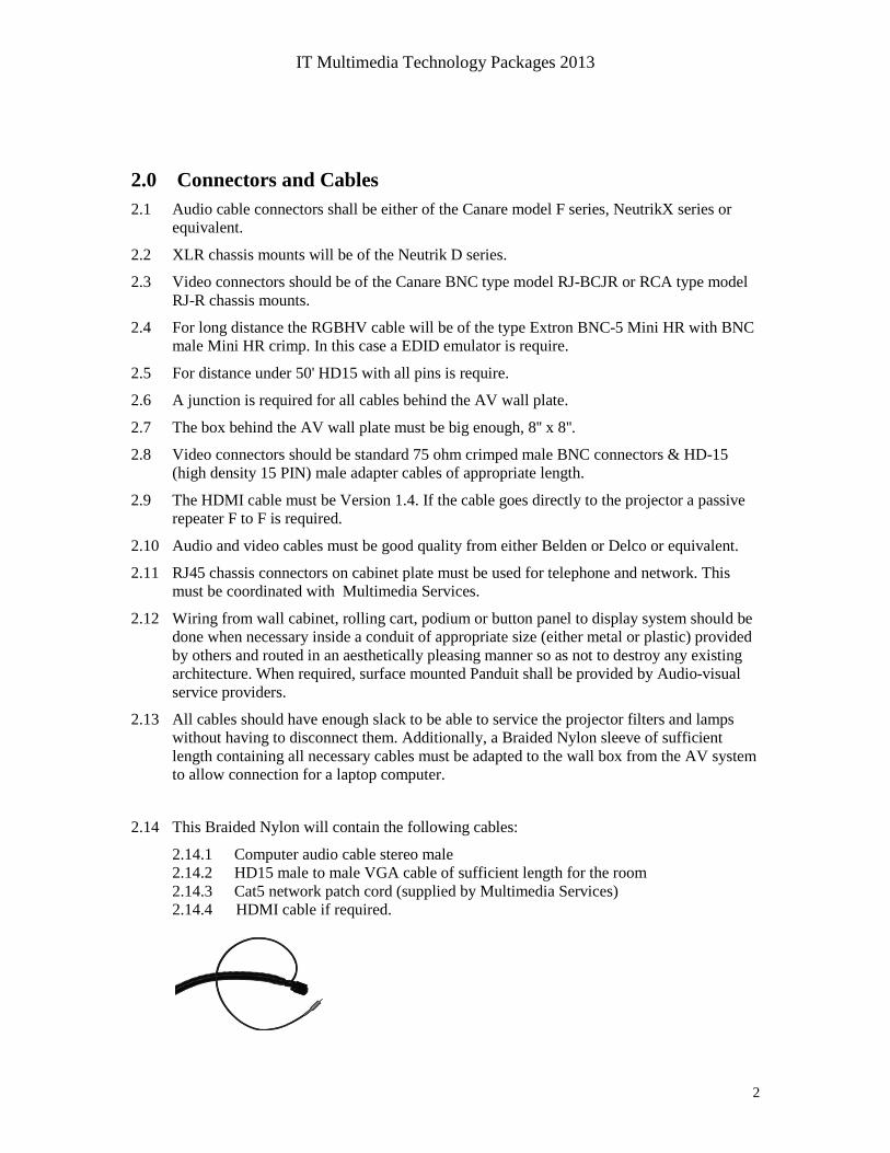
2.13 All cables should have enough slack to be able to service the projector filters and lamps without having to disconnect them. Additionally, a Braided Nylon sleeve of sufficient length containing all necessary cables must be adapted to the wall box from the AV system to allow connection for a laptop computer.
2.14 This Braided Nylon will contain the following cables:
2.14.1 Computer audio cable stereo male 2.14.2 HD15 male to male VGA cable of sufficient length for the room 2.14.3 Cat5 network patch cord (supplied by Multimedia Services) 2.14.4 HDMI cable if required.

IT Multimedia Technology Packages 2013
3
3.0 Security 3.1 Projectors, monitors, document cameras or any other valuable equipment must be secured
with a security anchor cable and lock (Securtech) provided by Multimedia Services.
3.2 Furthermore, all such equipment must be equipped with an alarm system (PCTab) connected to McGill security (done by IT Infrastructure).
3.3 All AV equipment most be tagged with a McGill unique identification number and a list of tag, serial #, brand, model must be filled and return to the Multimedia Services Project Manager.

IT Multimedia Technology Packages 2013
4
4.0 Electrical 4.1 The projector must have a 120vac outlet on or inside the ceiling, switched with a Leviton
1201-L series key switch on the wall, near the AV System, to allow projector reset (by McGill Facilities).
4.2 All Cabinets, Rolling carts, podiums, etc. should have electrical outlets insufficient quantity to power up any and all accessories on or around them, including a laptop.
4.3 All electrical equipment (including contactors, lighting fixtures, dimmers, etc.) should be of selected brands, models, and specifications to conform to campus standards (see Design Standards found on Facilities Operations and Development website at http://www.mcgill.ca/facilities/design/standards).
4.4 All conduits should be of continuous EMT electrical metallic tubing (conduit) type material where possible.
4.5 Areas and situations where EMT is not possible, junction boxes or flexible conduit should be installed only by prior approval of Facilities Operations and Development.
4.6 Junction boxes should not be located in hidden or inaccessible corners.
4.7 All conduit should be at least 1” inside diameter or larger. Larger conduit is generally installed to ensure space for expansion.
4.8 Low voltage cables (e.g. audio, video, and control cables) are all required to run in a separate ¾” conduit from any AC wiring.
4.9 All conduit and electrical circuits should have the same ground reference.

IT Multimedia Technology Packages 2013
5
4.10 All audio, video, computer and control electrical circuits should be fed from “clean” legs from the transformer free of high inductive loads. There should be no elevator motors, compressor motors, blower motors, etc. on the side of the power transformer that feeds the media equipment.
4.11 All electrical control circuits (per classroom) should come to a single location.
4.12 This location should be large enough for the lighting contactor cabinet. When the lights are controlled from a faculty workstation podium, a NEMA type l box that contains the low voltage media control system should be used. This NEMA box of adequate capacity must be fitted with internal threaded studs to accept the panel that the control modules are mounted on.
4.13 The location should be convenient for maintenance and secure from vandalism.
4.14 If possible this location should be isolated from the classroom to eliminate repair and contactor noise.
4.15 A/C outlets on a separate circuit should be provided inside the classroom for the media equipment (i.e. data projectors, portable VCR’s, laptops, audio amplifiers, etc.).
4.16 There should be at least one duplex outlet on each wall, as well as on the front, classroom side, of the projection booth. In larger rooms which have fixed seating on risers, an outlet should be provided in the face of the first riser (centered in the room) for overhead projectors, and on the face of a riser midway back in middle of seating (centered in the room).
4.17 The number and locations of outlets will increase with the size of the room. Consult Multimedia Services for specific requirements pertaining to outlet quantity for audio-visual equipment.
4.18 Whenever possible power and audio/video outlets shall not be floor mounted to avoid the intrusion of water and debris. Outlets shall be mounted on the rear stage wall and/or the front stage wall or other vertical surfaces (such as the risers of tier seating).
4.19 Video Projection - Provide continuous 120V A/C power to the video projector, and a conduit to the projector control station at the front of the classroom and to the projection (or control) booth. This conduit houses a keyed A/C switch, type Leviton 1201-1L to be used to reset the projector in case of lock up.
4.20 In classrooms with dimmable lighting (Lightolier or Lutron), provisions must be made for the appropriate control interface with the Crestron control unit.
4.21 In the case of motorized blinds, a control interface will also be required for the Crestron.
5.0 FACULTY LECTERN/PODIUMS
5.1 All lecterns/podiums are designed by Multimedia Services.
5.2 The Faculty Lecterns for small classrooms should consist of either a small free-standing podium, or a small podium resting on the lecturer’s desk.
5.3 All lecterns must be secured to floor.

IT Multimedia Technology Packages 2013
6
5.4 For large classrooms and Lecture Halls, the lecterns should house controls of audio/visual and public address systems. It should also contain the document camera, DVD/VCR player, contained in a secure locking cabinet. As with the other standardized media packages, the objectives in designing and building the Faculty Lecterns remain a self-service operation, simple, intuitive, with an easy to use interface, off-the-shelf technology, flexibility for integration of future technology, high reliability and fast repair response and to promote interaction with the students. Because of the complexity of these criteria Multimedia Services designs all podiums.

IT Multimedia Technology Packages 2013
7

IT Multimedia Technology Packages 2013
8

IT Multimedia Technology Packages 2013
9
6.0 CRESTRON PROGRAMMING STANDARDS
6.1 All programming code will become the property of McGill University after any project delivery and acceptance.
6.2 For all “standard” classroom installation (see standards defined in Section 7), AV Supplier shall copy programming already done in other similar rooms, and only make modifications as per the specified Statement of Work (SOW).
6.3 Basic Functionality of Crestron system:
6.3.1 For each destination we may need: 6.3.1.1 Video Mute 6.3.1.2 Video Freeze 6.3.1.3 Screen control 6.3.1.4 Auto PC (if required)
6.3.2 We need a Hidden Page. This page will be activated by pressing the system clock, in the home page, for 2 seconds. A password will be required. In this hidden page we need:
6.3.2.1 Master volume control and Audio control for all sources (to adjust their maximum values independently). They all need to be saved in the dead memory to prevent loss if power is lost.
6.3.2.2 Sub Camera page with all the same functions as the user sees (presets 1 to 3), with preset 4 as default.
6.3.2.3 Sub page to change the password. 6.3.2.4 Sub Projector page (to see lamp hours, projector hours and projector status)
6.3.3 We need to be able to control the volume of microphone(s) when the system is OFF, warming UP or Cooling Down.
6.3.4 We need to be able to control the room lighting when the system is OFF, warming UP or cooling down.
6.3.5 When the projector is on standby, it needs to be woken up when a new source is selected.
6.3.6 When the system turns ON, preset 4 on the PTZ camera needs to be called (default).
6.3.7 System needs to be Room View compatible, version 7.2. This is the information we need:
6.3.7.1 Source Selected; 6.3.7.2 Status of the system (ON or OFF); 6.3.7.3 Indication that the system is cooling down or Warming UP (with a
counter); 6.3.7.4 Lamps hours of each projector; 6.3.7.5 Cumulative hours of functioning of projector; 6.3.7.6 Projector status (lamp error or temperature error); 6.3.7.7 Ability to turn OFF the system with “RoomView” Schedule.
6.4 Sound has to follow last input selected.
6.5 Document camera light must be turned OFF only when it’s not selected in any destination (projectors, monitors).

IT Multimedia Technology Packages 2013
10
6.6 Light presets have to be called when a source is selected: 6.6.1 Laptop, PC, Document Camera - Call preset 75% 6.6.2 DVD, Blu-ray, video source - Call preset 25% 6.6.3 System Shut Down - Call preset 100%
6.7 Video Preview is needed for DVD/Blu-Ray and camera (depending on the infrastructure).
6.8 Auto Shut Down has to happen every day at 23:30.
6.9 Clock has to synchronize with McGill NTP (time server) with this address splash.cc.mcgill.ca
6.10 System has to respect daylight saving time zone.
6.11 Link screen must call a separate page with the inputs selection.
6.12 Link screen will turn ON all destinations based on the input selected.
6.13 Need to control each screen and projector power independently.
6.14 Microphone sound limit has to be just below echo threshold.
6.15 When a source is selected for the first time: 6.15.1 Turn on destination(s); 6.15.2 Turn on audio part; 6.15.3 Screen down; 6.15.4 Light preset (if applicable); 6.15.5 Shade preset (if applicable); 6.15.6 Appropriate Input selected for destination; 6.15.7 Appropriate signal route selected (audio and video); 6.15.8 Call Auto PC for RBG source.
6.16 When a source is selected while the system is already ON 6.16.1 Wake up destination; 6.16.2 Light preset (if applicable); 6.16.3 Shade preset (if applicable); 6.16.4 Appropriate input selected for destination; 6.16.5 Appropriate signal route selected (audio and video); 6.16.6 Call Auto PC for RBG source.
6.17 Bargraph volume needs to be synchronized with the system.
6.18 Bragraph volume needs a good representation on the volume 0% (no sound), 50% (mid range), etc…
6.19 On the PTZ camera section, we need to present only presets 1 to 3
6.20 Xpanel IE has to be built for each processor and be the same as the touch panel.
6.21 Network of the processor has to be configured according to IT Infrastructure: 6.21.1 IP address 6.21.2 Subnet mask 6.21.3 Gateway 6.21.4 IP table (not supplied by McGill)
6.22 Aux AV input is always required.
6.23 Page flip option (for certain pages only as defined by McGill) must be used (this is to allow connecting to the system and navigating to needed page without the end user noticing it).

IT Multimedia Technology Packages 2013
11
6.24 DVD / Blu-ray all functions that you see in the screenshot below should work with some extra buttons for the blu-ray player.
6.25 For the doc cam we need to be able to control zoom, manual auto iris, manual auto focus and 3 presets.
6.26 Theme used has to correspond to McGill standard.
6.27 The Shutdown button has a delay of 3 seconds.
6.28 Relay contact for the screen control has to be 2000ms

IT Multimedia Technology Packages 2013
12
6.29 TYPICAL CRESTRON SCREENS: Home/Welcome:
Laptop:(When a specific screen is selected the title must display the screen #).

IT Multimedia Technology Packages 2013
13
PC: (Local computer) (When a specific screen is selected the title must display the screen #).
DVD/VCR: (When a specific screen is selected the title must display the screen #).

IT Multimedia Technology Packages 2013
14
DVD/VCR page 2:
Auxiliary AV: (When a specific screen is selected the title must display the screen #).

IT Multimedia Technology Packages 2013
15
Document Camera: (When a specific screen is selected the title must display the screen #).
PTZ Camera: (When a specific screen is selected the title must display the screen #).

IT Multimedia Technology Packages 2013
16
Page when a source is selected: (Title must correspond to screen selected).
Warning when you Shut Down a specific screen: (Title must correspond to screen selected).

IT Multimedia Technology Packages 2013
17
Audio Control Page:
Lighting Page:

IT Multimedia Technology Packages 2013
18
System Warm UP:
System Cool Down:

IT Multimedia Technology Packages 2013
19
Master Hidden Page:
PTZ Camera Hidden Page:

IT Multimedia Technology Packages 2013
20
Projector Hidden Page:

IT Multimedia Technology Packages 2013
21
7.0 Standard Classroom Packages:
7.1 Basic classroom:
Short throw Projector
Supplied by McGillPowered SpeakerIsolation
Transformer
Crestron MPC-M5Two way communicationXpanel IE, Room View
Writable Wall12' x 5'
POE network JackSupplied by McGill
Input Wall plateLaptop + AudioAux AV + Audio
Standard Installation with a Crestron MPC-M5 processor
View of Wall plate

IT Multimedia Technology Packages 2013
22
8.2 Standard Classroom:

IT Multimedia Technology Packages 2013
23
8.3 Lecture Hall:
COOL Recording computer Supplied by McGill
Auxiliary Input
2 x Sanyo Projectors Supplied by McGill
Crestron TMPC-9
4 x Microphones Input Wallplate
Lutron InterfaceGRX-232
Functionality
- Ability to display any of the sources on any destinations or a combination of destinations
- Last source selected will have the sound
- Need to control: Screens, Light, Doc Cam, Blu-ray, Projectors according to “McGill AV Installation manual”
- COOL Recording computer needs both VGA(from screen1 and screen 2) and master audio out. (Isolation transformer is needed for the audio)
- Room the be automated with Crestron system
- DSP with feedback manager
- Wall Mounted swivel rack with a lockable front door.
- Sympodium ID-370 with Ergotron arm is needed with installation
- All wires, hardware, automation, security, connectors, interface as to correspond to McGill standard according to “McGill AV Installation manual”
- Podium supplied by McGill.
4 x 200 Watts surface mount loudspeaker
QSC AD-S82H or better
Power Amplifier 2 x 180 Watts
Crest-Audio CPX900 or better
Supplied by McGill
Supplied by McGill
Supplied by McGill
Blu-Ray Player Supplied by McGill
Supplied by McGill
2 screens (Silent motor) and LVC
Supplied by McGill