appendix 8.1a calculation of maximum hourly, daily, · pdf fileappendix 8.1a calculation of...
TRANSCRIPT
APPENDIX 8.1A
Calculation of Maximum Hourly, Daily, and Annual Emissions
The following discusses the calculation methodology for project air pollutants and equipment operating assumptions. The following is a summary of the tables presented in this appendix.
8.1A-1 Lean Burn Engine- Equipment Heat Rate
8.1A-2 Typical Natural Gas Composition Analysis
8.1A-3 Natural Gas Consumption per Lean Burn Engine
8.1A-4 Project Operating Assumptions for Lean Burn Engines
8.1A-5 Engine Maximum Hourly and Daily Emissions at Full Load Operations for Lean Burn Engine
8.1A-6 Commissioning Emissions for Each Lean Burn Engine at Four Load Points
8.1A-7 Start-up and Shutdown Emissions Estimates for Each Lean Burn Engine
8.1A-8 Emission Estimates for Lean Burn Engines including Start-up and Shutdown Operations
8.1A-9 Maximum Hourly, Daily, and Annual Criteria Pollutant Emissions for Black Start Diesel Engine
8.1A-10 Maximum Hourly, Daily, and Annual Criteria Pollutant Emissions for Natural Gas Heater
8.1A-11 Federal HAP Annual Emissions for the Lean Burn and Black Start Diesel Engines
8.1A-12 Criteria Pollutant Emission Rates for Refined ISCST3 Modeling
8.1A-13 Expected Average Annual Operating Hours (30-year period) and Annual PM10 Emissions for Mitigation
In addition to the above tables, other miscellaneous support data for the device-specific emissions calculations is also included in this Appendix. These are as follows:
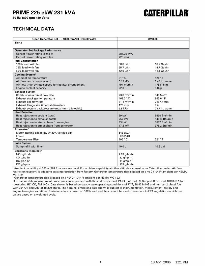
• Black Start Diesel Engine – Caterpillar engine equipment description
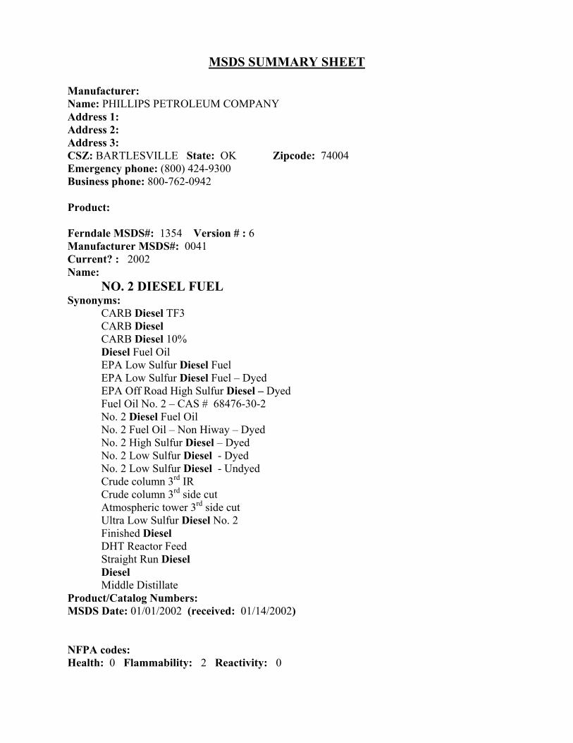
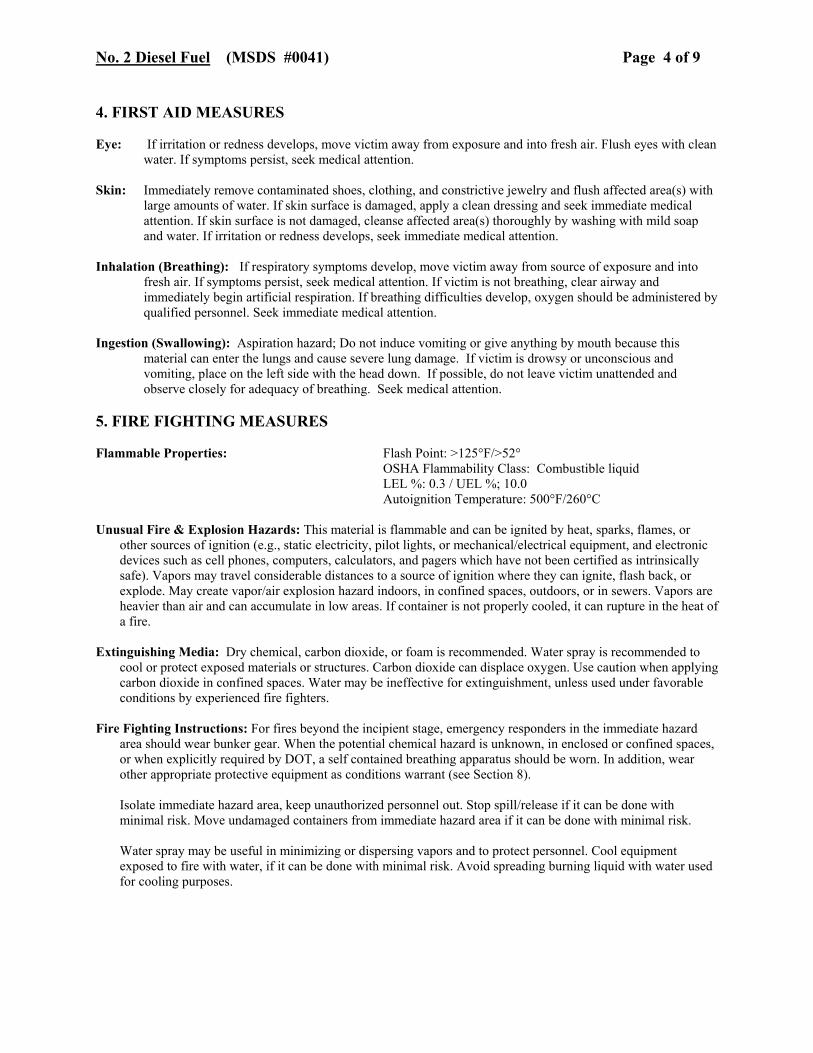
• CARB Diesel Fuel Oil – Sample Material Data Safety Sheet of CARB fuel oil. Ultra low sulfur diesel fuel oil with not more than 15 ppm sulfur by weight will be used for the black start diesel engine fuel.
• 2005 Source Test Results – Source test summary report, which includes PM10 emission test results, for the Barrick facility located in McCarran, Nevada. Fourteen engines, Wärtsilä 20V34SG, firing solely natural gas are operated at Barrick.
It should be noted that slight differences in calculated values are expected because precedent values (as presented in these tables) have been rounded-off to calculate the dependent values.
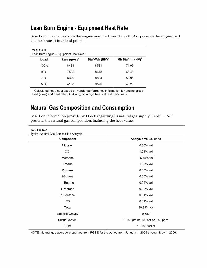
Lean Burn Engine - Equipment Heat Rate Based on information from the engine manufacturer, Table 8.1A-1 presents the engine load and heat rate at four load points.
TABLE 8.1A Lean Burn Engine – Equipment Heat Rate
Load kWe (gross) Btu/kWh (HHV) MMBtu/hr (HHV)1
100% 8439 8531 71.99
90% 7595 8618 65.45
75% 6329 8834 55.91
50% 4198 9576 40.20 1 Calculated heat input based on vendor performance information for engine gross load (kWe) and heat rate (Btu/kWh), on a high heat value (HHV) basis.
Natural Gas Composition and Consumption Based on information provide by PG&E regarding its natural gas supply, Table 8.1A-2 presents the natural gas composition, including the heat value.
TABLE 8.1A-2 Typical Natural Gas Composition Analysis
Component Analysis Value, units
Nitrogen 0.86% vol
CO2 1.04% vol
Methane 95.75% vol
Ethane 1.90% vol
Propane 0.30% vol
i-Butane 0.05% vol
n-Butane 0.05% vol
i-Pentane 0.02% vol
n-Pentane 0.01% vol
C6 0.01% vol
Total 99.99% vol
Specific Gravity 0.583
Sulfur Content 0.153 grains/100 scf or 2.58 ppm
HHV 1,018 Btu/scf
NOTE: Natural gas average properties from PG&E for the period from January 1, 2005 through May 1, 2006.

Calculations for fuel consumption (e.g., scf/hr, MMscf/year) are based on the engine heat input (MMBtu/hr) and the natural gas heat value of 1,018 Btu/scf (HHV). The results are presented in Table 8.1A-3.
TABLE 8.1A-3 Natural Gas Consumption per Lean Burn Engine
Load MMBtu/hr scf/hr1 MMBtu/day MMBtu/yr1,2 Therms/yr2,3
100% 71.99 70720 1728 287,972 2,879,724
90% 65.45 64296 1571 261,815 2,618,148
75% 55.91 54922 1342 223,642 2,236,415
50% 40.20 39489 965 160,800 1,608,002 1 Slight difference in value from what otherwise might be expected is due to round-off of the input value used to calculate the dependent value. 2 A year is limited to 4,000 operating hours. 3 The conversion from Btu to therms is based on 100,000 Btu per therm.
Operating Assumptions – Lean Burn Engines Table 8.1A-4 summarizes the assumptions for maximum and expected average operations for each lean burn engine. Additional operating assumptions also are provided
TABLE 8.1A-4 Project Operating Assumptions for Lean Burn Engines
Parameter Value / Attribute
Maximum (worst-case) daily operating hours 24
Maximum (worst-case) annual operating hours 4,000
Expected average daily operating hours <<24; dependent upon PG&E dispatch pattern
Expected average annual operating hours (30 year period) Approximately 1,740
Maximum number of annual start-ups/shutdowns per engine 300
Commissioning duration 50-80 operating hours/engine
Vendor Guarantee and Emission Assumptions – Criteria Pollutants The following presents the emission calculation method for hourly emissions at full load operations, commissioning emissions, and start-up and shutdown emissions.
Hourly and Daily Emissions at Full Load Operations – Lean Burn Engines For typical emissions, each of the five criteria pollutant emissions is based on engine manufacturer information and site-specific characteristics, which were used to calculate typical emissions performance data for the lean burn engines at three temperatures – 32°F, 59°F, and 100°F – and at the four operating load points - 50%, 75%, 90%, and 100% load. Additionally, as part of the performance data, other information also was provided by the manufacturer, e.g., heat rate, exhaust gas flow, exhaust temperature, etc., which was used as the initial basis for air quality modeling purposes.
The site-specific natural gas composition is presented above; this information is assumed in determining the POC and SO2 emission rates.
The F-factor calculation method is used to calculate the hourly emission rate for NOx, CO, and POC emissions. Conversion factors used as part of the F-factor calculation method are presented in the next section. Other conversion factors assumed include:
453.593 grams per lb (g/lb) 7,000 grains per lb (gr/lb) 9.486E-04 Btu per Joule (Btu/J) 0.7457 kilowatt per horsepower (kw/hp)
F-Factor Calculation Method As part of Wärtisilä’s performance data, mass emission estimates (lbs/hr) were initially provided, based on an F-factor calculation methodology, found in 40 CFR Part 60, Appendix A, Method 19. The vendor’s information assumed:
F-Factor (initially assumed by vendor) = 2.34 x 10E-07 dscm/Joule (dscm/J), where: dscm refers to dry standard cubic meter
To reflect site characteristics firing natural gas, the F-factor assumed:
F-Factor (natural gas) = 2.43 x 10E-07 dscm/J
The initial calculation for NOx emissions for converting NOx in ppm units to ng/J of NOx assumed the given conversion:
NO2 (for NOx) conversion = 1.91 x 10E+06 ng NOx/scm where: ng refers to nanogram; scm refers to standard cubic meter
NOx Emissions (Maximum Hourly at Full Load) – Lean Burn Engine A vendor guarantee of 5 ppmvd NOx at 15 percent O2 was provided. This is equivalent to an hourly emission rate of 1.38 lbs/hr as follows:
(5 ppm) * (2.43x10E-07 dscm/J) * (1.91x10E+06 ng NOx/scm) * (20.9/(20.9-15)) = 8.23 ng/J NOx = 1.38 lbs/hr of NOx = 33.05 lbs/day of NOx

The molecular weight of NO2, used to represent the estimate for NOx emissions, is 46 lb/lb-mol. This molecular weight is used in the calculation methodology for CO and POC emissions.
CO Emissions (Maximum Hourly at Full Load) – Lean Burn Engine The molecular weight of CO is 28 lb/lb-mol. A vendor guarantee of 13 ppmvd CO at 15 percent O2 was provided. This is equivalent to an hourly emission rate of 2.18 lbs/hr as follows:
(13 ppm) * (2.43x10E-07 dscm/J) * (1.91x10E+06 ng NOx/scm) * (28/46) * (20.9/(20.9-15)) = 13.02 ng/J CO = 2.18 lbs/hr of CO = 52.30 lbs/day of CO
The ratio of the molecular weight of CO to NOx (or 28/46) is used to calculate the effective CO conversion factor (ng CO/scm).
POC Emissions (Maximum Hourly at Full Load) – Lean Burn Engine The molecular weight of CH4 (to estimate POC) is 16 lb/lb-mol. A vendor guarantee of 25 ppmvd POC at 15 percent O2 was provided. This is equivalent to an hourly emission rate of 2.39 lbs/hr as follows:
(25 ppm) * (2.43x10E-07 dscm/J) * (1.91x10E+06 ng NOx/scm) * (16/46) * (20.9/(20.9-15)) = 11.45 ng/J POC = 2.39 lbs/hr of POC = 57.47 lbs/day of POC
The ratio of the molecular weight of CH4 to NO2 (or 16/46) is used to calculate the effective CH4 conversion factor (ng CH4/scm). The resulting value is assumed to be the equivalent of the POC value.
It is noted that the engine manufacturer provided a summary of POC concentration levels (in ppm) based on the natural gas specifications. The flue gas concentration is dependent upon the sum of the constituents of propane, butane, pentane, and hexane in the natural gas. The vendor guarantee of 25 ppm accounts for the sum of these site-specific constituents.
PM10/2.5 Emissions (Maximum Hourly at Full Load) – Lean Burn Engine The vendor indicated that it is appropriate to assume that nearly all PM10 is PM2.5 for this engine. The engine manufacturer provided a PM10 emissions guarantee of 2.426 lbs/hr of PM10 at full load operations. The daily emission rate is estimated at 58.22 lbs/day PM10.
SO2 Emissions (Maximum Hourly at Full Load) – Lean Burn Engine Based on engine manufacturer information, the SO2 emissions are the sum of SO2 as a result of natural gas combustion and as a result of the presence of lube oil. The vendor provided 0.2 lb/hr of SO2 emission rate for the contribution from lube oil.
The SO2 emissions from natural gas combustion are based on site-specific natural gas information relating to the total sulfur content. Based on the typical natural gas composition in Table 8.1A-2, the average annual total sulfur is 0.153 grains/100 scf (or more specific at

0.1525 grains/100 scf). Additional values that contribute to this SO2 emission estimate include the natural gas heat value, the engine heat input, and the molecular weights of SO2
and S. With this information, the equivalent hourly emission rate of 0.03 lbs/hr is calculated as follows:
(0.153 grains of S/100 scf) / (1,018 Btu/scf) * (10E+06 Btu/MMBtu) / (7,000 grains/lb) * (64.06 lb SO2/lb-mol)/(32.06 lb S/lb-mol) * (71.99 MMBtu/hr) = 0.03 lbs/hr of SO2 from natural gas combustions.
Therefore, the total SO2 emission rate is 0.23 lbs/hr of SO2, and 5.52 lbs/day of SO2.
Based on the above information, the following Table 8.1A-5 summarizes the maximum hourly and daily emissions from each engine during full load operations.
TABLE 8.1A-5 Engine Maximum Hourly and Daily Emissions at Full Load Operations for Lean Burn Engine
Emission ppmvd @ 15% O2
Maximum Hourly, (Each Engine)
Lb/hr
Daily, (Each Engine)
Lbs/day4
NOx1, 2 5 1.38 33.05
CO1,2 13 2.18 52.30
POC1,2,3 25 2.39 57.47
PM10/2.51 NA 2.43 58.22
SO21, 3 NA 0.23 5.52
1 Based vendor guarantee information 2 Based on F-factor calculation 3 Based on natural gas composition. (See Table 8.1A-2) 4 Assumes 24 hours per day. Does not include start-up and shutdown emissions.
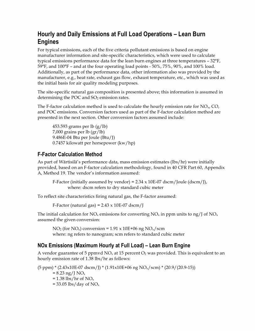
Commissioning Emissions – Lean Burn Engines The engine manufacturer provided concentrations (ppm or mg/Nm3) for NOx, CO, POC, and a PM10 emission rate, for use during commissioning at four load points – 100%, 90%, 75%, and 50%. For SO2 emissions, it is assumed that the hourly commissioning value is the same as at full load operations. Given commissioning concentrations, a ratio of these values with the corresponding hourly emission values at full load (based on the F-factor calculation method) was used to estimate the hourly emissions during commissioning. The calculation method is as follows:
[(Commissioning, ppm) / (Hourly, ppm at full load)] * (Hourly, lb/hr at full load) = Commissioning, lbs/hr
The ppm values at full load and resulting hourly emissions at full load are presented in Table 8.1A-5. Below, Table 8.1A-6 summarizes the results of the above calculation method to determine the hourly emissions during commissioning.
TABLE 8.1A-6 Commissioning Emissions for Each Lean Burn Engine at Four Load Points1
Pollutant 100% 90% 75% 50%
NOx2 120 ppm
33.05 lbs/hr 120 ppm
33.05 lbs/hr 110 ppm
30.29 lbs/hr 100 ppm
27.54 lbs/hr
CO2 260 ppm 43.58 lbs/hr
260 ppm 43.58 lbs/hr
300 ppm 50.29 lbs/hr
400 ppm 67.05 lbs/hr
POC2 110 ppm 10.54 lbs/hr
110 ppm 10.54 lbs/hr
140 ppm 13.41 lbs/hr
170 ppm 16.28 lbs/hr
PM103 25 mg/Nm3 2.48 lbs/hr
25 mg/Nm3 2.48 lbs/hr
30 mg/Nm3 2.98 lbs/hr
40 mg/Nm3 3.97 lbs/hr
SO24 0.23 lb/hr 0.23 lb/hr 0.23 lb/hr 0.23 lb/hr
1 Concentration emissions in ppm and mg/Nm3 are based on 15% O2, by volume, dry, as provided by engine manufacturer; Nm3 refers to “Normal cubic meter.” 2 Hourly emission values were calculated based on engine manufacturer’s F-factor calculations. 3 Hourly emission values were provided by engine manufacturer (rather than a calculated value). 4 Assumed to be the same as during normal full load operations. (See Table 8.1A-5)
Start-up and Shutdown Emissions – Lean Burn Engines The engine manufacturer provided NOx, CO, POC and PM10 emission estimates (e.g. estimates for the emissions that would result prior to the SCR and oxidation catalyst systems being in normal operation) for a cold catalyst start-up, a warm catalyst start-up, and shutdown operating scenarios. For SOx emissions, the full load emissions were assumed as a basis.
For start-up emission estimates, a combination of engine manufacturer information, a review of operating information from a facility with a similar engine, and engineering judgment were considered to estimate emissions. The duration of a cold catalyst start-up is estimated at 30 minutes. The duration of a warm catalyst start-up is estimated at 15 minutes.
For shutdown emission estimates, a combination of engine manufacturer information and the hourly emissions at full load were used to estimate emissions. The manufacturer indicated an estimate of 8.5 minutes for the duration of a shutdown. The hourly emissions at full load (Table 8.1A-5) were multiplied by a factor of 8.5 minutes/60 minutes.
Table 8.1A-7 presents estimated start-up and shutdown emissions for a lean burn engine.
TABLE 8.1A-7 Start-up and Shutdown Emissions Estimates for Lean Burn Engines (each engine)
Pollutant Cold catalyst start,
lbs/start
Warm catalyst start,
lbs/start
Shutdown period,
lb/shutdown
Cold start-up cycle,1
lbs/event
Warm start-up cycle,2
lbs/event
NOx 9.17 2.52 0.20 9.36 2.71
CO 13.76 2.38 0.31 14.06 2.60
POC 6.87 1.90 0.34 7.21 2.17
SOx3 NA3 NA3 NA3 NA3 NA3
PM10/2.5 2.52 2.06 0.35 2.87 2.41

1 A cold catalyst start-up cycle is defined as a cold start followed immediately by shutdown of the engine. A cold catalyst start-up occurs when the catalyst is at or below 25°C. The cold start-up cycle is estimated to be a total of 38.5 minutes. 2 A warm catalyst start-up cycle is defined as a warm catalyst start followed immediately by shutdown of the engine. A warm catalyst start-up occurs when catalyst temperature is at least 270°C. The warm start-up cycle is estimated to be a total of 23.5 minutes. 3 NA means not available from the manufacturer. The SOx emissions during start-up and shutdown are assumed to be no greater than emissions under normal full load operations. (See Table 8.1A-5)
Annual Emissions at Maximum Operations – Lean Burn Engines The maximum annual emissions are based on the maximum annual operating hours, which include the maximum number of cold starts. Table 8.1A-4 presents project operating assumptions. Table 8.1A-5 presents hourly emissions from full load operations. Table 8.1A-7 presents start-up, shutdown, duration of events, and start-up cycle emission estimates. Cold start-up emissions are greater than warm-startup emissions. Based on this information, the annual emissions are estimated by the following methodology:
• Annual cold start-up and shutdown operations – Determine the total hours for 300 cold start-up and shutdown (S/S) events, i.e., S/S events. With a cold start-up cycle of 38.5 minutes, the total hours associated with S/S time is 192.50 hours.
• Annual full load operations – Determine the total hours for full load (FL) operations by subtracting the S/S events from 4,000 hours, i.e., FL time. As a result, the total hours associated with FL time is 3,807.50 hours per year.
• Annual S/S pollutant emissions – Determine each pollutant’s emissions by multiplying the cold start-up cycle emission value (Table 8.1A-7) by 300 events per year.
• Annual full load emissions – Determine each pollutant’s emissions by multiplying the FL emission value (Table 8.1A-5) by the annual FL hours.
• Total annual emissions – Add the S/S pollutant emissions and FL emission values for the annual emissions.
• Total daily emissions – Based on annual emissions (tons/year) with an assumed 24 hours/day operation (worst case) or 166.67 days year. (Note that expected normal average daily operating hours are expected to be much less than 24, and therefore, daily operating hours will be dependent upon PG&E’s dispatch pattern.)
Table 8.1A-8 presents a summary of the maximum annual emission estimates for each lean burn engine.
TABLE 8.1A-8 Emission Estimates for Lean Burn Engines including Start-up and Shutdown Operations
Pollutant
Cold start-up cycle
(Each Engine) Lb/event per yr
Full Load (Each Engine)
Lb/hr
Total Annual Emissions
(Each Engine) tons/year
Total Annual Emissions
(14 Engines) tons/year
Total Daily Emissions
(14 Engines) tons/day1
NOx 9.36 1.38 4.02 56.34 0.34
CO 14.06 2.18 6.23 87.27 0.52

POC 7.21 2.39 5.62 78.74 0.47
PM10/2.5 2.87 2.426 5.05 70.67 0.42
SOx n/a2 0.23 0.46 6.44 0.42 1 Daily emissions represent the total annual emissions of all 14 engines (Appendix 8.1A, Table 8.1A-8) at a worst-case assumption of 24 hours per day operation, or a calculated 166.7 days per year.
Black Start Diesel Engine Criteria Pollutant Emissions The proposed black start diesel engine emissions are based on engine vendor data and ultra low sulfur diesel fuel oil characteristics. Engine characteristics and operations relevant for determining the engine’s emissions include the following:
• Engine bhp: approximately 302 hp (based on net output)
• Fuel: ultra-low sulfur diesel fuel at no greater than 0.0015% sulfur by weight (or 15 ppm)
• Fuel consumption: 18.2 gallons/hour
• Fuel oil density: 7.05 lbs/gallon
• Daily operations: not more than one (1) hour per day
• Annual operations: not more than thirty (30) hours per year
Emissions, based on vendor data, fuel use, and operations are summarized in Table 8.1A-9.
TABLE 8.1A-9 Maximum Hourly, Daily, and Annual Criteria Pollutant Emissions for Black Start Diesel Engine
Pollutant Emission Factor (grams/bhp-hr)1
Max Hour Emissions,
lbs
Max Daily Emissions,
lbs
Max Daily Emissions,
tons
Max Annual Emissions,
tons
NOx 2.69 1.79 1.79 2.68E-02 2.68 E-02
CO 0.32 0.21 0.21 3.19E-03 3.19 E-03
POC 0.11 0.07 0.07 1.10E-03 1.10 E-03
SOx2 NA 0.0038 0.0038 5.77E-05 5.77 E-05
PM10/2.53 0.159 0.11 0.11 1.59E-03 1.59 E-03 1 Based on black start diesel engine vendor data. 2 Based on fuel oil sulfur content no greater than 0.0015% sulfur by weight. 3 All PM10 emissions are assumed to be PM2.5.
For pollutant emissions provided in grams/bhp-hr, the calculation methodology for hourly, daily, and annual emissions of NOx, CO, POC and PM10/2.5 is as follows:
(Emission Factor for a pollutant, grams/bhp-hr) * (Engine, bhp) * (lb/453.593 grams) = lb/hr pollutant emissions = lb/day pollutant emissions

(Pollutant Emissions, lb/hr) * (30 hrs/yr) * (ton/2000 lb) = tons/yr pollutant emissions
(Emission Factor for a pollutant, grams/bhp-hr) * (Engine, bhp) * (lb/453.593 grams) * (30 hrs/yr) * (ton/2000 lb) = tons/year pollutant emissions
For the SO2 emission estimate, given ultra low sulfur diesel fuel oil at no greater than 0.0015% sulfur by weight (or 15 ppm), the calculation methodology for hourly and annual is as follows:
(18.2 gallons fuel oil/hr) * (7.05 lbs/gal) * (0.000015 S) (64.06 lb SO2 /lb-mol)/(32.06 lb S/lb-mol) = 0.0038 lbs/hr of SO2 = 0.0038 lbs/day of SO2
(0.0038 lbs of SO2 /hour) * (30 hrs/yr) * (ton/2000 lb) = 5.77E-05 tons/year of SO2
Natural Gas Heater – Criteria Emissions A natural gas heater, if installed, would be sized somewhere within a range of 4.00-7.15 MMBtu/hr (HHV). The heater would be fired solely on natural gas and would operate no more than the hours of operation of the lean burn engines. Heater characteristics and operations relevant for determining the heater emissions include the following:
• Heat input: approximately 7.15 MMBtu/hr (HHV), maximum
• Natural gas heat value: 1,018 Btu/scf (HHV), see Table 8.1A-2
• Daily operations: not more than 24 hours per day
• Annual operations: not more than 4,000 hours per year
Table 8.1A-10 presents the maximum hourly, daily, and annual emissions assuming emission factors for stationary external combustion units from US EPA AP-42.
TABLE 8.1A-10 Maximum Hourly, Daily, and Annual Criteria Pollutant Emissions for Natural Gas Heater
Pollutant Emission Factor lb/MMscf1
Max Hour Emissions, lbs
Max Daily Emissions, lbs2
Max Annual Emissions, tons3
NOx 100 0.70 16.86 1.40
CO 84 0.59 14.16 1.18
POC 5.5 0.04 0.93 0.08
SOx 7.6 0.05 1.28 0.11
PM10/2.5 0.6 0.0042 0.10 0.01 1 Based on the natural gas composition. (See Table 8.1A-2) 2 Assumes up to 24 hours per day. 3 Assumes up to 4,000 hours per year.

Hazardous Air Pollutant Emissions – Lean Burn and Black Start Diesel Engines Table 8.1A-11 presents the summary of the estimated hazardous air pollutant (HAP) emissions from the lean burn gen sets and the black start diesel engine. The substances are those that the federal US EPA has designated as HAP emissions. The listed substances represented polycyclic organic materials, organics, and metals. Emission factors are presented in Sec. 8.6, Public Health, for these engines.
These emissions were estimated for information purposes, as support for the regulatory determination that the federal US EPA regulatory requirement to address HAP emissions is not applicable. The facility is not a major source of HAPs. An individual substance’s annual emissions are no greater than 10 tons per year; the annual emissions of the total of the HAP substances are no greater than 25 tons per year.
As noted above, the fuel use consumption for the black start diesel engine is estimated at 18.2 gallons per hour (or approximately 18 gal/hr). The engine will operate not more than 30 hours per year. Emission factors are provided in units of pounds per 1000 gallons of fuel. For the annual black start diesel engine HAP emissions, the calculation methodology is as follows:
(Emission factor, lb/1000 gal) * (Fuel use, ~18 gal/hour) * (30 hours/year) * (ton/2000 lb) = ton/year of HAP substance
As noted above, the heat input of each lean burn engine is 71.99 MMBtu/hr (or approximately 72 MMBtu/hr (HHV)). Each lean burn engine will operate not more than 4,000 hours per year. There are a total of 14 engines. Emission factors are provided in units of pounds per MMBtu. For the annual lean burn gen set HAP emissions, the calculation methodology is as follows:
(Emission factor, lb/MMBtu) * (Heat input, ~72 MMBtu/hr) * (4,000 hours/year) * (ton/2000 lb) * (Number of engines, 14 engines) = ton/year of HAP substance for all lean burn engine
TABLE 8.1A-11 Federal HAP Annual Emissions for the Lean Burn and Black Start Diesel Engines1
Substance
CAS or
Category
Black Start Diesel Engine2
lb/yr
14 Engine Generators3
lb/yr Total HAPs,
lb/yr Total HAPs,
tons/yr
Polycyclic Organic Material (POM)4
Acenaphtene POM 3.62E-04 3.58E-01 3.58E-01 1.79E-04
Acenapthylene POM 5.51E-04 1.24E+00 1.24E+00 6.22E-04
Anthracene POM 1.20E-04 2.82E-01 2.82E-01 1.41E-04
Benz(a)anthracene POM 5.18E-05 1.39E-01 1.40E-01 6.98E-05
Benzo(a)pyrene POM 4.27E-05 6.40E-03 6.44E-03 3.22E-06
Benzo(a)fluoranthene POM 6.05E-05 -- 6.05E-05 3.02E-08

Benzo(b)fluoranthene POM -- 9.70E-02 9.66E-02 4.83E-05
Benzo(g,h,i)perylene POM 4.86E-05 1.79E-02 1.80E-02 8.97E-06
Benzo(k)fluoranthene POM 4.23E-05 1.86E-02 1.86E-02 9.30E-06
Chrysene POM 7.02E-05 3.39E-02 3.40E-02 1.70E-05
Dibenz(a,h)anthracene POM 4.43E-05 6.40E-03 6.45E-03 3.22E-06
Fluoranthene POM 1.78E-04 6.90E-01 6.91E-01 3.45E-04
Fluorene POM 5.21E-04 1.03E+00 1.03E+00 5.17E-04
Indeno(1,2,3-cd)pyrene POM 4.56E-05 1.70E-02 1.70E-02 8.51E-06
Naphthalene POM 8.64E-03 5.95E+01 5.96E+01 2.98E-02
Phenanthrene POM 1.91E-03 4.38E+00 4.39E+00 2.19E-03
Pyrene POM 1.43E-04 4.44E-01 4.44E-01 2.22E-04
Organics
Ethylbenzene 100414 3.65E-03 1.69E+02 1.69E+02 8.45E-02
1,3-Butadiene 106990 -- 8.70E+02 8.74E+02 4.37E-01
Acetaldehyde 75070 1.87E-03 1.25E+03 1.25E+03 6.25E-01
Acrolein 107028 5.78E-04 1.40E+02 1.40E+02 7.00E-02
Benzene 71432 9.77E-02 5.17E+02 5.17E+02 2.59E-01
Formaldehyde 50000 2.75E-02 1.12E+04 1.12E+04 5.60E+00
Toluene 108883 3.29E-02 5.67E+02 5.67E+02 2.84E-01
Xylenes 1330207 1.13E-02 1.53E+03 1.53E+03 7.65E-01
Hexane 110543 7.51E-04 -- 7.51E-04 3.75E-07
Metals5
Arsenic 0 8.64E-04 -- 8.64E-04 4.32E-07
Cadmium 0 8.10E-04 -- 8.10E-04 4.05E-07
Chromium VI 0 5.40E-05 -- 5.40E-05 2.70E-08
Lead 0 4.48E-03 -- 4.48E-03 2.24E-06
Manganese 0 1.67E-03 -- 1.67E-03 8.37E-07
Mercury 0 1.08E-03 -- 1.08E-03 5.40E-07
Nickel 0 2.11E-03 -- 2.11E-03 1.05E-06
Selenium 0 1.19E-03 -- 1.19E-03 5.94E-07
Total Tons per Year of POM, Organics, Metal Substances 8.14E+00 1 Reference: CAA Section 112(b)(1) Initial List, with modifications as noted on the US EPA’s Air Toxics Website: http://www.epa.gov/ttn/atw/orig189.html. 2 Based on US EPA AP-42 emission factors and black start engine operating scenario. The initial emission estimates in this table are based on ~18 gal/hr. 3 Based on CARB CATEF natural gas emission factors for POM and organics, AP-42 emission factors for metals, and assumes 40% organics control for 14 engines operated 4,000 hours per year. The initial emission estimates in this table are based on ~72 MMBtu/hr.

4 POM includes organic compounds with more than one benzene ring, and which have a boiling point greater than or equal to 100ºC. 5 Includes metals and metals’ compounds. EPA’s HAP list shows CAS as “0.” Beryllium is listed as a compound in the US EPA’s list, however, there is not an available emission factor; therefore, it is not included in the above summary.
Ammonia Slip Emissions The proposed ammonia slip emissions estimate, from the SCR system, is 20 ppmvd at 15 percent O2. This is presented in Table 8.1F-2, Comparison of Eastshore Proposed BACT to the BAAQMD BACT Guidelines, in Appendix 8.1F (Evaluation of Best Available Control Technology). The following summarizes the calculation methodology as an estimation of ammonia slip mass emission rate on an hourly and annual basis, based on the operating assumptions (Table 8.1A-3), the engine heat rate, and the F-factor calculation method. The molecular weight of ammonia is assumed to be 17 lb/lb-mole.
F-factor (natural gas) = 8,710 dscf/MMBtu (in English units) where: dscf refers to dry standard cubic feet
NO2 (for NOx conversion) = 1.194 x 10E-07 lb NO2/dscf
(20 ppm) * (8,710 dscf/MMBtu) * (1.194 x 10E-07 lb NO2/dscf) * (17/46) * (20.9/(20.9-15)) = 0.027 lb/MMBtu = 1.96 lb/hr of ammonia per engine (based on engine heat input) = 3.92 tons/year of ammonia per engine (based on 4,000 annual operating hours) = 54.89 tons year of ammonia for all 14 engines
It should be noted that alternative methods also can be used to calculate this value. This is presented for the purposes of estimating ammonia emissions used in the health risk assessment evaluation (See Appendix 8.1D.)
Worst-Case Emissions Estimates for the Modeled Averaging Periods Emission impacts from criteria pollutants are determined for those pollutants for which a state or federal ambient air quality standard (AAQS) exists. These include the following:
• CO – 1-hour and 8-hour
• SO2 – 1-hour, 3-hour, 24-hour, and annual
• PM10 – 24-hour and annual
• NO2– 1-hour and annual
For the lean burn engines, engine start-up and shutdown emissions (Table 8.1A-7) were accounted for in the analysis for all short-term (24-hours or less) and long-term (annual) averages in the air quality modeling. Because the start-up time for each engine is 30 minutes or less, the worst-case 1-hour impact analysis modeling accounted for 30 minutes in cold

start-up followed by 30 minutes in full load. In addition, all fourteen (14) engines were assumed to startup simultaneously. For longer averaging periods such as the 3-hour, 8-hour, and 24-hour averaging times, multiple start-ups/shutdowns along with full load operation for all fourteen (14) engines were modeled in order to calculate the worst-case impacts.
For the black start diesel engine, full load operating emissions (Table 8.1A-9) were assumed.
The following describes, for each pollutant, the operating scenario that was used to calculate the respective worst-case emissions. Other cases considered are presented in Appendix 8.1B.
CO Emissions For the lean burn engines, the cold catalyst start-up CO emissions are greater than the full load, hourly CO emissions. For the black start diesel engine, the full load, hourly CO emission rate is the maximum emissions.
• 1-hour CO – Lean Burn Engine: Cold catalyst start-up with the remainder of the hour at full load operations. (13.76 lb/hr) + [(30 min/60 min) * (2.18 lb/hr)] = 14.85 lbs for 1-hour = 14.85 lb/hr = 1.87 grams per sec (g/s) of CO for 1-hr averaging (avg.) period for lean burn
• 8-hour CO – Lean Burn Engine: 1st hour with cold catalyst start-up with remainder of the hour at full load operation. The remaining 7-hours (or 420 minutes) are a series of warm catalyst start-up cycles. (A warm start-up cycle duration is 23.5 minutes.) (13.76 lb/hr) + [(30 min/60 min) * (2.18 lb/hr)] + [(15.56 cycles) * (2.60 lbs/cycle)] = 55.95 lbs for 8-hour = 6.99 lb/hr = 0.88 g/s of CO for 8-hr avg. period for lean burn For the purposes of modeling a worst-case for this pollutant, the CO unit value of 1.87 g/s of CO was used for the 8-hour modeling analysis.
• 1-hour CO – Black Start Diesel Engine: 1-hour full load operations. (0.21 lb/hr) = 0.21 lb for 1-hour = 0.0265 g/s of CO for 1-hr avg. per black start
• 8-hour CO – Black Start Diesel Engine: 8-hour full load operations. (0.21 lb/hr) = 0.21 lb for 8-hour (to be divided by 8 and converted to g/s) = 0.0034 g/s of CO for 8-hr avg. period for black start
SO2 Emissions For the lean burn and black start diesel engines, the full load, hourly SO2 emission rate is the highest emissions. Therefore, the resulting emission rates are as follows for the four averaging periods:
• 1-hour SO2 – Lean Burn: 1-hour full load operations. (0.23 lb/hr) = 0.030 g/s of SO2 for 1-hr avg. period for lean burn.

• 3-hour SO2 – Lean Burn: 3-hours at full load operations during a 3-hour period (0.23 lb/hr) * 3 = 0.60 lbs of SO2 for 3-hr avg. period = 0.23 lb/hr = 0.030 g/s of SO2 for 3-hr avg. period for lean burn
• 24-hour SO2 – Lean Burn: 24-hours at full load operations during a 24-hour period (0.23 lb/hr) * 24 = 5.52 lbs of SO2 for 24-hr avg. period = 0.23 lb/hr = 0.030 g/s of SO2 for 24-hr avg. period for lean burn
• Annual SO2 – Lean Burn: 4,000 hours at full load operations during a year or during 8,760 hours per year. (0.23 lb/hr) * 4,000 = 920 lbs of SO2 for annual avg. period = 0.11 lb/hr = 0.0132 g/s of SO2 for annual avg. period for lean burn
• 1-hour SO2 – Black Start Diesel Engine: 1-hour full load operations. (0.0038 lb/hr) = 0.000479 g/s of SO2 for 1-hr avg. period for black start
• 3-hour SO2 – Black Start Diesel Engine: 1-hour operations during a 3-hour period (0.0038 lb/hr) * (1) = 0.0038 lb of SO2 (to be divided by 3 and converted to g/s) = 0.00016 g/s of SO2 for 3-hr avg. period for black start
• 24-hour SO2 – Black Start Diesel Engine: 1-hour operations during a 24-hour period (0.0038 lb/hr) * (1) = 0.0038 lb of SO2 (to be divided by 24 and converted to g/s) = 0.00002 g/s of SO2 for 24-hr avg. period for black start
• Annual SO2 – Black Start Diesel Engine: 30 hours of operations during a year (0.0038 lb/hr) * (30) = 0.114 lb of SO2 (to be divided by 8760 and converted to g/s) = 0.000002 g/s of SO2 for annual avg. period for black start
PM10 Emissions For the lean burn engines, the cold catalyst start-up PM10 emissions are greater than the full load, hourly PM10 emissions. For the black start diesel engine, the full load, hourly PM10 emission rate is the maximum emissions.
• 24-hour PM10 – Lean Burn Engine: 1st hour with cold catalyst start-up with the remainder of the hours at full load operations. The remaining 23-hours in full load operations. (2.52 lbs/hr) + [(30 min/60 min) * (2.426 lbs/hr)] + [23 hours * (2.426 lbs/hr)] = 59.53 lbs for 24-hours = 2.48 lbs/hr of PM10 = 0.313 g/s of PM10 for 24-hour avg. period for lean burn
• Annual PM10 – Lean Burn Engine: With an annual hours limit of 4,000, 300 cold catalyst start-up cycles (each cycle is 38.5 minutes) with the remainder of the hours at the full load, hourly PM10 emission rate. (300 events) * (38.5 minutes) * (1 hour/60 minutes) = 192.50 hours of cold start operations (4000 hours) – (192.50 hours) = 3,807.50 hours of full load operations (2.87 lbs/event) * (300 events) = 861 lbs from cold catalyst start-up events (2.426 lb/hr) * (3,807.50 hours) = 9,237 lbs from full load operations

Total PM10 = 10,098 lbs of PM10 (to be divided by 8760 and converted to g/s) = 0.145 g/s of PM10 for annual avg. period for lean burn
• 24-hour PM10 – Black Start Diesel Engine: 1-hour operations during a 24-hour period (0.11 lb/hr) * (1) = 0.11 lb of PM10 (to be divided by 24 and converted to g/s) = 0.0006 g/s of PM10 for 24-hr avg. period for black start
• Annual PM10 – Black Start Diesel Engine: 30 hours of operations during a year (0.11 lb/hr) * (30) = 3.17 lb of PM10 (to be divided by 8760 and converted to g/s) = 0.00005 g/s of PM10 for annual avg. period for black start
NOx Emissions For the lean burn engines, the cold catalyst start-up NOx emissions are greater than the full load, hourly NOx emissions. For the black start diesel engine, the full load, hourly NOx emission rate is the maximum emissions.
• 1-hour NOx – Lean Burn Engine: Cold catalyst start-up with the remainder of the hour at full load operations. (9.17 lb/hr) + [(30 min/60 min) * (1.38 lb/hr)] = 9.86 lbs for 1-hour = 9.86 lb/hr = 1.24 g/s of NOx for 1-hr averaging (avg.) period for lean burn
• Annual NOx – Lean Burn Engine: With an annual hours limit of 4,000, 300 cold catalyst start-up cycles (each cycle is 38.5 minutes) with the remainder of the hours at the full load, hourly NOx emission rate. (300 events) * (38.5 minutes) * (1 hour/60 minutes) = 192.50 hours of cold start operations (4000 hours) – (192.50 hours) = 3,807.50 hours of full load operations (9.36 lbs/event) * (300 events) = 2806 lbs from cold catalyst start-up events (1.38 lb/hr) * (3,807.50 hours) = 5,243 lbs from full load operations Total NOx = 8,048 lbs of NOx (to be divided by 8760 and converted to g/s) = 0.115 g/s of NOx for annual avg. period for lean burn
• 1-hour NOx – Black Start Diesel Engine: 1-hour full load operations. (1.79 lb/hr) = 0.023 g/s of NOx for 1-hr avg. period for black start
• Annual NOx – Black Start Diesel Engine: 30 hours of operations during a year (1.79 lb/hr) * (30) = 53.7 lb of NOx (to be divided by 8760 and converted to g/s) = 0.0008 g/s of NOx for annual avg. period for black start
TABLE 8.1A-12 Stack Parameters and Emission Rates for Refined ISCST3 Modeling1
Emission Rates (g/s)2

Stack Height
(m)
Stack Diam (m)
Stack Temp
(deg K)
Exhaust Velocity
(m/s) NOX SO2 CO PM10
CO - Averaging Period: 1-hour
Engines (14) 21.336 1.208 628.71 22.42 - - 1.8698 -
Black Start Diesel Engine 10.0 0.1778 735.22 48.15 - - 0.0270 -
CO - Averaging Period: 8-hours
Engines (14) 21.336 1.208 628.71 22.42 - - 1.8698 -
Black Start Diesel Engine 10.0 0.1778 735.22 48.15 - - 0.0034 -
SO2 - Averaging Period: 1-hour
Engines (14) 21.336 1.208 628.71 22.42 - 0.03024 - -
Black Start Diesel Engine 10.0 0.1778 735.22 48.15 - 4.79E-4 - -
SO2 - Averaging Period: 3-hour
Engines (14) 21.336 1.208 628.71 22.42 - 0.03024 - -
Black Start Diesel Engine 10.0 0.1778 735.22 48.15 - 1.60E-4 - -
SO2 - Averaging Period: 24 hours
Engines (14) 21.336 1.208 628.71 22.42 - 0.03024 - -
Black Start Diesel Engine 10.0 0.1778 735.22 48.15 - 2.0E-5 - -
PM10 - Averaging Period: 24 hours
Engines (14) 21.336 1.208 628.71 22.42 - - - 0.31254
Black Start Diesel Engine 10.0 0.1778 735.22 48.15 - - - 5.60E-4
NO2 – Averaging Period 1-hour
Engines (14) 21.336 1.208 628.71 22.42 1.2442 - - -
Black Start Diesel Engine 10.0 0.1778 735.22 48.15 0.0270 - - -
NOx, PM and SO2 - Averaging Period: Annual
Engines (14) 21.336 1.208 641.48 22.27 0.11535 1.395E-2 - 0.1474
Black Start Diesel Engine 10.0 0.1778 735.22 48.15 7.73E-4 1.64E-6 - 4.596E-5
1All averaging periods include worst-case operating assumptions; for lean burn engines, also includes start-up emissions, where applicable. 2 Slight differences in calculated values are expected because precedent values (as presented in these tables) have been rounded-off to calculate the dependent values. 3 For the purposes of modeling a worst-case for this pollutant, the CO 1-hour unit value of 1.87 g/s (rather than the calculated 0.88 g/s) was used for the 8-hour modeling analysis,

Mitigation Emission Estimates – PM10/2.5 and SO2 Eastshore will mitigate its PM10, SO2, and associated PM2.5 emissions in accordance with CEQA.
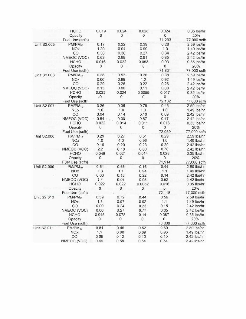
The magnitude of PM10 emissions proposed for mitigation is based on the expected average run hour profile of Eastshore for 30 years, along with the corresponding, estimated annual average PM10 emissions during the PM10 non-attainment period (i.e., October through April). The annual average PM10 emissions will be based on year 2005 source test results from a facility also equipped with 14 engines of the same model (Wärtsilä 20V34SG) as Eastshore and that are also natural gas fuel firing.
Eastshore has retained Global Energy Decisions to model the expected run hour profile of Eastshore for each month during the estimated 30 years of plant life, i.e., May 2009 through April 2039. For the estimated PM10 annual emissions proposed for mitigation, the year 2005 Western 102 (Barrick) source test results (included in this Appendix 8.1A), was reviewed. The median PM10 emission rate was approximately 0.40 lbs/hr among the 3-subtests performed for each engine. The highest average from the 3-subtests among the fourteen engines was 0.60 lb/hr. This highest tested value is used in the calculations described below.
To determine the magnitude of PM10 emissions proposed for mitigation, the annual average PM10 emissions was determined as follows:
• Monthly average operating hours over the 30-year period – The average operating hours for each month (from May 2009 through April 2039) was estimated based on the results of Global Consulting’s modeling efforts.
• Monthly PM10 emissions – The PM10 emissions for each month were estimated based on multiplying the PM10 emission value (0.60 lb/hr) by the average operating hours for each month (from May 2009 through April 2039).
• 30-year average operating hours – The average operating hours determined for each month (e.g., January, February, etc.) over the 30-year period were totaled and divided by 30. This value results in the 30-year average operating hours for a specific month. (See Table 8.1A-13.) For instance, all of the 30 May months (from years 2009 to 2039) are summed-up and then divided by 30.
• 30-year average PM10 emissions – The average projected operating hours for a given month as determined by Global’s model was multiplied by the highest as-tested Western 102 emission rate (e.g. 0.60 lb/hr), then multiplied again by 14 (to account for all 14 engines), and then divided by 2,000 to obtain operating tonnage for the month. This process was repeated for all months for 30 years. The 30 values for a given month were then averaged.
• 300 cold starts and PM10 emissions – Because the vast majority of expected operating days from the results of the Global model only started the engines one time, and further, because the downtime between starts predicted by the model was sufficient to remove the engines’ catalyst systems from being in a “warm” condition, all start-ups were assumed to be cold. 300 cold starts/engine were added on to the total emissions described in the prior bullet on a pro rata basis.

The pro rata cold starts multiplier used for any given month was the ratio of that month’s projected 30-year average operating hours divided by the 30-year total annual operating hours. This ratio was multiplied by 300, and then by the cold start emission quantity for an engine, and then by 14 (to account for all 14 engines), and then divided by 2,000.
• The sum of the 30-year average PM10 emissions and the 300 cold starts PM10 for a given month yielded the 30-year total average PM10 tons by month; the results for all months are shown in Table 8.1A-13.
• PM10 mitigation for the nonattainment period – The PM10 nonattainment period is from October through April. The sum total of October through April from the 30-year average PM10 emissions is proposed as the magnitude of PM10 emissions to be mitigated.
Eastshore presents information in Table 8.1A-13 that summarizes the results of the listed items above, i.e., 30-year average operating hours, 30-year total average PM10 emissions, and proposed PM10 mitigation. Based on this data and actual operating emissions data from Western 102 (Barrick), a facility equipped with the same engine model as Eastshore. Eastshore proposes to mitigate 6.38 tons of PM10/2.5.
TABLE 8.1A-13 Expected Average Annual Operating Hours (30-year period)1 and Annual PM10 Emissions for Mitigation
Month
30-year
Average Operating Hours
30-year Total Average PM10 Emissions,
Tons per Month2, 3
January 110.2 0.79
February 106.4 0.76
March 93.0 0.66
April 91.1 0.65
May 110.7 0.79
June 142.8 1.02
July 186.5 1.33
August 205.5 1.47
September 198.5 1.42
October 174.5 1.24
November 155.1 1.11
December 165.2 1.18
Total Annual Average 1,739 12.40
Total October-April4 895 6.38 1 30-year period from May 2009 through April 2039. 2 PM10 monthly tons include 300 cold start-ups. 3 The annual black start diesel engine PM10 emission value is 1.59E-03 tons. (See Table 8.1A-9) 4 PM10 nonattainment period in the Bay Area AQMD.

The magnitude of SO2 emissions proposed for mitigation is based on the above 30-year annual average hours of operation of 1,739. Given the full load, hourly SO2 emissions of 0.23 lb/hr per engine (Table 8.1A-5), 2.80 tons of SO2 will be mitigated. The calculation methodology is as follows:
(0.23 lb/hr SO2 per engine) * (1,739 hrs/yr) * (ton/2,000 lbs) * 14 engines = 2.80 tons/yr
(The annual black start diesel engine SO2 emission value is 5.77E-05 tons.)


®DIESEL GENERATOR SET
PRIME225 ekW 281 kVA60 Hz 1800 rpm 480 VoltsCaterpillar is leading the power generationmarketplace with Power Solutions engineeredto deliver unmatched flexibility, expandability,reliability, and cost-effectiveness.
Image shown may notreflect actual package.
FEATURES
FUEL/EMISSIONS STRATEGY• Tier 3
WORLDWIDE PRODUCT SUPPORT• Caterpillar® dealers provide extensive post sale
support including maintenance and repairagreements
• Caterpillar dealers fill 99.7% of parts orders within24 hours
• Caterpillar dealers have over 1,798 dealer branchstores operating in 200 countries
• The Cat® S•O•SSM program cost effectively detectsinternal engine component condition, even thepresence of unwanted fluids and combustionby-products
UL 2200• UL 2200 listed packages are available. Certain
restrictions may apply. Consult with yourCaterpillar dealer network
FULL RANGE OF ATTACHMENTS• Wide range of bolt-on system expansion
attachments, factory designed and tested
SINGLE-SOURCE SUPPLIER• Fully prototype tested with certified torsional
vibration analysis available
CAT® C9 ATAAC DIESEL ENGINE
• Utilizes ACERT™ Technology• Reliable, rugged, durable design• Field-proven in thousands of applications
worldwide• Four-stroke diesel engine combines consistent
performance and excellent fuel economy withminimum weight
• ADEM™A4 electronic engine control
CAT GENERATOR
• Matched to the performance and outputcharacteristics of Caterpillar engines
• 2/3 pitch minimizes harmonic distortion andfacilitates parallel operation
• Load adjustment module provides engine reliefupon load impact and improves load acceptanceand recovery time
• UL 1446 Recognized Class H Insulation
CAT EMCP 3 CONTROL PANELS
• Controls designed to meet individual customerneeds
• Options for power metering and protectiverelaying are available
• Options to meet UL/CSA/NFPA• Rear mounted power center provides convenient
location for control panel, optional powerterminal strips and optional circuit breakers

®
PRIME 225 ekW 281 kVA60 Hz 1800 rpm 480 Volts
FACTORY INSTALLED STANDARD & OPTIONAL EQUIPMENT
System Standard OptionalAir Inlet • Light Duty Air filter • Dual element & heavy duty air cleaners
Cooling • Radiator package mounted(50°C)• Coolant level sight gauge• Coolant drain line with valve• Fan and belt guards• Caterpillar Extended Life Coolant
• Radiator duct flange
Exhaust • Dry exhaust manifold • Mufflers• Stainless steel exhaust flex with split cuff connectors• Elbows
Fuel • Primary fuel filter with integral water separtor• Secondary fuel filters• Fuel cooler• Fuel priming pump• Fuel pressure gauge• Engine fuel transfer pump
• Integral UL listed fuel tank bases• Flex fuel line• Fuel level switch
Generator • Self excited• Class H insulation• Class H Temperature Rise• Random Wound• R448 voltage regulator with load adjustment module• IP23 Protection• Power Center• Single phase sensing
• Permanent magnet excitation• AREP Excitation• Oversize and premium generators• Three phase sensing• Digital voltage regulator with KVAR/PF control• Anti-condensation space heaters• Cable access box• Reactive droop
Power Termination • Bus-bar connection inside generator (NEMA pattern) • Circuit breakers, UL listed, 3 pole• Circuit breakers, IEC compliant, 3-4 pole• Power terminal strip connections in power center• Shunt trip• Auxiliary contacts
Governor • ADEM™A4 • Load share module
Control Panels • EMCP 3.1 (mounted inside power center)• Rear facing• Speed adjust• Emergency stop pushbutton• Voltage adjustment
• EMCP 3.2 & EMCP 3.3• Right-hand mounting of control panel• Local annuniciator modules (NFPA 99/110)• Remote annunicator modules (NFPA 99/110)• Discrete I/O module
Lube • Lubricating oil and filter• Oil drain line with valves• Fumes disposal• Lube oil level indicator
• Oil temperature sensor• Manual sump pump
Mounting • Formed steel wide base frame• Linear vibration isolation-seismic zone 4
• Oil field skid base• Formed steel wide base frame
Starting/Charging • 24 volt starting motor• 45 amp charging alternator
• Jacket water heater with shut off valves• Block heater• Ether starting aids• Battery disconnect switch• Battery charger(5A,10A)• Oversize batteries• Batteries with rack and cables
General • Paint - Caterpillar yellow except rails and radiatorsgloss black
• Flywheel and flywheel housing - SAE No.1
• UL 2200 packages
18 April 2006 1:21 PM2

®
PRIME 225 ekW 281 kVA60 Hz 1800 rpm 480 Volts
SPECIFICATIONS
CAT GENERATOR
Frame size................................................................ LC5014HExcitation.............................................................Self ExcitedPitch.............................................................................. 0.6667Number of poles...................................................................4Number of bearings............................................................. 1Number of leads................................................................. 12Insulation....................... UL 1446 Recognized Class H withtropicalization and antiabrasion- Consult your Caterpillar dealer for available voltagesIP rating............................................................................ IP23Alignment.............................................................. Pilot ShaftOverspeed capability...................................... 125% of ratedWave form deviation (Line to Line)................................. 2%Voltage regulator................................Single phase sensingVoltage Regulation..Less than +/- 1/2% (steady state)Lessthan +/- 1% (no load to full load)Telephone Influence Factor.............................. Less than 50Harmonic distortion......................................... Less than 5%
CAT DIESEL ENGINE
C9 ATAAC, l-6, 4-stroke-cycle watercooled dieselBore - mm.............................................. 112.00 mm (4.41 in)Stroke - mm........................................... 149.00 mm (5.87 in)Displacement - L....................................... 8.80 L (537.01 in3)Compression ratio........................................................ 16.1:1Aspiration.................. Turbocharged Air-to-Air AftercooledFuel system.................................................................... HUEIGovernor type................. Caterpillar ADEM control system
CAT EMCP 3 CONTROL PANELS
• EMCP 3.1 (Standard)• 24 Volt DC Control• NEMA 1, IP22 enclosure• UL/CSA/CE• Single location customer connector point• Run/Auto/Stop control• True RMS metering, 3-phase• Speed Adjust• Vandel cover (option)• Voltage adjust• Digital Indication for:- RPM- Operating hours- Oil Pressure- Coolant temperature- System DC volts- L-L volts, L-N volts, phase amps, Hz- ekW, kVA, kVAR,kW-hr, %kW, PF,(EMCP3.2/3.3)• Shutdowns with common indicating light for:- Low oil pressure- High coolant temperature- Low coolant level
- Overspeed- Emergency stop- Failure to start (overcrank)• Programmable protective relaying functions: (EMCP 3.2& 3.3)-Under and over voltage-Under and over frequency- Reverse power- Overcurrent• MODUS isolated data link (RS-485 half-duplex EMCP 3.2& 3.3)- Terminal box mountedConsult your Caterpillar dealer for available voltages.
18 April 2006 1:21 PM3
®
PRIME 225 ekW 281 kVA60 Hz 1800 rpm 480 Volts
TECHNICAL DATA
Open Generator Set - - 1800 rpm/60 Hz/480 Volts DM8505Tier 3
Generator Set Package PerformanceGenset Power rating @ 0.8 pfGenset Power rating with fan
281.25 kVA225 ekW
Fuel Consumption100% load with fan75% load with fan50% load with fan
68.8 L/hr 18.2 Gal/hr55.7 L/hr 14.7 Gal/hr42.0 L/hr 11.1 Gal/hr
Cooling System1
Ambient air temperatureAir flow restriction (system)Air flow (max @ rated speed for radiator arrangement)Engine coolant capacity
51 ° C 124 ° F0.12 kPa 0.48 in. water497 m³/min 17551 cfm22.0 L 5.8 gal
Exhaust SystemCombustion air inlet flow rateExhaust stack gas temperatureExhaust gas flow rateExhaust flange size (internal diameter)Exhaust system backpressure (maximum allowable)
23.8 m³/min 840.5 cfm462.0 ° C 863.6 ° F61.1 m³/min 2157.7 cfm170 mm 7 in5.9 kPa 23.7 in. water
Heat RejectionHeat rejection to coolant (total)Heat rejection to exhaust (total)Heat rejection to atmosphere from engineHeat rejection to atmosphere from generator
99 kW 5630 Btu/min257 kW 14616 Btu/min33 kW 1877 Btu/min17.2 kW 978.2 Btu/min
Alternator2
Motor starting capability @ 30% voltage dipFrameTemperature Rise
543 skVALC5014H105 ° C 221 ° F
Lube SystemSump refill with filter 40.0 L 10.6 gal
Emissions (Nominal)3
NOx g/hp-hrCO g/hp-hrHC g/hp-hrPM g/hp-hr
2.69 g/hp-hr.32 g/hp-hr.11 g/hp-hr.159 g/hp-hr
1 Ambient capability at 300m (984 ft) above sea level. For ambient capability at other altitudes, consult your Caterpillar dealer. Air flowrestriction (system) is added to existing restriction from factory. Generator temperature rise is based on a 40 C (104 F) ambient per NEMAMG1-322 Generator temperature rise is based on a 40° C (104° F) ambient per NEMA MG1-32.3 Emissions data measurement procedures are consistent with those described in EPA CFR 40 Part 89, Subpart D & E and ISO8178-1 formeasuring HC, CO, PM, NOx. Data shown is based on steady state operating conditions of 77°F, 28.42 in HG and number 2 diesel fuelwith 35° API and LHV of 18,390 btu/lb. The nominal emissions data shown is subject to instrumentation, measurement, facility andengine to engine variations. Emissions data is based on 100% load and thus cannot be used to compare to EPA regulations which usevalues based on a weighted cycle.
18 April 2006 1:21 PM4

®
PRIME 225 ekW 281 kVA60 Hz 1800 rpm 480 Volts
RATING DEFINITIONS AND CONDITIONS
Meets or Exceeds International Specifications: AS1359,AS2789, CSA, EGSA101P, IEC60034,ISO3046,ISO8528,NEMA MG 1-32, UL508, 72/23/EEC, 89/336/EEC, 98/37/EECPrime - Output available with varying load for anunlimited time. Prime power in accordance with ISO8528.10% overload power in accordance with ISO3046,AS2789, and available on request. Prime power ambientsshown indicate ambient at 100 percent load which resultsin a coolant top tank temperature just below the alarmtemperature.
Ratings are based on SAE J1995 standard conditions.These ratings also apply at ISO3046,standard conditions.Fuel rates are based on fuel oil of 35º API [16º C (60º F)]gravity having an LHV of 42 780 kJ/kg (18,390 Btu/lb)when used at 29º C (85º F) and weighing 838.9 g/liter(7.001 lbs/U.S. gal.). Additional ratings may be availablefor specific customer requirements. Consult yourCaterpillar representative for details.
18 April 2006 1:21 PM5

®
PRIME 225 ekW 281 kVA60 Hz 1800 rpm 480 Volts
DIMENSIONS
Package DimensionsLength 3132.0 mm 123.31 inWidth 1112.3 mm 43.79 inHeight 1844.5 mm 72.62 inWeight 2223 kg 4,901 lb
Note: Do not use for installation design.See general dimension drawings fordetail (Drawing #2778059).
www.CAT-ElectricPower.com
© 2006 CaterpillarAll rights reserved.
Materials and specifications are subject to change without notice.The International System of Units (SI) is used in this publication.
CAT, CATERPILLAR, their respective logos and "Caterpillar Yellow," aswell as corporate and product identity used herein, are trademarks of
Caterpillar and may not be used without permission.
6758178
Performance No.: DM8505
Feature Code:: C09DE02
Source:: U.S. Sourced
18 April 2006
6
MSDS SUMMARY SHEET
Manufacturer: Name: PHILLIPS PETROLEUM COMPANY Address 1: Address 2: Address 3: CSZ: BARTLESVILLE State: OK Zipcode: 74004 Emergency phone: (800) 424-9300 Business phone: 800-762-0942 Product: Ferndale MSDS#: 1354 Version # : 6 Manufacturer MSDS#: 0041 Current? : 2002 Name: NO. 2 DIESEL FUEL Synonyms: CARB Diesel TF3 CARB Diesel CARB Diesel 10% Diesel Fuel Oil EPA Low Sulfur Diesel Fuel EPA Low Sulfur Diesel Fuel – Dyed EPA Off Road High Sulfur Diesel – Dyed Fuel Oil No. 2 – CAS # 68476-30-2 No. 2 Diesel Fuel Oil No. 2 Fuel Oil – Non Hiway – Dyed No. 2 High Sulfur Diesel – Dyed No. 2 Low Sulfur Diesel - Dyed No. 2 Low Sulfur Diesel - Undyed Crude column 3rd IR Crude column 3rd side cut Atmospheric tower 3rd side cut Ultra Low Sulfur Diesel No. 2 Finished Diesel DHT Reactor Feed Straight Run Diesel Diesel Middle Distillate Product/Catalog Numbers: MSDS Date: 01/01/2002 (received: 01/14/2002) NFPA codes: Health: 0 Flammability: 2 Reactivity: 0

No. 2 Diesel Fuel (MSDS #0041) Page 2 of 9
MATERIAL SAFETY DATA SHEET No. 2 Diesel Fuel
1. PRODUCT AND COMPANY IDENTIFICATION Product Name: No. 2 Diesel Fuel Product Code: Multiple SAP Code: Synonyms: 1354 CARB Diesel TF3 CARB Diesel CARB Diesel 10% Diesel Fuel Oil EPA Low Sulfur Diesel Fuel EPA Low Sulfur Diesel Fuel – Dyed EPA Off Road High Sulfur Diesel – Dyed Fuel Oil No. 2 – CAS # 68476-30-2 No. 2 Diesel Fuel Oil No. 2 Fuel Oil – Non Hiway – Dyed No. 2 High Sulfur Diesel – Dyed No. 2 Low Sulfur Diesel - Dyed No. 2 Low Sulfur Diesel – Undyed No. 2 Ultra Low Sulfur Diesel – Dyed No. 2 Ultra Low Sulfur Diesel - Undyed Intended Use: Fuel Chemical Family: Responsible Party: Phillip’s Petroleum Company Bartlesville, Oklahoma 74004 For Additional MSDSs: 800-762-0942 Technical Information: The intended use of this product is indicated above. If any additional use is known, please contact us at the Technical Information number listed.
EMERGENCY OVERVIEW 24 Hour Emergency Telephone Numbers: Spill, Leak, Fire or Accident California Poison Control System: 800-356-3120 Call CHEMTREC North America: (800) 424-9300 Others: (703) 527-3887 (collect) Health Hazards/Precautionary Measures: Causes severe skin irritation. Aspiration hazard if swallowed. Can enter lungs and cause damage. Use with adequate ventilation. Avoid contact with eyes, skin and clothing. Do not taste or swallow. Wash thoroughly after handling. Physical Hazards/Precautionary Measures: Flammable liquid and vapor. Keep away from heat, sparks, flames, static electricity or other sources of ignition. Appearance: Straw-colored to dyed red Physical Form: Liquid Odor: Characteristic petroleum

No. 2 Diesel Fuel (MSDS #0041) Page 3 of 9 HFPA Hazard Class: HMIS Hazard Class Health: 0 (Least) Not Evaluated Flammability: 2 (Moderate) Reactivity: 0 (Least) 2. COMPOSITION/INFORMATION ON INGREDIENTS HAZARDOUS COMPONENTS % VOLUME EXPOSURE GUIDELINE Limits Agency Type Diesel Fuel No. 2 100 100* mg/m3 ACGIH TWA-SKIN CAS# 68476-34-6 Naphthalene <1 10ppm ACGIH TWA CAS# 91-20-3 15ppm ACGIH STEL 10ppm OSHA TWA 250ppm NIOSH IDLH All components are listed on the TSCA inventory Tosco Low Sulfur No. 2 Diesel meets the specifications of 40 CFR 60.41 for low sulfur diesel fuel. Note: State, local or other agencies or advisory groups may have established more stringent limits. Consult an industrial hygienist or similar professional, or your local agencies, for further information. *Proposed ACGIH (1999) 3. HAZARDS IDENTIFICATION Potential Health Effects: Eye: Contact may cause mild eye irritation including stinging, watering, and redness. Skin: Severe skin irritant. Contact may cause redness, itching, burning, and severe skin damage. Prolonged or repeated contact can worsen irritation by causing drying and cracking of the skin, leading to dermatitis (inflammation). Not actually toxic by skin absorption, but prolonged or repeated skin contact may be harmful (see Section 11). Inhalation (Breathing): No information available. Studies by other exposure routes suggest a low degree of toxicity by inhalation. Ingestion (Swallowing): Low degree of toxicity by ingestion. ASPIRATION HAZARD – This material can enter lungs during swallowing or vomiting and cause lung inflammation and damage. Signs and Symptoms: Effects of overexposure may include irritation of the nose and throat, irritation of the digestive tract, nausea, diarrhea and transient excitation followed by signs of nervous system depression (e.g., headache, drowsiness, dizziness, loss of coordination, disorientation and fatigue). Cancer: Possible skin cancer hazard (see Sections 11 and 14). Target Organs: There is limited evidence from animal studies that overexposure may cause injury to the kidney (see Section 11). Developmental: Inadequate data available for this material. Pre-Existing Medical Conditions: Conditions aggravated by exposure may include skin disorders and kidney disorders.
No. 2 Diesel Fuel (MSDS #0041) Page 4 of 9 4. FIRST AID MEASURES Eye: If irritation or redness develops, move victim away from exposure and into fresh air. Flush eyes with clean
water. If symptoms persist, seek medical attention. Skin: Immediately remove contaminated shoes, clothing, and constrictive jewelry and flush affected area(s) with
large amounts of water. If skin surface is damaged, apply a clean dressing and seek immediate medical attention. If skin surface is not damaged, cleanse affected area(s) thoroughly by washing with mild soap and water. If irritation or redness develops, seek immediate medical attention.
Inhalation (Breathing): If respiratory symptoms develop, move victim away from source of exposure and into fresh air. If symptoms persist, seek medical attention. If victim is not breathing, clear airway and immediately begin artificial respiration. If breathing difficulties develop, oxygen should be administered by qualified personnel. Seek immediate medical attention.
Ingestion (Swallowing): Aspiration hazard; Do not induce vomiting or give anything by mouth because this
material can enter the lungs and cause severe lung damage. If victim is drowsy or unconscious and vomiting, place on the left side with the head down. If possible, do not leave victim unattended and observe closely for adequacy of breathing. Seek medical attention.
5. FIRE FIGHTING MEASURES Flammable Properties: Flash Point: >125°F/>52° OSHA Flammability Class: Combustible liquid LEL %: 0.3 / UEL %; 10.0 Autoignition Temperature: 500°F/260°C Unusual Fire & Explosion Hazards: This material is flammable and can be ignited by heat, sparks, flames, or
other sources of ignition (e.g., static electricity, pilot lights, or mechanical/electrical equipment, and electronic devices such as cell phones, computers, calculators, and pagers which have not been certified as intrinsically safe). Vapors may travel considerable distances to a source of ignition where they can ignite, flash back, or explode. May create vapor/air explosion hazard indoors, in confined spaces, outdoors, or in sewers. Vapors are heavier than air and can accumulate in low areas. If container is not properly cooled, it can rupture in the heat of a fire.
Extinguishing Media: Dry chemical, carbon dioxide, or foam is recommended. Water spray is recommended to
cool or protect exposed materials or structures. Carbon dioxide can displace oxygen. Use caution when applying carbon dioxide in confined spaces. Water may be ineffective for extinguishment, unless used under favorable conditions by experienced fire fighters.
Fire Fighting Instructions: For fires beyond the incipient stage, emergency responders in the immediate hazard
area should wear bunker gear. When the potential chemical hazard is unknown, in enclosed or confined spaces, or when explicitly required by DOT, a self contained breathing apparatus should be worn. In addition, wear other appropriate protective equipment as conditions warrant (see Section 8).
Isolate immediate hazard area, keep unauthorized personnel out. Stop spill/release if it can be done with minimal risk. Move undamaged containers from immediate hazard area if it can be done with minimal risk.
Water spray may be useful in minimizing or dispersing vapors and to protect personnel. Cool equipment exposed to fire with water, if it can be done with minimal risk. Avoid spreading burning liquid with water used for cooling purposes.

No. 2 Diesel Fuel (MSDS #0041) Page 5 of 9 6. ACCIDENTAL RELEASE MEASURES Flammable. Keep all sources of ignition and hot metal surfaces away from spill/release. The use of explosion-proof equipment is recommended. Stay upwind and away from spill/release. Notify persons down wind of the spill/release, isolate immediate hazard area and keep unauthorized personnel out. Stop spill/release if it can be done with minimal risk. Wear appropriate protective equipment including respiratory protection as conditions warrant (see Section 8). Prevent spilled material from entering sewers, storm drains, other unauthorized drainage systems, and natural waterways. Dike far ahead of spill for later recovery or disposal. Use foam on spills to minimize vapors (see Section 5). Spilled material may be absorbed into an appropriate material. Notify fire authorities and appropriate federal, state, and local agencies. Immediate cleanup of any spill is recommended. If spill of any amount is made into or upon navigable waters, the contiguous zone, or adjoining shorelines, notify the National Response Center (phone number 800-424-8802). 7. HANDLING AND STORAGE Handling: Open container slowly to relieve any pressure. Bond and ground all equipment when transferring from one vessel to another. Can accumulate static charge by flow or agitation. Can be ignited by static discharged. The use of explosion-proof equipment is recommended and may be required (see appropriate fire codes). Refer to NFPA-704 and/or API RP 2003 for specific bonding/grounding requirements. Do not enter confined spaces such as tanks or pits without following proper entry procedures such ASTM D-4276 and 29CFR 1910.146. The use of appropriate respiratory protection is advised when concentrations exceed any established exposure limits (see Sections 2 and 8). Do not wear contaminated clothing or shoes. Keep contaminated clothing away from sources of ignition such as sparks or open flames. Use good personal hygiene practices. High pressure injection of hydrocarbon fuels, hydraulic oils or greases under the skin may have serious consequences even though no symptoms or injury may be apparent. This can happen accidentally when using high pressure equipment such as high pressure grease guns, fuel injection apparatus or from pinhole leaks in tubing or high pressure hydraulic oil equipment. “Empty” containers retain residue and may be dangerous. Do not pressurize, cut, weld, braze, solder, drill, grind, or expose such containers to heat, flame, sparks, or other sources of ignition. They may explode and cause injury or death. “Empty” drums should be completely drained, properly bunged, and promptly shipped to the supplier or a drum reconditioner. All containers should be disposed of in an environmentally safe manner and in accordance with governmental regulations. Before working on or in tanks which contain or have contained this material, refer to OSHA regulations, ANSIZ49.1 and other references pertaining to cleaning, repairing, welding, or other contemplated operations. Storage: Keep container(s) tightly closed. Use and store this material in cool, dry, well-ventilated areas away from heat, direct sunlight, hot metal surfaces, and all sources of ignition. Post area “No Smoking or Open Flame.” Store only in approved containers. Keep away from incompatible material (see Section 10). Protect container(s) against physical damage. Outdoor or detached storage is preferred. Indoor storage should meet OSHA standards and appropriate fire codes. 8. EXPOSURE CONTROLS/PERSONAL PROTECTION Engineering controls: If current ventilation practices are not adequate to maintain airborne concentration below the established exposure limits (see Section 2), additional ventilation or exhaust systems may be required. Where explosive mixtures may be present, electrical systems safe for such locations must be used (see appropriate electrical codes).

No. 2 Diesel Fuel (MSDS #0041) Page 6 of 9 Personal Protective Equipment (PPE):
Respiratory: A NIOSH certified air purifying respirator with an organic vapor cartridge maybe used under conditions where airborne concentrations are expected to exceed exposure limits (see Section 2).
Protection provided by air purifying respirators is limited (see manufacturer’s respirator selection guide). Use a positive pressure air supplied respirator if there is a potential for an uncontrolled release, exposure levels are not known, or any other circumstances where air purifying respirators may not provide adequate protection.
A respiratory protection program that meets OSHA’s 29 CFR 1910.134 and ANSI Z88.2 requirements must be followed whenever workplace conditions warrants a respirator’s use.
Skin: The use of gloves impervious to the specific material handled is advised to prevent skin contact, possible
irritation and skin damage (see glove manufacturer literature for information on permeability). Depending on conditions of use, apron and/or arm covers may be necessary.
Eyes/Face: Approved eye protection to safeguard against potential eye contact, irritation, or injury is
recommended. Depending on conditions of use, a face shield may be necessary. Other Protective Equipment: Eye wash and quick-drench shower facilities should be available in the work area.
Thoroughly clean shoes and wash contaminated clothing before reuse. It is recommended that impervious clothing be worn when skin contact is possible.
9. PHYSICAL AND CHEMICAL PROPERTIES Note: Unless otherwise stated, values are determined at 20°C (68°F) and 760 mm Hg (1atm). Appearance: Straw-colored to dyed red Physical State: Liquid Odor: Characteristic petroleum pH: unavailable Vapor Pressure (mm Hg): 0.40 Vapor Densisty (air=1):>3 Boiling Point/Range: 320-700°F /160-371°C Freezing/Melting Point: No Data Solubility in Water: Negligible Specific Gravity: 0.81-0.88 @ 60°F Percent Volatile: Negligible Evaporation Rate (nBuAc=1): <1 Viscosity: 32.6-40.0 SUS @ 100°F Bulk Density: 7.08 lbs/gal Flash Point: >125°F / >52°C Flammable/Expolsive Limits (%): LEL: 0.3 / UEL: 10.0 10. STABILITY AND REACTIVITY Stability: Stable under normal ambient and anticipated storage and handling conditions of temperature and pressure.
Flammable liquid and vapor. Vapor can cause flash fire. Conditions To Avoid: Avoid all possible sources of ignition (see Sections 5 and 7). Materials to Avoid (Incompatible Materials): Avoid contact with strong oxidants such as liquid chlorine,
concentrated oxygen, sodium hypochlorite, calcium hypochlorite, etc.

No. 2 Diesel Fuel (MSDS #0041) Page 7 of 9 Hazardous Decomposition Products: The use of hydrocarbon fuels in an area without adequate ventilation may
result in hazardous levels of combustion products (e.g., oxides of carbon, sulfur and nitrogen, benzene and other hydrocarbons) and/or dangerously low oxygen levels. ACGIH has included a TLV of 0.05 mg/m3 TWA for diesel exhaust particulate on its 1999 Notice of Intended Changes. See Section 11 for additional information on hazards of engine exhaust.
Hazardous Polymerization: Will not occur. 11. TOXICOLOGICAL INFORMATION Diesel Fuel No. 2 (CAS# 68476-34-6) Carcinogenicity: Chronic dermal application of certain middle distillate streams contained in diesel fuel No. 2 resulted in an increased incidence of skin tumors in mice. This material has not been identified as carcinogen by NTP, IARC, or OSHA. Diesel exhaust is a probable cancer hazard based on tests with laboratory animals. Target Organ(s): Limited evidence of renal impairment has been noted from a few case reports involving excessive exposure to diesel fuel No. 2. Naphthalene (CAS# 91-20-3) Carcinogenicity: Naphthalene has been evaluated in two year inhalation studies in both rats and mice. The National Toxicology Program (NTP) concluded that there is clear evidence of carcinogenicity in male and female rats based on increased incidences of respiratory epithelial adenomas and olfactory epithelial neuroblastomas of the nose. NTP found some evidence of carcinogenicity in female mice (alveolar adenomas) and no evidence of carcinogenicity in male mice. Naphthalene has not been identified as a carcinogen by IARC or OSHA. 12. ECOLOGICAL INFORMATION Not evaluated at this time 13. DISPOSAL CONSIDERATIONS This material, if discarded as produced, would be a RCRA “characteristic” hazardous waste due to the characteristic(s) of ignitability (D001) and benzene (D018). If the material is spilled to soil or water, characteristic testing of the contaminated materials is recommended. Further, this material, once it becomes a waste, is subject to the land disposal restrictions in 40 CFR 268.40 and may require treatment prior to disposal to meet specific standards. Consult state and local regulations to determine whether they are more stringent then the federal requirements. Container contents should be completely used and containers should be emptied prior to discard. Container ?insate? could be considered a RCRA hazardous waste and must be disposed of with care and in compliance with federal, state and local regulations. Large empty containers, such as drums, should be returned to the distributor or to a drum reconditioner. To assure proper disposal of smaller containers, consult with state and local regulations and disposal authorities. 14. TRANSPORT INFORMATION DOT Shipping Description: Diesel Fuel, NA1983 Non-Bulk Package Marking: Diesel Fuel, 3, NA 1993, III
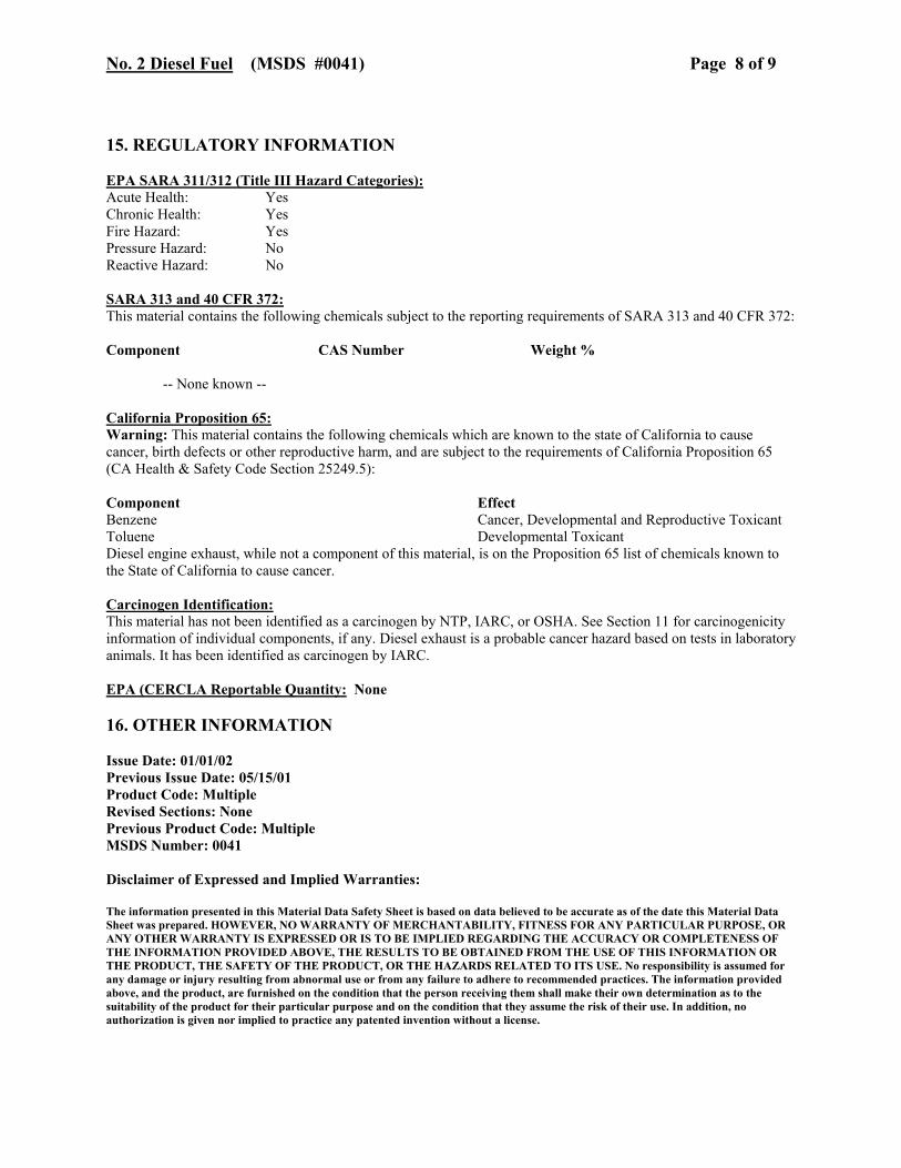
No. 2 Diesel Fuel (MSDS #0041) Page 8 of 9 15. REGULATORY INFORMATION EPA SARA 311/312 (Title III Hazard Categories): Acute Health: Yes Chronic Health: Yes Fire Hazard: Yes Pressure Hazard: No Reactive Hazard: No SARA 313 and 40 CFR 372: This material contains the following chemicals subject to the reporting requirements of SARA 313 and 40 CFR 372: Component CAS Number Weight %
-- None known --
California Proposition 65: Warning: This material contains the following chemicals which are known to the state of California to cause cancer, birth defects or other reproductive harm, and are subject to the requirements of California Proposition 65 (CA Health & Safety Code Section 25249.5): Component Effect Benzene Cancer, Developmental and Reproductive Toxicant Toluene Developmental Toxicant Diesel engine exhaust, while not a component of this material, is on the Proposition 65 list of chemicals known to the State of California to cause cancer. Carcinogen Identification: This material has not been identified as a carcinogen by NTP, IARC, or OSHA. See Section 11 for carcinogenicity information of individual components, if any. Diesel exhaust is a probable cancer hazard based on tests in laboratory animals. It has been identified as carcinogen by IARC. EPA (CERCLA Reportable Quantity: None 16. OTHER INFORMATION Issue Date: 01/01/02 Previous Issue Date: 05/15/01 Product Code: Multiple Revised Sections: None Previous Product Code: Multiple MSDS Number: 0041 Disclaimer of Expressed and Implied Warranties: The information presented in this Material Data Safety Sheet is based on data believed to be accurate as of the date this Material Data Sheet was prepared. HOWEVER, NO WARRANTY OF MERCHANTABILITY, FITNESS FOR ANY PARTICULAR PURPOSE, OR ANY OTHER WARRANTY IS EXPRESSED OR IS TO BE IMPLIED REGARDING THE ACCURACY OR COMPLETENESS OF THE INFORMATION PROVIDED ABOVE, THE RESULTS TO BE OBTAINED FROM THE USE OF THIS INFORMATION OR THE PRODUCT, THE SAFETY OF THE PRODUCT, OR THE HAZARDS RELATED TO ITS USE. No responsibility is assumed for any damage or injury resulting from abnormal use or from any failure to adhere to recommended practices. The information provided above, and the product, are furnished on the condition that the person receiving them shall make their own determination as to the suitability of the product for their particular purpose and on the condition that they assume the risk of their use. In addition, no authorization is given nor implied to practice any patented invention without a license.

No. 2 Diesel Fuel (MSDS #0041) Page 9 of 9 Tosco Refining Company Ferndale Refinery
UltraLow Sulfur Diesel Product Specification Ferndale Product Code:34380xx (5) Product Code: ULSD2 (COMETS) Specification Unit Limit Test Procedure Typical Appearance Water & Sediment Color Haze Rating
Vol % Number Rating
0.05 Max 3.0 Max 2 Max
D 2709 D 1500 D 4176
Composition Carbon Residue (Ramsbottom)
Wt %
0.35 Max
D 524, D 189
Volatility 90% Recovered Flash Point Gravity
Deg; F Deg; F Deg; F API
540 Min 640 Min 125 Min (1) 30 Min
D 86 D 86 D 93 D 287, D4052
130 F
Fluidity Pour Point Cloud Point Viscosity @ 104F Lubricity, SLBOCLE Lubricity, HFRR
Deg; F Deg; F cSt cSt grams mm
See Season Table (6) See Season Table (6) 1.9 Min 4.1 Max 3100 Min .45
D 97 D 2500 D 445 D 445 D 6078 D 6079
10 F 3300gm
Combustion Cetane Index or Cetane Number (3,4)
Number
40.0 Min
D 976, D613
47.0
Corrosion Copper Strip, 3hr @ 50 deg C
Number
3 Max (2)
D 130
Aromatics (4) Vol % 35 Max D 1319 25 % Contaminants Total Sulfur Water & Sediment Ash
PPM Vol % Wt %
30 Max 0.05 Max 0.01 Max
D 2622, D4294 D 1796 D 482
15-20ppm
Additives Cetane Improver Dye
Lb/MBbl
675 Max Undyed
1. Minimum release specification is 125 deg. F. The refinery should target 135 deg. F. 2. Test result reported as a number and letter (e.g. 1a). Any letter is allowable as long as the number meets the spec
shown. 3. Either specification must be met. 4. Either cetane index minimum or aromatics maximum must be met. 5. Winter cloud and pour specifications may be relaxed to the summer specifications by agreement with the customer. 6. Season Table
Month Product Code Pour Point Cloud Point Jan, Feb, Nov, Dec WI 0 max (5) 14 max (5) Mar - Oct SU 15 max 24 max