appendix 2-l constructability assessment report
TRANSCRIPT

Appendix 2-L
APPENDIX 2-L: CONSTRUCTABILITY ASSESSMENT REPORT - RECORD PEPD
California High-Speed Rail Authority April 2020
San Jose to Merced Project Section Draft Project EIR/EIS


California High-Speed Rail Authority
San Jose to Merced Project Section: San Jose to Central Valley Wye
Constructability Assessment Report – Record PEPD
March 2019


Table of Contents
California High‐Speed Rail Project March 2019
San Jose to Central Valley Wye Constructability Assessment Report – Record PEPD Page | i
TABLE OF CONTENTS
1 EXECUTIVE SUMMARY ........................................................................................ 1-1 1.1 Scope and Approach .................................................................................... 1-1 1.2 Conclusions and Recommendations ............................................................ 1-1
2 INTRODUCTION ..................................................................................................... 2-3 2.1 Purpose ........................................................................................................ 2-3 2.2 Project Overview .......................................................................................... 2-3 2.3 Project Description ....................................................................................... 2-4 2.4 Alignment Alternatives ..................................... Error! Bookmark not defined. 2.5 Infrastructure Improvements and Phasing .................................................... 2-9
3 SEGMENT CONSTRUCTION PACKAGING .......................................................... 3-1 3.1 Risks ............................................................................................................. 3-2 3.2 Recommendations ........................................................................................ 3-2
4 GENERAL CONSTRUCTION METHODS .............................................................. 4-1 4.1 Clearing and Grubbing ................................................................................. 4-1 4.2 Demolition ..................................................................................................... 4-1 4.3 Earthwork ..................................................................................................... 4-1 4.4 Roadway ....................................................................................................... 4-3 4.5 Drainage ....................................................................................................... 4-4 4.6 Structures ..................................................................................................... 4-5
4.6.1 Aerial Structures ............................................................................ 4-5 4.6.2 Open-Trench Excavation ............................................................. 4-14 4.6.3 Cut-and-Cover Tunnel ................................................................. 4-15 4.6.4 Bored Tunnels ............................................................................. 4-15 4.6.5 Retaining Walls ............................................................................ 4-15
4.7 Track ........................................................................................................... 4-15 4.8 Utility Relocations/Adjustments/Construction ............................................. 4-19
5 SUBSECTION CONSTRUCTION ........................................................................... 5-1 5.1 San Jose Diridon Station Approach .............................................................. 5-1
5.1.1 Alternative 1 ................................................................................... 5-1 5.1.2 Alternative 2 ................................................................................... 5-2 5.1.3 Alternative 4 ................................................................................... 5-2
5.2 Monterey Corridor ......................................................................................... 5-3 5.2.1 Monterey Corridor At-Grade/Embankment (Alternative 2) ............. 5-3 5.2.2 Monterey Corridor Viaduct (Alternative 1) ...................................... 5-4 5.2.3 Monterey Corridor Blended At-Grade (Alternative 4) ..................... 5-5
5.3 Morgan Hill and Gilroy .................................................................................. 5-6 5.3.1 Viaduct to Downtown Gilroy (Alternative 1) ................................... 5-6 5.3.2 Embankment to Downtown Gilroy (Alternative 2) .......................... 5-7 5.3.3 Viaduct to East Gilroy (Alternative 3) ............................................. 5-9 5.3.4 Blended At-Grade to Downtown Gilroy (Alternative 4) ................... 5-9
5.4 Gilroy and Pacheco Pass Tunnels (Alternatives 1-4) ................................. 5-10 5.5 San Joaquin Valley (Alternatives 1-4) ........................................................ 5-11
6 CONSTRUCTION STAGING AREAS ..................................................................... 6-1 6.1 Monterey Viaduct Alignment Using Full Span Construction ......................... 6-1
6.1.1 Location ......................................................................................... 6-1 6.1.2 Description of Site .......................................................................... 6-3
Table of Contents
6.1.3 Criteria Compliance ....................................................................... 6-36.1.4 General Size, Shape, Location...................................................... 6-36.1.5 Site Summary ................................................................................ 6-4
6.2 Blended At-Grade Alignment Construction .................................................. 6-46.2.1 Location ......................................................................................... 6-46.2.2 Description of Site ......................................................................... 6-56.2.3 Criteria Compliance ....................................................................... 6-56.2.4 General Size, Shape, Location...................................................... 6-56.2.5 Site Summary ................................................................................ 6-5
7 PRECASTING OPERATIONS AND YARD REQUIREMENTS .............................. 7-1
8 CONSTRUCTION SEQUENCING .......................................................................... 8-18.1 Construction Timing Constraints .................................................................. 8-18.2 Enabling Works ............................................................................................ 8-18.3 Typical Construction Sequencing and Durations ......................................... 8-1
9 TRAFFIC CONTROL AND DETOURS ................................................................... 9-19.1 At-Grade Crossing Replacement ................................................................. 9-19.2 Monterey Corridor Grade Separations ......................................................... 9-19.3 Caltrain Station Access ................................................................................ 9-2
10 CONSTRUCTION POLLUTION CONTROL ......................................................... 10-110.1 Air Quality................................................................................................... 10-110.2 Noise and Vibration .................................................................................... 10-1
10.2.1 Water Quality............................................................................... 10-1
11 CONSTRUCTION PERMITS ................................................................................ 11-1
12 THIRD PARTY COORDINATION AND AGREEMENTS ...................................... 12-112.1 Caltrans 12-1 12.2 Utilities 12-1 12.3 Railroads .................................................................................................... 12-2
12.3.1 Caltrain ........................................................................................ 12-212.3.2 Union Pacific Railroad ................................................................. 12-3
12.4 Local Jurisdictions ...................................................................................... 12-312.4.1 Discussion ................................................................................... 12-3
12.5 Coordinating Betterments and Adjoining Third Party Work ........................ 12-412.5.1 Discussion ................................................................................... 12-4
13 POTENTIAL EXCAVATION HAZARDS................................................................ 13-113.1 Surface Soils .............................................................................................. 13-113.2 Deep Excavations ...................................................................................... 13-1
14 RIGHT-OF-WAY ACQUISITION........................................................................... 14-1
15 CONSTRUCTION POLLUTION CONTROL ......................................................... 15-1
16 CONCLUSIONS.................................................................................................... 16-1
17 REFERENCES ..................................................................................................... 17-1
March 2019 California High‐Speed Rail Project
ii | Page San Jose to Central Valley Wye Constructability Assessment Report – Record PEPD

Table of Contents
Tables
Table 2-1 San Jose to Central Valley Wye Design Options by Subsection ...................2-7
Table 5-1 San Jose to Merced HSR Project Subsections ............................................ 5-10
Table 11-1 Construction Permits .................................................................................. 11-1
Figures
Figure 2-1 High-Speed Rail System in California........................................................... 2-4
Figure 2-2 San Jose to Central Valley Wye Project Map and Subsections....................2-5
Figure 4-1 Expected Haul Distances from Various Types of Equipment .......................4-2
Figure 4-2 Precast Full Span Construction Schematic ..................................................4-5
Figure 4-3 Taiwan High Speed Rail (Courtesy of Uwe Baier) ........................................4-6
Figure 4-4 Precast Full Span Sequence and Production Rate ...................................... 4-7
Figure 4-5 Precast Segmental Construction Schematic................................................. 4-8
Figure 4-6 Precast Segmental Construction .................................................................. 4-9
Figure 4-7 Precast Segmental Sequence and Production Rate ...................................4-10
Figure 4-8 Balanced Cantilever Construction Components ......................................... 4-11
Figure 4-9 Form Travelers and Temporary Supports in Balanced Cantilever Construction ........................................................................................................... 4-11
Figure 4-10 Balanced Cantilever Sequence and Production Rate ............................... 4-12
Figure 4-11 Traveling Formwork System from HSR Tech Memo TM 2.3.3 .................4-13
Figure 4-12 CIP Concrete Construction Sequence and Production Rate ....................4-14
Figure 4-13 Ballast Track - Schotteroberbau ............................................................... 4-16
Figure 4-14 Ballast Track with Mats - Japan................................................................ 4-16
Figure 4-15 Ballast Track Turnouts .............................................................................. 4-16
Figure 4-16 Slab Track - China HSR ........................................................................... 4-17
Figure 4-17 Track Turnouts - China HSR..................................................................... 4-17
Figure 5-1 Typical Section in Subsection San Jose Diridon Station Alternative 1 .........5-1
Figure 5-2 Typical Section in Subsection San Jose Diridon Station Alternative 2 .........5-2
Figure 5-3 Typical Sections in Subsection Pacheco Pass (Tunnel).............................5-11
Figure 6-1 Far North End Staging Area, Alternatives 1 and 3 (Sta 310+00 near Capitol Caltrain)........................................................................................................ 6-1
Figure 6-2 Central Staging Area, Alternatives 1 and 3 (Sta 920+00 near Morgan Hill) ........................................................................................................................... 6-2
Figure 6-3 South End Staging Area, Alternative 1 (Sta 1575+00 in Gilroy) ..................6-2
Figure 6-44South End Staging Area, Alternative 3 (Sta 1605+00 in Gilroy) .................6-3
Figure 7-1 Precast Yard Layout ..................................................................................... 7-1
California High‐Speed Rail Project March 2019
San Jose to Central Valley Wye Constructability Assessment Report – Record PEPD Page | iii

Table of Contents
Appendices
Appendix A: Monterey Highway Viaduct, Typical Section Installation – Full Span Precast
Appendix B: Monterey Highway Viaduct, Balanced Cantilever Installation
Appendix C: Monterey Highway Viaduct, Precast Box Girder Yard Dimensions
Appendix D: San Jose Station Approach Constructability Analysis
Appendix E: Potential Contract Packages and Schedule
Appendix F: Potential Construction Sequence at I-280
Appendix G: Potential Construction Sequence at Monterey Highway
Appendix H: Track Shift Works
March 2019 California High‐Speed Rail Project
iv | Page San Jose to Central Valley Wye Constructability Assessment Report – Record PEPD

Acronyms and Abbreviations
California High‐Speed Rail Project March 2019
San Jose to Central Valley Wye Constructability Assessment Report – Record PEPD Page | v
ACRONYMS AND ABBREVIATIONS
AB (California) Assembly Bill
ATC Automatic Train Control
Authority California High-Speed Rail Authority
BC Balanced Cantilever
BMP best management practice
C&M Construction & Maintenance
CalMod Caltrain Modernization
Caltrans California Department of Transportation
CAMUTCD California Manual on Uniform Traffic Control Devices
CEQA California Environmental Quality Act
C.F.R. Code of Federal Regulations
CHSR California High-Speed Rail
CIDH cast-in-drilled hole
CIP cast-in place
CVY Central Valley Wye
EIR Environmental Impact Report
EIS Environmental Impact Statement
FHWA Federal Highway Administration
FRA Federal Railroad Administration
FTA Federal Transit Administration
HSR high-speed rail
JM San Jose to Merced Project Section
MOU Memorandum of Understanding
MOWF Maintenance of Way Facility
MOWS Maintenance of Way Siding
NEPA National Environmental Policy Act
NPDES National Pollutant Discharge Elimination System
OCS Overhead Contact System
PCEP Caltrain Peninsula Corridor Electrification Project,
PCJPB Peninsula Corridor Joint Powers Board
PEPD Preliminary Engineering for Project Definition
RC Regional Consultant
ROW right-of-way
RWQCB Regional Water Quality Control Board

Acronyms and Abbreviations
March 2019 California High‐Speed Rail Project
vi | Page San Jose to Central Valley Wye Constructability Assessment Report – Record PEPD
SR State Route
SWPPP Stormwater Pollution Prevention Plan
UPRR Union Pacific Railroad
VdB vibration decibels
VTA Santa Clara Valley Transportation Authority

Section 1 Executive Summary
California High‐Speed Rail Project March 2019
San Jose to Central Valley Wye Constructability Assessment Report – Record PEPD Page | 1‐1
1 EXECUTIVE SUMMARY
1.1 Scope and Approach
HNTB studied constructability of the San Jose to Merced (JM) Section of the California High-Speed Rail (CHSR) project. Information used included preliminary designs with plans, profiles and cross-sections at the Draft Project Engineering for Project Definition (PEPD) submittal stage.
We approached the study with a mission to understand the project and provide feedback on concerns that a construction contractor or manager might have. We identified numerous factors that could challenge designers, contractors, and agency construction managers. We have provided discussion, a set of risks, and recommendations for action or further study.
1.2 Conclusions and Recommendations
We have concluded that each of the four alternatives, as currently presented, can be built, but they present varying degrees of complexity, cost, duration, and impact on the environment and the public. Physical and other constraints of each alternative will vary the expense, duration, and impact of each one.
“Big ticket” concerns that should be addressed in detail before the project is built include:
Property acquisition will be long and complex. The California High-Speed Rail Authority (Authority) should carry out property acquisitions itself and not delegate this to the design-build contractors.
Construction work on route segments should not be started before all property acquisitions are made for the segment.
Responsibility, processes, and payment mechanisms for dealing with unforeseen environmental contamination should be established in construction contract documents.
Construction and maintenance (C&M) agreements with stakeholders, including local jurisdictions, California Department of Transportation (Caltrans), and utilities should be comprehensive, detailed, and executed before beginning construction.
Reflect stakeholder agreements in the construction contract documents, and bind contractors to perform in accordance with the stakeholder agreements.
Accommodation of Caltrain and Union Pacific Railroad (UPRR) train operations will constrain construction operations and increase the construction cost and duration.
At-grade and viaduct cross-sections are the most buildable cross-sections.
Trench and embankment cross-sections present the most difficult staging challenges, mostly due to constrained right-of-way (ROW) width, earthmoving operations, and difficulties stemming from maintaining Caltrain and UPRR operations without modification.


Section 2 Introduction
California High‐Speed Rail Project March 2019
San Jose to Central Valley Wye Constructability Assessment Report – Record PEPD Page | 2‐3
2 INTRODUCTION
2.1 Purpose
The purpose of this Constructability Assessment Report is to provide a general overview of the different types of construction elements involved in this section of the project, identify potential construction concerns, and provide insight into the activities and general sequencing necessary to complete the construction.
This report is divided into various sections that each discuss a separate topic:
Section 3: Provides a general overview of the project
Section 4: Provides options and recommendations for a series of construction contract packages.
Section 5: Discusses general construction elements with probable production rate estimates.
Section 6: Provides additional insight into individual subsection construction elements, challenges, and general sequencing of construction
Section 7: Identifies staging areas.
Section 8: Provides a casting yard layout.
Section 9: Describes construction sequencing.
Section 10: Provides a general discussion on traffic control and detours for the project.
Section 11: Describes pollution control.
Section 12: Provides a list of probable construction permits that may be required.
Section 13: Discusses Third Party Coordination and Agreements.
Section 14: Describes potential excavation hazards.
Section 15: Discusses ROW acquisition.
Section 16: Discusses construction pollution control.
Section 17: Provides summary conclusions.
Section 18: References.
2.2 Project Overview
The California High-Speed Rail Authority (Authority) proposes to construct, operate, and maintain an electric-powered HSR system in California. When completed, the nearly 800-mile train system would provide new passenger rail service to more than 90 percent of the state’s population. More than 200 weekday trains would serve the statewide intercity travel market. The HSR will be capable of operating speeds of up to 220 miles per hour (mph), with state-of-the-art safety, signaling, and automated train control (ATC) systems. The system will connect and serve the state’s major metropolitan areas, extending from San Francisco to Los Angeles and Anaheim in Phase 1, with extensions to Sacramento and San Diego in Phase 2. The HSR system will be designed to be capable of a nonstop operational service time between San Francisco and Los Angeles of 2 hours and 40 minutes.
The statewide California HSR Project has been divided into a number of geographic sections for the planning, environmental approval, design, and implementation of the project. This memorandum supports the section of the HSR System between San Jose and Merced, and specifically covers the San Jose to Central Valley Wye project extent from Scott Boulevard in Santa Clara to Carlucci Road in Merced County). See Figure 2-1 Proposed San Jose to Merced Project Section.

Section 2 Introduction
March 2019 California High‐Speed Rail Project
2‐4 | Page San Jose to Central Valley Wye Constructability Assessment Report – Record PEPD
Figure 2-1 Proposed San Jose to Merced Project Section
2.3 Project Description
The San Jose to Central Valley Wye segment of the HSR corridor extends approximately 90 miles and includes portions of blended and dedicated track and systems; HSR stations located at San Jose, Diridon, and Gilroy; a maintenance of way facility (MOWF) in the Gilroy area; and a maintenance of way siding (MOWS) west of Turner Island Road in the Central Valley. The project continues south from San Jose to Gilroy, then east through the Pacheco Pass to the Central Valley and ends at Carlucci Road the western boundary of the Central Valley Wye.
The infrastructure and systems of the HSR system consist of HSR trains, tracks, stations, automatic train control (ATC) and communication sites, overhead contact system (OCS) and traction power distribution systems, and infrastructure and vehicle maintenance facilities. The design of dedicated system portions of each HSR alternative includes a double-track rail system to accommodate planned project operational needs for high-capacity rail movement. The HSR safety criteria requires avoidance of at-grade intersections on dedicated HSR alignments where operating speeds will exceed 125 mph; accordingly, the system will require grade-separated overcrossings or undercrossings for roadways that intersect the planned right-of-way. In areas where operating speeds will be less than 125 mph, at-grade intersections may be used. The HSR system will be on an access-controlled guideway with mainline tracks, maintenance, and storage facilities including intrusion detection and monitoring systems designed to prevent access by unauthorized vehicles, persons, animals, and objects. The ends of the HSR trainsets would include a collision response management system to minimize the effects of a collision.
The project comprises the following five subsections shown in Figure 2-2:
San Jose Diridon Station Approach—Extends approximately 6 miles from north of San Jose Diridon Station at Scott Boulevard in Santa Clara to West Alma Avenue in San Jose. This subsection includes the San Jose Diridon Station and overlaps the southern portion of the San Francisco to San Jose Project Section.
Monterey Corridor—Extends approximately 9 miles from West Alma Avenue to Bernal Way in the community of South San Jose. This subsection is entirely within the city of San Jose.

Section 2 Introduction
California High‐Speed Rail Project March 2019
San Jose to Central Valley Wye Constructability Assessment Report – Record PEPD Page | 2‐5
Source: Authority 2018c, 2018d
Figure 2-2 San Jose to Central Valley Wye Project Map and Subsections


Section 2 Introduction
California High‐Speed Rail Project March 2019
San Jose to Central Valley Wye Constructability Assessment Report – Record PEPD Page | 2‐7
Morgan Hill and Gilroy—Extends approximately 30–32 miles from Bernal Way in the community of South San Jose to Casa de Fruta Parkway/State Route (SR) 152 in the community of Casa de Fruta in Santa Clara County.
Pacheco Pass—Extends approximately 25 miles from Casa de Fruta Parkway/SR 152 to Interstate 5 (I-5) in Merced County.
San Joaquin Valley—Extends approximately 18 miles from I-5 to Carlucci Road in unincorporated Merced County.
2.4 Alignment Alternatives
The Authority and the Federal Railroad Administration (FRA) have developed four end-to-end alternatives for the project. Table 2-1 shows the distinguishing features of each alternative by subsection.
Table 2-1 San Jose to Central Valley Wye Design Options by Subsection
Subsection/Design Options Alternative
1 Alternative
2 Alternative
3 Alternative
4
San Jose Diridon Station Approach
Viaduct to Scott Boulevard X X
Viaduct to I-880 X
Blended, At-Grade X
Monterey Corridor
Viaduct X X
At-Grade/Embankment X
Blended, At-Grade X
Morgan Hill and Gilroy
Embankment to downtown Gilroy X
Viaduct to downtown Gilroy X
Viaduct to east Gilroy X
Blended, At-Grade to downtown Gilroy X
Pacheco Pass
Tunnel X X X X
San Joaquin Valley
Henry Miller Road X X X X Source: Authority 2018c, 2018d
For Alternatives 1, 2, and 3, HSR transitions from the blended system between San Francisco and Santa Clara to a fully dedicated double-track system north of the San Jose Diridon Station at either Scott Boulevard or near I-880. Within the dedicated system, track will either be elevated or grade separated from surface roadways so there will be no grade crossings between the high-speed train and vehicular traffic.
Alternative 4 would extend the blended system through San Jose to Gilroy and would be substantially within the existing Caltrain and UPRR rights-of-way before transitioning to a fully dedicated system. Within the blended service portions, train speed would be limited to 110 mph,

Section 2 Introduction
March 2019 California High‐Speed Rail Project
2‐8 | Page San Jose to Central Valley Wye Constructability Assessment Report – Record PEPD
and at-grade roadway crossings would be permitted with additional safety improvements. Two tracks would be provided for blended passenger service with an additional track for dedicated freight use by UPRR. Alternative 4 would utilize existing and in-progress infrastructure improvements developed by Caltrain for its Caltrain Modernization Program, including electrification of the Caltrain corridor between San Francisco and Tamien under the Caltrain Peninsula Corridor Electrification Project (PCEP), and the installation of an advanced signal system under the Communications Based Overlay Signal System (CBOSS) Positive Train Control Project south to Control Point Lick. It would also require modifications and safety and security improvements at existing Caltrain stations to accommodate HSR trains.
Alternative 1 (Morgan Hill to Downtown Gilroy Viaduct Alternative) would comprise the following alternative subsection alignments and elements (from north to south):
1. San Jose Diridon Station Approach Subsection – from Scott Boulevard to I-880, HSR travels at-grade in the blended Caltrain corridor and transitions to a dedicated aerial viaduct structure south of I-880 that connects to the San Jose Diridon Station;
2. Monterey Corridor Subsection – from West Alma south, the alignment continues on an aerial viaduct structure;
3. Morgan Hill and Gilroy Subsection – south of Kittery Court, HSR travels primarily on an aerial viaduct through the Downtown Gilroy Station, the South Gilroy MOWF, and Tunnel 1;
4. Pacheco Pass Subsection – the HSR alignment travels through a 13.5-mile-long tunnel; and
5. San Joaquin Valley Subsection - HSR transitions to an embankment at Henry Miller Road, travels through the Los Banos MOWS and connects to the Central Valley Wye HSR Section at Carlucci Road.
Alternative 2 (East UPRR/Downtown Gilroy Embankment) would include the following alternative alignments and elements:
1. San Jose Diridon Station Approach Subsection - starting at Scott Boulevard, the alignment transitions from blended service with Caltrain to a dedicated aerial viaduct that connects to San Jose Diridon Station;
2. Monterey Corridor Subsection - from West Alma south to Bernal/Kittery Court, the HSR alignment travels primarily on embankment;
3. Morgan Hill and Gilroy Subsection – south of Kittery Court, HSR travels on an embankment through the Downtown Gilroy Station and the South Gilroy MOWF through Tunnel 1 to the Pacheco Pass;
4. Pacheco Pass Subsection – is consistent with Alternative 1; and 5. San Joaquin Valley Subsection – is consistent with Alternative 1.
Alternative 3 (Morgan Hill/East Gilroy) would include the following alternative alignments and elements:
1. San Jose Diridon Station Approach Subsection – is consistent with Alternative 2, starting at Scott Boulevard, the alignment transitions from blended service with Caltrain to a dedicated aerial viaduct that connects to the San Jose Diridon Station;
2. Monterey Corridor Subsection – is consistent with Alternative 1; 3. Morgan Hill and Gilroy Subsection – south of Kittery Court, HSR continues primarily
on a viaduct through East Gilroy (including East Gilroy Station and East Gilroy MOWF) and Tunnel 1 to Pacheco Pass;
4. Pacheco Pass Subsection – is consistent with Alternative 1; and 5. San Joaquin Valley Subsection – is consistent with Alternative 1.

Section 2 Introduction
California High‐Speed Rail Project March 2019
San Jose to Central Valley Wye Constructability Assessment Report – Record PEPD Page | 2‐9
Alternative 4 (Blended At-grade) would include the following alternative alignments and elements:
1. San Jose Diridon Station Approach Subsection – starting at Scott Boulevard, the alignment remains as blended service with Caltrain to an at-grade San Jose Diridon Station and continuing along the existing Caltrain ROW to West Alma Avenue (south of the Caltrain Tamien Station);
2. Monterey Corridor Subsection – from West Alma Avenue south to Bernal/Kittery Court, the HSR alignment travels at-grade in the existing Caltrain ROW to CP Lick, then in UPRR ROW to south of Kittery Court;
3. Morgan Hill and Gilroy Subsection – south of Kittery Court, HSR travels at-grade in the existing UPRR ROW to the Downtown Gilroy Station, at which point the blended service transitions to a dedicated HSR ROW and a South Gilroy MOWF to the west of the mainline. South of the MOWF, the alignment is consistent with Alternative 1;
4. Pacheco Pass Subsection – is consistent with Alternative 1; and 5. San Joaquin Valley Subsection – is consistent with Alternative 1.
2.5 Infrastructure Improvements and Phasing
HSR blended service from Santa Clara to Gilroy will be phased per the Authority’s 2018 Business Plan. This stipulates that improvements will be phased to meet 2027 and 2033 operating requirements, as follows:
2027 Peninsula Service – San Jose to Gilroy
Convert all at-grade crossings to four quadrant gates with channelization to permit operations up to 110 mph;
Maintain current maximum allowable speed (MAS) of 79 mph;
Raise and extend two at-grade platforms at the San Jose Diridon Station for HSR use;
Between CP Coast and Diridon, provide for two electrified tracks for blended service, and two non-electrified tracks for UPRR use;
South of Diridon to Gilroy, provide for one non-electrified track (MT1), two electrified tracks (MT2 and MT3);
Reconfigure VTA/Caltrain stations at San Martin, Morgan Hill, Blossom Hill and Capitol to be accessed from MT2 and MT3; and
Reconfigure Gilroy Station with two high level platforms for HSR use and provision for HSR bypass tracks, and two low level platforms for Caltrain/TAMC
Construct the South Gilroy MOWF with access from UPRR.
Provide completely access controlled ROW using fences, trespass guards and quad-gates.
2029 Valley to Valley Service
Provide connecting tracks south from Gilroy Station to connect with dedicated HSR alignment;
2033 Phase One
Increase MAS to 110 mph between Santa Clara and Gilroy.

Section 2 Introduction
March 2019 California High‐Speed Rail Project
2‐10 | Page San Jose to Central Valley Wye Constructability Assessment Report – Record PEPD

Section 3 Segment Construction Packaging
California High‐Speed Rail Project March 2019
San Jose to Central Valley Wye Constructability Assessment Report – Record PEPD Page | 3‐1
3 SEGMENT CONSTRUCTION PACKAGING
HSR construction segmentation can be done geographically (by physical area); by trade (per the type of construction to be done); or by end use (to achieve interim operational goals upon completion). The Authority must also decide whether it wants to perform the work in smaller or larger segments.
The decision on how to segment the project will be determined by considering the following factors (per our understanding of the project’s goals):
Create useable HSR track segments.
Maintain Caltrain passenger and UPRR train operations.
Type of construction (tunneling, aerial, earthwork, buildings).
Phasing precedent preparatory activities (e.g., environmental and utilities clearance).
Dirt balance for overall project and within contract packages.
Funding limits from cash flow and budget restrictions.
Contract package size limit to attract bidders of desirable firm size and experience.
Local jurisdictional boundaries.
Appropriate locations for track tie-in and other joins at contract boundaries.
Station locations for Caltrain and HSR.
Geographical contract packaging would establish route lengths that end at specific boundary locations selected according to criteria deemed suitable by the Authority. The selection would factor in the predominance of the type of work and the ability to achieve useable track segments.
Trade contract packaging brings designers and contractors with specialty experience within a certain construction type into their field of expertise. At the extreme end of the scale, in the multiple prime contractor delivery method a project owner would hire a series of specialty contractors to deliver a particular scope of work.
Stations - transit agencies try to build a certain consistency into their stations while also making them unique to their locations per accepted architectural practice. Consistency usually extends to technical details and equipment to make the maintenance of buildings and other facilities easier for the agency workforce.
A combined method of contracting with features of both geographic and trades may be considered. This would make the geographic general contract the fundamental method but use trades contracts for portions of the work. Work that is appropriate for separate contracts includes:
Environmental remediation
Demolition
Utilities potholing and relocation
Roadway relocations
Utility relocations
Initial track and signal relocation
Stations and other buildings
There can be benefits to doing other preparatory work in advance of general contractor mobilization. Where dirt balance can be achieved across contract package boundaries, for instance, it may be economical to have an earthmoving contractor excavate and fill before the

Section 3 Segment Construction Packaging
March 2019 California High‐Speed Rail Project
3‐2 | Page San Jose to Central Valley Wye Constructability Assessment Report – Record PEPD
general contracts are awarded. The same might be considered for station relocations, drilled piers for trench walls, and facilities such as railroad spurs and barge piers for transporting spoil.
There may also be benefits to contracting certain items for the entire project rather than leaving them to be arranged by individual contractors. These include:
Disposal sites for remediated materials
Disposal sites for clean spoil
Rail freight for material delivery and spoil removal
The Authority has stated an intent to have rail and systems (power, controls, communications, signal) installed by specialty contractors that are separate from the builders for the civil and utilities infrastructure.
3.1 Risks
Need to carefully craft scopes to integrate with other contract packages; otherwise projects can be difficult to coordinate, leading to conflicts, delays, and extra costs.
Large general contractor resources can be used to generate large amounts of information, requests, and claims that can overwhelm agency staffs that do not have equivalent resources.
Single issues that block work — such as ROW holdouts preventing certification, bankruptcy, or court order to stop work — may inordinately delay large contract packages for long route segments.
Short contract packages increase the need for coordination and the likelihood of conflicts that must be resolved by the Owner.
General contractors may not have expertise in certain construction types, leading to heavy reliance on its subcontractors for that work creating communications problems that inhibit problem solving.
Numerous prime contractors tasked with work in a single location increases the Owner’s coordination duties and its liability for coordination issues that delay contractors.
3.2 Recommendations
Award the following Construction Contract Packages:
o Contract Package 1 – Early Interim Service between Santa Clara and Gilroy
o Contract Package 2 – Tunneling Packages
o Contract Package 3 – At Grade, Viaduct, and Trench Packages
o Contract Package 4 – Rail Infrastructure and Testing
o Contract Package 5 – Stations and Maintenance Facilities
(See Appendix E for potential packages and estimated schedules)
Use a single contractor to install rail and systems.

Section 4 General Construction Methods
California High‐Speed Rail Project March 2019
San Jose to Central Valley Wye Constructability Assessment Report – Record PEPD Page | 4‐1
4 GENERAL CONSTRUCTION METHODS
A portion of the San Jose to Merced section of the HSR alignment construction will occur immediately adjacent to in-use and operating roadways, operating UPRR tracks, and electrified Caltrain tracks. The construction process must accommodate for these facilities remaining operational during construction.
4.1 Clearing and Grubbing
This consists of the removal of top soil, trees, minor physical objects, and other vegetation from the construction site with the use of specialized equipment for raking, cutting, and grubbing.
Production rates for clearing and grubbing can vary from one (1) to ten (10) acres a day depending on the following
Utility relocations required
Urban or rural areas
Amount of wooded areas
Dedicated construction equipment and resources
4.2 Demolition
Demolition consists of removing buildings, existing bridges, and other large features that conflict with the planned construction. Different methods of demolition could be employed depending on resources available. Relocation of building occupants and roadways will need to take place prior to demolition. A typical two-story building can be demolished in one day.
A demolition survey and plan will be developed for structure demolition. If any hazardous materials such as asbestos are identified, a specialist will need to be brought in to remove and dispose of the hazardous materials in a safe controlled way.
4.3 Earthwork
Earthwork consists of both excavation and embankment. Excavation is the removal of soils by mechanical equipment. Embankment is the placement and compaction of soils for the construction process by means of mechanical equipment.
All material used for the embankment and roadbed of the tracks must be classified to determine the amount of organics, liquid limits, plasticity index, and gradation. A standard system of soil classification will be established to provide requirements for the anticipated individual soil types that will be used for the track and roadway foundations. Material with high organics will be classified as muck and must not be used in the construction of the bed for the tracks or roadways. It is anticipated that muck will be disposed of by placing it along slopes to provide optimum growing conditions for sod and other vegetation. High plastic material with liquid limits greater than 50 will have limited use in the embankment and it is anticipated it will be placed outside the 2:1 control line of the slope from the bed of the tracks and roads.
Soil surveys will be performed to determine the classifications of existing soils within the proposed alignments. The soils survey will be used to determine the dispositions of existing soils. Poor soil conditions will pose significant construction issues and lead to compounded problems for permanent construction with settlement issues. Representative samples of existing soils will be taken at frequencies recommended by the project team and agreed to by the Authority.
Section 4 General Construction Methods
March 2019 California High‐Speed Rail Project
4‐2 | Page San Jose to Central Valley Wye Constructability Assessment Report – Record PEPD
Sampling of existing soils and soils expected to be transported to the project site for use as embankment will be tested to provide information needed during the construction process. Proper compaction of soils must be achieved with certified test results to document all compaction requirements. Proctors for each sampled soil type will be established during the construction and will detail optimum moisture for the particular soil type being used, and graphically show the range of densities associated with the different moisture contents. Proctors will be performed in the laboratory to simulate field operations. Target compaction densities and moisture contents will be provided for all material types. All earthwork must be constructed within the optimal ranges of moisture for the particular soil type being used. This will allow for proper densities of the soil and result in a firm and unyielding foundation.
Embankment areas will need to be staged to allow minimal handling of material. Storage areas must be identified that do not conflict with the construction, while also being close to the borrow material placement to avoid repetitive handling. Temporary construction easements must be considered during plan development to ensure sufficient storage areas are established. Excavation and removal of unsuitable soils will have to be stockpiled at determined locations for ease of transport off site to locations identified by the design-build firm. All earthwork will need to follow recommendations of the Geotechnical Investigation Report, which will address issues such as soil types, subsidence, consolidation, liquefaction, seismic response etc., and will provide recommendations for the mitigation of these factors in design and construction.
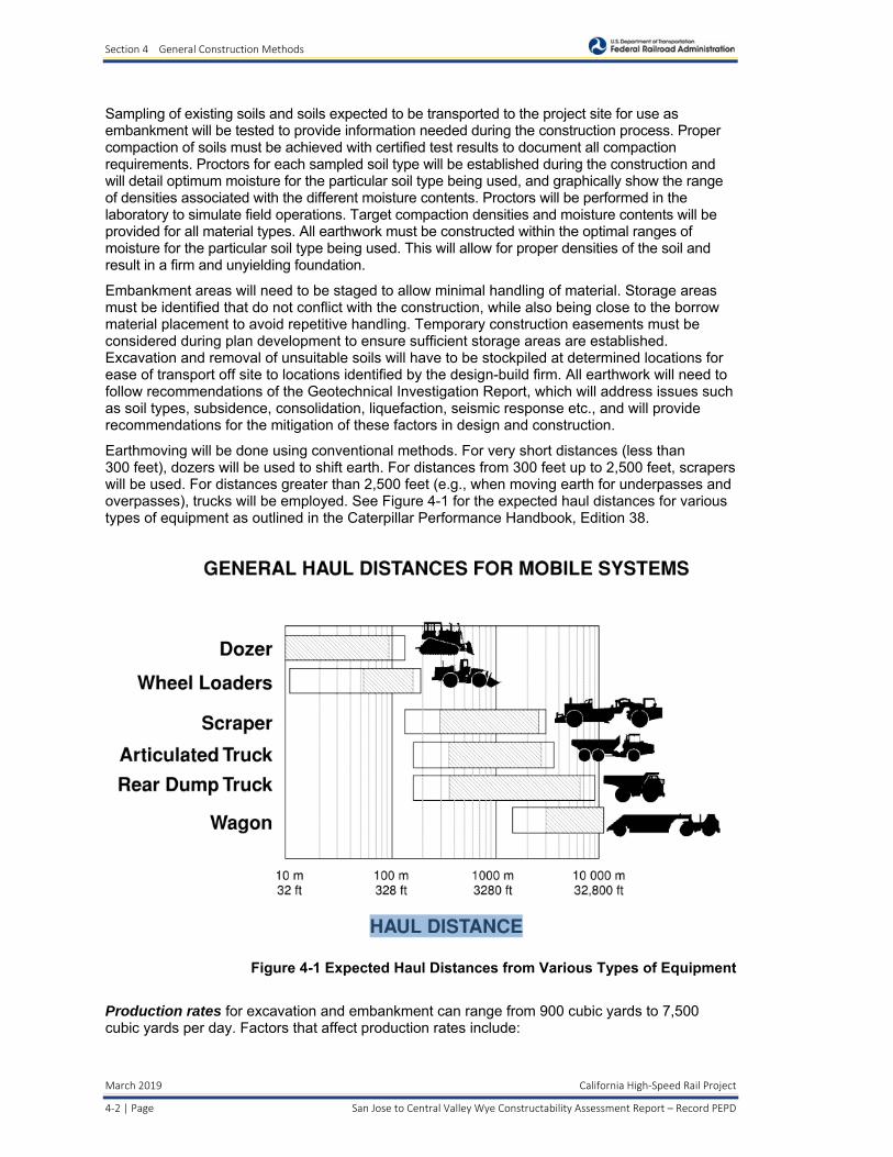
Earthmoving will be done using conventional methods. For very short distances (less than 300 feet), dozers will be used to shift earth. For distances from 300 feet up to 2,500 feet, scrapers will be used. For distances greater than 2,500 feet (e.g., when moving earth for underpasses and overpasses), trucks will be employed. See Figure 4-1 for the expected haul distances for various types of equipment as outlined in the Caterpillar Performance Handbook, Edition 38.
Figure 4-1 Expected Haul Distances from Various Types of Equipment
Production rates for excavation and embankment can range from 900 cubic yards to 7,500 cubic yards per day. Factors that affect production rates include:
Section 4 General Construction Methods
California High‐Speed Rail Project March 2019
San Jose to Central Valley Wye Constructability Assessment Report – Record PEPD Page | 4‐3
Haul route distances
Compaction rates of different soil types
Types of excavation required – lateral, ditch, subsoil, trench, or foundations
4.4 Roadway
Roadway reconstruction is a major component of the HSR project. Due to the alignment of the HSR, roads are being proposed to be raised, lowered, realigned, and constructed as overpasses or undercrossings, and at various locations, new frontage roads are proposed. After the earthwork operations are performed, roadway subgrade, base, and final pavement sections will be constructed. It is assumed major diversions to the existing roadways that will be grade separated will be avoided or minimized if necessary. Detours and temporary traffic control measures will be required to maintain traffic circulation during construction. The duration of each grade separation construction will vary depending on the type of temporary traffic control measure used (e.g. general detours provide a shorter construction duration).
It is anticipated that full and partial street closures will be needed for the reconstruction of roadways. The type of closures will be based on the proximity of alternate routes (these are analyzed in further detail in the environmental Transportation technical report). In general, a full roadway closure will result in a significantly shorter overall construction period than if a partial closure was to be used. This shorter period could be as much as a 50% reduction depending on the location. Preliminary staging concepts have been developed as part of these studies and detailed staging and maintenance of traffic will be developed during the final design phase.
It is anticipated that highway and roadway work associated with the HSR Project will be done using conventional methods and in the following sequence as necessary:
Demolition.
Utility relocations (utility relocation timing may influence highway work schedule), which could require trenching, segmental pipe construction, concrete pipe or conduit poured in situ, and storm drain catch basins poured in situ or placing precast units.
Excavation.
Grading.
Placing aggregate base.
Constructing concrete curb and gutter (in some cases this may be carried out before the previous stage), which can be done by building forms and pouring concrete in place or by using a curb and gutter placing machine.
Placing concrete or asphalt concrete base and top surfaces.
Coordination with all local agencies and Caltrans (for state highways) will be required as final design by the design-builder progresses.
Assumed Production Rates:
Subgrade ranges from 1,400 square yards to 1,800 square yards per day.
Base construction ranges from 1,000 square yards to 4,500 square yards per day.
Asphalt pavements ranges from 500 tons to 2,000 tons per day. Thickness of pavement section must be factored to determine the square yards that can be placed per day.
Concrete pavements range from 3,000 square yards to 5,000 square yards per day.

Section 4 General Construction Methods
March 2019 California High‐Speed Rail Project
4‐4 | Page San Jose to Central Valley Wye Constructability Assessment Report – Record PEPD
4.5 Drainage
Drainage will involve both permanent and temporary systems for track and road construction. Temporary systems will be developed to allow for construction activities that must be performed in dry conditions. Means and methods for temporary dewatering could include well point systems, sock drains, and bypass pumping from one retention area to another. Ground water considerations will need to be considered for all operations involving dewatering.
Permanent drainage features are anticipated to include closed pipe systems, open channels, swales, box culverts, inlets, and manholes. Production rates for installing permanent drainage will vary depending on depth of cut, soil conditions, installation methods, and structure type.
The HSR project drainage requirements are as follows:
Maintain existing drainage flow patterns.
Disperse on-site runoff to encourage local infiltration.
Improve existing drainage capacity if the HSR design exacerbates existing drainage problems or flooding where the existing system is known to be undersized.
Treat runoff from pollution-generating impervious surfaces to the maximum extent practicable to meet water quality objectives and water quality standards set forth by the California Regional Water Quality Control Board (RWQCB) before discharging to receiving waters.
The at-grade or track-on embankment segments will require drainage ditches or swales on both sides of the track to collect rainfall. The emphasis will be placed on on-site retention of runoff which will require the construction of detention basins or infiltration basins. These basins will be unlined and will be designed to remove litter, settleable solids (debris), total suspended solids, and pollutants; and encourage infiltration. For embankment segments supported by retaining walls, trackbed drainage will be collected and conveyed in a pipe system. Storm drains may also be incorporated behind the top of the retaining walls to accommodate peak events. All concentrated flow will be addressed in a noneroding manner.
Tracks set below grade or in a trench section will have drainage systems to collect stormwater and direct it to a pump station. Stormwater will be pumped to a retention/treatment basin outside the trench and released into a drainage facility.
For elevated track segments where the HSR crosses an unpaved rural landscape, the runoff will be collected and conveyed in pipes down the sides of the pier columns to infiltration swales. Where the guideway crosses developed urban areas, the runoff will again be conveyed in pipes down the sides of the piers but typically it will be discharged into the local stormwater drainage system.
Inside flood areas, transversal drainage would be designed to allow water permeability through the subgrade to avoid generating a dam effect. This drainage system will be composed of distributed transversal pipes.
Section 4 General Construction Methods
California High‐Speed Rail Project March 2019
San Jose to Central Valley Wye Constructability Assessment Report – Record PEPD Page | 4‐5
4.6 Structures
Five construction methods are being considered for the guideway. Methods include aerial structures, trench excavation and construction, at-grade construction, bored tunneling, and cut-and-cover tunneling. Costs and schedule are primary concerns for selection of any one alternative. Typically means and methods used by construction companies will drive both cost and schedule, but for this Constructability Assessment Report, production will be based on estimated values typically experienced during construction of similar magnitude.
4.6.1 Aerial Structures
The typical HSR bridge consists of a single-cell pre-stressed concrete box girder supporting two parallel tracks spanning approximately 110 ft. At certain locations, there are geometric constraints that require the bridge span to exceed 110 ft. up to a factor of 4. For this reason, it is unlikely that only one method of construction will be used.
The type of construction method selected by the contractor will depend on the geometry and location of the structure. The typical aerial sub-structure consists of cast-in place (CIP) bent cap, column(s) and a pile cap supported by structural steel, precast/pre-stressed piles, or cast-in-drilled hole (CIDH) piles. There are five types of superstructure construction methods proposed for the aerial guideway:
1. Full-span precast 2. Segmental precast 3. Balanced cantilever 4. CIP construction on falsework, 5. Steel plate girder or steel truss
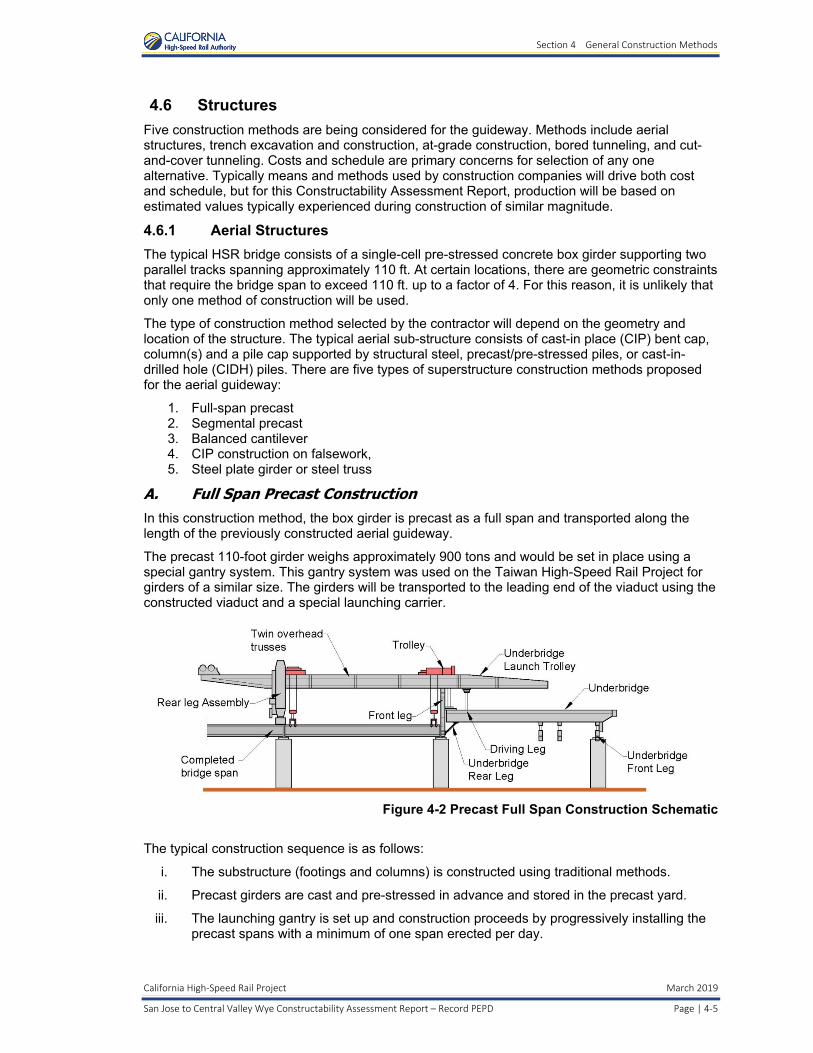
A. Full Span Precast Construction In this construction method, the box girder is precast as a full span and transported along the length of the previously constructed aerial guideway.
The precast 110-foot girder weighs approximately 900 tons and would be set in place using a special gantry system. This gantry system was used on the Taiwan High-Speed Rail Project for girders of a similar size. The girders will be transported to the leading end of the viaduct using the constructed viaduct and a special launching carrier.
Figure 4-2 Precast Full Span Construction Schematic
The typical construction sequence is as follows:
i. The substructure (footings and columns) is constructed using traditional methods.
ii. Precast girders are cast and pre-stressed in advance and stored in the precast yard.
iii. The launching gantry is set up and construction proceeds by progressively installing the precast spans with a minimum of one span erected per day.

Section 4 General Construction Methods
March 2019 California High‐Speed Rail Project
4‐6 | Page San Jose to Central Valley Wye Constructability Assessment Report – Record PEPD
iv. At locations where spans are cast-in-place on falsework or other construction method, the construction needs to be completed as an early item in order for the launching equipment to get across these areas without interrupting the construction process.
Figure 4-3 Taiwan High Speed Rail (Courtesy of Uwe Baier)
The advantages of the full span precast construction method are:
Fabrication of the box girder at the precast plant.
Rapid installation.
No ground level space requirements during the box girder installation phase.
Independent of the weather conditions.
The disadvantages are:
Need to have a large precast plant that can adapt to the dimensions and installation rate.
Need for dimensioning the structure for the extra load of box girders transported during the installation phase.
Need to acquire hoisting cranes, transport vehicles, and special placement machinery to position the box girders on the structure.
Dependent upon two machines (one per direction); therefore, any faults or equipment failure could impact the overall schedule.
Requires a different method for spans that exceed the typical length of 110 feet.
The erection rate will depend on how far the construction site is from the casting yard. The paper “Full-span Precast Launching Method (FPLM) Analysis with Dynamic Simulation – Case Studies of the Taiwan High-Speed Rail (THSR) Project”, Nai-Hsin, Tsung-Chih Chiu, Kuei-Yen Chen, October 2007, indicates an average of 1.1 segments per day is an assumed erection rate based on the historical production rates of each THSR segment. A precast casting yard can be placed at the center, next to the aerial to be constructed, that can deliver segments to each end of the aerial. The pre-casting yard would have to produce 2.2 segments per day to deliver segments to both ends of the viaduct.

Section 4 General Construction Methods
California High‐Speed Rail Project March 2019
San Jose to Central Valley Wye Constructability Assessment Report – Record PEPD Page | 4‐7
The sequence of construction and estimated construction duration is illustrated in Figure 4-4 Precast Full Span Sequence and Production Rate.
.
Figure 4-4 Precast Full Span Sequence and Production Rate
The cost of this method will depend on the schedule constraints and the size of the contract. The main expenses are the cost of the launching equipment and the requirement of having large precasting/storage yards next to the viaduct. For example, for a 25-mile aerial it is estimated that two launching gantries (each serving a half of the aerial) and two 20-acre casting/storage yards would be required to meet a 2.5-year superstructure construction duration. Prior to superstructure erection, the schedule should factor one year for design and manufacture of the gantry equipment and three months for installation. This procurement can occur at the same time as the precast yard construction and foundation installation. Cost can be reduced when the schedule is extended allowing the contractor to use the same erection equipment on each half of the aerial.
Appendix A includes illustrations of equipment layout and space requirements for typical full span precast construction along the Monterey Highway Guideway.
B. Span-by-Span (Precast) Segmental Construction In this construction method, the box girder is constructed with precast segments that are individually brought to the construction site and are joined together using prestressing tendons. This construction method, as well as the full span precast method, can be applied to long aerials with repetitive span length and with minimal angular variation. Both construction types are adequate for standard mass-produced structures typical in long viaducts. Generally, girders are simply supported to avoid having cast-in-place closure joints but continuity tendons can be provided at the bents when required. Having simple-supported girders allows a simpler post-tensioning layout.
The usual range for segmental construction is 100 ft. to 150 ft. For spans shorter than 100 ft., box girders are not as economical as beams. For spans longer than 150 ft., the

Section 4 General Construction Methods
March 2019 California High‐Speed Rail Project
4‐8 | Page San Jose to Central Valley Wye Constructability Assessment Report – Record PEPD
size/number of the segments becomes difficult to handle, the post-tensioning tendons become difficult to anchor to the pier tables, and the erection truss size becomes unpractical.
Figure 4-5 Precast Segmental Construction Schematic
The segment length is determined by the method of transport and the erection requirements. If the segments are transported using the existing ground infrastructure, each one is limited to a length of to 10 feet to 12 feet and weight of around 70 tons.
The typical construction sequence includes:
i. The substructure (foundations and columns) are constructed using traditional methods.
ii. The precast girder segments are precast in advance and stored in the precast yard.
iii. The launching gantry is set up and construction proceeds by progressively hoisting the segments and installing and tensioning the prestressing. A minimum of one span can be erected every four days.
iv. At locations where spans are cast-in-place on falsework or other construction method, the construction needs to be completed as an early item for the launching equipment to get across these areas without interrupting the construction process.
Section 4 General Construction Methods
California High‐Speed Rail Project March 2019
San Jose to Central Valley Wye Constructability Assessment Report – Record PEPD Page | 4‐9
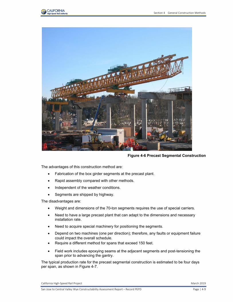
Figure 4-6 Precast Segmental Construction
The advantages of this construction method are:
Fabrication of the box girder segments at the precast plant.
Rapid assembly compared with other methods.
Independent of the weather conditions.
Segments are shipped by highway.
The disadvantages are:
Weight and dimensions of the 70-ton segments requires the use of special carriers.
Need to have a large precast plant that can adapt to the dimensions and necessary installation rate.
Need to acquire special machinery for positioning the segments.
Depend on two machines (one per direction); therefore, any faults or equipment failure could impact the overall schedule.
Require a different method for spans that exceed 150 feet.
Field work includes epoxying seams at the adjacent segments and post-tensioning the span prior to advancing the gantry.
The typical production rate for the precast segmental construction is estimated to be four days per span, as shown in Figure 4-7.

Section 4 General Construction Methods
March 2019 California High‐Speed Rail Project
4‐10 | Page San Jose to Central Valley Wye Constructability Assessment Report – Record PEPD
Figure 4-7 Precast Segmental Sequence and Production Rate
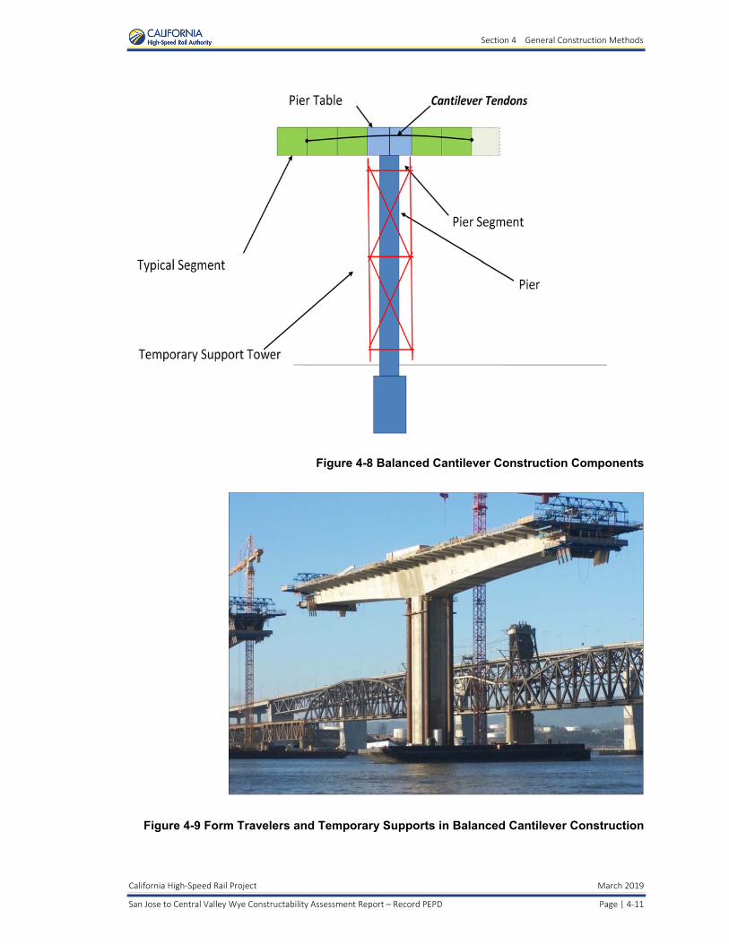
C. Balanced Cantilever (BC) Segmental Construction In this construction method, segments are placed in a symmetrical fashion about a bent. This construction method is well suited for long span construction over existing facilities that prevent placing equipment and temporary supports on the ground. The cantilever tendons are located in the deck slab and are anchored at the ends of the segments. The midspan tendons are responsible for transferring the positive moment between two completed cantilevers.
In the precast BC construction method, the segments are precast off-site in a precast yard. A single cell box girder is preferred for precast construction to minimize the segment weight and to allow for a 3-point support under the webs during storage.
The segments are transported to the construction site and installed incrementally onto the existing portion of the cantilever. The erection can be performed by ground cranes hoisting devices located atop of deck or by a self-launching gantry. This method has more flexibility than the span-by-span segmental construction method because the span length can be increased without modifying the erection equipment.
In the CIP BC construction method, form travelers are used to form, reinforce, and cast a segment at the tip of the cantilever. Form travelers work in pairs (one at each end of the balanced cantilever) to maintain the balanced condition. The construction cycle takes up to one week from when the segment reinforcement is placed, concrete is cast, and the traveler advances to the next position. The segment length is typically longer than with precast segment construction because no transportation is required.
In both methods, temporary supports may be required to avoid over-stressing the bent column during erection.
Section 4 General Construction Methods
California High‐Speed Rail Project March 2019
San Jose to Central Valley Wye Constructability Assessment Report – Record PEPD Page | 4‐11
Figure 4-8 Balanced Cantilever Construction Components
Figure 4-9 Form Travelers and Temporary Supports in Balanced Cantilever Construction
Section 4 General Construction Methods
March 2019 California High‐Speed Rail Project
4‐12 | Page San Jose to Central Valley Wye Constructability Assessment Report – Record PEPD
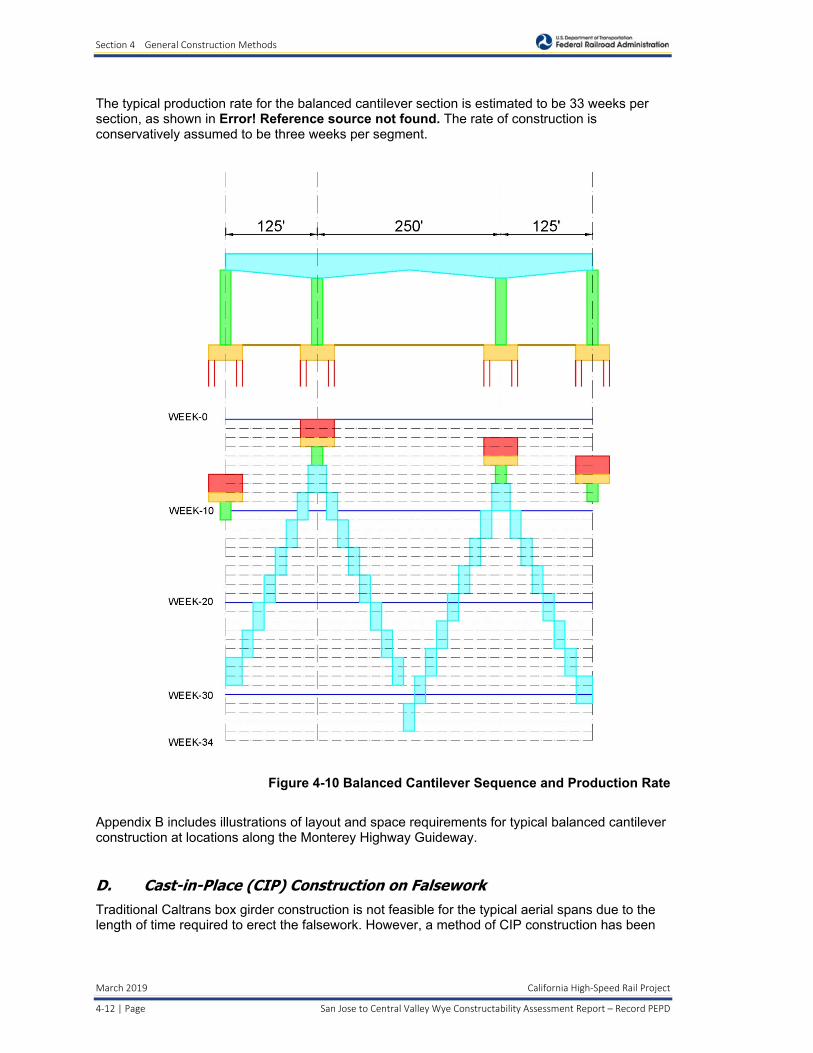
The typical production rate for the balanced cantilever section is estimated to be 33 weeks per section, as shown in Error! Reference source not found. The rate of construction is conservatively assumed to be three weeks per segment.
Figure 4-10 Balanced Cantilever Sequence and Production Rate
Appendix B includes illustrations of layout and space requirements for typical balanced cantilever construction at locations along the Monterey Highway Guideway.
D. Cast-in-Place (CIP) Construction on Falsework Traditional Caltrans box girder construction is not feasible for the typical aerial spans due to the length of time required to erect the falsework. However, a method of CIP construction has been
Section 4 General Construction Methods
California High‐Speed Rail Project March 2019
San Jose to Central Valley Wye Constructability Assessment Report – Record PEPD Page | 4‐13
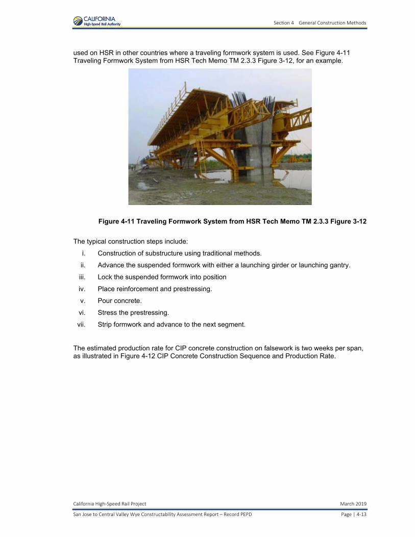
used on HSR in other countries where a traveling formwork system is used. See Figure 4-11 Traveling Formwork System from HSR Tech Memo TM 2.3.3 Figure 3-12, for an example.
Figure 4-11 Traveling Formwork System from HSR Tech Memo TM 2.3.3 Figure 3-12
The typical construction steps include:
i. Construction of substructure using traditional methods.
ii. Advance the suspended formwork with either a launching girder or launching gantry.
iii. Lock the suspended formwork into position
iv. Place reinforcement and prestressing.
v. Pour concrete.
vi. Stress the prestressing.
vii. Strip formwork and advance to the next segment.
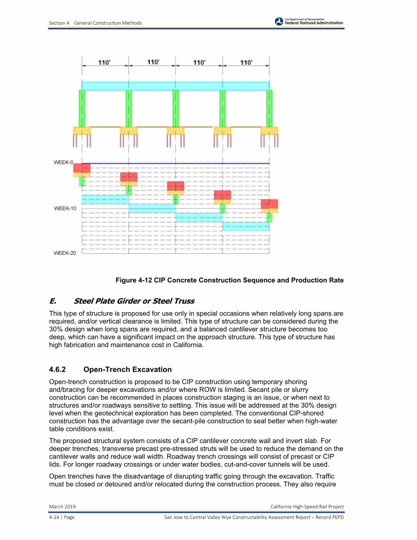
The estimated production rate for CIP concrete construction on falsework is two weeks per span, as illustrated in Figure 4-12 CIP Concrete Construction Sequence and Production Rate.
Section 4 General Construction Methods
March 2019 California High‐Speed Rail Project
4‐14 | Page San Jose to Central Valley Wye Constructability Assessment Report – Record PEPD
Figure 4-12 CIP Concrete Construction Sequence and Production Rate
E. Steel Plate Girder or Steel Truss This type of structure is proposed for use only in special occasions when relatively long spans are required, and/or vertical clearance is limited. This type of structure can be considered during the 30% design when long spans are required, and a balanced cantilever structure becomes too deep, which can have a significant impact on the approach structure. This type of structure has high fabrication and maintenance cost in California.
4.6.2 Open-Trench Excavation
Open-trench construction is proposed to be CIP construction using temporary shoring and/bracing for deeper excavations and/or where ROW is limited. Secant pile or slurry construction can be recommended in places construction staging is an issue, or when next to structures and/or roadways sensitive to settling. This issue will be addressed at the 30% design level when the geotechnical exploration has been completed. The conventional CIP-shored construction has the advantage over the secant-pile construction to seal better when high-water table conditions exist.
The proposed structural system consists of a CIP cantilever concrete wall and invert slab. For deeper trenches, transverse precast pre-stressed struts will be used to reduce the demand on the cantilever walls and reduce wall width. Roadway trench crossings will consist of precast or CIP lids. For longer roadway crossings or under water bodies, cut-and-cover tunnels will be used.
Open trenches have the disadvantage of disrupting traffic going through the excavation. Traffic must be closed or detoured and/or relocated during the construction process. They also require

Section 4 General Construction Methods
California High‐Speed Rail Project March 2019
San Jose to Central Valley Wye Constructability Assessment Report – Record PEPD Page | 4‐15
the relocation of underground utilities running perpendicular to the trench. Ground water management may be required depending on the depth of the water table. Also, this construction method may require temporary shoring/bracing during the construction process. Considerations to roadways nearby must be addressed to ensure settlement or undermining of the roadway is not occurring. Settlement and vibration monitoring is recommended during this process where construction is close to existing roadways and/or structures. Production rates can vary depending on the types of soils/rocks/obstructions encountered, types of equipment employed, and the contractor’s means and methods.
4.6.3 Cut-and-Cover Tunnel
The construction method for cut-and-cover tunnels is similar to the open trench construction with the added component of constructing a CIP top slab to cover the trench. With cut-and-cover tunnels, roadway crossings will have to be detoured and/or closed during construction. Temporary diversion channels will need to be provided when tunnels cross through bodies of water. Construction staging is important to building cut-and-cover tunnels. Under certain circumstances, this type of construction is more cost effective than tunneling with tunnel boring machines.
4.6.4 Bored Tunnels
Bored tunnels are only considered when the length and depth of the tunnel allows it to be cost effective compared to the cut-and-cover construction. Bored tunnels are considered primarily for the Pacheco Pass Subsection. Construction considerations are addressed in the Conceptual Tunnel Design and Constructability Considerations for Pacheco Pass prepared by HNTB Corporation dated November 2017.
4.6.5 Retaining Walls
CIP retaining walls are anticipated where limited construction space is a concern. Production rates for casting retaining walls are estimated between 100 to 200 square feet per day.
Retained Earth Walls are anticipated in conjunction with retaining walls. Retained Earth Walls require straps or rods connected to the backside of the wall panels and are placed in the embankment for wall stability. Since the walls are placed as panels with the embankment, this method of construction expedites the overall embankment sequence. Production rates for these walls must be correlated to the production rates for placing embankment which is covered under the earthwork section. The walls require well-draining soils with no organics.
4.7 Track
At this stage of the project, a track system has not been selected. The design assumes conventional ballast track for at-grade alignments with the provision for ballastless or direct fixation track on the aerial viaducts/bridges, trenches, and tunnels.
Since the HSR must meet FRA Class 8/9 Track Standards, the construction methods and Track Tolerance Testing (FRA’s Track Safety Standards Compliance Manual, Chapter 6) will follow 49 CFR 213 requirements for HSR. Note: Trackwork for the blended, at-grade alternative will meet standards for FRA Class 6 for operating speeds up to 110 mph.
A. Conventional Ballast Track Worldwide, the most common system is the ballasted track system. This system includes the track roadbed, sub-ballast, ballast, ties, and rail with rail fasteners. Construction rates depend on the rail equipment and skilled team composition of the contractor. Mats can also be used with ballasted track to minimize vibrations.

Section 4 General Construction Methods
March 2019 California High‐Speed Rail Project
4‐16 | Page San Jose to Central Valley Wye Constructability Assessment Report – Record PEPD
Figure 4-13 Ballast Track - Schotteroberbau
Figure 4-14 Ballast Track with Mats - Japan
Figure 4-15 Ballast Track Turnouts

Section 4 General Construction Methods
California High‐Speed Rail Project March 2019
San Jose to Central Valley Wye Constructability Assessment Report – Record PEPD Page | 4‐17
B. Direct Fixation or Slab Track System This type of track system does not have any ballast in the Guideway. In its simplest form, this consists of a continuous slab of concrete (like a highway structure) with the rails supported directly on its upper surface (using a resilient pad). Variations include continuous in situ placing of a reinforced concrete slab or the use of pre-cast pre-stressed concrete units laid on a base layer. Units can be produced in casting yards with bridge/viaduct precast units and installed with them.
Figure 4-16 Slab Track - China HSR
Figure 4-17 Track Turnouts - China HSR
Section 4 General Construction Methods
March 2019 California High‐Speed Rail Project
4‐18 | Page San Jose to Central Valley Wye Constructability Assessment Report – Record PEPD
C. Curve Straightening The primary trackwork construction for the blended, at-grade alternative will be for curve straightening to allow for increased operational speeds on the corridor. This work has been categorized into four types of track shifts:
1. Less than one foot – Existing track is shifted in one work window and the existing OCS poles will remain.
2. More than one foot and less than 10 feet – Existing track is shifted over several work windows and the existing OCS poles will need to be relocated (via construction of new OCS poles to maintain existing operations during non-work windows).
3. More than 10 feet and less than 21.34 feet – New OCS poles and tracks are constructed alongside the existing tracks while allowing existing service to be maintained. Temporary OCS poles may be required where the existing OCS poles will need to be removed to construct the new track.
4. More than 21.34 feet – New OCS poles and tracks are constructed alongside the existing tracks while existing service will remain unaffected.
See Appendix H for additional information on track shift work and approach.
D. Vertical Alignment Adjustments The existing track profile will need to be modified to allow for increased operational speeds on the corridor. With the assumption that the existing ballast layer is 18 inches deep, this work has been categorized into three types of vertical adjustments:
1. Raising or Lowering up to six inches – The track profile will be adjusted through changes to the ballast layer only. The sub-ballast layer would remain intact. The OCS poles can remain in place and only the contact wire would be adjusted.
2. Raising greater than six inches – The track profile will be adjusted through reconstruction of the trackbed (ballast and sub-ballast layers). The OCS poles will need to be reconstructed.
3. Lowering greater than six inches - The track profile will be adjusted through reconstruction of the trackbed (ballast and sub-ballast layers). The OCS poles will need to be reconstructed.
See Appendix H for additional information on track shift work and approach.
E. OCS Adjustments The existing OCS system between CP Coast to south of the Caltrain Tamien Station will need to be modified based on the alignment modifications to allow for increased operational speeds on the corridor. This work has been categorized into four types of OCS modifications:
1. New OCS System – As noted above, based on the horizontal and/or vertical adjustment to the track profile, new OCS poles will need to be constructed.
2. OCS Pole Displacement – As noted above, based on the horizontal and/or vertical adjustment to the track profile, new OCS poles will need to be relocated.
3. OCS Contact Wire Displacement - As noted above, based on the horizontal adjustment to the track alignment, the OCS contact wire would be adjusted, and the existing OCS pole would remain.
4. OCS Contact Wire Vertical Displacement - As noted above, based on the vertical adjustment to the track profile, the OCS contact wire would be adjusted, and the

Section 4 General Construction Methods
California High‐Speed Rail Project March 2019
San Jose to Central Valley Wye Constructability Assessment Report – Record PEPD Page | 4‐19
existing OCS pole will need to be reconstructed if the adjustment was more than could be accommodated on the existing pole.
See Appendix H for additional information on OCS adjustments and approach.
4.8 Utility Relocations/Adjustments/Construction
Since the HSR alignments traverses developed urban areas and farmland, existing utilities such as water supply facilities, etc., are anticipated to be constructed during the site preparation stage. Detailed information for utility relocations/adjustments is contained in the High Risk and Major Utilities Conflict Memorandum. Schedule and contract arrangements will need to be developed for utility relocation; oil pipelines, high pressure gas lines, major irrigation, fiber optic, water mains, and wells.

Section 5 Subsection Construction
California High‐Speed Rail Project March 2019
San Jose to Central Valley Wye Constructability Assessment Report – Record PEPD Page | 5‐1
5 SUBSECTION CONSTRUCTION
Specific subsection construction challenges and issues are described in this section. The engineering drawings will provide construction staging and phasing plans. The drawings will also underline how some of the constructability issues are proposed to be resolved.
5.1 San Jose Diridon Station Approach
5.1.1 Alternative 1
This is an aerial structure option to build the San Jose High-Speed Station over the existing Caltrain San Jose Diridon Station with a connection between both stations through an intermediate mezzanine.
The HSR alignment begins to rise at station 2403+00 with the aerial structure beginning at station 2415+00 and continuing into the next section.
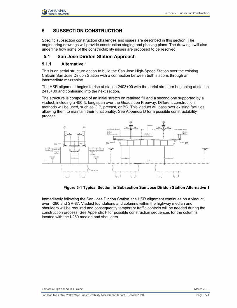
The structure is composed of an initial stretch on retained fill and a second one supported by a viaduct, including a 450-ft. long span over the Guadalupe Freeway. Different construction methods will be used, such as CIP, precast, or BC. This viaduct will pass over existing facilities allowing them to maintain their functionality. See Appendix D for a possible constructability process.
Figure 5-1 Typical Section in Subsection San Jose Diridon Station Alternative 1
Immediately following the San Jose Diridon Station, the HSR alignment continues on a viaduct over I-280 and SR-87. Viaduct foundations and columns within the highway median and shoulders will be required and consequently temporary traffic controls will be needed during the construction process. See Appendix F for possible construction sequences for the columns located with the I-280 median and shoulders.

Section 5 Subsection Construction
March 2019 California High‐Speed Rail Project
5‐2 | Page San Jose to Central Valley Wye Constructability Assessment Report – Record PEPD
5.1.2 Alternative 2
This alternative is structurally similar to Alternative 1, with the main difference being a longer structure length beginning at station 2288+00.
Figure 5-2 Typical Section in Subsection San Jose Diridon Station Alternative 2
For both Alternatives 1 and 2, temporary traffic controls will be required on the local roadways to construct the HSR. In some instances, significant changes to the local street movement, such as two-way traffic control or full street closures and detours will be required. Coordination with the City of San Jose will be required in the next project phase to develop detailed traffic management plans.
5.1.3 Alternative 4
This is a blended at-grade alternative to build the San Jose HSR Station at-grade within the existing Caltrain San Jose Diridon Station by raising and extending two existing platforms, and constructing a pedestrian overcrossing to connect the station building to the HSR platforms.
South of the San Jose Dirdion Station, the track alignment will follow the existing Caltrain corridor and add a third track from Los Gatos Creek to the Caltrain Tamien Station. The alignment is on retained fill to minimize the need for additional ROW. Some of the existing structures will be replaced where shifting of the track or a change in the track profile will preclude use of the existing structure. There will be new single-track structures over I-280 and SR87 (Guadalupe Freeway). The construction of the structure over SR87 will require single-track operations of the VTA light rail system between the Tamien and Virginia stations. Different construction methods for these new structures will be used, such as CIP, precast, or BC. See Appendix D for a possible constructability process.

Section 5 Subsection Construction
California High‐Speed Rail Project March 2019
San Jose to Central Valley Wye Constructability Assessment Report – Record PEPD Page | 5‐3
Figure 5-3 Typical Section South of I-280 in Subsection San Jose Diridon Station Alternative 4
Viaduct foundations and columns within the highway median and shoulders will be required and consequently temporary traffic controls will be needed during the construction process.
5.2 Monterey Corridor
Three different alternatives are designed for the Monterey Corridor: 1) an at-grade/embankment alignment adjacent to the existing UPRR ROW, 2) an aerial alignment adjacent to the existing UPRR ROW, and 3) a blended, at-grade alignment within the existing UPRR ROW.
Each alternative has its own alignment and construction methods that should be adapted to their surrounding conditions.
5.2.1 Monterey Corridor At-Grade/Embankment (Alternative 2)
This section alignment runs parallel to and in between Monterey Road and the UPRR railway line with cut-and-fill slopes, retaining walls, and intrusion barriers as required. This subsection includes several roadway grade separations that are both over- and undercrossings.

Section 5 Subsection Construction
March 2019 California High‐Speed Rail Project
5‐4 | Page San Jose to Central Valley Wye Constructability Assessment Report – Record PEPD
Figure 5-4 Typical Section in Subsection Monterey Corridor (At Grade)
Due to site constraints and the need for Monterey Road and UPRR to maintain operations, it is assumed that the construction process will begin with the relocation of existing utilities, then the construction of Monterey Road and the grade separations, and then the construction of HSR structures and facilities including retaining walls and bridges. In general, shoofly tracks will be constructed near the HSR tracks for UPRR use during construction of the UPRR bridge at undercrossing locations. Then, the final HSR bridge and tracks will be constructed after the UPRR permanent alignments are restored. For construction staging sequencing at the grade separations see the plan sets in the March 2019 PEPD submittal.
5.2.2 Monterey Corridor Viaduct (Alternative 1)
This is an elevated alignment which generally runs within the Monterey Road median and is supported by a 2-track girder box. The viaduct structure deck should be precast for 110 ft. spans and BC for larger spans.
Due to the viaduct foundation dimensions, the adjacent roadway areas must be temporarily occupied during the construction process so temporary traffic control measures will be required. One possible process would be to construct the viaduct foundations in three stages to maintain two lanes of traffic in each direction. Dedicated left-turn lanes would be eliminated during the process (to stay within existing ROW), but major, signalized intersections would remain open. Nighttime work involving lane closures resulting in one lane of traffic in each direction may also be utilized. See Appendix G for conceptual plans.

Section 5 Subsection Construction
California High‐Speed Rail Project March 2019
San Jose to Central Valley Wye Constructability Assessment Report – Record PEPD Page | 5‐5
Figure 5-5 Typical Section in Subsection Monterey Corridor (Viaduct
5.2.3 Monterey Corridor Blended At-Grade (Alternative 4)
This section runs at grade and parallel alongside Monterey Road through San Jose. It is in the UPRR ROW so temporary traffic handling measures are minimal. UPRR and Blended/HSR tracks are substantially within the existing UPRR ROW.
Figure 5-6 Typical Section in Subsection Monterey Corridor (Blended At-Grade)
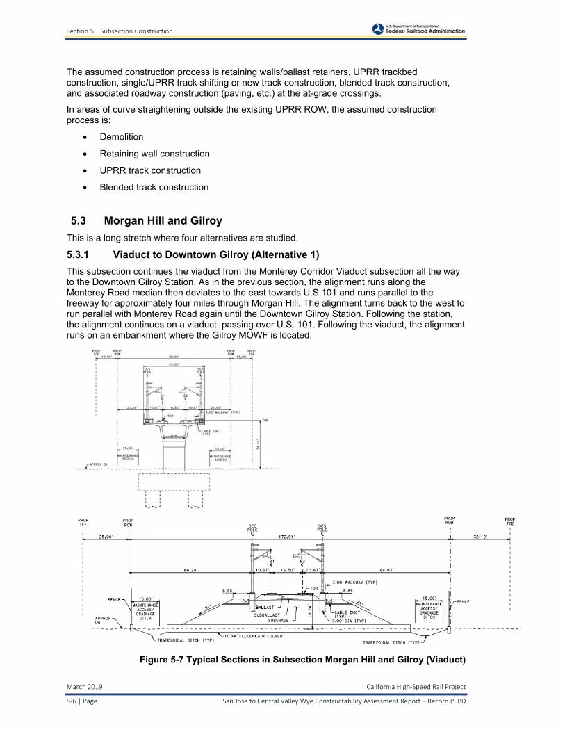
Section 5 Subsection Construction
March 2019 California High‐Speed Rail Project
5‐6 | Page San Jose to Central Valley Wye Constructability Assessment Report – Record PEPD
The assumed construction process is retaining walls/ballast retainers, UPRR trackbed construction, single/UPRR track shifting or new track construction, blended track construction, and associated roadway construction (paving, etc.) at the at-grade crossings.
In areas of curve straightening outside the existing UPRR ROW, the assumed construction process is:
Demolition
Retaining wall construction
UPRR track construction
Blended track construction
5.3 Morgan Hill and Gilroy
This is a long stretch where four alternatives are studied.
5.3.1 Viaduct to Downtown Gilroy (Alternative 1)
This subsection continues the viaduct from the Monterey Corridor Viaduct subsection all the way to the Downtown Gilroy Station. As in the previous section, the alignment runs along the Monterey Road median then deviates to the east towards U.S.101 and runs parallel to the freeway for approximately four miles through Morgan Hill. The alignment turns back to the west to run parallel with Monterey Road again until the Downtown Gilroy Station. Following the station, the alignment continues on a viaduct, passing over U.S. 101. Following the viaduct, the alignment runs on an embankment where the Gilroy MOWF is located.
Figure 5-7 Typical Sections in Subsection Morgan Hill and Gilroy (Viaduct)

Section 5 Subsection Construction
California High‐Speed Rail Project March 2019
San Jose to Central Valley Wye Constructability Assessment Report – Record PEPD Page | 5‐7
There are different construction methods assumed for this section.
At the beginning, where the HSR alignment is over roadway median, the median will be redesigned to accommodate the viaduct foundations. The foundation dimensions will encroach into the roadway lanes, so temporary traffic handling measures will be required for the construction process.
Within Morgan Hill, where the alignment deviates to the east, no roadways are affected and some buildings will need to be demolished before beginning construction.
It is assumed the viaduct will be constructed using standard methods and decks will be precast except at long spans where BC is assumed.
For purposes of discussion, the following provides an overview of probable construction activities and durations for the long viaduct.
The total elevated viaduct structure for this segment is approximately 138,000 feet long, composed of several different structure types:
o Typical Spans (110 feet long), approximately 1,185 spans total
o Longer Spans (up to 150 feet long), approximately 30 spans total
o Balanced Cantilever Spans (up to 410 feet long), approximately 47 spans total
o Straddle Bent Spans (900 feet total length) crossing UPRR
Factors that affect the viaduct work and control the construction schedule include:
o Ordering, fabricating, delivery, and setup of specialized gantries used for installing the full span precast girders and establishment of the precast yards, including equipment procurement, operations startup, and production rates. It is estimated that two precast yards will be needed for the Monterey Highway Aerial Structure (1-1/2 years).
o Construction of 1,266 foundations and columns: 11,394 days (based on nine days per foundation using CIDH and columns) of total construction time, assuming completion in 3-1/4 years with 10 teams.
o Estimate that two gantries will be needed for the entire Monterey Highway Aerial Structure to achieve the 2-year construction schedule (based on 1 span per day per gantry).
o Scheduling the completion of the balanced cantilever spans and straddle bents prior to advancing the gantries over those locations.
o It is estimated that 3.5 years will be needed for the Monterey Highway Aerial Structure.
The remaining part of the section involves the construction of large embankments, which requires drainage/floodplain control measures and short viaducts to allow water flow.
5.3.2 Embankment to Downtown Gilroy (Alternative 2)
This section runs at grade parallel alongside Monterey Road through Morgan Hill. It is placed between UPRR tracks and Monterey Road so temporary traffic handling measures will be needed. UPRR and HSR tracks are separated by a concrete retaining wall.
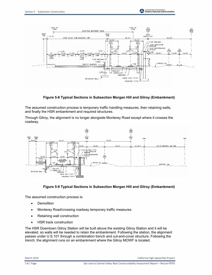
Section 5 Subsection Construction
March 2019 California High‐Speed Rail Project
5‐8 | Page San Jose to Central Valley Wye Constructability Assessment Report – Record PEPD
Figure 5-8 Typical Sections in Subsection Morgan Hill and Gilroy (Embankment)
The assumed construction process is temporary traffic handling measures, then retaining walls, and finally the HSR embankment and required structures.
Through Gilroy, the alignment is no longer alongside Monterey Road except where it crosses the roadway.
Figure 5-9 Typical Sections in Subsection Morgan Hill and Gilroy (Embankment)
The assumed construction process is:
Demolition
Monterey Road/crossing roadway temporary traffic measures
Retaining wall construction
HSR track construction
The HSR Downtown Gilroy Station will be built above the existing Gilroy Station and it will be elevated, so walls will be needed to retain the embankment. Following the station, the alignment passes under U.S.101 through a combination trench and cut-and-cover structure. Following the trench, the alignment runs on an embankment where the Gilroy MOWF is located.
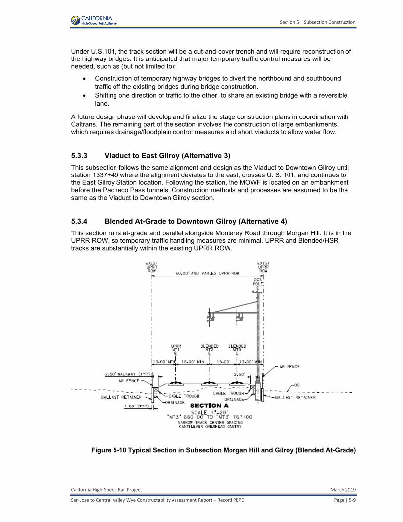
Section 5 Subsection Construction
California High‐Speed Rail Project March 2019
San Jose to Central Valley Wye Constructability Assessment Report – Record PEPD Page | 5‐9
Under U.S.101, the track section will be a cut-and-cover trench and will require reconstruction of the highway bridges. It is anticipated that major temporary traffic control measures will be needed, such as (but not limited to):
Construction of temporary highway bridges to divert the northbound and southbound traffic off the existing bridges during bridge construction.
Shifting one direction of traffic to the other, to share an existing bridge with a reversible lane.
A future design phase will develop and finalize the stage construction plans in coordination with Caltrans. The remaining part of the section involves the construction of large embankments, which requires drainage/floodplain control measures and short viaducts to allow water flow.
5.3.3 Viaduct to East Gilroy (Alternative 3)
This subsection follows the same alignment and design as the Viaduct to Downtown Gilroy until station 1337+49 where the alignment deviates to the east, crosses U. S. 101, and continues to the East Gilroy Station location. Following the station, the MOWF is located on an embankment before the Pacheco Pass tunnels. Construction methods and processes are assumed to be the same as the Viaduct to Downtown Gilroy section.
5.3.4 Blended At-Grade to Downtown Gilroy (Alternative 4)
This section runs at-grade and parallel alongside Monterey Road through Morgan Hill. It is in the UPRR ROW, so temporary traffic handling measures are minimal. UPRR and Blended/HSR tracks are substantially within the existing UPRR ROW.
Figure 5-10 Typical Section in Subsection Morgan Hill and Gilroy (Blended At-Grade)

Section 5 Subsection Construction
March 2019 California High‐Speed Rail Project
5‐10 | Page San Jose to Central Valley Wye Constructability Assessment Report – Record PEPD
The assumed construction process is retaining walls/ballast retainers, UPRR trackbed construction, single/UPRR track shifting or new track construction, blended track construction, and associated roadway construction (paving, etc.) for the at-grade crossings.
In areas of curve straightening that is outside the existing UPRR ROW, the assumed construction process is:
Demolition
Retaining wall construction
UPRR track construction
Blended track construction
The HSR Downtown Gilroy Station will be at-grade and built on the existing Gilroy Station tracks and platforms. Following the station, the alignment passes under U.S.101 on the existing tracks. Following south of U.S.101, the UPRR tracks will be realigned with the HSR alignment running on an embankment where the Gilroy MOWF is located.
No impacts are expected to U.S.101.
5.4 Gilroy and Pacheco Pass Tunnels (Alternatives 1-4)
There are two HSR alignments for the area in southern Gilroy through Pacheco Pass, both include two tunnels. The only difference between the two alternatives is the alignment of Tunnel 1, with the first alternative coming from Downtown Gilroy and the second alternative coming from East Gilroy. Both alternatives have the same east portal location for Tunnel 1.
The tunnels lengths are as follows:
Table 5-1 San Jose to Merced Tunnel Lengths
TUNNEL 1 TUNNEL 1 - DOWNTOWN GILROY ALIGNMENT
PORTAL 1 PORTAL 2 TUNNEL LENGTH (ft) 2252+02.00 2339+16.00 8,714
TUNNEL 1 - EAST GILROY ALIGNMENT
PORTAL 1 PORTAL 2 TUNNEL LENGTH (ft)
2184+53.00 2268+86.00 8,433 TUNNEL 2 - DEEP ALIGNMENT
PORTAL 1 PORTAL 2 TUNNEL LENGTH (ft) 3322+62.00 4034+00.00 71,138
Both tunnels have typical sections with 28 foot interior diameters. Track centerline distances vary: Tunnel 1: 66 ft. apart and Tunnel 2: 132 ft. apart.
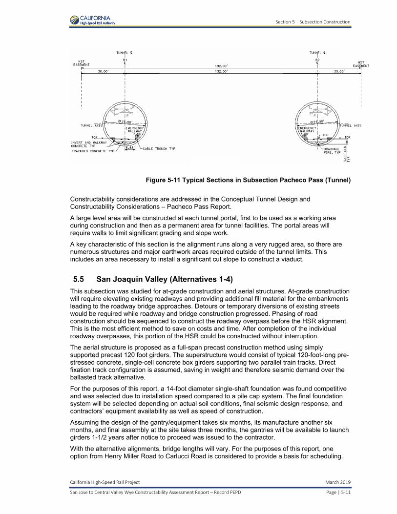
Section 5 Subsection Construction
California High‐Speed Rail Project March 2019
San Jose to Central Valley Wye Constructability Assessment Report – Record PEPD Page | 5‐11
Figure 5-11 Typical Sections in Subsection Pacheco Pass (Tunnel)
Constructability considerations are addressed in the Conceptual Tunnel Design and Constructability Considerations – Pacheco Pass Report.
A large level area will be constructed at each tunnel portal, first to be used as a working area during construction and then as a permanent area for tunnel facilities. The portal areas will require walls to limit significant grading and slope work.
A key characteristic of this section is the alignment runs along a very rugged area, so there are numerous structures and major earthwork areas required outside of the tunnel limits. This includes an area necessary to install a significant cut slope to construct a viaduct.
5.5 San Joaquin Valley (Alternatives 1-4)
This subsection was studied for at-grade construction and aerial structures. At-grade construction will require elevating existing roadways and providing additional fill material for the embankments leading to the roadway bridge approaches. Detours or temporary diversions of existing streets would be required while roadway and bridge construction progressed. Phasing of road construction should be sequenced to construct the roadway overpass before the HSR alignment. This is the most efficient method to save on costs and time. After completion of the individual roadway overpasses, this portion of the HSR could be constructed without interruption.
The aerial structure is proposed as a full-span precast construction method using simply supported precast 120 foot girders. The superstructure would consist of typical 120-foot-long pre-stressed concrete, single-cell concrete box girders supporting two parallel train tracks. Direct fixation track configuration is assumed, saving in weight and therefore seismic demand over the ballasted track alternative.
For the purposes of this report, a 14-foot diameter single-shaft foundation was found competitive and was selected due to installation speed compared to a pile cap system. The final foundation system will be selected depending on actual soil conditions, final seismic design response, and contractors’ equipment availability as well as speed of construction.
Assuming the design of the gantry/equipment takes six months, its manufacture another six months, and final assembly at the site takes three months, the gantries will be available to launch girders 1-1/2 years after notice to proceed was issued to the contractor.
With the alternative alignments, bridge lengths will vary. For the purposes of this report, one option from Henry Miller Road to Carlucci Road is considered to provide a basis for scheduling.

Section 5 Subsection Construction
March 2019 California High‐Speed Rail Project
5‐12 | Page San Jose to Central Valley Wye Constructability Assessment Report – Record PEPD
Structures total length is 26,943 feet, so estimated working timetables are:
Gantry/equipment design, procurement, assembly: 1-1/2 years
120 foot spans for 26,943 feet of bridge with approximately 225 foundations: 2,025 days of total construction time (based on nine days per foundation using CIDH and columns), assume completion in 405 days with five teams.
o Spans per day was estimated in Section 4. General Construction Methods. Substructure construction must be complete before the superstructure can begin and with an assumed lag time of 100 days between the start of substructure work to the start of superstructure work, it is estimated that the entire 26,943 foot bridge would take approximately 205 days to complete.
Other specific constructability concerns in the San Joaquin Valley Crossing subsection include:
Major waterway crossings including large irrigation canals and: o San Luis Creek o San Luis Wasteway o Los Banos Creek o San Luis Drain No. 1 o Mud Slough o Boundary Drain o Devon Drain o Drain #1 o West Delta Drain o Poso Drain o Belmont Drain o West San Juan Drain o West San Juan Drain #1
Minimizing disturbances in Caltrans ROW
Spanning across I-5 and Whitworth Road
Maintaining access for agricultural operations
Interface between San Joaquin Valley Crossing and Merced to Fresno Wye

Section 6 Construction Staging Areas
California High‐Speed Rail Project March 2019
San Jose to Central Valley Wye Constructability Assessment Report – Record PEPD Page | 6‐1
6 CONSTRUCTION STAGING AREAS
The construction staging areas will house: incoming materials; areas for material preparation, storage and maintenance of equipment, operations preparation, and construction offices; and allow good housekeeping throughout the alignment (see the plans for all the construction staging areas).
Each method of construction will have its own staging area requirements. Staging areas for span-by-span segmental, BC, and CIP construction methods are not as critical to the construction footprint as the full span method for the following reasons, the site does not need to be as large and bridge elements can be transported to/from the site using local streets. On the other hand, staging areas for methods other than full span construction impact local roads more in terms of lane closures and detours. The larger construction staging areas (for use as viaduct pre-casting yards) for Alternatives 1 and 3, as well as limited construction staging areas available for Alternative 4 are shown below.
6.1 Monterey Viaduct Alignment Using Full Span Construction
6.1.1 Location
Figure 6-1 Far North End Staging Area, Alternatives 1 and 3 (Sta 310+00 near Capitol Caltrain)

Section 6 Construction Staging Areas
March 2019 California High‐Speed Rail Project
6‐2 | Page San Jose to Central Valley Wye Constructability Assessment Report – Record PEPD
Figure 6-2 Central Staging Area, Alternatives 1 and 3 (Sta 920+00 near Morgan Hill)
Figure 6-3 South End Staging Area, Alternative 1 (Sta 1575+00 in Gilroy)

Section 6 Construction Staging Areas
California High‐Speed Rail Project March 2019
San Jose to Central Valley Wye Constructability Assessment Report – Record PEPD Page | 6‐3
Figure 6-44South End Staging Area, Alternative 3 (Sta 1605+00 in Gilroy)
6.1.2 Description of Site
Three in-line staging areas are shown in Section 6-1:
Figure 6-1 Far North End Staging Area, Alternatives 1 and 3 (Sta 310+00 near Capitol Caltrain)
Figure 6-2 Central Staging Area, Alternatives 1 and 3 (Sta 920+00 near Morgan Hill)
Figure 6-3 South End Staging Area, Alternative 1 (Sta 1575+00 in Gilroy)
Figure 6-44South End Staging Area, Alternative 3 (Sta 1605+00 in Gilroy)
The alignment between the Far North End and South End staging areas is constrained because the HSR alignment runs between the UPRR ROW and Monterey Highway.
6.1.3 Criteria Compliance
Each of the three staging areas comply with the criteria required for the full-span precast construction method: in-line with the HSR alignment and at least 35 acres. The 35 acres includes 21 acres for the precast yard (see Appendix C) and 14 acres for the movement of precast spans onto the alignment.
6.1.4 General Size, Shape, Location
Far North End staging area (Alternatives 1 and 3)
o 67 acres o In San Jose near the Capitol Caltrain Station (Sta 310+00)

Section 6 Construction Staging Areas
March 2019 California High‐Speed Rail Project
6‐4 | Page San Jose to Central Valley Wye Constructability Assessment Report – Record PEPD
Central staging area (Alternatives 1 and 3)
o 78 acres o In Morgan Hill (Sta 920+00)
South End staging area (Alternative 1)
o 36 acres o In Gilroy (Sta 1575+00)
South End staging area (Alternative 3)
o 38 acres o In Gilroy (Sta 1605+00)
6.1.5 Site Summary
Each of the in-line staging areas are already impacted to a certain extent from the HSR alignment itself. Expanding the site to include a staging area will have the following additional impacts.
The Far North End staging area would displace several businesses including an auto wrecker.
The Central staging area encompasses mainly undeveloped area but does include several residences. A nearby alternate site could be located adjacent to Monterey Road.
The South End staging area (Alternative 1) encompasses a mainly undeveloped area adjacent to UPRR railway and Monterey Highway.
The South End staging area (Alternative 3) encompasses a mainly undeveloped area between Cohansey and Las Animas avenues east of U.S.101.
6.2 Blended At-Grade Alignment Construction
6.2.1 Location
Figure 6-5 Coyote Valley Staging Area, Alternative 4 (Sta 795+00 near Bailey Avenue)

Section 6 Construction Staging Areas
California High‐Speed Rail Project March 2019
San Jose to Central Valley Wye Constructability Assessment Report – Record PEPD Page | 6‐5
Figure 6-6 San Martin/Upper Llagas Creek Staging Area, Alternative 4 (Sta 1290+00 near south end of Morgan Hill)
6.2.2 Description of Site
Two in-line staging areas are shown for Alternative 4 in this section (see 6.2.1, Figures 6-5 and 6-6). The alignment for Alternative 4 has been designed to stay within the existing UPRR ROW to the greatest extent possible to minimize the need for additional ROW acquisition. The Coyote Valley Staging Area is the northernmost location possible (used as a temporary construction easement) while the San Martin/Upper Llagas Creek Staging Area is located where there is curve straightening outside the existing UPRR ROW. The MOWF just south of Gilroy could also be used as a staging area since it is within the permanent HSR ROW (however, this location is not shown as a potential construction staging area).
6.2.3 Criteria Compliance
The Coyote Valley staging area is suitable for staging construction materials associated with the blended, at-grade construction elements (track, ballast, ties, ballast retainers, etc.). The San Martin/Upper Llagas Creek staging area is limited to the parcel acquired for the curve straightening of the alignment. There are no minimum size requirements for these areas in Alternative 4.
6.2.4 General Size, Shape, Location
Coyote Valley staging area (Alternative 4)
o 6 acres o Near Bailey Avenue (Sta 795+00)
San Martin/Upper Llagas Creek staging area (Alternative 4)
o 4 acres o South of Morgan Hill (Sta 1290+00)
6.2.5 Site Summary
Each of the in-line staging areas are already impacted to a certain extent from the HSR alignment. Expanding the site to include a staging area will have the following additional impacts.

Section 6 Construction Staging Areas
March 2019 California High‐Speed Rail Project
6‐6 | Page San Jose to Central Valley Wye Constructability Assessment Report – Record PEPD
The Coyote Valley staging area encompasses undeveloped agricultural land adjacent to the existing UPRR ROW.
The San Martin/Upper Llagas Creek staging area is whole parcel of a business (RV storage) that would be impacted as a result of the curve straightening of the alignment (Alternative 4).

Section 7 Precasting Operations and Yard Requirements
California High‐Speed Rail Project March 2019
San Jose to Central Valley Wye Constructability Assessment Report – Record PEPD Page | 7‐1
7 PRECASTING OPERATIONS AND YARD REQUIREMENTS
The approximate dimensions of a typical precast yard take into account the following elements and associated space requirements:
Beam Manufacture and Casting Beds
Concrete Manufacture
Steel Storage
Beam Storage
Heavy Equipment Parking
Administration Building & Staff Parking
Access Road
A typical precast yard with estimated size requirements for each element is shown as follows:
Figure 7-1 Precast Yard Layout
To meet the 2-1/2-year construction schedule, two precast yards will be needed to produce the spans for the 142,800-foot-long Monterey Highway Viaduct Structure.
Appendix C includes detailed information about each of the precast yard elements, estimated sizes, and layout.

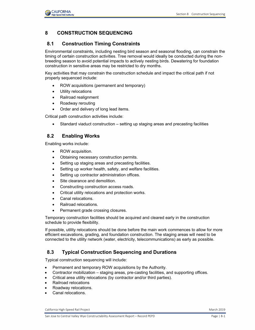
Section 8 Construction Sequencing
California High‐Speed Rail Project March 2019
San Jose to Central Valley Wye Constructability Assessment Report – Record PEPD Page | 8‐1
8 CONSTRUCTION SEQUENCING
8.1 Construction Timing Constraints
Environmental constraints, including nesting bird season and seasonal flooding, can constrain the timing of certain construction activities. Tree removal would ideally be conducted during the non-breeding season to avoid potential impacts to actively nesting birds. Dewatering for foundation construction in sensitive areas may be restricted to dry months.
Key activities that may constrain the construction schedule and impact the critical path if not properly sequenced include:
ROW acquisitions (permanent and temporary)
Utility relocations
Railroad realignment
Roadway rerouting
Order and delivery of long lead items.
Critical path construction activities include:
Standard viaduct construction – setting up staging areas and precasting facilities
8.2 Enabling Works
Enabling works include:
ROW acquisition.
Obtaining necessary construction permits.
Setting up staging areas and precasting facilities.
Setting up worker health, safety, and welfare facilities.
Setting up contractor administration offices.
Site clearance and demolition.
Constructing construction access roads.
Critical utility relocations and protection works.
Canal relocations.
Railroad relocations.
Permanent grade crossing closures.
Temporary construction facilities should be acquired and cleared early in the construction schedule to provide flexibility.
If possible, utility relocations should be done before the main work commences to allow for more efficient excavations, grading, and foundation construction. The staging areas will need to be connected to the utility network (water, electricity, telecommunications) as early as possible.
8.3 Typical Construction Sequencing and Durations
Typical construction sequencing will include:
Permanent and temporary ROW acquisitions by the Authority. Contractor mobilization – staging areas, pre-casting facilities, and supporting offices. Critical area utility relocations (by contractor and/or third parties). Railroad relocations Roadway relocations. Canal relocations.

Section 8 Construction Sequencing
March 2019 California High‐Speed Rail Project
8‐2 | Page San Jose to Central Valley Wye Constructability Assessment Report – Record PEPD
Hydraulic crossings. Wildlife crossings. Berm construction. Demolition of buildings and roadway structures. Roadway overcrossing structures. Roadway modifications. HSR at-grade earthwork construction. HSR retained fill construction. HSR viaduct construction (standard and non-standard). Demobilization.
A preliminary version of the project contract schedule that will be provided in the environmental documentation can be found in Appendix E. This version is subject to change.

Section 9 Traffic Control and Detours
California High‐Speed Rail Project March 2019
San Jose to Central Valley Wye Constructability Assessment Report – Record PEPD Page | 9‐1
9 TRAFFIC CONTROL AND DETOURS
Impacts to traffic must be minimized during construction and efficient movement through and around construction zones must be maintained throughout the duration of the construction. Extensive coordination with Caltrans, UPRR, and cities will be required. Detours allow for the most expeditious approach to completing the construction; however, they can cause public relation concerns within local communities. Detours require that current studies are performed to determine traffic volumes and movements that will be affected. Also, signal timing for proposed detour routes will need to be evaluated and signal phasing at intersections along detour routes will need to be adjusted to accommodate the new traffic volumes. Detour durations must be held to a minimum to avoid prolonged disruption to the traveling public. These are analyzed in further detail in the Environmental Transportation Technical Report.
9.1 At-Grade Crossing Replacement
The Blended At-Grade Alternative 4 will require reconstruction of a number of existing grade crossings between Santa Clara and Gilroy to accommodate shifted and new tracks.
Trackwork will be predominantly performed at night and on weekends, requiring short term roadway closures and establishment of roadway detours while roadway approach grading and paving is performed and new crossing panels are set. Crossing protection will be maintained through all phases of construction. Minor track work changes may be accomplished with temporary crossings permitting vehicular crossings between work shifts.
9.2 Monterey Corridor Grade Separations
For the grade separations required in the Monterey corridor, an assumed general approach is as follows:
Close the crossing street, reduce the number of travel lanes on Monterey Road, and shift traffic to construct a portion of the new roadway including structures.
Shift reduced number of travel lanes on Monterey Road to a newly constructed portion and complete the construction of the new roadway.
Restore Monterey Road traffic to the new permanent roadway alignment and connect the crossing street.
Complete the construction of HSR and UPRR alignments including structures to finish the grade separation.
For the grade separations required in the Morgan Hill and Gilroy corridors an assumed general approach is as follows:
Install temporary roadway detours as necessary.
Construct the HSR and UPRR embankment and structures (including UPRR shoofly tracks).
Construct portions of new grade separated roadways. Temporarily reduce and shift travel lanes. Roadway closures will be evaluated in aggregate so appropriate detours are available.

Section 9 Traffic Control and Detours
March 2019 California High‐Speed Rail Project
9‐2 | Page San Jose to Central Valley Wye Constructability Assessment Report – Record PEPD
9.3 Caltrain Station Access
There are six existing Caltrain stations that will need to remain in service during construction.
Caltrain Capitol Station
The existing Caltrain Capitol Station is in UPRR ROW under the dedicated HSR alignment viaduct as the alignment transitions from the west to the east side of the transportation corridor. To ensure public safety, the construction of the viaduct over the existing station would require either falsework over the station should the construction be done with CIP methods or the relocation of the station to the south should the construction be done with precast segments.
For the relocation option, we have developed an alternate location approximately 500 feet south of the existing station. This relocated station would be accessed using the existing Caltrain parking lot at Fehren Drive using the existing sidewalk on the east side of Monterey Road. A new mid-block, signalized pedestrian crossing would be constructed to access the station on the west side of Monterey Road. This relocated station could be either temporary or permanent since it is located outside of the construction area required for the HSR viaduct.
Caltrain Tamien, Blossom Hill, Morgan Hill, San Martin, and Gilroy Stations
The Tamien Station would remain in service and not require relocation. The Blossom Hill, Morgan Hill, San Martin, and Gilroy stations would be temporarily relocated so existing parking and access can be maintained. These relocations will be in conjunction with the UPRR shooflies associated with the at-grade alternative. The station relocations will need to be coordinated with the VTA as they operate and maintain them.
Additionally, roadway construction will impact local transit (non-rail) facilities, such as bus services, that will need to remain operational throughout construction. Temporary facilities will be provided (e.g. temporarily relocated bus routes and stops) with consideration for key transit locations and will be factored into the overall temporary traffic handling measures.
Traffic control features, such as construction signs and pavement makings, must be installed and maintained per current California Manual on Uniform Traffic Control Devices (CAMUTCD) Standards. Clearly identified construction zones and associated hazards must be in place prior to commencement of any construction activities to warn the traveling public and avoid potential liability claims. All traffic control measures must be reviewed twice daily, once at night and once during the daytime. Reports documenting all devices in use and the current status of the devices must be completed and submitted to the Design-Build team so deficient items can be immediately corrected.
To avoid logistical inconveniences for both construction crews and for the public, movements of materials and equipment will be made using the HSR ROW wherever practical.
Local and interstate highways will be affected by the movement of materials and equipment, and the contractor will be required to develop a Construction Transportation Plan to minimize this impacts. This plan will address in detail the activities to be carried out in each construction phase while maintaining traffic flow during peak travel periods. Such activities include, but are not limited to, the route and schedule for material deliveries, material staging and storage areas, construction employee arrival and departure schedules, employee parking locations, and temporary road closures, if needed. The plan will provide traffic controls pursuant to the CAMUTCD sections on temporary traffic controls (Caltrans 2014) and will include a traffic control plan.
Major construction traffic components are as follows:
Import of construction materials, such as: o Fuel, oil o Watero Concrete o Steel

Section 9 Traffic Control and Detours
California High‐Speed Rail Project March 2019
San Jose to Central Valley Wye Constructability Assessment Report – Record PEPD Page | 9‐3
o Cement o Aggregates o Fill material
Mobilization/demobilization of equipment.
Daily movements of craft labor.
Export of earth or other unsuitable materials.
Planned traffic detours and modifications to existing traffic flows will be required for the construction of roadway overpasses and for periodic hauling operations.
For safety, security, and logistics reasons, this ROW area will be fenced, and access will be controlled. Access to the site will be via specific gates along the ROW that will be strategically located with easy access to roads and freeways.


Section 10 Construction Pollution Control
California High‐Speed Rail Project March 2019
San Jose to Central Valley Wye Constructability Assessment Report – Record PEPD Page | 10‐1
10 CONSTRUCTION POLLUTION CONTROL
Dust, chemicals, noise, and vibration generated from the construction will pose significant concerns to the local communities. Control measures will be established to regulate these according to the mitigation and permit requirements outlined in the Environmental Impact Report/Environmental Impact Statement (EIR/S).
10.1 Air Quality
Air quality mitigation measures and permit requirements will be detailed in the EIR/S and will include:
Wet down stockpiles and areas of incomplete construction for road beds and tracks.
Dust palliative application.
Provide soil tracking devices to remove dirt build-up on construction equipment tires at access points to construction. Soil devices would consist of broken rock and/or rubble placed on filter fabric to vibrate off loose mud and dirt.
Provide street cleaning equipment.
Provide temporary sediment barriers.
10.2 Noise and Vibration
The noise and vibration limits chosen for construction and operation of the HSR System satisfy the federal guidelines of the FRA and Federal Transit Administration (FTA) for trains and HSR facility operations and Federal Highway Administration (FHWA) as defined for California application by Caltrans for traffic noise.
During construction, some equipment, most notably pile driving equipment, may cause ground-borne vibrations. Pile-driving is only one of the several proposed construction methods, and it is only expected to occur where there is the need for a bridge, aerial structure, or road crossing. Construction equipment can produce vibration levels at 25 feet that range from 58 vibration decibels (VdB) for a small bulldozer to 112 VdB for a pile driver. With pile driving, there is potential for severe vibration impacts during construction that would have substantial intensity under the National Environmental Policy Act (NEPA) and would be significant under the California Environmental Quality Act (CEQA). Without pile driving, the impact would have moderate intensity under NEPA and would be less than significant under CEQA.
Mitigation measures and permit requirements for noise and vibration levels will be detailed in the EIR/S and will include:
Restrict certain activities such as pile driving and hauling of borrow material to daytime operations only.
Provide sound walls around generators and other stationary equipment.
Monitor noise levels to ensure proper measures are taking place.
Perform vibration and settlement monitoring.
Cease operations with excessive vibration and evaluate alternative construction methods.
10.2.1 Water Quality
Water quality mitigation measures and permit requirements will be detailed in the EIR/S and will include:
Prepare and adhere to approved Stormwater Pollution Prevention Plan (SWPPP).
Comply with water quality permits (401/WDRs, 402, 404, dewatering)


Section 11 Construction Permits
California High‐Speed Rail Project March 2019
San Jose to Central Valley Wye Constructability Assessment Report – Record PEPD Page | 11‐1
11 CONSTRUCTION PERMITS
All construction permits must be obtained before starting construction. The Contractor must identify what permits will be necessary for the construction, ROW, easements, environmental protection, etc. for contract execution.
Below is a preliminary list of anticipated permits that may need to be acquired:
Table 11-1 Construction Permits
Jurisdiction Potential Permit Required
California Department of Water Resources Encroachment Permit
California Public Utilities Commission Authority to Construct
Caltrain/Peninsula Corridor Joint Powers Board (PCJPB)
Right-of-Entry Survey Permit
Central Valley Flood Protection Board Encroachment Permit
City of Gilroy Building Permit, Encroachment Permit, Maintenance Agreement, Memorandum of Understanding (MOU)
City of Morgan Hill Building Permit, Encroachment Permit, Maintenance Agreement, MOU
City of San Jose Building Permit, Encroachment Permit, Flood Hazard Zone, Geological Hazard Clearance, Grading & Erosion Control, Maintenance Agreement, MOU, Utility Permit
County of Merced Building Permit, Construction Detours, Encroachment Permit, Environmental Health Permit, Maintenance Agreement, MOU
County of San Benito Maintenance Agreement, MOU, Encroachment Permit
County of Santa Clara Building Permit, Encroachment Permit, Maintenance Agreement, MOU
Irrigation and Water Districts:
See Hydrology and Hydraulics Report – PEPD
Encroachment Permit, Maintenance Agreement, MOU
Pajaro River Watershed Flood Prevention Authority
MOU
RWQCB, Central Coast Region 3 NPDES permit
RWQCB, Central Valley Region 5 NPDES permit
RWQCB, San Francisco Bay Region 2 NPDES permit in association with SWPPP
Santa Clara Valley Transportation Authority Construction Access Permit, Restricted Access Permit
South County Airport Encroachment Permit
Union Pacific Railroad Right-of-Entry Survey Permit
United States Bureau of Reclamation Encroachment Permit, Construction Access Permit, Maintenance Agreement

Section 12 Third Party Coordination and Agreements
California High‐Speed Rail Project March 2019
San Jose to Central Valley Wye Constructability Assessment Report – Record PEPD Page | 12‐1
12 THIRD PARTY COORDINATION AND AGREEMENTS
12.1 Caltrans
The project crosses Caltrans property and facilities at numerous locations, and the San Jose to Merced section crosses Caltrans Districts, 4, 5 and 10. Throughout the HSR facilities construction, regardless of the alignment chosen from San Jose to Merced, the rail construction will require a working relationship with Caltrans and a binding agreement.
Prior to construction, an interagency agreement(s) between Caltrans and the Authority would clearly identify the agreements made for both the construction and ongoing operations and maintenance of both rail and highway facilities.
In this interagency agreement(s), the joint use of ROW with the rail either under or over Caltrans highway facilities needs to be accurately defined. Once defined, it must be recorded with the State of California State Lands Commission pursuant to the provisions of Section 101.5 of the Streets and Highway Code.
The impact of the rail construction on Caltrans facilities and highway traffic must be evaluated which should include, but is not limited to, the resulting change in the seismic safety of the highway structures. The change may occur from modified earthwork around bridge columns or abutments. If the highway structure is affected by the rail construction, the correctional mitigations should be included in the rail construction bid documents.
For the HSR project, it is possible several Caltrans divisions would be involved in developing an interagency agreement and conflicting recommendations are possible. Caltrans headquarters in Sacramento oversees the legal aspects of any agreement and typically gives final approval. Development of a typical agreement with Caltrans takes several months, so this agreement could take years to finalize due to the complexity of the agreement and the decision-making structure.
During development of the interagency agreement(s), there may issues that will arise. Since the design is not yet fully developed, the following issues are most likely not the only ones that may be experienced, but they provide a basic understanding of issues that have arisen in the past:
Caltrans has required that structures built over state highways be built to Caltrans specifications.
Design of a structure spanning a state highway could require multiple reviews by the Caltrans Bridge Department.
Erection of the structure over the state highway will be dictated by Caltrans. Seven to ten locations will require rail line construction below a Caltrans bridge structure.
Design of Caltrans bridges has been performed using planned site conditions.
Planned rail construction can affect state highway ancillary facilities.
Active construction under a Caltrans structure will pose several concerns for Caltrans and the agency will demand an oversight role.
Address the future maintenance responsibilities for the project’s constructed facilities and maintenance of the joint ROW in a section of the agreement.
12.2 Utilities
Constructability will be affected by the presence, characteristics, and handling of utilities within the project. Handling includes planning and executing both temporary and permanent changes to utility configuration. Each utility crossing that will be affected should be the subject of a definitive plan for construction. Utilities, being predominantly placed underground, are often the subject of claims for unforeseen conditions. Contractors also lodge claims when utility companies fail to act promptly and cause delay to the contractor’s progress.
Section 12 Third Party Coordination and Agreements
March 2019 California High‐Speed Rail Project
12‐2 | Page San Jose to Central Valley Wye Constructability Assessment Report – Record PEPD
Utility companies possess certain rights to have and maintain facilities in easements within the HSR construction area, including in Caltrain, UPRR, Caltrans, and other local agency ROW and in the overall project vicinity. Utilities services must be kept in continuous operation except for short and well-planned outages related to cutovers and emergency repairs. For purposes of this discussion, a utility in the ROW is any non-railroad pipeline, conduit, channel, or other conveyance, including electrical or telecommunications.
In some cases, utility companies may own rights via easements, licenses, and permits to use property even where they do not have existing physical facilities. In nearly every case where utilities lines exist in the ROW they are subject to being moved and altered to accommodate the new construction of the HSR project. ROW expansion will encompass utilities that are not currently in the ROW.
The mutual duties established between the Authority, as project Owner, with each utility should be recorded in formal agreements that provide guidelines for what work is to be done, by whom, when, and how.
City and county jurisdictions operate utility enterprises as financial entities distinct from their general funds. Some utilities, notably telecommunications, may run in joint facilities such as duct banks and trenches. Relocation of these facilities requires multi-party negotiation and coordination that be time-consuming as various parties review proposals by others. Utilities sharing facilities may also have different design standards that can conflict with each other and require resolution.
Relocation of utilities that make use of the ROW for conveyance (longitudinal utilities) may require extensive design, including temporary relocations and tie-ins. These utilities may include telecommunications, electrical power, fuel and gas pipelines, and others.
The construction drawings should have detailed and accurate depictions of the utilities in the project vicinity. It is important to pothole critical utilities to assure the utilities are where they are believed to be.
12.3 Railroads
12.3.1 Caltrain
Constructability will be affected by the timeliness and provisions of agreements made with the PCJPB, which operates commuter rail service along the San Francisco Peninsula, through the South Bay to San Jose and Gilroy and maintains various systems and safety operations. PCJPB owns the ROW north of CP Lick.
Under the blended system concept, the HSR will operate using the same main tracks as Caltrain trains north of Diridon Station (or north of Gilroy under Alternative 4), so the HSR project will require thorough and detailed coordination of design, systems integration, construction planning, construction coordination, operational testing, and operations when HSR is in service.
Construction of the PCJPB Caltrain Modernization (CalMod) Project is expected to precede the HSR project. CalMod will install electrification and controls systems that will be compatible with and jointly used with HSR. When HSR is put into operation, Caltrain will exercise central control over the system including HSR trains.
New turnouts, switches, crossovers, and other installations on the existing main track will require several hours of train outages. Without agreed-on regular days and hours of operational outages, bidders will be unable to provide realistic bids and would most likely increase their bids to account for scheduling uncertainty.
Without detailed and mutually agreeable policies and procedures for joint usage of track areas during construction, HSR contractors will face unexpected and unscheduled interruptions in work causing delays and extra cost. Before construction, it is important to establish thorough and complete plans for site safety coordination in the form of a Project Safety Plan that is reviewed and interactively worked out with Caltrain. During construction, the team should practice joint

Section 12 Third Party Coordination and Agreements
California High‐Speed Rail Project March 2019
San Jose to Central Valley Wye Constructability Assessment Report – Record PEPD Page | 12‐3
planning for specific work through Site Specific Work Plans, and investigate and troubleshoot any and all failures of safety planning, communication, and execution.
It will be important to establish a joint operations safety board including representatives of Caltrain, UPRR, Authority construction managers, and contractors that meets regularly and confines its discussion to operations and safety. The board will disseminate lessons-learned to project participants and the Authority for general distribution.
12.3.2 Union Pacific Railroad
Constructability will be affected by the timeliness and provisions of agreements made with UPRR. North of CP Lick, UPRR has retained certain rights for use of the Caltrain ROW that include revenue-producing ownership of utility easements and operation of freight rail trains. HSR construction will require that UPRR’s utility easements be altered or bought to allow both temporary and permanent relocation. Our investigation of rail conditions and spurs indicates that a low volume of freight traffic runs along the Caltrain ROW; however, the Authority should expect UPRR to defend any ROW rights they possess vigorously. South of CP Lick, UPRR owns the ROW which Caltrain operates on. In areas both north and south of CP Lick, the construction of HSR will result in numerous impacts to the Caltrain and UPRR ROW. Negotiations with UPRR can be protracted and difficult.
HSR construction will require UPRR agreement and cooperation in five areas:
1. Freight Operations Schedule – Without agreed upon days and hours of operation by UPRR in this corridor, the contractor will be unable to provide a realistic bid and would most probably increase his bid to account for uncertainty.
2. Freight Operations Accessibility – Maintaining continuous access to spurs, sidings, and junctions during construction will be important to UPRR.
3. Material Transportation – An umbrella agreement would stabilize freight pricing in advance of bidding, giving contractors reliable costs and ground rules. Negotiation of prices and terms by the Authority could also be advantageous to the project by offering UPRR motivation to cooperate on other issues.
4. Using Off-Route Right-of-Way – It may be advantageous for the Authority to use UPRR ROW outside the HSR/Caltrain route as paths for non-rail methods of material movement. These could include spur tracks at Quint Street in San Francisco, the junction leading to the old Dumbarton railroad bridge, and the Milpitas and Oakland Subdivisions.
5. Utilities Relocation – Some UPRR-owned third-party easements will have to be relocated or purchased by HSR or Caltrain to accommodate construction.
It is recommended that the Authority complete a full and accurate study to identify all utilities running in the Caltrain ROW, conduct multi-party negotiation, and finalize multilateral binding agreements that will provide the basis for utilities relocations into new easements and for interim relocations appropriate for staging during construction process.
12.4 Local Jurisdictions
12.4.1 Discussion
The JM Section of the HSR route passes through three cities, three counties, and several unincorporated areas. Contractors will need to access the HSR site through these jurisdictions. Issues, including utility relations, street conforms, property takes, and many others will need to be agreed upon preferably before awarding contracts. Prior to a construction bid, detailed agreements with jurisdictions would fully inform and formalize the project’s proposed construction details, environmental mitigations, and operating parameters.
Municipal codes and policies will vary in each jurisdiction affecting rules involving working hours, haul routes, noise, and other factors in construction. Failure to obtain binding and detailed legal

Section 12 Third Party Coordination and Agreements
March 2019 California High‐Speed Rail Project
12‐4 | Page San Jose to Central Valley Wye Constructability Assessment Report – Record PEPD
agreements with the local jurisdictions will result in possible additional project costs and delays. Uncooperative cities and counties have the power to close haul routes, restrict traffic movements, restrict movement of oversize loads, and place weight limits on streets necessary for import and export of material.
Cities and counties may have locally-owned utilities that will be affected by the rail construction. These often include sewer, storm drain, and traffic signal conduits. The protection or rerouting of these utilities where they are affected needs to be detailed in the agreement, including who will be responsible for the work and how payment will be made if the city or county does the required work. Since both sewer and storm drainage systems rely on gravity for flow, the utility relocation or protection cost could be extensive, requiring rerouting or, in some cases, pump stations.
The following are some of the most important local construction work concerns that should be included in the local agency agreements.
Building Permits
Haul Routes and Traffic
Street Closures
Work Hours
Use of City Standards
Dust, Air Pollution, and Odor Control
Sound Control
Project Appearance
12.5 Coordinating Betterments and Adjoining Third Party Work
12.5.1 Discussion
Constructability will be affected by work the Authority agrees to undertake on behalf of other agencies and stakeholders. For instance, a city may wish to increase the size of a sewer pipeline crossing the right-of-way that must be rerouted to clear a bridge footing. Since the increase in pipe size is mandated by its sewer master plan, the cost difference between the smaller and the larger pipe would be paid by the city because the Authority is responsible for a replacement not a better facility.
Likewise, any major project is often accompanied by work done by other agencies and adjoining landowners at that stakeholder’s expense. Although this can be referred to as “adjoining work”, in some cases this work takes place within the HSR project limits. Both kinds of work are prone to disagreements on cost and can affect the schedule.
The construction agent (i.e., the stakeholder’s design and construction representative) for this work may be the Authority through a negotiated agreement, a stakeholder, or another party. Many betterments are best incorporated into contracts for the major project for unified coordination of the schedule and budget.
A good interagency C&M agreement must be thorough and clear about the financial responsibility for all betterments, and the costs should be agreed on prior to beginning work. In a design-build contract without unit price bids, this will be difficult, but better than after the work is performed when it could not be modified. Agreements should provide for additional payment to HSR for price escalation, unforeseen conditions, and other possible occurrences that increase costs.

Section 13 Potential Excavation Hazards
California High‐Speed Rail Project March 2019
San Jose to Central Valley Wye Constructability Assessment Report – Record PEPD Page | 13‐1
13 POTENTIAL EXCAVATION HAZARDS
13.1 Surface Soils
The project area is underlain by sedimentary soils from the surface to a depth below the likely depth of project excavations. Soils include combinations of sands, gravel, cobbles, silts, and clays. Granular soils can “run”, pouring from excavation surfaces and creating instability. Fine sands can also be saturated with water and be difficult to compact without using methods to drain the water or chemically stabilize them with cement or lime. These conditions should be expected and provisions made in the contract documents for remedies.
13.2 Deep Excavations
With deep excavation, the contractor is likely to encounter site conditions that differ from those depicted in the contract documents. Groundwater may also differ from what is shown in soil borings. Differing site conditions often result in disputes and then change orders or claims. Deep cuts will require that soft native soils be shored and reinforced to avoid settlement of soil structures. Groundwater intrusion and settlement can be minimized by specifying the means of shoring at the trench boundaries to create a water seal that keeps drawdown at a minimum in areas adjoining the trenches. These might include overlapping drilled piers, slurry walls, and watertight sheetpile walls.
In the project area, the water table can be high enough to seep into excavations, requiring collection and disposal of groundwater. Flowing groundwater can cause settlement in the ground above drawn-down soil volumes. Also, the groundwater may include contaminants and its disposal may require treatment and/or costly disposal. Likely contaminants and volumes to be disposed should be estimated and methods of disposal agreed upon before beginning construction.
Reinforcing methods such as anchors or soil nailing may require ROW actions be taken when they will be placed under adjoining properties. A survey of engineering solutions to prevent ground movement should be undertaken early in the 30% design phase when the final railroad alignment is determined, , including a constructability review and a detailed estimation of probable costs to serve as a decision-making guide for the most appropriate methods.
Some of the areas adjacent to the project are densely populated with residential and commercial structures that could sustain damage if the ground under them subsides or moves laterally. A pre-construction condition survey should be performed to document the condition of adjacent properties.

Section 14 Right‐of‐Way Acquisition
California High‐Speed Rail Project March 2019
San Jose to Central Valley Wye Constructability Assessment Report – Record PEPD Page | 14‐1
14 RIGHT-OF-WAY ACQUISITION
The Authority plans to acquire all needed ROW including TCEs prior to the start of construction. Property acquisition for the HSR section from San Jose to Central Valley Wye will involve over 1,000 parcels for each of the alternatives. Under rules and statutes, both State and federal, acquisition of property is time-consuming and not predictable regarding method or timeliness. Properties that will have to be acquired include private properties, state and local ROW, and utility property.
HNTB gathered existing ROW information from the counties within this section from digital assessor’s parcel map data, including the assessor’s parcel number and the parcel size. ROW and parcel boundaries, parcel information, and HSR footprint were displayed in GIS format, and the areas of acquisition and remnant and excess parcels were calculated.
Most parcels will require a partial acquisition of their total area resulting in a remnant that is not needed for the project. In some cases, a full acquisition of the parcel was determined to be necessary. This will be the case if the Regional Consultant (RC) observed that either (a) the remainder is not a viable economic unit that retains its highest and best use or (b) the impact to remaining land and improvements is too great to continue to function. In other cases, damages to an area of a parcel were determined to be necessary. An area was classified to be damaged if the RC observed that there will be no legal access, in addition to the criteria used for full acquisitions.
Property acquisition for HSR has occurred already in Merced, Fresno, Kings, and Kern counties. Lessons learned from this process are expected to help establish and improve HSR guidelines and practices for property acquisition.
Failure to acquire ROW for the project will delay both the start and the progress of construction. If construction is commenced without cleared ROW, it is most likely to result in costly ROW delay claims and an overall project delay. Because of the significant amounts of ROW that must be acquired, there is a risk that a lack of qualified ROW engineers, appraisers, title professionals, and acquisition staff will result in project delay.
In the past, taking too many properties has caused a backlash of public opinion and resulted in more restrictive and time-consuming ROW practices which would further slowdown the acquisition process.
Property acquisition from UPRR and other governments can be lengthy. If acquisition work on those properties is not started early, these difficult properties will delay the project.
ROW acquisition will likely be on the critical path for those segments that have numerous properties to acquire before starting construction. When prioritizing construction projects, it may be wise to select the segments with more challenging acquisitions.
As soon as an option is decided on and approved, negotiations with cities and counties for their properties needed for the rail construction and operation should begin. See Section 12.4 Local Jurisdictions. Also, negotiations should begin with each identified utility that will be affected by the project. These negotiations would include the party performing utility relocation or protection, when the relocation would be accomplished, and who would be paying for the required work. See Section 12.2 Utilities.

Section 15 Construction Pollution Control
California High‐Speed Rail Project March 2019
San Jose to Central Valley Wye Constructability Assessment Report – Record PEPD Page | 15‐1
15 CONSTRUCTION POLLUTION CONTROL
Hazardous Materials – Portions of the project area has been in use for decades for transportation, industrial, and commercial purposes. The soil in numerous locations has accumulated pollutants, some of which may have been deposited or migrated to the project area in groundwater.
Contaminated materials that must be removed or may be reused by the project will need to be retested for disposal or reuse to assure that disposal or reuse is proper and legal. The soil adjacent to operating rails is often contaminated with either lead or petroleum products. Some of the material from the abated structures and contaminated soils may require removal to a Class 1 landfill. For California, this type of material is usually transported to Kettleman City or Coalinga —about 200 miles southeast of the project. Cost of the disposal is high at the Class 1 landfills and the Authority could have future costs from the Class 1 landfill disposal since generators are held responsible for the materials in perpetuity.
In the San Francisco Bay Area, there are specialty contractors that undertake abatement of toxic materials and obtain regulatory permits to clear the property. These specialty contractors can either work as prime or subcontractors for the prime rail contractor.
Noise and Vibration – Construction equipment and processes create noise and vibration that can affect nearby stakeholders in their residences, commercial establishments, work places, and outdoors. The EIS will provide an analysis of these effects and recommend mitigations in areas where noise/vibration effects are excessive. Construction contracts should require observation of mitigation measures and set performance standards. A pre-construction study of ambient conditions should be conducted to measures noise and document conditions in structures close enough to construction activities to be potentially damaged by vibrations.
Dust Control – Much of the project will take place near residential and commercial land uses. Contract documents should include stringent provisions requiring builders reduce dust emissions to a minimum.


Section 16 Conclusions
California High‐Speed Rail Project March 2019
San Jose to Central Valley Wye Constructability Assessment Report – Record PEPD Page | 16‐1
16 CONCLUSIONS
This phase of the San Jose to Merced Project Section project development does not lend itself to concrete technical conclusions and recommendations about constructability, project delivery, and contract packaging. Rather, this report focused on constructability issues that are appropriate to the current plan development stage.
We concluded that each of the four alternatives, as currently presented, can be built but they present varying degrees of complexity, cost, duration, and impact on the environment and the public. Physical and other constraints on each alternative will vary the expense, duration, and impact of each alternative.
Costly concerns that should be addressed in detail before the project is built include:
Property acquisition will be long and complex. The Authority should carry out property acquisitions itself and not delegate this to the design-build contractors.
Construction work should not begin on the route segment before all property acquisitions are completed.
Responsibility, processes, and payment mechanisms for dealing with unforeseen environmental contamination should be established in construction contract documents.
C&M agreements with stakeholders including local jurisdictions, Caltrans, and utilities should be comprehensive, detailed, and executed before beginning construction.
Reflect stakeholder agreements in the construction contract documents and bind contractors to perform in accordance with them.
Accommodation of Caltrain and UPRR train operations will constrain construction operations and increase the construction cost and duration.
At-grade and viaduct cross-sections are the most buildable cross-sections.
Trench and embankment cross-sections present the most difficult staging challenges mostly due to constrained ROW width, earthmoving operations, and difficulties stemming from keeping Caltrain, UPRR, and Caltrans operational without modification.
Identified laydown and staging areas are not large enough to efficiently support the work. Property acquisitions by the Authority will be needed to provide adequate areas.


Section 17 References
California High‐Speed Rail Project March 2019
San Jose to Central Valley Wye Constructability Assessment Report – Record PEPD Page | 17‐1
17 REFERENCES
Caterpillar. Caterpillar Performance Handbook. 38th ed. January 2008. Parsons. California High-Speed Train San Jose to Merced Section Draft Constructability Assessment Report. 2011. URS/HMM/Arup Joint Venture. PE4P Record Set Submission, Fresno to Bakersfield, Sierra Subdivision, Construction Package 4, Constructability Assessment Report. 2014. Pan, N-H., Tsung-Chih Chiu, Kuei-Yen Chen. Full-span Precast Launching Method (FPLM) Analysis with Dynamic Simulation – Case Studies of Taiwan High-Speed Rail (THSR) Project. Automation in Construction, 17:592-607. 2008.

Appendix A
California High‐Speed Rail Project March 2019
San Jose to Central Valley Wye Constructability Assessment Report – Record PEPD Page | A‐1
APPENDIX A: MONTEREY HIGHWAY VIADUCT, TYPICAL SECTION INSTALLATION – FULL SPAN PRECAST


Appendix B
California High‐Speed Rail Project March 2019
San Jose to Central Valley Wye Constructability Assessment Report – Record PEPD Page | B‐1
APPENDIX B: MONTEREY HIGHWAY VIADUCT, BALANCED CANTILEVER INSTALLATION


Appendix C
California High‐Speed Rail Project March 2019
San Jose to Central Valley Wye Constructability Assessment Report – Record PEPD Page | C‐1
APPENDIX C: MONTEREY HIGHWAY VIADUCT, PRECAST BOX GIRDER YARD DIMENSIONS


Appendix D
California High‐Speed Rail Project March 2019
San Jose to Central Valley Wye Constructability Assessment Report – Record PEPD Page | D‐1
APPENDIX D: SAN JOSE STATION APPROACH CONSTRUCTABILITY ANALYSIS

Appendix E
California High‐Speed Rail Project March 2019
San Jose to Central Valley Wye Constructability Assessment Report – Record PEPD Page | E‐1
APPENDIX E: POTENTIAL CONTRACT PACKAGES AND SCHEDULE


Appendix F
California High‐Speed Rail Project March 2019
San Jose to Central Valley Wye Constructability Assessment Report – Record PEPD Page | F‐1
APPENDIX F: POTENTIAL CONSTRUCTION SEQUENCE AT I-280


Appendix G
California High‐Speed Rail Project March 2019
San Jose to Central Valley Wye Constructability Assessment Report – Record PEPD Page | G‐1
APPENDIX G: POTENTIAL CONSTRUCTION SEQUENCE AT MONTEREY HIGHWAY

Appendix H
California High‐Speed Rail Project March 2019
San Jose to Central Valley Wye Constructability Assessment Report – Record PEPD Page | H‐1
APPENDIX H: TRACK SHIFT WORKS
