appendix 10, automation standard - sesam world€¦ · this document is addressed to sellers of ......
TRANSCRIPT

Arla IT MSA Arla Foods Group Appendix 10 Interface requirements and specifications for
Units - PackML
Version 01
Page 1 of 47
Seller ________
APPENDIX 10, Automation Standard to Arla Foods Group Agreement for Purchase of Machinery including installation
Interface requirements and Specification for Units - PackML
Arla IT MSA Arla Foods Group Appendix 10 Interface requirements and specifications for
Units - PackML
Version 01
Page 2 of 47
Seller ________
Version log Version Date Author Description of changes
01 2014-02-20 CAN First version.

Arla IT MSA Arla Foods Group Appendix 10 Interface requirements and specifications for
Units - PackML
Version 01
Page 3 of 47
Seller ________
Table of contents 1 Introduction ............................................................................................................................. 4
1.1 Purpose ........................................................................................................................... 4 1.2 Abbreviations & definitions ............................................................................................ 4 1.3 Mandatory and optional requirements .......................................................................... 6 1.4 Background ..................................................................................................................... 6
2 Understand the Control of a Unit ............................................................................................ 7 2.1 Interface Specification – One Interface State Model ...................................................... 7 2.2 Definition of a Unit .......................................................................................................... 8 2.3 The Control of a line and units ........................................................................................ 9 2.4 Digital I/O for synchronization of units ........................................................................... 9
3 The PackML Interface State Model ........................................................................................ 12 3.1 The Unit Conditions Matrix ........................................................................................... 15 3.2 PackML Control Commands .......................................................................................... 16 3.3 PackML Interface Unit State definition ......................................................................... 19 3.4 Unit Control modes ....................................................................................................... 23 3.5 Overall Equipment Effectiveness - OEE ......................................................................... 24
3.5.1 Data requirements for OEE calculation and other KPI‘s ........................................... 24 3.5.2 EventID ...................................................................................................................... 24 3.5.3 Detailed Error info .................................................................................................... 25 3.5.4 Product counter ........................................................................................................ 25 3.5.5 Relation between PackML state, PackML mode and OEE EventID .......................... 26
3.6 Warning and Error information .................................................................................... 27 3.6.1 Warning .................................................................................................................... 27 3.6.2 Error .......................................................................................................................... 27
3.7 Additional data .............................................................................................................. 27 4 Test requirements.................................................................................................................. 28 5 Software Design Specification requirements ........................................................................ 30
5.1 Communication topology .............................................................................................. 30 5.2 Ethernet communication .............................................................................................. 31
5.2.1 Obtain the data block structure................................................................................ 31 Communication DB data definition ............................................................................................ 33 5.3 Communication data ..................................................................................................... 34 5.4 Data Block: Heart Beat .................................................................................................. 35 5.6 Data Block: Mode & State ............................................................................................. 36 5.7 Data Block: Command ................................................................................................... 37 5.8 Data Block: Job data ...................................................................................................... 38 5.9 Data Block: OEE ............................................................................................................. 39 5.10 Data Block: Warning & Error ......................................................................................... 41 5.11 Data Block: Additional data ........................................................................................... 42
6 Special unit requirements ...................................................................................................... 44 6.1 Special issues related to printer device ........................................................................ 44 6.2 Special issues related to other types devices ............................................................... 45 6.3 Special issues to other devices ...................................................................................... 45
7 Optional requirements .......................................................................................................... 46 7.1 SafePLC and E-stop ........................................................................................................ 46

Arla IT MSA Arla Foods Group Appendix 10 Interface requirements and specifications for
Units - PackML
Version 01
Page 4 of 47
Seller ________
1 Introduction
This document is addressed to sellers of units to the Arla Foods Group. This document describes the requirements for a unit that a seller has to live up to. The base is that the production line is constructed with a Line Control. There may be cases where a Line Controller isn’t required. A unit can be a machine, packaging machine, and other types of units in a production line.
1.1 Purpose The purpose of this document is to give the requirements for implementing an Interface to a Unit. The Interface described in this document is built on international reference model PackML defined by The International Society of Automation (ISA). The interface follows the PackML State Model as described in Packaging Machine Language V3.0 Mode & States Definition Document (Reference ISA TR88.00.02.) published by the Packaging Machine Language (PackML) group within Organization for Machine Automation and Control (OMAC). This document describes Arla Foods Group implementation of PackML standard.
1.2 Abbreviations & definitions Abbreviation Description Explanation
EMS Effectiveness Management System
Buyer standard application for calculating and monitoring Overall Equipment Effectiveness, Line Efficiency and Mechanical Machine Efficiency.
ERP Enterprise Resource Planning
An ERP system is the company’s superior financial system, inventory control and planning system, etc.
CL Cleaning Planned stop for cleaning, CIP that is part of OEE calculation, and represents the time used on Clean In Process (CIP) and cleaning of equipment.
FAT Factory Acceptance Testing Test of the Equipment being carried out before delivery. The test is carried out to ensure that delivery is in accordance with stated requirements. Further reference is made to the Agreement.
HMI Human Machine Interface Human machine interface is the part of the unit that handles the human machine interactions.
I/O test Input / Output test I/O test is a test of electrical connection at place of installation.
ISA The International Society of Automation
ISA is a non-profit technical society for engineers, technicians, businesspeople, educators and students, who work, study or are interested in industrial automation and pursuits related to it.
LC Line Controller A controller that controls a number of units in a line. The line controller could be a PLC or part of existing PLC.
LE 1 LE 2
Line Efficiency LE is the Effectiveness only focusing on the Plant Production Time, which includes production Time, Quality Loss, Speed Loss and Down Time Loss.
LF Line Failure – external stops Part of OEE calculation, and represents the time where a unit is stopped because of external conditions. For example saturation or starvation.
Table 1: Abbreviations & definitions
Arla IT MSA Arla Foods Group Appendix 10 Interface requirements and specifications for
Units - PackML
Version 01
Page 5 of 47
Seller ________
Abbreviation Description Explanation
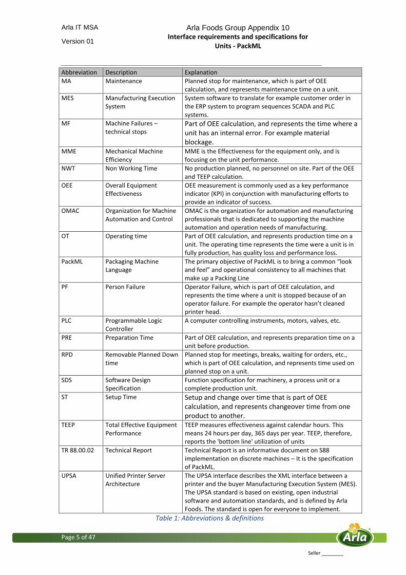
MA Maintenance Planned stop for maintenance, which is part of OEE calculation, and represents maintenance time on a unit.
MES Manufacturing Execution System
System software to translate for example customer order in the ERP system to program sequences SCADA and PLC systems.
MF Machine Failures – technical stops
Part of OEE calculation, and represents the time where a unit has an internal error. For example material blockage.
MME Mechanical Machine Efficiency
MME is the Effectiveness for the equipment only, and is focusing on the unit performance.
NWT Non Working Time No production planned, no personnel on site. Part of the OEE and TEEP calculation.
OEE Overall Equipment Effectiveness
OEE measurement is commonly used as a key performance indicator (KPI) in conjunction with manufacturing efforts to provide an indicator of success.
OMAC Organization for Machine Automation and Control
OMAC is the organization for automation and manufacturing professionals that is dedicated to supporting the machine automation and operation needs of manufacturing.
OT Operating time Part of OEE calculation, and represents production time on a unit. The operating time represents the time were a unit is in fully production, has quality loss and performance loss.
PackML Packaging Machine Language
The primary objective of PackML is to bring a common “look and feel” and operational consistency to all machines that make up a Packing Line
PF Person Failure Operator Failure, which is part of OEE calculation, and represents the time where a unit is stopped because of an operator failure. For example the operator hasn’t cleaned printer head.
PLC Programmable Logic Controller
A computer controlling instruments, motors, valves, etc.
PRE Preparation Time Part of OEE calculation, and represents preparation time on a unit before production.
RPD Removable Planned Down time
Planned stop for meetings, breaks, waiting for orders, etc., which is part of OEE calculation, and represents time used on planned stop on a unit.
SDS Software Design Specification
Function specification for machinery, a process unit or a complete production unit.
ST Setup Time Setup and change over time that is part of OEE calculation, and represents changeover time from one product to another.
TEEP Total Effective Equipment Performance
TEEP measures effectiveness against calendar hours. This means 24 hours per day, 365 days per year. TEEP, therefore, reports the 'bottom line' utilization of units
TR 88.00.02 Technical Report Technical Report is an informative document on S88 implementation on discrete machines – It is the specification of PackML.
UPSA Unified Printer Server Architecture
The UPSA interface describes the XML interface between a printer and the buyer Manufacturing Execution System (MES). The UPSA standard is based on existing, open industrial software and automation standards, and is defined by Arla Foods. The standard is open for everyone to implement.
Table 1: Abbreviations & definitions
Arla IT MSA Arla Foods Group Appendix 10 Interface requirements and specifications for
Units - PackML
Version 01
Page 6 of 47
Seller ________
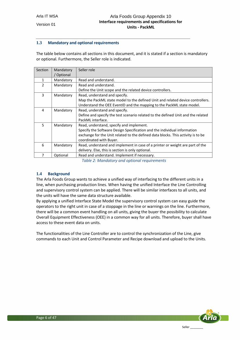
1.3 Mandatory and optional requirements The table below contains all sections in this document, and it is stated if a section is mandatory or optional. Furthermore, the Seller role is indicated. Section Mandatory
/ Optional Seller role
1 Mandatory Read and understand.
2 Mandatory Read and understand. Define the Unit scope and the related device controllers.
3 Mandatory Read, understand and specify. Map the PackML state model to the defined Unit and related device controllers. Understand the OEE EventID and the mapping to the PackML state model.
4 Mandatory Read, understand and specify. Define and specify the test scenario related to the defined Unit and the related PackML interface.
5 Mandatory Read, understand, specify and implement. Specify the Software Design Specification and the individual information exchange for the Unit related to the defined data blocks. This activity is to be coordinated with Buyer.
6 Mandatory Read, understand and implement in case of a printer or weight are part of the delivery. Else, this is section is only optional.
7 Optional Read and understand. Implement if necessary.
Table 2: Mandatory and optional requirements
1.4 Background The Arla Foods Group wants to achieve a unified way of interfacing to the different units in a line, when purchasing production lines. When having the unified Interface the Line Controlling and supervisory control system can be applied. There will be similar interfaces to all units, and the units will have the same data structure available. By applying a unified Interface State Model the supervisory control system can easy guide the operators to the right unit in case of a stoppage in the line or warnings on the line. Furthermore, there will be a common event handling on all units, giving the buyer the possibility to calculate Overall Equipment Effectiveness (OEE) in a common way for all units. Therefore, buyer shall have access to these event data on units. The functionalities of the Line Controller are to control the synchronization of the Line, give commands to each Unit and Control Parameter and Recipe download and upload to the Units.

Arla IT MSA Arla Foods Group Appendix 10 Interface requirements and specifications for
Units - PackML
Version 01
Page 7 of 47
Seller ________
2 Understand the Control of a Unit
2.1 Interface Specification – One Interface State Model The interface describes an Interface State Model for the unit in relation to the handling and exchange of data, and the control of the unit. The unit can be controlled by an existing Machine State Model. The internal States shall be mapped to the Interface State Model described in this document. This means that the seller needs to define when the Physical Unit is in a given Interface State, and also how the Physical Unit receives commands via the interface (Start, Stop, etc.).
Figure 1: One interface state model A unit must be able to handle two different modes: Producing mode & Manual mode Mode Description
Producing In producing mode, all control and data communication to the unit goes through this PackML interface. Collecting OEE data is only performed in Producing mode.
Manual In manual mode it is possible for the operator to control the unit form the units local HMI.
Table 3: Modes on the unit

Arla IT MSA Arla Foods Group Appendix 10 Interface requirements and specifications for
Units - PackML
Version 01
Page 8 of 47
Seller ________
2.2 Definition of a Unit A unit is functionally or physically linked together through a common unit controller. A unit is having from a communication point of view, one interface in relation to the operation of the unit from an external control system. An error on a unit will stop all the subsystems within the unit. If an error on a unit only stops part of the subsystems, the individual subsystem is to be defined as an individual unit. It is up to the seller to define the mapping of the PackML interface to the physical unit and the internal control systems. For example, a Unit can have 3 internal drive controllers but is perceived as one unit from a user situation and operator access.
Figure 2: Different types of units and their mapping to the one PackML interface There are some special situations where the seller needs to be carefully in the definition of a unit. These situations are: Conveyer: It is to be decided which unit is controlling the upstream and downstream conveyer between two units. The conveyer can also be a unit on its own, when then conveyer has its own control system. Printer: A unit might include a printer, and then it is important to evaluate if the printer within the units needs a separate printer server. For further information see section 6.1. Scale: The scale is similar to the print setup. If the weight needs a separate weight data for E-weight or weight logging, a special weight setup is required. For further information see section 6.2.

Arla IT MSA Arla Foods Group Appendix 10 Interface requirements and specifications for
Units - PackML
Version 01
Page 9 of 47
Seller ________
2.3 The Control of a line and units The Line Controller handles the control and coordination between the units in a line. The only data communication each unit has, is with the Line Controller. The seller will mainly have to cooperate with a software engineer appointed by the buyer who takes care of the Line Control.
Figure 3: Control og units form a Line Controller The communication of data to a unit consists of the following data types:
Job data (Recipe & Unit Parameter)
Command
Unit Mode & State
Warning & Errors
OEE data
Additional data The control logic and synchronization of units are managed by commands. Commands are used for change the state of a unit. The physical I/Os are used for fast control and synchronization of units in the line.
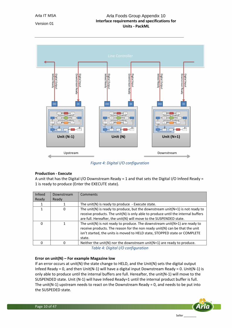
2.4 Digital I/O for synchronization of units This section describes the digital I/Os that is used for synchronization of units in a Line. The physical I/Os are used for fast control and synchronization of Units in the line:
Downstream ready: Digital input on unit (Ready =1, Not ready =0)
Infeed Ready : Digital output on unit (Ready =1, Not Ready =0)
Arla IT MSA Arla Foods Group Appendix 10 Interface requirements and specifications for
Units - PackML
Version 01
Page 10 of 47
Seller ________
Figure 4: Digital I/O configuration
Production - Execute A unit that has the Digital I/O Downstream Ready = 1 and that sets the Digital I/O Infeed Ready = 1 is ready to produce (Enter the EXECUTE state). Infeed Ready
Downstream Ready
Comments
1 1 The unit(N) is ready to produce - Execute state.
1 0 The unit(N) is ready to produce, but the downstream unit(N+1) is not ready to receive products. The unit(N) is only able to produce until the internal buffers are full. Hereafter, the unit(N) will move to the SUSPENDED state.
0 1 The unit(N) is not ready to produce. The downstream unit(N+1) are ready to receive products. The reason for the non ready unit(N) can be that the unit isn’t started, the units is moved to HELD state, STOPPED state or COMPLETE state.
0 0 Neither the unit(N) nor the downstream unit(N+1) are ready to produce.
Table 4: Digital I/O configuration Error on unit(N) – For example Magazine low If an error occurs at unit(N) the state change to HELD, and the Unit(N) sets the digital output Infeed Ready = 0, and then Unit(N-1) will have a digital input Downstream Ready = 0. Unit(N-1) is only able to produce until the internal buffers are full. Hereafter, the unit(N-1) will move to the SUSPENDED state. Unit (N-1) will have Infeed Ready=1 until the internal product buffer is full. The unit(N-1) upstream needs to react on the Downstream Ready = 0, and needs to be put into the SUSPEDED state.
Arla IT MSA Arla Foods Group Appendix 10 Interface requirements and specifications for
Units - PackML
Version 01
Page 11 of 47
Seller ________
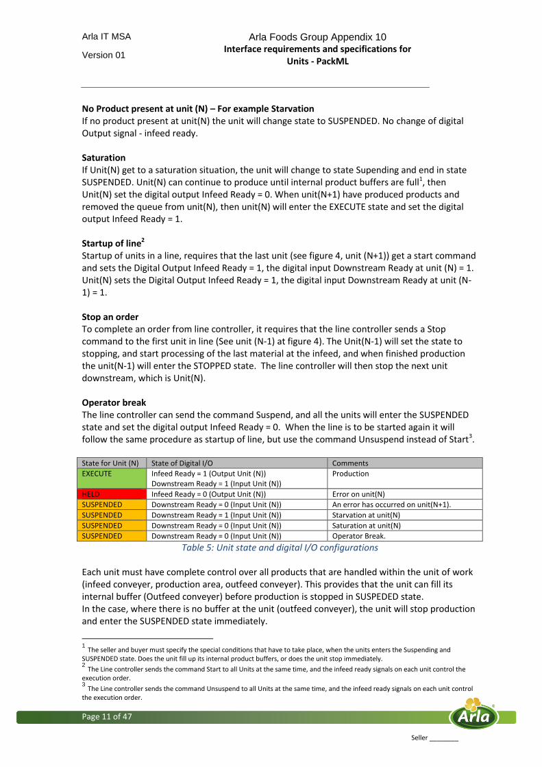
No Product present at unit (N) – For example Starvation If no product present at unit(N) the unit will change state to SUSPENDED. No change of digital Output signal - infeed ready. Saturation If Unit(N) get to a saturation situation, the unit will change to state Supending and end in state SUSPENDED. Unit(N) can continue to produce until internal product buffers are full1, then Unit(N) set the digital output Infeed Ready = 0. When unit(N+1) have produced products and removed the queue from unit(N), then unit(N) will enter the EXECUTE state and set the digital output Infeed Ready = 1. Startup of line2 Startup of units in a line, requires that the last unit (see figure 4, unit (N+1)) get a start command and sets the Digital Output Infeed Ready = 1, the digital input Downstream Ready at unit (N) = 1. Unit(N) sets the Digital Output Infeed Ready = 1, the digital input Downstream Ready at unit (N-1) = 1. Stop an order To complete an order from line controller, it requires that the line controller sends a Stop command to the first unit in line (See unit (N-1) at figure 4). The Unit(N-1) will set the state to stopping, and start processing of the last material at the infeed, and when finished production the unit(N-1) will enter the STOPPED state. The line controller will then stop the next unit downstream, which is Unit(N). Operator break The line controller can send the command Suspend, and all the units will enter the SUSPENDED state and set the digital output Infeed Ready = 0. When the line is to be started again it will follow the same procedure as startup of line, but use the command Unsuspend instead of Start3. State for Unit (N) State of Digital I/O Comments
EXECUTE Infeed Ready = 1 (Output Unit (N)) Downstream Ready = 1 (Input Unit (N))
Production
HELD Infeed Ready = 0 (Output Unit (N)) Error on unit(N)
SUSPENDED Downstream Ready = 0 (Input Unit (N)) An error has occurred on unit(N+1).
SUSPENDED Downstream Ready = 1 (Input Unit (N)) Starvation at unit(N)
SUSPENDED Downstream Ready = 0 (Input Unit (N)) Saturation at unit(N)
SUSPENDED Downstream Ready = 0 (Input Unit (N)) Operator Break.
Table 5: Unit state and digital I/O configurations Each unit must have complete control over all products that are handled within the unit of work (infeed conveyer, production area, outfeed conveyer). This provides that the unit can fill its internal buffer (Outfeed conveyer) before production is stopped in SUSPEDED state. In the case, where there is no buffer at the unit (outfeed conveyer), the unit will stop production and enter the SUSPENDED state immediately.
1 The seller and buyer must specify the special conditions that have to take place, when the units enters the Suspending and
SUSPENDED state. Does the unit fill up its internal product buffers, or does the unit stop immediately. 2 The Line controller sends the command Start to all Units at the same time, and the infeed ready signals on each unit control the
execution order. 3 The Line controller sends the command Unsuspend to all Units at the same time, and the infeed ready signals on each unit control
the execution order.
Arla IT MSA Arla Foods Group Appendix 10 Interface requirements and specifications for
Units - PackML
Version 01
Page 12 of 47
Seller ________
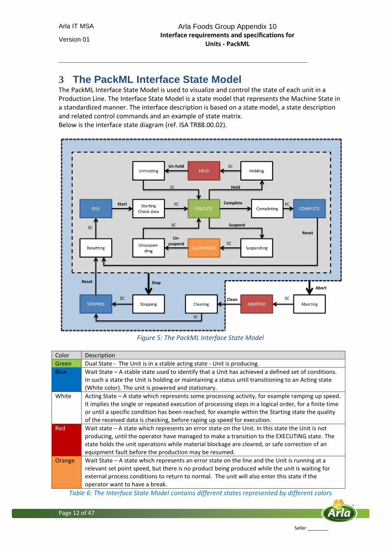
3 The PackML Interface State Model The PackML Interface State Model is used to visualize and control the state of each unit in a Production Line. The Interface State Model is a state model that represents the Machine State in a standardized manner. The interface description is based on a state model, a state description and related control commands and an example of state matrix. Below is the interface state diagram (ref. ISA TR88.00.02).
Figure 5: The PackML Interface State Model
Color Description
Green Dual State - The Unit is in a stable acting state - Unit is producing.
Blue Wait State – A stable state used to identify that a Unit has achieved a defined set of conditions. In such a state the Unit is holding or maintaining a status until transitioning to an Acting state (White color). The unit is powered and stationary.
White Acting State – A state which represents some processing activity, for example ramping up speed. It implies the single or repeated execution of processing steps in a logical order, for a finite time or until a specific condition has been reached, for example within the Starting state the quality of the received data is checking, before raping up speed for execution.
Red Wait state – A state which represents an error state on the Unit. In this state the Unit is not producing, until the operator have managed to make a transition to the EXECUTING state. The state holds the unit operations while material blockage are cleared, or safe correction of an equipment fault before the production may be resumed.
Orange Wait State – A state which represents an error state on the line and the Unit is running at a relevant set point speed, but there is no product being produced while the unit is waiting for external process conditions to return to normal. The unit will also enter this state if the operator want to have a break.
Table 6: The Interface State Model contains different states represented by different colors
Arla IT MSA Arla Foods Group Appendix 10 Interface requirements and specifications for
Units - PackML
Version 01
Page 13 of 47
Seller ________
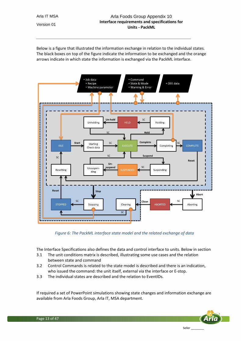
Below is a figure that illustrated the information exchange in relation to the individual states. The black boxes on top of the figure indicate the information to be exchanged and the orange arrows indicate in which state the information is exchanged via the PackML interface.
Figure 6: The PackML interface state model and the related exchange of data The Interface Specifications also defines the data and control interface to units. Below in section 3.1 The unit conditions matrix is described, illustrating some use cases and the relation
between state and command 3.2 Control Commands is related to the state model is described and there is an indication,
who issued the command: the unit itself, external via the interface or E-stop. 3.3 The individual states are described and the relation to EventIDs. If required a set of PowerPoint simulations showing state changes and information exchange are available from Arla Foods Group, Arla IT, MSA department.
Arla IT MSA Arla Foods Group Appendix 10 Interface requirements and specifications for
Units - PackML
Version 01
Page 14 of 47
Seller ________
The data interface covers the possibility to exchange related to the following issues:
OEE
Job data (Recipe data and unit parameters)
Warnings & errors
Additional information The seller is to have the main focus on the handling of the Interface State Model above, the local unit commands, that is to be handled by the Unit, and the external commands. It is important that the local and external commands are implemented in a way that ensures that the above Interface State Model always is followed. Download and upload of job data Download during startup: It is possible to download data to units in IDLE state. The downloaded data are validated within the unit during the logical processes in the starting state, before the units enters the EXECUTE state. Download to a stopped unit during production: A unit that is stopped locally has to upload the job data to the line controlling within the Stopping state. The operator may have changed the job data during production on the unit, and the jobs data used for production is to be send to the Line Controller in the unit state stopping. If production is resumed after a unit has been stopped, it is to be decided which job data is to be downloaded to the device. Is it the uploaded data from the unit or is it the original job data. It is recommended to give the option from the Line Controller4 to download the original or the uploaded job data to the single unit. Upload data from unit: The unit has to upload job data within the following states: Stopping, Completing and Clearing. OEE data The unit frequently sends the OEE data via the PackML interface. The OEE data is always send when there is state changes on the unit. Commands, states and modes Commands are send and force the unit to change state. State and mode information is send from the unit each time there is a state change on the unit.
4 To achieve this function, the appointed software engineer by buyer needs to create a unified system consisting of PLC
and IT system that can compare job data.

Arla IT MSA Arla Foods Group Appendix 10 Interface requirements and specifications for
Units - PackML
Version 01
Page 15 of 47
Seller ________
3.1 The Unit Conditions Matrix The table below shows Commands and in what interface State they can be received. For example the Current State is Execute and Magazine level is too low to produce. The Unit transit to HELD State and send a Warning & Error (Data Block: Warning & Error, see section 5.9) and Mode & State ( Data Block: Mode & State, see section 5.7) information.
Current state Operator Start production
Unit error: For example Magazine Low
Unit error corrected: For example Magazine Full
Downstream Not Ready
Downstream Ready
Issued by External via interface
Unit itself Unit itself Unit itself Unit itself
IDLE Start5
EXECUTE Hold Suspend
COMPLETE
STOPPED
SUSPENDED Un-suspend
HELD Un-Hold
ABORTED
Current state Operator want to
have a break.6 Operator want to restart unit after break
No product present - Starvation
Product present - No starvation
Order completed and the operator will stop production7
Issued by External via interface
External via interface
Unit itself Unit itself External via interface
IDLE Stop
EXECUTE Suspend Suspend Stop
COMPLETE Stop
STOPPED
SUSPENDED Suspend Un-suspend Un-suspend Stop
HELD Stop
ABORTED
Current state Product Counter
Reached Prepare for new order and reset unit externally
Operator will reset unit locally
Operator will stop unit Externally
Issued by Unit itself External via interface
Unit itself External via interface
IDLE Stop
EXECUTE Complete Stop
COMPLETE Reset Reset Stop
STOPPED Reset Reset
SUSPENDED Stop
HELD Stop
ABORTED
Table 7: The unit condition matrix
5 The operator has to activate each unit locally, which means that the unit is moved from STOPPED state to Resetting
state and then to IDLE state. Hereafter, the Line Controller can send the start command to start production. 6 It is not possible for the operator to put a unit in HELD state into suspended state when there is a break,
7 For the seller of the Line Controller, it is recommended to send a stop command to the first unit on the line, and
thereafter send a stop command to the next units downstream on the line. .

Arla IT MSA Arla Foods Group Appendix 10 Interface requirements and specifications for
Units - PackML
Version 01
Page 16 of 47
Seller ________
Current state Operator opens
safety door Operator press Local stop on Unit
Emergency Stop
Clear Faults
Issued by Unit itself Unit itself Unit itself Unit itself
IDLE Stop Abort
EXECUTE Hold Stop Abort
COMPLETE Stop Abort
STOPPED Abort
SUSPENDED Stop Abort
HELD Stop Abort
ABORTED Clear
Table 7: The unit condition matrix
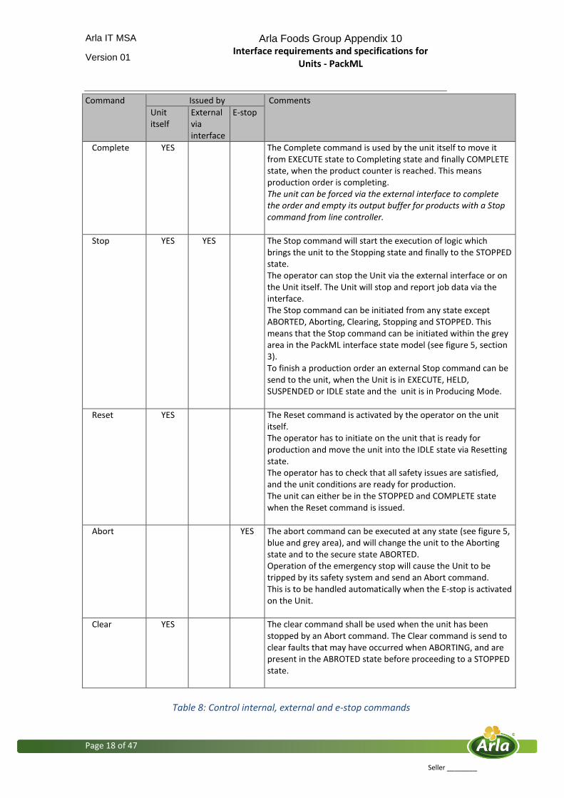
3.2 PackML Control Commands The Control Command provides the state command to drive a state change in the PackML Interface State Model. The processing of this command in the Unit Control System may be combined with remote or local Unit conditions to drive the interface state model from a Wait state to an Acting state. The unit shall always respond to a command. The Control Command can be set by the unit itself or remote via the PackML interface. It is described in the column, who is issuing the command. The Control Commands shall be exposed as an Integer, the specific command values are given in section 5.8 Data Block: Command.
Command Issued by Comments
Unit itself
External via interface
E-stop
Start YES (*)
YES The start command will move the unit into the Starting state. The start command will finally put the unit into the EXECUTE state or STOPPED state if an error occurs. The Line Controller is only allowed to give the Start command when the Unit is in Producing Mode and IDLE State. Start the Unit from Line Controller when the Recipe parameters are downloaded in IDLE state, will automatic start the unit, because the unit is already locally approved for production by operator (See reset command). (*) Start on the unit itself is only to be used when there is no Line Controller.
Hold YES The Hold command can only be executed automatically by the unit itself when an internal equipment fault is detected or by an operator command on the unit. The Hold command change the unit from the EXECUTE state to the Holding state. The Hold command offers the operator a safe way to intervene manually in the process, for example removing broken material from the in-feed. For example open a safe door. This means that all safe circuits for doors are activating the Hold command.
Table 8: Control internal, external and e-stop commands

Arla IT MSA Arla Foods Group Appendix 10 Interface requirements and specifications for
Units - PackML
Version 01
Page 17 of 47
Seller ________
Command Issued by Comments
Unit itself
External via interface
E-stop
Un-Hold YES The Unhold command releases the hold state and moves the unit to the Unholding state and then back to EXECUTE state. The Unhold command is a response to an Operator command to resume the production after an error on the unit. For example when operator has cleared material blockage or cleared a safe correction on the equipment. An Unhold command is always required and can never be initiated automatically by the unit itself.
Suspend YES YES The Suspend command from the unit itself is the result of starvation of material within the in-feeds or a result of saturation related out-feed blockage that prevents the Unit from Executing continued steady production. It is possible via the external interface to send the command Suspend, and the Unit will report that it is Suspending and the reason is break (EventID RPD – Removable Planned Down time). A unit that already is in SUSPENDED state and receives a external Suspend command, will only change the EventID from Line Failure (LF) to Break (RPD). The Suspend command have different meaning:
Suspend Command from line controller = Break
Suspend Command from unit itself = upstream or downstream problems
Unsuspend YES YES The Unsuspend command release the unit from SUSPENDED state and moves the unit to the Unsuspending state and finally to the EXECUTE state. The Unsuspend command change the unit from SUSPENDED state to Unsuspending state and EXECUTE state, when the Downstream Ready signal change to 1 and products present on infeed buffer the unit itself will give the Unsuspend command. When the operator wants to restart the production after a break. The Operator can then via the external interface send the command Unsuspend even if the unit already was SUSPENDED by the unit itself.
Table 8: Control internal, external and e-stop commands
Arla IT MSA Arla Foods Group Appendix 10 Interface requirements and specifications for
Units - PackML
Version 01
Page 18 of 47
Seller ________
Command Issued by Comments
Unit itself
External via interface
E-stop
Complete YES The Complete command is used by the unit itself to move it from EXECUTE state to Completing state and finally COMPLETE state, when the product counter is reached. This means production order is completing. The unit can be forced via the external interface to complete the order and empty its output buffer for products with a Stop command from line controller.
Stop YES YES The Stop command will start the execution of logic which brings the unit to the Stopping state and finally to the STOPPED state. The operator can stop the Unit via the external interface or on the Unit itself. The Unit will stop and report job data via the interface. The Stop command can be initiated from any state except ABORTED, Aborting, Clearing, Stopping and STOPPED. This means that the Stop command can be initiated within the grey area in the PackML interface state model (see figure 5, section 3). To finish a production order an external Stop command can be send to the unit, when the Unit is in EXECUTE, HELD, SUSPENDED or IDLE state and the unit is in Producing Mode.
Reset YES The Reset command is activated by the operator on the unit itself. The operator has to initiate on the unit that is ready for production and move the unit into the IDLE state via Resetting state. The operator has to check that all safety issues are satisfied, and the unit conditions are ready for production. The unit can either be in the STOPPED and COMPLETE state when the Reset command is issued.
Abort YES The abort command can be executed at any state (see figure 5, blue and grey area), and will change the unit to the Aborting state and to the secure state ABORTED. Operation of the emergency stop will cause the Unit to be tripped by its safety system and send an Abort command. This is to be handled automatically when the E-stop is activated on the Unit.
Clear YES The clear command shall be used when the unit has been stopped by an Abort command. The Clear command is send to clear faults that may have occurred when ABORTING, and are present in the ABROTED state before proceeding to a STOPPED state.
Table 8: Control internal, external and e-stop commands
Arla IT MSA Arla Foods Group Appendix 10 Interface requirements and specifications for
Units - PackML
Version 01
Page 19 of 47
Seller ________
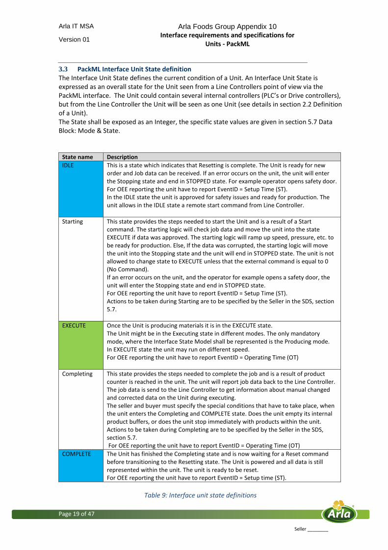
3.3 PackML Interface Unit State definition The Interface Unit State defines the current condition of a Unit. An Interface Unit State is expressed as an overall state for the Unit seen from a Line Controllers point of view via the PackML interface. The Unit could contain several internal controllers (PLC’s or Drive controllers), but from the Line Controller the Unit will be seen as one Unit (see details in section 2.2 Definition of a Unit). The State shall be exposed as an Integer, the specific state values are given in section 5.7 Data Block: Mode & State.
State name Description
IDLE This is a state which indicates that Resetting is complete. The Unit is ready for new order and Job data can be received. If an error occurs on the unit, the unit will enter the Stopping state and end in STOPPED state. For example operator opens safety door. For OEE reporting the unit have to report EventID = Setup Time (ST). In the IDLE state the unit is approved for safety issues and ready for production. The unit allows in the IDLE state a remote start command from Line Controller.
Starting This state provides the steps needed to start the Unit and is a result of a Start command. The starting logic will check job data and move the unit into the state EXECUTE if data was approved. The starting logic will ramp up speed, pressure, etc. to be ready for production. Else, If the data was corrupted, the starting logic will move the unit into the Stopping state and the unit will end in STOPPED state. The unit is not allowed to change state to EXECUTE unless that the external command is equal to 0 (No Command). If an error occurs on the unit, and the operator for example opens a safety door, the unit will enter the Stopping state and end in STOPPED state. For OEE reporting the unit have to report EventID = Setup Time (ST). Actions to be taken during Starting are to be specified by the Seller in the SDS, section 5.7.
EXECUTE Once the Unit is producing materials it is in the EXECUTE state. The Unit might be in the Executing state in different modes. The only mandatory mode, where the Interface State Model shall be represented is the Producing mode. In EXECUTE state the unit may run on different speed. For OEE reporting the unit have to report EventID = Operating Time (OT)
Completing This state provides the steps needed to complete the job and is a result of product counter is reached in the unit. The unit will report job data back to the Line Controller. The job data is send to the Line Controller to get information about manual changed and corrected data on the Unit during executing. The seller and buyer must specify the special conditions that have to take place, when the unit enters the Completing and COMPLETE state. Does the unit empty its internal product buffers, or does the unit stop immediately with products within the unit. Actions to be taken during Completing are to be specified by the Seller in the SDS, section 5.7. For OEE reporting the unit have to report EventID = Operating Time (OT)
COMPLETE The Unit has finished the Completing state and is now waiting for a Reset command before transitioning to the Resetting state. The Unit is powered and all data is still represented within the unit. The unit is ready to be reset. For OEE reporting the unit have to report EventID = Setup time (ST).
Table 9: Interface unit state definitions
Arla IT MSA Arla Foods Group Appendix 10 Interface requirements and specifications for
Units - PackML
Version 01
Page 20 of 47
Seller ________
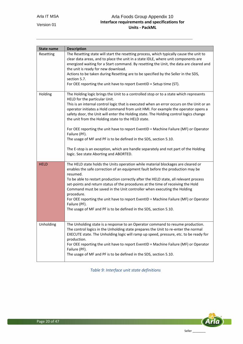
State name Description
Resetting The Resetting state will start the resetting process, which typically cause the unit to clear data areas, and to place the unit in a state IDLE, where unit components are energized waiting for a Start command. By resetting the Unit, the data are cleared and the unit is ready for new download. Actions to be taken during Resetting are to be specified by the Seller in the SDS, section 5.7. For OEE reporting the unit have to report EventID = Setup time (ST).
Holding The Holding logic brings the Unit to a controlled stop or to a state which represents HELD for the particular Unit. This is an internal control logic that is executed when an error occurs on the Unit or an operator initiates a Hold command from unit HMI. For example the operator opens a safety door, the Unit will enter the Holding state. The Holding control logics change the unit from the Holding state to the HELD state. For OEE reporting the unit have to report EventID = Machine Failure (MF) or Operator Failure (PF). The usage of MF and PF is to be defined in the SDS, section 5.10. The E-stop is an exception, which are handle separately and not part of the Holding logic. See state Aborting and ABORTED.
HELD The HELD state holds the Units operation while material blockages are cleared or enables the safe correction of an equipment fault before the production may be resumed. To be able to restart production correctly after the HELD state, all relevant process set-points and return status of the procedures at the time of receiving the Hold Command must be saved in the Unit controller when executing the Holding procedure. For OEE reporting the unit have to report EventID = Machine Failure (MF) or Operator Failure (PF). The usage of MF and PF is to be defined in the SDS, section 5.10.
Unholding The Unholding state is a response to an Operator command to resume production. The control logics in the Unholding state prepares the Unit to re-enter the normal EXECUTE state. The Unholding logic will ramp up speed, pressure, etc. to be ready for production. For OEE reporting the unit have to report EventID = Machine Failure (MF) or Operator Failure (PF). The usage of MF and PF is to be defined in the SDS, section 5.10.
Table 9: Interface unit state definitions

Arla IT MSA Arla Foods Group Appendix 10 Interface requirements and specifications for
Units - PackML
Version 01
Page 21 of 47
Seller ________
State name Description
Suspending This state suspending is required prior to the SUSPENDED wait state, and prepares the Unit to for example stops ironing, stops cutter, stops debagger, etc. The Unit may be running at a relevant set point speed, but there is no product being produced for the next unit downstream. The seller and buyer must specify the special conditions that have to take place, when the units enters the Suspending and SUSPENDED state. Does the unit fill up its internal product buffers, or does the unit stop immediately. The actions to be taken when the unit enters the Suspending state are to be defined in the SDS, section 5.7. Suspending is the result of starvation of material within the in-feeds or a result of saturation related out-feed blockage that prevents the Unit from Executing continued steady production. During the controlled sequence of Suspending the Unit will transition to a SUSPENDED state. The Suspending state might be forced by the operator via the external interface, when the operator wants to have a break. For OEE reporting the unit have to report EventID = Operating Time (OT), Line Failure (LF) or Removable Planned Down Time.
SUSPENDED The SUSPENDED state can be reached as a result of abnormal external process conditions. In the SUSPENDED state the Unit is waiting for external process conditions to return to normal and then transition to Unsuspending State and hence continue towards the normal EXECUTE state. If a safety door is opened in SUSPENDED state, the unit has to go immediately to HELD state via Unsuspending state, EXECUTE state and Holding state. For OEE reporting the unit have to report EventID = Line Failure (LF) when the Suspending control logics were initiated by the unit itself. The EventID = Removable Planned Down Time (For example a operator break) when the Suspending control logics are initiated via the external interface.
Unsuspending This state is a result of a Unit generated request from SUSPENDED state to go back to the EXECUTE state or an Unsuspend command via the external interface. This state is done prior to Execute state, and prepares the Unit for the Execute state. The actions of this state may include ramping up speeds, turning on vacuums, and the re-engagement of clutches. The unit is not allowed to change state to EXECUTE unless that the external command is equal to 0 (No Command). For OEE reporting the unit have to report EventID = Line Failure (LF) when the Suspending control logics were initiated by the unit itself. The EventID = Removable Planned Down Time (For example a operator break) when the Suspending control logics are initiated via the external interface. The actions to be taken when the unit enters the Unsuspending state are to be defined in the SDS, section 5.7.
Stopping This state executes the control logic which brings the Unit to a controlled stop as reflected by the STOPPED state. The unit will report job data back via the External interface. The job data are send to get information about eventual manual changes and corrects on the Unit itself during executing. The unit is not allowed to change state to STOPPED unless that the external command is equal to 0 (No Command). The seller and buyer must specify the special conditions that have to take place, when the units enters the Stopping and STOPPED state. Does the unit empty its internal product buffers, or does the unit stop immediately. The actions are to be defined in the SDS, section 5.7. For OEE reporting the unit have to report EventID = Operating Time (OT).
Table 9: Interface unit state definitions
Arla IT MSA Arla Foods Group Appendix 10 Interface requirements and specifications for
Units - PackML
Version 01
Page 22 of 47
Seller ________
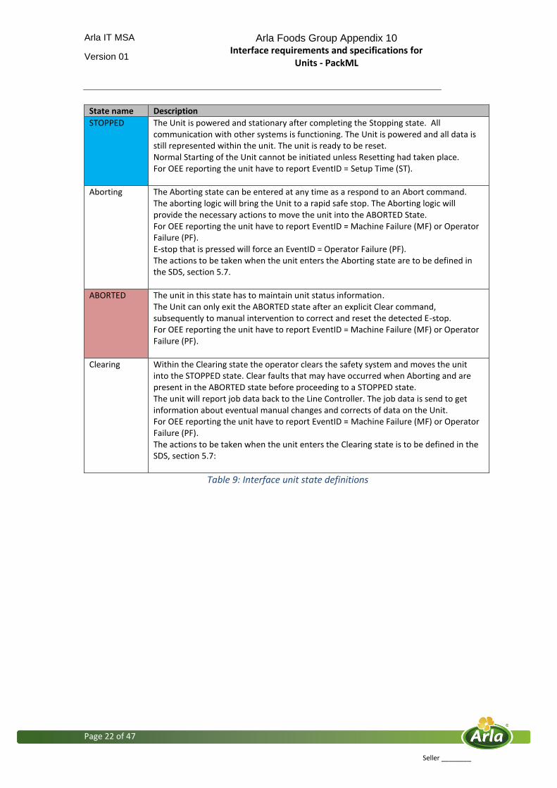
State name Description
STOPPED The Unit is powered and stationary after completing the Stopping state. All communication with other systems is functioning. The Unit is powered and all data is still represented within the unit. The unit is ready to be reset. Normal Starting of the Unit cannot be initiated unless Resetting had taken place. For OEE reporting the unit have to report EventID = Setup Time (ST).
Aborting The Aborting state can be entered at any time as a respond to an Abort command. The aborting logic will bring the Unit to a rapid safe stop. The Aborting logic will provide the necessary actions to move the unit into the ABORTED State. For OEE reporting the unit have to report EventID = Machine Failure (MF) or Operator Failure (PF). E-stop that is pressed will force an EventID = Operator Failure (PF). The actions to be taken when the unit enters the Aborting state are to be defined in the SDS, section 5.7.
ABORTED The unit in this state has to maintain unit status information. The Unit can only exit the ABORTED state after an explicit Clear command, subsequently to manual intervention to correct and reset the detected E-stop. For OEE reporting the unit have to report EventID = Machine Failure (MF) or Operator Failure (PF).
Clearing Within the Clearing state the operator clears the safety system and moves the unit into the STOPPED state. Clear faults that may have occurred when Aborting and are present in the ABORTED state before proceeding to a STOPPED state. The unit will report job data back to the Line Controller. The job data is send to get information about eventual manual changes and corrects of data on the Unit. For OEE reporting the unit have to report EventID = Machine Failure (MF) or Operator Failure (PF). The actions to be taken when the unit enters the Clearing state is to be defined in the SDS, section 5.7:
Table 9: Interface unit state definitions
Arla IT MSA Arla Foods Group Appendix 10 Interface requirements and specifications for
Units - PackML
Version 01
Page 23 of 47
Seller ________
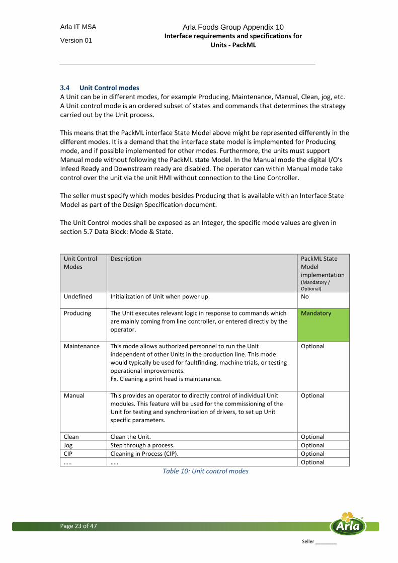
3.4 Unit Control modes A Unit can be in different modes, for example Producing, Maintenance, Manual, Clean, jog, etc. A Unit control mode is an ordered subset of states and commands that determines the strategy carried out by the Unit process. This means that the PackML interface State Model above might be represented differently in the different modes. It is a demand that the interface state model is implemented for Producing mode, and if possible implemented for other modes. Furthermore, the units must support Manual mode without following the PackML state Model. In the Manual mode the digital I/O’s Infeed Ready and Downstream ready are disabled. The operator can within Manual mode take control over the unit via the unit HMI without connection to the Line Controller. The seller must specify which modes besides Producing that is available with an Interface State Model as part of the Design Specification document. The Unit Control modes shall be exposed as an Integer, the specific mode values are given in section 5.7 Data Block: Mode & State.
Unit Control Modes
Description PackML State Model implementation (Mandatory / Optional)
Undefined Initialization of Unit when power up.
No
Producing The Unit executes relevant logic in response to commands which are mainly coming from line controller, or entered directly by the operator.
Mandatory
Maintenance This mode allows authorized personnel to run the Unit independent of other Units in the production line. This mode would typically be used for faultfinding, machine trials, or testing operational improvements. Fx. Cleaning a print head is maintenance.
Optional
Manual This provides an operator to directly control of individual Unit modules. This feature will be used for the commissioning of the Unit for testing and synchronization of drivers, to set up Unit specific parameters.
Optional
Clean Clean the Unit. Optional
Jog Step through a process. Optional
CIP Cleaning in Process (CIP). Optional
….. ….. Optional
Table 10: Unit control modes
Arla IT MSA Arla Foods Group Appendix 10 Interface requirements and specifications for
Units - PackML
Version 01
Page 24 of 47
Seller ________
3.5 Overall Equipment Effectiveness - OEE
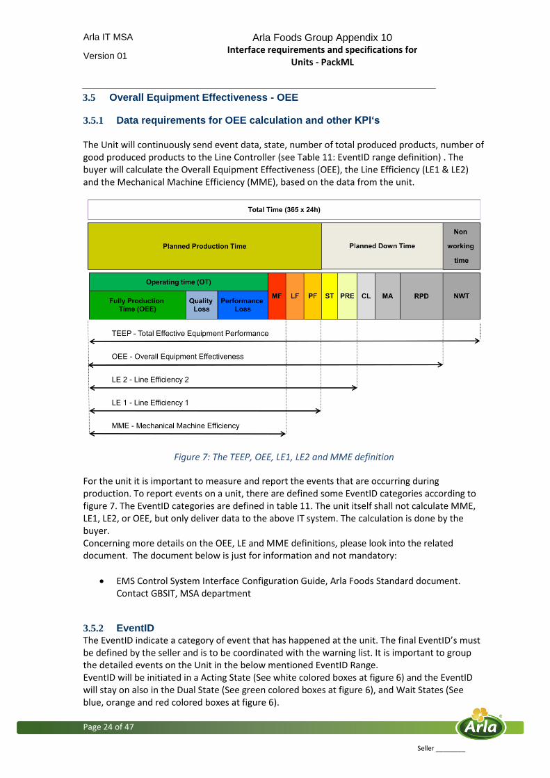
3.5.1 Data requirements for OEE calculation and other KPI‘s The Unit will continuously send event data, state, number of total produced products, number of good produced products to the Line Controller (see Table 11: EventID range definition) . The buyer will calculate the Overall Equipment Effectiveness (OEE), the Line Efficiency (LE1 & LE2) and the Mechanical Machine Efficiency (MME), based on the data from the unit.
Figure 7: The TEEP, OEE, LE1, LE2 and MME definition For the unit it is important to measure and report the events that are occurring during production. To report events on a unit, there are defined some EventID categories according to figure 7. The EventID categories are defined in table 11. The unit itself shall not calculate MME, LE1, LE2, or OEE, but only deliver data to the above IT system. The calculation is done by the buyer. Concerning more details on the OEE, LE and MME definitions, please look into the related document. The document below is just for information and not mandatory:
EMS Control System Interface Configuration Guide, Arla Foods Standard document. Contact GBSIT, MSA department
3.5.2 EventID
The EventID indicate a category of event that has happened at the unit. The final EventID’s must be defined by the seller and is to be coordinated with the warning list. It is important to group the detailed events on the Unit in the below mentioned EventID Range. EventID will be initiated in a Acting State (See white colored boxes at figure 6) and the EventID will stay on also in the Dual State (See green colored boxes at figure 6), and Wait States (See blue, orange and red colored boxes at figure 6).
Arla IT MSA Arla Foods Group Appendix 10 Interface requirements and specifications for
Units - PackML
Version 01
Page 25 of 47
Seller ________
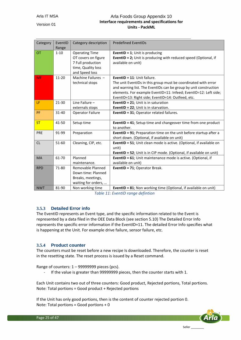
Category EventID Range
Category description Predefined EventIDs
OT 1-10 Operating Time OT covers on figure 7 Full production time, Quality loss and Speed loss
EventID = 1; Unit is producing EventID = 2; Unit is producing with reduced speed (Optional, if available on unit)
MF 11-20 Machine Failures – technical stops
EventID = 11: Unit failure. The unit EventIDs in this group must be coordinated with error and warning list. The EventIDs can be group by unit construction elements. For example EventID=11: Infeed; EventID=12: Left side; EventID=13: Right side; EventID=14: Outfeed, etc.
LF 21-30 Line Failure – externals stops
EventID = 21; Unit is in saturation EventID = 22; Unit is in starvation.
PF 31-40 Operator Failure EventID = 31; Operator related failures.
ST 41-50 Setup time EventID = 41; Setup time and changeover time from one product to another.
PRE 91-99 Preparation EventID = 91; Preparation time on the unit before startup after a short down. (Optional, if available on unit)
CL 51-60 Cleaning, CIP, etc. EventID = 51; Unit clean mode is active. (Optional, if available on unit) EventID = 52; Unit is in CIP mode. (Optional, if available on unit)
MA 61-70 Planned maintenance.
EventID = 61; Unit maintenance mode is active. (Optional, if available on unit)
RPD 71-80 Removable Planned Down time: Planned Breaks, meetings, waiting for orders, …
EventID = 71; Operator Break.
NWT 81-90 Non working time EventID = 81; Non working time (Optional, if available on unit)
Table 11: EventID range defintion
3.5.3 Detailed Error info
The EventID represents an Event type, and the specific information related to the Event is represented by a data filed in the OEE Data Block (see section 5.10) The Detailed Error Info represents the specific error information if the EventID=11. The detailed Error Info specifies what is happening at the Unit. For example drive failure, sensor failure, etc.
3.5.4 Product counter The counters must be reset before a new recipe Is downloaded. Therefore, the counter is reset in the resetting state. The reset process is issued by a Reset command. Range of counters: 1 – 99999999 pieces (pcs).
- If the value is greater than 99999999 pieces, then the counter starts with 1. Each Unit contains two out of three counters: Good product, Rejected portions, Total portions. Note: Total portions = Good product + Rejected portions If the Unit has only good portions, then is the content of counter rejected portion 0. Note: Total portions = Good portions + 0
Arla IT MSA Arla Foods Group Appendix 10 Interface requirements and specifications for
Units - PackML
Version 01
Page 26 of 47
Seller ________
3.5.5 Relation between PackML state, PackML mode and OEE EventID
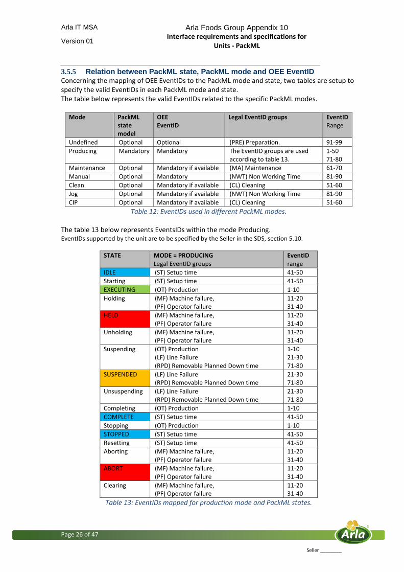
Concerning the mapping of OEE EventIDs to the PackML mode and state, two tables are setup to specify the valid EventIDs in each PackML mode and state. The table below represents the valid EventIDs related to the specific PackML modes.
Mode PackML state model
OEE EventID
Legal EventID groups EventID Range
Undefined Optional Optional (PRE) Preparation. 91-99
Producing Mandatory Mandatory The EventID groups are used according to table 13.
1-50 71-80
Maintenance Optional Mandatory if available (MA) Maintenance 61-70
Manual Optional Mandatory (NWT) Non Working Time 81-90
Clean Optional Mandatory if available (CL) Cleaning 51-60
Jog Optional Mandatory if available (NWT) Non Working Time 81-90
CIP Optional Mandatory if available (CL) Cleaning 51-60
Table 12: EventIDs used in different PackML modes. The table 13 below represents EventsIDs within the mode Producing. EventIDs supported by the unit are to be specified by the Seller in the SDS, section 5.10.
STATE MODE = PRODUCING Legal EventID groups
EventID range
IDLE (ST) Setup time 41-50
Starting (ST) Setup time 41-50
EXECUTING (OT) Production 1-10
Holding (MF) Machine failure, (PF) Operator failure
11-20 31-40
HELD (MF) Machine failure, (PF) Operator failure
11-20 31-40
Unholding (MF) Machine failure, (PF) Operator failure
11-20 31-40
Suspending (OT) Production (LF) Line Failure (RPD) Removable Planned Down time
1-10 21-30 71-80
SUSPENDED (LF) Line Failure (RPD) Removable Planned Down time
21-30 71-80
Unsuspending (LF) Line Failure (RPD) Removable Planned Down time
21-30 71-80
Completing (OT) Production 1-10
COMPLETE (ST) Setup time 41-50
Stopping (OT) Production 1-10
STOPPED (ST) Setup time 41-50
Resetting (ST) Setup time 41-50
Aborting (MF) Machine failure, (PF) Operator failure
11-20 31-40
ABORT (MF) Machine failure, (PF) Operator failure
11-20 31-40
Clearing (MF) Machine failure, (PF) Operator failure
11-20 31-40
Table 13: EventIDs mapped for production mode and PackML states.

Arla IT MSA Arla Foods Group Appendix 10 Interface requirements and specifications for
Units - PackML
Version 01
Page 27 of 47
Seller ________
3.6 Warning and Error information
The warning and Error interface represented by the data block Warning & Error is optional, but can be demand by the individual project.
3.6.1 Warning Warnings are used to give information to the above control system about a situation that will occur on the unit within a while. It is required if there is a demand for sending information to operators to do something on the unit to be able to produce without to stop. For example that a unit needs to get its cardboard magazine filled up within 15 minutes. The warnings are listed in an array of bits. See details in section 5.9 Data Block: Warning & Error.
3.6.2 Error
Errors are used to inform the above control system of all errors on the unit. That means it is possible to see the main error and the related errors. The main error is equal to the OEE detail error information. The errors will be logged and it is possible to show the errors in an alarm list. This can be used to get an centralized HMI for simple devices. The Errors are listed in an array of bits. See details in section 5.9 Data Block: Warning & Error.
3.7 Additional data
Additional data is used when special information is to be exchanged with the units. It is information that is not covered by the already defined job data, state, mode, commands, warning & Error and OEE. Unit to unit communication will be covered by additional data. It could be a palletizer asking a box filler to send one empty box to be able to finish a layer on a pallet.

Arla IT MSA Arla Foods Group Appendix 10 Interface requirements and specifications for
Units - PackML
Version 01
Page 28 of 47
Seller ________
4 Test requirements
To obtain this standardized interface a set of tests are required:
PackML Factory Acceptance Test – FAT
PackML Input & Out test – I/O test
PackML Site Acceptance Test – SAT (reference Is made to the General Terms)
PackML Take Over Certificate – TOC Test criteria’s and requirements must be a part of the Agreement (Reference is made to the list of Appendices). Such test criteria’s and requirements must be drafted by the seller and approved by the Buyer. Below is a short description of the contents of each test. PackML Factory Acceptance Test The purpose of this test is to test the interface data blocks and the I/O signals are working correctly and the physical Unit response to the exchanged information and commands. Reference is made to the Agreement. The test will take place at the seller and buyer provides a test case available that can act Line Controller and test the unit communication, state model, eventIDs and data structures. The test is carried out in order to verify that the data blocks can be exchanged between the Unit and the Line Controller. Furthermore, the content of the data blocks needs to be tested. It is warnings, errors, job data, and OEE data. The test will also include the control of the Unit from the Line Controller and the response from the Unit when an error occurs. For example open a door, send information about Held state and the OEE EventID. All relevant seller personnel must be present during the test. The Software engineer and the architect of the Unit must be present during the test. A software engineer appointed by the Buyer might be part of the test. PackML I/O test The I/O test will take place at the Place of Installation, and the purpose is to control that the wiring is done correctly between the Unit and the Line Controller. It might include control signals, Infeed ready, and downstream ready. The E-stop Is to be tested separately. The buyer appoints a software engineer that will describe the results in a test report. PackML Site Acceptance Testing The Site Acceptance Test is to verify that the Unit can run according to the defined performance criteria - Reference is made to the Agreement. It includes a full test of interface, the mapping and PackML states and OEE EventIDs, the exchange of warning and error information. The calculation of OEE figures will be tested. For the seller, the software engineer must be present during the test. The buyer must appoint a software engineer for PLC applications and a software engineer for MES applications for the test. The appoint software engineer for PLC applications must prepare a test report. Such test reports must be approved by the Buyer.
Arla IT MSA Arla Foods Group Appendix 10 Interface requirements and specifications for
Units - PackML
Version 01
Page 29 of 47
Seller ________
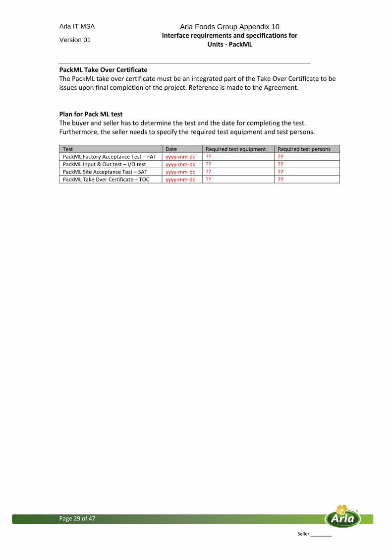
PackML Take Over Certificate The PackML take over certificate must be an integrated part of the Take Over Certificate to be issues upon final completion of the project. Reference is made to the Agreement. Plan for Pack ML test The buyer and seller has to determine the test and the date for completing the test. Furthermore, the seller needs to specify the required test equipment and test persons.
Test Date Required test equipment Required test persons
PackML Factory Acceptance Test – FAT yyyy-mm-dd ?? ??
PackML Input & Out test – I/O test yyyy-mm-dd ?? ??
PackML Site Acceptance Test – SAT yyyy-mm-dd ?? ??
PackML Take Over Certificate – TOC yyyy-mm-dd ?? ??
Arla IT MSA Arla Foods Group Appendix 10 Interface requirements and specifications for
Units - PackML
Version 01
Page 30 of 47
Seller ________
5 Software Design Specification requirements
The Software Design Specification (SDS) is part of the Purchase Agreement. A SDS template is available and it is mandatory to fill out. It is the seller that describes the SDS and the SDS must be approved by the Buyer. For each Unit a SDS document shall be created describing in details the actual data interfaces and connection types agreed with buyer. The structure and contents of the SDS is included in this section 5.1 to section 5.10. The seller has to specify and change the text marked with RED.
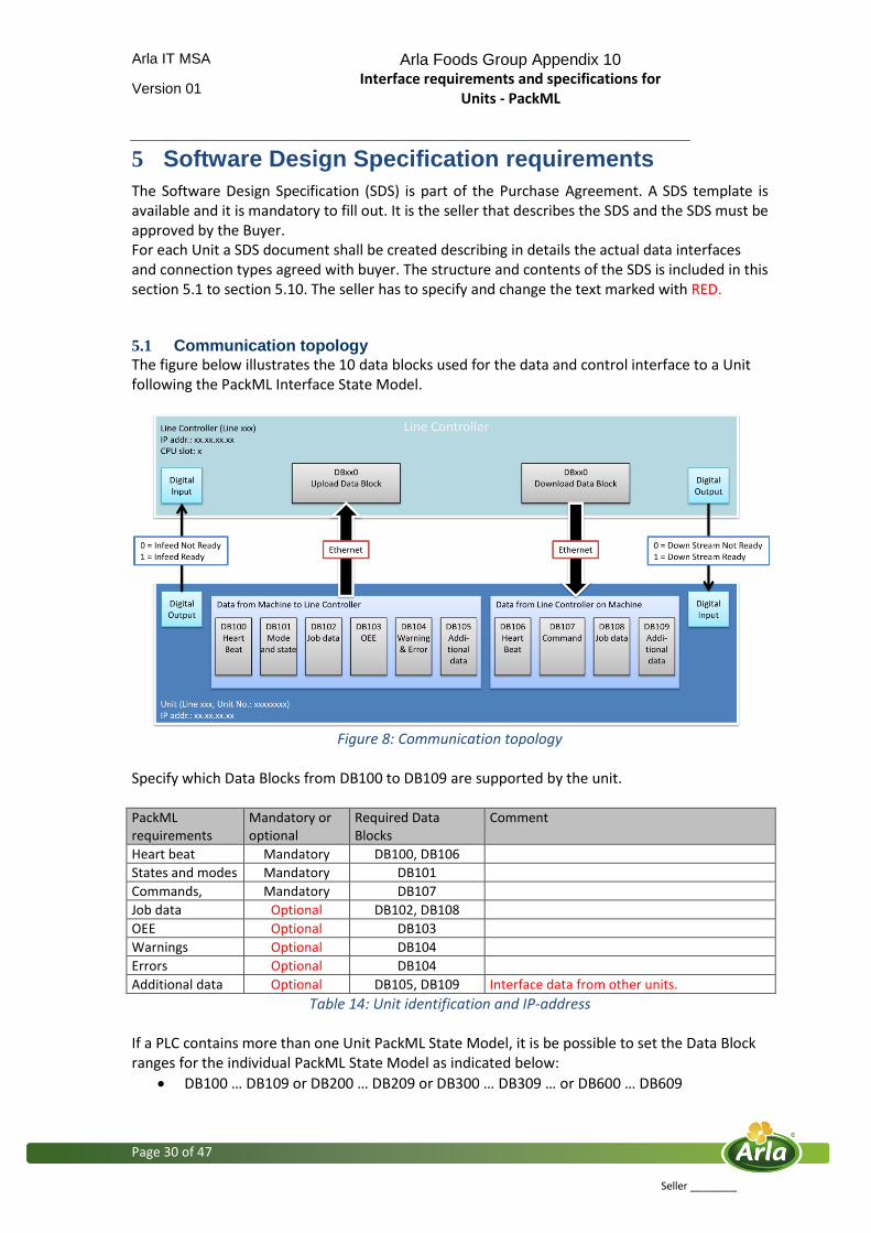
5.1 Communication topology The figure below illustrates the 10 data blocks used for the data and control interface to a Unit following the PackML Interface State Model.
Figure 8: Communication topology
Specify which Data Blocks from DB100 to DB109 are supported by the unit. PackML requirements
Mandatory or optional
Required Data Blocks
Comment
Heart beat Mandatory DB100, DB106
States and modes Mandatory DB101
Commands, Mandatory DB107
Job data Optional DB102, DB108
OEE Optional DB103
Warnings Optional DB104
Errors Optional DB104
Additional data Optional DB105, DB109 Interface data from other units.
Table 14: Unit identification and IP-address If a PLC contains more than one Unit PackML State Model, it is be possible to set the Data Block ranges for the individual PackML State Model as indicated below:
DB100 … DB109 or DB200 … DB209 or DB300 … DB309 … or DB600 … DB609

Arla IT MSA Arla Foods Group Appendix 10 Interface requirements and specifications for
Units - PackML
Version 01
Page 31 of 47
Seller ________
5.2 Ethernet communication
The Line Controller is an active part in the Ethernet communication. This means that the Line Controler handles the data transmission in both directions, to and from the data blocks in the Unit. The IP addresses is to be defined together with the buyer. Specify the identification of the unit and the related IP-address on site and during test.
Unit IP-address
Final adress On site 10.10.20.30
Test suitcase for FAT 10.0.0.1
Table 15: Unit identification and IP-address
5.2.1 Obtain the data block structure
There are several ways to implement the required interface. In the situation that the unit is on a non Siemens hardware and software, it is possible to introduce a gateway. The gateway could be a special communication card that is able to contain the data blocks 100 to 109 and is able to communicate via ProfiNet. Otherwise, the gateway could be a Siemens PLC (for example 315-2PN-DP). An illustration of the solution is given below on figure 9.
Figure 9: Communication topology

Arla IT MSA Arla Foods Group Appendix 10 Interface requirements and specifications for
Units - PackML
Version 01
Page 32 of 47
Seller ________
Specify how the PackML interface is implemented within the unit – Hardware configuration. Specification: ?????

Arla IT MSA Arla Foods Group Appendix 10 Interface requirements and specifications for
Units - PackML
Version 01
Page 33 of 47
Seller ________
Communication DB data definition
Basic definitions of data WORD/DWORD in the communication DB’s:
Figure 10: Definition of WORD/DWORD
Arla IT MSA Arla Foods Group Appendix 10 Interface requirements and specifications for
Units - PackML
Version 01
Page 34 of 47
Seller ________
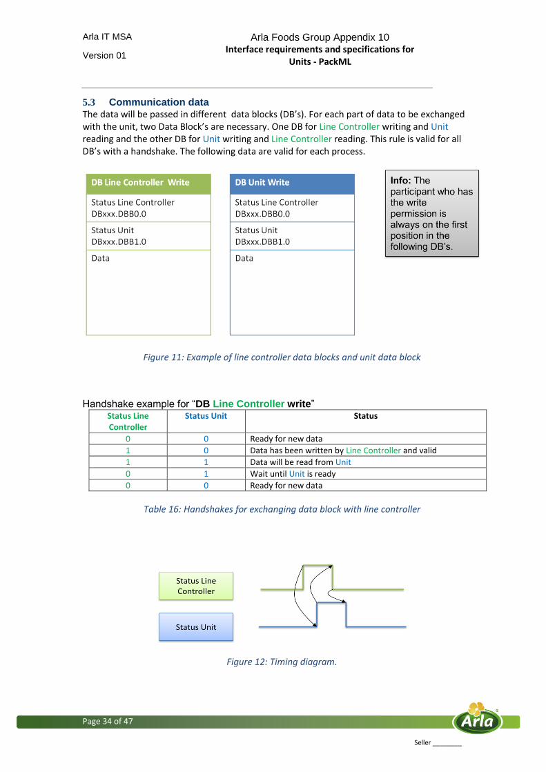
5.3 Communication data The data will be passed in different data blocks (DB’s). For each part of data to be exchanged with the unit, two Data Block’s are necessary. One DB for Line Controller writing and Unit reading and the other DB for Unit writing and Line Controller reading. This rule is valid for all DB’s with a handshake. The following data are valid for each process.
Figure 11: Example of line controller data blocks and unit data block
Handshake example for “DB Line Controller write”
Status Line Controller
Status Unit Status
0 0 Ready for new data
1 0 Data has been written by Line Controller and valid
1 1 Data will be read from Unit
0 1 Wait until Unit is ready
0 0 Ready for new data
Table 16: Handshakes for exchanging data block with line controller
Figure 12: Timing diagram.

Arla IT MSA Arla Foods Group Appendix 10 Interface requirements and specifications for
Units - PackML
Version 01
Page 35 of 47
Seller ________
5.4 Data Block: Heart Beat
DB100 Unit write
Addr. Description Data format Value range Unit Data length
0.0 Not used Byte 0-1 1 Byte
1.0 Not used Byte 0-1 1 Byte
2.0 Heart Beat Unit Increment frequency 2 Hz
INT 0-100 2 Bytes
Table 17: Data Block Heart Beat – Unit write
DB106 Line Controller write
Addr. Description Data format Value range Unit Data length
0.0 Not used Byte 0-1 1 Byte
1.0 Not used Byte 0-1 1 Byte
2.0 Heart Beat Line Controller Increment frequency 2 Hz
INT 0-100 2 Bytes
Table 18: Data Block Heart Beat – Line Controller write
The data block DB100 and DB106 are mandatory and the usage is defined. Range of counters heart beat: 0 – 100 If the value is greater than 100, then the counter starts with 0. The frequency for counting up is 2 Hz. If the heartbeats counter value does not change within 2 seconds, all other communications data must be considered invalid.

Arla IT MSA Arla Foods Group Appendix 10 Interface requirements and specifications for
Units - PackML
Version 01
Page 36 of 47
Seller ________
5.6 Data Block: Mode & State
DB101 Unit write
Addr. Description Data format Value range Unit Data length
0.0 Status Unit Byte 0-1 1 Byte
1.0 Status Line Controller Byte 0-1 1 Byte
2.0 Mode INT 1-32 2 Bytes
4.0 State INT 1-17 2 Bytes
Table 19: Data Block Mode & State – Unit write
The predefined modes are:
Modes Value Requirement Implemented on unit
Undefined 0 Optional ??
Producing 1 Mandatory YES
Maintenance 2 Optional ??
Manual 3 Optional ??
Reserved 4...15 Reserved No
Clean 16 Optional ??
Jog 17 Optional ??
CIP 18 Optional ??
User Defined 19 Optional ??
User Defined N Optional ??
Table 20: Predefined modes If additional modes are required, they must be specified by the seller. The seller must specify what modes are available in addition to “Producing”. The defined states are:
Table 21: Defined states and the related actions.
State Value Define the actions to be taken on unit
Clearing 1 ??
STOPPED 2 ?? Starting 3 ?? IDLE 4 ?? SUSPENDED 5 ?? EXECUTE 6 ?? Stopping 7 ?? Aborting 8 ?? ABORTED 9 ?? Holding 10 ?? HELD 11 ?? UnHolding 12 ?? Suspending 13 ?? Unsuspending 14 ?? Resetting 15 ?? Completing 16 ?? COMPLETE 17 ??
Arla IT MSA Arla Foods Group Appendix 10 Interface requirements and specifications for
Units - PackML
Version 01
Page 37 of 47
Seller ________
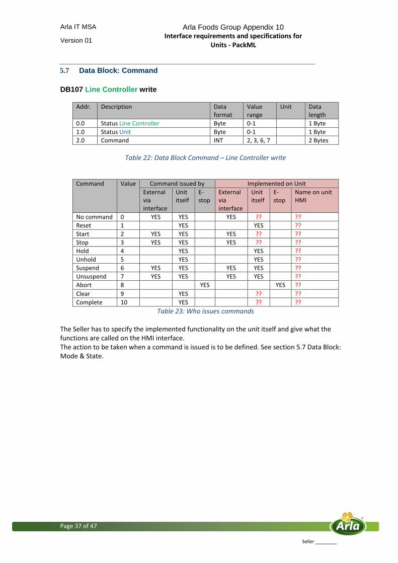
5.7 Data Block: Command
DB107 Line Controller write
Addr. Description Data format
Value range
Unit Data length
0.0 Status Line Controller Byte 0-1 1 Byte
1.0 Status Unit Byte 0-1 1 Byte
2.0 Command INT 2, 3, 6, 7 2 Bytes
Table 22: Data Block Command – Line Controller write
Command Value Command issued by Implemented on Unit
External via interface
Unit itself
E-stop
External via interface
Unit itself
E-stop
Name on unit HMI
No command 0 YES YES YES ?? ??
Reset 1 YES YES ??
Start 2 YES YES YES ?? ?? Stop 3 YES YES YES ?? ?? Hold 4 YES YES ?? Unhold 5 YES YES ?? Suspend 6 YES YES YES YES ?? Unsuspend 7 YES YES YES YES ?? Abort 8 YES YES ??
Clear 9 YES ?? ?? Complete 10 YES ?? ??
Table 23: Who issues commands
The Seller has to specify the implemented functionality on the unit itself and give what the functions are called on the HMI interface. The action to be taken when a command is issued is to be defined. See section 5.7 Data Block: Mode & State.

Arla IT MSA Arla Foods Group Appendix 10 Interface requirements and specifications for
Units - PackML
Version 01
Page 38 of 47
Seller ________
5.8 Data Block: Job data
Job data is defined as the recipe parameters that are required to run the Unit with a specified product. To determine the Job data it is recommend looking into which parameters the operator normally can configure manually on a similar Unit. The purpose is to get these data stored in the Arla Foods Group recipe handling system (RMS), and to monitor if operators during production change these parameters. The job data is to be defined for each individual Unit. The data blocks below can be described as a structure of data types. The exact data to put into the data structure is to be defined for each product number for the individual Unit. The data structure of the reserved data area in the Data Blocks can be changed. The data format in the structure can be Real, double integer, integer, and byte. DB102 Unit write
Addr. Description Data format
Value range
Unit Data length
0.0 Status Unit Byte 0-1 1 Byte
1.0 Status Line Controller Byte 0-1 1 Byte
2.0 Reserved for job data use 04.0 DINT ??? ??? 4 Bytes
6.0 Reserved for job data use 08.0 DINT ??? ??? 4 Bytes
10.0 Reserved for job data use 12.0 DINT ??? ??? 4 Bytes
14.0 Reserved for job data use 16.0 DINT ??? ??? 4 Bytes
18.0 Reserved for job data use 20.0 DINT ??? ??? 4 Bytes
22.0 Reserved for job data use 24.0 DINT ??? ??? 4 Bytes
26.0 Reserved for job data use 28.0 DINT ??? ??? 4 Bytes
30.0 Reserved for job data use 32.0 DINT ??? ??? 4 Bytes
34.0 Reserved for job data use 36.0 DINT ??? ??? 4 Bytes
38.0 Reserved for job data use 40.0 DINT ??? ??? 4 Bytes
42.0 Reserved for job data use 44.0 DINT ??? ??? 4 Bytes
46.0 Reserved for job data use 48.0 DINT ??? ??? 4 Bytes
50.0 Reserved for job data use 52.0 DINT ??? ??? 4 Bytes
54.0 Reserved for job data use 56.0 DINT ??? ??? 4 Bytes
58.0 Reserved for job data use 60.0 DINT ??? ??? 4 Bytes
62.0 Reserved for job data use 64.0 DINT ??? ??? 4 Bytes
66.0 Reserved for job data use 68.0 DINT ??? ??? 4 Bytes
70.0 Reserved for job data use 72.0 DINT ??? ??? 4 Bytes
74.0 Reserved for job data use 76.0 DINT ??? ??? 4 Bytes
78.0 Reserved for job data use 80.0 DINT ??? ??? 4 Bytes
82.0 Reserved for job data use 84.0 DINT ??? ??? 4 Bytes
Table 24: Data Block Job Data – Unit write
The “Job Data” is to be defined for the particular Unit together with Buyer. When the Unit reaches the states Stopping, Completing and Clearing, the Unit will automatically upload the job data to the Line Controller. By doing this it can be verified if an operator have changed a value direct on the Unit doing production.
Arla IT MSA Arla Foods Group Appendix 10 Interface requirements and specifications for
Units - PackML
Version 01
Page 39 of 47
Seller ________
DB108 Line Controller write
Addr. Description Data format
Value range
Unit Data length
0.0 Status Line Controller Byte 0-1 1 Byte
1.0 Status Unit Byte 0-1 1 Byte
2.0 Reserved for job data use 04.0 DINT ??? ??? 4 Bytes
6.0 Reserved for job data use 08.0 DINT ??? ??? 4 Bytes
10.0 Reserved for job data use 12.0 DINT ??? ??? 4 Bytes
14.0 Reserved for job data use 16.0 DINT ??? ??? 4 Bytes
18.0 Reserved for job data use 20.0 DINT ??? ??? 4 Bytes
22.0 Reserved for job data use 24.0 DINT ??? ??? 4 Bytes
26.0 Reserved for job data use 28.0 DINT ??? ??? 4 Bytes
30.0 Reserved for job data use 32.0 DINT ??? ??? 4 Bytes
34.0 Reserved for job data use 36.0 DINT ??? ??? 4 Bytes
38.0 Reserved for job data use 40.0 DINT ??? ??? 4 Bytes
42.0 Reserved for job data use 44.0 DINT ??? ??? 4 Bytes
46.0 Reserved for job data use 48.0 DINT ??? ??? 4 Bytes
50.0 Reserved for job data use 52.0 DINT ??? ??? 4 Bytes
54.0 Reserved for job data use 56.0 DINT ??? ??? 4 Bytes
58.0 Reserved for job data use 60.0 DINT ??? ??? 4 Bytes
62.0 Reserved for job data use 64.0 DINT ??? ??? 4 Bytes
66.0 Reserved for job data use 68.0 DINT ??? ??? 4 Bytes
70.0 Reserved for job data use 72.0 DINT ??? ??? 4 Bytes
74.0 Reserved for job data use 76.0 DINT ??? ??? 4 Bytes
78.0 Reserved for job data use 80.0 DINT ??? ??? 4 Bytes
82.0 Reserved for job data use 84.0 DINT ??? ??? 4 Bytes
Table 25: Data Block Job Data – Line Controller write
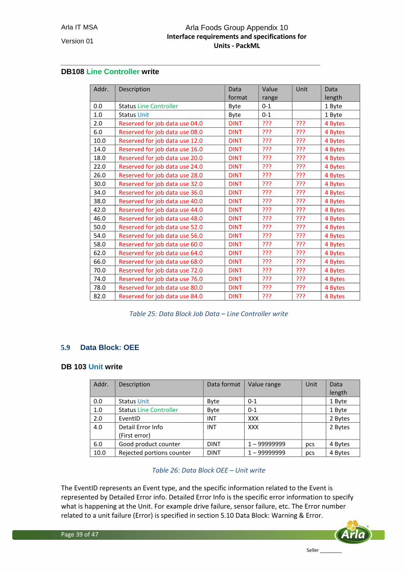
5.9 Data Block: OEE
DB 103 Unit write
Addr. Description Data format Value range Unit Data length
0.0 Status Unit Byte 0-1 1 Byte
1.0 Status Line Controller Byte 0-1 1 Byte
2.0 EventID INT XXX 2 Bytes
4.0 Detail Error Info (First error)
INT XXX 2 Bytes
6.0 Good product counter DINT 1 – 99999999 pcs 4 Bytes
10.0 Rejected portions counter DINT 1 – 99999999 pcs 4 Bytes
Table 26: Data Block OEE – Unit write
The EventID represents an Event type, and the specific information related to the Event is represented by Detailed Error info. Detailed Error Info is the specific error information to specify what is happening at the Unit. For example drive failure, sensor failure, etc. The Error number related to a unit failure (Error) is specified in section 5.10 Data Block: Warning & Error.

Arla IT MSA Arla Foods Group Appendix 10 Interface requirements and specifications for
Units - PackML
Version 01
Page 40 of 47
Seller ________
In table 27 the current EventIDs is to be defined for the particular unit in producing mode.
STATE MODE = PRODUCING Legal EventID groups
Specified EventID
IDLE (ST) Setup time ??
Starting (ST) Setup time ?? EXECUTING (OT) Production ?? Holding (MF) Machine failure,
(PF) Operator failure ??
HELD (MF) Machine failure, (PF) Operator failure
??
Unholding (MF) Machine failure, (PF) Operator failure
??
Suspending (OT) Production (LF) Line Failure (RPD) Removable Planned Down time
??
SUSPENDED (LF) Line Failure (RPD) Removable Planned Down time
??
Unsuspending (LF) Line Failure (RPD) Removable Planned Down time
??
Completing (OT) Production ?? COMPLETE (ST) Setup time ?? Stopping (OT) Production ?? STOPPED (ST) Setup time
(NWT) Non Working Time
??
Resetting (ST) Setup time ?? Aborting (MF) Machine failure,
(PF) Operator failure ??
ABORT (MF) Machine failure, (PF) Operator failure
??
Clearing (MF) Machine failure, (PF) Operator failure
??
Table 27: Specification of EventIDs for unit.
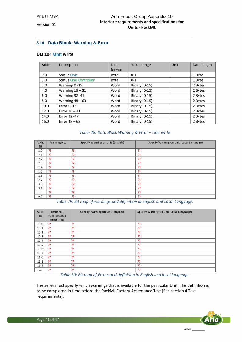
Arla IT MSA Arla Foods Group Appendix 10 Interface requirements and specifications for
Units - PackML
Version 01
Page 41 of 47
Seller ________
5.10 Data Block: Warning & Error
DB 104 Unit write
Addr. Description Data format
Value range Unit Data length
0.0 Status Unit Byte 0-1 1 Byte
1.0 Status Line Controller Byte 0-1 1 Byte
2.0 Warning 0 -15 Word Binary (0-15) 2 Bytes
4.0 Warning 16 – 31 Word Binary (0-15) 2 Bytes
6.0 Warning 32 -47 Word Binary (0-15) 2 Bytes
8.0 Warning 48 – 63 Word Binary (0-15) 2 Bytes
10.0 Error 0 -15 Word Binary (0-15) 2 Bytes
12.0 Error 16 – 31 Word Binary (0-15) 2 Bytes
14.0 Error 32 -47 Word Binary (0-15) 2 Bytes
16.0 Error 48 – 63 Word Binary (0-15) 2 Bytes
Table 28: Data Block Warning & Error – Unit write
Addr.
Bit Warning No. Specify Warning on unit (English) Specify Warning on unit (Local Language)
2.0 ?? ?? ??
2.1 ?? ?? ??
2.2 ?? ?? ??
2.3 ?? ?? ??
2.4 ?? ?? ??
2.5 ?? ?? ??
2.6 ?? ?? ??
2.7 ?? ?? ??
3.0 ?? ?? ??
3.1 ?? ?? ??
…. ?? ?? ??
9.7 ?? ?? ??
Table 29: Bit map of warnings and definition in English and Local Language.
Addr Bit
Error No. (OEE detailed
error info)
Specify Warning on unit (English) Specify Warning on unit (Local Language)
10.0 ?? ?? ??
10.1 ?? ?? ??
10.2 ?? ?? ??
10.3 ?? ?? ??
10.4 ?? ?? ??
10.5 ?? ?? ??
10.6 ?? ?? ??
10.7 ?? ?? ??
11.0 ?? ?? ??
11.1 ?? ?? ??
11.2 ?? ?? ??
…. ?? ?? ??
Table 30: Bit map of Errors and definition in English and local language. The seller must specify which warnings that is available for the particular Unit. The definition is to be completed in time before the PackML Factory Acceptance Test (See section 4 Test requirements).

Arla IT MSA Arla Foods Group Appendix 10 Interface requirements and specifications for
Units - PackML
Version 01
Page 42 of 47
Seller ________
The Detail Error Info is also part of the OEE Data Block, but for OEE DB it is only the first error that is send. By the Warning & Error Data Block all errors are send to the Line Controller for log purpose. The seller must specify all the different errors that can occur, and the seller must specify in table 30: error bit, error code, error text in English and Error text in local language according to the place of Installation. Specify the number of errors which should be available via the PackML interface: XXX If the number is more than 64 errors, do then extend the data block DB104 Warning & Error with necessary data length.
5.11 Data Block: Additional data
Additional data is to be used when the other Data Blocks not are sufficient. For example if special information is to be exchanged between two units via the Line Controller. The additional data is to be defined for each individual Unit. The data blocks below can be described as a structure of data types, and the data structure is to be defined for the particular purpose. DB105 Unit write
Addr. Description Data format
Value range
Unit Data length
0.0 Status Unit Byte 0-1 1 Byte
1.0 Status Line Controller Byte 0-1 1 Byte
2.0 Reserved for additional data use 04.0 DINT ??? ??? 4 Bytes
6.0 Reserved for additional data use 08.0 DINT ??? ??? 4 Bytes
10.0 Reserved for additional data use 12.0 DINT ??? ??? 4 Bytes
14.0 Reserved for additional data use 16.0 DINT ??? ??? 4 Bytes
18.0 Reserved for additional data use 20.0 DINT ??? ??? 4 Bytes
22.0 Reserved for additional data use 24.0 DINT ??? ??? 4 Bytes
26.0 Reserved for additional data use 28.0 DINT ??? ??? 4 Bytes
30.0 Reserved for additional data use 32.0 DINT ??? ??? 4 Bytes
34.0 Reserved for additional data use 36.0 DINT ??? ??? 4 Bytes
38.0 Reserved for additional data use 40.0 DINT ??? ??? 4 Bytes
42.0 Reserved for additional data use 44.0 DINT ??? ??? 4 Bytes
46.0 Reserved for additional data use 48.0 DINT ??? ??? 4 Bytes
50.0 Reserved for additional data use 52.0 DINT ??? ??? 4 Bytes
54.0 Reserved for additional data use 56.0 DINT ??? ??? 4 Bytes
58.0 Reserved for additional data use 60.0 DINT ??? ??? 4 Bytes
62.0 Reserved for additional data use 64.0 DINT ??? ??? 4 Bytes
66.0 Reserved for additional data use 68.0 DINT ??? ??? 4 Bytes
70.0 Reserved for additional data use 72.0 DINT ??? ??? 4 Bytes
74.0 Reserved for additional data use 76.0 DINT ??? ??? 4 Bytes
78.0 Reserved for additional data use 80.0 DINT ??? ??? 4 Bytes
82.0 Reserved for additional data use 84.0 DINT ??? ??? 4 Bytes
Table 31: Data Block Additional Data – Unit write
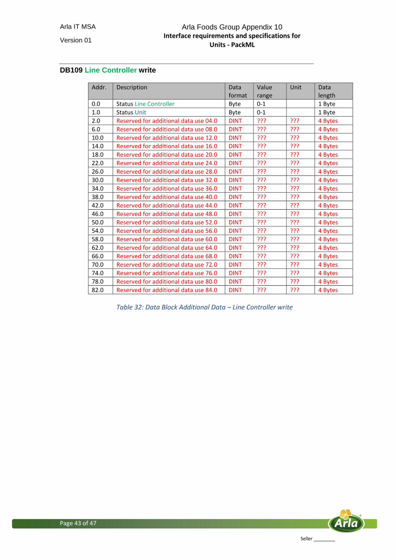
Arla IT MSA Arla Foods Group Appendix 10 Interface requirements and specifications for
Units - PackML
Version 01
Page 43 of 47
Seller ________
DB109 Line Controller write
Addr. Description Data format
Value range
Unit Data length
0.0 Status Line Controller Byte 0-1 1 Byte
1.0 Status Unit Byte 0-1 1 Byte
2.0 Reserved for additional data use 04.0 DINT ??? ??? 4 Bytes
6.0 Reserved for additional data use 08.0 DINT ??? ??? 4 Bytes
10.0 Reserved for additional data use 12.0 DINT ??? ??? 4 Bytes
14.0 Reserved for additional data use 16.0 DINT ??? ??? 4 Bytes
18.0 Reserved for additional data use 20.0 DINT ??? ??? 4 Bytes
22.0 Reserved for additional data use 24.0 DINT ??? ??? 4 Bytes
26.0 Reserved for additional data use 28.0 DINT ??? ??? 4 Bytes
30.0 Reserved for additional data use 32.0 DINT ??? ??? 4 Bytes
34.0 Reserved for additional data use 36.0 DINT ??? ??? 4 Bytes
38.0 Reserved for additional data use 40.0 DINT ??? ??? 4 Bytes
42.0 Reserved for additional data use 44.0 DINT ??? ??? 4 Bytes
46.0 Reserved for additional data use 48.0 DINT ??? ??? 4 Bytes
50.0 Reserved for additional data use 52.0 DINT ??? ??? 4 Bytes
54.0 Reserved for additional data use 56.0 DINT ??? ??? 4 Bytes
58.0 Reserved for additional data use 60.0 DINT ??? ??? 4 Bytes
62.0 Reserved for additional data use 64.0 DINT ??? ??? 4 Bytes
66.0 Reserved for additional data use 68.0 DINT ??? ??? 4 Bytes
70.0 Reserved for additional data use 72.0 DINT ??? ??? 4 Bytes
74.0 Reserved for additional data use 76.0 DINT ??? ??? 4 Bytes
78.0 Reserved for additional data use 80.0 DINT ??? ??? 4 Bytes
82.0 Reserved for additional data use 84.0 DINT ??? ??? 4 Bytes
Table 32: Data Block Additional Data – Line Controller write
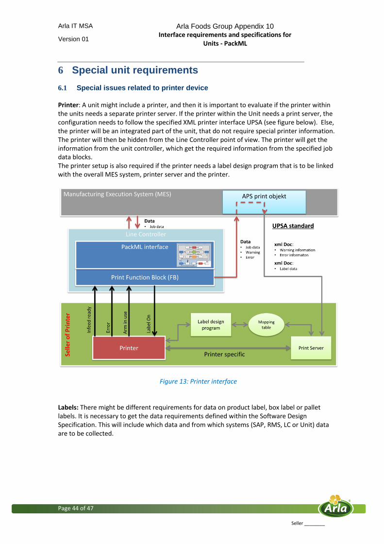
Arla IT MSA Arla Foods Group Appendix 10 Interface requirements and specifications for
Units - PackML
Version 01
Page 44 of 47
Seller ________
6 Special unit requirements
6.1 Special issues related to printer device Printer: A unit might include a printer, and then it is important to evaluate if the printer within the units needs a separate printer server. If the printer within the Unit needs a print server, the configuration needs to follow the specified XML printer interface UPSA (see figure below). Else, the printer will be an integrated part of the unit, that do not require special printer information. The printer will then be hidden from the Line Controller point of view. The printer will get the information from the unit controller, which get the required information from the specified job data blocks. The printer setup is also required if the printer needs a label design program that is to be linked with the overall MES system, printer server and the printer.
Figure 13: Printer interface Labels: There might be different requirements for data on product label, box label or pallet labels. It is necessary to get the data requirements defined within the Software Design Specification. This will include which data and from which systems (SAP, RMS, LC or Unit) data are to be collected.
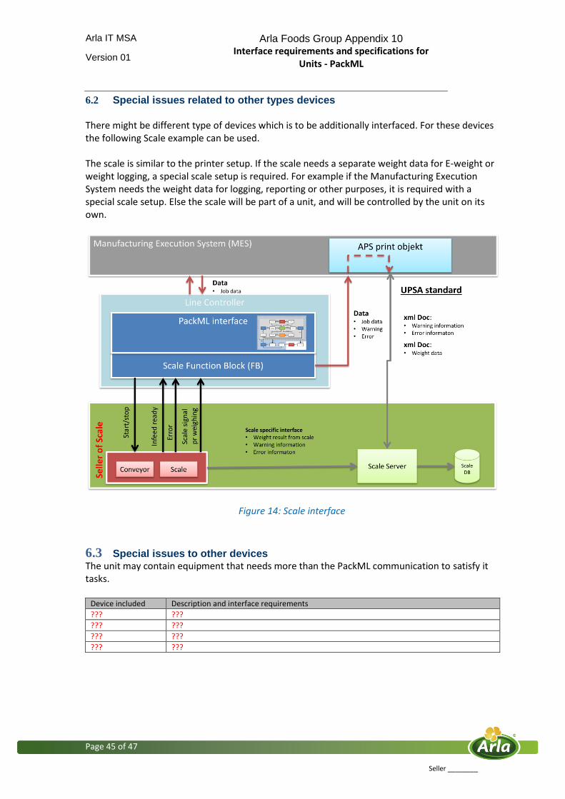
Arla IT MSA Arla Foods Group Appendix 10 Interface requirements and specifications for
Units - PackML
Version 01
Page 45 of 47
Seller ________
6.2 Special issues related to other types devices
There might be different type of devices which is to be additionally interfaced. For these devices the following Scale example can be used. The scale is similar to the printer setup. If the scale needs a separate weight data for E-weight or weight logging, a special scale setup is required. For example if the Manufacturing Execution System needs the weight data for logging, reporting or other purposes, it is required with a special scale setup. Else the scale will be part of a unit, and will be controlled by the unit on its own.
Figure 14: Scale interface
6.3 Special issues to other devices The unit may contain equipment that needs more than the PackML communication to satisfy it tasks.
Device included Description and interface requirements
??? ???
??? ???
??? ???
??? ???
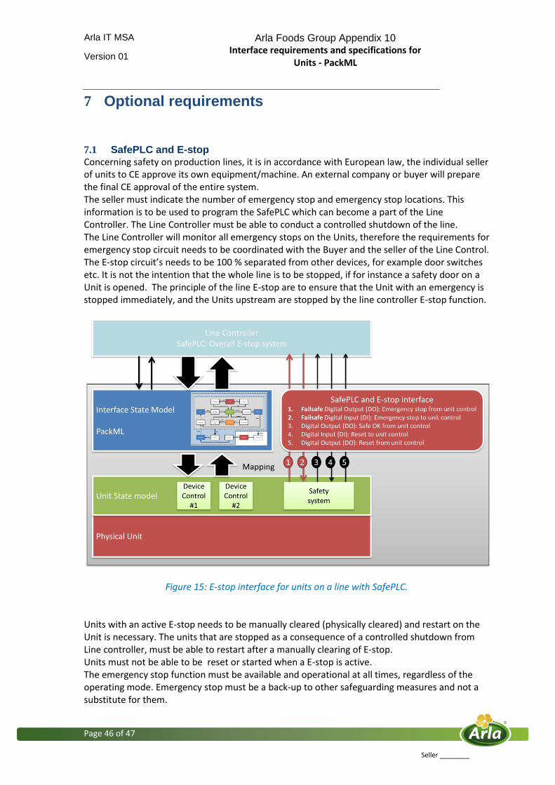
Arla IT MSA Arla Foods Group Appendix 10 Interface requirements and specifications for
Units - PackML
Version 01
Page 46 of 47
Seller ________
7 Optional requirements
7.1 SafePLC and E-stop
Concerning safety on production lines, it is in accordance with European law, the individual seller of units to CE approve its own equipment/machine. An external company or buyer will prepare the final CE approval of the entire system. The seller must indicate the number of emergency stop and emergency stop locations. This information is to be used to program the SafePLC which can become a part of the Line Controller. The Line Controller must be able to conduct a controlled shutdown of the line. The Line Controller will monitor all emergency stops on the Units, therefore the requirements for emergency stop circuit needs to be coordinated with the Buyer and the seller of the Line Control. The E-stop circuit’s needs to be 100 % separated from other devices, for example door switches etc. It is not the intention that the whole line is to be stopped, if for instance a safety door on a Unit is opened. The principle of the line E-stop are to ensure that the Unit with an emergency is stopped immediately, and the Units upstream are stopped by the line controller E-stop function.
Figure 15: E-stop interface for units on a line with SafePLC. Units with an active E-stop needs to be manually cleared (physically cleared) and restart on the Unit is necessary. The units that are stopped as a consequence of a controlled shutdown from Line controller, must be able to restart after a manually clearing of E-stop. Units must not be able to be reset or started when a E-stop is active. The emergency stop function must be available and operational at all times, regardless of the operating mode. Emergency stop must be a back-up to other safeguarding measures and not a substitute for them.
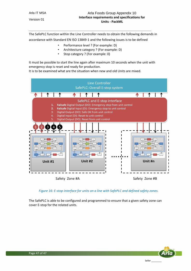
Arla IT MSA Arla Foods Group Appendix 10 Interface requirements and specifications for
Units - PackML
Version 01
Page 47 of 47
Seller ________
The SafePLC function within the Line Controller needs to obtain the following demands in
accordance with Standard EN ISO 13849-1 and the following issues is to be defined
• Performance level ? (For example: D) • Architecture category ? (For example: D) • Stop category ? (For example: 0)
It must be possible to start the line again after maximum 10 seconds when the unit with emergency stop is reset and ready for production. It is to be examined what are the situation when new and old Units are mixed.
Figure 16: E-stop interface for units on a line with SafePLC and defined safety zones.
The SafePLC is able to be configured and programmed to ensure that a given safety zone can cover E-stop for the related units.