apollo 9 mission operation report
TRANSCRIPT

8/8/2019 Apollo 9 Mission Operation Report
http://slidepdf.com/reader/full/apollo-9-mission-operation-report 1/230
M-932-69-09
MEMORANDUM
To: A/Acting Administrator
From: MA/ApoI lo Program Director
Subject: Apollo 9 Mission (AS-504)
.No earlier than 28 February 1969, we plan to launch the next Apollo/Saturn V mission,Apollo 9. This will be the second manned Saturn V flight, the third flight of a mannedApollo Command/Service Module, and the first flight of a manned Lunar Module.
The purpose of this mission is to demonstrate crew/space vehicle/mission support facilitiesperformance during a manned Saturn V mission with CSM ‘and LM, demonstrate LM/crewperformance, demonstrate performance of nominal and selected backup Lunar OrbitRendezvous mission activities, and assess CSM/LM consumables.
The launch will be the fourth Saturn V from Launch Complex 39A at Kennedy SpaceCenter. The launch window opens at 11:OO EST, closes at 14:00 EST and is determinedby lighting and ground station coverage requirements for rendezvous.
The nominal mission will include: ascent to orbit, CSM transposition and docking,CSM/LM separation from the S-IVB, five docked SPS burns, two unmanned S-IVBrestarts, LM systems evaluation, a docked DPS burn, EVA, LM active rendezvous,an unmanned APS burn to propellant depletion, CSM solo activities and three SPSburns, CM reentry, and recovery in the Atlantic.

8/8/2019 Apollo 9 Mission Operation Report
http://slidepdf.com/reader/full/apollo-9-mission-operation-report 2/230
Report No. M-932-69-09
MISSION OPERATION REPORT
The Prime Crew Members are(Left to right)

8/8/2019 Apollo 9 Mission Operation Report
http://slidepdf.com/reader/full/apollo-9-mission-operation-report 3/230
FOREWORD
MISSION OPERATION REPORTS are published expressly for the use of NASA SeniorManagement, as required by the Administrator in NASA Instruction 6-2-10, datedAugust 15, 1963. The purpose of these reports is to provide NASA Senior Manage-ment with timely, complete, and definitive information on flight mission plans, andto establish official mission objectives which provide the basis for assessment ofmission accomplishment .
Initial reports are prepared and issued for each flight project just prior to launch.Following launch, updating reports for each mission are issued to keep GeneralManagement currently informed of definitive mission results as provided in NASAInstruction 6-2-10.
Because of their sometimes highly technical orientation, distribution of these reportsis limited to personnel having program-project management responsibilities. TheOffice of Public Affairs publishes a comprehensive series of pre-launch and post-launch reports on NASA flight missions, which are available for general distribution.

8/8/2019 Apollo 9 Mission Operation Report
http://slidepdf.com/reader/full/apollo-9-mission-operation-report 4/230
M-932-69-09
CONTENTS
Page
General . . . . , . . . . . . . . . . . . . . . . . . . . . . . . . . . . . . 1
Program Development . . . . . . . . . . . . . . . . . . . . . . . . . . . . 1
The Apollo 9 Mission . . . . . . . . . . . . . . . . . . . . . . . . . . . .
NASA OMSF Primary Mission Objectives for Apollo 9 ...........Primary Objectives ...........................Detailed Test Objectives ........................
Launch Vehicle ..........................Spacecraft .............................
Secondary Objectives. .........................
Launch Vehicle ..........................Spacecraft .............................
Launch Countdown and Turnaround Capability AS-504 . . . . . , . . . . . 8Countdown . . . . . . . . . . . . . . . . . . . . . . . . . . . . . . . 8Scrub/Turnaround . . . . . . . . . . . . . . . . . . . . . . . . . . . . 8Turnaround Conditions vs. Time. . . . . . . . . . . . . . . . . . . . . 8
Post LV Cryogenic Load (with Fuel Cell Cryogenic Reservicing) . . 8Post LV Cryogenic Load (No Fuel Cell Cryogenic Reservicing) . . 10Pre LV Cryogenic Load (with Fuel Cell Cryogenic Reservicing) . . 10Pre LV Cryogenic Load (No Fuel Cell Cryogenic Reservicing) . . . 10

8/8/2019 Apollo 9 Mission Operation Report
http://slidepdf.com/reader/full/apollo-9-mission-operation-report 5/230
M-932-69-09
Page
Contingency Operations ........................ 24Aborts ............................... 27
Launch Aborts. ........................ 27
Earth Orbit Aborts ...................... 28
Rendezvous Aborts ...................... 28Al ternate Missions ......................... 28
Alternate Mission A. ..................... 28
Alternate Mission B...................... 28Alternate Mission C. ..................... 30Alternate Mission D. ................ ..... 30Alternate Mission E ................ ...... 30Alternate Mission F...................... 31Alternate Mission G ..................... 31
Space Vehicle Description ......................... 32
Launch Vehicle Description ...................... 32First Stage (S-IC) ................ ......... 32Second Stage (S-II) .................. ...... 34Third Stage (S-IVB) ................. ....... 34
Instrument Unit .......................... 34
Spacecraft Description ......................... 34Command Module ......................... 34
Service Module .......................... 36
Common Command and Service Module Systems .......... 36Guidance and Navigation System. .............. 36Stabilization and Control System ............... 36Reaction Control System 36

8/8/2019 Apollo 9 Mission Operation Report
http://slidepdf.com/reader/full/apollo-9-mission-operation-report 6/230
M-932-69-09
Page
.
.
Configuration Differences . . . . . . . . . . . . . . . . . . . .S-ICStage . . . . . . . . . . . . . . . . . . . . . . . . . ::::::
4141
S-II Stage . . . . . . . . . . . . . . . . . . . . . . . . . . . . . . .S-IVB Stage . . . . . . . . . . . . . . . . . . . . . . . . . . . .
41
Instrument Unit. . . . . . . . . . . . . . . . . . . . . . . . . . . : :
4142
Command Module. . . . . . . . . . . . . . . . . . . . . . . . . . . . 42
Lunar Module. . . . . . . . . . . . . . . . . . .Spacecraft LM Adapter. . . . . . . . . . . . . . : : : : : : : : : : :
4243
Human System Provisions . . . . . . . . . . . . . . . . , , . . . . . . . . 44
Launch Complex. . . . . . . . . . . . . . . . . . . . . . . . . . . . . . . 44
Mission Support........................ ....... 45
Recovery Support Plan. ........................General.
............................
Recovery Guidelines ................... : : : : : : :Recovery Areas .............................
Launch Site Landing Area .....................Launch Abort Landing Area ....................Primary Landing Area ........................................
: :econdary Landing Area.
Contingency Landing Area ....................Target Points. ...........................
Mobile Quarantine Facility (MQF) Simulation Opera tions. ......
4949495252525256
565757

8/8/2019 Apollo 9 Mission Operation Report
http://slidepdf.com/reader/full/apollo-9-mission-operation-report 7/230
M-932-69-09
Figure
1
2
3
4
5
6
7
a
9
10
11
12
LIST OF FIGURES
Title
Apollo 9 Mission Time and Event Correlation
Apollo 9 (AS-504) Mission Profile
Apollo 9 Summary Flight Plan
Apollo 9 Launch Day
Apollo 9 Second Day
Apollo 9 Third Day
Apollo 9 Fourth Day
Apollo 9 Fifth Day
Apollo 9 Sixth Thru Ninth Days
Apollo 9 Tenth Day
Apollo Saturn V Space Vehicle
Block II Command Module
Page
12
13
14
17
19
20
21
23
25
26
32
35

8/8/2019 Apollo 9 Mission Operation Report
http://slidepdf.com/reader/full/apollo-9-mission-operation-report 8/230
M-932-69-09
20
21
22
Mobile Quarantine Facility 58
Apollo 9 Prime Crew 60
Apollo 9 Backup Crew 61

8/8/2019 Apollo 9 Mission Operation Report
http://slidepdf.com/reader/full/apollo-9-mission-operation-report 9/230
M-932-69-09
LIST OF TABLES
Table Title
1 Launch Countdown Sequence ofEvents
2
3
7
Page
9
Apollo 9 Sequence of Events 15
Alternate Mission Sequence of Events -Apollo 9
29
Apollo 9 Weight Summary 33
MSFN Mobile Facilities 47
Network Configuration for the AS-504Mission
48
Recovery Forces, Apollo 9 51

8/8/2019 Apollo 9 Mission Operation Report
http://slidepdf.com/reader/full/apollo-9-mission-operation-report 10/230
M-932-69-09
APOLLO 9 MISSION OPERATION REPORT
The Apollo 9 Mission Operation Report is published in two volumes -I, The Mission Operation Report (MOR) and II, the Mission OperationReport Supplement.
This format was designed to provide a mission-oriented document in theMOR with only a very brief description of the space vehicle and supportfacilities. The MOR Suppl ement is a reference document with a morecomprehensive description of the space vehicle, launch complex, andmission monitoring, support, and control facilities.

8/8/2019 Apollo 9 Mission Operation Report
http://slidepdf.com/reader/full/apollo-9-mission-operation-report 11/230
M -932-69-09
GENERAL
The goal of the Apollo Program is to enhance the manned space flight capability of theUnited States by developing, through logical and orderly evolution, the ability to landmen on the moon and return them safely to earth.
To accomplish the goal of lunar landing and return in this decade, the Apollo Programhas focused on the development of a highly reliable launch vehicle and spacecraftsystem. This has been done through a logical sequence of Apollo missions designed toqualify the flight hardware , ground support systems, and operational personnel in the
most effective manner.
The Apollo 9 mission is the third manned flight of the Apollo Command and ServiceModule (CSM), the first manned flight of the Lunar Module (LM), and the secondmanned Saturn V mission. The mission is designed to test the space vehicle, missionsupport facilities, and crew with a complete Apollo spacecraft (CSM and LM) in earthorbit.
PROGRAM DEVELOPMENT
The first Saturn vehicle was successfully flown on 27 October 1961 to initiate operationsof the Saturn I Program.
A total of 10 Saturn I vehicles (SA-1 to SA-10) was successfully flight tested to pro-vide information on the integration of launch vehicle and spacecraft and to provideoperational experience with large multi-engined booster stages (S-l, S-IV).
The next generation of vehicles, developed under the Saturn IB Program, featured anuprated first stage (S-IB) an a more powerful new second stage (S-IVB). The firstSaturn IB was launched on 26 February 1966 The first three Saturn IB missions

8/8/2019 Apollo 9 Mission Operation Report
http://slidepdf.com/reader/full/apollo-9-mission-operation-report 12/230
M-932-69-09
The Apollo 4 mission was successfully executed on 9 November 1967. This mission
initiated the use of the Saturn V launch vehicle (SA-501) and required an orbitalrestart of the S-IVB third stage. The spacecraft for this mission consisted of an un-manned Command and Service Module (CSM) and a Lunar Module Test Article (LTA).The CSM Service Propulsion System (SPS) was exercised, including restart, and theCommand Module Block II heat shield was subjected to the combination of high heatload, high heat rate, and aerodynamic loads representative of lunar return entry.
The Apollo 5 mission was successfully launched and completed on 22 January 1968.
This was the fourth mission utilizing Saturn IB vehicles (SA-204). This flight providedfor unmanned orbital testing of the Lunar Module (LM-1). The LM structure, staging,and proper operation of the Lunar Module Ascent Propulsion System (APS) and DescentPropulsion System (DPS), including restart, were verified. Satisfactory performanceof the S-IVB/Instrument Unit (IU) in orbit was also demonstrated.
The Apollo 6 mission (second unmanned Saturn V) was successfully launched on 4 April1968. Some flight anomalies encountered included oscillation reflecting propulsion-structural longitudinal coupling, an imperfection in the Spacecraft LM Adapter (SLA)structural integrity, and certain malfunctions of the J-2 engines in the S-II and S-IVBstages. The spacecraft flew the planned trajectory, but pre-planned high velocityreentry conditions were not achieved. A majority of the mission objectives for Apollo 6were accomplished.
The Apollo 7 mission (first manned Apollo) was successfully launched on 11 October1968. This was the fifth and last planned Apollo mission utilizing Saturn IB launchvehicles (SA-205). Th e eleven-day mission provided the first orbital tests of theBlock II Command and Service Module. All Primary Mission Objectives were success-fully accomplished. In addition, all planned Detailed Test Objectives, plus threethat were not originally scheduled, were satisfactorily accomplished.

8/8/2019 Apollo 9 Mission Operation Report
http://slidepdf.com/reader/full/apollo-9-mission-operation-report 13/230
M-932-69-09
THE APOLLO 9 MISSION
Apollo 9 (AS-504) will be the fourth Saturn V Mission and the first manned flight ofthe Lunar Module (LM). M’ rssion duration is open-ended and currently planned forapproximately ten days (239 hours). This CSM/LM Operations Mission is designed toachieve an evaluation of a manned LM and to demonstrate the compatibility of theCSM and LM to perform combined operations typical of lunar missions.
The mission has been divided into six activity periods over the ten-day mission duration.
The first activity period will consist of launch and ascent to orbit, CSM transpositionand docking with the LM/IU/S-IVB, separation of the CSM/LM from the lU/S-IVB,two unmanned S-IVB engine restarts, and one docked-CSM/LM SPS burn. The secondactivity period will be taken up primarily by three more SPS burns. The third activityperiod will see the first LM operation including extensive LM systems checkout and thefirst docked-CSM/LM DPSb urn followed by the fifth SPS burn. The fourth activityperiod will be devoted to extravehicular activity (EVA) including a transfer from theLM to the CSM and return, and live TV of the CSM and LM by the EVA astronaut.
The fifth activity period will complete LM activities with two DPS burns, LM descentstage jettison, LM-active rendezvous including the first APS burn, and finally APSburn to propellant depletion. The sixth activity period will be devoted to CSM solooperations including three SPS burns, navigation exercises, a multispectral terrainphotography scientific experiment, CM reentry, and recovery.

8/8/2019 Apollo 9 Mission Operation Report
http://slidepdf.com/reader/full/apollo-9-mission-operation-report 14/230
M-932-69-09
NASA OMSF PRIMARY MISSION OBJECTIVES
FOR APOLLO 9
PRIMARY OBJECTIVES
. Demonstrate crew/space vehicle/mission support facilities performance duringa manned Saturn V mission with CSM and LM.
. Demonstrate LM/crew performance.
l Demonstrate performance of nominal and selected backup Lunar OrbitRendezvous (LOR) mission activities, including:
Transposition, docking, LM withdrawalIntervehicular crew transferExtravehicular capabilitySPS and DPS burns
LM active rendezvous and docking
. CSM/LM consumables assessment.
Lt. General, USAFApollo Program Director
C@orge E. Mueller
/Associate Administrator forManned Space Flight
Date: 14. FEB 69 Date: I7 /

8/8/2019 Apollo 9 Mission Operation Report
http://slidepdf.com/reader/full/apollo-9-mission-operation-report 15/230
M-932-69-09
DETAILED TEST OBJECTIVES
Mandatory and Principal Detailed Test Objectives (DTO’s) amplify and define moreexpl ic i tl y those basic tests, measurements, and evaluations that are planned to achievethe Primary Objectives of the Apollo 9 Mission.
Launch Vehicle
. Demonstrate S-lVB/IU attitude control capability during transposition, docking,and LM ejection (T, D, & E) maneuver.
Soacecraft
. Perform LM-ac tive rendezvous (20.27).
. Determine DPS duration effects and primary propulsion/vehicle interactions(13.12).
. Verify satisfactory performance of passive thermal subsystem (17. 17).
. Demonstrate LM structural integrity (17.18).
. Perform DPS burn including throttling, docked; and a short duration DPS burn,undoc ked ( 11.6).
. Perform long duration APS burns (13.11).
. Demonstrate Environmental Control System (ECS) performance during all LMactivities (14.0).

8/8/2019 Apollo 9 Mission Operation Report
http://slidepdf.com/reader/full/apollo-9-mission-operation-report 16/230
M-932-69-09
. Demonstrate RCS control of LM using manual and automatic PGNCS (11.7).
. Demonstrate S-band and VHF communication compatibility (20.22).
. Demonstrate RCS control of LM using manual and automatic AGS/CES (12.3).
. Demonstrate CSM attitude control, docked, during SPS burn (1.23).
. Demonstrate LA&active docking (20.28).
. Demonstrate LM ejection from SLA with CSM (20.25).
. Demonstrate CSM-active docking (20.24).
. Demonstrate LM-CSM undocking (20.26).
. Verify Inertial Measurement Unit (IMU) performance (11.10).
. Demonstrate Guidance, Navigation, and Control System (GNCS)/‘ManuaIThrust Vector Control (MTVC) takeover (2.9).
. Demonstrate LM rendezvous radar performance (16.4).
. Demonstrate LM/Manned Space Flight Network (MSFN) S-band communications
capability (20.21).
. Demonstrate IVT (20.34).
. Demonstrate AGS calibration and obtain performance data in flight (12.2).

8/8/2019 Apollo 9 Mission Operation Report
http://slidepdf.com/reader/full/apollo-9-mission-operation-report 17/230
M-932-69-09
. Perform landing radar self-test (16.6).
. Extravehicular Activity (20.35).
SECONDARY OBJECTIVES
Apollo secondary objectives are established by the development centers to provideadditional engineering or scientific data.
Launch Vehicle
. Verify S-IVB restart capability.
. Verify J-2 engine modifications.
. Confirm J-2 engine environment in S-II stage.
. Confirm launch vehicle longitudinal oscillation environment during S-IC
stage burn period.
. Demonstrate 02 Hz burner
. Demonstrate S-IVB propel
. Verify that modificationslongitudinal oscillations.
repressurization system operation.
ant dump and safing.
ncorporated in the S-IC stage suppress low-frequency
. Demonstrate 80-minute restart capability.
D d l i i bili

8/8/2019 Apollo 9 Mission Operation Report
http://slidepdf.com/reader/full/apollo-9-mission-operation-report 18/230
M-932-69-09
. Perform APS burn-to-depletion, unmanned (13.10).
. Obtain data on DPS plume effects on visibility (20.37).
. Perform CSM/LM electromagnetic compatibility test (20.120).
LAUNCH COUNTDOWN AND TURNAROUND CAPABILITY AS-504
COUNTDOWN
Countdown for the Apollo 9 mission will begin with a pre-count period starting atT-130.5 hours during which launch vehicle (LV) and spacecraf t preparations will takeplace independently. Coordinated space vehicle (SV) launch countdown activitiesbegin at T-28 hours. Table 1 shows the significant launch countdown events.
SCRUB/TURNAROUND
Scrub/turnaround times are based upon the amount of work required to return the space
vehicle to a safe condition and to complete the recycle activities necessary to resumelaunch countdown for a subsequent launch attempt. Planning guidelines for the variousscrub/turnaround plans are based upon no serial time for repairs or holds, or for systemsretesting resulting from repairs; performing tasks necessary to attain launch with the
same degree of confidence as for the first launch attempt; and, not requiring unloadingof hypergolic propellants and RP-1 from the SV.
TURNAROUND CONDITIONS VS. TIME +
Scrub can occur at any point in the countdown when weather, launch support facilitiesor SV conditions warrant. For a hold that results in a scrub prior to T-22 minutes,turnaround procedures are initiated from the point of hold Should a hold occur from

8/8/2019 Apollo 9 Mission Operation Report
http://slidepdf.com/reader/full/apollo-9-mission-operation-report 19/230
M-932-69-09
TABLE 1
LAUNCH COUNTDOWN SEQUENCE OF EVENTS
COUNTDOWNHRS: MIN: SEC
28: 00: 00 Start Countdown Clock21: 30: 00 R Start LM Stowage and Cabin Closeout24: 30: 00 R Start LM Systems Checks19: 30: 00 Start SV EDS Test13: 30: 00 Remove LM Platform12: 15: 00 SLA Closeout Complete11: 30: 00 R CSM Pre-ingress Operations09: 30: 00 CSM RF Voice Checks
09: 15: 00 R LV Closeout Complete09: 00: 00 Six-Hour Built-In Hold09: 00: 00 Clear Blast Danger Area08: 30: 00 Start MSS Move to Park Site08: 15: 00 Start LV Propellant Loading03: 38: 00 Start LV Propellant Replenishing02: 40: 00 Start Flight Crew Ingress02: 10: 00 Flight Crew Ingress Completed
01: 55: 00 Start MCC/CSM Command Checks01: 15: 00 Release Final Jimsphere00: 43: 00 Retract SA-9 to 12’ Park Position00: 42: 00 Arm LES
EVENT

8/8/2019 Apollo 9 Mission Operation Report
http://slidepdf.com/reader/full/apollo-9-mission-operation-report 20/230
M-932-69-09
time required for this turnaround results from flight crew egress; LV cryogenic unloading;LV ordnance operations and battery removal; LM supercritical helium (SHe) reservicing;CSM cryogenic reservicing; CSM battery removal and installation, and countdownresumption at T-28 hours.
Post-LV Cryogenic Load (No Fuel Cell Cryogenic Reservicing)
Turnaround time is 38 hours, 30 minutes, consisting of 29 hours, 30 minutes for recycletime and 9 hours for countdown time. Turnaround time is based upon: scrub occursbetween 16.2 seconds and 8.9 seconds during original countdown; the Range SafetyDestruct S&A units will remain connected; the CSM batteries do not require replacement;reservicing of the CSM or LM water systems not required; access to LM cabin not required.The time for this turnaround results from flight crew egress, LV cryogenic unloading, LMSHe reservicing, LV loading preparations, and countdown resumption at T-9 hours.
Pre-LV Cryogenic Load (with Fuel Cell Cryogenic Reservicing)
Turnaround time is 53 hours, 30 minutes, consisting of 44 hours, 30 minutes for recycletime and 9 hours for countdown time. Turnaround time is based upon: scrub occurs atT-8 hours of the original countdown; the Range Safety Destruct S&A units remain con-nected; the required S-II servoactuator inspection is waivered; reservicing of CSM orLM water systems not required; and access into LM cabin not required. The time re-quired for this turnaround results from CSM cryogenic reservicing, CSM battery removaland installation, LM SHe reservicing, and countdown resumption at T-9 hours.
Pre-LV Cryo Load (No Fuel Cell Cryo Reservicing)
The capability for a one-day turnaround exists at T-8 hours of the countdown. Thiscapability provides for a launch attempt at the opening of the next launch window

8/8/2019 Apollo 9 Mission Operation Report
http://slidepdf.com/reader/full/apollo-9-mission-operation-report 21/230
M-932-69-09
DETAILED FLIGHT MISSION DESCRIPTION
NOMINAL MISSION
The Apollo 9 Mission Plan is divided into six activity periods which span eleven workdays over eleven calendar days. The relationships among these periods and days, andthe major scheduled activities are shown to scale in Figure 1. Each work day willterminate with completion of a crew sleep period.
A summary profile of the Apollo 9 mission is shown in Figure 2 and a detailed summaryof the Apollo 9 Flight Plan is given in Figure 3.
The sequence of events for the Apollo 9 mission is given in Table 2. Launch vehicle(LV) time base (TB) notations are also included. Time bases may be defined as preciseinitial points upon which succeeding critical preprogrammed activities or functions maybe based. The TB’s noted in Table 2 are for a nominal mission and presuppose nominalLV performance. However, should the launch vehicle stages produce non-nominalperformance, the launch vehicle computer will recompute the subsequent TB’s andassociated burns to correct LV performance to mission rules.
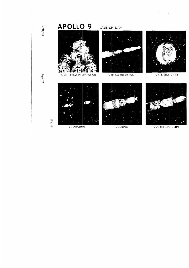
First Period of Activity (Figure 4)
The Apollo 9 mission will be launched from Kennedy Space Center, Launch Complex 39,Pad A, on a flight azimuth of 72’. The launch window opens at 1100 EST, closes at1400 EST, and is determined by lighting and ground station coverage requirements forCSM/LM rendezvous.
The Apollo 9 mission will begin with full S-IC and S-II launch vehicle stage burns andpartial burn of the S-IVB stage to insert the S-IVB, Instrument Unit (IU), Lunar Module

8/8/2019 Apollo 9 Mission Operation Report
http://slidepdf.com/reader/full/apollo-9-mission-operation-report 22/230
APOLLO9 MISSIONTIME AND EVENT ORRELATIONFIRST SECOND THIRD FOURTH FIFTH SIXTH SEVENTH EIGHTH NINTH TENTH
CALENDARELEVENTH
DAY LAUNCH
.CSM SOLO ACTIVITIES
.APS BURN.6TH SPS BURN
SPS BURN l 5TH DOCKEDSPS BURN
TO DEPLE-TION
.7TH SPS BURN
0 ~TH sps BURN (DEORBIT)
. SPLASHDOWN

8/8/2019 Apollo 9 Mission Operation Report
http://slidepdf.com/reader/full/apollo-9-mission-operation-report 23/230
TFIRST PERIOD OF ACTIVITIES
@ LNNai@ INSERlICW INTO
ID3N. MI. CIRORBIT
@ TANDD-LMEJECTION
@ 2NIJ S-M nuRN
@ 1Sl SPS BURN
@ MD s-IVE Bum
FOURTH PERIOD OF ACTIVKIES
EVAl PEPlOO DURAlloN ABOUT 11 HCwS lcET 6B.10 TO 7lt:Y)l
INCLUDING:
DON l DOfF LCC AND PGA’S (I HR. EA. I- 2 HRS
TUHKL HARDWAR AND IV1 OPNS - 2 112HRS
EVA - 2HRS
NA PREPARATIONS AND POST EVA - 3 HRS
EAT - IHR
0 EVA DlJRAlloN ABOUT 2 HRS.. IOMIN IGET 73:kl TO IS:201INa!JDEs:
EGRSS. EVTTO CM. AND INGRESS CM - 2DMIN.
11-a RETRIEVE MERMAL SAMPLES AND RST - I5 MIN.co EGESS CM. EVT TOLM. AND LTRIEVE.
SAMPLES - ISMIN.IQ EVALUATE NIGHT LIGHTING * 35MIN.
PHOTOGRAPHY. TV AND INGRSS LM - 45MIN.
APOLLO9 (AS-504) MSSION PROFILE
SECOND PERIOD OF ACTIVKIES
@ d(D SPS BUW
@ 3RD SPS BURN
@ 4TH SPS BURN
FIFTH PERIOD OF ACTIVITIES
l PERIODTERMINATED YAPS BURNTODEPLETION
THIRD PERKID OF ACTMTIES
3 LM SYSlEMSEVALUATlOll
3 DCCRD DPS BUffl
3 5lH SPS numd
SIXTH PERlOD OF ACTlVlTlES
@ 6TH SPS Bum &4lmDow
@ 7TH SPS BURN l WEST AllANTIC

8/8/2019 Apollo 9 Mission Operation Report
http://slidepdf.com/reader/full/apollo-9-mission-operation-report 24/230
a
0
APOLLO 9 SUMMARY FLIGHT PLAN

8/8/2019 Apollo 9 Mission Operation Report
http://slidepdf.com/reader/full/apollo-9-mission-operation-report 25/230
M-932-69-09
*Ground Elapsed Time (GET)HR: MIN: SEC
00: 00: 0000: 00: 00.39100: 01: 2100: 02: 1400: 02: 4000: 02: 4000: 02: 4200: 03: 10
00: 03: 1600: 08: 5100: 08: 5200: 08: 5500: 10: 4900: 10: 5902: 33: 4902: 43: 00
03: 05: 0004: 08: 5704: 36: 1204 45 50
TABLE 2
APOLLO 9
SEQUENCE OF EVENTS
Event
First MotionTimebase 1Maximum Dynamic PressureS-K Center Engine Cutoff - TB2S-K Outboard Engine Cutoff - TB3S-lC/S-I I Separa tionS-II IgnitionJettison S-II Aft Interstage
Jettison Launch Escape TowerS-II Engine Cu toff Command - TB4S-II/S-IVB SeparationS-IVB Engine Ignition
S-IVB Engine Cutoff - TB5Parking Orbit InsertionSepara tion and Docking Maneuver InitiationSpacecraft Separation
Spacecraft Docking (Approximately)Spacecraft Final SeparationS-IV6 Restart Preps. - TB6S IVB R i iti (2 d b )

8/8/2019 Apollo 9 Mission Operation Report
http://slidepdf.com/reader/full/apollo-9-mission-operation-report 26/230
M-932-69-09
06: 24: 0406: 42: 1922: 12: 0025: 18: 3028: 28: 0046: 27: 0049: 42: 0054: 25: 1975: 00: 00
92: 39: 0093: 07: 4093: 51: 3495: 43: 2296: 21: 0097: 05: 2798: 00: 1099: 13: 00
101: 58: 00121: 58: 48169: 47: 54238: 45: 00238: 59: 47239: 10: 38239: 16: --
Start LH2 DumpLH2 Dump CutoffSPS Burn 2SPS Burn 3SPS Burn 4TV Transmission, LM InteriorDocked DPS BurnSPS Burn 5TV Transmission, CSM/lM Exterior by EVA LMP
UndockingCSM/LM SeparationDPS PhasingDPS InsertionConcentric Sequence Initiation - RCS BurnConstant Delta Height - APS BurnTerminal Phase InitiationCSM/LM Docking (Approximately)
APS Burn to Propellant DepletionSPS Burn 6SPS Burn 7SPS Burn 8 (Deorbit)Entry Interface (400,000 feet)Drogue Chute Deployment (25,000 feet Approximately)Splashdown (Approximately)
8/8/2019 Apollo 9 Mission Operation Report
http://slidepdf.com/reader/full/apollo-9-mission-operation-report 27/230
00a2
86
P
1

8/8/2019 Apollo 9 Mission Operation Report
http://slidepdf.com/reader/full/apollo-9-mission-operation-report 28/230
M-932-69-09
Propulsion System (SPS) b urn will be performed to raise apogee of the CSM/LM orbitto 128 nautical miles. The S-IVB and SPS burns will be spaced to take advantage of
the MSFN ground coverage before the end of the first activity period. A little aftersix hours GET, the S-IVB will be ignited a third time producing a sufficient increasein velocity to go into solar orbit.
Second Period of Activity (Figure 5)
The second period of activity will be comprised of three docked-CSM/LM SPS burns.The first two burns in this period will be long duration, out-of-plane, and will adjust
perigee to 115 nautical miles and apogee to 271 nautical miles. These burns willsatisfy the CSM docked Digital Auto Pilot (DAP) stability margin test obiective. Theseburns will also reduce the CSM weight to a level consistent with the SM RCS propellantrequirements to deorbit or to effect a LM rescue if required during the fifth period LM-active rendezvous. The burns will also provide nodal shift to assure proper lighting andrendezvous tracking. The third SPS burn in this period will be used to adjust phasingconditions for the LM-active rendezvous but will not change orbital parameters.
Third Perrod of Activity (Figure 6)
This period will be devoted primarily to checkout and performance evaluation of theLM systems including a docked Descent Propulsion System (DPS) engine burn of sufficientduration to evaluate performance of the LM Primary Guidance, Navigation, and ControlSystem (PGNCS) digital autopilot and manual throttling of the DPS engine. Activitieswill begin with the intervehicular transfer (IVT) of the Commander (CDR), the LunarModule Pilot (LMP), and equipment from the CSM to the LM. The LM systems will then
be activated and checked out for the first time in the mission, commencing the systemsperformance evaluation. Following the docked DPS burn, the LM will be powered downand the CDR and LMP will return from the LM to the CSM via the IVT tunnel. A docked
b ll h l h b l l d h d

8/8/2019 Apollo 9 Mission Operation Report
http://slidepdf.com/reader/full/apollo-9-mission-operation-report 29/230
2
86
P
1

8/8/2019 Apollo 9 Mission Operation Report
http://slidepdf.com/reader/full/apollo-9-mission-operation-report 30/230
APOLLO 9 THIRD DAY
- ---... -WI,
CREW TRANSFER LM SYSTEM EVALUATION

8/8/2019 Apollo 9 Mission Operation Report
http://slidepdf.com/reader/full/apollo-9-mission-operation-report 31/230
APOLLO 9 FOURTH DAY
CAMERA DAY-NIGHT EVA
GOLDEN SLIPPERS TV - TEXAS, FLORIDA

8/8/2019 Apollo 9 Mission Operation Report
http://slidepdf.com/reader/full/apollo-9-mission-operation-report 32/230
M-932-69-09
LM and attach a sequence camera to the LM handrail and another to the inside of theCM hatch. Both of these cameras will photograph the LMP’s activities and will beremotely operated by the CDR and the Command Module Pilot (CMP).
Using the nominal transfer path, the LMP will transfer to the CM and partially enterthrough the side hatch after retrieving thermal samples from the SM and CM exterior.After a short rest period, the LMP will leave the CM and position himself on the LMporch. The LMP will remain outside of the LM and retrieve thermal samples, evaluateexterior lighting, photograph the LM and CSM, and operate the TV camera . At theend of these activities, the LMP will enter the LM through the forward hatch and sub-sequently transfer with the CDR to the CM through the docking tunnel.
Fifth Period of Activity (Figure 8)
The fifth period of activity will consist of the LM-active rendezvous and the unmannedlong duration LM APS burn to propellant depletion. A schematic of the rendezvous isshown in Figure 3. The period will begin with the IVT of the LMP and CDR to the LM.The LM will be powered up and systems checked out prior to, the LM being separatedfrom the CSM for the first time in the mission. A short period of station-keeping willbe performed prior to initiation of the phasing maneuver of the rendezvous. This phaseof the rendezvous will begin with a short SM RCS burn directed in-plane and radiallydownward, placing the CSM and LM in small equiperiod orbits (mini-football) fromwhich a rendezvous abort can easily be made. This is the first rendezvous abort situationwhen the LM can rejoin the CSM.
Approximately one-half revolution later, an AGS (Abort Guidance System) controlledDPS phasing burn will be made in-plane and in a radially outward direction, placingthe LM on an equiperiod rendezvous trajectory (football) with the CSM. The purposeof performing the separation maneuver in this way is to expedite return to the CSM

8/8/2019 Apollo 9 Mission Operation Report
http://slidepdf.com/reader/full/apollo-9-mission-operation-report 33/230
00C
La2
86
P
2

8/8/2019 Apollo 9 Mission Operation Report
http://slidepdf.com/reader/full/apollo-9-mission-operation-report 34/230
M-932-69-09
Following LM docking, the LM Ascent Stage will be prepared for an unmanned longduration APS burn. The LM crewmen wil I transfer to the CSM and the CSM will be
separated from the LM. The long duration APS burn will then be performed on initiationby ground control and wil I terminate by propellant depletion.
Sixth Period of Activity (Figure 9 & IO)
The sixth period includes the remainder of the mission and will be devoted to the CSMsolo operations. The period will include two SPS orbit-shaping burns to lower perigeeand raise apogee thereby establishing an orbit which permits SM RCS deorbit should a
SPS malfunction occur la ter in the mission. The remainder of this period precedingdeorbit will be devoted to navigation exercises and a multispectral terrain photographyscientific experiment. This period and the mission will terminate with an SPS deorbitburn, reentry, and splashdown in the Atlantic recovery area, approximately 1000nautical miles east of Kennedy Space Center.
The Apollo 9 crew will be picked up by the Prime Recovery Ship, USS GUADALCANAL,LPH 7 (Landing Platform Helicopter), and will be airlifted by helicopter the following
morning to Norfolk, Virginia and subsequently to the Manned Spacecraft Center.
Multispectral Terrain Photography Experiment (5065)
Photographic experiment SO65 will be conducted during the sixth period of the Apollo 9mission. The general purpose is to obtain selective multispectral photographs with fourdifferent film/filter combinations of selected land and ocean areas. The equipment willconsist of four Hasselblad cameras to be carried in the CM.
Photographs acquired during this experiment will be used for scientific analyses in theearth resources disciplines. These photographs are expected to yield information con-

8/8/2019 Apollo 9 Mission Operation Report
http://slidepdf.com/reader/full/apollo-9-mission-operation-report 35/230
2
86
0I0La
P
25

8/8/2019 Apollo 9 Mission Operation Report
http://slidepdf.com/reader/full/apollo-9-mission-operation-report 36/230
APOLLO 9 TENTH DAY
n-.M.
v
ATLANTIC - SPLASHDOWN
M-932-69-09

8/8/2019 Apollo 9 Mission Operation Report
http://slidepdf.com/reader/full/apollo-9-mission-operation-report 37/230
M-932-69-09
Aborts
Launch Aborts
During launch, the velocity, altitude, atmosphere, and launch configurationchange rapidly; therefore, several abort modes, each adapted to a portion of thelaunch trajectory, are required.
Mode I abort procedure is designed for safe recovery of the CM following abortsoccurring between Launch Escape System (LES) activation (approximately T minus
30 minutes) and Launch Escape Tower (LET) jettison, approximately 3 minutes GET.The procedure consists of the LET pulling the Command Module (CM) away fromthe remainder of the space vehicle and propelling it a safe distance down range.The resulting landing point lies between the launch site and approximately 490nautical miles down range.
The Mode II abort would be performed from the time the LET is jettisoned until thefull-lift CM landing point is 3200 nautical miles down range, approximately 10
minutes GET. The procedure consists of separating the CSM combination from theremainder of the space vehicle, separating the CM from the SM, and then lettingthe CM free fal I to entry. The entry would be a full-lift, or maximum rangetrajectory, with a landing 400 to 3200 nautical miles down range on the groundtrack.
Mode III abort can be performed from the time the full-lift landing point rangereaches 3200 nautical miles until orbital insertion. The procedure would consist
of separating the CSM from the remainder of the space vehicle and then, if nec-essary, performing a retrograde burn with the SPS so that the half-lift landingpoint is no farther than 3350 nautical miles down range. A half-lift entry would
M-932-69-09

8/8/2019 Apollo 9 Mission Operation Report
http://slidepdf.com/reader/full/apollo-9-mission-operation-report 38/230
M 932 69 09
-
The last abort procedure is an Apogee Kick (AK) Mode. This mode is a variationof the Mode IV wherein the SPS burn to orbit occurs at apogee altitude to raise
the perigee to 75 nautical miles. The maneuver is executed whenever the orbitaapogee at S-IV6 cutoff is favorably situated and the corresponding Move IV AVrequirement is greater than 100 feet per second. Like the Mode IV contingencyorbit insertion, this maneuver is prime when the capability exists, except for thosituations where an immediate return to earth is required.
I
6e
Earth Orbit Aborts
Once the CSM/LM/IU/S-IVB is safely inserted into earth parking orbit, a return-to-earth abort would be performed by separating the CSM from the LM/IU/S-IVBand then utilizing the SPS for a retrograde burn to place the CM, after CM/SMseparation, on an atmosphere-intersecting trajectory. After entry the crew wouldfly a guided flight path to a preselected target point if possible.
Rendezvous Aborts
A capability will be maintained throughout the rendezvous to provide for nontime-critical and time-critical aborts by either the LM or by the CSM.
Al ternate Missions
Seven alternate missions have been developed for Apollo 9 which provide for a maximumaccomplishment of test objectives while adhering to mission constraints pertaining tomission ground rules, crew safety, and trajectory considerations. A summary of thealternate missions and the precipitating functional failures is shown on Table 3.
l
M-932-69-09

8/8/2019 Apollo 9 Mission Operation Report
http://slidepdf.com/reader/full/apollo-9-mission-operation-report 39/230
NOMINALISSION fUNCTIONALAILUREPERIOD FENTRY PRECIPITATIN6LTERNATEISSIOR
1
10RZ
36
1
ZOR3
3OR4
4OR5
4 OR 5
5ORb
3OR4
I
2OR3
3-5
3-6
5
TABLEALTERNATEMISSION SEQUENCE F EVENTS
APOLLO 9
ALlfRNAItISSKJNACOISPS I
SPS 2SPS ISPS 4
. COI. ,M CANNOI BE EJECIED FROM SLA
UNSAFE DESCENT STAGE
SPS 5SPS 6SPS 7SPS 8
ALltRNATf MSSKlN0I. D AND E
LA! SYSTEMS EvAlUAllmEXECUIE DOCKED DPS BUR(
PfRIORM EVA
STAIICN KEEPING ISIAGt tM PRIOR10 DOCKING)
LCNG APS BURN
DEORBIIILlfRNIlf MISSION C
PERFORM EVA
LONG APS EIURNCONllNUf MISSION
ALTfRNAlf MISSION
l SPS FAILU~
. CSM LIFETIME PROWM
. DESCENl WAGE ElECTRICAL PollRPROWS
. ASCENI STAGE ELECIRIW PomRPROBtEMS
. UNSAFE DESffNl SlAGt
l EVI IAKE S LCNCCR WAN 15 MlNUlES
T. D. AND E
LM SVSIEMS EVALUATlOIl
EXECUTE DOCKED DPS BURN
. CSM LIfElIME PROMIM
. fllHR CSM COOlAN LWP fAllSl DtSCINl STAGE ELfCTRlCAt PMR
PROBtiMSSIAGE DESCENT SIAGELCtG APS BUHN
. ASCENT STAGE NClRltAL WlyRPROBLEMS
DEORBIIUlfRNATf MISSION
E -5A
SlATIoN KEEPINGCONTINLE NCMINAL MISSIONTIMELINEE-58MINI-FOOWALL RENDEZVOUSCCWIINUE NOMINAL MISSICN
. LM PRIMARY COOCANT LOOP LOST
l DESCENT STAGI EtEC7RICAt WmRPROBLEM
. ASCENI SlACf ELECIRICAL -RPROBLEM
PGNCS FA ItWE
M-932-69-09

8/8/2019 Apollo 9 Mission Operation Report
http://slidepdf.com/reader/full/apollo-9-mission-operation-report 40/230
Alternate Mission C
Alternate Mission C is designed for an unsafe Descent Stage. With an unsafeDescent Stage, mission rules call for jettisoning the Descent Stage if the LM ismanned or the entire LM if the LM is unmanned. Without the Descent Stage,the remainder of the LM activities are accomplished on Ascent Stage consumables.Therefore, in order to accomplish a maximum number of mandatory DTO’s withthe consumables available, undocking the LM is deleted in favor of accomplishingthe long APS burn and the EVA. However, if the unsafe Descent Stage is discoveredlate in the fourth period of activities, sufficient Ascent Stage consumables might
exist for the station-keeping and the long APS burn.
If EVT takes longer than 15 minutes, undecked manned LM activities will not beundertaken since a backup for IVT is not available.
Alternate Mission D
Alternate Mission D is designed for failure of a CSM coolant loop, CSM lifetime
problems, or LM electrical power problems. This would be a time-critical alternate;therefore, all SPS burns would be deleted in order to accomplish a maximum numberof high priority DTO’s. Without the SPS burns, the docked DPS burn will beretargeted to provide a deorbit capability into the prime recovery area as soon aspossible after the long APS burn. Real time decisions will be necessary to schedulecrew activities and additional spacecraf t events.
Alternate Mission E
Alternate Mission E is designed for several anomalous situations as listed in Table 3and consists of a series of modified rendezvous that may be selected to replace the
M-932-69-09

8/8/2019 Apollo 9 Mission Operation Report
http://slidepdf.com/reader/full/apollo-9-mission-operation-report 41/230
Alternate Mission F
Alternate Mission F is designed for a LM PGNCS failure. A slightly modifiedsequence of events results, with the docked DPS burn, LM-active rendezvous, andlong APS burn deleted. A CSM-active rendezvous is added. The LM-activerendezvous is not attempted since a backup guidance system is not available. Thedocked DPS burn is deleted since the AGS lacks moment control of the AscentS tage/CS M stat ked configuration. The long APS burn is deleted as a result of theAGS lacking ground-commanded shutdown capability. The SPS-5 burn is executedto provide a circular orbit for the CSM-active rendezvous.
The unmanned LM is left as a target for the CSM in the CSM-active rendezvous.However, without a man in the secondary suit loop, the suit loop water boiler willfreeze because of the lack of heat input to the boiler. This will eventually causethe AGS to fail. Hence, it is not known if the LM lights will be visible (LM mightbe tumbling) at TPI. A real time decision will have to be made at that point tocontinue or delete the terminal phase maneuvers.
Both the SPS-5 burn with a heavy LM and a CSM-active rendezvous result in agreater propellant usage than nominal. However, both SM RCS and SPS propellantsshould still be within their current redlines. A real time consumables analysis willbe run if there is any off-nominal SPS or SM RCS performance prior to entry intothe alternate mission.
The LM is staged just prior to docking with the CSM following the station-keepingexercise. This satisfies the test conditions of the LM-active docking DTO.
Alternate Mission G
Alternate Mission G is designed to accommodate a nonoperable DPS or a LM primary
M-932-69-09

8/8/2019 Apollo 9 Mission Operation Report
http://slidepdf.com/reader/full/apollo-9-mission-operation-report 42/230
SPACE VEHICLE DESCRIPTION
The Apollo 9 Mission will be performed byan Apollo Saturn V Space Vehicle (Figure11) designated AS-504, which consists of athree-stage Saturn V Launch Vehicle, anda complete Apollo Block II Spacecraft. Amore comprehensive description of thespace vehicle and its subsystems is in-cluded in the Mission Operation ReportSupplement. The following is a brief de-scription of the various stages of Apollo 9.
The Saturn V Launch Vehicle (SA-504)consists of three propulsion stages (S-IC,S-II, S-IVB) and an Instrument Unit (IU).The Apollo Spacecraft payload for Apollo9 consists of a Launch Escape System (LES),Block II Comm and and Service Module(CSM 104), a Spacecraft LM Adapter (SLA12), and a Lunar Module (LM-3). A listof current weights for the space vehicle iscontained in Table 4.
LAUNCH VEHICLE DESCRIPTION
First Stage (S-IC)
The S-IC is powered by five F-l rocketengines each developing approximately
Launch Escape System
Command Module
Service Module
Lunar Module\
I
J-2Engine(l
Fuel Tank
LOX Tank
\
I I’
J-2 Engines,<
LOX Tank
M-932-69-09

8/8/2019 Apollo 9 Mission Operation Report
http://slidepdf.com/reader/full/apollo-9-mission-operation-report 43/230
TABLE 4
APOLLO 9 WEIGHT SUMMARY
(All Weights in Pounds)
FINALSTAGE/ INERT TOTAL TOTAL SEPARATIONMODULE WEIGHT EXPENDABLES WEIGHT WEIGHT
S-IC Stage 295,200 4,736,330 5,031,530 369,640
s-lC/S-IIInterstage
11,665 -- 11,665 --
S-II Stage 84,600 979,030 1,064,630 96,540
S-It/S-IVB
Interstage
8,080 -- 8,080 --
S-IVB Stage 25,300 233,860 259,160 28,700.-
Instrument Unit 4,270 -- 4,270 --
Launch Vehicle at Ignition 6,379,335
SC/LM Adapter 4,105 -- 4,105 --Lunar Module 10,165 21,860 32,025 --
M-932-69-09

8/8/2019 Apollo 9 Mission Operation Report
http://slidepdf.com/reader/full/apollo-9-mission-operation-report 44/230
Second Stage (S-II)
The S-II is powered by five high-performance J-2 rocket engines each developingapproximately 230,000 pounds of thrust in a vacuum. One engine, mounted on thevehicle longitudinal centerline, is fixed; the remaining four engines, mounted in asquare pattern about the centerline, are gimballed for thrust vector control by signalsfrom the control system housed in the IU. The J-2 engines utilize LOX and LH;!(liquid hydrogen) as propellants.
The SA-504 is the first Saturn V to utilize the light weight S-II stage. This stage isapproximately 4000 pounds lighter than the S-II stage flown on Apollo 8. This reduc’-tion is the result of a concerted effort to reduce the overall weight of the Saturn VLaunch Vehicle.
Third Stage (S-IVB)
The S-IV6 is powered by a single J-2 engine developing approximately 230,000 poundsof thrust in a vacuum. As installed in the S-IVB, the J-2 engine features a multiplestart capability. The engine is gimballed for thrust vector control in pitch and yaw.Roll control is provided by the Auxiliary Propulsion System (APS) modules containingmotors to provide roll control during mainstage operations and pitch, yaw, and rollcontrol during non-propulsive orbital flight.
Instrument Unit
The Instrument Unit (IU) contains the following: Electrical system, self-contained andbattery powered; Environmental Control System, provides thermal conditioning for theelectrical components and guidance systems contained in the assembly; Guidance andControl System, used in solving guidance equations and controlling the attitude of the
hi l M i d T l t S t it d t it fli ht t d
M-932-69-09

8/8/2019 Apollo 9 Mission Operation Report
http://slidepdf.com/reader/full/apollo-9-mission-operation-report 45/230
+,?zf- -Z-Y -x COMBINED TUNNEL HATCH
LAUNCH ESCAPE TOWERATTACHMENT (TYPICAL)
SldE WINDOW(TYPICAL 2 PLACES) NEGATIVE PITCH
ENGINES
AFT / ,!HEATSHlELD.
FORWARD VIEWING(RENDEZVOUS) WINDOWS
CREW ACCESSHATCH
-SEA ANCHORATTACH POINT
YAW ENGINES
C BAND ANTENNAPOSITIVE PITCH ENGINES
/S BAND ANTENNA kOLL ENGINESo
(TYPICAL)
LEFT HAND-.FORWARD COMPARTMENT FORWARD EQUIPMENT BAY COMBINED TUNNEI
CREW
_ HATCH
M-932-69-09

8/8/2019 Apollo 9 Mission Operation Report
http://slidepdf.com/reader/full/apollo-9-mission-operation-report 46/230
Service Module
The Service Module (SM) (Figure 13) provides the main spacecraft propulsion andmaneuvering capability during the mission. The Service Propulsion System (SPS)provides up to 20,500 pounds of thrust in a vacuum. The Service Module ReactionControl System (SM RCS) p rovides for maneuvering about and along three axes. TheSM provides most of the spacecraft consumables (oxygen, water, propellant, hydrogen).It supplements environmental, electrical power, and propulsion requirements of theCM. The SM remains attached to the CM until it is jettisoned just before CM entry.
Common Command and Service Module Systems
There are a number of systems which are common to the CM and SM.
Guidance and Navination System
The Guidance and Navigation (G&N) System measures spacecraft attitude andacceleration, determines trajectory, controls spacecraft attitude, controls thethrust vector of the SPS engine, and provides abort information and display data.
Stabilization and Control System
The Stabilization and Control System (SCS) provides control and monitoring of thespacecraft attitude, backup control of the thrust vector of the SPS engine and abackup inertial reference.
Reaction Control System
The Reaction Control System (RCS) provides thrust for attitude and small translational
M-932-69-09

8/8/2019 Apollo 9 Mission Operation Report
http://slidepdf.com/reader/full/apollo-9-mission-operation-report 47/230
SERVICE MODULE
DOCKINGLIGHT \
ENVIRONMENTAL /CONTROL SUBSYSTEMRAOIATOR NOZZLE EXTENSION
e TANKS
FUEL TANKS
4 FORWARD BULKHEAD INSTALL \ I1 l-l
OXIDIZERTAN KS
M-932-69-09

8/8/2019 Apollo 9 Mission Operation Report
http://slidepdf.com/reader/full/apollo-9-mission-operation-report 48/230
Environmental Control System
The Environmental Control System (ECS) provides a controlled cabin environmentand dispersion of CM eqwipment heat loads.
Telecommunications System
The Telecommunications (T/C) System provides for the acquisition, processing ,storage, transmission and reception of telemetry, tracking, and ranging dataamong the spacecraft and ground stations.
Sequential System
Major Sequential Subsystems (SEQ) are the Sequential Events Control System(SECS), Emergency Detection System (EDS), Launch Escape System (LES), andEarth Landing System (ELS). The subsystems interface with the RCS or SPS duringan abort.
Spacecraft LM Adapter
The Spacecraft LM Adapter (SLA) is a conical structure which provides a structural loadpath between the LV and SM and also supports the LM. Aerodynamically, the SLAsmoothly encloses the SM engine nozzle and irregularly-shaped LM, and transitionsthe SV diameter from that of the upper LV stage to that of the SM. The upper sectionis made up of four panels that swing open at the top and are jettisoned away from thespacecraft by springs attached to the lower fixed panels.
Lunar Module
M-932-69-09

8/8/2019 Apollo 9 Mission Operation Report
http://slidepdf.com/reader/full/apollo-9-mission-operation-report 49/230
LUNAR MODULE
S-BAND DOCKING ASCENTSTEERABLE WINDOW STAGEANTENNA
\
RENDEZVOUSRADAR
ANTENNA,
\S-BAND .
IN-FLIGHTANTENNA (21.
VHF/
DOCKINGUPPER HATCH ANTENNA TARGET
AFTEQUIPMENTBAY
RCS THRUSTCHAMBERASSEMBLYCLUSTER
\ // \ )fv /DOCKING/ LIGHT (41
M-932-69-09

8/8/2019 Apollo 9 Mission Operation Report
http://slidepdf.com/reader/full/apollo-9-mission-operation-report 50/230
implement all parameters required for safe landing from lunar orbit and accomplish aCSM-LM rendezvous from lunar launch. Landing and Rendezvous radar systems aid the
G N&CS system. The Instrument System provides for LM systems checkout and displaysdata for monitoring or manually controlling LM systems. The environmental ControlSystem provides a satisfactory environment for equipment and human life. The ElectricalPower System relies upon four batteries in the Descen t Stage and two batteries in theAscent Stage when undecked from the CSM. Electrical Power is provided by the CSMwhen the LM is docked. Telecommunications is provided to the MSFN, the CSM, andan extravehicular astronaut.
The LM can operate for 48 hours after separation from the CSM. Insulation providesprotection against 350’F temperatures and in certain required areas up to 1000°F.A detailed description of the LM and its systems is in the MOR Supplement.
Television Camera
Apollo 9 will provide the first operational test of the television camera designed foreventual use by the lunar landing crewmen. This is a new design camera that has not
been flown on any previous mission. The camera will be carried in the ascent s tage ofthe LM and wil I not be operated from inside the CM. The first o f the two scheduledtransmissions will be of the LM interior. In the second transmission, the camera willbe operated by the LMP at the end of his extravehicular activity period and will featurepictures of the CSM/LM exterior.
Launch Escape System
The Launch Escape System (LES) provides the means for separating the CM from the LVduring pad or suborbital aborts through completion of second stage burn. This systemconsists primarily of the Launch Escape Tower (LET) Launch Escape Motor Tower
M-932-69-09

8/8/2019 Apollo 9 Mission Operation Report
http://slidepdf.com/reader/full/apollo-9-mission-operation-report 51/230
CONFIGURATION DIFFERENCES
The space vehicle for Apollo 9 varies in its configuration from that flown on Apollo 8and those to be flown on subsequent missions. These differences are the result of thenormal growth, planned changes, and experience gained on previous missions.Following is a listing of the major configuration differences between AS-503 and AS-504.LM-3 is compared with LM-1, which was flown on Apollo 5.
S-IC STAGE
.Deleted film camera system
. Reduced R&D instrumentation
. Installed redesigned F-l engine injector
. Removed television cameras
. Increased propulsion performance
. Reduced weight by removal of forward skirt insulation and revising “Y” rings andskin taper in propellant tanks
S-II STAGE
. First flight of lightweight structure
. Redesigned separation planes tension plates
M-932-69-09

8/8/2019 Apollo 9 Mission Operation Report
http://slidepdf.com/reader/full/apollo-9-mission-operation-report 52/230
I NSTRUME NT UN IT
. Enlarged methanol accumulator
. Changed networks to disable spacecraft control of launch vehicle
. Removed one instrument battery
. Deleted S-band telemetry
COMMAND MODULE
. Added forward hatch emergency closing link
. Added general purpose timer
. Added precured RTV to side and hatch windows
. Added SO65 camera experiment equipment
. Added docking probe, ring, and latches
. Added RCS propulsion burst disc
. Added Solenoid valve to RCS propellant system
. Changed S-band power amplifier configuration to 0006 configuration
. Deleted flight qualification recorder
M-932-69-09

8/8/2019 Apollo 9 Mission Operation Report
http://slidepdf.com/reader/full/apollo-9-mission-operation-report 53/230
. First operational flight of the Rendezvous Radar
. First flight of the landing radar electronic and antenna assembly
. First flight using thrust translation controller assembly
. First flight to use Orbital Rate Drive
. Modified CO2 partial pressure sensor to correct EMI, vibration, and outgassingproblems
. Added high-reliability transformer for use with the S-band steerable antenna
. Added pressure switch to RCS
. Modified thermal insulation in the Rendezvous Radar Antenna Assembly
. Installed Landing gear
. Added high-efficiency reflective coated cabin and docking windows
. Added spl it AC bus
. Added more reliable Signal Processor Assembly
trim shutdown to descent engine control assemblyAdded manua I
. Modified Stabipoint
lization and Control Assembly No. 1 to eliminate single failure
M-932-69-09

8/8/2019 Apollo 9 Mission Operation Report
http://slidepdf.com/reader/full/apollo-9-mission-operation-report 54/230
HUMAN SYSTEM PROVISIONS
The major human system provisions included for the Apollo 9 mission are: Space Suits,Bioinstrumentation System, Medical Provisions, Crew Personal Hygiene, Crew Meals,Sleeping Accommodations, Oxygen Masks, and Survival Equipment. These systemsprovisions are described in detail in the Mission Operation Report Supplement.
LAUNCH COMPLEX
The AS-504 Space Vehicle (SV) will be launched from Launch Complex 0-C) 39 at theKennedy Space Center. The major components of LC 39 include the Vehicle AssemblyBuilding (VAB), the Launch Control Center (LCC), the Mobile Launcher (ML), theCrawler Transporter (C/T), the Mobile Service Structure (MSS), and the Launch Pad.
The LCC is a permanent structure located adjacent to the VA9 and serves as the focalpoint for monitoring and controlling vehicle checkout and launch activities for allSaturn V launches. The ground floor of the structure is devoted to service and supportfunctions. Telemetry equipment occupies the second floor and the third floor is dividedinto firing rooms, computer rooms, and offices. Firing room 2 will be used for Apollo 9.
The AS-504 SV was received at KSC and assembly and initial overall checkout wasperformed in the VA9 on the mobile launcher. Rollout occurred on 3 January 1969.Transportation to the pad of the assembled SV and ML was provided by the CrawlerTransporter (C/T) which also moved the MSS to the pad after the ML and SV had beensecured. The MSS provides 360-degree access to the SV at the launch pad by means offive vertically-adiustable, elevator-serviced, enclosed platforms. The MSS will beremoved to its park position prior to launch.
The emergency egress route system at LC 39 is made up of three major components:
M-932-69-09

8/8/2019 Apollo 9 Mission Operation Report
http://slidepdf.com/reader/full/apollo-9-mission-operation-report 55/230
MISSION SUPPORT
.
Mission support is provided by the Launch Control Center (LCC), the Mission ControlCenter (MCC), the Manned Space Flight Network (MSFN), and the recovery forces.The LCC is essentially concerned with pre-launch checkout, countdown, and withlaunching the SV, while MCC located at Houston, Texas, provides centralized missioncontrol from I ift-off through recovery. MCC functions within the framework of aCommunications, Command, and Telemetry System (CCATS); Real Time ComputerComplex (RTCC); V oice Communications System; Display/Control System; and, aMission Operations Control Room (MOCR). Th ese systems allow the flight control
personnel to remain in contact with the spacecraft, receive telemetry and operationaldata which can be processed by the CCATS and RTCC for verification of a safe missionor compute alternatives. The MOCR is staffed with specialists in all aspects of themission who provide the Mission Director and Flight Director with real time evaluationsof mission progress,
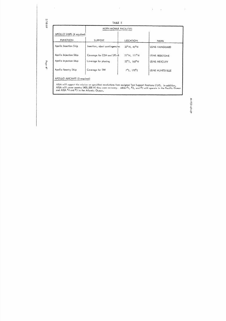
The MSFN is a worldwide communications network which is controlled by the MCCduring Apollo missions. The network is composed of fixed stationstfigure 15)and is
supplemented by mobile stations (Table 5) h’ hIC are optimally located within a globalband extending from approximately 40’ South latitude to 40’ North latitude. Stationcapabilities are summarized in Table 6.
The functions of these stations are to provide tracking, telemetry, command andcommunications both on an updata link to the spacecraft and on a down data link tothe MCC. Connection between these many MSFN stations and the MCC is providedby NASA Communications Network (NASCOM). M ore detail on Mission Support is
in the MOR Supplement.

8/8/2019 Apollo 9 Mission Operation Report
http://slidepdf.com/reader/full/apollo-9-mission-operation-report 56/230
75 6OW 45

8/8/2019 Apollo 9 Mission Operation Report
http://slidepdf.com/reader/full/apollo-9-mission-operation-report 57/230
75w 6OW 45w
,K-7y-
ST ATLANTIC

8/8/2019 Apollo 9 Mission Operation Report
http://slidepdf.com/reader/full/apollo-9-mission-operation-report 58/230
! ^--I--.,. _.. -
--- -..- -____

8/8/2019 Apollo 9 Mission Operation Report
http://slidepdf.com/reader/full/apollo-9-mission-operation-report 59/230
M-932-69-09
150E 165E I 80 165 N 15

8/8/2019 Apollo 9 Mission Operation Report
http://slidepdf.com/reader/full/apollo-9-mission-operation-report 60/230
150E 165E I 80 165;N 15ow 135w_... -_. . ..- __- ________I_’ ! I ----l-- -_- --- --- ------r ---y 45
iO:KKAICO : 1 i I! !
: .~. 1 I
I1 J
8/8/2019 Apollo 9 Mission Operation Report
http://slidepdf.com/reader/full/apollo-9-mission-operation-report 61/230
TABLE 5
MSFN MOBILE FACILITIES
APOLLO SHIPS (4 required)
FUNCTION SUPPORT LOCATION
Apollo Insertion Ship Insertion, abort contingencies 32’ N, 45OW
Apollo Injection Ship Coverage for CDH and SPS-8 22’N, 131°W
Apollo Injection Ship Coverage for phasing 22Os, 160°W
Apollo Reentry Ship Coverage for TPF 7’5, 170°E
APOLLO AIRCRAFT (5 required)
NAME
US NS VANGUARD
USNS REDSTONE
USNS MERCURY
USNS HUNTSVILLE
ARIA will support the mission on specified revolutions from assigned Test Support Positions (TSP). ln addition,ARIA wil I cover reentry (400,000 ft) thru crew recovery.and ARIA #4 and #5 in the Atlantic Ocean.
ARIA #l, #2, and #3 will operate in the Pacific Ocean
M-932-69-09
TABLE 6

8/8/2019 Apollo 9 Mission Operation Report
http://slidepdf.com/reader/full/apollo-9-mission-operation-report 62/230
TABLE 6
Network Configuration for the AS-504 Mission
-
W’IIS,7:X I
KIT--l-IlECEL--+i,>:,> I
tip---f
(_+I1_t-i-t
ic-!
M-932-69-09
8/8/2019 Apollo 9 Mission Operation Report
http://slidepdf.com/reader/full/apollo-9-mission-operation-report 63/230
RECOVERY SUPPORT PLAN
GENERAL
The primary responsibilities of the recovery forces in supporting the mission are:
A. Rapid location and safe retrieval of the flight crew and spacecraft.
B. The collection, preservation, and return of test data, test hardware, andinformation relating to the recovery operation.
This responsibility begins with lift-off and ends with safe return of the spacecraft andthe flight crew to a designated point within the continental United States. The SMwill probably break up during reentry and the landing areas will be chosen with thisin mind to prevent land impact of parts of the SM.
The recovery planning has been based upon an approximately IO-day duration missionwith recovery forces deployed in four recovery zones (1, 2, 3, and 4) as shown inFigure 16 with the primary landing area located in Zone 1. Table 7 provides a summaryof recovery forces.
The recovery will be directed from the Recovery Control Room of the MCC, and will besupported by two satellite recovery control centers: The Atlantic Recovery Centerlocated at Norfolk, Virginia, and the Pacific Control Center located at Kunia in theHawaiian Islands. In addition to the recovery control centers, there will be NASArepresentatives deployed with recovery forces throughout the worldwide DOD recoverynetwork, at vital staging bases, and in the landing areas to give on-scene technicalsupport to the DOD forces.
RECOVERY GUIDELINES

8/8/2019 Apollo 9 Mission Operation Report
http://slidepdf.com/reader/full/apollo-9-mission-operation-report 64/230
s NASA-S-68-6476
so RECOVERY ZONES, CONTINGENCY AREA ANDRECOMMENDED AIRCRAFT STAGING BASES
LPGEODETIC
rTITUDE, DEG
I’r’~“‘~‘l”‘l”‘r”~“~‘I~~‘I”~l’ I
a0
.&~ ~c&$ /
--!i- WEST PACIFICZONE 1
LONGITUDE, DEG
M-932-69-09

8/8/2019 Apollo 9 Mission Operation Report
http://slidepdf.com/reader/full/apollo-9-mission-operation-report 65/230
TABLE 7
RECOVERY FORCES, APOLLO 9
.
RECOVERYDESIGNATION
TYPE OF SHIPAND HULL NO. NAME OF SHIP
ATLANTIC OCEAN SHIPS
HOME PORT
PRS LPH-7
SRS-I AIS
SRS-2 LKA-54
G UADALCANAL NORFOLK
VANGUARD PORT CANAVERAL
ALGOL NORFOLK
SRS-3
SRS-4
SRS-5
PACIFIC OCEAN SHIPS
DD-852 MASON
DD-449 NICHO,LAS
DDG-2 1 COCHRANE
YOKOSUKA
PEARL
PEARL
78 HC-130 AIRCRAFT
M-932-69-09

8/8/2019 Apollo 9 Mission Operation Report
http://slidepdf.com/reader/full/apollo-9-mission-operation-report 66/230
C. Visibility - 3 nautical miles minimum
D. Wave Height - 8 feet maximum
RECOVERY AREAS
To define levels of recovery support, spacecra ft landing areas are discussed in fivegeneral categories: launch site, launch abort, primary, secondary, and contingency.Primary recovery ship support coverage will be required within the primary landingarea.
Launch Site Landina Area
A landing could occur in the launch site landing area (Figure 17) if an abort occurredbetween LES activation and T+90 seconds which corresponds to approximately 41 nauticalmiles downrange. T+90 seconds is the interface between the launch site recovery forcesand deep-water recovery forces. Launch site recovery forces, to the limit of theircapability, will support the deep-water recovery forces if such assistance is required.The possible CM landing points lie in a corridor within the launch site area. This
corridor, which is determined by the wind profile, will be defined at launch time.
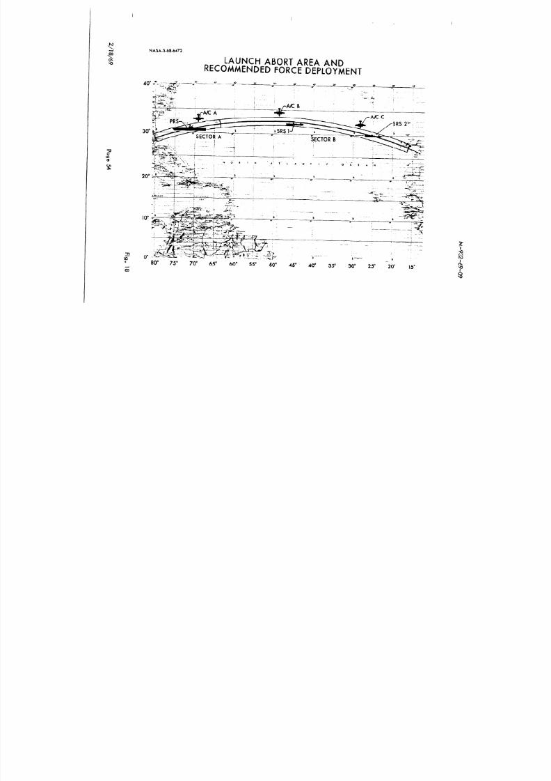
Launch Abort Landina Area
The launch abort landing area is the area in which the CM will land following an abortinitiated during the launch phase of flight (Figure 18). The launch abort landing areais a continuous area 50 nautical miles to either side of the ground track extending fromthe end of the launch site area to 3200 nautical miles downrange. It also includes an
area centered approximately 60 nautical miles south of the ground track at 3200 nauticalmiles downrange which encompasses the Mode Ill abort landing points. The requiredaccess time for aircraft for the launch abort areas is four hours. The retrieval time for
NASA-S-68-6463

8/8/2019 Apollo 9 Mission Operation Report
http://slidepdf.com/reader/full/apollo-9-mission-operation-report 67/230
n-.to.
;;j
LAUNCH SITE AREA AND RECOMMENDEDFORCE DEPLOYMENT
\ \ 1lNMI \
aA&A
HEAVYLIFTHELO
RECOVERYCOMMANDERSHELO
LVTR
LCU
FSK
NASA-S-68.bA72
8/8/2019 Apollo 9 Mission Operation Report
http://slidepdf.com/reader/full/apollo-9-mission-operation-report 68/230
NASA S 68.bA72
LAUNCH ABORT AREA ANDRECOMMENDED FORCE DEPLOYMENT
20”
10
22(0 0”.
z
, ;z- ,
---_1
.., _.--
-
-. .-
k k-7‘-80” 75~ 70” 65” 60” 55” 50” 45” 40” 35” 30” 25” ’
-2v 15”

8/8/2019 Apollo 9 Mission Operation Report
http://slidepdf.com/reader/full/apollo-9-mission-operation-report 69/230
NASA-S-68-6467
RECOMMENDED PRIMARY RECOVERY FORCE DEPLOYMENT
Landing ANA is an ellipseInscribed ufthin . 210 K 80
!;n rectangle centered st
lLACKOUl
n-.02.
M-932-69-09
8/8/2019 Apollo 9 Mission Operation Report
http://slidepdf.com/reader/full/apollo-9-mission-operation-report 70/230
Secondary Landing Area
A secondary landing area is an area in which a landing could occur after completion of
the launch phase when the primary landing area cannot be reached. The probability ofa landing in this area is sufficiently high to warrant a requirement for at least secondaryrecovery ship support. The majority of the secondary landing areas is located in thefollowing recovery zones:
ZONE
West AtlanticEast AtlanticWest PacificMid-Pacific
ZONE RADl USCENTER COORDINATES (N.Ml.)
28’N 60°W 24028’N 25’W 24028”N 140’E 24028”N 155”E 240
These zones are located so that generally there is a capability to land at a secondarylanding area once in every revolution.
Contingency Landing Area
The contingency landing area is that area outside the launch site, launch abort, primary,and secondary landing areas within which a landing could possibly occur, and requiringonly the support of land-based contingency aircraft. For Apollo 9 this includes all theearth’s surface between 34” North latitude and 34’ South latitude (outside the areasmentioned above). Although there is a remote possibility that an immedia te emergencyor catastrophic failure could result in a landing anywhere within these latitudes, it isexpected that most emergencies will permit sufficient time to delay the deorbit burn in
order to land at or near a preselected target point.
M -932-69-09

8/8/2019 Apollo 9 Mission Operation Report
http://slidepdf.com/reader/full/apollo-9-mission-operation-report 71/230
La jes Air Force Base (AFB) in the Azores; Tachikawa AB, Japan; Pago Pago, Samoa;Perth, Australia; Lima, Peru; the Ascension Islands; and the Mauritius Islands.Retrieval for a contingency area,landing will be an after-the-fact operation.
Target Points
A preferred target point (PTP) will be selected each revolution to provide a landingopportunity at a desirable location. If possible, the PTP will be chosen in one of thefour recovery zones supported by recovery ships and aircraft. If the ground track doesnot pass through a recovery zone,staging base.
the PTP will be chosen near a recovery aircraft
Alternate Target Points (ATP’s) will be selected approximately once every revolutionin such a manner that they occur halfway between PTP’s. As a result, there wil I be aPTP or an ATP approximately every 45 minutes during the flight. These preselectedaiming points will be as close to search/rescue aircraft staging bases as practicableafter considering such other things as weather,capability.
time of day of landing, and tracking
MOBILE QUARANTINE FACILITY (MQF) SIMULATION OPERATIONS
During the Apollo 9 mission, NASA desires to exercise as realistically as practicablethe Mobile Quarantine Facility (MQF) and its interfaces with the recovery forces. TheMQF is a mobile living facility, 35 feet long, 9 feet wide, and 9 feet high (Figure 20).It is specially designed to biologically isolate a flight crew during the recovery phaseof a lunar landing mission. For a lunar landing mission, the flight crew, one NASAflight surgeon, and one or two NASA support personnel will be biologically isolatedin the MQF during its transportation from the recovery area to the Lunar Receiving
Laboratory (LRL) at MSC. Although this exercise will be conducted concurrentlywith the Apollo 9 mission, it will in no way interfere with mission activities.
M-932-69-09

8/8/2019 Apollo 9 Mission Operation Report
http://slidepdf.com/reader/full/apollo-9-mission-operation-report 72/230
At this point in the second simulation, the normal routine planned for actual lunarlanding missions (including obtaining blood samples and passing samples and equipmentinto and out of the MQF) will be followed. This routine will be continued through theApollo 9 recovery and while the ship is enroute to Norfolk, Virginia.
At approximately 24 hours after recovery of Apollo 9, the USS Guadalcanal will arriveat Norfolk. The MQFand associated equipment will then be transferred to a C-141aircraft and flown to MSC. Upon arrival at MSC, the MQF will be transported to theLunar Receiving Laboratory (LRL) and a simulated docking and transfer into the labora-tory performed.exercise.
The operation will be terminated with an end-of-mission stowage
M -932-69-09

8/8/2019 Apollo 9 Mission Operation Report
http://slidepdf.com/reader/full/apollo-9-mission-operation-report 73/230
FLIGHT CREW
FLIGHT CREWASSIGNMENTS
Prime Crew (Figure 14)
Commander (CDR) - J. A. McDivitt (Colonel, USAF)Command Module Pilot (CMP) - D. R. Scott (Colonel, USAF)Lunar Module Pilot (LMP) - R. L. Schweickart (Civilian)
Backup Crew (Fig. 151
Commander (CDR) - C. Conrad (Commander, USN)Command Module Pilot (CMP) - R. F. Gordon (Commander, USN)Lunar Module Pilot (LMP) - A. L.Bean (Lieutenant Commander, USN)
PRIME CREW BIOGRAPHICAL DATA
Commander (CDR)
NAME: James A. McDivitt (Colonel, USAF)
DATE OF BIRTH: Born June 10, 1929, in Chicago, Illinois.
PHYSICAL DESCRIPTION: Brown hair; blue eyes; height: 5 feet, II inches;weight, 155 pounds.
EDUCATION: Graduated from Kalamazoo Central High School, Kalamazoo,Michigan; received a Bachelor of Science degree in Aeronautical
APOLLO 9 PRIME CREW

8/8/2019 Apollo 9 Mission Operation Report
http://slidepdf.com/reader/full/apollo-9-mission-operation-report 74/230
JAMES A. MC DIVITT
: ” -
DAVID R. SCOTT RUSSELL L. SCHWEICKART
2.
h

8/8/2019 Apollo 9 Mission Operation Report
http://slidepdf.com/reader/full/apollo-9-mission-operation-report 75/230
-h APOLLO 9 BACKUP CREW\o
-?I CHARLES CONRAD, JR.
93
ALAN L. BEAN RICHARD F. GORDON
M-932-69-09
EXPERIENCE: McDivitt joined the Air Force in 1951 and holds the rank of

8/8/2019 Apollo 9 Mission Operation Report
http://slidepdf.com/reader/full/apollo-9-mission-operation-report 76/230
EXPERIENCE: McDivitt joined the Air Force in 1951 and holds the rank ofColonel, He flew 145 combat missions during the Korean War in F-80’sand F-86s. He is a graduate of the USAF Experimental Test Pilot School
and the USAF Aerospace Research Pilot course and served as an experi-mental test pilot at Edwards Air Force Base, California.
CURRENT ASSIGNMENT: Colonel McDivitt was selected as an astronaut byNASA in September 1962.
He was command pilot for Gemini 4, a 66-orbit 4-day mission that beganJune 3 and ended on June 7, 1965. Highlights of the mission included
a controlled extravehicular activity period performed by pilot Ed White,cabin depressurization and opening of spacecraft cabin doors, and thecompletion of 12 scientific and medical experiments.
Command Module Pilot (CMP)
NAME: David R. Scott (Colonel, USAF)
DATE OF BIRTH: Born June 6, 1932, in San Antonio, Texas.
PHYSICAL DESCRIPTION: Blond hair; blue eyes; height: 6 feet; weight: 175pounds.
EDUCATION: Graduated from Western High School, Washington, D-C.;received a Bachelor of Science degree from the United States MilitaryAcademy and the degrees of Master of Science in Aeronautics and
Astronautics and Engineer in Aeronautics and Astronautics from theMassachusetts Institute of Technology.
M-932-69-09

8/8/2019 Apollo 9 Mission Operation Report
http://slidepdf.com/reader/full/apollo-9-mission-operation-report 77/230
Upon completing this tour of duty, he returned to the United States forstudy at the Massachusetts Institute of Technology where he completedwork on his Master’s degree.
His thesis at MIT concerned interplanetarynavigation.
After completing his studies at MIT in June 1962, he attended theAir Force Experimental Test Pilot School and then the AerospaceResearch Pilot School.
CURRENT ASSIGNMENT: C o one1 Scott was one of the third group of astronautsnamed by NASA in October 1963. On March 16, 1966, he andCommand Pilot Neil Armstrong were launched on the Gemini 8 mission--a flight originally scheduled to last three days but terminated early dueto a malfunctioning OAMS thruster. The crew performed the firstsuccessful docking of two vehicles in space and demonstra ted greatpiloting skill in overcoming the thruster problem and bringing thespacecraft to a safe landing.
Lunar Module Pilot (LMP)
NAME: Russel L. Schweickart (Civ.)
DATE OF BIRTH: Born October 25, 1935, in Neptune, New Jersey.
PHYSICAL DESCRIPTION: Red hair; blue eyes; height: 6 feet;weight: 161 pounds.
EDUCATION: Graduated from Manasquan High School, New Jersey; receiveda Bachelor of Science degree in Aeronautical Engineering and a Master
M-932-69-09

8/8/2019 Apollo 9 Mission Operation Report
http://slidepdf.com/reader/full/apollo-9-mission-operation-report 78/230
BACKUP CREW BIOGRAPHICAL DATA
Commander (CDR)
NAME: Charles Conrad, Jr. (Commander, USN)
DATE OF BIRTH: Born on June 2, 1930, in Philadelphia, Pennsylvania.
PHYSICAL DESCRIPTION: Blond hair; blue eyes; height: 5 feet ,6 l/2 inches;weight: 138 pounds.
EDUCATION: Attended primary and secondary schools in Haverford, Pennsylvania,and New Lebanon, New York; received a Bachelor of Science degree inAeronautical Engineering from Princeton University in 1953 and anHonorary Master of Arts degree from Princeton in 1966.
ORGANIZATIONS: Member of the American Institute of Aeronautics andAstronautics and the Society of Experimental Test Pilots.
SPECIAL HONORS: Awarded two Distinguished Flying Crosses, two NASAExceptional Service Medals, and the Navy Astronaut Wings; recipient ofPrinceton’s Distinguished Alumnus Award for 1965, and the AmericanAstronautical Society Flight Achievement Award for 1966.
EXPERIENCE: Conrad entered the Navy following his graduation from PrincetonUniversity and became a naval aviator. He attended the Navy Test PilotSchool at Patuxent River, Maryland, and upon completing that course ofinstruction was assigned as a project test pilot in the armam ents testdivision there. He also served at Patuxent as a flight instructor and
M-932-69-09

8/8/2019 Apollo 9 Mission Operation Report
http://slidepdf.com/reader/full/apollo-9-mission-operation-report 79/230
Command Module Pilot (CMP)
NAME: Richard F. Gordon, Jr. (Commander, USN)
DATE OF BIRTH: Born October 5, 1929, in Seattle, Washington.
PHYSICAL DESCRIPTION: Brown hair; hazel eyes; height: 5 feet 7 inches;weight: 150 pounds.
EDUCATION: Graduated from North Kitsap High School, Poulsbo, Washington;received a Bachelor of Science degree in Chemistry from the Universityof Washington in 1951.
ORGANIZATIONS: Member of the Society of Experimental Test Pilots.
SPECIAL HONORS: Awarded two Distinguished Flying Crosses, the NASAExceptional Service Medal, and the Navy Astronaut Wings.
EXPERIENCE: Gordon, a Navy Commander, received his wings as a navalaviator in 1953. He then attended All -Weather Flight School and iettransitional training and was subsequently assigned to an all-weatherfighter squadron at the Naval Air Station at Jacksonville, Florida.
In 1957, he attended the Navy’s Test Pilot School at Patuxent River,Maryland, and served as a flight test pilot until 1960.
He served with Fighter Squadron 121 at the Miramar, California, NavalAir Station as a flight instructor in the F4H and participated in theintroduction of that aircraft to the Atlantic and Pacific Fleets. Winner
-
M -932-69 -09
L M d l Pil t (LMP)

8/8/2019 Apollo 9 Mission Operation Report
http://slidepdf.com/reader/full/apollo-9-mission-operation-report 80/230
Lunar Module Pilot (LMP)
_-
NAME: Alan L. Bean (Lieutenant Commander, USN)
DATE OF BIRTH: Born in Wheeler, Texas, on March 15, 1932.
PHYSICAL DESCRIPTION: Brown hair; hazel eyes; height: 5 feet, 9 l/2 inches;weight, 155 pounds.
EDUCATION: Graduated from Paschal High School in Fort Worth , Texas;received a Bachelor of Science degree in Aeronautical Engineeringfrom the University of Texas in 1955.
ORGANIZATIONS: Member of the Society of Experimental Test Pilots and DeltaKappa Epsi Ion.
EXPERIENCE: Bean, a Navy ROTC student a t Texas, was commissioned upongraduation in 1955. Upon completing his flight training, he was assignedto Attack Squadron 44 at the Naval Air Station in Jacksonville, Florida,for four years. He then attended the Navy Test Pilot School at PatuxentRiver, Maryland. Upon graduation he was assigned as a test pilot at theNaval Air Test Center, Patuxent River. He attended the school ofAviation Safety at the University of Southern California and was nextassigned to Attack Squadron 172 at Cecil Field, Florida.
CURRENT ASSIGNMENT: Lt. Commander Bean was one of the third group ofastronauts selected by NASA in October 1963. He served as backupCommand Pilot for the Gemini 10 mission.
M-932-69-09
MISSION MANAGEMENT RESPONSIBILITY

8/8/2019 Apollo 9 Mission Operation Report
http://slidepdf.com/reader/full/apollo-9-mission-operation-report 81/230
MISSION MANAGEMENT RESPONSIBILITY
Title
Director, Apollo Program
Name
Lt. Gen. Sam C. Phillips
Director, Mission Operations Mai. Gen. John D. Stevenson (Ret)
Saturn V Vehicle Prog. Mgr. Mr. Lee B. James
Apollo Spacecraft Prog. Mgr. Mr. George M. Low
Apol lo Prog. Manager KSC R. Adm. Roderick 0. Middleton
Mission Director Mr. George H. Hage
Assistant Mission Director Capt. Chester M. Lee (Ret)
Assistant Mission Director Col . Thomas H. McMullen
- Director of Launch Operations Mr. Rocco Petrone
Director of Flight Operations Mr. Christopher C. Kraft
Launch Operations Manager Mr. Paul C. Donnelly
Flight Directors Mr. Eugene F. Kranz
Mr. Gerald D. GriffinMr. M. P. Frank
Oraanization
NASA/OMS F
NASA/OMSF
NASA/MS FC
NASA/MSC
NASA/KSC
NASA/OMSF
NASA/OMSF
NASA/OMS F
NASA/KSC
NASA/MSC
NASA/KSC
NASA/MSC
M-932-69-09

8/8/2019 Apollo 9 Mission Operation Report
http://slidepdf.com/reader/full/apollo-9-mission-operation-report 82/230
PROGRAM MANAGEMENT
NASA HEADQUARTERS
Office of Manned Space Flight
Manned Spacecraft Center
Marshall Space Flight Center
Kennedy Space Center
.-
LAUNCH VEHICLE SPACECRAFT TRACKING AND DATAACQUISITION
Marshall Space Flight Center Manned Spacecraf t Kennedy Space CenterThe Boeing Co. (S-IC) CenterNorth American Rockwe I I North American Goddard Space Flight Center
Corp. (S-l I) Rockwel I (LES,McDonnel I Douglas Corp. CSM, SLA) Department of Defense
(S-IVB) Grumman AircraftIBM Corp. (IU) Engineering Corp.
( lMSFN
M-932-69-09
ABBREVIATIONS
8/8/2019 Apollo 9 Mission Operation Report
http://slidepdf.com/reader/full/apollo-9-mission-operation-report 83/230
ABBREVIATIONS
.-
AGSAKAPSAPSASATPCCATSCDHCDR
CESCFPCMCMPCOICSICSM
c/TDAPDODDPSDSDTOECSEDSEPS
EVAGET
Abort Guidance SystemApogee Kit kAscent Propulsion System (LM)Auxiliary Propulsion System (S-IVB)Ascent StageAlternate Target PointCommunications, Command, and Telemetry SystemConstant Delta HeightCommander
Central Electronics SystemConcentric FI ight PlanCommand ModuleCommand Module PilotContingency Orbit InsertionConcentric Sequence InitiationCommand Service ModuleCrawler Transporter
Digital Auto PilotDepartment of DefenseDescent Propulsion SystemDescent StageDetailed Test ObjectivesEnvironmental Control SystemEmergency Detection SystemElectrical Power System
Extravehicular ActivityGround Elapsed Time
M-932-69-09

8/8/2019 Apollo 9 Mission Operation Report
http://slidepdf.com/reader/full/apollo-9-mission-operation-report 84/230
LOXLRLLTALVMCCMOCRMQFMTVCOMS FPGAPG NCSPTPRCSRFRSORTCCS&AscsSEQSLASMSPSsvSXTTBTD&ETLI
Liquid OxygenLunar Receiving LaboratoryLunar Module Test ArticleLaunch VehicleMission Control CenterMission Operations Control RoomMobile Quarantine FacilityManual Thrust Vector ControlOffice of Manned Space FlightPressure Garment AssemblyPrimary Guidance, Navigation, and Control SystemPreferred Target PointReaction Control SystemRadio FrequencyRange Safety OfficerReal Time Computer ComplexSafe and ArmStabilization and Control SystemSequential SystemSpacecraft LM AdapterService ModuleService Propulsion SystemSpace VehicleSextantTime BaseTransposition, Docking, and EjectionTrans Lunar Injection
Post LaunchMission Operation ReportNo. M-932-69-09

8/8/2019 Apollo 9 Mission Operation Report
http://slidepdf.com/reader/full/apollo-9-mission-operation-report 85/230
MEMORANDUM
To: A/Ad ministrator
6 May 1969
From: MA/Apollo Program Director
% Subject: Apollo 9 Mission (AS-504) Post Launch Report # 1
The Apollo 9 mission was successfully launched from the Kennedy Space Center onMonday, 3 March 1969 and was completed as planned, with recovery of the spacecraftand crew in the Atlantic recovery area on Thursday, 13 March 1969. Initial evaluationof the flight, based upon quick-look data and crew debriefing, indicates that all missionobjectives were attained. Further detailed analysis of all data is continuing and appro -priate refined results of the mission will be reported in Manned Space Flight Centertechnical reports.
Based on the mission performance as described in this report, I am recommending thatthe Apollo 9 mission be adjudged as having achieved agency preset primary objectivesand be considered a success.
Apol lo Program Director
Report No. M-932-69-09

8/8/2019 Apollo 9 Mission Operation Report
http://slidepdf.com/reader/full/apollo-9-mission-operation-report 86/230
M-932-69-09
GENERAL
8/8/2019 Apollo 9 Mission Operation Report
http://slidepdf.com/reader/full/apollo-9-mission-operation-report 87/230
The Apollo 9 (AS-504) mission was the first manned flight involving the Lunar Module.
The crew were James A. McDivitt, Commander; David R. Scott, Command ModulePilot; and Russell L. Schweickart, Lunar Module Pilot. Launch had been initially
scheduled for 28 February 1969, but was postponed for three days because all three
crewmen had virus respiratory infections. The countdown was accomplished without
any unscheduled holds and the AS-504 Space Vehicle was successfully launched from
Launch Complex 39 at Kennedy Space Center, Florida, on Monday, 3 March 1969.
Recovery of the flight crew and Command Module was successfully accomplished on
13 March 1969, for a flight duration of 241 hours 53 seconds.
Initial review of test data indicates that overall performance of the launch vehicle,
spacecraft, and flight crew together with ground support and control facilities and
personnel was satisfactory, and that all primary mission objectives were accomplished.
M-932-69-09
NASA OMSF PRIMARY MISSION OBJECTIVES
FOR APOLLO 9

8/8/2019 Apollo 9 Mission Operation Report
http://slidepdf.com/reader/full/apollo-9-mission-operation-report 88/230
FOR APOLLO 9
PRIMARY OBJECTIVES
. Demonstrate crew/space vehicle/mission support facilities performance during
a manned Saturn V mission with CSM and LM.
. Demonstrate LM/crew performance.
. Demonstrate performance of nominal and selected backup Lunar Orbit
Rendezvous (LOR) mission activities, including:
Transposition, docking, LM withdrawal
Intervehicular crew transfer
Extravehicular capability
SPS and DPS burns
LM actiQe rendezvous and docking
CSM/LM consumables assessment.
i’
($dot$e E. Mueller
Lt. General, ‘USAF ,,&sociate Administrator for
Apollo Program Director Manned Space Flight
Date: 14 FEB 67 Date:
M-932-69-09
COUNTDOWN

8/8/2019 Apollo 9 Mission Operation Report
http://slidepdf.com/reader/full/apollo-9-mission-operation-report 89/230
The terminal countdown for Apollo 9 began at T-28 hours at 10:00 p.m. EST, 1 March
1969. The only holds encountered were two planned holds: one at T-16 hours for3 hours, and one at T-9 hours for 6 hours. The count was resumed for the last time at
2:00 a.m. EST, 3 March 1969, and proceeded to launch at 11:00:00 a.m. EST.
FLIGHT SUMMARY,
The Apollo 9 mission was launched from Kennedy Space Center, Florida, at 11:OO:OO
a.m. EST, 3 March 1969. All launch vehicle stages performed satisfactorily, but
burned slightly longer than planned, inserting the S-IVB/spacecraft combination into
a nominal orbit of 102.3 by 103.9 nautical miles (NM).
After post-insertion checkout was completed, the Command/Service Module (CSM)was separated from the S-IVB, transposed, and docked with the Lunar Module (LM).
The docked spacecraft was separated from the S-IVB at 4:08:05 GET (Ground Elapsed
Time). After separation, two unmanned S-IVB burns were performed to place the S-IVB/
Instrument Unit on an earth-escape traiectory. After the third burn, the planned pro-pellant dumps could not be performed.
After spacecraft separation from the launch vehicle, four Service Propulsion System
(SPS) firings were made with the CSM/LM docked.
At approximately 43.5 hours GET, the Lunar Module Pilot (LMP) and the Commander(CDR) transferred to the LM. The first manned firing of the LM Descent Propulsion
System (DPS) was initiated about 6 hours later. The two crewmen then returned to theCommand Module (CM) for the fifth SPS firing.
At approximately 70 hours GET, the LMP and CDR again transferred to the LM for the
M-932-69-09
The sixth SPS firing, to lower apogee, was delayed because the +X translation to
precede the maneuver was not programmed properly However the maneuver was

8/8/2019 Apollo 9 Mission Operation Report
http://slidepdf.com/reader/full/apollo-9-mission-operation-report 90/230
precede the maneuver was not programmed properly. However, the maneuver wasrescheduled and successfully completed in the next revolution.
During the last three days, a seventh SPS firing was made to raise the apogee, andthe SO65 Multispectral Photography Experiment and landmark tracking were accomplished.
Unfavorable weather in the planned landing area caused the deorbit maneuver (SPS 8)
to be delayed for one revolution. This decision was made the day before splashdown
and recovery forces were redeployed. Final parachute descent and splashdown werewithin sight of the prime recovery ship in the Atlantic Ocean. Splashdown was near
the target point of 23 degrees 15 minutes north latitude, 68 degrees west longitude,as determined from the onboard computer solution. The crew were safely aboard the
prime recovery ship, USS Guadalcanal, within 1 hour of splashdown.
Table 1 presents a summary of mission events.
TABLE 1
SUMMARY OF MISSION EVENTS
EVENT
First Motion
Maximum Dynamic Pressure
S IC C t E i C t ff
TIME (GET)HR: MIN: SEC
PLANNED* ACTUAL
oo:oo:oo oo:oo:oo
0o:o 1:2 1 0O:O 1:26
00 02 14 00 02 14
Jettison Launch Escape Tower 00:03: 16
M-932-69-09
00:03:18

8/8/2019 Apollo 9 Mission Operation Report
http://slidepdf.com/reader/full/apollo-9-mission-operation-report 91/230
S-II Engine Cu toff Command
S-II/S-IVB Separation
S-IVB Engine Ignition
S-IVB Engine Cutoff
Parking Orbit Insertion
Separation and Docking Maneuver Initiation
Spacecraft Docking
Spacecraft Final Separation
S-IVB Restart Preparation
- S-IVB Reignition (2nd Burn)
S-IVB Second Cutoff Signal
S-IVB Restart Preparations
SPS Burn 1
S IVB Reignition (3rd Burn)
00:08:5 1
00:08:52
00:08:55
00: 10:49
00: 10:59
02:33:49
03:05:00
(Approx)
04:08:57
04:36: 12
04:45:50
04~46~52
05:59:35
06:O 1:40
06:07: 13
00:08:56
00:08:57
00: 09:Ol
00: 11:05
00:11:15
02:41 :16
03:01:59.\
04:08:06
04:36: 17
04:45:56
04:46:58
05:59:4 1
05:59:01
06:07: 19
M-932-69-09
SPS Burn 4 28:28:00 28:24:41

8/8/2019 Apollo 9 Mission Operation Report
http://slidepdf.com/reader/full/apollo-9-mission-operation-report 92/230
.
Docked DPS Burn
SPS Burn 5
Undocking
CSM/LM Separation
DPS Phasing
DPS Insertion
Concentric Sequence Initiation - LM RCS Burn
Constant Delta He ight - APS Burn
Terminal Phase Initiation
CSM/LM Docking
APS Burn to Propellant Depletion
49:42:00
54:25:19
92:39:00
93:07:40
93:5 1:34
95:43:22
96~2 1:00
97:05:27
98:00: 10
99: 13:oo
hv-o4
101:.58:00
SPS Burn 6 12 1:58:48
SPS Burn 7 169:47:54
SPS Burn 8 (Deorbit) **
49:4 1:35
54:26: 12
92:39:36
93:02:54
93:47:35
95:39 :08
96:16:07
96:58 : 15
97:57:59
99:02:26
101:53:15
123:25:07
169: 39:00
240:31 :15
M-932-69-09
MISSION PERFORMANCE

8/8/2019 Apollo 9 Mission Operation Report
http://slidepdf.com/reader/full/apollo-9-mission-operation-report 93/230
The significant portions of the Apollo 9 mission are discussed herein. Space vehicle
systems and mission support performance are covered in succeeding sections.
TRAJECTORY
The CSM/LM/IU/S-IVB combination was inserted into earth orbit at 0O:ll: 15 GET after
a normal launch phase. The resulting orbital elements and maneuver parameters aregiven in Table II for all engine firings.
Four SPS maneuvers were performed prior to the first docked DPS firing. Each of thefirst three SPS maneuvers was made without requiring a +X translation to settle propel-
lants. The fourth SPS maneuver was preceded by an 18-second +X translation madewith the Service Module Reaction Control System (SM RCS).
The fifth docked SPS maneuver resulted in the perigee being approximately 5 NM lessthan planned causing the rendezvous to be initiated 4 minutes earlier. Small cutofferrors of this magnitude were expected, and real-time trajectory planning for both
rendezvous and deorbit was conducted to accommodate minor adjustments in theinitiation times and velocity increments. Out-of-plane components were added during
the flight to certain preplanned maneuvers to provide substantial reduction in space-
craft weight without significantly changing the orbital parameters for subsequentmaneuvers.
The trajectory aspects of the rendezvous exercise will be discussed in the rendezvous
section.
After the Ascent Stage jettison, a separation maneuver of 3 feet per second (fps) was
f d b h SM RCS Th APS i h fi d ll d l i
TTABLE II SUMMARYOFMAN EUVERS
BURN TIME (SECONDS)--
*Prelaunch teal Time Prelaunct Real TimePLANNEC ‘LANNED ACTUAL ‘LANNECPLANNEC ACTUAL
OV (FEET PER SECOND) T RESULTANT ORBIT
‘Prelauncl Real TimePLANNEf PLANNEI ACTUAL

8/8/2019 Apollo 9 Mission Operation Report
http://slidepdf.com/reader/full/apollo-9-mission-operation-report 94/230
First Service Propulsio n
Second Service Propulsion 111.3 111.2 110.3 849.6 850.6 850.5
Third Service Propulsion 280.0 281.9 279.9 1548.2 2570.7 2567.9
Fourth Service Propulsion 28.1 28.4 27.9 299.4 300.9 300.5
First Descent Propulsion 367.0 370.6 372.0 734.0 1744.0 1737.5
Fifth Service Propulsion 41.5 43.2 43.3 552.3 575.4 572.5
Ascent Propulsion Firingto Depletion
389.0** 444.9** 362.4 >074.9** 7427.5** 5373.4
Sixth Service Propulsion 2.4 1.33 1.40 62.7 38.8 33.7
Seventh Service Propulsion 9.9 25.0 24.9 252.8 653.3 650.1
241.8X
-15.1Eighth Service Propulsion 11.7 11.6 11.7 323.3 325.0 322.7
--
NOTES: * Prelaunch planned refers to Apollo 9 Spacecraft Operational Trajectory, Revision 2, 20 February 1969.** APS burn to depletion planned for unattainable apogee value to insure propellant depletion cutoff,
--
5.0 4.96 5.2 36.8 36.8 36.6125.2 128.2 127.6
X X X108.7 110.2 111.3
190.2 189.8 192.5X X X
109.1 107.7 110.7
268.2 270.3 274.9X X X
111.3 109.4 112.6
268.7 273.8 275.0X X X
111.4 109.3 112.4
267.6 269.9 274.6X X X
111.8 109.1 112.1
130.2 129.8 131 .oX X X
129.7 129.8 125.9
4673.3 6932.3 3760.9X x X
128.9** 125.9 126.6
127.9 120.2 123.1X X X
94.6 104.8 108.5
238.7 250.4 253.2X X X
93.9 97.9 100.7
238.5X
---
240.0
J.7
M-932-69-09
EXTRAVEHICULAR ACTIVITY

8/8/2019 Apollo 9 Mission Operation Report
http://slidepdf.com/reader/full/apollo-9-mission-operation-report 95/230
Extravehicular activity (EVA), pianned for the third day, was reduced from 2 hours
15 minutes to about 1 hour of depressurized LM activity. This change was made be-
cause the LMP experienced a minor in-flight illness during the first two days of the
mission.
Preparation for EVA began at approximately 71 hours GET. The CDR and the LMP werein the LM and the CMP in the CM. At approximately 73 hours GET, after donning the
Portable Life Support System (PLSS) and the Oxygen Purge System (OPS), the LMP
egressed through the forward hatch and moved to the external foot restraints on the
platform. During this time the CM was depressurized and the side hatch was opened.Thermal sample retrieval was photographically recorded with the sequence cameras.
The LMP used the handrails to evaluate body control and transfer techniques. Ingress
was completed at about 74 hours GET. Both hatches were then secured and the vehicles
repressurized. The PLSS was successfully recharged with oxygen and water.
The lithium hydroxide cartridge from the system was returned to the CM for post-flight
metabolic analysis.
The repressurization cycles for both vehicles were nominal, and post-EVA procedures
were followed without difficulty.
RENDEZVOUS
The CDR and the LMP transferred to the LM on the fifth day for the rendezvous. The
rendezvous exercise began on schedule with a 5-fps separation maneuver using the
SM RCS.
A phasing maneuver of 90 5 fps was performed with the LM DPS about 2 8 NM from
M-932-69-09
LM rendezvous navigation and maneuver targeting using both the primary and the backup
guidance systems were satisfactory. Radar data were successfully used, both automatically
by the primary system and through manual insertion in the About Guidance System to

8/8/2019 Apollo 9 Mission Operation Report
http://slidepdf.com/reader/full/apollo-9-mission-operation-report 96/230
by the primary system and through manual insertion in the About Guidance System, tocorrect rendezvous state vet tors. Maneuver solutions from both onboard systems and from
ground computations appeared to correlate closely. The crew selected the primary syitem
solutions for all maneuvers through the first midcourse correction performed after terminalphase initiation.
Rendezvous navigation and mirror-image targeting in the CM were performed satisfactorily;
however, loss of th,e LM tracking light prevented sextant measurements from the CM when
both vehicles were in darkness. Preliminary data indicate that CM maneuver calculations
for terminal phase initiation were satisfactory.
FLIGHT CREW PERFORMANCE
Crew performance was excellent througho ut the mission, and the flight was conducted
essentially in accordance with the nominal plan.
Preparation for transfer to the LM required longer than anticipated, primarily because
of the time required for the crewmen to don the space suits. The suit supply hoses were
a source of interference and also contributed to the longer preparation time. As aresult, about 1 hour was added to the preparation time for subsequent transfers.
Visual and photographic inspection of the entire spacecraft was accomplished afterrendezvous and before docking.
FLIGHT CREW BIOMEDICAL EVALUATION
The launch was postponed for 72 hours because of symptoms of upper respiratory in-fections in all three crewmen. Physical examinations 3 hours before launch revealed
M-932-69-09
FLIGHT CONTROL
Flight control performance was satisfactory in providing operational support for the
8/8/2019 Apollo 9 Mission Operation Report
http://slidepdf.com/reader/full/apollo-9-mission-operation-report 97/230
Flight control performance was satisfactory in providing operational support for the
Apollo 9 mission. Minor spacecraft problems were encountered , but none was such
that either the mission operations or the flight plan was significantly altered.
Early in the mission, a caution and warning light on Hydrogen Tank 1 was observed
just prior to an automatic cycle of the heaters. This condition persisted and the crewhad to be disturbed during a rest period at 81 hours GET to increase the hydrogen tank
pressure.
On the third day, the crew were about 1 hour behind the timeline, resulting in
cancelling all the planned communications tests except the LM secondary S-band test
and the LM two-way relay with television.
On the fourth day, the EVA was abbreviated and the external transfer from the LM tothe CM was not performed . The activity was restricted to the LM forward platformbecause of concern about the LMP’s earlier illness and proper readiness for the rendezvous
on the following day.
At approximately 78 hours GET, after the tunnel hardware had been installed, acrewman made an unplanned return to the LM to open a circuit breaker. This change
shortened the rest period about 30 minutes.
On the fifth day, LM activation was performed approximately 40 minutes early to insure
an on-time rendezvous initiation.
The LM VHF telemetry and S-band power amplifier were lost for 6 and 12 hours,
respectively, after the APS firing to depletion. These failures were expected because
f h l k f li Th l t i l t bilit f thi ft l
M-932-69-09
RECOVERY

8/8/2019 Apollo 9 Mission Operation Report
http://slidepdf.com/reader/full/apollo-9-mission-operation-report 98/230
Recovery of the Apollo 9 Command Module and crew was completed in the West
Atlantic by the prime recovery ship, USS Guadalcanal. The following table is a
list of significant recovery events on 13 March 1969:
EVENT
First VHF contact
EST
11:51 a.m.
First beacon and voice contact 11:57 a.m.
First visual contact 11:59 a.m.
Landing 12:Ol p.m.
Swimmers deployed 12:07 p.m.
Flotation collar installed 12:14 p.m.
CM hatch open 12:27 p.m.
First astronaut aboard helicopter 12:39 p.m.
All astronauts in helicopter 12:46 p.m.
Astronauts on deck 12:50 p.m.
TABLE Ill
LAUNCH VEHICLE DISCREPANCY SUMMARY
DESCRIPTION REMARKS

8/8/2019 Apollo 9 Mission Operation Report
http://slidepdf.com/reader/full/apollo-9-mission-operation-report 99/230
Oscillations occurred in the S-II center engine chamberpressure and the S-II structure late in the burn. Osci I-
lations have occurred on four flights and five static
firings, but only after 320 seconds of S-II burn.
S-IVB APS Module No. 2 helium supply pressure decayec
slowly.
S-IVB helium regulator lock-up pressure exceeded the
redline during countdow n, and the helium pneumatic
pressure was high throughout the mission.
S-IVB third burn anomaly: Gas generator pressure spike
at start, engine chamber pressure oscillations, loss of
engine control pneumatic pressure, abnormal attitude
control system oscillations, decrease in engine perfor-
mance during burn, and inability to dump residual
propellants after burn.
Apparently caused by coupling between the center engineand the stage structure. Fix will be early center enginecutoff at 299 seconds on Apollo 10.
Leak in teflon seals upstream of the regulator. Change
of seal material to rubber has been approved. Closed.
Internal leakage in regulator caused by wear on poppet.
Modified regulator has been tested and installed on
S-IVB-505. Redline has been raised from 585 to 630 psi.
Caused by extreme out-of-spec engine start conditions
which resulted in excessive engine chamber pressure
oscillations and possible gas generator damage, followed
by loss of pneumatic system. There is no evidence that
the causes of this anomaly are applicable to an in-spec
engine start. The flight mission rules allowing restart
with recircula tion systems inoperative are being revisedfor Apollo 10.
TABLE IV
COMMAND/SERVICE MODULE DISCREPANCY SUMMARY
DESCRIPTION REMARKS

8/8/2019 Apollo 9 Mission Operation Report
http://slidepdf.com/reader/full/apollo-9-mission-operation-report 100/230
Unable to translate the CSM to the left. Propellant
isolation valves in two SM RCS quads were found to beclosed.Master alarm occurred coincident with hard docking with-
out any accompanying annunciator.
During the third SPS burn, eight master alarms occurredbecause of indications of propellant unbalance.
The scanning telescope mechanism jammed frequently when
driven manually, but worked normally in automatic mode.
Fuel Cell No. 2 condenser outlet temperature exceeded
the normal range several times,
Automatic control of the pressure in the cryogenic
hydrogen tanks was lost and pressure was controlled
manually.The first two attempts to undock were unsuccessful because
the release switch was not held long enough. Before the
2nd docking, the “flag” check showed the capture latcheson the probe were not cocked; recycling the switch pro-
duced a cocked indication.
Apparently caused by mechanical shock at CSM/S-IVB
separation. The crew will check the valve positions afterseparation on Apollo 10 and subsequent missions.
Caused by a sensor transient or a momentary short circuit
due to mechanical shock. Also occurred during the CSM106 docking test.
Caused by erroneous readings from the primary probe in theSPS oxidizer tank. The master alarm and warning function
from the PUGS have been deleted on CSM 106 and
subsequent spacecraft. Closed.
A pin from a counter drum was found wedged in a split
gear. Units on Apollo 10 and subs will be replaced with
units that have been inspected. Closed.
The bypass valve that control s coolan t temperature operates
improperly because of contamination in the glycol. For
subsequent missions, Block I valves which are less suscep-
tible to contaminants will be installed and the radiatorswill be vibrated and flushed 30 to 45 days before launch.
Closed.
Probably caused by an intermittent open circuit in the
motor switch control circiut. No hardware change will
be made, Closed.
The Apollo Operations Handbook has been revised toclarify the procedure for extending the probe. Closed.
TABLE IV (CONTINUED)
DESCRIPTION
CSM would not respond to multiple uplink realtime com-
mands for about 10 hours; only the first command was
REMARKS
Caused by flight hardware associated with the message-
acceptance pulse.

8/8/2019 Apollo 9 Mission Operation Report
http://slidepdf.com/reader/full/apollo-9-mission-operation-report 101/230
accepted. The problem was cleared by cycling the up-
telemetry command reset switch.The CM computer failed twice to respond properly to
programs entered by DSKY. The ground verified correct
loading except for the last entry, which is not monitored.
The entry monitor system scribe did not continuously cut
through the emulsion on the scroll during entry.
After recovery, one docking ring separation charge holder
was out of its channel far enough to possibly foul or cut
the oarachute riser lines durina deployment.
Probably caused by procedural error in making the last
entry on the DSKY. Closed.
Caused by a leak in the scroll assembly which causedhardening of the emulsion. On Apollo 10, the scrol I
assembly will be leak tested a nd a sharper stylus wil l be
used. Closed .
A spring has been incorporated to retain the charge holderson CM 106 and subsequent spacecraft. Closed.
DESCRIPTION REMARKS
During the first 30 seconds of the 1st DPS burn, the super- Flow was probably blocked momentarily by freezing of air
TABLE V
LUNAR MODULE DISCREPANCY SUMMARY

8/8/2019 Apollo 9 Mission Operation Report
http://slidepdf.com/reader/full/apollo-9-mission-operation-report 102/230
g , p p y y y g
critical helium regulator manifold pressure dropped to 180 or other contaminants in the supercritical helium tank heatpsia and then recovered to a normal 240 psia. An anoma- exchanger. Servicing equipment and procedures have been
lous pressure rise also occurred during prelaunch servicing. revised. Closed.
The DPS supercritical helium tank pressure began decaying Possible leak upstream of the solenoid latch valve. The
at the end of the 1st DPS burn at a rate indicating a LM-4 flight configuration will be checked to assure ade-
0.1 lb/hr leak. quate strength margins for thermal, vibration, and squib
valve firing shock. The squib valve braze joints will a lso
be tested.
The oxygen purge system light did not come on during a Failure of the main power switch actuator mechanism,
self-test prior to rendezvous, after being erratic earlier. which has been redesigned for Apollo 10 and subs. Closed,
The LMP’s push-to-talk switches on the umbilical and on Probably caused by a discontinuity (broken wire) in the
the attitude controller were inoperative after about 89 common wire to the push-to-talk switches which are inhours GET. LMP used the VOX mode for remainder of LM parallel. Closed.
operations,
The abort guidance system (AGS) warning light remained Probably a malfunction of the caution and warning
on continuously in standby and operating modes during circuitry, but the failure mode cannot be identified
period five. The AGS operated nominally throughout the because the AGS parameters are not displayed or
mission. telemetered. Closed.
ne DPS engine was rough for a few seconds at 27% Caused by helium trapped in the propellant lines duringthrottle during the second DPS burn. the previous SPS burns, which has no detrimental effect on
the system. Closed.
The tracking light failed during ascent/descent staging. Probably caused by a failure in the pulse forming network.Mission simulations are being run on the LM-4 light.
TABLE V (CONTINUED
DESCRIPTION REMARKS
The Crewman Optical Alignment Sight (COAS) re IC e was Background light washed out the reticle image. On LM-4’ I
difficult to see during rendezvous and subsequent LM’s, the light filter will be replaced
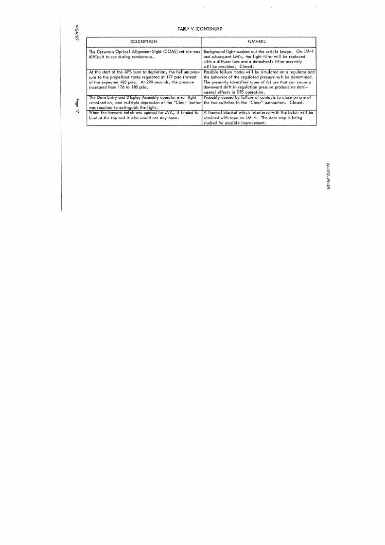
8/8/2019 Apollo 9 Mission Operation Report
http://slidepdf.com/reader/full/apollo-9-mission-operation-report 103/230
difficult to see during rendezvous. and subsequent LM s, the light filter will be replaced
with a diffuser lens and a detachable filter assembly
will be provided. Closed.
At the start of the APS burn to depletion, the helium pres- Possible failure modes will be simulated on a regulator and
sure to the propellant tanks regulated at 177 psia instead the behavior of the regulated pressure w ill be determined.
of the expected 185 psia. At 290 seconds, the pressure The presently identified types of failure that can cause a
increased from 176 to 180 psia. downward shift in regulation pressure produce no detri-
mental effects in DPS operation.
remained on, and multiple depression of the “Clear” button the two switches in the “Clear” pushbutton, Closed.
was required to extinguish the light.
When the forward hatch was opened for EVA, it tended to A thermal blanket which interfered with the hatch will be
bind at the top and it also would not stay open. retained with tape on LM-4. The door stop is being
studied for possible improvement.
M-932-69-09
MISSION SUPPORT
LAUNCH COMPLEX

8/8/2019 Apollo 9 Mission Operation Report
http://slidepdf.com/reader/full/apollo-9-mission-operation-report 104/230
No maior problems occurred during the terminal countdown. Launch damage to the
pad was minimal and ground system performance was as expected.
NETWORK
Overall mission support by the Mission Control Center and the Manned Space Flight
Network was considered satisfactory throughout the mission. Mission Control Center
hardware, communications, and computer systems experienced very few problems with
no major data losses. Network telemetry, tracking, and command support were satis-factory. The few failures which were experienced had minimal impact on Mission
Control Center operations. Carnarvon was the only site which had persistent supportproblems in that the command and telemetry computers experienced outages.
HF communications reception during some periods was marginal at several sites; however,
the requirement for HF communica tions was kept at a minimum by using satellite com-
munications systems when possible. Although several minor communica tions outages
were experienced, no significant data losses were experienced. A number of significant
problems were experienced with air-to-ground communications primarily because of
ground procedural errors.
The most significant anomalies and discrepancies are presented in Table VI.
TABLE VI
MISSION SUPPORT DISCREPANCY SUMMARY
DESCRIPTION REMARKS

8/8/2019 Apollo 9 Mission Operation Report
http://slidepdf.com/reader/full/apollo-9-mission-operation-report 105/230
luring the fourth revolution, over Guaymas, air-to-
ground voice was lost for approximately 6 minutes.
Caused by a procedural error at the Mission Control
Center, which had been improperly configured for the
transmissions.
luring extravehicular activity, air-to-ground transmissions The loss of uplink capability was caused by a combinatior
o the spacecraft were lost from, Guaymas, Texas, Merrit of the stations being configured to uplink S-band only
sland, Bermuda, and USNS Vanguard stations. Downlink (rather than S-band and VHF simultaneously) and the
moice was remoted to the Mission Control Center nominally spacecraft crew having the S-band volume fully decrease1
luring the same period. as planned. Th e prob1e.m was further complicated by the
inability to transmit VHF voice from Bermuda because of 1
simultaneous transmission on that frequency from the LM
and a suppression of the VHF uplink by the continuously
keyed Portable Life Support System.
4ir-to-ground communications were lost for approximately Caused by a patching error at Texas.
j minutes over Texas during revolution 119.
MISSIONOPERATION EPORT APOLLO)
SUPPLEMENT

8/8/2019 Apollo 9 Mission Operation Report
http://slidepdf.com/reader/full/apollo-9-mission-operation-report 106/230
M-932-69-09
.-
CONTENTS
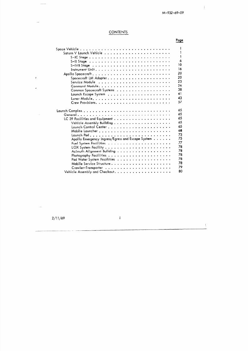
8/8/2019 Apollo 9 Mission Operation Report
http://slidepdf.com/reader/full/apollo-9-mission-operation-report 107/230
Space Vehicle .............................. 1
Saturn V Launch Vehicle ...................... 1
S-IC Stage. .......................... 1
S-II Stage ........................... 6
S-IVB Stage .......................... 10
Instrument Unit. ........................ 16
Apollo Spacecraft. ......................... 20Spacecraft LM Adapter. .................... 20
Service Module ........................ 23
Command Module. ....................... 26
Common Spacecraft Systems .................. 38
Launch Escape System ..................... 41
Lunar Module. ......................... 43
Crew Provisions. ........................ 57
Launch Complex ............................. 65General. .............................. 65
LC 39 Facilities and Equipment ................... 65
Vehicle Assembly Building ................... 65
Launch Control Center ..................... 65
Mobile Launcher ........................ 68
Launch Pad. .......................... 73
Apollo Emergency Ingress/Egress and Escape System ...... 75
Fuel System Facilities ..................... 77
M-932-69-09
Page
S d C l 81

8/8/2019 Apollo 9 Mission Operation Report
http://slidepdf.com/reader/full/apollo-9-mission-operation-report 108/230
Mission Monitoring, Support, and Control ................ 81
General ............................... 81
Vehicle Flight Control Capability. ................. 82Space Vehicle Tracking. .................... 86
Command System ........................ 86
Display and Control System ...................
Contingency Planning and Execution ................“8:
MCC Role in Aborts. ...................... 87
Vehicle Flight Control Parameters. .................
Parameters Monitored by LCC ..................
ii
Parameters Monitored by Booster Systems Group ........ 88
Parameters Monitored by Flight Dynamics Group ........ 88
Parameters Monitored by Spacecraft Systems Group. ...... 88
Parameters Monitored by Life Systems Group .......... 89
Manned Space Flight Network. ...................
NASA Communications Network. ..................iy
Apollo Launch Data System (ALDS) ................. 93
MSFC Support for Launch and Flight Operations. .......... 93
Abbreviations and Acronyms . . . . . . . . . . . . . . . . . . . . . . . 94
M-932-69-09
LIST OF FIGURES

8/8/2019 Apollo 9 Mission Operation Report
http://slidepdf.com/reader/full/apollo-9-mission-operation-report 109/230
Figure
1
2
3
4
5
6
7
8
9
10
11
12
Title
Apollo Saturn V Space Vehicle
S-IC Stage
S-II Stage
S-IVB Stage
APS Functions
APS Control Module
Saturn Instrument Unit
Spacecraft LM Adapter
S LA Panel Jettisoning
Service Module
Command Module
Main Display Console
Page
2
3
7
11
14
15
17
21
22
24
27
31
M-932-69-09
20 LM Physical Characteristics 46

8/8/2019 Apollo 9 Mission Operation Report
http://slidepdf.com/reader/full/apollo-9-mission-operation-report 110/230
21
22
23
24
25
26
27
28
29
30
31
32
33
LM Ascent Stage
LM Descent Stage
LM Communications Links
Apollo Apparel
LM Crewman at Flight Station
LM Crewmen Rest Positions
Launch Complex 39
Vehicle Assembly Building
Mobile Launcher
Holddow n Arms/Tail Service Mast
Mobile Launcher Service Arms
Launch Pad A, LC 39
Launch Structure Exploded View
47
48
55
58
63
63
66
67
69
71
72
73
74
40 MCC Organization 83
M-932-69-09
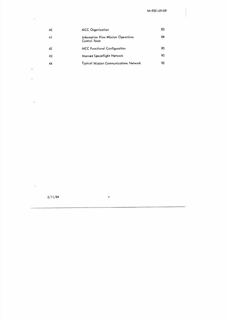
8/8/2019 Apollo 9 Mission Operation Report
http://slidepdf.com/reader/full/apollo-9-mission-operation-report 111/230
41
42
43
44
Information Flow Mission OperationsControl Room
MCC Functional Configuration
Manned Spaceflight Network
Typical Mission Communications Network
84
85
90
92
M-932-69-09
SPACE VEHICLE
The primary flight hardware of the Apollo program consists of a Saturn V Launch Vehicle

8/8/2019 Apollo 9 Mission Operation Report
http://slidepdf.com/reader/full/apollo-9-mission-operation-report 112/230
and an Apollo Spacecraft. Collectively, they are designated the Apollo-Saturn V SpaceVehicle (SV) (Figure 1).
SATURN V LAUNCH VEHICLE
The Saturn V Launch Vehicle (LV) is designed to boost up to 285,000 pounds into a
105 nautical mile earth orbit and to provide for lunar payloads of 100,000 pounds.
The Saturn V LV consists of three propulsive stages (S-IC, S-II, S-IVS), two interstages,
and an Instrument Unit (IU).
S-IC Stage
General
The S-IC stage (Figure 2) is a large cylindrical booster, 138 feet long and 33 feet
in diameter, powered by five liquid propellant F-l rocket engines. These engines
develop a nominal sea level thrust total of approximately 7,650,OOO pounds andhave an operational burn time of 159 seconds. The stage dry weight is approximately
295,300 pounds and the total loaded stage weight is approximately 5,031,500 pounds.
The S-IC stage interfaces structurally and electrically with the S-II stage. It also
interfaces structurally, electrically, and pneumatically with Ground Support Equip-
ment (GSE) through two umbilical service arms, three tail service masts, and certain
electronic systems by antennas. The S-IC stage is instrumented for operational
measurements or signals which are transmitted by its independent telemetry system.
Structure
M-932-69-09
APOLLO-SATURNVSPACEVEHICLE
!UMENT

8/8/2019 Apollo 9 Mission Operation Report
http://slidepdf.com/reader/full/apollo-9-mission-operation-report 113/230
.
--
SYSTEM
T‘ECTIVE COVER
COMMAND MODULE
SERVICE MODULE
r
INTER.’STAGE
INTER-STAGE

8/8/2019 Apollo 9 Mission Operation Report
http://slidepdf.com/reader/full/apollo-9-mission-operation-report 114/230
M-932-69-09
The thrust structure assembly redistributes the applied loads of the five F-l engines
into nearly uniform loading about the periphery of the fuel tank. Also, it provides
support for the five F-l engines, engine accessories, base heat shield, engine
fairings and fins, propellant lines, retrorockets, and environmental control ducts.

8/8/2019 Apollo 9 Mission Operation Report
http://slidepdf.com/reader/full/apollo-9-mission-operation-report 115/230
The lower thrust ring has four holddown points which support the fully loaded
Saturn V Space Vehicle (approximately 6,483,OOO pounds) and also, as necessary,
restrain the vehicle during controlled release.
Propulsion
The F-l engine is a single-start, 1,530,000-pound fixed-thrust, calibrated, bi-propellant engine which uses Liquid Oxygen (LOX) as the oxidizer and Rocket
Propellant-l (RP-1) as the fuel. The thrust chamber is cooled regeneratively by
fuel, and the nozzle extension is cooled by gas generator exhaust gases. Oxidizer
and fuel are supplied to the thrust chamber by a single turbopump powered by a
gas generator which uses the same propellant combination. RP-1 is also used asthe turbopump lubricant and as the working fluid for the engine hydraulic control
system. The four outboard engines are capable of gimbaling and have provisions
for supply and return of RP-1 as the working fluid for a thrust vector control system.
The engine contains a heat exchanger system to condition engine-supplied LOX
and externally supplied he lium for stage propellant tank pressurization. An
instrumentation system monitors engine performance and operation. External
thermal insulation provides an allowable engine environment during flight operation.
The normal in-flight engine cutoff sequence is center engine first, followed by the
four outboard engines. Engine optical-type depletion sensors in either the oxidizer
or fuel tank initiate the engine cutoff sequence. In an emergency, the engine
can be cut off by any of the following methods: Ground Support Equipment (GSE)
Command Cutoff, Emergency Detection System, or Outboard Cutoff System.
M-932-69-09
Gaseous Oxygen (GOX) is used for oxidizer tank pressurization during fligh t. A
portion of the LOX supplied to each engine is diverted into the engine heat
exchangers where it is transformed into GOX and routed back to the tanks. LOX

8/8/2019 Apollo 9 Mission Operation Report
http://slidepdf.com/reader/full/apollo-9-mission-operation-report 116/230
is delivered to the engines through five suction lines which are supplied with flexand sliding joints.
Flight Control System
The S-IC thrust vector control consists of four outboard F-l engines, gimbal blocks
to attach these engines to the thrust ring, engine hydraulic servoactuators (two
per engine), and an engine hydraulic power supply. Engine thrust is transmitted
to the thrust structure through the engine gimbal block. There are two servo-actuator attach points per engine, located 90 degrees from each other, through
which the gimbaling force is applied. The gimbaling of the four outboard engines
changes the direction of thrust and as a result corrects the attitude of the vehicle
to achieve the desired trajectory. Each outboard engine may be gimbaled +5O
within a square pattern at a rate of 5O per second.
Electrical
The electrical power system of the S-IC stage consists of two basic subsystems:
the operational power subsystem and the measurements power subsystem. Onboardpower is supplied by two 28-volt batteries. Battery number 1 is identified as the
operational power system battery. It supplies power to operational loads such as
valve controls, purge and venting systems, pressurization systems, and sequencing
and flight control. Battery number 2 is identified as the measurement power system.
Batteries supply power to their loads through a common m ain power distributor, but
each system is completely isolated from the other. The S-IC stage switch selector
M-932-69-09
Eight retrorockets provide thrust after S-IC burnout to separate it from the S-II
stage. The S-K retrorockets are mounted in pairs external to the thrust structure
in the fairings of the four outboard F-l engines. The firing command originates

8/8/2019 Apollo 9 Mission Operation Report
http://slidepdf.com/reader/full/apollo-9-mission-operation-report 117/230
in the IU and activates redundant firing systems. At retrorocket ignition the for-ward end of the fairing is burned and blown through by the exhausting gases. The
thrust level developed by seven retrorockets (one retrorocket out) is adequate to
separate the S-IC stage a minimum of six feet from the vehicle in less than one
second.
S-II Staae
General
The S-II stage (Figure 3) is a large cylindrical booster, 81.5 feet long and 33 feet
in diameter, powered by five liquid propellant J-2 rocket engines which develop
a nominal vacuum thrust of 230,000 pounds each for a total of 1,150,OOO pounds.
Dry weight of the S-II stage is approximately 84,600 pounds. The stage approxi-
mate loaded gross weight is 1,064,600 pounds. The S-IC/S-II interstage weighs
11,665 pounds. The S-II stage is instrumented for operational and R&D measure-
ments which are transmitted by its independent telemetry system. The S-II stagehas structural and electrical interfaces with the S-IC and S-IV stages, and electric,
pneumatic, and fluid interfaces with GSE through its umbilicals and antennas.
Structure
Major S-II structural components are the forward skirt, the 37,737-cubic foot fuel
tank, the 12,745-cubit foot oxidizer tank (with the common bulkhead), the aft
skirt/thrust structure, and the S-IC/S-II interstage. Aluminum alloy is the major
M-932-69-09
S-II STAGE

8/8/2019 Apollo 9 Mission Operation Report
http://slidepdf.com/reader/full/apollo-9-mission-operation-report 118/230
VEHICLESTATION2519
-
81-l/2FEET
I-SYSTEMS TUNNEL
tFORWARDSKIRT
11-l/2 FEET
I
LH2/LOX COMMONBULKHEAD
Y ’LIQUID OXYGENTANK(12.745.5 CU FT)

8/8/2019 Apollo 9 Mission Operation Report
http://slidepdf.com/reader/full/apollo-9-mission-operation-report 119/230
M-932-69-09
Flight Control System
Each outboard engine is equipped with a separate, independent, closed-loop,
hydraulic control system that includes two servoactuators mounted in perpendicular

8/8/2019 Apollo 9 Mission Operation Report
http://slidepdf.com/reader/full/apollo-9-mission-operation-report 120/230
planes to provide vehicle control in pitch, roll, and yaw. The servoactuators are
capable of deflecting the engine +7 degrees in the pitch and yaw planes (+lO degrees
diagonally) at the rate of 8 degrees per second.
Electrical
The electrical system is comprised of the electrical power and electrical controlsubsystems. The electrical power system provides the S-II stage with the electrical
power source and distribution. The electrical control system interfaces with the
IU to accomplish the mission requirements of the stage. The LVDC in the IU con-
trols in-flight sequencing of stage functions through the stage switch selector.
The stage switch selector outputs are routed through the stage electrical sequence
controller or the separation controller to accomplish the directed operation. These
units are basically a network of low-power transistorized switches that can be con-
trolled individually and, upon command from the switch selector, provide properly
sequenced electrical signals to control the stage functions.
Ordnance
The S-II ordnance systems include the separation, ullage rocket, retrorocket, and
propellant dispersion (flight termination) systems. For S-IC/S-II separation, a
dual-plane separation technique is used wherein the structure between the two
stages is severed at two different planes. The second-plane separation jettisons
the interstage after S-II engine ignition. The S-II/S-IVB separation occurs at a
single plane located near the aft skirt of the S-IVB stage. The S-IVB interstage

8/8/2019 Apollo 9 Mission Operation Report
http://slidepdf.com/reader/full/apollo-9-mission-operation-report 121/230
M-932-69-09
S-IV6 STAGE
FORWARDSKIRT
t10.2 FEET

8/8/2019 Apollo 9 Mission Operation Report
http://slidepdf.com/reader/full/apollo-9-mission-operation-report 122/230
55FE
I-- 21.6 FEET-
FORWARDSKIRT
LH2 TANKI
10,418 I ICUFT I* I
\\2830/
cu Fr
44.c
,
7.0
EET
:ET
M-932-69-09
During engine operation, the oxidizer tank is pressurized by flowing cold helium
(from helium spheres mounted inside the fuel tank) through the heat exchanger in
the oxidizer turbine exhaust duct. The heat exchanger heats the cold helium,
causing it to expand. The fuel tank is pressurized during engine operation by GH2
from the thrust chamber fuel manifold Thrust vector control in the pitch and yaw

8/8/2019 Apollo 9 Mission Operation Report
http://slidepdf.com/reader/full/apollo-9-mission-operation-report 123/230
-
from the thrust chamber fuel manifold. Thrust vector control in the pitch and yaw
planes during burn periods is achieved by gimbaling the entire engine.
The J-2 engine may receive cutoff signals from the following sources; EDS, range
safety systems, “Thrust OK” pressure switches, propellant depletion sensors, and
an IU programmed command (velocity or timed) via the switch selector.
The restart of the J-2 engine is identical to the initial start except for the fill
procedure of the start tank. The start tank is filled with LH2 and GH2 during the
first burn period by bleeding GH2 from the thrust chamber fuel injection manifold
and LH2 from the Augmented Spark Igniter (ASI) fuel line to refill the start tank
for engine restart. (Approximately 50 seconds of mainstage engine operation is
required to recharge the start tank.)
To insure that sufficient energy will be available for spinning the fuel and oxidizer
pump turbines, a waiting period of between approximately 80 minutes to 6 hours
is required. The minimum time is required to build sufficient pressure by warmingthe start tank through natural means and to allow the hot gas turbine exhaust system
to cool. Prolonged heating will cause a loss of energy in the start tank. This loss
occurs when the LH2 and GH2 warm and raise the gas pressure to the relief valve
setting. If this venting continues over a prolonged period the total stored energy
will be depleted. This limits the waiting period prior to a restart attempt to six
hours.
Propellant Systems

8/8/2019 Apollo 9 Mission Operation Report
http://slidepdf.com/reader/full/apollo-9-mission-operation-report 124/230
M-932-69-09
APS FUNCTIONS

8/8/2019 Apollo 9 Mission Operation Report
http://slidepdf.com/reader/full/apollo-9-mission-operation-report 125/230
M-932-69-09
APS CONTROLMODULE

8/8/2019 Apollo 9 Mission Operation Report
http://slidepdf.com/reader/full/apollo-9-mission-operation-report 126/230
OUTER MODULE
HIGH PRESSUREHELIUM SPHERES I
OXIDIZER TANK-7
FUEL TANK150 LB PITCH
ENGINE7
150 LB ROLL ANDYAW ENGINE (2) 1
70 LB ULLAGEENGINE-
M-932-69-09
Ordnance
The S-IVB ordnance systems include the separation, ullage rocket, and PDS systems.
The separation plane for S-II/S-IVB staging is located at the top of the S-II/S-IVB
interstage. At separation four retrorocket motors mounted on the interstage structure
below the separation plane fire to decelerate the S-II stage with the interstage

8/8/2019 Apollo 9 Mission Operation Report
http://slidepdf.com/reader/full/apollo-9-mission-operation-report 127/230
p p g g
attached.
To provide propellant settling and thus ensure stable flow of fuel and oxidizer
during J-2 engine start, the S-IVB stage requires a small acceleration. This
acceleration is provided by two jettisonable ullage rockets for the first burn. TheAPS provides ullage for subsequent burns.
The S-IVB PDS provides for termination of vehicle flight by cutting two parallel
20-foot openings in the fuel tank and a 47-inch diameter hole in the LOX tank.The S-IVB PDS may be safed after the launch escape tower is jettisoned. Following
S-IVB engine cutoff at orbit insertion, the PDS is electrically safed by ground
command.
Instrument Unit
General
The Instrument Unit (IU) (F’g ure 7), is a cylindrical structure 21 .6 feet in diameter
and 3 feet high installed on top of the S-IVB stage. The IU contains the guidance,
navigation, and control equipment for the Launch Vehicle. In addition, it contains
measurements and telemetry, command communications, tracking, and emergency
detection system components along with supporting electrical power and environ-
mental control systems.

8/8/2019 Apollo 9 Mission Operation Report
http://slidepdf.com/reader/full/apollo-9-mission-operation-report 128/230
M-932-69-09
The three-gimbal stabilized platform (ST-124-M3) provides a space-fixedcoordinate reference frame for attitude control and for navigation (acceleration)measurements. Three integrating accelerometers, mounted on the gyro-stabilized
inner gimbal of the platform, measure the three components of velocity resulting
from vehicle propulsion. The accelerometer measurements are sent through the

8/8/2019 Apollo 9 Mission Operation Report
http://slidepdf.com/reader/full/apollo-9-mission-operation-report 129/230
Launch Vehicle Data Adapter (LVDA) to the LVDC. In the LVDC, the acceler-ometer measurements are combined with the computed gravitational acceleration
to obtain velocity and position of the vehicle. During orbital flight, the navi-
gational program continually computes the vehicle position, velocity, and
acceleration. Guidance information stored in the LVDC (e.g., position, velocity)
can be updated through the IU command system by data transmission from ground
stations. The IU command system provides the general capability of changing or
inserting information into the LVDC.
The control subsystem is designed to maintain and control vehicle attitude by
forming the steering commands to be used by the controlling engines of the active
stage. The control system accepts guidance computations from the LVDC/LVDA
Guidance System. These guidance commands, which are actually attitude error
signals, are then combined with measured data from the various control sensors.
The resultant output is’the command signal to the various engine actuators and
APS nozzles. The final computations (analog) are performed within the FCC.The FCC is also the central switching point for command signals. From this point,the signals are routed to their associated active stages and to the appropriate
attitude control devices.
Measurements and Telemetry
The instrumentation within the IU consists o f a measuring subsystem, a telemetry
subsystem and an antenna subsystem. This instrumentation is for the purpose of
M-932-69-09
Saturn Tracking Instrumenta tion
The Saturn V IU carries two C-band radar transponders and an Azusa/GLOTRAC
tracking transponder. A combination of tracking data from different tracking
systems provides the best possible trajectory information and increased reliability

8/8/2019 Apollo 9 Mission Operation Report
http://slidepdf.com/reader/full/apollo-9-mission-operation-report 130/230
through redundant data. The tracking of the Saturn Lau nch Vehicle may be
divided into four phases: powered flight into earth orbit; orbital flight; injection
into mission trajectory; and coast flight after injection. Continuous tracking is
required during powered flight into earth orbit. During orbital flight, tracking is
accomplished by S-band stations of the MSFN and by C-band radar stations.
IU Emergency Detection System Components
The Emergency Detection System (EDS) is one element of several crew safety
systems. There are nine EDS rate gyros installed in the IU. Three gyros monitor
each of the three axes (pitch, roll, and yaw) thus providing triple redundancy.
The control signal processor provides power to and receives inputs f rom the nine
EDS rate gyros. These inputs are processed and sent on to the EDS distributor and
to the flight control computer. The EDS distributor serves as a junction box and
switching device to furnish the spacecraft display panels with emergency signals
if emergency conditions exist. It also contains relay and diode logic for theautomatic abort sequence.
An electronic timer in the IU allows multiple engine shutdowns without automatic
abort after 30 seconds of flight. Inhibiting of automatic abort circuitry is
also provided by the vehicle flight sequencing circuits through the IU switch
selector. This inhibiting is required prior to normal S-IC engine cutoff and other
normal vehicle sequencing. While the automatic abort is inhibited, the flight
crew must initiate a manual abort if an angular-overrate or two engine-out con-

8/8/2019 Apollo 9 Mission Operation Report
http://slidepdf.com/reader/full/apollo-9-mission-operation-report 131/230
M-932-69-09
SPACECRAFT M ADAPTER
A CIRCUMFERENTIALLINEAR SHAPED CHARGE

8/8/2019 Apollo 9 Mission Operation Report
http://slidepdf.com/reader/full/apollo-9-mission-operation-report 132/230
UPPER (FORWARD)21’ JETTISONABLE
PANELS(4 PLACES)
LONGITUDINAL
1 CIRCUMFERENTIAL+
LOWER (AFT)LINEAR SHAPED CHARGE
7’ FIXED PANELSSPRING THRUSTER/HINGE
S LA-SM Seoaration
Fig. 8
The SLA and SM are bolted together through flanges on each of the two structures.
Explosive trains are used to separate the SLA and SM as well as for separating the
four upper jettisonable SLA panels. Redundancy is provided in three areas to
assure separation; redundant initiating signals, redundant detonators and cord
trains, and “sympathetic” detonation of nearby charges.
M-932-69-09
SLA PANEL JET-T-ISONING

8/8/2019 Apollo 9 Mission Operation Report
http://slidepdf.com/reader/full/apollo-9-mission-operation-report 133/230
LOWER HINGE
SPRING THRUSTER AFTER PANEL SPRING THRUSTER BEFORE PANELDEPLOYMENT, AT START OFJETTISON DEPLOYMENT
Fig. 9
SLA LM Seoaration
M-932-69-09
Service Module
General
The Service Module (SM) (F’gure 10) provides the main spacecraft propulsion and
maneuvering capability during a mission. The SM provides most of the spacecraft

8/8/2019 Apollo 9 Mission Operation Report
http://slidepdf.com/reader/full/apollo-9-mission-operation-report 134/230
consumables (oxygen, water, propellant, hydrogen) and supplements environmental,
electrical power, and propulsion requirements of the CM. The SM remains attachedto the CM until it is iettisoned just before CM reentry.
Structure
The basic structural components are forward and aft (upper and lower) bulkheads,
six radial beams, four sector honeycomb panels, four reaction control system honey-comb panels, aft heat shield, and a fairing. The forward and aft bulkheads coverthe top and botton of the SM. Radial beam trusses extending above the forwardbulkhead support and secure the CM. The radial beams are made of solid aluminum
alloy which has been machined and them-milled to thicknesses varying between 2
inches and 0.018 inch. Three of these beams have compression pads and the otherthree have shear-compression pads and tension ties. Explosive charges in the centersections of these tension ties are used to separate the CM from the SM.
An aft heat shield surrounds the service propulsion engine to protect the SM from
the engine’s heat during thrusting. The gap between the CM and the forward
bulkhead of the SM is closed off with a fairing which is composed of eight elec-
trical power system radiators alternated with eight aluminum honeycomb panels.
The sector and reaction control system panels are one inch thick and are made of
aluminum honeycomb core between two aluminum face sheets. The sector panels
are bolted to the radial beams. Radiators used to dissipate heat from the environ-
mental control subsystem are bonded to the sector panels on opposite sides of the
M-932-69-09
SERVICEMODULE

8/8/2019 Apollo 9 Mission Operation Report
http://slidepdf.com/reader/full/apollo-9-mission-operation-report 135/230
SCIMITARANTENNP
-_..FLOODLIGHT
DOCKING
tl ----IGHT
ENVIRONMENTALCONTROL SUBSYSTEMRADIATOR NOZZLE EXTENSION
FUELTANKS y#fL~~~~~M
FORWARD BULKHEAD INSTALL \__-. _”

8/8/2019 Apollo 9 Mission Operation Report
http://slidepdf.com/reader/full/apollo-9-mission-operation-report 136/230
M-932-69-09
SM/CM Separation
Separation of the SM from the CM occurs shortly before reentry. The sequence of
events during separation is controlled automatically by two redundant Service
Module Jettison Controllers (SMJC) Iocated on the forward bulkhead of the SM.Physical separation requires severing of all the connections between the modules

8/8/2019 Apollo 9 Mission Operation Report
http://slidepdf.com/reader/full/apollo-9-mission-operation-report 137/230
Physical separation requires severing of all the connections between the modules,
transfer of electrical control, and firing of the SM RCS to increase the distance between
the CM and SM. A tenth o f a second after e lectrical connections are deadfaced,
the SMJC’s send signals which fire ordnance devices to sever the three tension ties
and the umbilical. The tension ties are straps which hold the CM on three of the
compression pads on the SM. Linear-shaped charges in each tension tie assembly
sever the tension ties to separate the CM from the SM. At the same time, explosive
charges drive guillotines through the wiring and tubing in the umbilical. Simul-taneously with the firing of the ordnance devices, the SMJC’s send signals whichfire the SM RCS. Roll engines are fired for five seconds to alter the SM’s course
from that of the CM, and the translation (thrust) engines are fired continuously
until the propellant is depleted or fuel cell power is expended. These maneuvers
carry the SM well away from the entry path of the CM.
Command Module
General
The Command Module (CM) (Figure 11) serves as the command, control, and
communications center for most of the mission. Supplemented by the SM, it pro-
vides all life support elements for three crewmen in the mission environments and
for their safe return to earth’s surface. It is capable of attitude control about
three axes and some lateral lift translation at high velocities in earth atmosphere.
It also permits LM attachment CM/LM ingress and egress and serves as a buoyant

8/8/2019 Apollo 9 Mission Operation Report
http://slidepdf.com/reader/full/apollo-9-mission-operation-report 138/230

8/8/2019 Apollo 9 Mission Operation Report
http://slidepdf.com/reader/full/apollo-9-mission-operation-report 139/230
M-932-69-09
Crew Compartment
The crew compartment has a habitable volume of 210 cubic feet. Pressurizationand temperature are maintained by
theECS. The crew compartment contains the
controls and displays for operation of the spacecraft, crew couches, and all the
th i t d d b th It t i t h t h fi i d d

8/8/2019 Apollo 9 Mission Operation Report
http://slidepdf.com/reader/full/apollo-9-mission-operation-report 140/230
other equipment needed by the crew. It contains two hatches, five windows, and
a number of equipment bays.
Equipment Bays
The equipment bays contain items needed by the crew for up to 14 days, as well
as much of the electronics and other equipment needed for operation of the space-
craft. The bays are named according to their position with reference to the couches.
The lower equipment bay is the largest and contains most of the guidance and
navigation electronics, as well as the sextant and telescope, the Command Module
Computer (CMC), and a computer keyboard. Most of the telecommunications sub-
system electronics are in this bay, including the five batteries, inverters, and
battery charger of the electrical power subsystem. Stowage areas in the bay con-
tain food supplies, scientific instruments, and other astronaut equipment.
The Ibft-hand equipment bay contains key elements of the ECS. Space is provided
in this bay for stowing the forward hatch when the CM and LM are docked and thetunnel between the modules is open. The left-hand forward equipment bay also
contains ECS equipment, as well a s the water delivery unit and clothing storage.
The right-hand equipment bay contains waste management system controls and
equipment, electrical power equipment, and a variety of electronics, including
sequence controllers and signal conditioners. Food also is stored in a compartment
in this bay The right-hand forward equipment bay is used principally for stowage
M-932-69-09
the locking pressure of the latches. The hatch handle mechanism also operates a
mechanism which opens the access hatch in the BPC. A counterbalance assembly
which consists of two nitrogen bottles and a piston assembly enables the hatch and
BPC hatch to be opened easily. In space, the crew can operate the hatch easily
without the counter balance, and the piston cylinder and nitrogen bottle can bevented after launch. A second nitrogen bottle can be used to open the hatch after

8/8/2019 Apollo 9 Mission Operation Report
http://slidepdf.com/reader/full/apollo-9-mission-operation-report 141/230
landing. The side hatch can readily be opened from the outside. In case somedeformation or other malfunction prevented the latches from engaging, three jack-
screws are provided in the crew’s tool set to hold the door’closed.
The forward (docking) hatch is a combined pressure and ablative hatch mounted at
the top of the docking tunnel. The exterior or upper side of the hatch is covered
with a half-inch of insulation and a layer of aluminum foil. This hatch has a six-point latching arrangement operated by a pump handle similar to that on the side
hatch and can also be opened from the outside. It has a pressure equalization
valve so that the pressure in the tunnel and that in the LM can be equalized before
the hatch is removed. There are also provisions for opening the latches manually
if the handle gear mechanism should fail.
Windows
The CM has five windows: two side (numbers 1 and 5), two rendezvous (numbers
2 and 4), and a hatch window (number 3 or center). The hatch window is over
the center couch. The windows each consist of inner and outer panes. The inner
windows are made of tempered silica glass with quarter-inch thick double panes,
separated by a tenth of an inch. The outer windows are made of amorphous-fused
silicon with a single pane seven tenths of an inch thick. Each pane has an anti-
reflecting coating on the external surface and a blue-red reflective coating on the
inner surface to filter out most infrared and all ultraviolet rays. The outer window

8/8/2019 Apollo 9 Mission Operation Report
http://slidepdf.com/reader/full/apollo-9-mission-operation-report 142/230
M-932-69-09
The LM Pilot couch faces the right-center and right side of the console. Communi-
cations, electrical control, data storage, and fuel cell system components are
located here, as well as service propulsion subsystem propellant management.
Other displays and controls are placed throughout the cabin in the various equipmentbays and on the crew couches. Most of the guidance and navigation equipment is in

8/8/2019 Apollo 9 Mission Operation Report
http://slidepdf.com/reader/full/apollo-9-mission-operation-report 143/230
the lower equipment bay, at the foot of the center couch. This equipment, including
the sextant and telescope, is operated by an astronaut standing and using a simple
restraint system. The non-time-critical controls of the environmental control system
are located in the left-hand equipment bay, while all the controls of the wastemanagement system are on a panel in the right-hand equipment bay. The rotation
and translation controllers used for attitude, thrust vector, and translation maneuvers
are located on the arms of two crew couches. In addition, a rotation controllercan be mounted at the navigation position in the lower equipment bay.
Critical conditions of most spacecraft systems are monitored by a Caution And
Warning System. A malfunction or out-of-tolerance condition results in illumination
of a status light that identifies the abnormality. It also activates the master alarm
circuit, which illuminates two master alarm lights on the Main Display Console andone in the lower equipment bay and sends an alarm tone to the astronauts’ headsets.
The master alarm lights and tone continue until a crewman resets the master alarmcircuit. This can be done before the crewmen deal with the problem indicated.
The Caution And Warning System also contains equipment to sense its own
malfunctions.
Telecommunications
The telecommunications system (Figure 13) provides voice, television, telemetry,
tracking and ranging communications between the spacecraft and earth between

8/8/2019 Apollo 9 Mission Operation Report
http://slidepdf.com/reader/full/apollo-9-mission-operation-report 144/230

8/8/2019 Apollo 9 Mission Operation Report
http://slidepdf.com/reader/full/apollo-9-mission-operation-report 145/230
M-932-69-09
Antennas LOCATION OF ANTENNAS
There are nine antennas (Figure
15) on the CSM, not counting the
rendezvous radar antenna which isan integral part of the rendezvous
TWO SCIMITAR VHFOMNIDIRECTIONAL A
FOUR SBANO OMNlOlRECTlONAL.NTENNAS ANTENNAS ,j
(160 DEGREES APARTI

8/8/2019 Apollo 9 Mission Operation Report
http://slidepdf.com/reader/full/apollo-9-mission-operation-report 146/230
radar transponder. These antennas
can be divided into four groups:
VHF, S-band, recovery, and
beacon. The two VHF antennas
(called scimitars because of their
shape) are omnidirectional and
are mounted 180 degrees apart onthe SM. There are five S-band
antennas, one mounted at the
bottom of the SM and four located
‘STEERABLE S.BAN;HIGH-GAIN ANTENNA
90 degrees apart around the CM. Fig. 15
The S-band high-gain antennas,
used for deep space communications, is composed of four 31-inch diameter
reflectors surrounding an 1 l-inch square reflector. At launch it is folded down
parallel to the SPS engine nozzle so that it fits within the spacecraft LM adapter.After the CSM separates from the SLA the antenna is deployed at a right angle to
the SM center line. The four smaller surface-mounted S-band antennas are used
at near-earth ranges and deep-space backup. The high-gain antenna is deployable
after CSM/SLA separation. It can be steered through a gimbal system and is the
principal antenna for deep-space communications. The four S-band antennas on
the CM are mounted flush with the surface of the CM and are used for S-band
communications during near-earth phases of the mission, as well as for a backup
in deep space The two VHF recovery antennas are located in the forward com

8/8/2019 Apollo 9 Mission Operation Report
http://slidepdf.com/reader/full/apollo-9-mission-operation-report 147/230
M-932-69-09
ELSMAJORCOMPONENT TOWAGE
OROGUE PARACHUTE MORTAR

8/8/2019 Apollo 9 Mission Operation Report
http://slidepdf.com/reader/full/apollo-9-mission-operation-report 148/230
CTlON CONTROLNGINE PROTECTOR
WRTAA 0 RACESI
I I
Fig 16
M -932-69-09
The two VHF recovery antennas are located in the forward compartment with theparachutes. Th ey are deployed automatically eight seconds after the main para-
chutes. One of them is connected to the beacon transmitter which emits a two-
second signal every five seconds to aid recovery forces in locating the CM. The
other is connected to the VHF/AM transmitter and receiver to provide voice
communica tions between the crew and recovery forces.
f

8/8/2019 Apollo 9 Mission Operation Report
http://slidepdf.com/reader/full/apollo-9-mission-operation-report 149/230
Common Spacecraft Systems
Guidance and Control
The Apollo spacecraft is guided and controlled by two interrelated systems
(Figure 17). One is the Guidance, Navigation, and Control System (GNCS).
The other is the Stabilization and Control System (SCS). The two systems pro-
vide rotational, line-of-flight, and rate-of-speed information. They integrate
and interpret this information and convert it into commands for the spacecraftpropulsion systems.
GUIDANCEANDCONTROL UNCTIONALFLOWVEHICLE DYNAYICS
l----------
1
II I
STABILIZATION SERVICENAVIGATION AND CONTROL SUGSYSTEY PROPULSION -SUSSYSTEY SUBSYSTEM i
- SERVO -AMPLIFIER
4 ILccFYll ” -
NGINE
EACTION

8/8/2019 Apollo 9 Mission Operation Report
http://slidepdf.com/reader/full/apollo-9-mission-operation-report 150/230

8/8/2019 Apollo 9 Mission Operation Report
http://slidepdf.com/reader/full/apollo-9-mission-operation-report 151/230

8/8/2019 Apollo 9 Mission Operation Report
http://slidepdf.com/reader/full/apollo-9-mission-operation-report 152/230
M-932-69-09
Assembly
The forward or rocket section of the system is cylindrical and houses three solid-
propellant rocket motors and a ballast compartment topped by a nose cone and
“Q-ball” which measures attitude and flight dynamics of the space vehicle. The500-pound tower is made of titanium tubes attached at the top to a structural skirt
that covers the rocket exhaust nozzles and at the bottom to the CM by means of

8/8/2019 Apollo 9 Mission Operation Report
http://slidepdf.com/reader/full/apollo-9-mission-operation-report 153/230
explosive bolts. A Boost Protective Cover (BPC) is attached to the tower and com-
pletely covers the CM. It has 12 “blowout” ports for the CM reaction control engines,
vents, and an 8-inch window. This cover protects the CM from the rocket exhaust
and also from the heat generated during launch vehicle boost. It remains attached
to the tower and is carried away when the LES is jettisoned. Two canards mounted
near the forward end of the assembly aerodynamically tumble the CM in the pitchplane during an abort so that the heat shield is forward.
LAUNCHESCAPESYSTEMNOSE CONE 6 0 MALL
P!TCH CONTROL MOTOR
TOWER JETTISON MOTOR,
LAUNCH ESCAPE WTOR,

8/8/2019 Apollo 9 Mission Operation Report
http://slidepdf.com/reader/full/apollo-9-mission-operation-report 154/230
M-932-69-09
LUNAR MODULE
S-BAND DOCKING ASCENTSTEERABLE WINDOW STAGEANTENNA
RENDEZVOUSRADAR
OVERHEAD HATCH/~J~K2;
T

8/8/2019 Apollo 9 Mission Operation Report
http://slidepdf.com/reader/full/apollo-9-mission-operation-report 155/230
ANTENNA
S-BAND RCS THRUSTCHAMBERASSEMBLYCLUSTER
IN-FLIGHT
VHF SCIMITA \DFI ANTENNA (2

8/8/2019 Apollo 9 Mission Operation Report
http://slidepdf.com/reader/full/apollo-9-mission-operation-report 156/230
M-932-69-09
LM PHYSICALCHARACTERISTICSTOTAL
WEIGHT (Propellant & Crew) 32,025 LB.
'1 9,336 LB.EIGHT (Less Prop
ASCENT STAGE
WEIGHT (Less Prop) 5,070 LB.

8/8/2019 Apollo 9 Mission Operation Report
http://slidepdf.com/reader/full/apollo-9-mission-operation-report 157/230
TANKED PROPELLANT (APS) 4,137 LB.
TANKED PROPELLANT (RCS) 608 ,LB.
DESCENT STAGE
WEIGHT (Less Prop) 4.260 LB.
TANKED PROPELLANT(DPS) 17.944 LB.

8/8/2019 Apollo 9 Mission Operation Report
http://slidepdf.com/reader/full/apollo-9-mission-operation-report 158/230

8/8/2019 Apollo 9 Mission Operation Report
http://slidepdf.com/reader/full/apollo-9-mission-operation-report 159/230
M-932-69-09
The Descent Stage has four landing gear to absorb landing shock and to support
the Descent Stage which must serve as a launch pad for the Ascent Stage. The
Descent Stage engine nozzle extension is designed to collapse up to 28 inches
and will not have any influence on LM lunar surface stability. Impact attenuation
is achieved by compression of the main struts against crushable aluminum honeycomb.
The landing gear trusses also provide the structural attachment points for securing
the LM to the lower (fixed) portion of the Spacecraft LM Adapter (SLA). A ladder,integral to a primary landing gear start, provides access from and to the lunar surfacefrom the ten-foot high forward hatch platform.

8/8/2019 Apollo 9 Mission Operation Report
http://slidepdf.com/reader/full/apollo-9-mission-operation-report 160/230
The Descent Stage contains the Descent Propulsion System (DPS) as well as electrical
batteries, landing radar, supplements for the Environmental Control System, six
batteries for the Protable Life Support Systems, a storage area for scientific equip-
ment, an erectable S-band antenna, pyrotechnics, and generally, LM components
not required for the lunar ascent phase of the mission.
Guidance, Navigation, and Control System
The Guidance, Navigation, and Control System (GNKS) provides vehicle guidance,
navigation, and control required for a manned lunar landing mission. The GNKS
utilizes a Rendezvous Radar (RR), and a Landing Radar (LR) to aid in navigation.
The major subsystems of the GN&CS system are designated Primary Guidance and
Navigation Subsystem (PGNS), Abort Guidance Subsystem (AGS), and the Control
Electronics Subsystem (CES).
The GNKS has a primary and alternate system path. The primary guidance path
comprises the Primary Guidance and Navigation Subsystem, Control Electronics Sub-
system, Landing Radar, Rendezvous Radar, and the selected propulsion system. Thealternate system path comprises the Abort Guidance Subsystem, Control Electronics
Subsystem, and the selected propulsion system. The term Primary Guidance, Navi-
M-932-69-09
Abort Guidance Subsystem
The Abort Guidance Subsystem (AGS) provides an independent backup fo r the
PGNS. The section is not utilized during aborts unless the PGNS has failed.
The AGS is capable of determining trajectories required for a coelliptic rendezvoussequence to automatically place the vehicle in a safe parking/rendezvous orbit
with the CSM or can display conditions to be acted upon by the astronauts to
accomplish rendezvous. The activated AGS performs LM navigation, guidance,

8/8/2019 Apollo 9 Mission Operation Report
http://slidepdf.com/reader/full/apollo-9-mission-operation-report 161/230
accomplish rendezvous. The activated AGS performs LM navigation, guidance,
and control in conjunction with the Control Electronics Subsystem (CES). The
AGS differs from the PGNS in that its inertial sensors are rigidly mounted with
respect to the vehicle rather than on a stabilized platform. In this mode, the
Abort Sensor Assembly (ASA) measures attitude and acceleration and supplies data
to the Abort Electronics Assembly (AEA) which is a high-speed digital computer.
Control Electronics Subsystem
The Control Electronics Subsystem (CES) controls LM attitude and translation about
and along three axes by processing commands from the PGNS or AGS and routing
on/of f commands to 16 reaction control engines, ascent engine, or descent engine.
Descent engine thrust vector is also controlled by the CES.
Rendezvous Radar
The Rendezvous Radar (RR) tracks the CSM to provide relative line of sight, range
and range rate data for rendezvous and docking. The transponder in the CSM
augments the transmitted energy of the RR thus increasing radar capabilities and
minimizing power requirements. Radar data is automatically entered into the LGC
in the PGNS mode. During AGS operation, data inputs are entered into the Abort

8/8/2019 Apollo 9 Mission Operation Report
http://slidepdf.com/reader/full/apollo-9-mission-operation-report 162/230

8/8/2019 Apollo 9 Mission Operation Report
http://slidepdf.com/reader/full/apollo-9-mission-operation-report 163/230
M -932-69-09
Two Inverters, each capable of supplying full load, convert the dc to ac for
115-volt, 400-hertz supply. Electrical power is distributed by the followingbuses: LM Pilot’s dc bus, Commanders dc bus, and ac buses A&B.
The four Descent Stage silver-zinc oxide batteries are identical and have a 400ampere-hour capacity at 28 volts. Because the batteries do not have a constantvoltage at various states of charge/load levels, “high” and “low” voltage taps
are provided for selection The “low voltage” tap is selected to initiate use of

8/8/2019 Apollo 9 Mission Operation Report
http://slidepdf.com/reader/full/apollo-9-mission-operation-report 164/230
are provided for selection. The low voltage tap is selected to initiate use ofa fully charged battery. Cross-tie circuits in the busses facilitate an even dis-charge of the batteries regardless of distribution combinations. The two silver-
zinc oxide Ascent Stage batteries are identical to each other and have a 296
ampere-hour capacity at 28 volts. The AS batteries are normally connected in
parallel for even discharge. Because of design load characteristics, the ASbatteries do not have and do not require high and low voltage taps.
Nominal voltage for AS and DS batteries is 30.0 volts. Reverse current relays
for battery failure are one of many components designed into the EPS to enhance
EPS reliability. Cooling of the batteries is provided by the Environmental ControlSystem cold rail heat sinks. Availabl e ascent electrical energy is 17.8 kilowatthours at a maximum drain of 50 amps per battery and descent energy is 46.9 kilo-
watt hours at a maximum drain of 25 amps per battery.
E nvi ronmenta I Contro I System
The Environmental Control System (ECS) provides a habitable environment for two
astronauts for a maximum of 48 hours while the LM is separated from the CSM.
Included in this capability is four cabin decompression/re-pressurization cycles.
The ECS also controls the temperature of electrical and electronic equipment,

8/8/2019 Apollo 9 Mission Operation Report
http://slidepdf.com/reader/full/apollo-9-mission-operation-report 165/230

8/8/2019 Apollo 9 Mission Operation Report
http://slidepdf.com/reader/full/apollo-9-mission-operation-report 166/230

8/8/2019 Apollo 9 Mission Operation Report
http://slidepdf.com/reader/full/apollo-9-mission-operation-report 167/230
-
M-932-69-09
Lighting
Interior lighting is designed to enhance crew performa nce by reducing crew fatiguein an environment of interior-exterior glare effects. Exterior lighting includes aradioluminescent docking target, five docking lights, and a high intensity trackinglight. The five docking lights are automatically turned on prior to the first CSMdocking and are turned off after docking. They indicate gross relative attitude ofthe vehicle and are color d iscernable to a distance of 1000 feet. The flashing,high-intensity tracking light on the LM facilitates CSM tracking of the LMIt

8/8/2019 Apollo 9 Mission Operation Report
http://slidepdf.com/reader/full/apollo-9-mission-operation-report 168/230
.-
high intensity, tracking light on the LM facilitates CSM tracking of the LM.Ithas a beam spread of 60 degrees and flashes 60 times per minute.
Crew Provisions
Appare I
The combination of items a crewman wears varies during a mission (Figure 24).There are three basic configurations of dress: unsuited, suited, and extravehicular.A brief description of each item is contained in the latter part of this section.
Unsuited
This mode of dress is worn by crewmen in the CSM under conditions termed“shirt-sleeve environment.” The crewman wears a biomedical harness, aCommunications Carrier, a Constant Wear Garment, Flight Coveralls, andBooties. This unsuited mode is the most comfortable, convenient, andconsequently, the least fatiguing of the modes. When unsuited, the astro-naut relies upon the CSM ECS to maintain the proper cabin environment ofpressure, temperature, and oxygen.
Suited
4 .
FECALCONTAINMENTSYSTEM
CONSTANT
APOLLO APPAREL
URINECOLCECT!CNTRANSFERASSEMBLV

8/8/2019 Apollo 9 Mission Operation Report
http://slidepdf.com/reader/full/apollo-9-mission-operation-report 169/230
PRESSURE GARMENT
ASSEMBLY WITH
EUNSUITED SUITED
EXTRA ’V EHI CUL ARVISORASSEMBLY/OVER
kid RESSURE GAWENT
H-“lk-aSSEMBLY &
INTEGRAL THERMAL
METEOROID GARMENT
3I8Yo-‘p0
EXTRAVEHICULAR-0
M -932-69-09
Extravehicular
In the extravehicular configuration, the Constant Wear Garment is replacedby a Liquid Cooling Garment and four items are added to the PressureGarment Assembly: Extravehicular Visor Assembly, Extmvehicular Gloves,Lunar Overshoes , and a connector cover which fits over umbilical connectionson the front of the suit. The addition of the Portable Life Support System(PLSS) and Oxygen Purge System back-pack completes the configuration

8/8/2019 Apollo 9 Mission Operation Report
http://slidepdf.com/reader/full/apollo-9-mission-operation-report 170/230
(PLSS) and Oxygen Purge System back pack completes the configurationtermed the Extravehicular Mobility Unit (EMU). The EMU protects the astro-naut from radiation, micrometeorite impact, and lunar surface tempera turesranging from +250°F to -25O’F.
I tern Description
Torso Limb Suit Assembly- The Torso Limb Suit is the basic pressure envelopefor the astronaut. It contains connectors for oxygen, water (for the LiquidCooling Garment), communication, biomedical data, and urine transfer.
Pressure Helmet - The Pressure Helmet is basically a polycarbonate plasticshell. It contains a vent manifold and an air-tight feed port for eating,drinking, and purging. The astronaut can turn his head within the fixedhelmet.
Pressure Glove - The Pressure Glove is basically made of nylon tricot dippedin Neoprene . A fingerless glove, inner and outer covers, and a restraintsystem complete the assembly. The Extravehicular Glove is a modified pressureglove with additional layers of thermal and protective material added .
Integrated Thermal Meteoroid Garment- This garment is sewn over the Torso
M -932-69-09
Extravehicular Visor - The Extravehicular Visor consists of two pivoted poly-carbonate visors mounted on a polycarbonate shell. The visors furnish pro-tection against micrometeoroids, solar heat and radiation, and protection ofthe PGA helmet. The outer visor features a vacuum -deposited gold film.
Liquid Cooling Garment - The Liquid Cooling Garment consists of a networkof Tygon tubing interwoven in nylon Spandex material. Water from the PLSScirculates through the tubing to maintain the desired suit tempe rature. Ani li i f b i d f l hiff Th i l k d i

8/8/2019 Apollo 9 Mission Operation Report
http://slidepdf.com/reader/full/apollo-9-mission-operation-report 171/230
inner liner is fabricated from nylon chiffon. The integral socks do not containcooling tubes.
Constant Wea r Garment - The Constant Wea r Garment is an undergarment forthe flight coveralls and the non-EVA spacesuit configuration. It is fabricatedin one piece, encloses the feet, has short sleeves, a waist to neck zipper,and lower torso openings front and rear.
Flight Coverall - The flight covemll is the outer garment for unsuited operation.It is of two-piece, Beta cloth construction with zipper and pockets.
Booties - Booties worn with the flight covemlls are made of Beta cloth, withVelcro hook material bonded to the soles. During weightlessness , the Velcro
hook engages Velcro pile patches attached to the floor to hold the crewmanin place.
Communications Carrier and Biomedical Harness - The Communications Carrieris a polyurethane foam headpiece which positions two independent earphonesand microphones. The Biomedica l Harness carries signal conditioners and con-verters to transmit heart beat and respiration rates of the astronauts . Thewiring of the Biomedica l Harness and Communications Carrier connect to a

8/8/2019 Apollo 9 Mission Operation Report
http://slidepdf.com/reader/full/apollo-9-mission-operation-report 172/230
M -932-69-09
Couches and Restraints
Command/Service Module
The astronaut couches are individually adiustable units made of hollow s teeltubing and covered with a heavy, fireproof, fiberglass cloth. The couchesrest on a head beam and two side-stabilizer beams supported by eight a ttenuatorstrust (two each for the Y and Z axes and four for the X axis) which absorb the’impact of landing. These couches support the crewmen during accelemtion and

8/8/2019 Apollo 9 Mission Operation Report
http://slidepdf.com/reader/full/apollo-9-mission-operation-report 173/230
-
p g pp gdecelemtion, position the crewmen at their duty stations, and provide supportfor translation and rotation hand controls, lights, and other equipment.
The couches can be folded or adjusted into a number of seat positions. The
one used most is the 85-degree position assumed for launch, orbit entry, andlanding. The 170-deg ree (flat-out) position is used primarily for the centercouch, so that crewmen can move into the lower equipment boy. The armrestson either side of the center couch can be folded footward so the astronautsfrom the two outside couches can slide over easily. The hip pan of the centercouch can be disconnected and the couch can be pivoted around the head beamand laid on the aft bulkhead floor of the CM. This provides both room for theastronauts to stand and easier access to the side hatch for extravehicular
activity.
Two armrests are attached to the back pan of the left couch and two armrestsare attached to the right couch. The center couch has no armrests . Thetranslation and rotation controls can be mounted to any of the four armres ts.A support at the end of each armres t rotates 100 degrees to provide propertilt for the controls. The couch seat pan and leg pan are formed of framingand cloth, and the foot pan is all stee l. The foot pan contains a restraintdevice which holds the foot in place.

8/8/2019 Apollo 9 Mission Operation Report
http://slidepdf.com/reader/full/apollo-9-mission-operation-report 174/230

8/8/2019 Apollo 9 Mission Operation Report
http://slidepdf.com/reader/full/apollo-9-mission-operation-report 175/230

8/8/2019 Apollo 9 Mission Operation Report
http://slidepdf.com/reader/full/apollo-9-mission-operation-report 176/230

8/8/2019 Apollo 9 Mission Operation Report
http://slidepdf.com/reader/full/apollo-9-mission-operation-report 177/230

8/8/2019 Apollo 9 Mission Operation Report
http://slidepdf.com/reader/full/apollo-9-mission-operation-report 178/230

8/8/2019 Apollo 9 Mission Operation Report
http://slidepdf.com/reader/full/apollo-9-mission-operation-report 179/230

8/8/2019 Apollo 9 Mission Operation Report
http://slidepdf.com/reader/full/apollo-9-mission-operation-report 180/230

8/8/2019 Apollo 9 Mission Operation Report
http://slidepdf.com/reader/full/apollo-9-mission-operation-report 181/230
M-932-69-09
HOLDDOWNARMSITAILSERVICEMAST
TAIL SERVICEMAST 3 2 TAIL SERVICE

8/8/2019 Apollo 9 Mission Operation Report
http://slidepdf.com/reader/full/apollo-9-mission-operation-report 182/230
-
MAST 3-2-
TAIL SERVICEMAST 3-4 -
HOLDDOWNARM(TYP 4 PLACES:
ENGINE/HOLDDOWN ARM/TAIL SERVICE MAST ORIENTATION
-TAIL SERVICEMAST 1-2
CONTROLLED RELEASE MECHANISMS
VEHICLESTA 113.31
DIE
TAPERED PIN
BRACKET
M-932-69-09
MOBILELAUNCHER ERVICEARMS
S-IC Intertank (preflight). Provides loxfill and drain interfaces. Umbilicalwithdrawal by pneumatically driven com-pound parallel linkage device. Arm may be,reconnected to vehicle from LCC. Retract
time is 8 seconds. Reconnect time is ap-proximately 5 minutes.
S-IC Forward (preflight). Provides pneu-matic, electrical, and air-conditioninginterfaces. Umbilical withdrawal by pneu-matic disconnect in conjunction with pneu-
4 Command Module Access Arm (preflight).Provides access to spacecraft through en-vironmental chamber. Arm may be retrac-ted or extended fro m LCC. Retracted 12"park position until T-4 minutes. Extent
time is 12 seconds from this position.

8/8/2019 Apollo 9 Mission Operation Report
http://slidepdf.com/reader/full/apollo-9-mission-operation-report 183/230
-
45
j pmatically driven block and tackle/lanyarddevice. Secondary mechanical system. Re-tracted at T-20 seconds. Retract time is8 seconds.
S-II Aft (preflight). Provides access tovehicle. Arm retracted prior to liftoffas required.
S-II Intermediate (inflight). ProvidesLH2 and lox transfer, vent line, pneu-matic, instrument cooling, electrical, andair-conditioning interfaces. Umbilicalwithdrawal systems same as S-IVB Forwardwith addition of a pneumatic cylinder ac-tuated lanyard system. This system oper-ates if primary withdrawal system fails.Retract time is 6.4 seconds (max).
S-II Forward (inflight). Provides GH2vent, electrical, and pneumatic inter-faces. Umbilical withdrawal systems sameas S-IVB Forward. Retract time is 7.4seconds (max).
S-IVB Aft (inflight). Provides LH2 andlox transfer, electrical, pneumatic, and

8/8/2019 Apollo 9 Mission Operation Report
http://slidepdf.com/reader/full/apollo-9-mission-operation-report 184/230
M -932-69-09
LAUNCHSTRUCTUREEXPLODEDVIEW

8/8/2019 Apollo 9 Mission Operation Report
http://slidepdf.com/reader/full/apollo-9-mission-operation-report 185/230
/ -8 10
HIGH PRESSURE GASPTCR 2ND FLOOREGRESS SYSTEMPTCR TUNNEL
ECS TUNNELPTCRECS BUILDINGCOOLING TOWERSUBSTATIONFLUSHING AND COOLINGTANK
Fig. 33
The Pad Terminal Connection Room (PTCR) (Figure 33) provides the terminals for com-
munication and data link transmission connections between the ML or MSS and thelaunch area facilities and between the ML or MSS and the LCC. This facility alsoaccommodates the electronic equipment that simulates functions for checkout of thefacilities during the absence of the launcher and vehicle.
The Environmental Control System (ECS) room, located in the pad fill west of the padstructure and north of the PTCR (Figure 33), houses the equipment which furnishestempera ture and/or humidity-controlled air or nitrogen for space vehicle cooling at

8/8/2019 Apollo 9 Mission Operation Report
http://slidepdf.com/reader/full/apollo-9-mission-operation-report 186/230
M -932-69-09
ELEVATORTUBEEGRESS YSTEM

8/8/2019 Apollo 9 Mission Operation Report
http://slidepdf.com/reader/full/apollo-9-mission-operation-report 187/230
Fig. 35
are provided in the room, including an emergency RF link. An underground air ductfrom the vicinity of the blast room to the remote air intake facility permits egress fromthe pad structure to the pad perimeter. Provision is made to decrease air velocity inthe duct to allow personnel movement through the duct.

8/8/2019 Apollo 9 Mission Operation Report
http://slidepdf.com/reader/full/apollo-9-mission-operation-report 188/230

8/8/2019 Apollo 9 Mission Operation Report
http://slidepdf.com/reader/full/apollo-9-mission-operation-report 189/230
The structure contains five work platformswhich provide access to the space vehicle.The outboard sections of the platforms opento accept the vehicle and close around itto provide access to the launch vehicle and
spacecraft. The lower two platforms arevertically adjustable to serve differentparts of the launch vehicle. The upperthree pla tforms are fixed but can be dis-connected from the tower and relocated asa unit to serve different vehicle config
M-932-69-09
MOBILE SERVICESTRUCTURE

8/8/2019 Apollo 9 Mission Operation Report
http://slidepdf.com/reader/full/apollo-9-mission-operation-report 190/230
a unit to serve different vehicle config-urations. The second and third platformsfrom the top are enclosed and provide
environmental control for the spocecmft.
The MSS is equipped with the followingsystems: air conditioning, electricalpower, various communication networks,fire protection, compressed air, nitrogenpressurization, hydraulic pressure,potable water, and spacecraft fueling.
Crawler-Transporter
The C/‘l (Figure 38) is used to transportthe ML, including the space vehicle, andthe MSS to and from the launch pad. TheC,/? is capable of lifting, transporting,and lowering the ML or the MSS, as
Fig. 37
CRAWLERTRANSPORTER

8/8/2019 Apollo 9 Mission Operation Report
http://slidepdf.com/reader/full/apollo-9-mission-operation-report 191/230

8/8/2019 Apollo 9 Mission Operation Report
http://slidepdf.com/reader/full/apollo-9-mission-operation-report 192/230
M-932-69-09
-
launch vehicle systems real-time support to KSC and MCC for pre-flight,launch, and flight opemtions.
A block diagram of the basic flight control interfaces is shown in Figure 39.
BASICTELEMETRY, COMMAND, ANDCOMMUNICATION NTERFACESFORFLIGHTCONTROL

8/8/2019 Apollo 9 Mission Operation Report
http://slidepdf.com/reader/full/apollo-9-mission-operation-report 193/230
Fig. 39
VEHICLE FLIGHT CONTROL CAPABILITY

8/8/2019 Apollo 9 Mission Operation Report
http://slidepdf.com/reader/full/apollo-9-mission-operation-report 194/230

8/8/2019 Apollo 9 Mission Operation Report
http://slidepdf.com/reader/full/apollo-9-mission-operation-report 195/230

8/8/2019 Apollo 9 Mission Operation Report
http://slidepdf.com/reader/full/apollo-9-mission-operation-report 196/230
M-932-69-09
Space Vehicle Trackina
From lift-off of the launch vehicle to insertion into orbit, accurate position data arerequired to allow the Impact Predictor (IP) to function effectively as a Range Safetydevice, and the RTCC to compute a trajectory and an orbit. These computations are
required by the flight controllers to evaluate the trajectory, the orbit, and/or anyabnormal situations to ensure safe recovery of the astronauts. The launch trackingdata are transmitted from the AFETR site to the IP and thence to the RTCC via high-speed data communications circuits. The IP also generates spacecraft inertial positionsand inertial rates of motion in real-time.

8/8/2019 Apollo 9 Mission Operation Report
http://slidepdf.com/reader/full/apollo-9-mission-operation-report 197/230
During boost the trajectory is calculated and displayed on consoles and plotboards inthe MOCR and SSR’s. Also displayed are telemetry data concerning status of launch
vehicle and spacecraft systems. If the space vehicle deviates excessively from thenominal flight path, or if any critical vehicle condition exceeds tolerance limits, orif the safety of the astronauts or range personnel is endangered, a decision is made toabort the mission.
During the orbit phase of a mission, all stations that are actively tracking the space-craft will transmit the tracking data through GSFC to the RTCC by teletype. If athrusting maneuver is performed by the spacecraft, high-speed tracking data is also
transmitted.
Command System
The Apollo ground command systems have been designed to work closely with thetelemetry and trajectory systems to provide flight controllers with a method of “closed-I oop” command. The astronauts and flight controllers act as links in this operation.
M-932-69-09
Command loads are generated by the real-time computer complex on request of flightcontrollers. Command loads are based on the latest available telemetry and/or tra-jectory data. Flight controllers typically required to generate a command load includethe Booster Systems Engineer (BSE), the Flight Dynamics Officer (FDO), the GuidanceOfficer (GuIDO), and the Retrofire Officer (RETRO).
Disolav and Control System
The MCC is equipped with facilities which provide for the input of data from theMSFN and KSC over a combination of high-speed data, low-speed data, wide-banddata, teletype, and television channels. These data are computer processed for dis-
l h fli h ll

8/8/2019 Apollo 9 Mission Operation Report
http://slidepdf.com/reader/full/apollo-9-mission-operation-report 198/230
play to the flight controllers.
Several methods of displaying data are used including television (projection TV, groupdisplays, closed circuit TV, and TV monitors), console digital readouts, and eventlights. The display and control system interfaces with the RTCC and includes computerrequest, encoder multiplexer, plotting display, slide file, digital-to-TV converter,and telemetry event driver equipments.
-
A control system is provided for flight controllers to exercise their respective functionsfor mission control and technical management. This system is comprised of different
groups of consoles with television monitors,request keyboards, communications equip-
ment , and assorted modules added as required to provide each operational position inthe MOCR with the control and display capabilities required for the particular mission.
CONTINGENCY PLANNING AND EXECUTION
Planning for a mission begins with the receipt of mission requirements and objectives.The planning activity results in specific plans for pre-launch and launch operations,
M-932-69-09
VEHICLE FLIGHT CONTROL PARAMETERS
In order to perform flight control monitoring functions, essential data must be collected,transmitted , processed, displayed, and evaluated to determine the space vehicle’scapability to start or continue the mission.
Parameters Monitored by LCC
The launch vehicle checkout and pre-launch operations monitored by the Launch ControlCenter (LCC) determine the state of readiness of the launch vehicle, ground support,telemetry, range safety, and other operational support systems. During the final count-d h d d f i d i hi l d

8/8/2019 Apollo 9 Mission Operation Report
http://slidepdf.com/reader/full/apollo-9-mission-operation-report 199/230
down, hundreds of parameters are monitored to ascertain vehicle, system, and componentperformance capabilities. Among these parameters are the “redlines.” The redline values
must be within the predetermined limits or the countdown will be halted. In additionto the redlines, there are a number of operational support elements such as ALDS, rangeinstrumentation, ground tracking and telemetry stations, and ground support facilitieswhich must be operational at specified times in the countdown.
Parameters Monitored by Booster Systems Group
The Booster Systems Group (BSG) monitors launch vehicle systems (S-IC, S-II, S-IVB,
and IU) and advises the flight director and flight crew of any system anomalies. It isresponsible for confirming in-flight power, stage ignition, holddown re lease, allengines go, engine cutoffs, etc. BSG also monitors attitude control, stage separations,and digital commanding of LV systems.
Parameters Monitored by Flight Dynamics Group
The Flight Dynamics Group monitors and evaluates the powered flight trajectory and
M-932-69-09
Parameters Monitored by Spacecraft Systems Group
The Spacecraft Systems Group monitors and evaluates the performance of spacecraftelectrical, optical, mechanical, and life support systems; maintains and analyzesconsumables status; prepares the mission log; coordinates telemetry playback; deter-
mines spacecraft weight and center of gravity; and executes digital commanding ofspacecraft systems.
The MOCR positions of this group include the Command and Service Module Electrical,Environmental, and Communications Engineer (CSM EECOM), the CSM Guidance,Navigation, and Control Engineer (CSM GNC), the Lunar Module Electrical, Environ-

8/8/2019 Apollo 9 Mission Operation Report
http://slidepdf.com/reader/full/apollo-9-mission-operation-report 200/230
mental, and Communications Engineer (LM EECOM), and the LM Guidance, Navigation,and Control Engineer (LM GNC). These positions are backed up with detailed support
from the Vehicle Systems SSR.
Parameters Monitored by Life Systems Group
The Life Systems Group is responsible for the well-being of the flight crew. The groupis headed by the Flight Surgeon in the MOCR. Aeromedical and environmental controlspecialists in the Life Systems SSR provide detailed support to the Flight Surgeon. The
L group monitors the flight crew health status and environmental/biomedical parameters.
MANNED SPACE FLIGHT NETWORK
The Manned Space Flight Network (MSFN) (F gure 43) is a global network of groundstations, ships, and aircraft designed to support manned and unmanned space flights.The network provides tmcking, telemetry, voice and teletype communications, command,recording, and television capabilities. The network is specifically configured to meetthe requirements of each mission

8/8/2019 Apollo 9 Mission Operation Report
http://slidepdf.com/reader/full/apollo-9-mission-operation-report 201/230
Cd4.v.cU. 40 T.
M-932-69-09 -

8/8/2019 Apollo 9 Mission Operation Report
http://slidepdf.com/reader/full/apollo-9-mission-operation-report 202/230
ANG ANT
M-932-69-09
opera te as integral stations of the MSFN, meeting target acquisition, tracking, telem-etry, communications, and command and control requirements. The reentry ships haveno telemetry computer, command control system, mission control center, or satellitecommunications terminal. The DOD operates the ships in support of NASA/DODmissions with an Apollo priority. The Military Sea Transport Service provides the
maritime crew and the WTR provides the instrumentation crews by contract. The WTRalso has the operational management responsibility for the ships. The ships may con-tribute to the recovery phase as necessary for contingency landings.
Eight modified C-135 aircraft supplement the ground stations and instrumentation shipsas highly mobile “gap fillers.” The ARIA support other space and missile projec ts whennot engaged in their primary mission of Apollo support The ARIA provide two-way

8/8/2019 Apollo 9 Mission Operation Report
http://slidepdf.com/reader/full/apollo-9-mission-operation-report 203/230
not engaged in their primary mission of Apollo support. The ARIA provide two-wayrelay of; voice communications between the spacecraft and surface stations; reception,
recording, and retransmission of telemetry signals from the spacecraft to the ground(postpass). The aircraft are used: shortly be fore, during, and shortly after injectionburn; from initial communications blackout to final landing; for coverage of a selectedabort area in the event of a “no-go” decision after injection or for any irregular reentry.The ARIA have an endurance of about 10 hours and a cruise airspeed ofabout 450 knots.
NASA COMMUNICATIONS NETWORK
The NASA Communications (NASCOM) network (Figure 44) is a point-to-pointcommunications system connecting the MSFN stations to the MCC. NASCOM ismanaged by the Goddard Space Flight Center, where the primary communicationsswitching center is located. Three smaller NASCOM switching centers are locatedat London, Honolulu, and Canberra. Patrick AFB, Florida and Wheeler AFB, Hawaiiserve as switching centers for the DOD eas tern and western test ranges, respectively.The MSFN stations throughout the world are interconnected by landline, underseacable, radio , and communications satellite circuits. These circuits carry teletype,
i d d i l i f h i i
M-932-69-09
TYPICAL MISSION COMMUNICATIONSNETWORK

8/8/2019 Apollo 9 Mission Operation Report
http://slidepdf.com/reader/full/apollo-9-mission-operation-report 204/230
ACNACSW
ETGAOCC
:Ink
ASCENSION Is. (NASA STATION)CANBERRA SWITCHING STA.ANTIGUA ISLANDAFETR SITE ANTIGUA ISLANDAIRCRAFT OPERATIONS CONTROL CENTER
HSK HONEYSUCKLECR. AUST.HTV USNS HUNTSVILLELLDN LONDONSWITCHINGCENTERLROB MADRID, SPAIN SWITCHING CENTERMAD MADRID, SPAIN
M-932-69-09
APOLLO LAUNCH DATA SYSTEM (ALDS)
The Apollo Launch Data System (ALDS) between KSC and MSC is controlled by MSCand is not routed through GS FC. The ALDS consists of wide-band telemetry, voicecoordination circuits, and a high-speed circuit for the Countdown and Status Trans-mission System (CASTS). In addition, other circuits are provided for launch coordination,tracking data, simulations, public information, television, and recovery.
MSFC SUPPORT FOR LAUNCH AND FLIGHT OPERATIONS
The Marshall Space Flight Center (MSFC), bymeans of the Launch Information ExchangeFacility (LIEF) and the Huntsville Operations Support Center (HOSC), provides real-time

8/8/2019 Apollo 9 Mission Operation Report
http://slidepdf.com/reader/full/apollo-9-mission-operation-report 205/230
support of launch vehicle pre-launch, launch, and flight operations. MSFC also providessupport, via LIEF, for post-flight data delivery and evaluation.
In-depth real-time support is provided for pre-launch, launch, and flight operationsfrom HOSC consoles manned by engineers who perform detailed system data monitoringand analysis.
Pre-launch flight wind monitoring analysis and trajectory simulations are jointly per-formed by MSFC and MSC personnel located at MSFC during the terminal countdown.Beginning at T-24 hours, actual wind data is transmitted periodically from KSC to theHOSC. These measurements are used by the MSFC/MSC wind monitoring team invehicle flight digital simulations to verify the capability of the vehicle with thesewinds. In the event of marginal wind conditions, contingency data are provided MSFCin real-time via the Central Instrumentation Facility (CIF). DATA-CORE and trajectorysimulations are performed on-line to expedite reporting to KSC.
During the pre-launch period, primary support is directed to KSC. At lift-off primaryt t f f KSC t th MCC Th HOSC gi i g l id
M-932-69-09
.-
ABBREVIATIONS AND ACRONYMS
acAEA
AFBAFETRAGSALDSAMAOTAPS
Alternating CurrentAbort Electronics AssemblyAir Force BaseAir Force Eastern Test RangeAbort Guidance SubsystemApollo Launch Data SystemAmplitude ModulationAlignment Optical TelescopeAuxiliary Propulsion System (S-IVB)

8/8/2019 Apollo 9 Mission Operation Report
http://slidepdf.com/reader/full/apollo-9-mission-operation-report 206/230
APS
ARIAARSASASASIBPCBSECASTS
CCATSccsCDPCESCIFCMCOAScs
Ascent Propulsion System (LM)Apollo Range Instrumentation AircraftAtmosphere Revitalization SubsystemApollo SaturnAscent Stage (LM)Augmented Spark IgniterBoost Protective CoverBoost Systems EngineerCountdown and Status Transmission SystemCommunications, Command, and Telemetry SystemCommand Communications SystemCommand Data Processor (MSFN Site)Control Electronics SubsystemCentral Instrumentation FacilityCommand ModuleCrewman Optical Alignment SightCommunications System
M-932-69-09
ECSEDSEDSELS
EMSEMUEPSETREVEVAFCC
Environmental Control SystemEmergency Detection SystemExplosive Devices System (LM)Earth Landing System
Entry Monitor SystemExtravehicular Mobility UnitElectrical Power SystemEastern Test RangeExtravehicularExtravehicular ActivityFlight Control Computer (IU, analog)

8/8/2019 Apollo 9 Mission Operation Report
http://slidepdf.com/reader/full/apollo-9-mission-operation-report 207/230
FDA1
FDO
9GDC
GH2
GN2G NCSGN&CSGOX
GSEGUIDOGSFC
H2HFHOSCHTSKG
g p ( , g)Flight Director Attitude Indicator
Flight Dynamics OfficerGravity force at sea level (1 g)Gyro Display CouplerGaseous HydrogenGaseous NitrogenGuidance, Navigation, ‘and Control SystemGuidance, Navigation, and Control System (LM)Gaseous Oxygen
Ground Support EquipmentGuidance OfficerGoddard Space Flight CenterHydrogenHigh FrequencyHuntsville Operations Support CenterHeat Transport Subsystem (LM)In-flight Coveral I Garment
M-932-69-09
LIEFLM
LN2
LOX, LO2LRLVLVDALVDCMCCMILAMLMMH
Launch Information Exchange FacilityLumar ModuleLiquid NitrogenLiquid OxygenLanding RadarLaunch VehicleLaunch Vehicle Data AdapterLaunch Vehicle Digital ComputerMission Control CenterMerritt Island Launch AreaMobile LauncherM th l H d i

8/8/2019 Apollo 9 Mission Operation Report
http://slidepdf.com/reader/full/apollo-9-mission-operation-report 208/230
MMHMOCMOCRMSCMS FCMSFNMSSNASCOM
N2H4
N, 04NPSH02
OMROPSOSCPCSOSRPCMTEA
Monomethyl HydrazineMission Operations ComputerMission Operations Control RoomManned Spacecraft CenterMarshall Space Flight CenterManned Space Flight NetworkMobile Service StructureNASA Communications NetworkHydrazineNitrogen TetroxideNet Positive Suction HeadOxygenOperations Management RoomOxygen Purge SystemOxygen Supply and Cabin Pressure Control SubsystemOperations Support RoomPulse-Code-Modulation and Timing Electronics Assembly
M-932-69-09
SCscsSCEASECS
SLASMSPSSSRsvTCATCS
SpacecraftStabi I ization and Control SystemSignal Conditioning Electronics AssemblySequential Events Control SystemSpacecraft LM AdapterService ModuleService Propulsion SystemStaff Support RoomSpace VehicleThrust Chamber AssemblyThermal Conditioning System

8/8/2019 Apollo 9 Mission Operation Report
http://slidepdf.com/reader/full/apollo-9-mission-operation-report 209/230
TSMTVUDMHUSBUHFVABVHFWMSWSMRWTR
Tail Service MastTelevisionUnsymmetrical DimethylhydrazineUnified S-bandUI tra-High FrequencyVehicle Assembly BuildingVery High FrequencyWater Management Subsystem (LM)White Sands Missile RangeWestern Test Range
MEMORANDUM
Post LaunchMission Opemtion ReportNo. M-932-69-09
6 May 1969
To: A/Administmtor
From: MA/Apollo Program Director
.T Subject: Apollo 9 Mission &S-504) Post Launch Report #l
.The Apollo 9 mission was successfully launched from the Kennedy Space Center onMonday, 3 March 1969 and was completed as planned, with recovery of the spacecraft

8/8/2019 Apollo 9 Mission Operation Report
http://slidepdf.com/reader/full/apollo-9-mission-operation-report 210/230
and crew in the Atlantic recovery area on Thursday, 13 March 1969 . Initial evaluation
of the flight, based upon quick-look data and crew debriefing, indicates that all missionobjectives were attained. Further detailed analysis of all data is continuing and appro-priate refined results of the mission will be reported in Manned Space Flight Centertechnical reports.
Based on the mission pe rformance as described in this report, I am recommending thatthe Apollo 9 mission be adjudged as having achieved agency preset primary objectivesand be considered a success.
---Giiimt. Gdneml, USAF
Apollo Program Director
APPROVAL:
Report No . M-932-69-09
-

8/8/2019 Apollo 9 Mission Operation Report
http://slidepdf.com/reader/full/apollo-9-mission-operation-report 211/230
M-932-69-09
GENERAL
The Apollo 9 (AS-504) mission was the first manned flight involving the Lunar Module.The crew were James A. McDivitt, Commande r; David R. Scott, Command ModulePilot; and Russell L. Schweicka rt, Lunar Module Pilot. Launch had been initially
scheduled for 28 February 1969, but was postponed for three days because all threecrewmen had virus respiratory infections. The countdown was accomplished withoutany unscheduled holds and the AS-504 Space Vehicle was successfully launched fromLaunch Complex 39 at Kennedy Space Center, Florida, on Monday, 3 March 1969.Recovery of the flight crew and Command Module was successfully accomplished on13 March 1969, for a flight duration of 241 hours 53 seconds.
Initial review of test data indicates that overall performance of the launch vehicle

8/8/2019 Apollo 9 Mission Operation Report
http://slidepdf.com/reader/full/apollo-9-mission-operation-report 212/230
Initial review of test data indicates that overall performance of the launch vehicle,spacecraft, and flight crew together with ground support and control facilities andpersonnel was satisfactory, and that all primary mission objectives were accomplished.
M-932-69-09
.,_
NASA OMSF PRIMARY MISSION OBJECTIVES
FOR APOLLO 9
PRIMARY OBJECTIVES
. Demonstrate crew/space vehicle/mission support facilities performance during
a manned Saturn V mission with CSM and LM.
. Demonstrate LM/crew performance.
. Demonstrate performance of nominal and selected backup Lunar OrbitRendezvous (LOR) mission activities, including:

8/8/2019 Apollo 9 Mission Operation Report
http://slidepdf.com/reader/full/apollo-9-mission-operation-report 213/230
Transposition, docking, LM withdrawal
Intervehicular crew transferExtravehicular capabilitySPS and DPS burnsLM active rendezvous and docking
CSM/LM consumables assessment.
i
@oGe E. Miel lerLt. General, -USAFApollo Program Director
,&sociate Administrator forManned Space Flight
Date: j 4 Fgg bq Date:
M-932-69-09
COUNTDOWN
The terminal countdown for Apollo 9 began at T-28 hours at 10:00 p.m. EST, 1 March1969. The only holds encountered were two planned holds: one at T-16 hours for3 hours, and one at T-9 hours for 6 hours. The count was resumed for the last time at2:00 a.m. EST, 3 March 1969, and proceeded to launch at 11:00:00 a.m. EST.
. FLIGHT SUMMARY
The Apollo 9 mission was launched from Kennedy Space Center, Florida, at 11:OO:OO. a.m. EST, 3 March 1969. All launch vehicle stages performed sa tisfactorily, but
burned slightly longer than planned, inserting the S-IVB/spacecraft combination intoa nominal orbit of 102.3 by 103.9 nautical miles (NM).

8/8/2019 Apollo 9 Mission Operation Report
http://slidepdf.com/reader/full/apollo-9-mission-operation-report 214/230
After post-insertion checkout was completed, the Command/Service Module (CSM)was separated from the S-IVB, transposed, and docked with the Lunar Module (LM).The docked spacecraft was separated from the S-IVB at 4:08:05 GET (Ground ElapsedTime). After separation, two unmanned S-IVB burns were performed to place the S-IVB/Instrument Unit on an earth-escape trajectory. After the third burn, the planned pro-pellant dumps could not be performed.
After spacecraft separation from the launch vehicle, four Service Propulsion System
(SPS) firings were made with the CSM/LM docked.
At approximately 43.5 hours GET, the Lunar Module Pilot (LMP) and the Commander(CDR) transferred to the LM. The first manned firing of the LM Descent PropulsionSystem (DPS) was initiated about 6 hours later. The two crewmen then returned to theCommand Module (CM) for the fifth SPS firing.
At approximately 70 hours GET the LMP and CDR again transferred to the LM for the
M-932-69-09
The sixth SPS firing, to lower apogee, was delayed because the +X translation toprecede the maneuver was not programmed properly. However, the maneuver wasrescheduled and successfully completed in the next revolution.
During the last three days, a seventh SPS firing was made to raise the apogee, andthe SO65 Multispectral Photography Experiment and landmark tracking were accomplished.
Unfavorable weather in the planned landing area caused the deorbit maneuver (SPS 8)to be delayed for one revolution. This decision was made the day before splashdownand recovery forces were redeployed. Final parachute descent and splashdown werewithin sight of the prime recovery ship in the Atlantic Ocean. Splashdown was nearthe target point of 23 degrees 15 minutes north latitude, 68 degrees west longitude,as determined from the onboard computer solution. The crew were safely aboard the

8/8/2019 Apollo 9 Mission Operation Report
http://slidepdf.com/reader/full/apollo-9-mission-operation-report 215/230
p yprime recovery ship, USS Guadalcanal, within 1 hour of splashdown.
Table 1 presents a summary of mission events.
TABLE 1
SUMMARY OF MISSION EVENTS
EVENT
First Motion
Maximum Dynamic Pressure
TIME (GET)HR: MIN: SEC
PLANNED* ACTUAL
oo:oo:oo oo:oo:oo
0o:o 1:2 1 0O:O 1:26
Jettison Launch Escape Tower
S-II Engine Cutoff Command
S-II/S-IVB Separation
S-IVB Engine Ignition
S-IVB Engine Cutoff
Parking Orbit Insertion
Separation and Docking Maneuver Initiation
00:03: 16
00:08:5 1
00:08:52
00:08:55
00: 10:49
00: 10:59
02:33:49
M-932-69-09
00:03: 18
00:08:56
00:08:57
00:09:01
00: 11:05
00:11:15
02:41:16

8/8/2019 Apollo 9 Mission Operation Report
http://slidepdf.com/reader/full/apollo-9-mission-operation-report 216/230
Spacecraft Docking
-
Spacecraft Final Separation
S-IVB Restart Preparation
S-IVB Reignition (2nd Burn)
S-IVB Second Cutoff Signal
S-IVB Restart Preparations
SPS Burn 1
S IVB R i iti (3 d B )
03:05:00kvrox)
04:08:57
04:36: 12
04:45:50
04:46:52
05:59:35
06:O 1:40
06 07 13
03:01:59i
04:08:06
04:36: 17
04:45:56
04:46:58
05:59:4 1
05:59:01
06 07 19
M-932-69-09
SPS Burn 4 28:28:00
Docked DPS Burn 49:42:00
SPS Burn 5 54:25: 19
Undocking 92:39:00
CSM/LM Separation 93:07:40
DPS Phasing 93:51:34
DPS Insertion 95:43:22
28:24:41
49:4 1:35
54:26: 12
92:39:36
93:02:54
93:47:35
95:39:08

8/8/2019 Apollo 9 Mission Operation Report
http://slidepdf.com/reader/full/apollo-9-mission-operation-report 217/230
._.
Concentric Sequence Initiation - LM RCS Burn 96:2 1:OO
Constant Delta Height - APS Burn 97:05:27
Terminal Phase Initiation 98:00: 10
CSM/LM Dot ki ng 99: 13:oo
b%vox)
APS Burn to Propellant Depletion 10 1:58:00
SPS Burn 6 12 1:58:48
SPS Burn 7 169:47:54
96:16:07
96~58~15
97:57:59
99:02:26
101:53:15
123:25:07
169: 39:00
M-932-69-09
MISSION PERFORMANCE
The significant portions of the Apollo 9 mission are discussed herein. Space vehiclesystems and mission support performance are covered in succeeding sections.
TRAJECTORY
The CSM/LM/IU/S-IVB combination was inserted into earth orbit at 00:11:15 GET aftera normal launch phase. The resulting orbital elements and maneuver parameters aregiven in Table II for all engine firings.
Four SPS maneuvers were performed prior to the first docked DPS firing. Each of thefirst three SPS maneuvers was made without requiring a +X translation to settle propel-

8/8/2019 Apollo 9 Mission Operation Report
http://slidepdf.com/reader/full/apollo-9-mission-operation-report 218/230
lants. The fourth SPS maneuver was preceded by an 18-second +X translation madewith the Service Module Reaction Control System (SM RCS).
The fifth docked S’PS maneuver resulted in the perigee being approximately 5 NM lessthan planned causing the rendezvous to be initiated 4 minutes earlier. Small cutofferrors of this magnitude were expected, and real-time trajectory planning for bothrendezvous and deorbit was conducted to accommodate minor adjustments in theinitiation times and velocity increments. Out-of-plane components were added duringthe flight to certain preplanned maneuvers to provide substantial reduction in space-
craft weight without significantly changing the orbital parameters for subsequentmaneuvers.
The trajecto ry aspects of the rendezvous exercise will be discussed in the rendezvoussection.
After the Ascent Stage jettison, a separation maneuver of 3 feet per second (fps) wasf d b h SM RCS Th APS i th fi d t ll t d l ti
TABLE II SUMMARYOFMANEUVERS
T-
First Service Pro pulsion
Second Service Propulsion 111.3 111.2 110.3 849.6 850.6 850.5
Third Service Propulsion 280.0 281.9 279.9 t548.2 2570.7 2567.9
Fourth Service Prop ulsion 28.1 28.4 27.9 299.4 300.9 300.5
First Descent Propulsion 367.0 370.6 372.0 1734.0 1744.0 1737.5
BURN TIME (SECONDS)
‘PrelounctPLANNEC
:eol Time‘LANNED
Prelaunct‘LANNEC
Real TimePLANNECTUAL ACTUAL
5.0 4.96 5.2 36.8 36.8 36.6
T OV (FEET PER SECOND)
‘PrelaunchPLANNED
Real TimePLANNEI ACTUAL
125.2 128.2 127.6X X X
108.7 110.2 111.3
190.2 189.8 192.5X X X
109. I 107.7 110.7
268.2 270.3 274.9X X X
111.3 109.4 112.6
268.7 273.8 275.0X X X
111.4 109.3 112.4
267.6 269.9 274.6X X X
T RESULTANT ORBIT

8/8/2019 Apollo 9 Mission Operation Report
http://slidepdf.com/reader/full/apollo-9-mission-operation-report 219/230
First Descent Propulsion
Fifth Service Pro pulsion 41.5 43.2 43.3 552.3 575.4 572.5
Ascent Propulsion Firingto Depletion
Sixth Service Propulsion
Seventh Service Pro pulsion 9.9 25.0 24.9 252.8 653.3 650.1
241 .aX
-15.1Eighth Service Propulsion 11.7 11.6 11.7 323.3 325.0 322.7
NOTES: * Prelaunch planned refers to Apollo 9 Spacecraft Operational Tmjectory, Revision 2, 20 February 1969.** APS burn to depletion planned for unattainab le apogee value to insure propellant depletion cutoff.
389.0** 444.9** 362.4 5074.9** 7427.5** 5373.4
2.4 1.33 I .40 62.7 38.8 33.7
111.8 109.1 112.1
130.2 129.8 131 .oX X X
129.7 129.8 125.9
4673.3 6932.3 3760.9X x X
128.9** 125.9 126.6
127.9 120.2 123.1X X X
94.6 104.8 108.5
238.7 250.4 253.2X X x
93.9 97.9 100.7
238.5X
---
240.0
-:7
M -932-69-09
EXTRAVEHICULAR ACTIVITY
Extravehicular activity (EVA), pl anned for the third day, was reduced from 2 hours15 minutes to about 1 hour of depressurized LM activity. This change was made be-cause the LMP experienced a minor in-flight illness during the first two days of themission.
Preparation for EVA began at approximately 71 hours GET. The CDR and the LMP werein the LM and the CMP in the CM. At approximately 73 hours GET, after donning thePortable Life Support System (PLSS) and the Oxygen Purge System (OPS), the LMPegressed through the forward hatch and moved to the external foot restraints on theplatform. During this time the CM was depressurized and the side hatch was opened.Thermal sample retrieval was photographically recorded with the sequence cameras.The LMP used the handrails to evaluate body control and transfer techniques Ingress

8/8/2019 Apollo 9 Mission Operation Report
http://slidepdf.com/reader/full/apollo-9-mission-operation-report 220/230
The LMP used the handrails to evaluate body control and transfer techniques. Ingress
was completed at about 74 hours GET. Both hatches were then secured and the vehiclesrepressurized. The PLSS was successfully recharged with oxygen and water.
The lithium hydroxide cartridge from the system was returned to the CM for post-flightmetabolic analysis.
The repressurization cycles for both vehicles were nominal, and post-EVA procedureswere followed without difficulty.
RENDEZVOUS
The CDR and the LMP transferred to the LM on the fifth day for the rendezvous. Therendezvous exercise began on schedule with a 5-fps separation maneuver using theSM RCS.
A phasing maneuver of 90 5 fps was performed with the LM DPS about 2 8 NM from
M -932-69-09
LM rendezvous navigation and maneuver targeting using both the primary and the backupguidance systems were satisfactory. Radar data were successfully used, both automaticallyby the primary system and through manual insertion in the About Guidance System, tocorrect rendezvous state vet tors . Maneuver solutions from both onboard systems and fromground computations appeared to correlate closely. The crew selected the primary systemsolutions for all maneuvers through the first midcourse correction performed after terminal
phase initiation.
Rendezvous navigation and mirror-image targeting in the CM were performed satisfactorily;however, loss of th.e LM tracking light prevented sextant measurements from the CM whenboth vehicles were in darkness. Preliminary data indicate that CM maneuver calculationsfor terminal phase initiation were satisfactory.
FLIGHT CREW PERFORMANCE

8/8/2019 Apollo 9 Mission Operation Report
http://slidepdf.com/reader/full/apollo-9-mission-operation-report 221/230
G C W O C
Crew performance was excellent throughout the mission, and the flight was conductedessentially in accordance with the nominal plan.
Preparation for transfer to the LM required longer than anticipated, primarily becauseof the time required for the crewmen to don the space suits. The suit supply hoses werea source of interference and also contributed to the longer prepara tion time. As aresult, about 1 hour was added to the preparation time for subsequent transfers.
Visual and photographic inspection of the entire spacecraft was accomplished afterrendezvous and before docking.
FLIGHT CREW BIOMEDICAL EVALUATION
The launch was postponed for 72 hours because of symptoms of upper respiratory in-fections in all three crewmen. Physical examinations 3 hours before launch revealed
M-932-69-09
FLIGHT CONTROL
Flight control performance was satisfactory in providing operational support for theApollo 9 mission. Minor spacecraft problems were encountered, but none was suchthat either the mission operations or the flight plan was significantly altered.
Early in the mission, a caution and warning light on Hydrogen Tank 1 was observedjust prior to an automatic cycle of the heaters. This condition persisted and the crewhad to be disturbed during a rest period at 81 hours GET to increase the hydrogen tankpressure.
On the third day, the crew were about 1 hour behind the timeline, resulting incancelling all the planned communications tests except the LM secondary S-band testand the LM two way relay with television

8/8/2019 Apollo 9 Mission Operation Report
http://slidepdf.com/reader/full/apollo-9-mission-operation-report 222/230
and the LM two-way relay with television.
On the fourth day, the EVA was abbreviated and the external transfer from the LM tothe CM was not performed. The activity was restricted to the LM forward platformbecause of concern about the LMP’s earlier illness and proper readiness for the rendezvouson the following day.
At approximately 78 hours GET, after the tunnel hardware had been installed, acrewman made an unplanned return to the LM to open a circuit breaker. This change
shortened the rest period about 30 minutes.
On the fifth day, LM activation was performed approximately 40 minutes early to insurean on-time rendezvous initiation.
The LM VHF telemetry and S-band power amplifier were lost for 6 and 12 hours,respectively, after the APS firing to depletion. These failures were expected becausef h l k f li Th l i l bili f hi f l
M-932-69-09
RECOVERY
Recovery of the Apollo 9 Command Module and crew was completed in the WestAtlantic by the prime recovery ship, USS Guadalcanal. The following table is alist of significant recovery events on 13 March 1969:
EVENT
First VHF contact
EST
11:51 a.m.
First beacon and voice contact 11x57 a.m.
Fi t i l t t 11:59 a m

8/8/2019 Apollo 9 Mission Operation Report
http://slidepdf.com/reader/full/apollo-9-mission-operation-report 223/230
First visual contact 11:59 a.m.
12:Ol p.m.
Swimmers deployed 12:07 p.m.
Flotation collar installed 12:14 p.m.
CM hatch open 12:27 p.m.
First astronaut aboard helicopter 12:39 p.m.
All astronauts in helicopter 12:46 p.m.
Astronauts on deck 12:50 p.m.
2 13
TABLE Ill
LAUNCH VEHICLE DISCREPANCY SUMMARY
DESCRIPTION REMARKS
Oscillations occurred in the S-II center engine chamber Apparently caused by coupling between the center enginepressure and the S-II structure late in the burn. Oscil- and the stage structure. Fix will be early center engine
lations have occurred on four flights and five static cutoff at 299 seconds on Apollo 10.firings, but only after 320 seconds of S-II burn.
S-IVB APS Module No. 2 helium supply pressure decayed Leak in teflon seals upstream of the regulator. Changeslowly. of seal material to rubber has been approved. Closed.
S-IVB helium regulator lock-up pressure exceeded the Internal leakage in regulator caused by wear on poppet.redline during countdown, and the helium pneumatic Modified regulator has been tested and installed on

8/8/2019 Apollo 9 Mission Operation Report
http://slidepdf.com/reader/full/apollo-9-mission-operation-report 224/230
pressure was high throughout the mission. S-IVB-505. Redline has been raised from 585 to 630 psi.
S-IVB third burn anomaly: Gas generator pressure spike Caused by extreme out-of-spec engine start conditionsat start, engine chamber pressure oscillations, loss of which resulted in excessive engine chamber pressureengine control pneumatic pressure, abnormal attitude oscillations and possible gas generator damage, followedcontrol sys tem oscillations, decrease in engine perfor- by loss of pneumatic system. There is no evidence thatmance during burn, and inability to dump residual the causes of this anomaly are applicable to an in-specpropellants after burn. engine start. The flight mission rules allowing restart
with recirculation systems inoperative are being revisedfor Apollo 10.
TABLE IV
COMMAND/SERVICE MODULE DISCREPANCY SUMMARY
DESCRIPTION REMARKS
Jnable to translate the CSM to the left. Propellant Apparently caused by mechanical shock at CSM/S-IVBisolation valves in two SM RCS quads were found to be separation. The crew will check the valve positions afterclosed. separation on Apollo 10 and subsequent missions.
Master alarm occurred coincident with hard docking with- Caused by a sensor transient or a momentary short circuit,ut any accompanying annunciator. due to mechanical shock. Also occurred during the CSM
106 docking test.
During the third SPS burn, eight master alarms occurred Caused by erroneous readings from the primary probe in the3ecause of indications of propellant unbalance. SPS oxidizer tank. The master alarm and warning function
from the PUGS have been deleted on CSM 106 andsubsequent spacecraft. Closed.
The scanning telescope mechanism jamm ed frequently when A pin from a counter drum was found wedged in a splitdriven manually, but worked normally in automatic mode. gear. Units on Apollo 10 and subs will be replaced with
units that have been inspected. Closed.

8/8/2019 Apollo 9 Mission Operation Report
http://slidepdf.com/reader/full/apollo-9-mission-operation-report 225/230
p
Fuel Cell No. 2 condenser outlet tem perature exceeded The bypass valve that controls coolant temperature operatethe normal range several times. improperly because of contamination in the glycol. For
subsequent missions, Block I valves which are less suscep-tible to contaminants will be installed and the radiatorswill be vibrated and flushed 30 to 45 days before launch.Closed.
Automatic control of the pressure in the cryogenic Probably caused by an intermittent open circuit in thehydrogen tank s was lost and pressure was controlled motor switch control circiut. No hardware change willmanually. be made. Closed.The first two attempts to undock were unsuccessful because The Apollo Operations Handbook has been revised tothe release switch was not held long enough. Before the clarify the procedure for extending the probe. Closed.2nd docking, the “flag” check showed the capture latcheson the probe were not cocked; recycling the switch pro-duced a cocked indication.
TABLE IV (CONTINUED)
DESCRIPTION REMARKS
CSM would not respond to multiple uplink realtime com- Caused by flight hardware associated with the message-mands for about 10 hours; only the first command was acceptance pulse.accepted. The problem was cleared by cycling the up-telemetry command reset switch.The CM computer failed twice to respond properly to Probably caused by procedural error in making the last
programs entered by DSKY. The ground verified correct entry on the DSKY. Closed.loading except for the last entry, which is not monitored.The entry monitor system scribe did not continuously cut Caused by a leak in the scroll assembly which causedthrough the emulsion on the scroll during entry. hardening of the emulsion. On Apollo 10, the scroll
assembly will be leak tested and a sharper stylus will beused. Closed.
After recovery, one docking ring separation charge holder A spring has been incorporated to retain the charge holderswas out of its channel far enough to possibly foul or cut on CM 106 and subsequent spacecraft. Closed.the parachute riser lines during deployment.

8/8/2019 Apollo 9 Mission Operation Report
http://slidepdf.com/reader/full/apollo-9-mission-operation-report 226/230
TABLE V
LUNAR MODULE DISCREPANCY SUMMARY
DESCRIPTION REMARKS
During the first 30 seconds of the 1st DPS burn, the super- Flow was probably blocked momentarily by freezing of aircritical helium regulator manifold pressure dropped to 180 or other contaminants in the supercritical helium tank heatpsia and then recovered to a normal 240 psia. An anoma- exchanger. Servicing equipment and procedures have beerlous pressure rise also occurred during prelaunch servicing. revised. Closed.The DPS supercritical helium tank pressure began decaying Possible leak upstream of the solenoid latch valve. Theat the end of the 1st DPS burn at a rate indicating a LM-4 flight configuration will be checked to assure ade-0.1 lb/hr leak. quate strength margins for thermal, vibration, and squib
valve firing shock. The squib valve braze joints will alsobe tested.
The oxygen purge system light did not come on during a Failure of the main power switch ac tuator mechanism,self-test prior to rendezvous, after being erratic earlier. which has been redesigned for Apollo 10 and subs. ClosedThe LMP’s push-to-talk switches on the umbilical and on Probably caused by a discontinuity (broken w ire) in thethe attitude controller were inoperative after about 89 common wire to the push-to-talk switches which are inhours GET LMP used the VOX mode for remainder of LM parallel Closed

8/8/2019 Apollo 9 Mission Operation Report
http://slidepdf.com/reader/full/apollo-9-mission-operation-report 227/230
hours GET. LMP used the VOX mode for remainder of LM parallel. Closed.operations.The abort guidance system (AGS) warning light remained Probably a malfunction of the caution and warningon continuously in standby and operating modes during circuitry, but the failure mode cannot be identifiedperiod five. The AGS operated nominally throughout the because the AGS parameters are not displayed ormission. telemetered. Closed,‘The DPS engine was rough for a few seconds at 27% Caused by helium trapped in the propellant lines duringthrottle during the second DPS burn. the previous SPS burns, which has no detrimental effect on
the system. Closed.The tracking light failed during ascent/descent staging. Probably caused by a failure in the pulse forming network.
Mission simulations are being run on the LM-4 light.
i
TABLE V (CONTINUED
DESCRIPTION REMARKS
The Crewman Optical Alignment Sight (COAS) reticle was Background light washed out the reticle image. On l-M-4difficult to see during rendezvous. and subsequent LM’s, the light filter will be replaced
with a diffuser lens and a detachable filter assemblywill be provided. Closed.
At the start of the APS burn to depletion, the helium pres- Possible failure modes will be simulated on a regulator andsure to the propellant tanks regulated at 177 psia instead the behavior of the regulated pressure will be determined.of the expected 185 psia. At 290 seconds, the pressure The presently identified types of failure that can cause aincreased from 17 6 to 180 psia. downward shift in regulation pressure produce no detri-
mental effects in DPS operation.The Data Entry and Display Assembly operator error light Probably caused by failure of contacts to close on one ofremained on, and multiple depression of the “Clear” button the two switches in the “Clear” pushbutton. Closed.was required to extinguish the light.When the forward hatch was opened for EVA, it tended to A thermal blanket which interfered with the hatch will bebind at the top and it also would not stay open. retained with tape on LM-4. The door stop is being
studied for possible improvement

8/8/2019 Apollo 9 Mission Operation Report
http://slidepdf.com/reader/full/apollo-9-mission-operation-report 228/230
studied for possible improvement.
M-932-69-09
MISSION SUPPORT
LAUNCH COMPLEX
No maior problems occurred during the terminal countdown. Launch damage to thepad was minimal and ground system performance was as expected.
. NETWORK
Overall mission support by the Mission Control Center and the Manned Space FlightNetwork was considered satisfactory throughout the mission. Mission Control Centerhardware, communications, and computer systems experienced very few problems withno ma ior data losses. Network telemetry, tracking, and command support were satis-factory. The few failures which were experienced had minimal impact on Mission

8/8/2019 Apollo 9 Mission Operation Report
http://slidepdf.com/reader/full/apollo-9-mission-operation-report 229/230
Control Center operations. Carnarvon was the only site which had persistent supportproblems in that the command and telemetry computers experienced outages.
HF communications reception during some periods was marginal at several sites; however,the requirement for HF communications was kept at a minimum by using satellite com-munications systems when possible. Although several minor communications outageswere experienced, no significant data losses were experienced. A number of significant
-problems were experienced with air-to-ground communications primarily because of
ground procedural errors.
The most significant anomalies and discrepancies are presented in Table VI.
TABLE VI
. .
MISSION SUPPORT DISCREPANCY SUMMARY
DESCRIPTION REMARKS
During the fourth revolution, over Guaymas, air-to-ground voice was lost for approximately 6 minutes.
Caused by a procedural error at the Mission ControlCenter, which had been improperly configured for the
transmissions.
luring extravehicular activity, air-to-ground transmissions The loss of uplink capability was caused by a combinationo the spacecraft were lost from, Guaymas, Texas, Merrit of the stations being configured to uplink S-band onlysland, Bermuda, and USNS Vanguard stations. Downlink (rather than S-band and VHF simultaneously) and theloice was remoted to the Mission Control Center nominally spacecraft crew having the S-band volume fully dec rease<luring the same period. as planned. The problem was further com plicated by the
inability to transmit VHF voice from Bermuda because of (simultaneous transmission on that frequency from the LMand a suppression of the VHF uplink by the continuously

8/8/2019 Apollo 9 Mission Operation Report
http://slidepdf.com/reader/full/apollo-9-mission-operation-report 230/230
and a suppression of the VHF uplink by the continuouslykeyed Portable Life Support System.
4ir-to-ground communications were lost for approximately Caused by a patching error at Texas.9 minutes over Texas during revolution 119.