apl operator guide - siemens · displays, operator control functions and graphs, which you can use...
TRANSCRIPT
Applikationen & Tools
Answers for industry.
Deckblatt
APL Operator Guide
SIMATIC PCS 7
Application description June 2011

Cop
yrig
ht ©
Sie
men
s A
G 2
011
All
right
s re
serv
ed
Industry Automation and Drive Technologies Service & Support Portal This article is taken from the Service Portal of Siemens AG, Industry Automation and Drive Technologies. The following link takes you directly to the download page of this document. http://support.automation.siemens.com/WW/view/en/50249288 If you have any questions concerning this document please e-mail us to the following address: [email protected]

APL Operator Guide
Operating Manual
Preface 1
Block icons 2
Faceplates 3
Motors and valves 4
Controller (PID) 5
Interlocks 6
Dosers 7
Monitoring a process tag 8
Legal information Warning notice system
This manual contains notices you have to observe in order to ensure your personal safety, as well as to prevent damage to property. The notices referring to your personal safety are highlighted in the manual by a safety alert symbol, notices referring only to property damage have no safety alert symbol. These notices shown below are graded according to the degree of danger.
DANGER indicates that death or severe personal injury will result if proper precautions are not taken.
WARNING indicates that death or severe personal injury may result if proper precautions are not taken.
CAUTION with a safety alert symbol, indicates that minor personal injury can result if proper precautions are not taken.
CAUTION without a safety alert symbol, indicates that property damage can result if proper precautions are not taken.
NOTICE indicates that an unintended result or situation can occur if the relevant information is not taken into account.
If more than one degree of danger is present, the warning notice representing the highest degree of danger will be used. A notice warning of injury to persons with a safety alert symbol may also include a warning relating to property damage.
Qualified Personnel The product/system described in this documentation may be operated only by personnel qualified for the specific task in accordance with the relevant documentation, in particular its warning notices and safety instructions. Qualified personnel are those who, based on their training and experience, are capable of identifying risks and avoiding potential hazards when working with these products/systems.
Proper use of Siemens products Note the following:
WARNING Siemens products may only be used for the applications described in the catalog and in the relevant technical documentation. If products and components from other manufacturers are used, these must be recommended or approved by Siemens. Proper transport, storage, installation, assembly, commissioning, operation and maintenance are required to ensure that the products operate safely and without any problems. The permissible ambient conditions must be complied with. The information in the relevant documentation must be observed.
Trademarks All names identified by ® are registered trademarks of Siemens AG. The remaining trademarks in this publication may be trademarks whose use by third parties for their own purposes could violate the rights of the owner.
Disclaimer of Liability We have reviewed the contents of this publication to ensure consistency with the hardware and software described. Since variance cannot be precluded entirely, we cannot guarantee full consistency. However, the information in this publication is reviewed regularly and any necessary corrections are included in subsequent editions.
Siemens AG Industry Sector Postfach 48 48 90026 NÜRNBERG GERMANY
Ⓟ 06/2011
Copyright © Siemens AG . Technical data subject to change

APL Operator Guide Operating Manual 3
Table of contents
1 Preface ...................................................................................................................................................... 7
2 Block icons ................................................................................................................................................ 9
2.1 Layout of the block icons ...............................................................................................................9
2.2 Displays and operator controls ....................................................................................................11 2.2.1 Display the instance name...........................................................................................................11 2.2.2 Status bar.....................................................................................................................................11 2.2.2.1 Alarms, warnings, tolerances, and messages .............................................................................11 2.2.2.2 Operating modes .........................................................................................................................13 2.2.2.3 Setpoint specification ...................................................................................................................14 2.2.2.4 Display of the signal status ..........................................................................................................15 2.2.2.5 Tracking and forcing of values and bypasses..............................................................................17 2.2.2.6 Interlocks......................................................................................................................................18 2.2.2.7 Memo display...............................................................................................................................18 2.2.3 Analog value display (PID controller)...........................................................................................19 2.2.3.1 Layout and functions....................................................................................................................19 2.2.3.2 Simulate process value................................................................................................................20 2.2.3.3 Change setpoint...........................................................................................................................21 2.2.3.4 Change manipulated variable ......................................................................................................22 2.2.4 Status display...............................................................................................................................23
3 Faceplates ............................................................................................................................................... 25
3.1 Open faceplate.............................................................................................................................25
3.2 Layout of faceplates.....................................................................................................................27
3.3 Operating functions of APL faceplates ........................................................................................29 3.3.1 Operator permission and enable..................................................................................................29 3.3.1.1 Operator permission ....................................................................................................................29 3.3.1.2 Local operator permission............................................................................................................29 3.3.1.3 Enabled operations ......................................................................................................................31 3.3.2 Opening views of a faceplate.......................................................................................................32 3.3.2.1 Overview of the views ..................................................................................................................32 3.3.2.2 Opening views..............................................................................................................................33 3.3.2.3 Alarm view....................................................................................................................................37 3.3.2.4 Trend view....................................................................................................................................41 3.3.2.5 Memo view...................................................................................................................................45 3.3.2.6 Batch view....................................................................................................................................47 3.3.3 Switching operating modes..........................................................................................................47 3.3.4 Switching the operating mode......................................................................................................49 3.3.5 Change values .............................................................................................................................51 3.3.5.1 Value representations ..................................................................................................................51 3.3.5.2 Operating window ........................................................................................................................52 3.3.5.3 Change values .............................................................................................................................53 3.3.6 Switch setpoint specification ........................................................................................................56 3.3.7 Edit messages..............................................................................................................................57 3.3.7.1 Locking or unlocking messages...................................................................................................57

Preface
APL Operator Guide 4 Operating Manual
3.3.7.2 Suppressing messages............................................................................................................... 59 3.3.7.3 Acknowledge messages ............................................................................................................. 59 3.3.8 Activate or deactivate simulation ................................................................................................ 60 3.3.9 Activate or deactivate release for maintenance.......................................................................... 61 3.3.10 Pinning the faceplate................................................................................................................... 62 3.3.11 Switching to the block icon.......................................................................................................... 62 3.3.12 Opening additional faceplates..................................................................................................... 63
3.4 Operating functions of APL faceplates........................................................................................ 65 3.4.1 Group display .............................................................................................................................. 65 3.4.2 Display of the signal status ......................................................................................................... 67 3.4.3 Display of the interlock status ..................................................................................................... 68 3.4.4 Status display and additional information ................................................................................... 71 3.4.5 Display of auxiliary values........................................................................................................... 73 3.4.6 Batch display............................................................................................................................... 73 3.4.7 Memo display .............................................................................................................................. 74
4 Motors and valves.................................................................................................................................... 77
4.1 Standard view ............................................................................................................................. 77 4.1.1 Layout and functions ................................................................................................................... 77 4.1.2 Starting and stopping a motor ..................................................................................................... 78 4.1.3 Opening and closing of valves .................................................................................................... 80 4.1.4 Resetting after interlocks and errors ........................................................................................... 82 4.1.5 Additional information about the operating state ........................................................................ 83 4.1.6 Status display.............................................................................................................................. 85
4.2 Limit view..................................................................................................................................... 87
4.3 Parameter view ........................................................................................................................... 90
4.4 Preview........................................................................................................................................ 92
4.5 Additional views .......................................................................................................................... 94
5 Controller (PID)........................................................................................................................................ 95
5.1 Standard view ............................................................................................................................. 95 5.1.1 Layout and functions ................................................................................................................... 95 5.1.2 Simulate process value ............................................................................................................... 97 5.1.3 Change setpoint .......................................................................................................................... 98 5.1.4 Change manipulated variable ................................................................................................... 100 5.1.5 Additional information about the operating state ...................................................................... 102 5.1.6 Bar graph................................................................................................................................... 104
5.2 Limit view................................................................................................................................... 105
5.3 Parameter view ......................................................................................................................... 108
5.4 Ramp view................................................................................................................................. 111
5.5 Preview...................................................................................................................................... 115
5.6 Additional views ........................................................................................................................ 116
6 Interlocks ............................................................................................................................................... 117
6.1 Open faceplate of an interlock .................................................................................................. 117
6.2 Standard view ........................................................................................................................... 118

Table of contents
APL Operator Guide Operating Manual 5
6.3 Opening the faceplate of a connected value .............................................................................122
6.4 Bypassing input signals .............................................................................................................125
6.5 Resetting settings ......................................................................................................................126
7 Dosers ................................................................................................................................................... 129
7.1 Standard view ............................................................................................................................129 7.1.1 Layout and functions..................................................................................................................129 7.1.2 Switching the operating mode....................................................................................................131 7.1.3 Simulate dose quantity...............................................................................................................134 7.1.4 Reset dose quantity ...................................................................................................................136 7.1.5 Change the quantity setpoint .....................................................................................................138 7.1.6 Acknowledge underdosing.........................................................................................................139 7.1.7 Resetting after interlocks and errors..........................................................................................141 7.1.8 Additional information about the operating state .......................................................................142 7.1.9 Bar graph ...................................................................................................................................144
7.2 Setpoint view..............................................................................................................................145 7.2.1 Quantity......................................................................................................................................145 7.2.2 Flow............................................................................................................................................147
7.3 Limit view ...................................................................................................................................150
7.4 Parameter view ..........................................................................................................................153
7.5 Preview ......................................................................................................................................155
7.6 Additional views .........................................................................................................................157
8 Monitoring a process tag ....................................................................................................................... 159
8.1 Monitoring an analog process tag..............................................................................................159 8.1.1 Standard view ............................................................................................................................159 8.1.2 Limit view ...................................................................................................................................162 8.1.3 Parameter view ..........................................................................................................................164 8.1.4 Preview ......................................................................................................................................165 8.1.5 Additional views .........................................................................................................................166
8.2 Monitoring a digital process tag .................................................................................................166 8.2.1 Standard view ............................................................................................................................166 8.2.2 Parameter view ..........................................................................................................................168 8.2.3 Preview ......................................................................................................................................169 8.2.4 Additional views .........................................................................................................................171
Index...................................................................................................................................................... 173

Preface
APL Operator Guide 6 Operating Manual
APL Operator Guide Operating Manual 7
Preface 1Introduction
The "Advanced Process Library" (APL) is the standard library of PCS 7 for implementing automation and process control solutions. The numerous functions of APL are represented on the user interface by block icons and the corresponding faceplates. Compared to the previous standard libraries, it features advanced display, control, and navigation components, that enable a clear presentation of data from a process tag.
By using vivid descriptions and instructions, the "APL Operator Guide" supports you in operating the APL block icons and faceplates. It offers information about the numerous displays, operator control functions and graphs, which you can use in your daily work.
Target group The "APL Operator Guide" is aimed at people who operate and monitor APL block icons and faceplates.
Content The "APL Operator Guide" contains information only for the operator control and monitoring of APL block icons and faceplates. You can find information on configuration with APL in the PCS 7 online help and the APL style guide.
The "APL Operator Guide" describes the main functions of the APL block icons and faceplates. The illustrations it contains should be regarded as examples. You need to continue to take project-specific characteristics into consideration.

Preface
APL Operator Guide 8 Operating Manual

APL Operator Guide Operating Manual 9
Block icons 22.1 Layout of the block icons
APL block icons The most important information about the configured process tags are summarized in the block icons and graphically represented by dynamic displays. The APL block icons are operable and can contain a variety of information depending on the type of process tag. The associated faceplates are opened via the block icons.
The following figure shows examples of APL block icons in a process picture:

2 Block icons 2.1 Layout of the block icons
APL Operator Guide 10 Operating Manual
Display area The APL block icons can include the following display areas:
Area Identifier
Instance name (Page 11)
Status bar for the block status (Page 11) • Alarms, warnings, tolerances, and messages (Page 11) • Operating modes (Page 13) • Setpoint specification (Page 14) • Signal status (Page 15) • Tracking and forcing of values and bypasses (Page 17) • Interlocks (Page 18)
Analog value display (Page 19)
Status display (Page 23)
Operation via the block icon You can use the block icon to operate the following components if the corresponding operator permission is available:
● Operating state (Page 23)
● Operating mode (Page 23)
● Analog values (Page 19)
The operation is performed in an operating window. For additional information refer to "Operating window (Page 52)".
2 Block icons 2.2 Displays and operator controls
APL Operator Guide Operating Manual 11
2.2 Displays and operator controls
2.2.1 Display the instance name
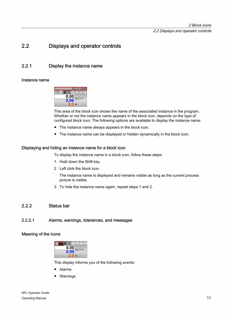
Instance name
This area of the block icon shows the name of the associated instance in the program. Whether or not the instance name appears in the block icon, depends on the type of configured block icon. The following options are available to display the instance name:
● The instance name always appears in the block icon.
● The instance name can be displayed or hidden dynamically in the block icon.
Displaying and hiding an instance name for a block icon To display the instance name in a block icon, follow these steps:
1. Hold down the Shift key.
2. Left click the block icon.
The instance name is displayed and remains visible as long as the current process picture is visible.
3. To hide the instance name again, repeat steps 1 and 2.
2.2.2 Status bar
2.2.2.1 Alarms, warnings, tolerances, and messages
Meaning of the icons
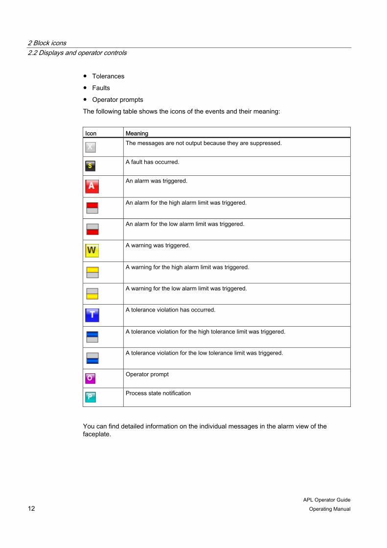
This display informs you of the following events:
● Alarms
● Warnings
2 Block icons 2.2 Displays and operator controls
APL Operator Guide 12 Operating Manual
● Tolerances
● Faults
● Operator prompts
The following table shows the icons of the events and their meaning:
Icon Meaning
The messages are not output because they are suppressed.
A fault has occurred.
An alarm was triggered.
An alarm for the high alarm limit was triggered.
An alarm for the low alarm limit was triggered.
A warning was triggered.
A warning for the high alarm limit was triggered.
A warning for the low alarm limit was triggered.
A tolerance violation has occurred.
A tolerance violation for the high tolerance limit was triggered.
A tolerance violation for the low tolerance limit was triggered.
Operator prompt
Process state notification
You can find detailed information on the individual messages in the alarm view of the faceplate.

2 Block icons 2.2 Displays and operator controls
APL Operator Guide Operating Manual 13
2.2.2.2 Operating modes
Meaning of the icons
This display informs you about the current operating mode. The following table shows the icons of the operating modes and their meaning:
Icon Meaning
Automatic mode In automatic mode, control is performed automatically by the program.
Manual mode In manual mode, you can control the device manually and change the manipulated variable (output signal). The manipulated variable can be analog or binary.
"On" operating mode The "On" operating mode tells you that the device is running. This operating mode is only for devices without manual mode, automatic mode and local mode. You can activate the "On" operating mode in the faceplate when the device is in "Out of service" mode.
Program (controller) In the program mode, the controller can be controlled by applications running on a PC as an OPC client. This allows you to specify the manipulated variables and setpoints externally.
Local mode This operating mode is used for motors, valves and dosing units. The control is performed directly or via a control station that is located "locally".
Out of service The "Out of service" operating mode is available to all devices that have an operating mode switchover and a direct connection to the process (with a connection to a process tag, for example). This operating mode is intended for purposes of maintenance and servicing (replacing the device, for example). All functions of the device are disabled in the "Out of service" operating mode. Incoming and outgoing messages are not generated in this case. Only one operating mode switchover is possible in this operating mode. In the "Out of service" operating mode, no other icons are displayed and no values are shown in the analog value display. An exception is the display of the active messages in the memo view and the display for the maintenance release. These continue to be displayed.

2 Block icons 2.2 Displays and operator controls
APL Operator Guide 14 Operating Manual
Switching operating modes You can use the block icon to switch the operating mode if the appropriate operator permission is available.
Switch the operating mode as follows:
1. Right-click on the icon of the operating mode.
The operating window of the corresponding faceplate opens.
2. Click on the button for the desired operating mode.
3. If acknowledgement is required, click "OK".
For additional information refer to "Auto-Hotspot".
See also Operating window (Page 52)
2.2.2.3 Setpoint specification
Meaning of the icons
This display informs you about the current type of setpoint specification. The following table shows the icons and their meaning:
Icon Meaning
Setting the setpoint internally The setpoint is specified in the faceplate.
External setpoint specification The setpoint is specified in the higher-level controller.
2 Block icons 2.2 Displays and operator controls
APL Operator Guide Operating Manual 15
Switch setpoint specification You can use the block icon to switch the setpoint specification if the appropriate operator permission is available.
1. Right-click on the icon of the setpoint specification.
The operating window of the corresponding faceplate opens.
2. Click the active button to switch the setpoint specification.
3. If acknowledgement is required, click "OK".
For additional information refer to "Operating window (Page 52)".
2.2.2.4 Display of the signal status
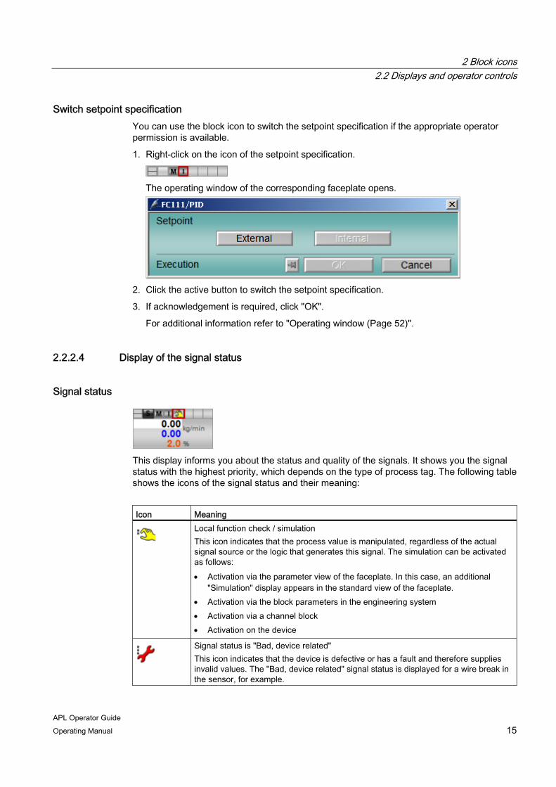
Signal status
This display informs you about the status and quality of the signals. It shows you the signal status with the highest priority, which depends on the type of process tag. The following table shows the icons of the signal status and their meaning:
Icon Meaning
Local function check / simulation This icon indicates that the process value is manipulated, regardless of the actual signal source or the logic that generates this signal. The simulation can be activated as follows: • Activation via the parameter view of the faceplate. In this case, an additional
"Simulation" display appears in the standard view of the faceplate. • Activation via the block parameters in the engineering system • Activation via a channel block • Activation on the device
Signal status is "Bad, device related" This icon indicates that the device is defective or has a fault and therefore supplies invalid values. The "Bad, device related" signal status is displayed for a wire break in the sensor, for example.
2 Block icons 2.2 Displays and operator controls
APL Operator Guide 16 Operating Manual
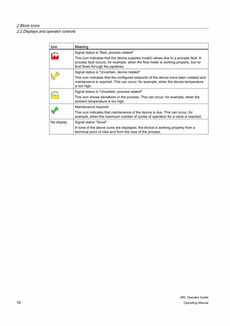
Icon Meaning
Signal status is "Bad, process related" This icon indicates that the device supplies invalid values due to a process fault. A process fault occurs, for example, when the flow meter is working properly, but no fluid flows through the pipelines.
Signal status is "Uncertain, device related" This icon indicates that the configured setpoints of the device have been violated and maintenance is required. This can occur, for example, when the device temperature is too high.
Signal status is "Uncertain, process related" This icon shows deviations in the process. This can occur, for example, when the ambient temperature is too high.
Maintenance required This icon indicates that maintenance of the device is due. This can occur, for example, when the maximum number of cycles of operation for a valve is reached.
No display Signal status "Good" If none of the above icons are displayed, the device is working properly from a technical point of view and from the view of the process.
2 Block icons 2.2 Displays and operator controls
APL Operator Guide Operating Manual 17
2.2.2.5 Tracking and forcing of values and bypasses
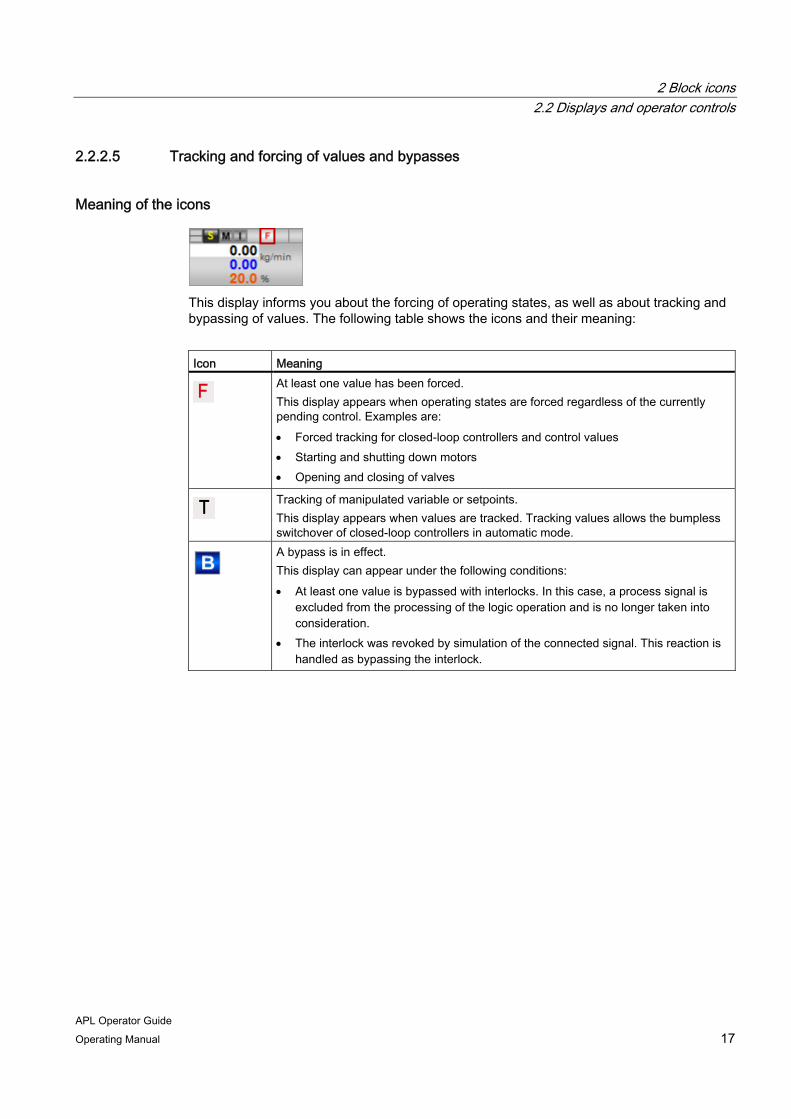
Meaning of the icons
This display informs you about the forcing of operating states, as well as about tracking and bypassing of values. The following table shows the icons and their meaning:
Icon Meaning
At least one value has been forced. This display appears when operating states are forced regardless of the currently pending control. Examples are: • Forced tracking for closed-loop controllers and control values • Starting and shutting down motors • Opening and closing of valves
Tracking of manipulated variable or setpoints. This display appears when values are tracked. Tracking values allows the bumpless switchover of closed-loop controllers in automatic mode.
A bypass is in effect. This display can appear under the following conditions: • At least one value is bypassed with interlocks. In this case, a process signal is
excluded from the processing of the logic operation and is no longer taken into consideration.
• The interlock was revoked by simulation of the connected signal. This reaction is handled as bypassing the interlock.

2 Block icons 2.2 Displays and operator controls
APL Operator Guide 18 Operating Manual
2.2.2.6 Interlocks
Meaning of the icons
This display informs you about pending interlocks of the drive. The following table shows the interlock icons and their meaning:
Icon Meaning
The drive has no interlock.
The drive is interlocked.
The interlock has been passivated.
You can find more detailed information on interlocks under:
● Display of the interlock status (Page 68)
● Interlocks (Page 117)
2.2.2.7 Memo display
Display of a stored message
This display informs you of messages that are stored in the memo view of the faceplate and enabled. For additional information refer to "Opening views of a faceplate (Page 32)".

2 Block icons 2.2 Displays and operator controls
APL Operator Guide Operating Manual 19
2.2.3 Analog value display (PID controller)
2.2.3.1 Layout and functions
Analog value display This area of the block icons shows the following additional information:
1. Process value
2. Setpoint
3. Manipulated variable
You can use the analog display of the block icon to open the operating window of the associated faceplate and manipulate the values as follows:
● Simulate process value (Page 20)
● Change setpoint (Page 21)
● Change manipulated variable (Page 22)
The operating window is closed each time a value is applied. If you want to perform several successive actions in the operating window, you can keep the operating window open by pressing the "Do not close operating range" button:

2 Block icons 2.2 Displays and operator controls
APL Operator Guide 20 Operating Manual
2.2.3.2 Simulate process value
Introduction You can use the block icon to open the associated operating window of the faceplate and enter values in it for process simulation.
Requirement ● Simulation is enabled. This is indicated by the display of signal status in the status bar of
the block icon:
● You have the required operator permissions.
For additional information refer to "Operator permission and enable (Page 29)".
Procedure To simulate the process value, follow these steps:
1. Right-click on the display of the process value.
The operating window of the corresponding faceplate opens.
2. Enter a value for the process simulation.
You can find additional information on changing values in the operating window under "Change values (Page 51)".
3. If acknowledgement is required, click "OK".
For additional information refer to "Operating window (Page 52)".
2 Block icons 2.2 Displays and operator controls
APL Operator Guide Operating Manual 21
2.2.3.3 Change setpoint
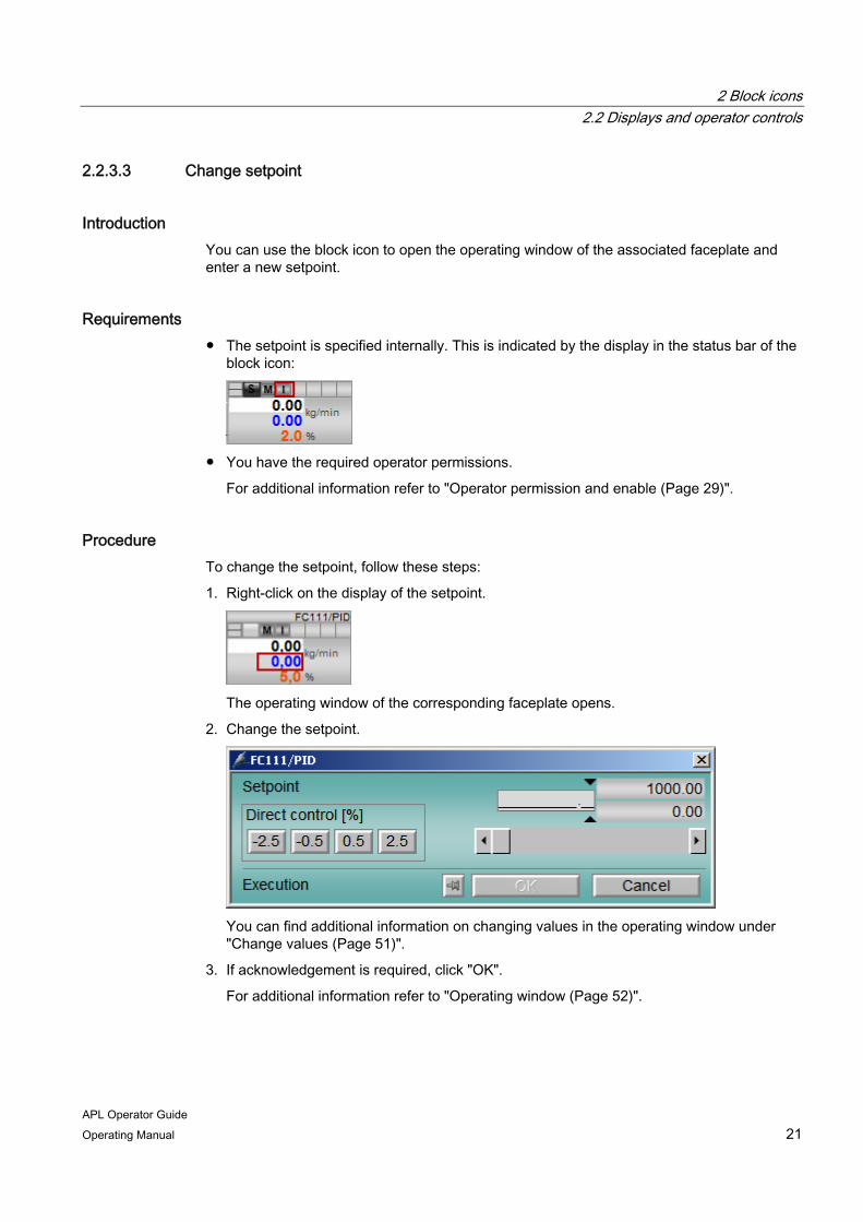
Introduction You can use the block icon to open the operating window of the associated faceplate and enter a new setpoint.
Requirements ● The setpoint is specified internally. This is indicated by the display in the status bar of the
block icon:
● You have the required operator permissions.
For additional information refer to "Operator permission and enable (Page 29)".
Procedure To change the setpoint, follow these steps:
1. Right-click on the display of the setpoint.
The operating window of the corresponding faceplate opens.
2. Change the setpoint.
You can find additional information on changing values in the operating window under "Change values (Page 51)".
3. If acknowledgement is required, click "OK".
For additional information refer to "Operating window (Page 52)".

2 Block icons 2.2 Displays and operator controls
APL Operator Guide 22 Operating Manual
2.2.3.4 Change manipulated variable
Introduction You can use the block icon to open the operating window of the associated faceplate and enter a manipulated variable.
Requirement ● The unit is in manual mode. This is indicated by the display in the status bar of the block
icon:
● You have the required operator permissions.
For additional information refer to "Operator permission and enable (Page 29)".
Procedure To change the manipulated variable, follow these steps:
1. Right-click on the display of the manipulated variable.
The operating window of the corresponding faceplate opens.
2. Change the manipulated variable.
You can find additional information on changing values in the operating window under "Change values (Page 51)".
3. If acknowledgement is required, click "OK".
For additional information refer to "Operating window (Page 52)".

2 Block icons 2.2 Displays and operator controls
APL Operator Guide Operating Manual 23
2.2.4 Status display
Status display
The operating status of a device can be indicated by an operable icon. You can use this icon to open the operating window of the associated faceplate and set the device to a new operating state. You can start a motor or open a valve, for example. The requires that you have the appropriate operator permissions.
Switching the operating mode To set a device to a new operating state, follow these steps:
1. Right-click on the icon of the status display.
The operating window of the corresponding faceplate opens.
2. Click on the button for the desired operating state.
3. If acknowledgement is required, click "OK".

2 Block icons 2.2 Displays and operator controls
APL Operator Guide 24 Operating Manual

APL Operator Guide Operating Manual 25
Faceplates 33.1 Open faceplate
Introduction APL faceplates are displayed in a separate window in process mode and are used to control and monitor process values, trends, messages and parameters.
Procedure To open an APL faceplate, follow these steps:
1. Open the desired process picture.
2. Left-click on the desired block icon.

3 Faceplates 3.1 Open faceplate
APL Operator Guide 26 Operating Manual
The faceplate opens.
See also Operator permission and enable (Page 29)

3 Faceplates 3.2 Layout of faceplates
APL Operator Guide Operating Manual 27
3.2 Layout of faceplates
Layout and functions In comparison to faceplates of the standard libraries, the APL faceplates offer advanced operator controls and displays that reflect the many APL functions. The areas and views in an faceplate vary depending on the type of process tag and the configuration.
An APL faceplate can contain the following operator controls and displays:
1. Displays and operator controls
2. Status displays, additional information (Page 71), jump functions (Page 63)
3. Operating mode (Page 47) , operating state (Page 49) and setpoint specification (Page 56)
4. Interlocking functions (Page 68)
5. Auxiliary values (Page 73)
6. Operator input window (Page 52)

3 Faceplates 3.2 Layout of faceplates
APL Operator Guide 28 Operating Manual
Displays and operator controls An APL faceplate can contain the following displays and operator controls:
1. Group display (Page 65)
2. Locking or unlocking messages (Page 57)
3. Suppressing messages (Page 59)
4. Acknowledge messages (Page 59)
5. Signal status (Page 67)
6. Batch display (Page 73)
7. Not used
8. Release for maintenance (Page 61)
9. Memo display (Page 74)
10. Opening views of a faceplate (Page 32)
11. Switching to the block icon (Page 62)
12. Pinning the faceplate (Page 62)
13. Instance name of the block
Note
You can learn about additional operator controls in the descriptions of the individual devices.

3 Faceplates 3.3 Operating functions of APL faceplates
APL Operator Guide Operating Manual 29
3.3 Operating functions of APL faceplates
3.3.1 Operator permission and enable
3.3.1.1 Operator permission
Introduction Various operator permissions can be assigned to one or more operators specific to the project. The operator permission also depends also on the operating mode and can be specifically assigned to individual process pictures.
The changes you are allowed to make depend on your operator permission and the enabled operation, for example, based on the process involved.
Operator permission level The following operator permission levels are provided and can be assigned to the operator:
● 0: No process control, monitoring only
This operator permission allows the process to be monitored but not controlled.
● 1: Process control (for example, manual and automatic mode switchover, changing setpoints and manipulated variables)
This operator permission allows operation in the standard view of all blocks
as well as input in the ramp and memos view. The "Out of service" mode
cannot be controlled.
● 2: Higher process controlling (for example, changing limits, controller parameters, and monitoring times)
This operator control permission enables all operations in all views of all blocks, including operation in the "Out of service" operating mode.
Exception: The permissions of operator permission level 3.
● 3: Highest process controlling (simulate process values and maintenance release for process tag)
With this operator control permission, simulation can be switched on and off in the parameter view and the process tag for maintenance work can be released.
3.3.1.2 Local operator permission
Introduction Local operator permission can be set for each specific instance; in other words, process tags can be enabled or disabled for use on an operator station independent of one another.
3 Faceplates 3.3 Operating functions of APL faceplates
APL Operator Guide 30 Operating Manual
If local operator permission is lacking, operation of a faceplate on an operator station is usually disabled. When local operator permission is given, operator permission is determined from the operator permission levels and enabled operations.
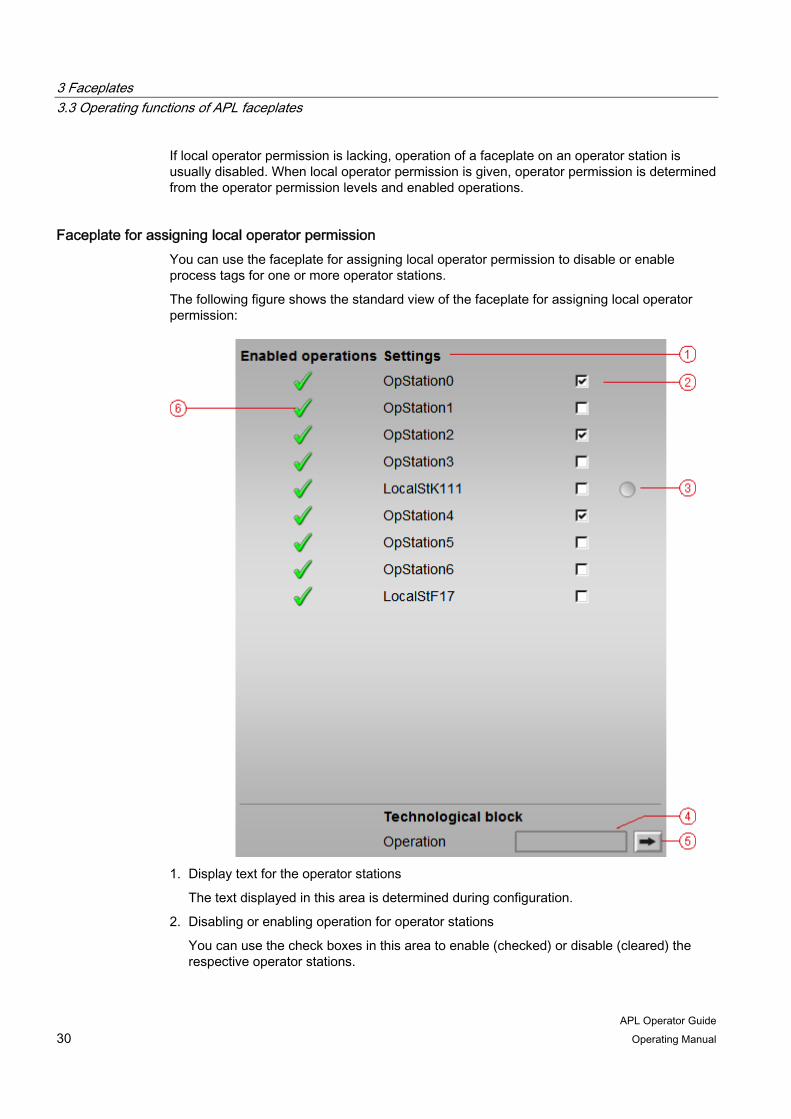
Faceplate for assigning local operator permission You can use the faceplate for assigning local operator permission to disable or enable process tags for one or more operator stations.
The following figure shows the standard view of the faceplate for assigning local operator permission:
1. Display text for the operator stations
The text displayed in this area is determined during configuration.
2. Disabling or enabling operation for operator stations
You can use the check boxes in this area to enable (checked) or disable (cleared) the respective operator stations.
3 Faceplates 3.3 Operating functions of APL faceplates
APL Operator Guide Operating Manual 31
3. Display for the current operator station
4. Display of the operability of a process tag on the current operator station
5. Opening the faceplate of the process tag
6. Enabled operations
The status of the enabled operation is displayed in this area. For additional information refer to "Enabled operations (Page 31)".
The information displayed in the faceplate and control options depend on the configuration.
The faceplate also offers a memo view in addition to the standard view. For additional information refer to "Memo view (Page 45)".
3.3.1.3 Enabled operations
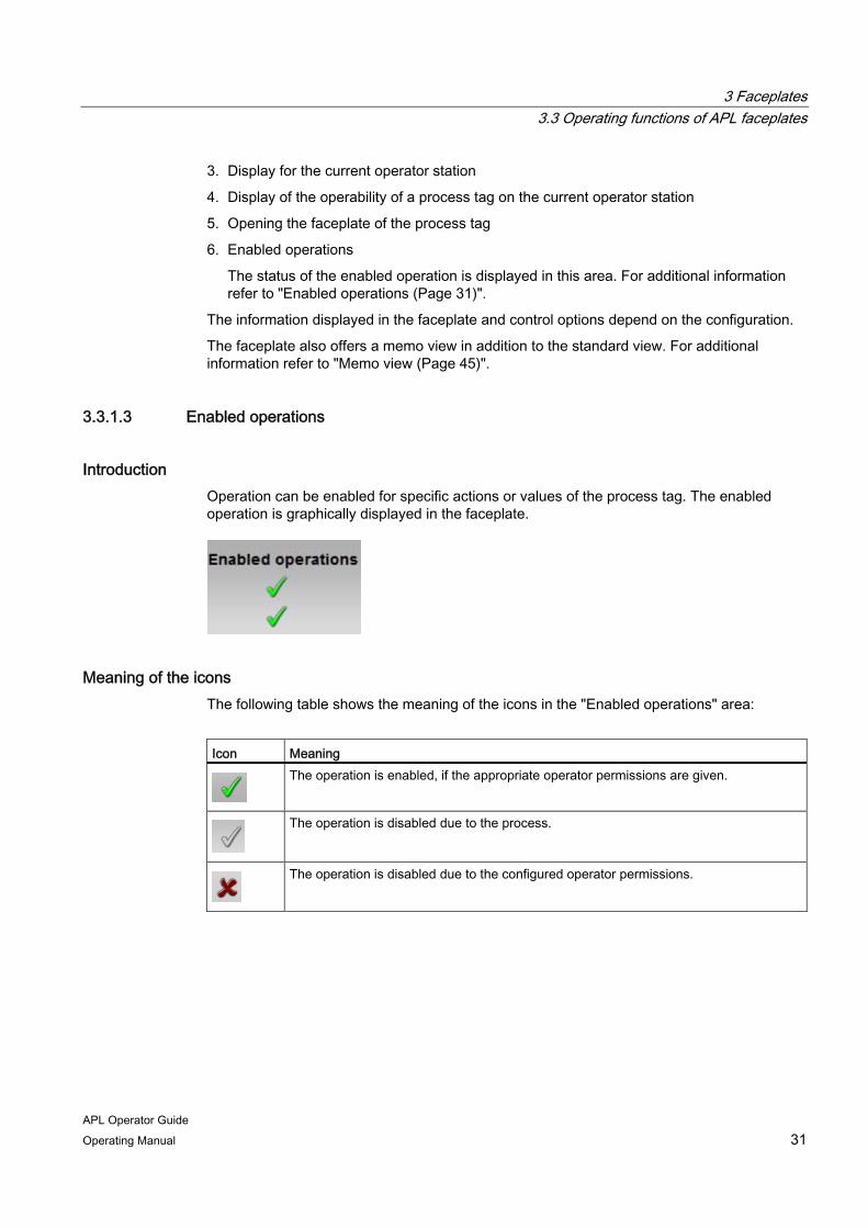
Introduction Operation can be enabled for specific actions or values of the process tag. The enabled operation is graphically displayed in the faceplate.
Meaning of the icons The following table shows the meaning of the icons in the "Enabled operations" area:
Icon Meaning
The operation is enabled, if the appropriate operator permissions are given.
The operation is disabled due to the process.
The operation is disabled due to the configured operator permissions.

3 Faceplates 3.3 Operating functions of APL faceplates
APL Operator Guide 32 Operating Manual
When process messages for a limit are suppressed, the following icon is shown in the limit view of the respective faceplate:
3.3.2 Opening views of a faceplate
3.3.2.1 Overview of the views
Views of a faceplate
You can switch between various views in the faceplate. Depending on the configuration, the following views are available:
Icon Description
Standard view This view shows the most important process information and allows changes to be made to process values, for example, switching the operating mode, forcing an operating state or the specification of a setpoint.
Alarm view In this view, you can monitor and manage the messages that have been triggered by the associated device.
Limit view In this view, you can monitor limits and change them based on the process. Several limit views are possible within a faceplate.
Trend view This view enables you to display process values as in the form of curves, and collect, store and recall them.
Ramp view In this view, you can affect the gradient limits of the setpoint and the ramp modes.
Parameter view The parameter view allows you to monitor and change parameters values, as well as enable or disable simulation. Several parameter views are possible within a faceplate.
Preview This view shows you which parameters you are allowed to operate in the entire faceplate.
Memo view You can leave temporary messages for other OS operators in this view.

3 Faceplates 3.3 Operating functions of APL faceplates
APL Operator Guide Operating Manual 33
Icon Description
Batch view This view shows you whether the device can be controlled using SIMATIC BATCH.
Setpoint view In this view, you can monitor and change setpoints.
Display additional views This button allows you to switch between the views of a faceplate.
More information about views The functions available to the faceplates and their views differ depending on the type of device. You can find additional information on this in the following sections:
● General
– Opening a block view (Page 33)
– Alarm view (Page 37)
– Trend view (Page 41)
– Memo view (Page 45)
– Batch view (Page 47)
● Device-specific
– Motors and valves (Page 77)
– Controller (PID) (Page 95)
– Interlocks (Page 117)
– Dosers (Page 129)
– Monitoring a process tag (Page 159)
3.3.2.2 Opening views
Introduction There are the two ways to open a new view:
● In the current window of the faceplate
● In a new window

3 Faceplates 3.3 Operating functions of APL faceplates
APL Operator Guide 34 Operating Manual
Opening views in the current window of the faceplate To change the view in the current window of the faceplate, follow these steps:
1. Open the faceplate.
2. Left-click on the icon of the view you want to open.
The view opens in the current window of the faceplate.

3 Faceplates 3.3 Operating functions of APL faceplates
APL Operator Guide Operating Manual 35
Opening views in a new window To open a view of the faceplate in a separate window, follow these steps:
1. Open the faceplate.
2. Right-click on the icon of the view you want to open.
3 Faceplates 3.3 Operating functions of APL faceplates
APL Operator Guide 36 Operating Manual
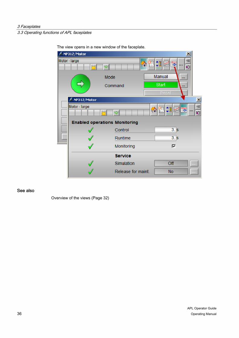
The view opens in a new window of the faceplate.
See also Overview of the views (Page 32)

3 Faceplates 3.3 Operating functions of APL faceplates
APL Operator Guide Operating Manual 37
3.3.2.3 Alarm view
Introduction In the alarm view of a faceplate, you can manage messages that have been triggered by the corresponding process tag. The alarm view consists of the following three areas:
1. Toolbar
2. Message window
3. Status bar
Toolbar The following table shows the meaning of the operator controls and their icons:
Icon Meaning
Single acknowledgment You can acknowledge all messages requiring acknowledgment using this button. If using the multiple selection, the selected messages which require single acknowledgment are not acknowledged.
Confirm All Acknowledges all active, visible messages which require acknowledgment in the message window, unless these require single acknowledgment. If you use the multiple selection, all marked messages are acknowledged, even if the messages are hidden.
3 Faceplates 3.3 Operating functions of APL faceplates
APL Operator Guide 38 Operating Manual
Icon Meaning
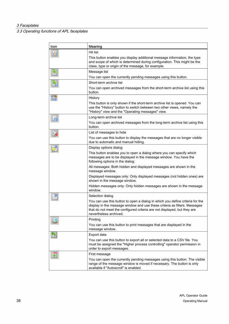
Hit list This button enables you display additional message information, the type and scope of which is determined during configuration. This might be the class, type or origin of the message, for example.
Message list You can open the currently pending messages using this button.
Short-term archive list You can open archived messages from the short-term archive list using this button.
History This button is only shown if the short-term archive list is opened. You can use the "History" button to switch between two other views, namely the "History" view and the "Operating messages" view.
Long-term archive list You can open archived messages from the long-term archive list using this button.
List of messages to hide You can use this button to display the messages that are no longer visible due to automatic and manual hiding.
Display options dialog This button enables you to open a dialog where you can specify which messages are to be displayed in the message window. You have the following options in the dialog: All messages: Both hidden and displayed messages are shown in the message window. Displayed messages only: Only displayed messages (not hidden ones) are shown in the message window. Hidden messages only: Only hidden messages are shown in the message window.
Selection dialog You can use this button to open a dialog in which you define criteria for the display in the message window and use these criteria as filters. Messages that do not meet the configured criteria are not displayed, but they are nevertheless archived.
Printing You can use this button to print messages that are displayed in the message window.
Export data You can use this button to export all or selected data to a CSV file. You must be assigned the "Higher process controlling" operator permission in order to export messages.
First message You can open the currently pending messages using this button. The visible range of the message window is moved if necessary. The button is only available if "Autoscroll" is enabled.

3 Faceplates 3.3 Operating functions of APL faceplates
APL Operator Guide Operating Manual 39
Icon Meaning
Previous message This button allows you to select the message above the currently selected message in the message window. The visible range of the message window is moved if necessary. The button is only available if the "Autoscroll" function is enabled.
Next message This button allows you to select the message below the currently selected message in the message window. The visible range of the message window is moved if necessary. The button is only available if the "Autoscroll" function is enabled.
Last message This button allows you to select the last of the currently pending messages. The visible range of the message window is moved if necessary. The button is only available if the "Autoscroll" function is enabled.
Infotext dialog You can use this button to open a dialog that provides additional information about the currently selected message.
Comments dialog You can use this button to open a dialog and enter information about the currently selected message in its input box.
Autoscroll function You can use this button to enable or disable the "Autoscroll" function. If the "Autoscroll" function is enabled, the latest message is selected in the message window. The visible range of the message window is moved if necessary. If the "Autoscroll" function is disabled, a newly arrived message is not selected. The visible range of the message window is not modified. Messages can only be selected explicitly if "Autoscroll" is enabled.
Hide message You can use this button to hide messages that are selected in the message window. You must be assigned the "Higher process controlling" operator permission in order to hide messages. Hidden messages can be displayed in the message window using the "List of messages to be hidden" button.
Unhide messages This button allows you to show the message you have selected in the "List of messages to be hidden". The messages are removed from the "List of messages to be hidden".
3 Faceplates 3.3 Operating functions of APL faceplates
APL Operator Guide 40 Operating Manual
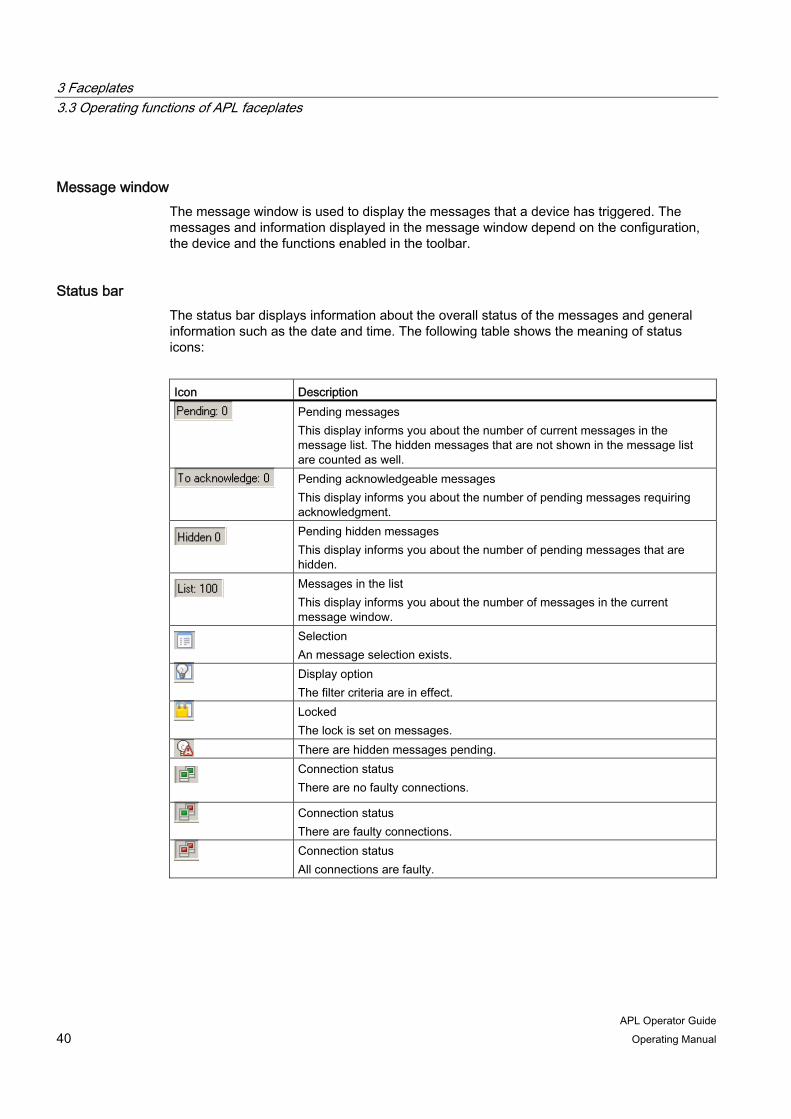
Message window The message window is used to display the messages that a device has triggered. The messages and information displayed in the message window depend on the configuration, the device and the functions enabled in the toolbar.
Status bar The status bar displays information about the overall status of the messages and general information such as the date and time. The following table shows the meaning of status icons:
Icon Description
Pending messages This display informs you about the number of current messages in the message list. The hidden messages that are not shown in the message list are counted as well.
Pending acknowledgeable messages This display informs you about the number of pending messages requiring acknowledgment.
Pending hidden messages This display informs you about the number of pending messages that are hidden.
Messages in the list This display informs you about the number of messages in the current message window.
Selection An message selection exists.
Display option The filter criteria are in effect.
Locked The lock is set on messages.
There are hidden messages pending.
Connection status There are no faulty connections.
Connection status There are faulty connections.
Connection status All connections are faulty.
3 Faceplates 3.3 Operating functions of APL faceplates
APL Operator Guide Operating Manual 41
3.3.2.4 Trend view
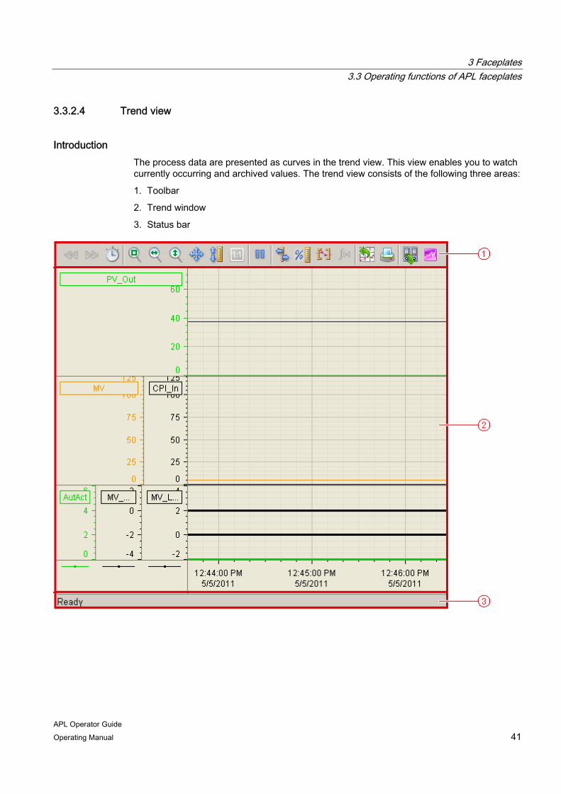
Introduction The process data are presented as curves in the trend view. This view enables you to watch currently occurring and archived values. The trend view consists of the following three areas:
1. Toolbar
2. Trend window
3. Status bar
3 Faceplates 3.3 Operating functions of APL faceplates
APL Operator Guide 42 Operating Manual
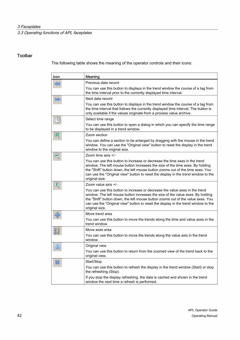
Toolbar The following table shows the meaning of the operator controls and their icons:
Icon Meaning
Previous data record You can use this button to displays in the trend window the course of a tag from the time interval prior to the currently displayed time interval.
Next data record You can use this button to displays in the trend window the course of a tag from the time interval that follows the currently displayed time interval. The button is only available if the values originate from a process value archive.
Select time range You can use this button to open a dialog in which you can specify the time range to be displayed in a trend window.
Zoom section You can define a section to be enlarged by dragging with the mouse in the trend window. You can use the "Original view" button to reset the display in the trend window to the original size.
Zoom time axis +/- You can use this button to increase or decrease the time axes in the trend window. The left mouse button increases the size of the time axes. By holding the "Shift" button down, the left mouse button zooms out of the time axes. You can use the "Original view" button to reset the display in the trend window to the original size.
Zoom value axis +/- You can use this button to increase or decrease the value axes in the trend window. The left mouse button increases the size of the value axes. By holding the "Shift" button down, the left mouse button zooms out of the value axes. You can use the "Original view" button to reset the display in the trend window to the original size.
Move trend area You can use this button to move the trends along the time and value axes in the trend window.
Move axes area You can use this button to move the trends along the value axis in the trend window.
Original view You can use this button to return from the zoomed view of the trend back to the original view.
Start/Stop You can use this button to refresh the display in the trend window (Start) or stop the refreshing (Stop). If you stop the display refreshing, the data is cached and shown in the trend window the next time a refresh is performed.

3 Faceplates 3.3 Operating functions of APL faceplates
APL Operator Guide Operating Manual 43
Icon Meaning
Ruler This button queries the coordinate points of a trend. The trend data is displayed in the ruler window.
Relative axis You can use this button to switch from displaying the absolute values to the percentage representation of the value axis. The high and low limits for the trend correspond with a range of 0 to 100%.
Define statistical range You can use this button to define the time range for calculating the statistics in the trend window.
Calculate statistics You can use this button to display the statistics. The displayed values refer to a selected trend with the configured calculation time range.
Export data You can use this button to export all or selected data to a "CSV" file. With the respective authorization, you are also allowed to select the file and the directory for the export.
Printing Click this button to print the trend shown in the trend window.
Archive tag / online tag This button allows you to toggle between archive tags and online tags. The status bar shows if the trend view is working with online data or archive data.
Scatter plot (for closed-loop controllers) You can use this button to open the "Scatter plot" window. It shows a coordinate system with the process value on the value axis and the manipulated variable or position feedback on the X axis. A new value pair is entered into the coordinate system with each cycle.
You can find additional information the operator controls of the trend view in the "WinCC Information System" online help.
Trend window The trend window is used for display process values in the form of curves. The values displayed in the trend window depend on the configuration, the device and the functions enabled in the toolbar.
2 or 3 coordinate systems are shown for closed-loop controllers in the trend window, depending on the configuration. They can include the following information:
● Setpoint trend, process value trend
● Manipulated variable trend, control performance index trend
● Binary trend via automatic/manual operating mode, manipulated variable at high or low limit

3 Faceplates 3.3 Operating functions of APL faceplates
APL Operator Guide 44 Operating Manual
Status bar The status bar displays information about the overall status and general information such as the date and time. The following table shows the meaning of status icons:
Icon Meaning
Connection status No faulty connections
Connection status Faulty connections exist
Connection status All connections are faulty
Time Base Shows the time base used in the display of times. Shows the system date.
Shows the system time.
Note
You can double-click on the icon for the connection status to open the "Status of the data connections" window, in which the name, status and tag name of the data connection are listed.

3 Faceplates 3.3 Operating functions of APL faceplates
APL Operator Guide Operating Manual 45
3.3.2.5 Memo view
Introduction In memo view, you can leave temporary messages for other operators, for example, when a shift changes. To do this, you write a text and open the memo display. The memo display signals that a new message is present and shows it as follows:
● In the block icon
● In the faceplate
Leaving a message To write a memo and the open the memo display, follow these steps:
1. Open the desired faceplate.
2. Open the memo view.
3. Write a memo in the text box.

3 Faceplates 3.3 Operating functions of APL faceplates
APL Operator Guide 46 Operating Manual
4. To open the memo display for the written message, click the check box "Active memo".
The operating window is opened as an extension of the faceplate.
5. Click "On".
6. If acknowledgement is required, click "OK".
The memo is activated. The memo display appears in the block icon and in the faceplate.
Delete memo To write a memo and the open the memo display, follow these steps:
1. Open the desired faceplate.
2. Open the memo view.
3. To delete the memo, select the text in the text box and press the "Delete" key on the keyboard.
The memo text is deleted.
4. To deactivate the memo display, click the check box "Active memo".
The operating window is opened as an extension of the faceplate.
5. Click "Off".
6. If acknowledgement is required, click "OK".
The memo is deactivated. The memo display disappears in the block icon and in the faceplate.

3 Faceplates 3.3 Operating functions of APL faceplates
APL Operator Guide Operating Manual 47
3.3.2.6 Batch view
Batch allocation Batch view contains detailed information on the batch allocation. This view does not allow you to make any changes.
The batch view consists of the following areas:
1. Enabled: This area shows you if the device is enabled for operation via SIMATIC BATCH.
2. Allocated: This area shows if the device is currently in use by SIMATIC BATCH.
3. Batch name: This area shows you the name of the batch that is currently running.
4. Batch ID: This area shows the identification number of the batch that is currently running.
5. Batch step: This area shows you the step number for the batch that is currently running.
3.3.3 Switching operating modes
Overview of the operator modes Depending on the type of device you are operating, the following operating modes may be available:
● Automatic mode In automatic mode, control of the device is performed automatically by the program.
● Manual mode In manual mode, you can control the device manually and change the manipulated variable (output signal). The manipulated variable can be analog or binary.
3 Faceplates 3.3 Operating functions of APL faceplates
APL Operator Guide 48 Operating Manual
● Local mode This operating mode is used for motors, valves and dosing units. The control settings are made directly or via a control station that is located "locally".
● Program mode for closed-loop controllers
In the program mode, the controller can be controlled by applications running on a PC as an OPC client. This allows you to specify the manipulated variables and setpoints externally.
● On The "On" operating mode tells you that the device is running. This operating mode is only for devices without manual mode, automatic mode and local mode. You can activate the "On" operating mode in the faceplate when the device is in "Out of service" mode.
● Out of service
The "Out of service" operating mode is available to all devices that have an operating mode switchover and a direct connection to the process (with a connection to a process tag, for example). This operating mode is intended for purposes of maintenance and servicing (replacing the device, for example). All functions of the device are disabled in the "Out of service" operating mode. Incoming and outgoing messages are not generated in this case. Only one operating mode switchover is possible in this operating mode.
Requirement You have the required operator permissions.
For additional information refer to "Operator permission and enable (Page 29)".
Procedure To switch the operating mode, follow these steps:
1. Open the faceplate.
3 Faceplates 3.3 Operating functions of APL faceplates
APL Operator Guide Operating Manual 49
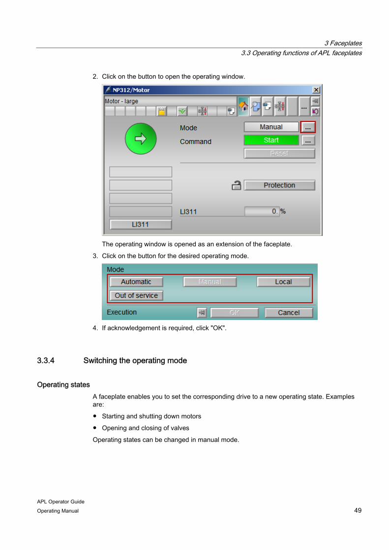
2. Click on the button to open the operating window.
The operating window is opened as an extension of the faceplate.
3. Click on the button for the desired operating mode.
4. If acknowledgement is required, click "OK".
3.3.4 Switching the operating mode
Operating states A faceplate enables you to set the corresponding drive to a new operating state. Examples are:
● Starting and shutting down motors
● Opening and closing of valves
Operating states can be changed in manual mode.

3 Faceplates 3.3 Operating functions of APL faceplates
APL Operator Guide 50 Operating Manual
Requirement You have the required operator permissions.
For additional information refer to "Operator permission and enable (Page 29)".
Procedure To set the device to a new operating state, follow these steps:
1. Open the faceplate.
2. Click on the button to open the operating window.
The operating window is opened as an extension of the faceplate.
3. Click on the button for the desired operating state.
4. If acknowledgement is required, click "OK".
For additional information refer to "Operator permission and enable (Page 29)".

3 Faceplates 3.3 Operating functions of APL faceplates
APL Operator Guide Operating Manual 51
3.3.5 Change values
3.3.5.1 Value representations
Value representation in a faceplate The capability to edit values in the faceplate depends on the process, and on the configured enabled operation and operator permission. The faceplate provides a graphic indication as to whether or not you can change a value. The icons for the signal status enable you also to detect whether a value is incorrect or simulated.
The following table shows the value representation in the faceplate:
Display Meaning
Value can be edited You can change the value. The value can be entered in a separate operating window. For additional information refer to "Operating window (Page 52)" and "Change values (Page 53)".
Value cannot be edited You cannot change the value, because you do not have the appropriate operator permissions.
Passivated value The value has been passivated during configuration.
Internal simulation The value is simulated. The simulation was activated via the current faceplate and displayed as additional information in the standard view. With internal simulation, you can specify a simulation value.
External simulation The value is simulated. The simulation was activated in the configuration via a channel block or on the field device. You cannot specify the simulation value.
Bad value The value is incorrect and cannot be edited.
3 Faceplates 3.3 Operating functions of APL faceplates
APL Operator Guide 52 Operating Manual
3.3.5.2 Operating window
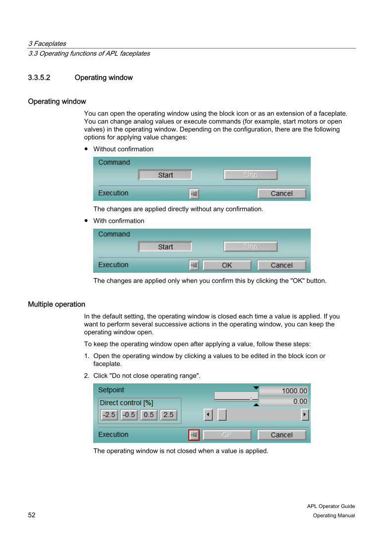
Operating window You can open the operating window using the block icon or as an extension of a faceplate. You can change analog values or execute commands (for example, start motors or open valves) in the operating window. Depending on the configuration, there are the following options for applying value changes:
● Without confirmation
The changes are applied directly without any confirmation.
● With confirmation
The changes are applied only when you confirm this by clicking the "OK" button.
Multiple operation In the default setting, the operating window is closed each time a value is applied. If you want to perform several successive actions in the operating window, you can keep the operating window open.
To keep the operating window open after applying a value, follow these steps:
1. Open the operating window by clicking a values to be edited in the block icon or faceplate.
2. Click "Do not close operating range".
The operating window is not closed when a value is applied.

3 Faceplates 3.3 Operating functions of APL faceplates
APL Operator Guide Operating Manual 53
3.3.5.3 Change values
Introduction In the faceplate, you can change analog values and execute commands, thereby influencing the process.
The operating window offers the following options for changing analog values:
● Input box
● Slider
● Buttons
You can find information about executing commands in the section "Switching operating modes (Page 47)"
Requirements You have the required operator permissions.
For additional information refer to "Operator permission and enable (Page 29)".
Changing an analog value via an input box To change an analog value via the input box in the operating window, follow these steps:
1. Open the faceplate.

3 Faceplates 3.3 Operating functions of APL faceplates
APL Operator Guide 54 Operating Manual
2. Click the input box of the value to be changed.
The operating window is opened as an extension of the faceplate.
3. Click the input box and enter the required value using the keyboard.
4. Confirm your selection with the Return key.
5. If additional confirmation is required, click "OK".

3 Faceplates 3.3 Operating functions of APL faceplates
APL Operator Guide Operating Manual 55
Changing an analog value via a slider To change an analog value via the slider in the operating window, follow these steps:
1. Click the input box of the value to be changed.
The operating window is opened as an extension of the faceplate.
2. Move the slider until the desired value is shown in the input box.
3. If acknowledgement is required for the value entered, click "OK".
Changing an analog value via buttons To change an analog value via the buttons in the operating window, follow these steps:
1. Click the input box of the value to be changed.
The operating window is opened as an extension of the faceplate.
2. Click the desired button.
The value is immediately changed and applied. It is no longer necessary to confirm
this value.
3 Faceplates 3.3 Operating functions of APL faceplates
APL Operator Guide 56 Operating Manual
3.3.6 Switch setpoint specification
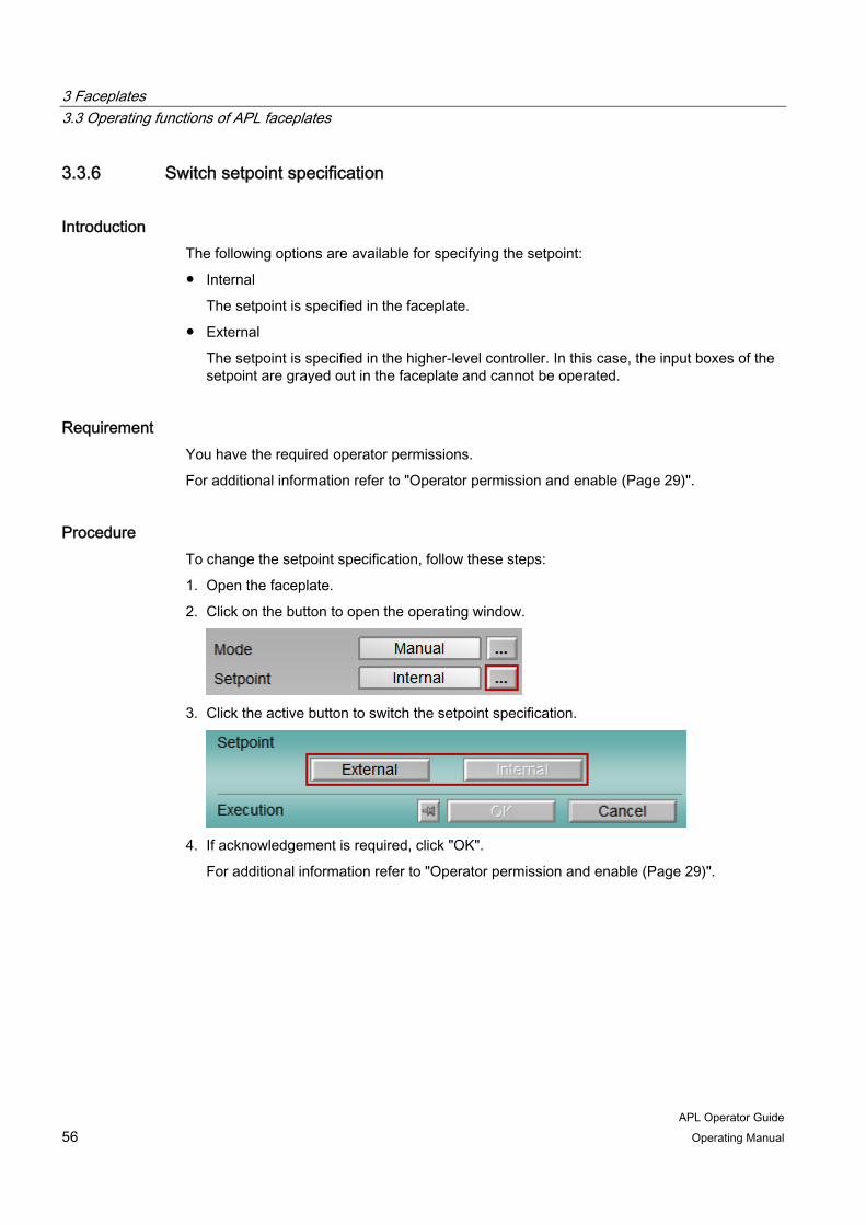
Introduction The following options are available for specifying the setpoint:
● Internal
The setpoint is specified in the faceplate.
● External
The setpoint is specified in the higher-level controller. In this case, the input boxes of the setpoint are grayed out in the faceplate and cannot be operated.
Requirement You have the required operator permissions.
For additional information refer to "Operator permission and enable (Page 29)".
Procedure To change the setpoint specification, follow these steps:
1. Open the faceplate.
2. Click on the button to open the operating window.
3. Click the active button to switch the setpoint specification.
4. If acknowledgement is required, click "OK".
For additional information refer to "Operator permission and enable (Page 29)".

3 Faceplates 3.3 Operating functions of APL faceplates
APL Operator Guide Operating Manual 57
3.3.7 Edit messages
3.3.7.1 Locking or unlocking messages
Locking or unlocking messages In the faceplate, you can lock or unlock the messages triggered by the corresponding device. The locking of the messages is depicted graphically in the group display.
No more new messages are generated during the locked phase. Messages that have previously occurred are no longer displayed as well in the alarm view of the faceplate.
When you unlock the messages, the messages in the group display reappear and new messages are generated. Alarms generated in the locked phase are displayed when you enable the alarm function.
Lock messages To lock messages of a device using the faceplate, follow these steps:
1. Open the faceplate.
2. Click "Lock/unlock messages".

3 Faceplates 3.3 Operating functions of APL faceplates
APL Operator Guide 58 Operating Manual
The messages are locked. The group display shows the "x" symbol during the locked phase.
Unlock messages
To unlock the messages of a device, follow these steps:
1. Open the faceplate.
2. Click "Lock/unlock messages".
The messages are unlocked and appear in the group display.

3 Faceplates 3.3 Operating functions of APL faceplates
APL Operator Guide Operating Manual 59
3.3.7.2 Suppressing messages
Suppressing messages You can see if the "Suppress process messages" function is checked in the display in the faceplate.
If the function is enabled and depending on the configuration, the following messages may be suppressed:
● All existing messages
● All messages except process control messages
When process messages for a limit are suppressed, the following icon is shown in the limit view of the respective faceplate:
3.3.7.3 Acknowledge messages
Introduction In the faceplate, you can acknowledge all messages triggered by the corresponding device.
Requirement You have the required operator permissions.
For additional information refer to "Operator permission and enable (Page 29)".
Procedure To acknowledge all messages for a device, follow these steps:
1. Open the faceplate.
2. Click "Acknowledge error".
The messages are acknowledged.

3 Faceplates 3.3 Operating functions of APL faceplates
APL Operator Guide 60 Operating Manual
3.3.8 Activate or deactivate simulation
Introduction Simulation is primarily used as a tool for commissioning and servicing in the plant. For example, values can be tracked without activating monitoring functions. Simulation does not influence the technological functions of the device. During simulation, all process-relevant output signals are given the "Simulation" status and the following messages are displayed in the block icon and faceplate:
● In the faceplate and the block icon
● In the standard view of the faceplate
Requirement You have the required operator permissions.
For additional information refer to "Operator permission and enable (Page 29)".
Procedure To activate or deactivate the simulation, follow these steps:
1. Open the faceplate.
2. Switch to the parameter view.
3. Click on the button to open the operating window.
The operating window is opened as an extension of the faceplate.
4. Click 'On' to activate simulation or "Off" to deactivate it.
5. If acknowledgement is required, click "OK".
For additional information refer to "Operating window (Page 52)".
3 Faceplates 3.3 Operating functions of APL faceplates
APL Operator Guide Operating Manual 61
3.3.9 Activate or deactivate release for maintenance
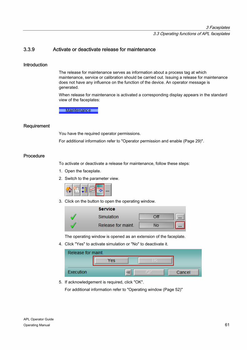
Introduction The release for maintenance serves as information about a process tag at which maintenance, service or calibration should be carried out. Issuing a release for maintenance does not have any influence on the function of the device. An operator message is generated.
When release for maintenance is activated a corresponding display appears in the standard view of the faceplates:
Requirement You have the required operator permissions.
For additional information refer to "Operator permission and enable (Page 29)".
Procedure To activate or deactivate a release for maintenance, follow these steps:
1. Open the faceplate.
2. Switch to the parameter view.
3. Click on the button to open the operating window.
The operating window is opened as an extension of the faceplate.
4. Click "Yes" to activate simulation or "No" to deactivate it.
5. If acknowledgement is required, click "OK".
For additional information refer to "Operating window (Page 52)"
3 Faceplates 3.3 Operating functions of APL faceplates
APL Operator Guide 62 Operating Manual
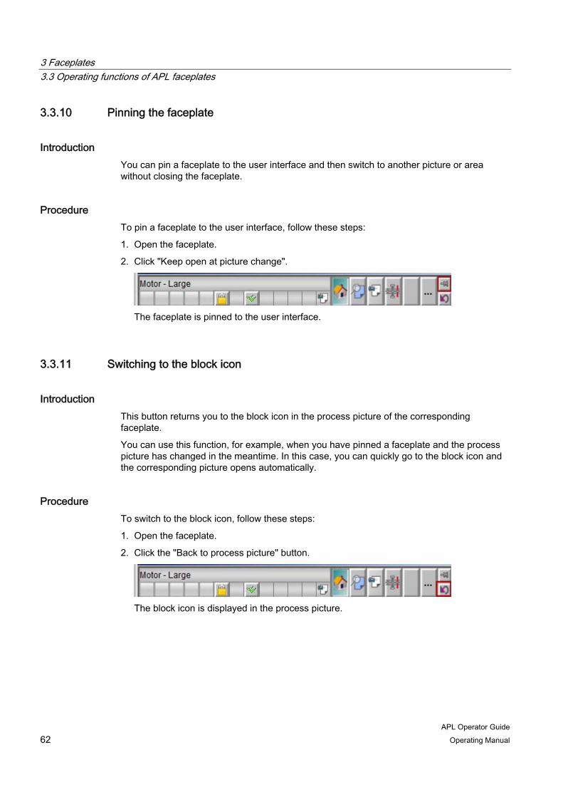
3.3.10 Pinning the faceplate
Introduction You can pin a faceplate to the user interface and then switch to another picture or area without closing the faceplate.
Procedure To pin a faceplate to the user interface, follow these steps:
1. Open the faceplate.
2. Click "Keep open at picture change".
The faceplate is pinned to the user interface.
3.3.11 Switching to the block icon
Introduction This button returns you to the block icon in the process picture of the corresponding faceplate.
You can use this function, for example, when you have pinned a faceplate and the process picture has changed in the meantime. In this case, you can quickly go to the block icon and the corresponding picture opens automatically.
Procedure To switch to the block icon, follow these steps:
1. Open the faceplate.
2. Click the "Back to process picture" button.
The block icon is displayed in the process picture.

3 Faceplates 3.3 Operating functions of APL faceplates
APL Operator Guide Operating Manual 63
3.3.12 Opening additional faceplates
Introduction Depending on the configuration, the faceplates have one or two buttons that enable other faceplates to be opened.
Requirement ● At least one button for opening other faceplates is configured.
● You have the required operator permissions.
For additional information refer to "Operator permission and enable (Page 29)".
Procedure To open another faceplate, follow these steps:
1. Open the faceplate.
2. Open the standard view.
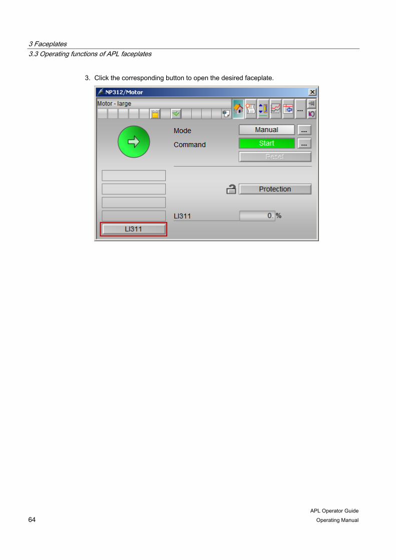
3 Faceplates 3.3 Operating functions of APL faceplates
APL Operator Guide 64 Operating Manual
3. Click the corresponding button to open the desired faceplate.
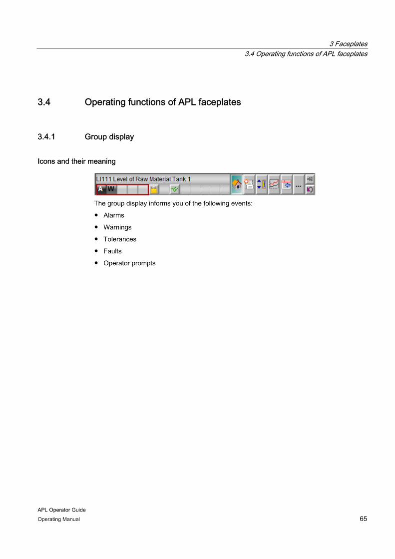
3 Faceplates 3.4 Operating functions of APL faceplates
APL Operator Guide Operating Manual 65
3.4 Operating functions of APL faceplates
3.4.1 Group display
Icons and their meaning
The group display informs you of the following events:
● Alarms
● Warnings
● Tolerances
● Faults
● Operator prompts

3 Faceplates 3.4 Operating functions of APL faceplates
APL Operator Guide 66 Operating Manual
The following table shows the icons shown in the group display and their meaning:
Icon Meaning
No messages are output.
A fault has occurred.
An alarm was triggered.
An alarm for the high alarm limit was triggered.
An alarm for the low alarm limit was triggered.
A warning was triggered.
A warning for the low alarm limit was triggered.
A warning for the high alarm limit was triggered.
A tolerance violation has occurred.
A tolerance violation for the high tolerance limit was triggered.
A tolerance violation for the low tolerance limit was triggered.
Operator prompt
Process state notification

3 Faceplates 3.4 Operating functions of APL faceplates
APL Operator Guide Operating Manual 67
3.4.2 Display of the signal status
Signal status
This display informs you about the status and quality of the signals. It shows you the signal status with the highest priority, which depends on the type of device. The following table shows the icons of the signal status and their meaning:
Icon Meaning
Local function check / simulation This icon indicates that the process value is manipulated, regardless of the actual signal source or the logic that generates this signal. The simulation can be activated as follows: • Activation via the parameter view of the faceplate. In this case, an additional
"Simulation" display appears in the standard view of the faceplate. • Activation via the configuration • Activation via a channel block • Activation on the device
Signal status is "Bad, device related" This icon indicates that the device is defective or has a fault and therefore supplies invalid values. The "Bad, device related" signal status is displayed for a wire break in the sensor, for example.
Signal status is "Bad, process related" This icon indicates that the device supplies invalid values due to a process fault. A process fault occurs, for example, when the flow meter is working properly, but no fluid flows through the pipelines.
Signal status is "Uncertain, device related" This icon indicates that the configured setpoints of the device have been violated and maintenance is required. This can occur, for example, when the device temperature is too high.
Signal status is "Uncertain, process related" This icon shows deviations in the process. This can occur, for example, when the ambient temperature is too high.
Maintenance required This icon indicates that maintenance of the device is due. This can occur, for example, when the maximum number of cycles of operation for a valve is reached.
No display Signal status "Good" If none of the above icons are displayed, the device is working properly from a technical point of view and from the view of the process.
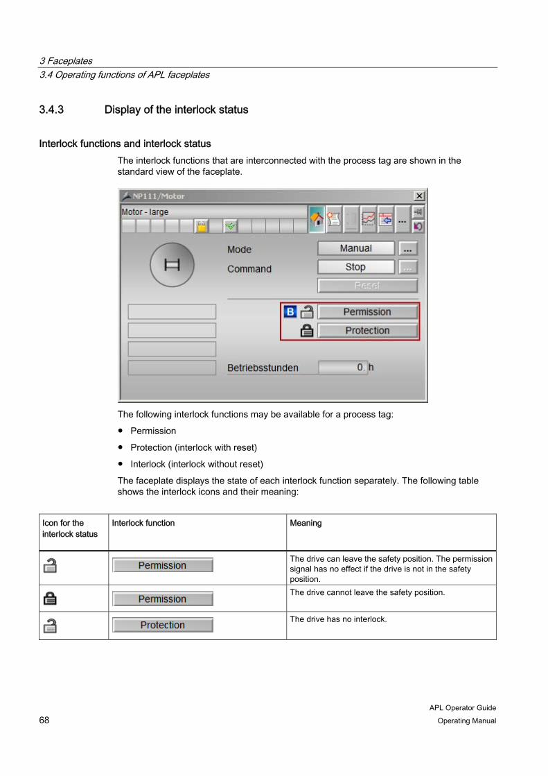
3 Faceplates 3.4 Operating functions of APL faceplates
APL Operator Guide 68 Operating Manual
3.4.3 Display of the interlock status
Interlock functions and interlock status The interlock functions that are interconnected with the process tag are shown in the standard view of the faceplate.
The following interlock functions may be available for a process tag:
● Permission
● Protection (interlock with reset)
● Interlock (interlock without reset)
The faceplate displays the state of each interlock function separately. The following table shows the interlock icons and their meaning:
Icon for the interlock status
Interlock function Meaning
The drive can leave the safety position. The permission signal has no effect if the drive is not in the safety position.
The drive cannot leave the safety position.
The drive has no interlock.
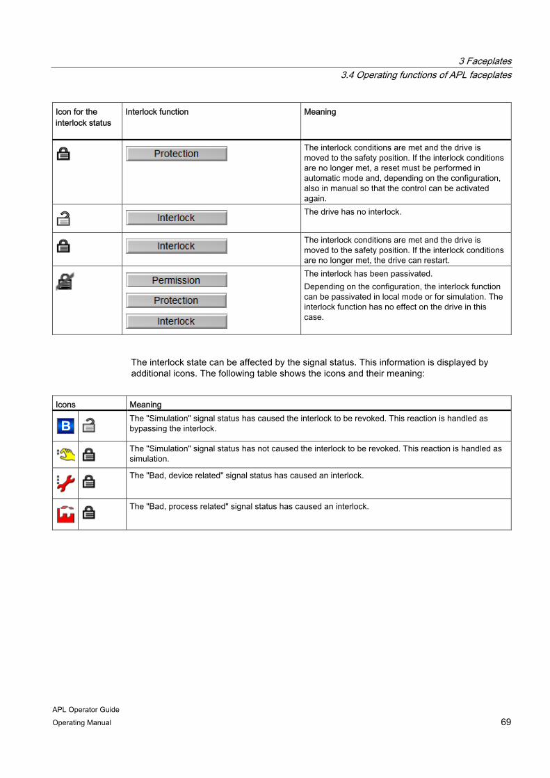
3 Faceplates 3.4 Operating functions of APL faceplates
APL Operator Guide Operating Manual 69
Icon for the interlock status
Interlock function Meaning
The interlock conditions are met and the drive is moved to the safety position. If the interlock conditions are no longer met, a reset must be performed in automatic mode and, depending on the configuration, also in manual so that the control can be activated again.
The drive has no interlock.
The interlock conditions are met and the drive is moved to the safety position. If the interlock conditions are no longer met, the drive can restart.
The interlock has been passivated. Depending on the configuration, the interlock function can be passivated in local mode or for simulation. The interlock function has no effect on the drive in this case.
The interlock state can be affected by the signal status. This information is displayed by additional icons. The following table shows the icons and their meaning:
Icons Meaning
The "Simulation" signal status has caused the interlock to be revoked. This reaction is handled as bypassing the interlock.
The "Simulation" signal status has not caused the interlock to be revoked. This reaction is handled as simulation.
The "Bad, device related" signal status has caused an interlock.
The "Bad, process related" signal status has caused an interlock.
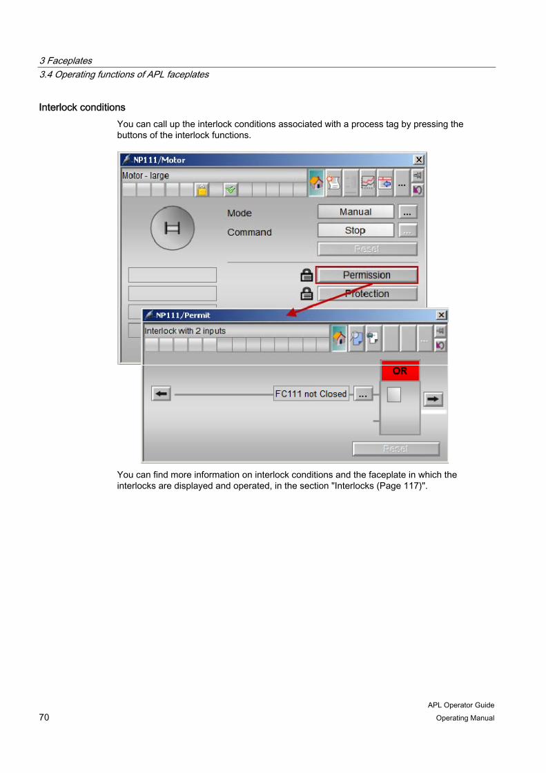
3 Faceplates 3.4 Operating functions of APL faceplates
APL Operator Guide 70 Operating Manual
Interlock conditions You can call up the interlock conditions associated with a process tag by pressing the buttons of the interlock functions.
You can find more information on interlock conditions and the faceplate in which the interlocks are displayed and operated, in the section "Interlocks (Page 117)".

3 Faceplates 3.4 Operating functions of APL faceplates
APL Operator Guide Operating Manual 71
3.4.4 Status display and additional information
Status display
This display shows the status of the blocks in symbolic form. A variety of icons are used to represent the various types of equipment (motors, valves). You can find additional information on this in the following sections:
● Motors and valves (Page 77)
● Controller (PID) (Page 95)
● Dosers (Page 129)

3 Faceplates 3.4 Operating functions of APL faceplates
APL Operator Guide 72 Operating Manual
Additional information
The additional information serves as a guide and indicates the state of the process tag. This area shows the following information:
● Internal simulation
You can find additional information about simulation under "Activate or deactivate simulation (Page 60)".
● Maintenance
You can find additional information about release for maintenance under "Activate or deactivate release for maintenance (Page 61)".
● Device-specific Information
Additional information related to device status are displayed in the faceplate depending on the type of equipment. You can find additional information under:
– Motors and valves (Page 77)
– Controller (PID) (Page 95)
– Dosers (Page 129)
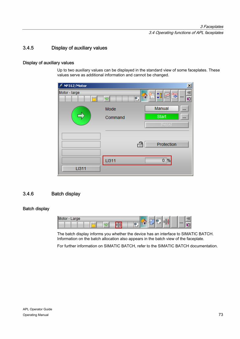
3 Faceplates 3.4 Operating functions of APL faceplates
APL Operator Guide Operating Manual 73
3.4.5 Display of auxiliary values
Display of auxiliary values Up to two auxiliary values can be displayed in the standard view of some faceplates. These values serve as additional information and cannot be changed.
3.4.6 Batch display
Batch display
The batch display informs you whether the device has an interface to SIMATIC BATCH. Information on the batch allocation also appears in the batch view of the faceplate.
For further information on SIMATIC BATCH, refer to the SIMATIC BATCH documentation.

3 Faceplates 3.4 Operating functions of APL faceplates
APL Operator Guide 74 Operating Manual
3.4.7 Memo display
Display of a stored message
The memo view informs you whether a memo has been stored and activated in the memo view. For additional information refer to "Opening views of a faceplate (Page 32)"

3 Faceplates 3.4 Operating functions of APL faceplates
APL Operator Guide Operating Manual 75


APL Operator Guide Operating Manual 77
Motors and valves 44.1 Standard view
4.1.1 Layout and functions
Standard view The standard view contains the basic functions for operating a device. The following figure shows the display and operator controls in the standard view for motors and valves:
1. Switching operating modes
You can switch between the following operating modes for motors and valves:
– Manual mode
– Automatic mode
– Local mode
– Out of service
For additional information on the operating modes, refer to "Switching operating modes (Page 47)"
2. Switching the operating mode
– Starting and stopping a motor (Page 78)
– Opening and closing of valves (Page 80)
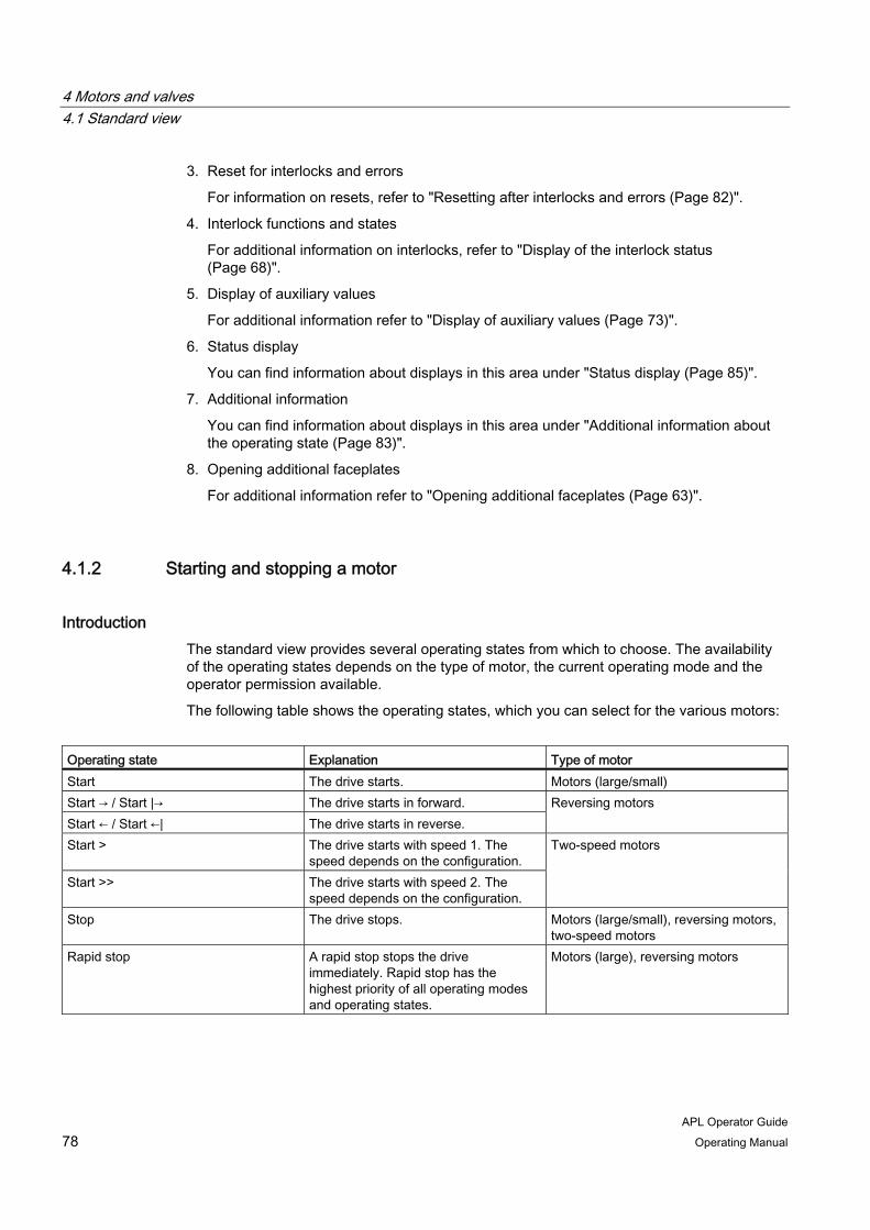
4 Motors and valves 4.1 Standard view
APL Operator Guide 78 Operating Manual
3. Reset for interlocks and errors
For information on resets, refer to "Resetting after interlocks and errors (Page 82)".
4. Interlock functions and states
For additional information on interlocks, refer to "Display of the interlock status (Page 68)".
5. Display of auxiliary values
For additional information refer to "Display of auxiliary values (Page 73)".
6. Status display
You can find information about displays in this area under "Status display (Page 85)".
7. Additional information
You can find information about displays in this area under "Additional information about the operating state (Page 83)".
8. Opening additional faceplates
For additional information refer to "Opening additional faceplates (Page 63)".
4.1.2 Starting and stopping a motor
Introduction The standard view provides several operating states from which to choose. The availability of the operating states depends on the type of motor, the current operating mode and the operator permission available.
The following table shows the operating states, which you can select for the various motors:
Operating state Explanation Type of motor Start The drive starts. Motors (large/small) Start → / Start |→ The drive starts in forward. Start ← / Start ←| The drive starts in reverse.
Reversing motors
Start > The drive starts with speed 1. The speed depends on the configuration.
Start >> The drive starts with speed 2. The speed depends on the configuration.
Two-speed motors
Stop The drive stops. Motors (large/small), reversing motors, two-speed motors
Rapid stop A rapid stop stops the drive immediately. Rapid stop has the highest priority of all operating modes and operating states.
Motors (large), reversing motors

4 Motors and valves 4.1 Standard view
APL Operator Guide Operating Manual 79
Requirement You have the required operator permission.
For additional information refer to "Operator permission and enable (Page 29)".
Procedure To set the device to a new operating state, follow these steps:
1. Open the faceplate.
2. Click on the button to open the operating window.
The operating window is opened as an extension of the faceplate.
3. Click on the button for the desired operating state.
4. If acknowledgement is required, click "OK".

4 Motors and valves 4.1 Standard view
APL Operator Guide 80 Operating Manual
4.1.3 Opening and closing of valves
Introduction The standard view provides several operating states from which to choose. The availability of the operating states depends on the type of valve, the current operating mode and the operator permission available.
The following table shows the operating states, which you can select for the various valves:
Operating state Explanation Type of valve Open The valve opens. Valves (large/small), servo-valves Close The valve closes. Valves (large/small), servo-valve Position 1/2/3 (Designation of the individual positions is set during configuration.)
The valve is moved to a switch position or idle position. The switch position that the valve assumes when a position is selected depends on the configuration.
Two-way valve
Stop The drive stops. Motor valve Rapid stop A rapid stop stops the drive
immediately. Rapid stop has the highest priority of all operating modes and operating states.
Motor valve
Requirement You have the required operator permissions.
For additional information refer to "Operator permission and enable (Page 29)".
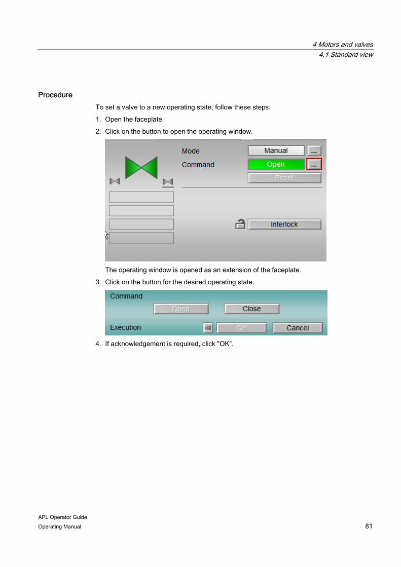
4 Motors and valves 4.1 Standard view
APL Operator Guide Operating Manual 81
Procedure To set a valve to a new operating state, follow these steps:
1. Open the faceplate.
2. Click on the button to open the operating window.
The operating window is opened as an extension of the faceplate.
3. Click on the button for the desired operating state.
4. If acknowledgement is required, click "OK".
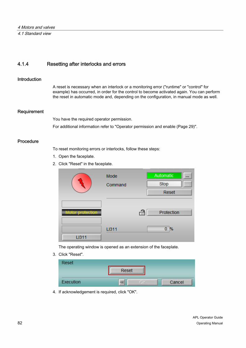
4 Motors and valves 4.1 Standard view
APL Operator Guide 82 Operating Manual
4.1.4 Resetting after interlocks and errors
Introduction A reset is necessary when an interlock or a monitoring error ("runtime" or "control" for example) has occurred, in order for the control to become activated again. You can perform the reset in automatic mode and, depending on the configuration, in manual mode as well.
Requirement You have the required operator permission.
For additional information refer to "Operator permission and enable (Page 29)".
Procedure To reset monitoring errors or interlocks, follow these steps:
1. Open the faceplate.
2. Click "Reset" in the faceplate.
The operating window is opened as an extension of the faceplate.
3. Click "Reset".
4. If acknowledgement is required, click "OK".
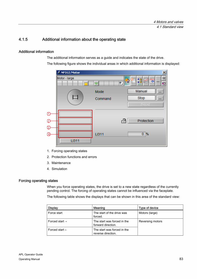
4 Motors and valves 4.1 Standard view
APL Operator Guide Operating Manual 83
4.1.5 Additional information about the operating state
Additional information The additional information serves as a guide and indicates the state of the drive.
The following figure shows the individual areas in which additional information is displayed:
1. Forcing operating states
2. Protection functions and errors
3. Maintenance
4. Simulation
Forcing operating states When you force operating states, the drive is set to a new state regardless of the currently pending control. The forcing of operating states cannot be influenced via the faceplate.
The following table shows the displays that can be shown in this area of the standard view:
Display Meaning Type of device Force start The start of the drive was
forced. Motors (large)
Forced start → The start was forced in the forward direction.
Forced start ← The start was forced in the reverse direction.
Reversing motors

4 Motors and valves 4.1 Standard view
APL Operator Guide 84 Operating Manual
Display Meaning Type of device Forced start > The start was forced with speed
1. The speed depends on the configuration.
Forced start >> The start was forced with speed 2. The speed depends on the configuration.
Two-speed motors
Forced stop The stop of the drive was forced.
Motors (large), reversing motors, two-speed motors, motor valves
Forced open The opening of the valve was forced.
Forced close The closing of the valve was forced.
Standard valves (large)
Forced Pos0/Pos1/Pos2 The valve is forced to a switch position or neutral position.
Two-way valve
Forced tracking Forced tracking of the manipulated variable was forced. Forced tracking allows the controller output of a higher-level controller to be set to a value that can be specified.
Tracking Tracking of a manipulated variable was forced. Tracking enables bumpless changeover for controllers.
Servo-valve
Request 0/1 A reset of the device is expected.
Motors and valves (APL)
Protection functions and errors The following information can be displayed depending on the state of the process tag.
● Motor protection
"Motor protection" is displayed when the motor is shut down by the motor protection function. The motor protection function is activated by thermal overload.
● Runtime error
"Runtime error" is displayed when the monitoring time is exceeded for the operating of motors or for maintaining a position for valves. The monitoring time specifies the period in which the feedback value can briefly change its value without triggering an error message. If the value change last more than the specified monitoring time, an error message is generated and the device moves to its neutral position.
● Control error
"Control error" is displayed when no feedback value is received for the control signal within a configured time period (monitoring time). In this case, the drive moves to its neutral position, depending on the configuration, and an error message is generated.

4 Motors and valves 4.1 Standard view
APL Operator Guide Operating Manual 85
● Invalid signal
"Invalid signal" is displayed when invalid combinations of related input signals occur. A valve cannot receive the close and open commands simultaneously, for example.
● Changeover error
"Changeover error" appears when an unintentional drive state occurs with a changeover from manual to automatic mode or from local to automatic mode. Bumpless changeover can be enabled or disabled for the configuration.
Maintenance For additional information on release for maintenance refer to "Activate or deactivate release for maintenance (Page 61)".
Simulation For additional information on simulation refer to "Activate or deactivate simulation (Page 60)".
4.1.6 Status display
Introduction The status display shows the status of a motor or valve in graphical form. Depending on the type of device, various icons are used to represent the specific features of the devices.
Status displays for motors The table below shows the icons that represent the motor states:
Icon State Motor type
Motor started (icon changes) Motors (large/small)
Motors (large/small)
Reversing motors
Variable-speed reversing motors
The motor is running
Two-speed motors

4 Motors and valves 4.1 Standard view
APL Operator Guide 86 Operating Manual
Icon State Motor type
Motor stopped (icon changes)
Motor idle
Error at motor (monitoring error, motor protection)
Motors (large/small), (variable-speed) reversing motors, two-speed motors
Motor out of service Motors (large), (variable-speed) reversing motors, two-speed motors
Status displays for valves The table below shows the icons that represent the valve states:
Icon State Valve type
Valves (large/small), servo-valves
Two-way valve
Valve is opening
Motor valve
Valves (large/small)
Two-way valve
Valve open
Motor valve
Valves (large/small), servo-valves
Two-way valve
Valve is closing
Motor valve
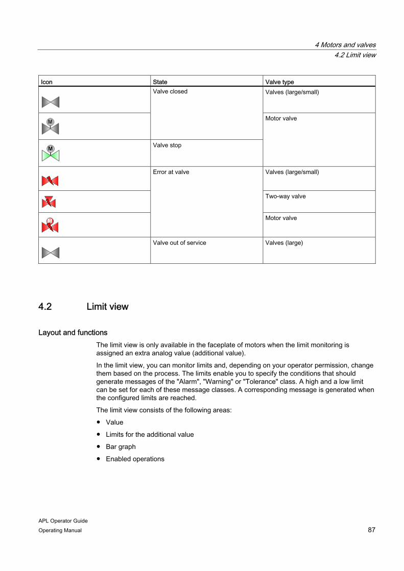
4 Motors and valves 4.2 Limit view
APL Operator Guide Operating Manual 87
Icon State Valve type
Valves (large/small)
Valve closed
Valve stop
Motor valve
Valves (large/small)
Two-way valve
Error at valve
Motor valve
Valve out of service Valves (large)
4.2 Limit view
Layout and functions The limit view is only available in the faceplate of motors when the limit monitoring is assigned an extra analog value (additional value).
In the limit view, you can monitor limits and, depending on your operator permission, change them based on the process. The limits enable you to specify the conditions that should generate messages of the "Alarm", "Warning" or "Tolerance" class. A high and a low limit can be set for each of these message classes. A corresponding message is generated when the configured limits are reached.
The limit view consists of the following areas:
● Value
● Limits for the additional value
● Bar graph
● Enabled operations

4 Motors and valves 4.2 Limit view
APL Operator Guide 88 Operating Manual
Value
This area shows the current value with the corresponding signal status and scale range for the bar graph. The scale range of the bar graph is predetermined and cannot be edited in the faceplate.
Limits for the additional value
The limits of the additional value are displayed in this area. The following table shows the limits that you can change based on the process with the proper operator permission:
Limit Explanation H alarm High limit for triggering a message of "Alarm"
class H warning High limit for triggering a message of "Warning"
class H tolerance High limit for triggering a message of "Tolerance"
class Hysteresis You can configure a hysteresis for the limits, for
example, to suppress signal flutter. L tolerance Low limit for triggering a message of "Alarm"
class L warning Low limit for triggering a message of "Warning"
class L alarm Low limit for triggering a message of "Tolerance"
class
You can find additional information on changing values in the faceplate under "Change values (Page 53)".
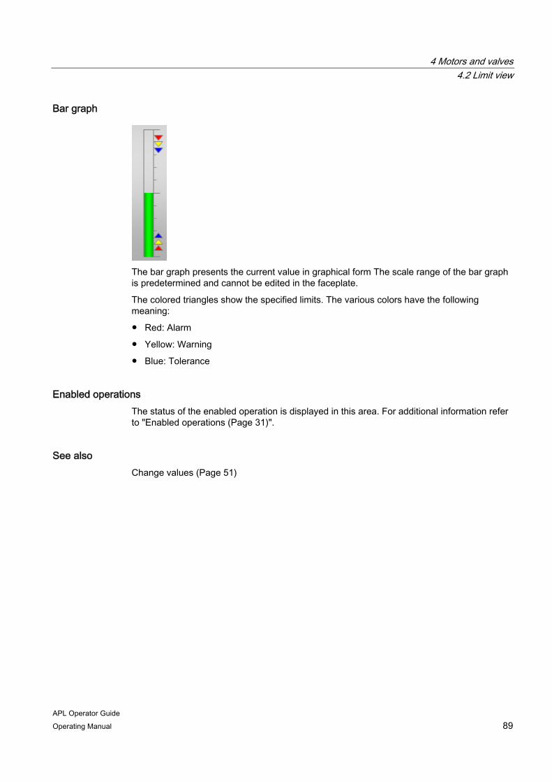
4 Motors and valves 4.2 Limit view
APL Operator Guide Operating Manual 89
Bar graph
The bar graph presents the current value in graphical form The scale range of the bar graph is predetermined and cannot be edited in the faceplate.
The colored triangles show the specified limits. The various colors have the following meaning:
● Red: Alarm
● Yellow: Warning
● Blue: Tolerance
Enabled operations The status of the enabled operation is displayed in this area. For additional information refer to "Enabled operations (Page 31)".
See also Change values (Page 51)
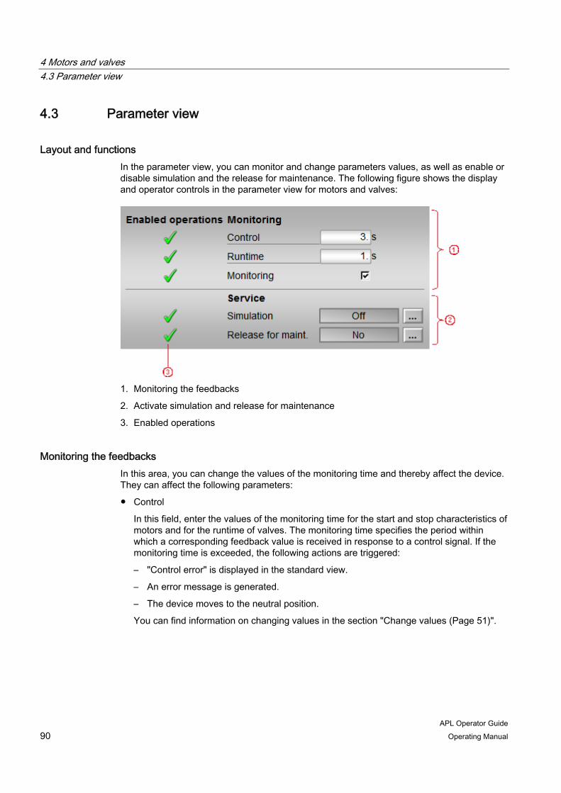
4 Motors and valves 4.3 Parameter view
APL Operator Guide 90 Operating Manual
4.3 Parameter view
Layout and functions In the parameter view, you can monitor and change parameters values, as well as enable or disable simulation and the release for maintenance. The following figure shows the display and operator controls in the parameter view for motors and valves:
1. Monitoring the feedbacks
2. Activate simulation and release for maintenance
3. Enabled operations
Monitoring the feedbacks In this area, you can change the values of the monitoring time and thereby affect the device. They can affect the following parameters:
● Control
In this field, enter the values of the monitoring time for the start and stop characteristics of motors and for the runtime of valves. The monitoring time specifies the period within which a corresponding feedback value is received in response to a control signal. If the monitoring time is exceeded, the following actions are triggered:
– "Control error" is displayed in the standard view.
– An error message is generated.
– The device moves to the neutral position.
You can find information on changing values in the section "Change values (Page 51)".

4 Motors and valves 4.3 Parameter view
APL Operator Guide Operating Manual 91
● Runtime
In this field, enter the values of the monitoring time for the operating characteristics of motors and for maintaining the position of valves. The monitoring time specifies the period in which the feedback value can briefly change its value without triggering an error message. If the monitoring time is exceeded, the following actions are triggered:
– "Runtime error" is displayed in the standard view.
– An error message is generated.
– The device moves to the neutral position.
You can find information on changing values in the section "Change values (Page 51)".
● Monitoring
You can use the check box to enable monitoring of feedback (checked) or disable it (cleared). Static and dynamic errors are reset by disabling the monitoring. If you re-enable monitoring during ongoing operation of the plant, only dynamic monitoring will be performed.
Simulation and release for maintenance The status of the following functions is displayed in this area:
● Simulation
For additional information on simulation refer to "Activate or deactivate simulation (Page 60)".
● Release for maintenance
For additional information on simulation refer to "Activate or deactivate release for maintenance (Page 61)".
If you have the appropriate operator permissions, you can edit the settings in this area.
Enabled operations The status of the enabled operation is displayed in this area. For additional information refer to "Enabled operations (Page 31)".

4 Motors and valves 4.4 Preview
APL Operator Guide 92 Operating Manual
4.4 Preview
Layout and functions The preview displays information about the operability of the parameters in the entire faceplate. You cannot edit the values displayed in the preview.
The preview consists of the following areas:
● Automatic preview
● Enabled operations
● Inputs and outputs
Automatic preview Automatic preview shows the state in which the drive is set after a change from manual to automatic mode.
If the motor is already in automatic mode, the current operating state is displayed in this area.
Enabled operations Information about the feasibility of the following actions is displayed in this area:
Action Explanation Start / Open Start motor / Open valve Stop / Close Stop motor / Close valve Reset Reset for interlocks and errors Automatic Switch to automatic mode Manual Switch to manual mode Local Switch to local mode Out of service Switch to "Out of service" operating mode Local operator permission Whether or not the device is released for
operation generally depends on this permission. The local operator permission can be set individually for each device. Devices at a work place can be released or locked independent of each other.
You can find additional information about enabled operations under "Operator permission and enable (Page 29)".
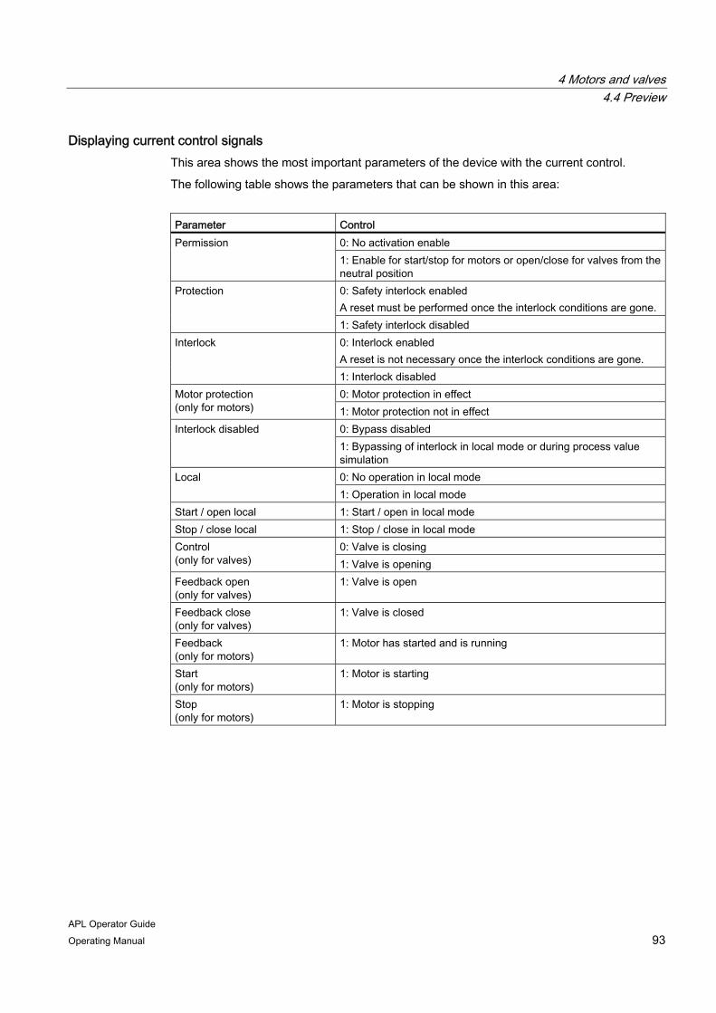
4 Motors and valves 4.4 Preview
APL Operator Guide Operating Manual 93
Displaying current control signals This area shows the most important parameters of the device with the current control.
The following table shows the parameters that can be shown in this area:
Parameter Control
0: No activation enable Permission 1: Enable for start/stop for motors or open/close for valves from the neutral position 0: Safety interlock enabled A reset must be performed once the interlock conditions are gone.
Protection
1: Safety interlock disabled 0: Interlock enabled A reset is not necessary once the interlock conditions are gone.
Interlock
1: Interlock disabled 0: Motor protection in effect Motor protection
(only for motors) 1: Motor protection not in effect 0: Bypass disabled Interlock disabled 1: Bypassing of interlock in local mode or during process value simulation 0: No operation in local mode Local 1: Operation in local mode
Start / open local 1: Start / open in local mode Stop / close local 1: Stop / close in local mode
0: Valve is closing Control (only for valves) 1: Valve is opening Feedback open (only for valves)
1: Valve is open
Feedback close (only for valves)
1: Valve is closed
Feedback (only for motors)
1: Motor has started and is running
Start (only for motors)
1: Motor is starting
Stop (only for motors)
1: Motor is stopping

4 Motors and valves 4.5 Additional views
APL Operator Guide 94 Operating Manual
4.5 Additional views
Additional views of the faceplates for motors and valves The faceplates of motors and valves also provide the following views:
● Alarm view (Page 37)
● Trend view (Page 41)
● Memo view (Page 45)
● Batch view (Page 47)
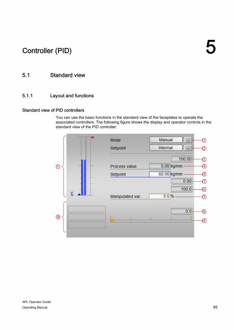
APL Operator Guide Operating Manual 95
Controller (PID) 55.1 Standard view
5.1.1 Layout and functions
Standard view of PID controllers You can use the basic functions in the standard view of the faceplates to operate the associated controllers. The following figure shows the display and operator controls in the standard view of the PID controller:

5 Controller (PID) 5.1 Standard view
APL Operator Guide 96 Operating Manual
1. Operating mode
For PID controllers, you can switch between the following operating modes:
– Manual mode
– Automatic mode
– Program mode
– Out of service
For additional information on the operating modes, refer to "Switching operating modes (Page 47)".
2. Setpoint specification
You can find information on changing the setpoint under "Switch setpoint specification (Page 56)".
3. High and low scale value of the process value
The scale range provides information about the display area of the bar graph (9). The values of the scale range cannot be edited in the faceplate.
4. Current process value
You can find information on simulation of the process value under "Simulate process value (Page 97)".
5. Current setpoint
You can find information on changing the setpoint under "Change setpoint (Page 98)".
6. High and low scale value of the setpoint
The scale range provides information about the display area of the bar graph (9). The values of the scale range cannot be edited in the faceplate.
7. Current manipulated variable
You can find information on changing the setpoint under "Change manipulated variable (Page 100)".
8. Bar graph for the manipulated variable
The current manipulated variable is shown as a bar display in this area. The visible area of the bar graph depends on the configuration.
9. Bar graph
You can find information on the bar graph under "Bar graph (Page 104)".
10. Additional information
You can find information about displays in this area under "Additional information about the operating state (Page 102)".
The standard view of the faceplate may also contain the following display and operator controls:
● Current feedback of the manipulated variable and the corresponding signal status
● Bar graph for position feedback

5 Controller (PID) 5.1 Standard view
APL Operator Guide Operating Manual 97
● Button for the standard view of the faceplate for the monitoring a control performance
● Button for the standard view of another faceplate
5.1.2 Simulate process value
Introduction In the faceplate, you can simulate the process value of the controller, for example, for testing or maintenance purposes.
Requirement ● Simulation is activated. You can recognized this by the following displays:
– In the block icon and faceplate
– In the standard view of the faceplate
You can find additional information on activating simulation via the faceplate under "Activate or deactivate simulation (Page 60)".
● You have the required operator permissions.
For additional information refer to "Operator permission and enable (Page 29)".
Procedure To simulate a process value, follow these steps:
1. Open the faceplate.
2. Click on the input box of the process value.
The operating window is opened as an extension of the faceplate.
3. Enter a value.
You can find additional information on changing values in the operating window under "Change values (Page 53)".
4. If acknowledgement is required, click "OK".

5 Controller (PID) 5.1 Standard view
APL Operator Guide 98 Operating Manual
5.1.3 Change setpoint
Introduction You can affect the manipulated variable of the controller by changing the setpoint. You can change the setpoint in manual or automatic mode. The changeover from manual to automatic mode can be bumpless, depending on the configuration. With bumpless changeover, the setpoint is tracked to the process value in manual mode. After switching to automatic mode, the manipulated variable remains constant until the setpoint value is changed or the process value changes. If the setpoint is not tracked, the manipulated variable is recalculated immediately after switching to automatic mode.
The enable or disable bumpless changeover in the parameter in view of the faceplate.
Requirement ● The controller is in manual or automatic mode.
● The setpoint is specified internally.
● You have the required operator permissions.
For additional information refer to "Operator permission and enable (Page 29)".
Procedure To change the setpoint, follow these steps:
1. Open the faceplate.
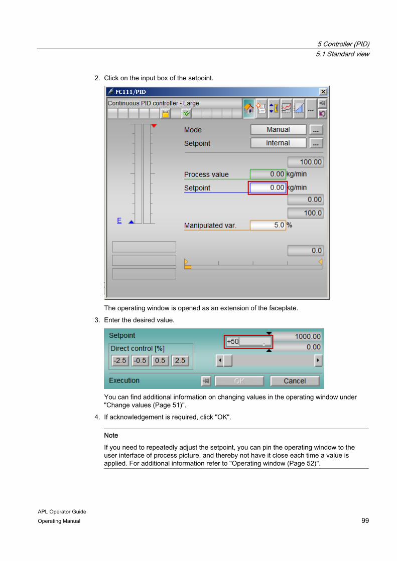
5 Controller (PID) 5.1 Standard view
APL Operator Guide Operating Manual 99
2. Click on the input box of the setpoint.
The operating window is opened as an extension of the faceplate.
3. Enter the desired value.
You can find additional information on changing values in the operating window under "Change values (Page 51)".
4. If acknowledgement is required, click "OK".
Note
If you need to repeatedly adjust the setpoint, you can pin the operating window to the user interface of process picture, and thereby not have it close each time a value is applied. For additional information refer to "Operating window (Page 52)".

5 Controller (PID) 5.1 Standard view
APL Operator Guide 100 Operating Manual
5.1.4 Change manipulated variable
Introduction You can change the manipulated variable (output signal) of a controller manually in manual mode. The manipulated variable can be analog or binary here.
In automatic mode, the manipulated variable is calculated automatically and can be simulated.
Requirement ● The controller is in manual mode.
● You have the required operator permissions.
For additional information refer to "Operator permission and enable (Page 29)".
Procedure To change the manipulated variable, follow these steps:
1. Open the faceplate.
2. Click on the input box of the manipulated variable.
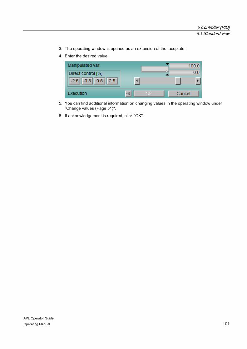
5 Controller (PID) 5.1 Standard view
APL Operator Guide Operating Manual 101
3. The operating window is opened as an extension of the faceplate.
4. Enter the desired value.
5. You can find additional information on changing values in the operating window under
"Change values (Page 51)".
6. If acknowledgement is required, click "OK".

5 Controller (PID) 5.1 Standard view
APL Operator Guide 102 Operating Manual
5.1.5 Additional information about the operating state
Additional information The additional information serves as a guide and indicates the state of the PID controller.
The following figure shows the individual areas in which additional information is displayed:
1. Optimizing and tracking
2. Simulation
3. Maintenance
5 Controller (PID) 5.1 Standard view
APL Operator Guide Operating Manual 103
Optimizing and tracking The following displays appear in this area:
● Optimizing
"Optimizing" is displayed when the controller tuning is enabled via the parameter view of the faceplate.
● Tracking
The manipulated variable is tracked to enable bumpless changeover of controllers. Tracking is set during configuration and displayed in the standard view of the faceplate as "Tracking" additional information.
Manual mode takes priority over tracking to enable the controller to be set to manual mode continue normal operation after tracking the manipulated variable .
● Forced tracking
Forced tracking is used to set the controller output to a value specified by a higher-level controller. This function is set during configuration and displayed in the standard view of the faceplate as "Forced tracking" additional information.
You cannot switch to manual mode from the faceplate with forced tracking. The manipulated variable cannot be limited.
Simulation For additional information on simulation refer to "Activate or deactivate simulation (Page 60)".
Maintenance For additional information on release for maintenance refer to "Activate or deactivate release for maintenance (Page 61)".
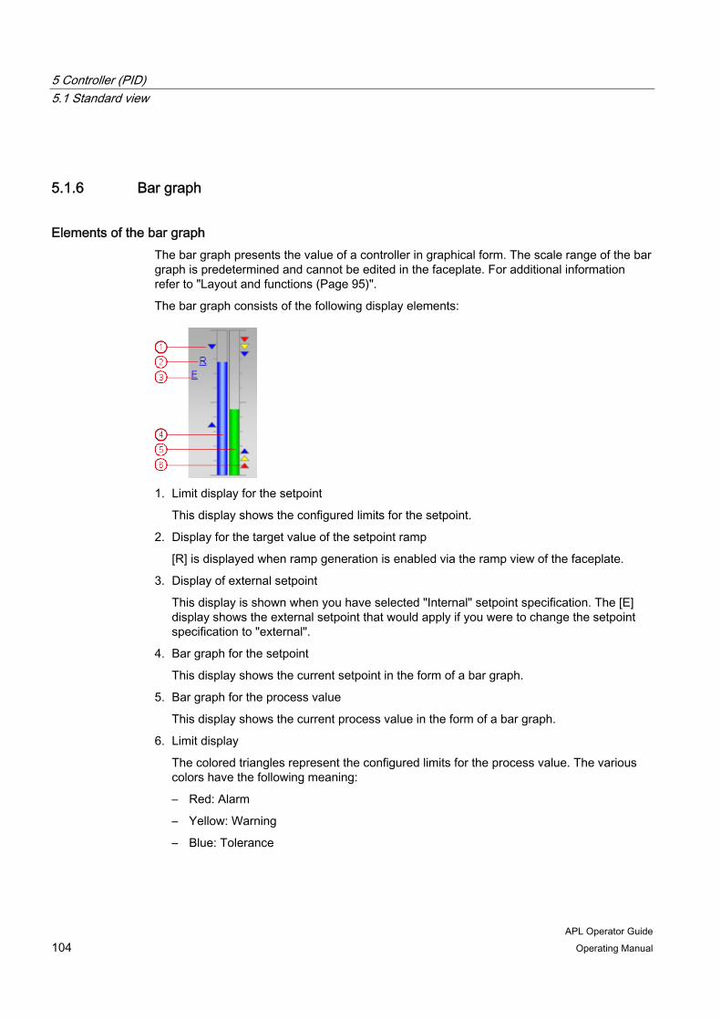
5 Controller (PID) 5.1 Standard view
APL Operator Guide 104 Operating Manual
5.1.6 Bar graph
Elements of the bar graph The bar graph presents the value of a controller in graphical form. The scale range of the bar graph is predetermined and cannot be edited in the faceplate. For additional information refer to "Layout and functions (Page 95)".
The bar graph consists of the following display elements:
1. Limit display for the setpoint
This display shows the configured limits for the setpoint.
2. Display for the target value of the setpoint ramp
[R] is displayed when ramp generation is enabled via the ramp view of the faceplate.
3. Display of external setpoint
This display is shown when you have selected "Internal" setpoint specification. The [E] display shows the external setpoint that would apply if you were to change the setpoint specification to "external".
4. Bar graph for the setpoint
This display shows the current setpoint in the form of a bar graph.
5. Bar graph for the process value
This display shows the current process value in the form of a bar graph.
6. Limit display
The colored triangles represent the configured limits for the process value. The various colors have the following meaning:
– Red: Alarm
– Yellow: Warning
– Blue: Tolerance
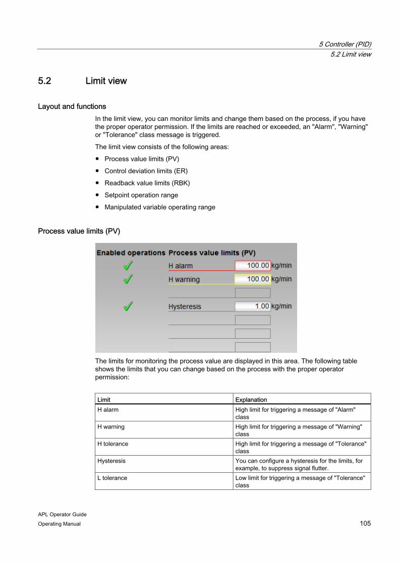
5 Controller (PID) 5.2 Limit view
APL Operator Guide Operating Manual 105
5.2 Limit view
Layout and functions In the limit view, you can monitor limits and change them based on the process, if you have the proper operator permission. If the limits are reached or exceeded, an "Alarm", "Warning" or "Tolerance" class message is triggered.
The limit view consists of the following areas:
● Process value limits (PV)
● Control deviation limits (ER)
● Readback value limits (RBK)
● Setpoint operation range
● Manipulated variable operating range
Process value limits (PV)
The limits for monitoring the process value are displayed in this area. The following table shows the limits that you can change based on the process with the proper operator permission:
Limit Explanation H alarm High limit for triggering a message of "Alarm"
class H warning High limit for triggering a message of "Warning"
class H tolerance High limit for triggering a message of "Tolerance"
class Hysteresis You can configure a hysteresis for the limits, for
example, to suppress signal flutter. L tolerance Low limit for triggering a message of "Tolerance"
class
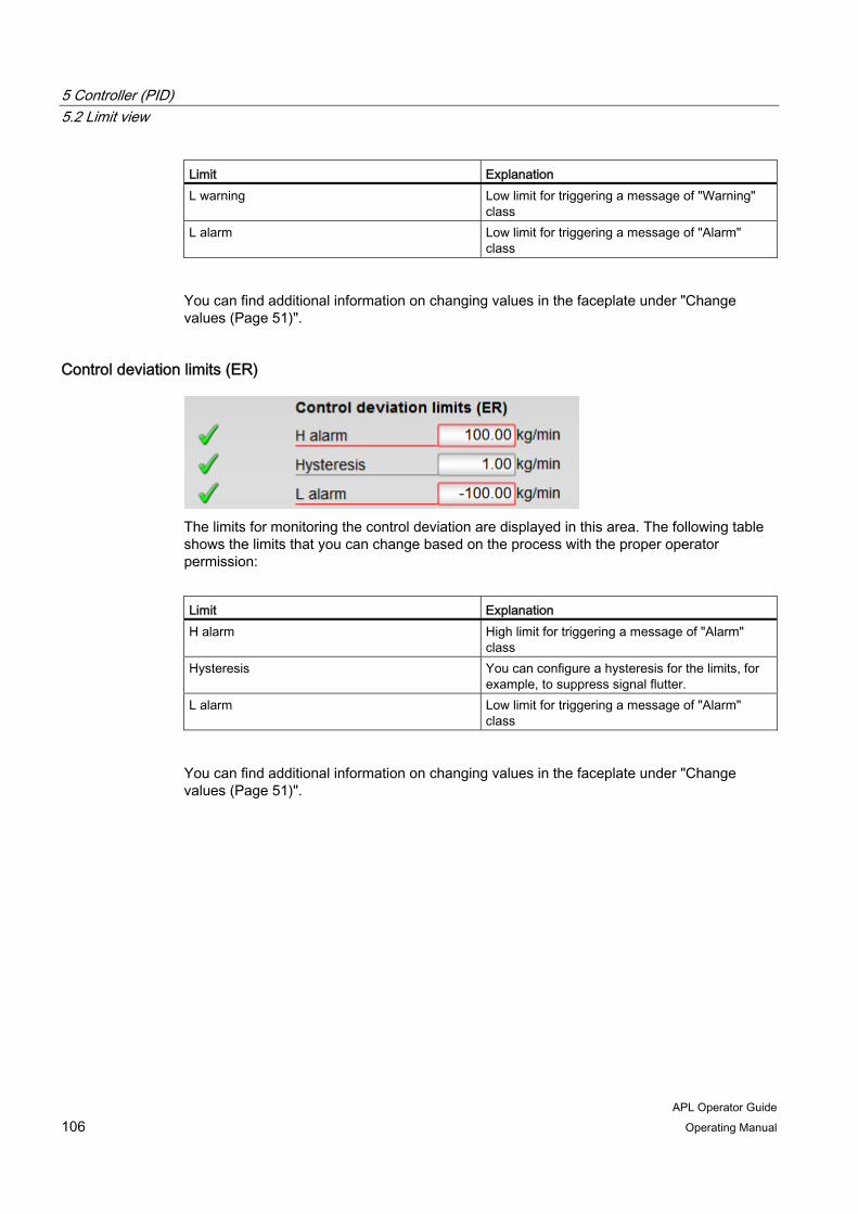
5 Controller (PID) 5.2 Limit view
APL Operator Guide 106 Operating Manual
Limit Explanation L warning Low limit for triggering a message of "Warning"
class L alarm Low limit for triggering a message of "Alarm"
class
You can find additional information on changing values in the faceplate under "Change values (Page 51)".
Control deviation limits (ER)
The limits for monitoring the control deviation are displayed in this area. The following table shows the limits that you can change based on the process with the proper operator permission:
Limit Explanation H alarm High limit for triggering a message of "Alarm"
class Hysteresis You can configure a hysteresis for the limits, for
example, to suppress signal flutter. L alarm Low limit for triggering a message of "Alarm"
class
You can find additional information on changing values in the faceplate under "Change values (Page 51)".

5 Controller (PID) 5.2 Limit view
APL Operator Guide Operating Manual 107
Readback value limits (RBK)
The limits for monitoring the readback value are displayed in this area. The following table shows the limits that you can change based on the process with the proper operator permission:
Limit Explanation H warning High limit for triggering a message of "Warning"
class Hysteresis You can configure a hysteresis for the limits, for
example, to suppress signal flutter. L warning Low limit for triggering a message of "Warning"
class
You can find additional information on changing values in the faceplate under "Change values (Page 51)".
Setpoint operation range
The operating range of the setpoint is displayed in this area. The following table shows the limits that you can change based on the process with the proper operator permission:
Limit Explanation H range High range limit L range Low range limit
You can find additional information on changing values in the faceplate under "Change values (Page 51)".

5 Controller (PID) 5.3 Parameter view
APL Operator Guide 108 Operating Manual
Manipulated variable operating range
The operating range of the manipulated variable is displayed in this area. The following table shows the limits that you can change based on the process with the proper operator permission:
Limit Explanation H range High range limit L range Low range limit
You can find additional information on changing values in the faceplate under "Change values (Page 51)".
Enabled operations The status of the enabled operation is displayed in this area. For additional information refer to "Enabled operations (Page 31)".
5.3 Parameter view
Layout and functions In the parameter view, you can monitor and change parameters values, as well as enable or disable simulation and the release for maintenance.
The parameter view consists of the following areas:
● Settings for controller tuning and bumpless changeover
● Parameter
● Service
● Enabled operations

5 Controller (PID) 5.3 Parameter view
APL Operator Guide Operating Manual 109
Settings for bumpless changeover
You can make the following settings in this area:
● PID optimization
You can use this check box to allow a measurement or control engineer to optimize the control parameters of the controller (checked) or reset the enable (cleared). The confirmation of each change of state is made in the operating window.
● SP := PV in manual mode
You can use the check box to enable bumpless changeover from manual to automatic mode (checked) or disable it (cleared). The confirmation of each change of state is made in the operating window.
With bumpless changeover, the setpoint is tracked to the process value in manual mode. After switching to automatic mode, the manipulated variable remains constant until the setpoint value is changed or the process value changes. If the setpoint is not tracked, the manipulated variable is recalculated immediately after switching to automatic mode.
● SP := SP external
You can use the check box to enable bumpless changeover of the setpoint specification from "internal" to "external" (checked) or disable it (cleared). The confirmation of each change of state is made in the operating window.
With bumpless changeover of the setpoint specification, the internal setpoint is tracked to the external setpoint.

5 Controller (PID) 5.3 Parameter view
APL Operator Guide 110 Operating Manual
Parameter values
In this area. you can monitor the values of the following parameters and edit them, if you have the proper operator permission:
Parameter Explanation Gain Proportional gain Integral time Integral time in seconds [s] Derivative time TD Derivative time in seconds [s] Derivative gain Gain of the derivative action Dead band Width of dead band Control zone Width of control zone Motor actuating time Motor pitch in seconds [s] Minimum pulse duration Minimum pulse duration in seconds [s] Minimum pause Minimum break duration in seconds [s]
The availability of the parameters depends on the configuration.
Service The status of the following functions is displayed in this area:
● Simulation
For additional information on simulation refer to "Activate or deactivate simulation (Page 60)".
● Release for maintenance
For additional information on release for maintenance refer to "Activate or deactivate release for maintenance (Page 61)".
If you have the appropriate operator permissions, you can edit the settings in this area.
Enabled operations The status of the enabled operation is displayed in this area. For additional information refer to "Enabled operations (Page 31)".

5 Controller (PID) 5.4 Ramp view
APL Operator Guide Operating Manual 111
5.4 Ramp view
Layout and functions Starting at the current internal setpoint, the setpoint can approach a target setpoint in the form of a ramp. You control this ramp mode in the ramp view.
The following figure shows the areas of the ramp view:
1. Gradient limit activated
2. Settings for the ramp mode
3. Activating the ramp mode
4. Enabled operations
Activating the gradient limit You can use the "Gradient limits on" check box to activate the gradient limit of the setpoint (checked) or disable it (cleared). When you click the check box, the operating window opens and you can make the desired settings in it.

5 Controller (PID) 5.4 Ramp view
APL Operator Guide 112 Operating Manual
"Gradient limit" can be set separately for positive or negative setpoint changes:
● Gradient +
With this value you specify the limit for positive changes of the setpoint. You can change the value of the input box. The new value is entered in the operating window that opens as an extension of the faceplate when you click the input box.
You can find information on changing values under "Change values (Page 51)".
● Gradient -
With this value you specify the limit for negative changes of the setpoint. You can change the value of the input box. The new value is entered in the operating window that opens as an extension of the faceplate when you click the input box.
Settings for the ramp mode In this area, you can choose whether the setpoint ramp is specified via the duration or via the gradient.
● Specification via duration
The gradient of the setpoint is calculated automatically so that the setpoint will reach the target value after the configured duration. The duration starts with the start of the ramp mode. Once the target setpoint is reached, the ramp mode is automatically terminated.
● Specification via gradients
The ramp slope corresponds to the positive or negative rate of change set during configuration. Once the target setpoint is reached, the ramp mode is automatically terminated.
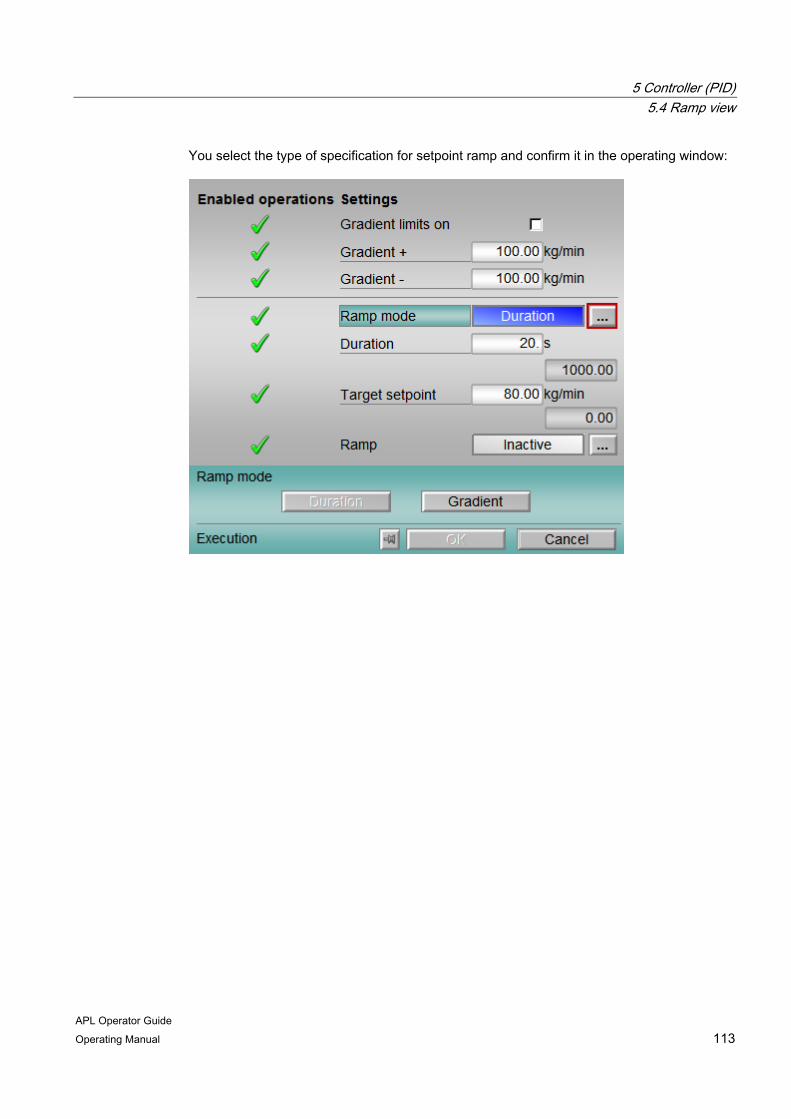
5 Controller (PID) 5.4 Ramp view
APL Operator Guide Operating Manual 113
You select the type of specification for setpoint ramp and confirm it in the operating window:

5 Controller (PID) 5.4 Ramp view
APL Operator Guide 114 Operating Manual
Activating the ramp mode The current status of the ramp mode is displayed in this area. You can change this status by opening the operating window of the faceplate and activating or deactivating the ramp mode.
Activation is only possible if the setpoint specification is performed internally and the gradient limitation is inactive. The activation of the ramp mode is valid for one setpoint change and is terminated again after the target setpoint is reached.
Enabled operations The status of the enabled operation is displayed in this area. For additional information refer to "Enabled operations (Page 31)".

5 Controller (PID) 5.5 Preview
APL Operator Guide Operating Manual 115
5.5 Preview
Layout and functions The preview displays information about the operability of the parameters in the entire faceplate. You cannot edit the values displayed in the preview.
The preview consists of the following areas:
● Values preview
● Enabled operations
Values preview This area provides you a preview of certain parameter values.
The following table shows the parameters that can be shown in this area:
Parameter Explanation SP external Currently applicable external setpoint SP internal Currently applicable internal setpoint Control deviation Current control deviation Program value Specified value for program mode Disturbance Additive value for feedforward control
1: Tracking of manipulated variable active Track MV 0: Tracking of manipulated variable not active
Tracking value Effective manipulated variable with tracking (Track MV = 1).
Enabled operations Information about the feasibility of the following actions is displayed in this area:
Action Explanation SP external Feedforward external setpoint SP internal Feedforward internal setpoint SP Change Change setpoint Change MV Change manipulated variable Program mode Switch to program mode Automatic Switch to automatic mode Manual Switch to manual mode
5 Controller (PID) 5.6 Additional views
APL Operator Guide 116 Operating Manual
Action Explanation Out of service Switch to "Out of service" operating mode Local operator permission Whether or not the device is released for
operation generally depends on this permission. The local operator permission can be set individually for each device. Devices at a work place can be released or locked independent of each other.
You can find additional information about enabled operations under "Operator permission and enable (Page 29)".
5.6 Additional views
Additional views of the faceplates for PID controllers The faceplates of PID controller also provide the following views:
● Alarm view (Page 37)
● Trend view (Page 41)
● Memo view (Page 45)
● Batch view (Page 47)
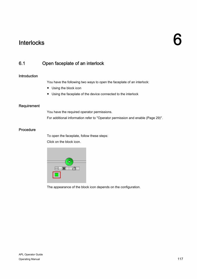
APL Operator Guide Operating Manual 117
Interlocks 66.1 Open faceplate of an interlock
Introduction You have the following two ways to open the faceplate of an interlock:
● Using the block icon
● Using the faceplate of the device connected to the interlock
Requirement You have the required operator permissions.
For additional information refer to "Operator permission and enable (Page 29)".
Procedure To open the faceplate, follow these steps:
Click on the block icon.
The appearance of the block icon depends on the configuration.

6 Interlocks 6.2 Standard view
APL Operator Guide 118 Operating Manual
Or click on the button of a configured interlock.
6.2 Standard view
Layout and functions The interlocks evaluate input signals based on a binary logic (AND, OR), and forward the result as an output signal to the connected device. With an output signal of "1", the interlock condition is not fulfilled and the connected device is not interlocked. With an output signal of "0", the interlock condition is fulfilled and the connected device is moved to the safety position. A restart of the device in this case is only possible when the interlock conditions are no longer fulfilled and the output signal switches from "0" to "1". It may also be necessary to reset the device, depending on the interlock function.
You can find information on the interlock functions and states under "Display of the interlock status (Page 68)".

6 Interlocks 6.2 Standard view
APL Operator Guide Operating Manual 119
The standard view of the faceplates provides you with information about the status of input and output signals and gives you the opportunity to influence them and to navigate to the faceplates of the interconnected devices. The following figure shows the operating and display elements in the standard view for interlocks:
1. Display of the interlock status
2. Status for initial signal acquisition
3. Opening the faceplate of the output signal
For additional information refer to "Opening the faceplate of a connected value (Page 122)".
4. Status display of the output signal
5. Status display of signal processing
6. Resetting the settings of the signal processing
You can find information on resetting the settings under "Resetting settings (Page 126)".
7. Opening the faceplate of the input signal
You can find information on opening additional faceplates under "Opening the faceplate of a connected value (Page 122)".
8. Display of input values
9. Bypassing the input signal or resetting the bypass
For additional information refer to "Bypassing input signals (Page 125)".
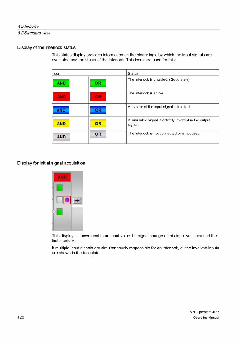
6 Interlocks 6.2 Standard view
APL Operator Guide 120 Operating Manual
Display of the interlock status This status display provides information on the binary logic by which the input signals are evaluated and the status of the interlock. This icons are used for this:
Icon Status
The interlock is disabled. (Good state)
The interlock is active.
A bypass of the input signal is in effect.
A simulated signal is actively involved in the output signal.
The interlock is not connected or is not used.
Display for initial signal acquisition
This display is shown next to an input value if a signal change of this input value caused the last interlock.
If multiple input signals are simultaneously responsible for an interlock, all the involved inputs are shown in the faceplate.
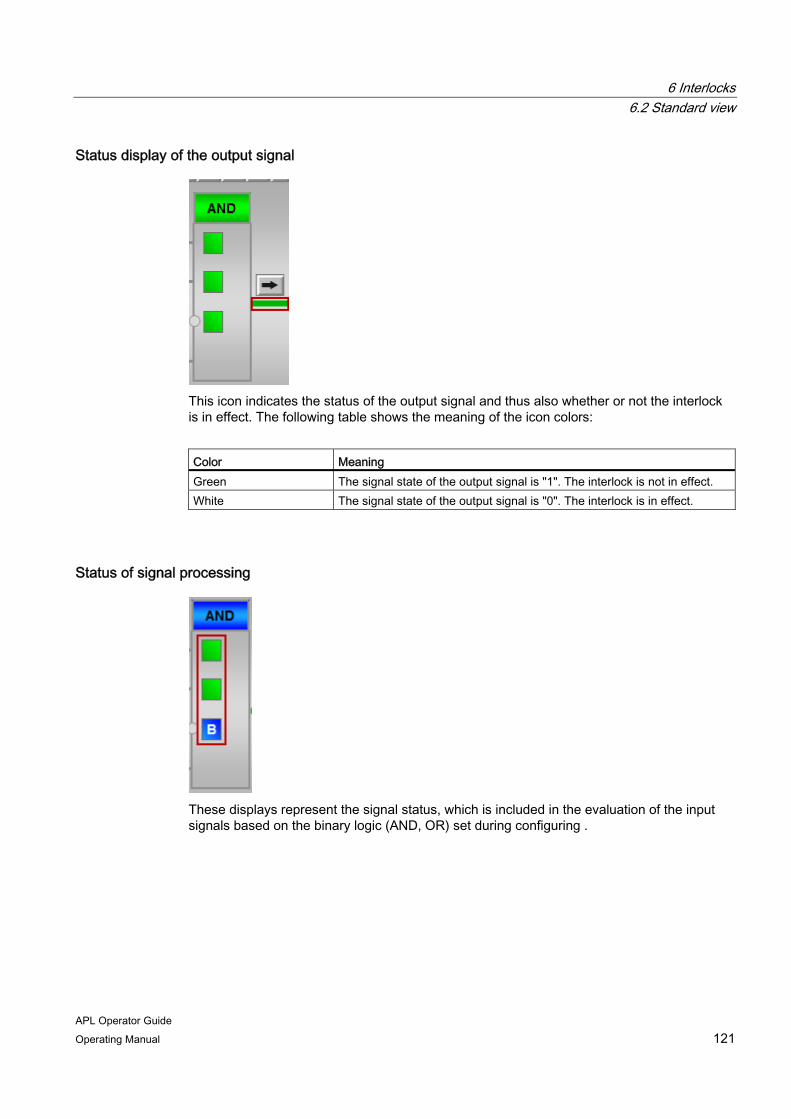
6 Interlocks 6.2 Standard view
APL Operator Guide Operating Manual 121
Status display of the output signal
This icon indicates the status of the output signal and thus also whether or not the interlock is in effect. The following table shows the meaning of the icon colors:
Color Meaning Green The signal state of the output signal is "1". The interlock is not in effect. White The signal state of the output signal is "0". The interlock is in effect.
Status of signal processing
These displays represent the signal status, which is included in the evaluation of the input signals based on the binary logic (AND, OR) set during configuring .
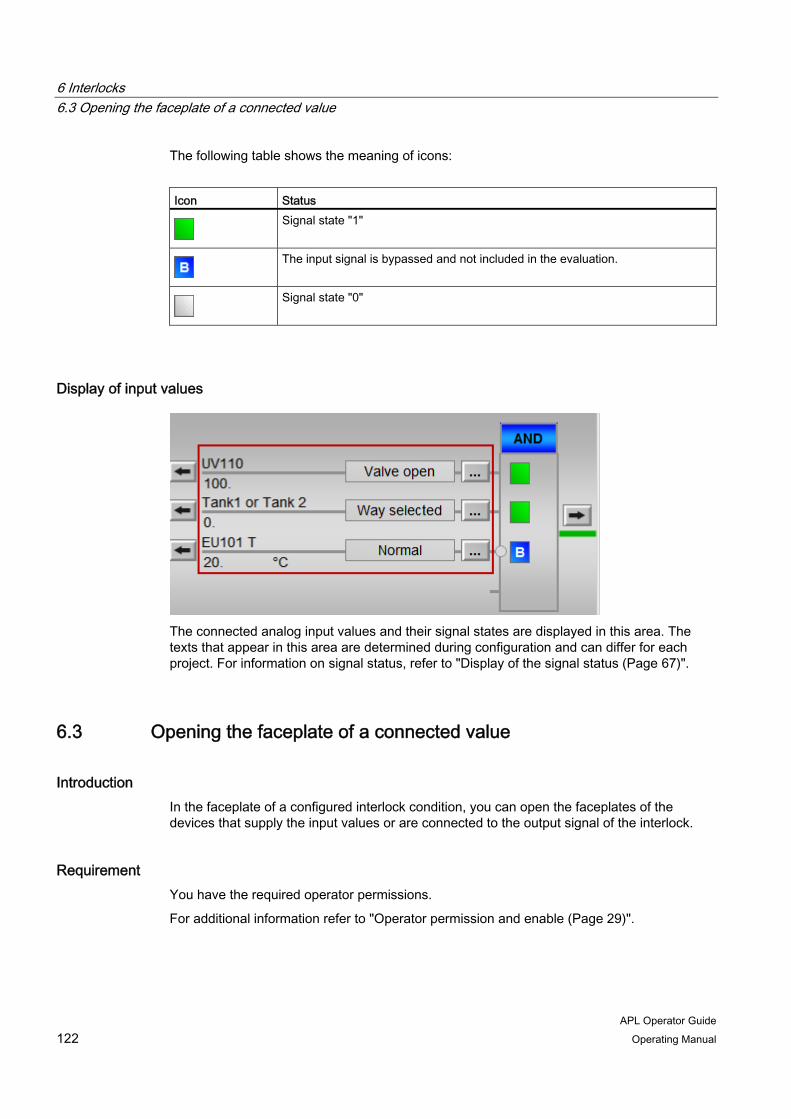
6 Interlocks 6.3 Opening the faceplate of a connected value
APL Operator Guide 122 Operating Manual
The following table shows the meaning of icons:
Icon Status
Signal state "1"
The input signal is bypassed and not included in the evaluation.
Signal state "0"
Display of input values
The connected analog input values and their signal states are displayed in this area. The texts that appear in this area are determined during configuration and can differ for each project. For information on signal status, refer to "Display of the signal status (Page 67)".
6.3 Opening the faceplate of a connected value
Introduction In the faceplate of a configured interlock condition, you can open the faceplates of the devices that supply the input values or are connected to the output signal of the interlock.
Requirement You have the required operator permissions.
For additional information refer to "Operator permission and enable (Page 29)".

6 Interlocks 6.3 Opening the faceplate of a connected value
APL Operator Guide Operating Manual 123
Opening the faceplate of an input value To open the faceplate of a device that supplies the input values, follow these steps:
1. Open the faceplate of the interlock.
2. Click the button to open the faceplate of the desired input value.
The faceplate of the input values opens.
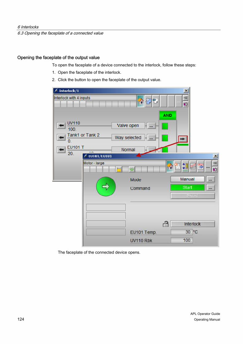
6 Interlocks 6.3 Opening the faceplate of a connected value
APL Operator Guide 124 Operating Manual
Opening the faceplate of the output value To open the faceplate of a device connected to the interlock, follow these steps:
1. Open the faceplate of the interlock.
2. Click the button to open the faceplate of the output value.
The faceplate of the connected device opens.
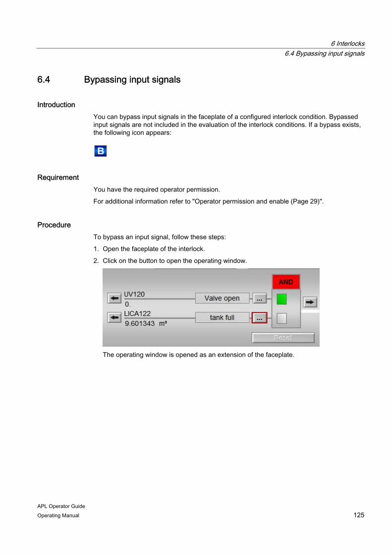
6 Interlocks 6.4 Bypassing input signals
APL Operator Guide Operating Manual 125
6.4 Bypassing input signals
Introduction You can bypass input signals in the faceplate of a configured interlock condition. Bypassed input signals are not included in the evaluation of the interlock conditions. If a bypass exists, the following icon appears:
Requirement You have the required operator permission.
For additional information refer to "Operator permission and enable (Page 29)".
Procedure To bypass an input signal, follow these steps:
1. Open the faceplate of the interlock.
2. Click on the button to open the operating window.
The operating window is opened as an extension of the faceplate.
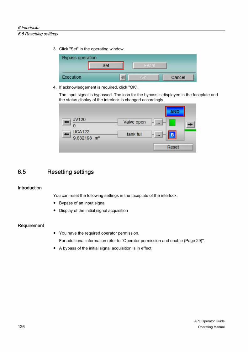
6 Interlocks 6.5 Resetting settings
APL Operator Guide 126 Operating Manual
3. Click "Set" in the operating window.
4. If acknowledgement is required, click "OK".
The input signal is bypassed. The icon for the bypass is displayed in the faceplate and the status display of the interlock is changed accordingly.
6.5 Resetting settings
Introduction You can reset the following settings in the faceplate of the interlock:
● Bypass of an input signal
● Display of the initial signal acquisition
Requirement ● You have the required operator permission.
For additional information refer to "Operator permission and enable (Page 29)".
● A bypass of the initial signal acquisition is in effect.
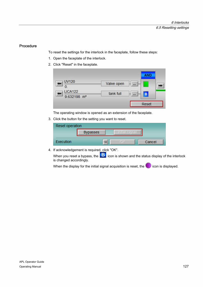
6 Interlocks 6.5 Resetting settings
APL Operator Guide Operating Manual 127
Procedure To reset the settings for the interlock in the faceplate, follow these steps:
1. Open the faceplate of the interlock.
2. Click "Reset" in the faceplate.
The operating window is opened as an extension of the faceplate.
3. Click the button for the setting you want to reset.
4. If acknowledgement is required, click "OK".
When you reset a bypass, the icon is shown and the status display of the interlock is changed accordingly.
When the display for the initial signal acquisition is reset, the icon is displayed.

6 Interlocks 6.5 Resetting settings
APL Operator Guide 128 Operating Manual
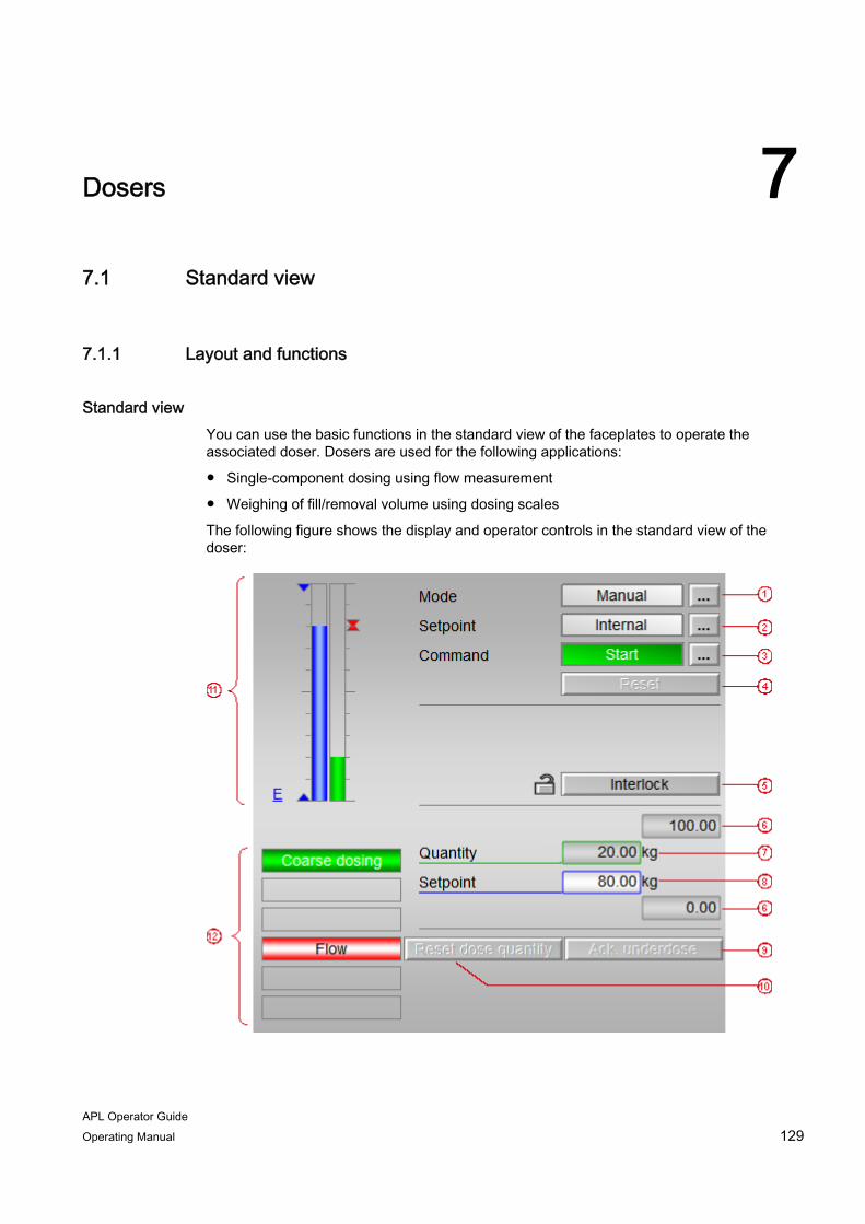
APL Operator Guide Operating Manual 129
Dosers 77.1 Standard view
7.1.1 Layout and functions
Standard view You can use the basic functions in the standard view of the faceplates to operate the associated doser. Dosers are used for the following applications:
● Single-component dosing using flow measurement
● Weighing of fill/removal volume using dosing scales
The following figure shows the display and operator controls in the standard view of the doser:
7 Dosers 7.1 Standard view
APL Operator Guide 130 Operating Manual
1. Operating mode
For dosers, you can switch between the following operating modes:
– Manual mode
– Automatic mode
– Local mode
– Out of service
For additional information on the operating modes, refer to "Switching operating modes (Page 47)".
2. Setpoint specification
You can find additional information on changing the setpoint under "Switch setpoint specification (Page 56)".
3. Operating state
For information on the operating state, refer to "Switching the operating mode (Page 131)".
4. Resetting after interlocks and errors
For additional information on resets, refer to "Resetting after interlocks and errors (Page 141)".
5. Interlock functions and states
For additional information on interlocks, refer to "Display of the interlock status (Page 68)".
6. Scale range of setpoint
The scale range provides information about the display area of the bar graph (11). The values of the scale range cannot be edited in the faceplate.
7. Dose quantity (current process value)
You can find information on simulation of the process value under "Simulate dose quantity (Page 134)".
8. Setpoint
You can find additional information on changing the setpoint under "Change the quantity setpoint (Page 138)".
9. Acknowledge underdosing
You can find information on acknowledging underdosing under "Acknowledge underdosing (Page 139)".
10. Reset dose quantity
You can find information on resetting the dose quantity under "Reset dose quantity (Page 136)".
7 Dosers 7.1 Standard view
APL Operator Guide Operating Manual 131
11. Bar graph
You can find information on elements of the bar graph under "Bar graph (Page 144)".
12. Additional information
You can find information about displays in this area under "Additional information about the operating state (Page 142)".
Depending on the configuration, the following display and control elements are also displayed in the standard view of the faceplate:
● Display of auxiliary values
For additional information refer to "Display of auxiliary values (Page 73)".
● Navigation button to the standard view of another faceplate
For additional information refer to "Opening additional faceplates (Page 63)".
7.1.2 Switching the operating mode
Introduction You can change the operating mode of dosers using the following commands:
● Start
The dosing procedure starts.
● Cancel
The dosing procedure is aborted. This command is also displayed when the dose quantity has been reached.
● Pause
The dosing procedure is stopped and can be continued with the "Continue" command.
● Continue
The dosing procedure is continued.
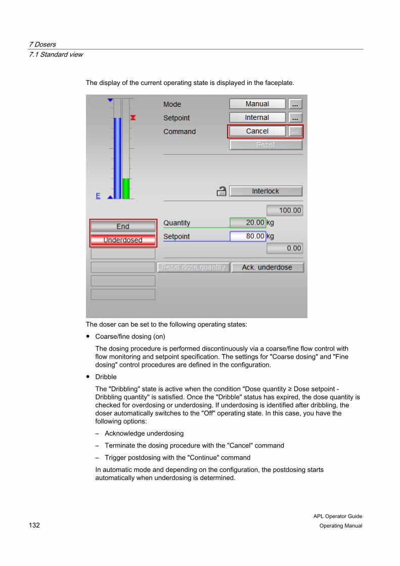
7 Dosers 7.1 Standard view
APL Operator Guide 132 Operating Manual
The display of the current operating state is displayed in the faceplate.
The doser can be set to the following operating states:
● Coarse/fine dosing (on)
The dosing procedure is performed discontinuously via a coarse/fine flow control with flow monitoring and setpoint specification. The settings for "Coarse dosing" and "Fine dosing" control procedures are defined in the configuration.
● Dribble
The "Dribbling" state is active when the condition "Dose quantity ≥ Dose setpoint - Dribbling quantity" is satisfied. Once the "Dribble" status has expired, the dose quantity is checked for overdosing or underdosing. If underdosing is identified after dribbling, the doser automatically switches to the "Off" operating state. In this case, you have the following options:
– Acknowledge underdosing
– Terminate the dosing procedure with the "Cancel" command
– Trigger postdosing with the "Continue" command
In automatic mode and depending on the configuration, the postdosing starts automatically when underdosing is determined.

7 Dosers 7.1 Standard view
APL Operator Guide Operating Manual 133
● Pausing
The dosing procedure is paused.
● Off
The doser is placed in this state if any of the following events occur:
– An flow alarm is triggered.
– An interlock is activated.
– Underdosing is identified after the dribble time.
● End
The doser is placed in this state if any of the following events occur:
– The dose quantity is reached.
– The "Cancel" command is executed.
– The underdosing is acknowledged.
– The dose quantity is below the low tolerance limit after the expiration of the dribble time.
● Taring
The doser is placed in this state if there is an instable measured value at the start of a scale dosing.
You can find additional information about displays in this area under "Additional information about the operating state (Page 142)".
Requirement You have the required operator permissions.
For additional information refer to "Operator permission and enable (Page 29)".
Procedure To change the operating state of a doser, follow these steps:
1. Open the faceplate.
2. Click on the button to open the operating window.
The operating window is opened as an extension of the faceplate.
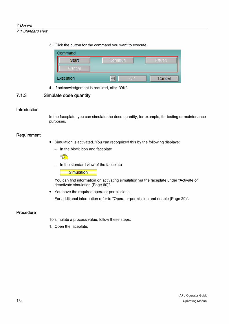
7 Dosers 7.1 Standard view
APL Operator Guide 134 Operating Manual
3. Click the button for the command you want to execute.
4. If acknowledgement is required, click "OK".
7.1.3 Simulate dose quantity
Introduction In the faceplate, you can simulate the dose quantity, for example, for testing or maintenance purposes.
Requirement ● Simulation is activated. You can recognized this by the following displays:
– In the block icon and faceplate
– In the standard view of the faceplate
You can find information on activating simulation via the faceplate under "Activate or deactivate simulation (Page 60)".
● You have the required operator permissions.
For additional information refer to "Operator permission and enable (Page 29)".
Procedure To simulate a process value, follow these steps:
1. Open the faceplate.

7 Dosers 7.1 Standard view
APL Operator Guide Operating Manual 135
2. Click on the input box of the dose quantity.
The operating window is opened as an extension of the faceplate.
3. Enter a value.
You can find additional information on changing values in the operating window under "Change values (Page 51)".
4. If acknowledgement is required, click "OK".
7 Dosers 7.1 Standard view
APL Operator Guide 136 Operating Manual
7.1.4 Reset dose quantity
Introduction You can reset the value of the current dose quantity in the faceplate. Reset is only possible in the "End" operating state of the doser.
For additional information on the operating states, refer to "Switching the operating mode (Page 131)".
Requirement ● The doser is in the "End" state.
● You have the required operator permissions.
For additional information refer to "Operator permission and enable (Page 29)".
Procedure To reset the dose quantity, follow these steps:
1. Open the faceplate.

7 Dosers 7.1 Standard view
APL Operator Guide Operating Manual 137
2. Click "Reset dose quantity".
The operating window is opened as an extension of the faceplate.
3. Click "Reset".
4. If acknowledgement is required, click "OK".

7 Dosers 7.1 Standard view
APL Operator Guide 138 Operating Manual
7.1.5 Change the quantity setpoint
Introduction The dosing procedure always requires a setpoint for the dose quantity. The setpoints for the coarse and fine flow control can be calculated from the quantity setpoint. You can change the quantity setpoint in the standard view of the faceplate.
Requirement You have the required operator permissions.
For additional information refer to "Operator permission and enable (Page 29)".
Procedure To change the setpoint for the dose quantity, follow these steps:
1. Open the faceplate.
2. Click on the input box of the setpoint.
The operating window is opened as an extension of the faceplate.

7 Dosers 7.1 Standard view
APL Operator Guide Operating Manual 139
3. Enter the desired value.
You can find additional information on changing values in the operating window under "Change values (Page 51)".
4. If acknowledgement is required, click "OK".
7.1.6 Acknowledge underdosing
Introduction Underdosing has occurred when the current dose quantity has not reached the specified low limit. For additional information on the limits of a doser, refer to "Limit view (Page 150)".
Requirement ● Underdosing has occurred.
● You have the required operator permissions.
For additional information refer to "Operator permission and enable (Page 29)".
Procedure To acknowledge underdosing, follow these steps.
1. Open the faceplate.
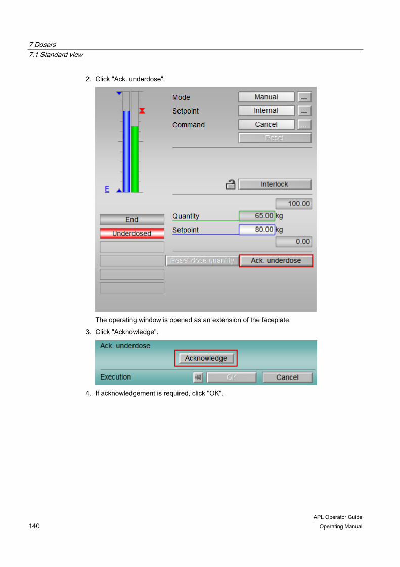
7 Dosers 7.1 Standard view
APL Operator Guide 140 Operating Manual
2. Click "Ack. underdose".
The operating window is opened as an extension of the faceplate.
3. Click "Acknowledge".
4. If acknowledgement is required, click "OK".
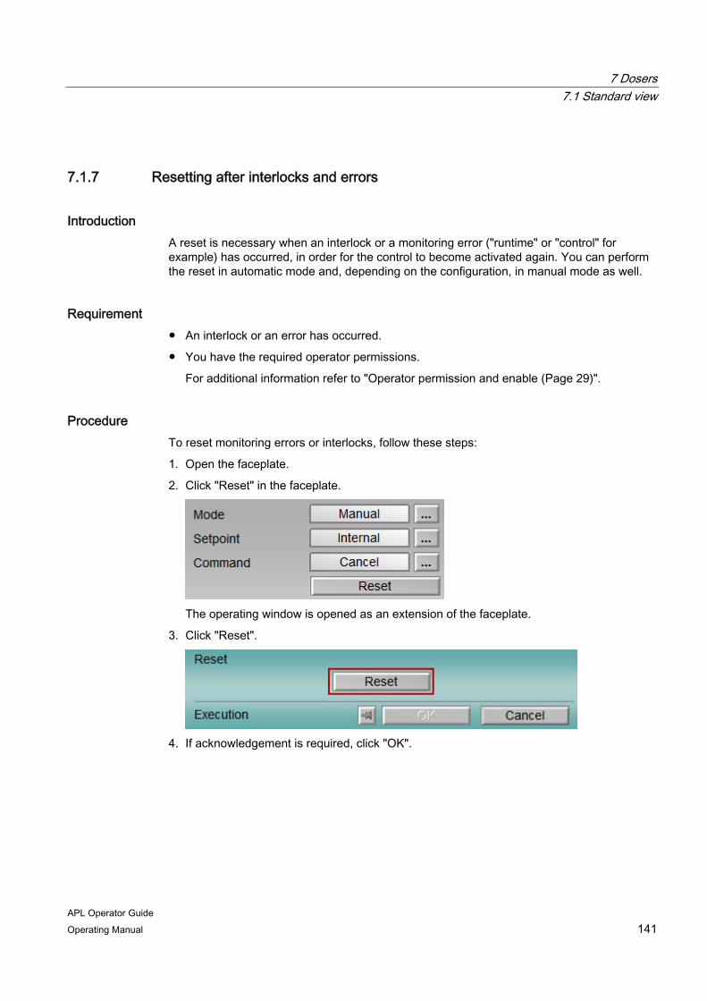
7 Dosers 7.1 Standard view
APL Operator Guide Operating Manual 141
7.1.7 Resetting after interlocks and errors
Introduction A reset is necessary when an interlock or a monitoring error ("runtime" or "control" for example) has occurred, in order for the control to become activated again. You can perform the reset in automatic mode and, depending on the configuration, in manual mode as well.
Requirement ● An interlock or an error has occurred.
● You have the required operator permissions.
For additional information refer to "Operator permission and enable (Page 29)".
Procedure To reset monitoring errors or interlocks, follow these steps:
1. Open the faceplate.
2. Click "Reset" in the faceplate.
The operating window is opened as an extension of the faceplate.
3. Click "Reset".
4. If acknowledgement is required, click "OK".
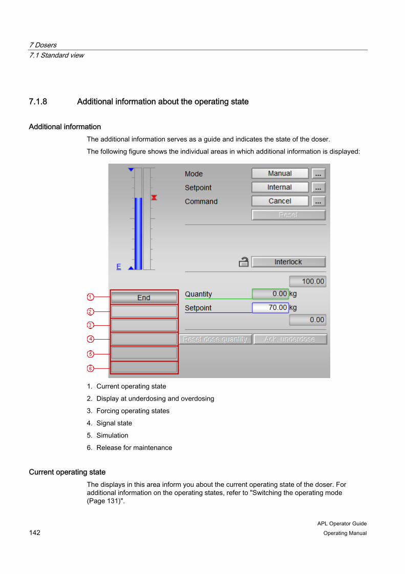
7 Dosers 7.1 Standard view
APL Operator Guide 142 Operating Manual
7.1.8 Additional information about the operating state
Additional information The additional information serves as a guide and indicates the state of the doser.
The following figure shows the individual areas in which additional information is displayed:
1. Current operating state
2. Display at underdosing and overdosing
3. Forcing operating states
4. Signal state
5. Simulation
6. Release for maintenance
Current operating state The displays in this area inform you about the current operating state of the doser. For additional information on the operating states, refer to "Switching the operating mode (Page 131)".
7 Dosers 7.1 Standard view
APL Operator Guide Operating Manual 143
Display at underdosing and overdosing The displays in this area indicate whether underdosing or overdosing has occurred.
Underdosing has occurred if, after the expiration of dribbling time or post dose time, the setpoint has not been reached and the current dose quantity is below the dosing limit.
Overdosing has occurred if, after the expiration of dribbling time or post dose time, the setpoint has been exceeded and the current dose quantity is above the dosing limit.
The dosing limits for underdosing and overdosing are shown in the limit view and can be edited there.
Forcing operating states When you force operating states, the doser is set to a new state regardless of the currently pending control. The forcing of operating states cannot be influenced via the faceplate.
The following table shows the displays that can be shown in this area of the standard view:
Display Meaning Forced start The start of the dosing procedure was forced. Forced pause The stop of the dosing procedure was forced. Forced resume The continuation of the dosing procedure was
forced. Forced stop The stop of the dosing procedure was forced. Request 0/1 A reset of the process tag is expected.
Signal state The following displays appear in this area:
● Flow
The "Flow" display appears when a flow limit is violated.
● Invalid signal
"Invalid signal" is displayed when invalid combinations of related input signals occur in automatic mode. For example, the "Pause" and "Continue" commands cannot be executed simultaneously.
Simulation For additional information on simulation refer to "Activate or deactivate simulation (Page 60)".
Maintenance For additional information on release for maintenance refer to "Activate or deactivate release for maintenance (Page 61)".
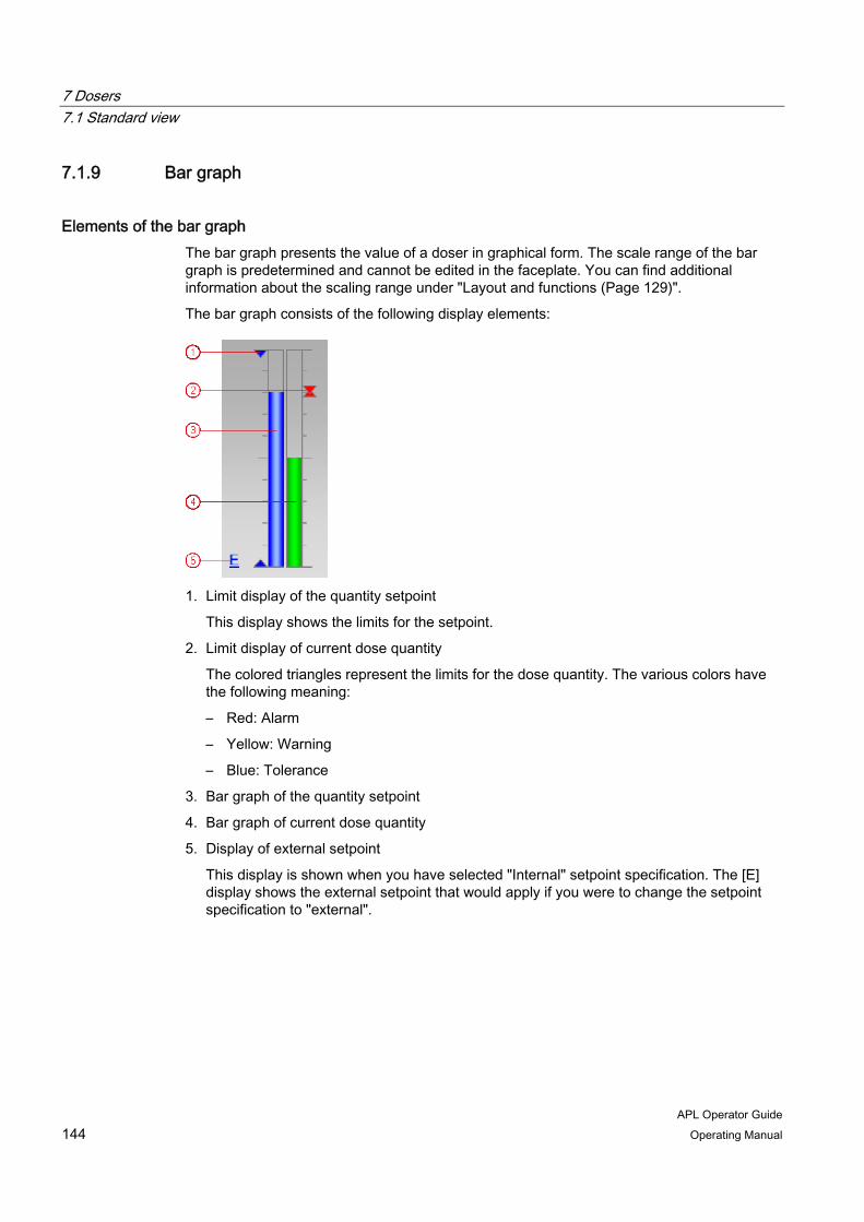
7 Dosers 7.1 Standard view
APL Operator Guide 144 Operating Manual
7.1.9 Bar graph
Elements of the bar graph The bar graph presents the value of a doser in graphical form. The scale range of the bar graph is predetermined and cannot be edited in the faceplate. You can find additional information about the scaling range under "Layout and functions (Page 129)".
The bar graph consists of the following display elements:
1. Limit display of the quantity setpoint
This display shows the limits for the setpoint.
2. Limit display of current dose quantity
The colored triangles represent the limits for the dose quantity. The various colors have the following meaning:
– Red: Alarm
– Yellow: Warning
– Blue: Tolerance
3. Bar graph of the quantity setpoint
4. Bar graph of current dose quantity
5. Display of external setpoint
This display is shown when you have selected "Internal" setpoint specification. The [E] display shows the external setpoint that would apply if you were to change the setpoint specification to "external".
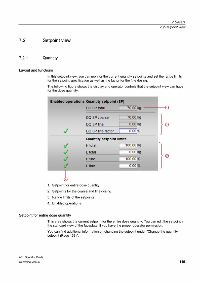
7 Dosers 7.2 Setpoint view
APL Operator Guide Operating Manual 145
7.2 Setpoint view
7.2.1 Quantity
Layout and functions In this setpoint view, you can monitor the current quantity setpoints and set the range limits for the setpoint specification as well as the factor for the fine dosing.
The following figure shows the display and operator controls that the setpoint view can have for the dose quantity:
1. Setpoint for entire dose quantity
2. Setpoints for the coarse and fine dosing
3. Range limits of the setpoints
4. Enabled operations
Setpoint for entire dose quantity This area shows the current setpoint for the entire dose quantity. You can edit the setpoint in the standard view of the faceplate, if you have the proper operator permission.
You can find additional information on changing the setpoint under "Change the quantity setpoint (Page 138)".
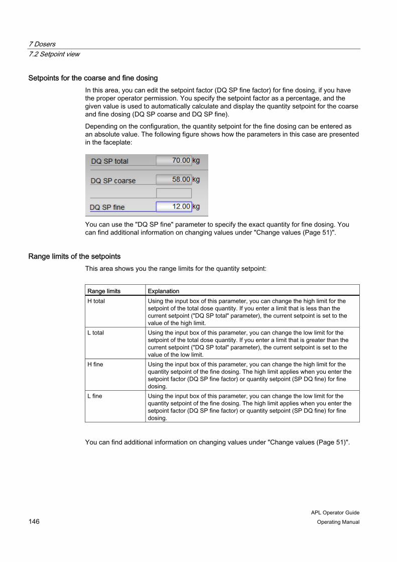
7 Dosers 7.2 Setpoint view
APL Operator Guide 146 Operating Manual
Setpoints for the coarse and fine dosing In this area, you can edit the setpoint factor (DQ SP fine factor) for fine dosing, if you have the proper operator permission. You specify the setpoint factor as a percentage, and the given value is used to automatically calculate and display the quantity setpoint for the coarse and fine dosing (DQ SP coarse and DQ SP fine).
Depending on the configuration, the quantity setpoint for the fine dosing can be entered as an absolute value. The following figure shows how the parameters in this case are presented in the faceplate:
You can use the "DQ SP fine" parameter to specify the exact quantity for fine dosing. You can find additional information on changing values under "Change values (Page 51)".
Range limits of the setpoints This area shows you the range limits for the quantity setpoint:
Range limits Explanation H total Using the input box of this parameter, you can change the high limit for the
setpoint of the total dose quantity. If you enter a limit that is less than the current setpoint ("DQ SP total" parameter), the current setpoint is set to the value of the high limit.
L total Using the input box of this parameter, you can change the low limit for the setpoint of the total dose quantity. If you enter a limit that is greater than the current setpoint ("DQ SP total" parameter), the current setpoint is set to the value of the low limit.
H fine Using the input box of this parameter, you can change the high limit for the quantity setpoint of the fine dosing. The high limit applies when you enter the setpoint factor (DQ SP fine factor) or quantity setpoint (SP DQ fine) for fine dosing.
L fine Using the input box of this parameter, you can change the low limit for the quantity setpoint of the fine dosing. The high limit applies when you enter the setpoint factor (DQ SP fine factor) or quantity setpoint (SP DQ fine) for fine dosing.
You can find additional information on changing values under "Change values (Page 51)".

7 Dosers 7.2 Setpoint view
APL Operator Guide Operating Manual 147
Enabled operations The status of the enabled operation is displayed in this area. For additional information refer to "Enabled operations (Page 31)".
7.2.2 Flow
Layout and functions In this setpoint view, you can monitor the current values for the flow control and, if you have the proper operator permission, edit setpoints and their range limits.
The following figure shows the display and operator controls that the setpoint view can have for the flow control:
1. Scale range of the bar graph (6)
2. Current process value
3. Active setpoint for the flow
4. Setpoints for coarse and fine dosing
5. Range limits of the setpoints
6. Bar graph
7. Enabled operations
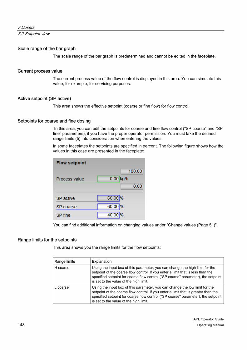
7 Dosers 7.2 Setpoint view
APL Operator Guide 148 Operating Manual
Scale range of the bar graph The scale range of the bar graph is predetermined and cannot be edited in the faceplate.
Current process value The current process value of the flow control is displayed in this area. You can simulate this value, for example, for servicing purposes.
Active setpoint (SP active) This area shows the effective setpoint (coarse or fine flow) for flow control.
Setpoints for coarse and fine dosing In this area, you can edit the setpoints for coarse and fine flow control ("SP coarse" and "SP fine" parameters), if you have the proper operator permission. You must take the defined range limits (5) into consideration when entering the values.
In some faceplates the setpoints are specified in percent. The following figure shows how the values in this case are presented in the faceplate:
You can find additional information on changing values under "Change values (Page 51)".
Range limits for the setpoints This area shows you the range limits for the flow setpoints:
Range limits Explanation H coarse Using the input box of this parameter, you can change the high limit for the
setpoint of the coarse flow control. If you enter a limit that is less than the specified setpoint for coarse flow control ("SP coarse" parameter), the setpoint is set to the value of the high limit.
L coarse Using the input box of this parameter, you can change the low limit for the setpoint of the coarse flow control. If you enter a limit that is greater than the specified setpoint for coarse flow control ("SP coarse" parameter), the setpoint is set to the value of the high limit.

7 Dosers 7.2 Setpoint view
APL Operator Guide Operating Manual 149
Range limits Explanation H fine Using the input box of this parameter, you can change the high limit for the
setpoint of the fine flow control. If you enter a limit that is less than the specified setpoint for fine flow control ("SP fine" parameter), the setpoint is set to the value of the high limit.
L fine Using the input box of this parameter, you can change the low limit for the setpoint of the fine flow control. If you enter a limit that is greater than the specified setpoint for fine flow control ("SP fine" parameter), the setpoint is set to the value of the high limit.
You can find additional information on changing values under "Change values (Page 51)".
Bar graph The bar graph represents the current process value (2) and the active setpoint (3) in graphical form. The scale range of the bar graph (1) is predetermined and cannot be edited in the faceplate.
The following figure shows the elements of the bar graph:
1. Limit display of the active setpoint for the flow
2. Limit for the process value
These triangles show limits for the flow limits. The flow limits are set in the limit view.
3. Bar graph of the active setpoint for the flow
4. Bar graph of the process value
If the setpoints have been entered as percentages, the bar graph of the active setpoint and the corresponding limit displays are not available.
Enabled operations The status of the enabled operation is displayed in this area. For additional information refer to "Enabled operations (Page 31)".

7 Dosers 7.3 Limit view
APL Operator Guide 150 Operating Manual
7.3 Limit view
Layout and functions In the limit view, you can monitor limits and change them based on the process, if you have the proper operator permission. If the limits are reached or exceeded, a corresponding "Alarm" class message is triggered.
The limit view consists of the following areas:
● Dosing limits
● Flow limits (coarse)
● Flow limits (fine)
● Limit creep rate
● Enabled operations
Dosing limits
The limits for monitoring the dose quantity are displayed in this area. The following table shows the limits that you can change with the proper operator permission:
Limit Explanation Overdosing Limit for the overdosing
The "overdosed" state occurs when the difference between the current dose quantity and the quantity setpoint is greater than the limit for overdosing. If an overdose occurs, a corresponding display appears in the standard view.
Underdosing Limit for the underdosing The "underdosed" state occurs when the difference between the quantity setpoint and the current dose quantity is greater than the limit for underdosing. If an underdose occurs, a corresponding display appears in the standard view.
You can find additional information on changing values under "Change values (Page 51)".

7 Dosers 7.3 Limit view
APL Operator Guide Operating Manual 151
Flow limits (coarse)
The limits for monitoring the coarse flow are displayed in this area. The following table shows the limits that you can change with the proper operator permission:
Limit Explanation H alarm High limit for triggering a message of "Alarm" class L alarm Low limit for triggering a message of "Alarm" class Hysteresis You can configure a hysteresis for the limits, for example, to suppress signal
flutter.
You can find additional information on changing values under "Change values (Page 51)".
Flow limits (fine)
The limits for monitoring the fine flow are displayed in this area. The following table shows the limits that you can change with the proper operator permission:
Limit Explanation H alarm High limit for triggering a message of "Alarm" class L alarm Low limit for triggering a message of "Alarm" class Hysteresis You can configure a hysteresis for the limits, for example, to suppress signal
flutter.
You can find additional information on changing values under "Change values (Page 51)".
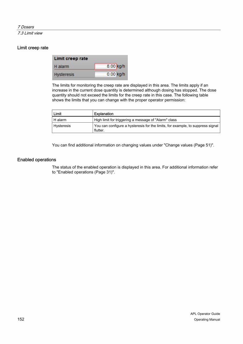
7 Dosers 7.3 Limit view
APL Operator Guide 152 Operating Manual
Limit creep rate
The limits for monitoring the creep rate are displayed in this area. The limits apply if an increase in the current dose quantity is determined although dosing has stopped. The dose quantity should not exceed the limits for the creep rate in this case. The following table shows the limits that you can change with the proper operator permission:
Limit Explanation H alarm High limit for triggering a message of "Alarm" class Hysteresis You can configure a hysteresis for the limits, for example, to suppress signal
flutter.
You can find additional information on changing values under "Change values (Page 51)".
Enabled operations The status of the enabled operation is displayed in this area. For additional information refer to "Enabled operations (Page 31)".

7 Dosers 7.4 Parameter view
APL Operator Guide Operating Manual 153
7.4 Parameter view
Layout and functions In the parameter view, you can monitor and change parameters values, as well as enable or disable simulation and the release for maintenance. The following figure shows the display and operator controls in the parameter view for dosers:
1. Activate bumpless changeover
2. Settings for dribbling and postdosing
3. Settings for automatically calculating the dribbling quantity
4. Simulation and release for maintenance
5. Enabled operations
Activate bumpless changeover You can use the "SP := SP external" check box to enable bumpless changeover from the external to the internal setpoint (checked) or disable it (cleared). The confirmation of each change of state is made in the operating window.
With bumpless changeover, the internal setpoint is tracked to the external setpoint. This avoids unwanted jumps in the output signal when switching the setpoint specification.

7 Dosers 7.4 Parameter view
APL Operator Guide 154 Operating Manual
Settings for dribbling and postdosing You can make the following settings in this area:
Parameter Explanation Post dose time Time for postdosing
Postdosing is necessary if an underdose is determined following expiration of the dribble time.
Dribble time Time for the dribble After expiration of the specified dribble time, the quantity is checked for underdosing or overdosing.
Dribble quantity Dribble quantity If the dose quantity reaches the difference between the setpoint and the dribble quantity, the doser is set to the "Dribble" state and the dribble time is triggered.
You can find additional information on changing values under "Change values (Page 51)".
Settings for automatically calculating the dribbling quantity You can make the following settings in this area:
Parameter Explanation On You can use the "On" check box to enable automatic calculation of the dribble
quantity (checked) or disable it (cleared). The values of the last dosing are used to calculate the dribble quantity. The calculation is performed in the "End" operating state.
Weighting factor The weighting factor is the effect of the underdose quantity on the corrected calculation of the dribbling quantity as a percentage.
Maximum This parameter specifies the limit for the calculation of the dribbling quantity. The calculated dribbling quantity cannot exceed the value of the "Maximum" parameter.
Calc. value Display of the dribbling quantity
You can find additional information on changing values under "Change values (Page 51)".
Simulation and release for maintenance The status of the following functions is displayed in this area:
● Simulation
For additional information on simulation refer to "Activate or deactivate simulation (Page 60)".
● Release for maintenance
For additional information on release for maintenance refer to "Activate or deactivate release for maintenance (Page 61)".
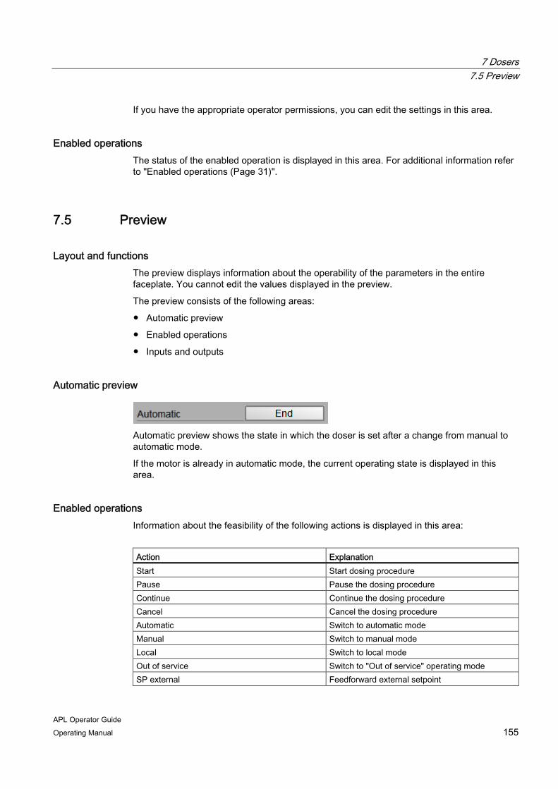
7 Dosers 7.5 Preview
APL Operator Guide Operating Manual 155
If you have the appropriate operator permissions, you can edit the settings in this area.
Enabled operations The status of the enabled operation is displayed in this area. For additional information refer to "Enabled operations (Page 31)".
7.5 Preview
Layout and functions The preview displays information about the operability of the parameters in the entire faceplate. You cannot edit the values displayed in the preview.
The preview consists of the following areas:
● Automatic preview
● Enabled operations
● Inputs and outputs
Automatic preview
Automatic preview shows the state in which the doser is set after a change from manual to automatic mode.
If the motor is already in automatic mode, the current operating state is displayed in this area.
Enabled operations Information about the feasibility of the following actions is displayed in this area:
Action Explanation Start Start dosing procedure Pause Pause the dosing procedure Continue Continue the dosing procedure Cancel Cancel the dosing procedure Automatic Switch to automatic mode Manual Switch to manual mode Local Switch to local mode Out of service Switch to "Out of service" operating mode SP external Feedforward external setpoint

7 Dosers 7.5 Preview
APL Operator Guide 156 Operating Manual
Action Explanation SP internal Feedforward internal setpoint Change SP Change setpoint Reset dose quantity Reset the dose quantity Reset Reset for interlocks and errors Acknowledge underdosing Reset at underdosing Local operator permission Whether or not the device is released for
operation generally depends on this permission. The local operator permission can be set individually for each device. Devices at a work place can be released or locked independent of each other.
You can find additional information about enabled operations under "Operator permission and enable (Page 29)".
Inputs and outputs This area shows the parameters of the doser with the current control.
The following table shows the parameters that can be shown in this area:
Parameter Control
0: No permisson Permission 1: Enable for starting from the neutral position 0: Safety interlock enabled A reset must be performed once the interlock conditions are gone.
Protection
1: Safety interlock disabled 0: Interlock enabled A reset is not necessary once the interlock conditions are gone.
Interlock
1: Interlock disabled 0: No operation in local mode Local 1: Operation in local mode
Local start 1: Start dosing procedure in local mode Local pause 1: Pause dosing procedure in local mode Local continue 1: Continue dosing procedure in local mode Local cancel 1: Cancel dosing procedure in local mode Coarse dosing 1: Coarse dose active Fine dosing 1: Fine dosing active Dribbling dosing 1: Dribbling active Dose off 1: Switch to "Off" operating state Dose end 1: End dosing

7 Dosers 7.6 Additional views
APL Operator Guide Operating Manual 157
For additional information on the operating states, refer to "Switching the operating mode (Page 131)".
7.6 Additional views
Additional views of the faceplates for dosers The faceplates of dosers also provide the following views:
● Alarm view (Page 37)
● Trend view (Page 41)
● Memo view (Page 45)
● Batch view (Page 47)

7 Dosers 7.6 Additional views
APL Operator Guide 158 Operating Manual
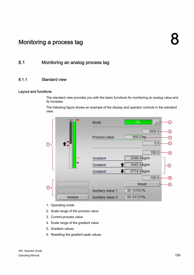
APL Operator Guide Operating Manual 159
Monitoring a process tag 88.1 Monitoring an analog process tag
8.1.1 Standard view
Layout and functions The standard view provides you with the basic functions for monitoring an analog value and its increase.
The following figure shows an example of the display and operator controls in the standard view:
1. Operating mode
2. Scale range of the process value
3. Current process value
4. Scale range of the gradient value
5. Gradient values
6. Resetting the gradient peak values
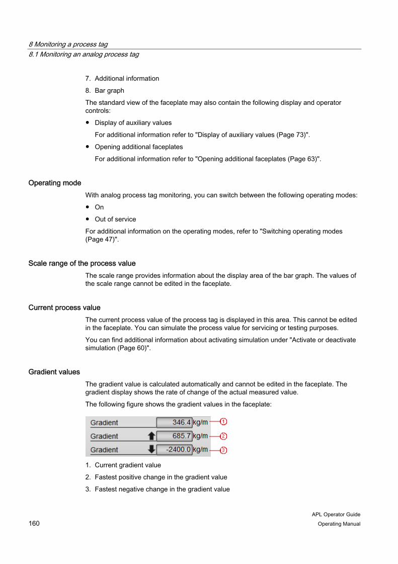
8 Monitoring a process tag 8.1 Monitoring an analog process tag
APL Operator Guide 160 Operating Manual
7. Additional information
8. Bar graph
The standard view of the faceplate may also contain the following display and operator controls:
● Display of auxiliary values
For additional information refer to "Display of auxiliary values (Page 73)".
● Opening additional faceplates
For additional information refer to "Opening additional faceplates (Page 63)".
Operating mode With analog process tag monitoring, you can switch between the following operating modes:
● On
● Out of service
For additional information on the operating modes, refer to "Switching operating modes (Page 47)".
Scale range of the process value The scale range provides information about the display area of the bar graph. The values of the scale range cannot be edited in the faceplate.
Current process value The current process value of the process tag is displayed in this area. This cannot be edited in the faceplate. You can simulate the process value for servicing or testing purposes.
You can find additional information about activating simulation under "Activate or deactivate simulation (Page 60)".
Gradient values The gradient value is calculated automatically and cannot be edited in the faceplate. The gradient display shows the rate of change of the actual measured value.
The following figure shows the gradient values in the faceplate:
1. Current gradient value
2. Fastest positive change in the gradient value
3. Fastest negative change in the gradient value
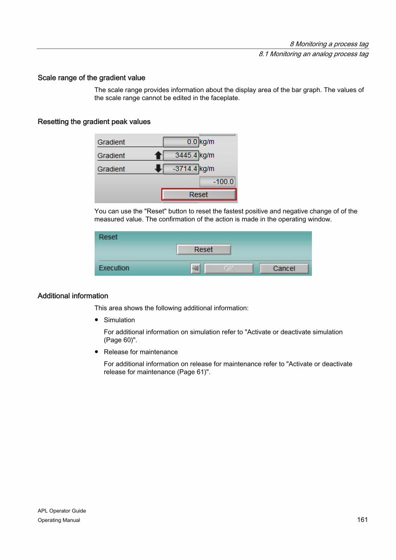
8 Monitoring a process tag 8.1 Monitoring an analog process tag
APL Operator Guide Operating Manual 161
Scale range of the gradient value The scale range provides information about the display area of the bar graph. The values of the scale range cannot be edited in the faceplate.
Resetting the gradient peak values
You can use the "Reset" button to reset the fastest positive and negative change of of the measured value. The confirmation of the action is made in the operating window.
Additional information This area shows the following additional information:
● Simulation
For additional information on simulation refer to "Activate or deactivate simulation (Page 60)".
● Release for maintenance
For additional information on release for maintenance refer to "Activate or deactivate release for maintenance (Page 61)".
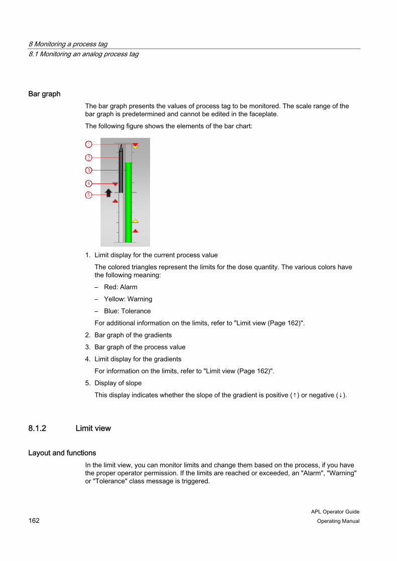
8 Monitoring a process tag 8.1 Monitoring an analog process tag
APL Operator Guide 162 Operating Manual
Bar graph The bar graph presents the values of process tag to be monitored. The scale range of the bar graph is predetermined and cannot be edited in the faceplate.
The following figure shows the elements of the bar chart:
1. Limit display for the current process value
The colored triangles represent the limits for the dose quantity. The various colors have the following meaning:
– Red: Alarm
– Yellow: Warning
– Blue: Tolerance
For additional information on the limits, refer to "Limit view (Page 162)".
2. Bar graph of the gradients
3. Bar graph of the process value
4. Limit display for the gradients
For information on the limits, refer to "Limit view (Page 162)".
5. Display of slope
This display indicates whether the slope of the gradient is positive (↑) or negative (↓).
8.1.2 Limit view
Layout and functions In the limit view, you can monitor limits and change them based on the process, if you have the proper operator permission. If the limits are reached or exceeded, an "Alarm", "Warning" or "Tolerance" class message is triggered.

8 Monitoring a process tag 8.1 Monitoring an analog process tag
APL Operator Guide Operating Manual 163
The limit view consists of the following areas:
● Process value limits (PV)
● Gradient limits
Process value limits (PV)
The limits for monitoring the process value are displayed in this area. The following table shows the limits that you can change based on the process with the proper operator permission:
Limit Explanation H alarm High limit for triggering a message of "Alarm"
class H warning High limit for triggering a message of "Warning"
class H tolerance High limit for triggering a message of "Tolerance"
class Hysteresis You can configure a hysteresis for the limits, for
example, to suppress signal flutter. L tolerance Low limit for triggering a message of "Tolerance"
class L warning Low limit for triggering a message of "Warning"
class L alarm Low limit for triggering a message of "Alarm"
class
You can find additional information on changing values in the faceplate under "Change values (Page 51)".

8 Monitoring a process tag 8.1 Monitoring an analog process tag
APL Operator Guide 164 Operating Manual
Gradient limits The limits of the gradient are displayed in this area. The following table shows the limits that you can change based on the process with the proper operator permission:
Limit Explanation H alarm (↑) High limit for the positive slope of the gradient H alarm (↓) High limit for the negative slope of the gradient L alarm (↑↓) Low limit for the absolute gradients
You can find additional information on changing values in the faceplate under "Change values (Page 51)".
Enabled operations The status of the enabled operation is displayed in this area. For additional information refer to "Enabled operations (Page 31)".
8.1.3 Parameter view
Layout and functions In the parameter view, you can monitor and change parameters values, as well as enable or disable simulation and the release for maintenance. The parameter view consists of the following areas:
● Parameter
● Service
● Enabled operations
Parameter
This area displays the limit (dead band) for suppression of values fluctuating around the zero point. You can edit this value if you have the appropriate operator permission.
You can find additional information on changing values under "Change values (Page 51)".
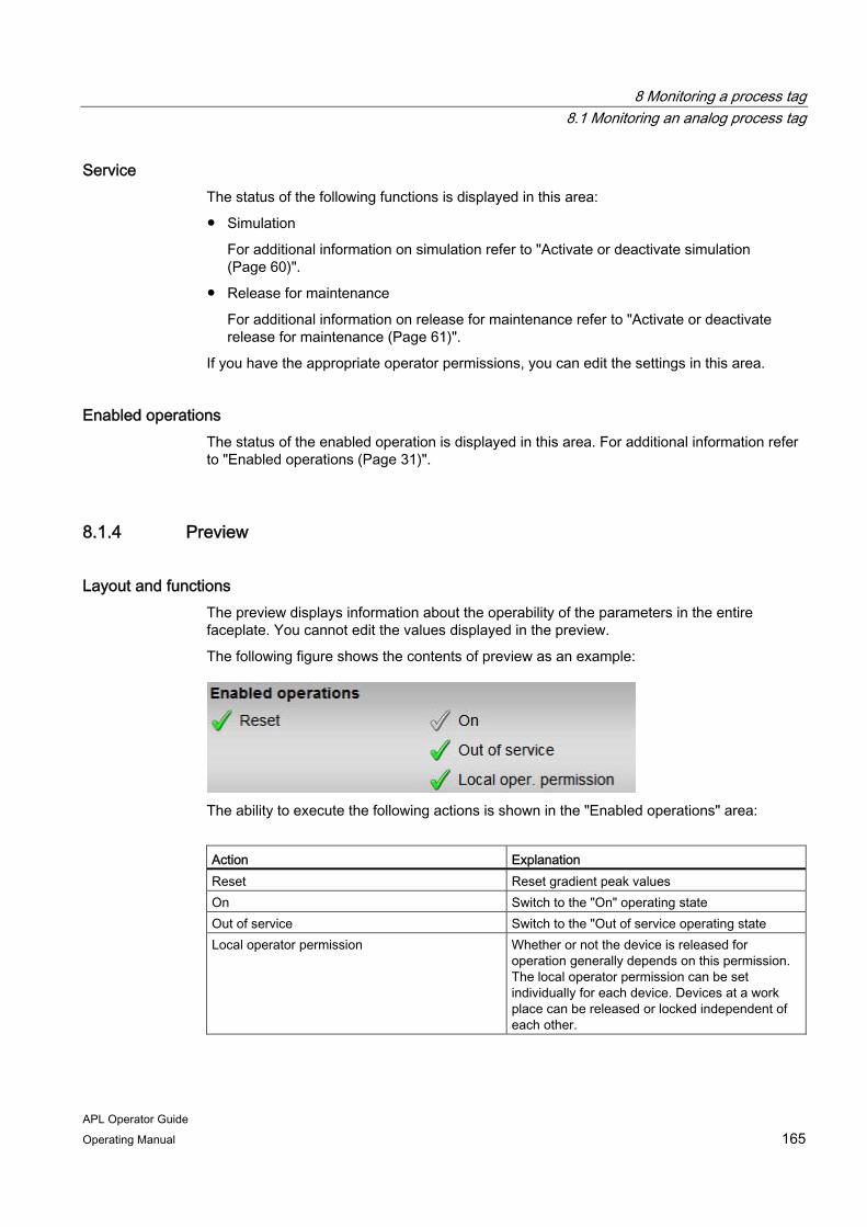
8 Monitoring a process tag 8.1 Monitoring an analog process tag
APL Operator Guide Operating Manual 165
Service The status of the following functions is displayed in this area:
● Simulation
For additional information on simulation refer to "Activate or deactivate simulation (Page 60)".
● Release for maintenance
For additional information on release for maintenance refer to "Activate or deactivate release for maintenance (Page 61)".
If you have the appropriate operator permissions, you can edit the settings in this area.
Enabled operations The status of the enabled operation is displayed in this area. For additional information refer to "Enabled operations (Page 31)".
8.1.4 Preview
Layout and functions The preview displays information about the operability of the parameters in the entire faceplate. You cannot edit the values displayed in the preview.
The following figure shows the contents of preview as an example:
The ability to execute the following actions is shown in the "Enabled operations" area:
Action Explanation Reset Reset gradient peak values On Switch to the "On" operating state Out of service Switch to the "Out of service operating state Local operator permission Whether or not the device is released for
operation generally depends on this permission. The local operator permission can be set individually for each device. Devices at a work place can be released or locked independent of each other.
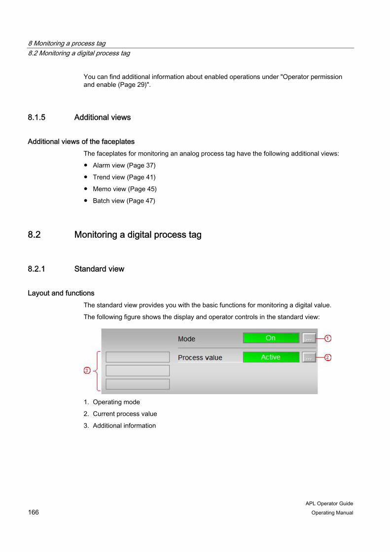
8 Monitoring a process tag 8.2 Monitoring a digital process tag
APL Operator Guide 166 Operating Manual
You can find additional information about enabled operations under "Operator permission and enable (Page 29)".
8.1.5 Additional views
Additional views of the faceplates The faceplates for monitoring an analog process tag have the following additional views:
● Alarm view (Page 37)
● Trend view (Page 41)
● Memo view (Page 45)
● Batch view (Page 47)
8.2 Monitoring a digital process tag
8.2.1 Standard view
Layout and functions The standard view provides you with the basic functions for monitoring a digital value.
The following figure shows the display and operator controls in the standard view:
1. Operating mode
2. Current process value
3. Additional information
8 Monitoring a process tag 8.2 Monitoring a digital process tag
APL Operator Guide Operating Manual 167
The standard view of the faceplate may also contain the following display and operator controls:
● Display of auxiliary values
For additional information refer to "Display of auxiliary values (Page 73)".
● Opening additional faceplates
For additional information refer to "Opening additional faceplates (Page 63)".
Operating mode With digital monitoring stations, you can switch between the following operating modes:
● On
● Out of service
For additional information on the operating modes, refer to "Switching operating modes (Page 47)".
Current process value This area shows the state of the monitored digital value. The texts for the status display are individually set for each project.
You can switch between states when simulation is activated and you have the appropriate operator permission.
Additional information This area shows the following additional information:
● Flutter
The "Flutter" display appears when signal flutter is detected after the expiration of the time to suppress the flutter.
● Simulation
For additional information on simulation refer to "Activate or deactivate simulation (Page 60)".
● Release for maintenance
For additional information on release for maintenance refer to "Activate or deactivate release for maintenance (Page 61)".
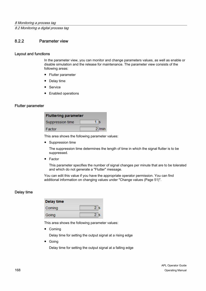
8 Monitoring a process tag 8.2 Monitoring a digital process tag
APL Operator Guide 168 Operating Manual
8.2.2 Parameter view
Layout and functions In the parameter view, you can monitor and change parameters values, as well as enable or disable simulation and the release for maintenance. The parameter view consists of the following areas:
● Flutter parameter
● Delay time
● Service
● Enabled operations
Flutter parameter
This area shows the following parameter values:
● Suppression time
The suppression time determines the length of time in which the signal flutter is to be suppressed.
● Factor
This parameter specifies the number of signal changes per minute that are to be tolerated and which do not generate a "Flutter" message.
You can edit this value if you have the appropriate operator permission. You can find additional information on changing values under "Change values (Page 51)".
Delay time
This area shows the following parameter values:
● Coming
Delay time for setting the output signal at a rising edge
● Going
Delay time for setting the output signal at a falling edge
8 Monitoring a process tag 8.2 Monitoring a digital process tag
APL Operator Guide Operating Manual 169
You can edit this value if you have the appropriate operator permission. You can find additional information on changing values under "Change values (Page 51)".
Service The status of the following functions is displayed in this area:
● Simulation
For additional information on simulation refer to "Activate or deactivate simulation (Page 60)".
● Release for maintenance
For additional information on release for maintenance refer to "Activate or deactivate release for maintenance (Page 61)".
If you have the appropriate operator permissions, you can edit the settings in this area.
Enabled operations The status of the enabled operation is displayed in this area. For additional information refer to "Enabled operations (Page 31)".
8.2.3 Preview
Layout and functions The preview displays information about the operability of the parameters in the entire faceplate. You cannot edit the values displayed in the preview.
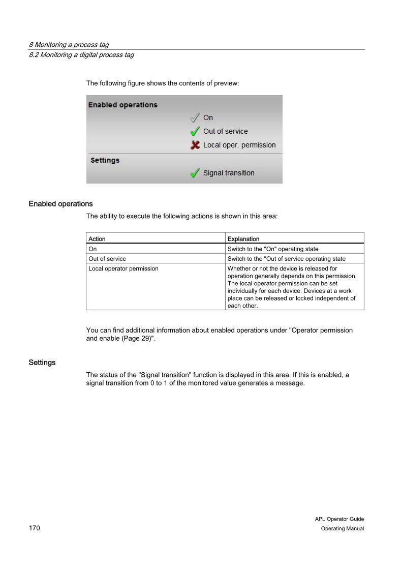
8 Monitoring a process tag 8.2 Monitoring a digital process tag
APL Operator Guide 170 Operating Manual
The following figure shows the contents of preview:
Enabled operations The ability to execute the following actions is shown in this area:
Action Explanation On Switch to the "On" operating state Out of service Switch to the "Out of service operating state Local operator permission Whether or not the device is released for
operation generally depends on this permission. The local operator permission can be set individually for each device. Devices at a work place can be released or locked independent of each other.
You can find additional information about enabled operations under "Operator permission and enable (Page 29)".
Settings The status of the "Signal transition" function is displayed in this area. If this is enabled, a signal transition from 0 to 1 of the monitored value generates a message.

8 Monitoring a process tag 8.2 Monitoring a digital process tag
APL Operator Guide Operating Manual 171
8.2.4 Additional views
Additional views of the faceplates The faceplates for monitoring a digital process tag have the following additional views:
● Alarm view (Page 37)
● Trend view (Page 41)
● Memo view (Page 45)
● Batch view (Page 47)


APL Operator Guide Operating Manual 173
Index
A Acknowledge
Messages, 59 Underdosing, 137
Additional information, 70 Alarm
Icons, 11, 64 Alarm view, 37 Analog value display, 19 Auxiliary values, 72
B Bar graph
Controller (PID), 101 Dosers, 142
Batch display, 72 Batch view, 47 Block icons
Instance name, 11 Layout, 9
Bumpless changeover Controller (PID), 106 Dosers, 151
Bypass Icon, 17 Interlocks, 123 Reset, 124
C Changing
Values, 53 Controller (PID)
Additional information, 99 Bar graph, 101 Bumpless changeover, 106 Change manipulated variable, 98 Change setpoint, 96 Limit view, 103 Parameter view, 106 Preview, 113 Ramp mode, 109 Ramp view, 109
Simulate process value, 95 Standard view, 93
D Dead band, 162 Displays
Coarse/fine dosing, 129 Dribble, 129 End, 129 Flow, 139 Forced, 81, 139 Forced tracking, 81, 99 Invalid signal, 139 Off, 129 Optimizing, 99 Overdosing, 139 Pausing, 129 Request 0/1, 81, 139 Taring, 129 Tracking, 81, 99 Underdosing, 139
Dose quantity Reset, 134 Simulating, 133
Dosers Acknowledge underdosing, 137 Additional information, 139 Bar graph, 142 Bumpless changeover, 151 Change the quantity setpoint, 136 Executing commands, 129 Limit view, 148 Operating states, 129 Parameter view, 151 Preview, 153 Reset dose quantity, 134 Setpoint view (flow), 145 Setpoint view (quantity), 143 Simulate dose quantity, 133 Standard view, 127
E Enabled operations, 31
Icons, 31

Index
APL Operator Guide 174 Operating Manual
F Faceplates
Icons, 64 Layout, 27 Open, 25 Pinning, 62 Views, 32
Force Icon, 17
I Icons
Alarm, 11, 64 Batch display, 72 Bypass, 17 Enabled operations, 31 Force, 17 Interlocks, 18, 67 Memo display, 73 Operating modes, 13 Setpoint specification, 14 Signal status, 15, 66 Tolerance, 11, 64 Tracking, 17 Views, 32 Warning, 11, 64
Initial signal acquisition, 116 Reset, 124
Instance name Displaying and hiding, 11
Interlocks, 67 Bypassing signals, 123 Enable, 67 Icons, 18, 67 Initial signal acquisition, 116 Interlock, 67 Open faceplate, 115 Protection, 67 Resetting a bypass, 124 Resetting an initial signal acquisition, 124 Standard view, 116 Status, 116
L Limit view
Controller (PID), 103 Dosers, 148 Monitoring an analog process tag, 161 Motors, 85
Local operator permission, 29
M Manipulated variable
Changing, 22, 98 Memo
Delete, 44 Display, 73 Store, 44
Memo display, 18, 73 Memo view, 44 Messages
Acknowledge, 59 Locking, 56 Suppressing, 59 Unlocking, 56
Monitoring a digital process tag Parameter view, 166 Preview, 167 Standard view, 164
Monitoring an analog process tag Limit view, 161 Parameter view, 162 Preview, 163 Standard view, 157
Motors Additional information, 81 Limit view, 85 Operating states, 76 Parameter view, 88 Preview, 90 Standard view, 75 Starting, 76 Status display, 83 Stopping, 76
O Open
Faceplates, 25 Operating modes, 47
Icons, 13 Switching, 13, 47
Operating states Changing, 23, 49 Dosers, 129 Motors, 76 Valves, 78
Operating window, 52 Operator permission, 29

Index
APL Operator Guide Operating Manual 175
Operator permission level, 29
P Parameter view
Controller (PID), 106 Dosers, 151 Monitoring a digital process tag, 166 Monitoring an analog process tag, 162 Motors, 88 Valves, 88
Preview Controller (PID), 113 Dosers, 153 Monitoring a digital process tag, 167 Monitoring an analog process tag, 163 Motors, 90 Valves, 90
Process value Simulating, 20, 95
Q Quantity setpoint
Changing, 136
R Ramp mode
Controller (PID), 109 Ramp view
Controller (PID), 109 Release for maintenance
Activate, 61 Deactivate, 61
Reset Resetting after interlocks and errors, 79, 139
S Setpoint
Changing, 21, 96 Setpoint specification, 55
Icons, 14 Switching, 14, 55
Setpoint view Dosers, 143, 145
Signal status, 15, 66 Icons, 15, 66
Simulating
Dose quantity, 133 Process value, 20, 95
Simulation Activate, 60 Deactivate, 60
Standard view Controller (PID), 93 Dosers, 127 Interlocks, 116 Monitoring a digital process tag, 164 Monitoring an analog process tag, 157 Motors, 75 Valves, 75
Status Interlocks, 116
Status display, 23, 70 Motors, 83 Valves, 83
Switch To the block icon, 62
T Tolerance
Icons, 11, 64 Tracking
Icon, 17 Trend view, 40 Trends, 40
U Underdosing
Acknowledge, 137
V Values
Changing, 53 Operability, 51
Valves Additional information, 81 Close, 78 Open, 78 Operating states, 78 Parameter view, 88 Preview, 90 Standard view, 75 Status display, 83
Views Icons, 32

Index
APL Operator Guide 176 Operating Manual
Opening, 33
W Warning
Icons, 11, 64