api mpms 5.3 turbinas
TRANSCRIPT

Copyright American Petroleum Institute Reproduced by IHS under license with ANo reproduction or networking permitted
Manual of Petroleum Measurement StandardsChapter 5—Metering
Section 3—Measurement of Liquid Hydrocarbons by Turbine Meters
,,,,,``,,`,,,,,`,,,``,`-`-`,,`,,`,`,,`---
FIFTH EDITION, SEPTEMBER 2005
PI Licensee=Ecopetrol/5915281004 Not for Resale, 12/07/2005 12:50:42 MST without license from IHS
--`,````

Copyright American Petroleum Institute Reproduced by IHS under license with API Licensee=Ecopetrol/5915281004
Not for Resale, 12/07/2005 12:50:42 MSTNo reproduction or networking permitted without license from IHS
--`,````,,,,,``,,`,,,,,`,,,``,`-`-`,,`,,`,`,,`---

Copyright American Petroleum Institute Reproduced by IHS under license with ANo reproduction or networking permitted
--`,````,,,,,``,,`,,,,,`,,,``,`-`-`,,`,,`,`,,`---
Manual of Petroleum Measurement StandardsChapter 5—MeteringSection 3—Measurement of Liquid
Hydrocarbons by Turbine Meters
Measurement Coordination Department
FIFTH EDITION, SEPTEMBER 2005
PI Licensee=Ecopetrol/5915281004 Not for Resale, 12/07/2005 12:50:42 MST without license from IHS
SPECIAL NOTES
API publications necessarily address problems of a general nature. With respect to partic-ular circumstances, local, state, and federal laws and regulations should be reviewed.
API is not undertaking to meet the duties of employers, manufacturers, or suppliers to warn and properly train and equip their employees, and others exposed, concerning health and safety risks and precautions, nor undertaking their obligations under local, state, or fed-eral laws.
Neither API nor any of API's employees, subcontractors, consultants, committees, or other assignees make any warranty or representation, either express or implied, with respect to the accuracy, completeness, or usefulness of the information contained herein, or assume any liability or responsibility for any use, or the results of such use, of any information or process disclosed in this publication. Neither API nor any of API's employees, subcontrac-tors, consultants, or other assignees represent that use of this publication would not infringe upon privately owned rights.
API publications may be used by anyone desiring to do so. Every effort has been made by the Institute to assure the accuracy and reliability of the data contained in them; however, the Institute makes no representation, warranty, or guarantee in connection with this publication and hereby expressly disclaims any liability or responsibility for loss or damage resulting from its use or for the violation of any authorities having jurisdiction with which this publi-cation may conflict.
API publications are published to facilitate the broad availability of proven, sound engi-neering and operating practices. These publications are not intended to obviate the need for applying sound engineering judgment regarding when and where these publications should be utilized. The formulation and publication of API publications is not intended in any way to inhibit anyone from using any other practices.
Any manufacturer marking equipment or materials in conformance with the marking requirements of an API standard is solely responsible for complying with all the applicable requirements of that standard. API does not represent, warrant, or guarantee that such prod-ucts do in fact conform to the applicable API standard.
All rights reserved. No part of this work may be reproduced, stored in a retrieval system, or transmitted by any means, electronic, mechanical, photocopying, recording, or otherwise,
without prior written permission from the publisher. Contact the Publisher, API Publishing Services, 1220 L Street, N.W., Washington, D.C. 20005.
Copyright © 2005 American Petroleum Institute
Copyright American Petroleum Institute Reproduced by IHS under license with API Licensee=Ecopetrol/5915281004
Not for Resale, 12/07/2005 12:50:42 MSTNo reproduction or networking permitted without license from IHS
--`,````,,,,,``,,`,,,,,`,,,``,`-`-`,,`,,`,`,,`---

FOREWORD
Chapter 5 of the API Manual of Petroleum Measurement Standards (API MPMS) pro-vides recommendations, based on best industry practice, for the custody transfer metering of liquid hydrocarbons. The various sections of this Chapter are intended to be used in conjunc-tion with API MPMS Chapter 6 to provide design criteria for custody transfer metering encountered in most aircraft, marine, pipeline, and terminal applications. The information contained in this chapter may also be applied to non-custody transfer metering.
The chapter deals with the principal types of meters currently in use: displacement meters, turbine meters and Coriolis meters. If other types of meters gain wide acceptance for the measurement of liquid hydrocarbon custody transfers, they will be included in subsequent sections of this chapter.
Nothing contained in any API publication is to be construed as granting any right, by impli-cation or otherwise, for the manufacture, sale, or use of any method, apparatus, or product covered by letters patent. Neither should anything contained in the publication be construed as insuring anyone against liability for infringement of letters patent.
This document was produced under API standardization procedures that ensure appropriate notification and participation in the developmental process and is designated as an API stan-dard. Questions concerning the interpretation of the content of this publication or comments and questions concerning the procedures under which this publication was developed should be directed in writing to the Director of Standards, American Petroleum Institute, 1220 L Street, N.W., Washington, D.C. 20005. Requests for permission to reproduce or translate all or any part of the material published herein should also be addressed to the director.
Generally, API standards are reviewed and revised, reaffirmed, or withdrawn at least every five years. A one-time extension of up to two years may be added to this review cycle. Status of the publication can be ascertained from the API Standards Department, telephone (202) 682-8000. A catalog of API publications and materials is published annually and updated quarterly by API, 1220 L Street, N.W., Washington, D.C. 20005.
Suggested revisions are invited and should be submitted to the Standards and Publications Department, API, 1220 L Street, NW, Washington, DC 20005, [email protected].
iii
Copyright American Petroleum Institute Reproduced by IHS under license with API Licensee=Ecopetrol/5915281004
Not for Resale, 12/07/2005 12:50:42 MSTNo reproduction or networking permitted without license from IHS
--`,````,,,,,``,,`,,,,,`,,,``,`-`-`,,`,,`,`,,`---

Copyright American Petroleum Institute Reproduced by IHS under license with API Licensee=Ecopetrol/5915281004
Not for Resale, 12/07/2005 12:50:42 MSTNo reproduction or networking permitted without license from IHS
--`,````,,,,,``,,`,,,,,`,,,``,`-`-`,,`,,`,`,,`---

CONTENTS
Page
5.3.1 INTRODUCTION. . . . . . . . . . . . . . . . . . . . . . . . . . . . . . . . . . . . . . . . . . . . . . . . . . . . . .1
5.3.2 SCOPE. . . . . . . . . . . . . . . . . . . . . . . . . . . . . . . . . . . . . . . . . . . . . . . . . . . . . . . . . . . . . . .1
5.3.3 FIELD OF APPLICATION . . . . . . . . . . . . . . . . . . . . . . . . . . . . . . . . . . . . . . . . . . . . . .2
5.3.4 REFERENCED PUBLICATIONS . . . . . . . . . . . . . . . . . . . . . . . . . . . . . . . . . . . . . . . .2
5.3.5 FLOW CONDITIONING. . . . . . . . . . . . . . . . . . . . . . . . . . . . . . . . . . . . . . . . . . . . . . . .2
5.3.6 MINIMUM BACK PRESSURE TO PREVENT CAVITATION . . . . . . . . . . . . . . . .2
5.3.7 METER PERFORMANCE . . . . . . . . . . . . . . . . . . . . . . . . . . . . . . . . . . . . . . . . . . . . . .35.3.7.1 Meter Factor . . . . . . . . . . . . . . . . . . . . . . . . . . . . . . . . . . . . . . . . . . . . . . . . . . . . .35.3.7.2 Causes of Variations in Meter Factor . . . . . . . . . . . . . . . . . . . . . . . . . . . . . . . . . .3
APPENDIX A FLOW CONDITIONING TECHNOLOGY WITHOUT STRAIGHTENING ELEMENTS . . . . . . . . . . . . . . . . . . . . . . . . . . . . . . . .7
APPENDIX B SIGNAL GENERATION. . . . . . . . . . . . . . . . . . . . . . . . . . . . . . . . . . . . . .11APPENDIX C RECOMMENDED PRACTICE FOR PROVING TURBINE
METERS AT MANUFACTURERS’ FACILITIES. . . . . . . . . . . . . . . . .13
Figures1 Names of Typical Turbine Meter Parts. . . . . . . . . . . . . . . . . . . . . . . . . . . . . . . . . . . .12 Example of Flow Conditioning Assembly with Tube Type
Straightening Element. . . . . . . . . . . . . . . . . . . . . . . . . . . . . . . . . . . . . . . . . . . . . . . . .33 Effects of Cavitation on Rotor Speed . . . . . . . . . . . . . . . . . . . . . . . . . . . . . . . . . . . . .44 Turbine Meter Performance Characteristics. . . . . . . . . . . . . . . . . . . . . . . . . . . . . . . .5A-1 Piping Configuration in Which a Concentric Reducer Precedes
the Meter Run (Ks = 0.75). . . . . . . . . . . . . . . . . . . . . . . . . . . . . . . . . . . . . . . . . . . . . .7A-2 Piping Configuration in Which a Sweeping Elbow Precedes the
Meter Run (Ks = 1.0). . . . . . . . . . . . . . . . . . . . . . . . . . . . . . . . . . . . . . . . . . . . . . . . . .8A-3 Piping Configuration in Which Two Sweeping Elbows Precede the
Meter Run (Ks = 1.25). . . . . . . . . . . . . . . . . . . . . . . . . . . . . . . . . . . . . . . . . . . . . . . . .8A-4 Piping Configuration in Which Two Sweeping Elbows at Right Angles
Precede the Meter Run (Ks = unknown). . . . . . . . . . . . . . . . . . . . . . . . . . . . . . . . . . .9A-5 Piping Configuration in Which a Valve Precedes the Meter Run (Ks = 2.50). . . . . .9
TableA-1 Values for L and L/D for Figures A-1 Through A-5 . . . . . . . . . . . . . . . . . . . . . . . . .8
v
Copyright American Petroleum Institute Reproduced by IHS under license with API Licensee=Ecopetrol/5915281004
Not for Resale, 12/07/2005 12:50:42 MSTNo reproduction or networking permitted without license from IHS
--`,````,,,,,``,,`,,,,,`,,,``,`-`-`,,`,,`,`,,`---

Copyright American Petroleum Institute Reproduced by IHS under license with API Licensee=Ecopetrol/5915281004
Not for Resale, 12/07/2005 12:50:42 MSTNo reproduction or networking permitted without license from IHS
--`,````,,,,,``,,`,,,,,`,,,``,`-`-`,,`,,`,`,,`---

Copyright AmericaReproduced by IHNo reproduction o
Chapter 5—Metering
Section 3—Measurement of Liquid Hydrocarbons by Turbine Meters
5.3.1 IntroductionAPI MPMS Chapter 5.3, together with general consider-
ations for measurement by meters in API MPMS Chapter 5.1, is intended to describe methods of obtaining accurate quan-tity measurements with turbine meters in liquid hydrocarbon service.
A turbine meter is a flow-measuring device with a rotor that senses the velocity of flowing liquid in a closed conduit (see Figure 1). The flowing liquid causes the rotor to move with a tangential velocity proportional to the average stream velocity (which is true if the drag on the rotor—mechanical and viscous—is negligible). The average stream velocity is assumed to be proportional to the volumetric flow rate (which is true if the cross-sectional flow area through the rotor remains constant). The movement of the rotor can be detected
mechanically, optically, or electrically and is registered. The volume that passes through the meter is determined by prov-ing against a known volume, as discussed in API MPMSChapter 4.
It is recognized that meters other than the types described in Chapter 5.3 are used to meter liquid hydrocarbons. This publication does not endorse or advocate the preferential use of turbine meters, nor does it intend to restrict the develop-ment of other types of meters. Those who use other types of meters may find sections of this chapter useful.
5.3.2 ScopeThis section of API MPMS Chapter 5 covers the unique
installation requirements and performance characteristics of turbine meters in liquid-hydrocarbon service.
Figure 1—Names of Typical Turbine Meter Parts
1n Petroleum Institute S under license with API Licensee=Ecopetrol/5915281004
Not for Resale, 12/07/2005 12:50:42 MSTr networking permitted without license from IHS
--`,````,,,,,``,,`,,,,,`,,,``,`-`-`,,`,,`,`,,`---

2 CHAPTER 5—METERING
Copyright AmReproducedNo reproduc
--`,````,,,,,``,,`,,,,,`,,,``,`-`-`,,`,,`,`,,`---
5.3.3 Field of ApplicationThe field of application of this section is all segments of
the petroleum industry in which dynamic measurement of liq-uid hydrocarbons is required. This section does not apply to the measurement of two-phase fluids.
5.3.4 Referenced PublicationsThe current editions of the following API MPMS Stan-
dards contain information applicable to this chapter:
API Manual of Petroleum Measurement StandardsChapter 4, “Proving Systems”Chapter 5.1, “General Considerations for Measurement by
Meters”Chapter 5.4, “Accessory Equipment for Liquid Meters”Chapter 5.5, “Fidelity and Security of Flow Measurement
Pulsed-Data Transmission Systems”Chapter 7, “Temperature”Chapter 8, “Sampling”Chapter 11, “Physical Properties Data”Chapter 12, “Calculation of Petroleum Quantities”Chapter 13, “Statistical Aspects of Measuring and
Sampling”
5.3.5 Flow Conditioning5.3.5.1 The performance of turbine meters may be affected by swirl and non-uniform velocity profiles that are induced by upstream and downstream piping configurations, valves, pumps, fittings, joint misalignment, protruding gaskets, weld-ing projections, or other obstructions. Flow conditioning shall be used to overcome the adverse effects of swirl and non-uni-form velocity profiles on turbine meter performance.
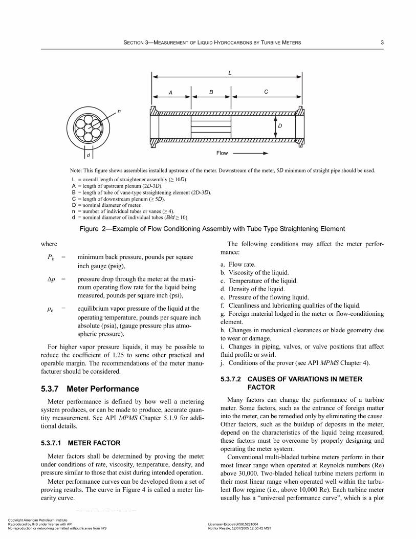
5.3.5.2 Flow conditioning requires the use of sufficient lengths of straight pipe or a combination of straight pipe and flow conditioning elements that are inserted in the meter run upstream (and downstream, if flow through the meter is bidi-rectional) of the turbine meter (see Figure 2).
5.3.5.3 When only straight pipe is used, the liquid shear, or internal friction between the liquid and the pipe wall, shall be sufficient to accomplish the required flow conditioning. Appendix A should be referred to for guidance in applying the technique. Experience has shown that in many installa-tions (e.g., downstream of a simple elbow or Tee) a straight pipe length of 20 meter-bore diameters upstream of the meter and 5 meter-bore diameters downstream of the meter often provides effective flow conditioning.
5.3.5.4 For severe swirl, such as generated by two close coupled elbows out-of-plane (i.e., non-symmetrical swirl) or by a header (i.e., dual symmetrical swirl), a straightening ele-ment (i.e., swirl breaker) type of flow conditioner is required. These types of swirl are slow to dissipate in straight pipe, often existing after 100+ diameters of straight pipe.
5.3.5.5 A straightening element or swirl-breaker type of flow conditioner usually consists of a cluster of tubes, vanes, or equivalent devices that are inserted longitudinally in a sec-tion of straight pipe (see Figure 2). Straightening elements effectively assist flow conditioning by eliminating swirl. Straightening elements may also consist of a series of perfo-rated plates or wire-mesh screens, but these forms normally cause a larger pressure drop than do tubes or vanes.
5.3.5.6 Proper design and construction of the straightening element is important to ensure that swirl is not generated by the straightening element since swirl negates the function of the flow conditioner. The following guidelines are recom-mended to avoid the generation of swirl:
a. The cross-section should be as uniform and symmetrical as possible.b. The design and construction should be rugged enough to resist distortion or movement at high flow rates.c. The general internal construction should be clean and free from welding protrusions and other obstructions.
5.3.5.7 Isolating type flow conditioners, which produce a swirl-free, uniform velocity profile, independent of upstream piping configurations, are typically more sophisti-cated, expensive and higher pressure drop than simple straightening element type flow conditioners. However, in certain installations, they provide a performance advantage and should be considered.
5.3.5.8 Flanges and gaskets shall be internally aligned, and gaskets shall not protrude into the liquid stream. Meters and the adjoining straightening section shall be concentrically aligned.
5.3.6 Minimum Back Pressure to Prevent Cavitation
In the absence of a manufacturer’s recommendation, the numerical value of the minimum back pressure at the outlet of the meter may be calculated with the following expression, which has been commonly used. The calculated back pres-sure has proven to be adequate in most applications, and it may be conservative for some situations.
Pb 2∆p 1.25pe+=
erican Petroleum Institute by IHS under license with API Licensee=Ecopetrol/5915281004
Not for Resale, 12/07/2005 12:50:42 MSTtion or networking permitted without license from IHS
SECTION 3—MEASUREMENT OF LIQUID HYDROCARBONS BY TURBINE METERS 3
Copyright AmericaReproduced by IHNo reproduction o
Figure 2—Example of Flow Conditioning Assembly with Tube Type Straightening Element
where
Pb = minimum back pressure, pounds per square inch gauge (psig),
∆p = pressure drop through the meter at the maxi-mum operating flow rate for the liquid being measured, pounds per square inch (psi),
pe = equilibrium vapor pressure of the liquid at the operating temperature, pounds per square inch absolute (psia), (gauge pressure plus atmo-spheric pressure).
For higher vapor pressure liquids, it may be possible to reduce the coefficient of 1.25 to some other practical and operable margin. The recommendations of the meter manu-facturer should be considered.
5.3.7 Meter PerformanceMeter performance is defined by how well a metering
system produces, or can be made to produce, accurate quan-tity measurement. See API MPMS Chapter 5.1.9 for addi-tional details.
5.3.7.1 METER FACTOR
Meter factors shall be determined by proving the meter under conditions of rate, viscosity, temperature, density, and pressure similar to those that exist during intended operation.
Meter performance curves can be developed from a set of proving results. The curve in Figure 4 is called a meter lin-earity curve.
The following conditions may affect the meter perfor-mance:
a. Flow rate.b. Viscosity of the liquid.c. Temperature of the liquid.d. Density of the liquid.e. Pressure of the flowing liquid.f. Cleanliness and lubricating qualities of the liquid.g. Foreign material lodged in the meter or flow-conditioning element.h. Changes in mechanical clearances or blade geometry due to wear or damage.i. Changes in piping, valves, or valve positions that affect fluid profile or swirl.j. Conditions of the prover (see API MPMS Chapter 4).
5.3.7.2 CAUSES OF VARIATIONS IN METER FACTOR
Many factors can change the performance of a turbine meter. Some factors, such as the entrance of foreign matter into the meter, can be remedied only by eliminating the cause. Other factors, such as the buildup of deposits in the meter, depend on the characteristics of the liquid being measured; these factors must be overcome by properly designing and operating the meter system.
Conventional multi-bladed turbine meters perform in their most linear range when operated at Reynolds numbers (Re) above 30,000. Two-bladed helical turbine meters perform in their most linear range when operated well within the turbu-lent flow regime (i.e., above 10,000 Re). Each turbine meter usually has a “universal performance curve”, which is a plot
n Petroleum Institute S under license with API Licensee=Ecopetrol/5915281004
Not for Resale, 12/07/2005 12:50:42 MSTr networking permitted without license from IHS
--`,````,,,,,``,,`,,,,,`,,,``,`-`-`,,`,,`,`,,`---

4 CHAPTER 5—METERING
Copyright AmReproducedNo reproduc
--`,````,,,,,``,,`,,,,,`,,,``,`-`-`,,`,,`,`,,`---
Figure 3—Effects of Cavitation on Rotor Speed
of k-factor or meter factor versus Re. See Figure 2 above. Re is basically proportional to flow rate divided by kinematic viscosity for a given size meter. Therefore, if both the flow rate and the viscosity are doubled, the k-factor or meter factor for that particular turbine meter will typically not signifi-cantly change since the Re has not changed.
The variables which have the greatest effect on the meter factor are flow rate, viscosity, temperature, deposits, and for-eign matter. If a meter is proved and operated on liquids with inherently identical properties (e.g., viscosity), and operating conditions (e.g., flow rate), the highest level of accuracy can be anticipated. If there are changes in one or more of the liq-uid properties, in the operating conditions and/or in the condi-tion of the meter internals, between the proving and operating cycles, a change in meter factor may result and a new meter factor must be determined by proving.
5.3.7.2.1 FLOW RATE CHANGES
At the low end of the flow rate range the meter factor curve may become less linear and less repeatable than it is at the medium and higher rates (see Figure 4, Applications A and B). If a plot of meter factor versus flow rate has been devel-
oped for a particular liquid, and other variables are constant, a meter factor may be selected from the plot for flow rates within the meter’s operating range; however, for greatest accuracy, the meter should be reproved at the new operating flow rate.
5.3.7.2.2 VISCOSITY CHANGES
Turbine meters are sensitive to variations in viscosity. Since the viscosity of liquid hydrocarbons change with tem-perature, the response of a turbine meter depends on both vis-cosity and temperature. The viscosity of light hydrocarbons such as gasoline essentially remains the same over wide tem-perature changes, and the meter factor remains relatively sta-ble. In heavier, more viscous hydrocarbons such as crude oils, the change in meter factor can be significant because of the viscosity change associated with a relatively small tempera-ture change. It is advisable to reprove the meter frequently when the viscosity of the fluid is known to vary under normal operating conditions. The performance of two-bladed helical type turbine meters is less sensitive to viscosity changes than conventional multi-bladed turbine meters. Also they gener-
erican Petroleum Institute by IHS under license with API Licensee=Ecopetrol/5915281004
Not for Resale, 12/07/2005 12:50:42 MSTtion or networking permitted without license from IHS

SECTION 3—MEASUREMENT OF LIQUID HYDROCARBONS BY TURBINE METERS 5
Copyright AmericaReproduced by IHNo reproduction o
--`,````,,,,,``,,`,,,,,`,,,``,`-`-`,,`,,`,`,,`---
Figure 4—Turbine Meter Performance Characteristics
ally operate satisfactorily at higher viscosities (i.e., at lower Re) than conventional multi-bladed turbine meters.
5.3.7.2.3 TEMPERATURE CHANGES
In addition to affecting changes in viscosity, significant variations in the temperature of the liquid can also affect meter performance by causing changes in the physical dimen-sions of the meter. For greatest accuracy, the meter should be proved in the range of normal operating conditions.
A calculated temperature correction based on the volume weighted average temperature of the delivery, may be used to correct indicated volume to a volume at a base or reference temperature.
5.3.7.2.4 DENSITY CHANGES
A change in the density of the metered liquid can result in significant differences in meter factor, thereby requiring the meter to be proved. For liquids with a relative density of approximately 0.7 or less, consideration must be given to raising the value of the meter’s minimum flow rate to main-tain linearity. The driving torque of the flowing stream on the rotor is proportional to the liquid density multiplied by the square of the liquid velocity.
The driving torque at the minimum flow rate can be main-tained by increasing the minimum flow rate for low density liquids. The amount of increase in minimum flow rate will vary depending on meter size and type, and the magnitude of the change in fluid density. To establish the minimum flow rate, several provings should be made at different rates until a
n Petroleum Institute S under license with API Licensee=Ecopetrol/5915281004
Not for Resale, 12/07/2005 12:50:42 MSTr networking permitted without license from IHS

6 CHAPTER 5—METERING
Copyright AmReproducedNo reproduc
meter factor that yields an acceptable linearity and repeatabil-ity can be determined.
To maintain meter rangeability the maximum flow rate can also be increased, up to the limit allowed by the meter manu-facturer.
5.3.7.2.5 PRESSURE CHANGES
If the pressure of the liquid when it is metered varies from the pressure that existed during proving, the relative volume of the liquid will change as a result of its compressibility. (The physical dimensions of the meter will also change as a result of the expansion or contraction of its housing under pressure.) The potential for error increases in proportion to the difference between the proving and operating conditions. For greatest accuracy, the meter should be proved at the oper-ating conditions (see API MPMS Chapters 4 and 12).
Volumetric corrections for the pressure effects on liquids with vapor pressures above atmospheric pressure are refer-enced to the equilibrium vapor pressure of the liquid at the standard temperature, 60ºF, 15ºC, or 20ºC, rather than to atmospheric pressure, which is the typical reference for liq-uids with measurement temperature vapor pressures below
atmospheric pressure. Both the volume of the liquid in the prover and the registered metered volume are corrected from the measurement pressure to the equivalent volumes at the equilibrium vapor pressure at the standard temperature, 60ºF, 15ºC, or 20ºC. This is a two-step calculation that involves correcting both measurement volumes to the equivalent vol-umes at equilibrium vapor pressure at measurement tempera-ture. The volumes are then corrected to the equivalent volumes at the equilibrium vapor pressure at the standard temperature, 60ºF, 15ºC, or 20ºC. A detailed discussion of this calculation is included in API MPMS Chapter 12.2.
5.3.7.2.6 DEPOSITS OR DEBRIS
Deposits or debris on the turbine meter rotor will decrease the flow area, thereby increasing the liquid velocity, through the rotor. This will increase the rotor velocity, and thus the meter k-factor, for a given flow rate. The effect is less for two-bladed helical turbine meters, but may still be substan-tial, depending on the coating thickness and the size of the meter. Deposits or debris on other internal components of the turbine meter, or on the flow conditioning element, may also have a significant effect on meter performance.
erican Petroleum Institute by IHS under license with API Licensee=Ecopetrol/5915281004
Not for Resale, 12/07/2005 12:50:42 MSTtion or networking permitted without license from IHS
--`,````,,,,,``,,`,,,,,`,,,``,`-`-`,,`,,`,`,,`---

Copyright AmericaReproduced by IHNo reproduction o
APPENDIX A—FLOW CONDITIONING TECHNOLOGY WITHOUT STRAIGHTENING ELEMENTS
A.1 ScopeEffective flow conditioning can often be obtained by using
adequate lengths of straight pipe upstream and downstream of the meter. Appendix A presents an empirical method for com-puting the length of upstream straight pipe required for various installation configurations and operating conditions. Experi-ence has shown that a nominal length of 20 diameters of meter-bore piping upstream of the meter and 5 diameters of meter-bore piping downstream of the meter provide effective condi-tioning in many installations downstream of a simple elbow or tee. However, the required length of upstream piping should be verified for each installation, using the method presented in this appendix. This technique does not predict the length of straight pipe required downstream of the meter. A minimum of 5 diam-eters of meter-bore piping should be provided downstream of the meter unless a different length is supported by the manufac-turer’s recommendations or tests.
A.2 Calculation of Upstream Flow-Conditioning Length
Based on empirical data, the length of straight pipe required upstream of the meter can be calculated using Equa-tion A-1 below:
L 0.35D( ) Ks f⁄( )=
where
L = length of upstream meter-bore piping, in feet,
D = nominal meter bore, in feet,
Ks = swirl-velocity ratio, dimensionless,
f = Darcy-Weisbach friction factor, dimensionless.
Note: During the 1984-86 review and update of API MPMS Chapter 5.3, First Edition, it was discovered that the friction factor, f, in Equa-
tion A-1 was incorrectly identified as the Fanning pipe friction factor. The 1984-86 working group determined, by reviewing the original technical report (found in the API files), that the factor is actually the Darcy-Weisbach friction factor.
Values of the swirl-velocity ratio, Ks, for several piping configurations are shown in Figures A-1 through A-5.
A.3 Sample CalculationA.3.1 PROBLEM
Determine the length of straight pipe run upstream of a 6-inch turbine meter for each of the configurations shown in Figures A-1 through A-5 under the following conditions:
Q 2000 gallons per minute=
Viscosity v′( ) 1.9 centistokes=
D 612------ 0.5 feet= =
Reynolds number Re( ) 263.6QDv′
------------------=
263.6( ) 2000( )0.5( ) 1.9( )
-----------------------------------=
5.55( ) 105( )=
f 0.0175=
Note: The value for f is for Re = (5.55)(105) and a relative roughness of 0.0004 for new steel pipe. The value is taken from L.F. Moody, “Friction Factors for Pipe Flow,” Transactions of the American Soci-ety of Mechanical Engineers, November 1944, Vol. 66 p. 671.
Figure A-1—Piping Configuration in Which a Concentric Reducer Precedes the Meter Run (Ks = 0.75)
--`,````,,,,,``,,`,,,,,`,,,``,`-`-`,,`,,`,`,,`---
7
n Petroleum Institute S under license with API Licensee=Ecopetrol/5915281004
Not for Resale, 12/07/2005 12:50:42 MSTr networking permitted without license from IHS

8 CHAPTER 5—METERING
Copyright AmReproducedNo reproduc
A.3.2 SOLUTION
From Equation A-1,
L 0.35D( ) Ks f⁄( )=
L D⁄ 0.35( ) Ks f⁄( )=
0.35Ks( ) 0.0175( )⁄=
20Ks=
Table A-1—Values for L and L/D for Figures A-1 Through A-5
Figure No. Ks
L (inches)
L/D (feet) Ratio
A-1 0.75 90 7.5 15A-2 1.00 120 10.0 20A-3 1.25 150 12.5 25A-4 ——————— Unknown ———————A-5 2.50 300 25.0 50
Table A-1 lists values for L and L/D in Figures A-1 through A-5 based on L/D = 20Ks. Since values of Ks are treated as relative coefficients, the empirical coefficient Ks is assigned a value of 1.00 to agree with the basic recommendation of 20 diameters of straight pipe for the average installation down-stream of a simple elbow.
A.4 ConclusionsThe L/D ratio is inversely proportional to the pipe friction
factor, f, and directly proportional to the swirl-velocity ratio, Ks.
Since 1/f is minimum for conditions of maximum pipe roughness for any given Reynolds number in the region of tur-bulent flow, the best flow conditioning for a minimum length of straight pipe occurs with a pipe of maximum roughness.
Equation A-1 is the result of grouping many relatively inde-finable conditions in the flow stream and should therefore not be considered a rigorous presentation. However, the simplicity of the equation and its ability to provide answers commensu-rate with experience suggest that it can be used reliably.
Figure A-2—Piping Configuration in Which a Sweeping Elbow Precedes the Meter Run (Ks = 1.0)
Figure A-3—Piping Configuration in Which Two Sweeping Elbows Precede the Meter Run (Ks = 1.25)
--`,````,,,,,``,,`,,,,,`,,,``,`-`-`,,`,,`,`,,`---
erican Petroleum Institute by IHS under license with API Licensee=Ecopetrol/5915281004
Not for Resale, 12/07/2005 12:50:42 MSTtion or networking permitted without license from IHS

SECTION 3—MEASUREMENT OF LIQUID HYDROCARBONS BY TURBINE METERS 9
Copyright AmericaReproduced by IHNo reproduction o
Figure A-4—Piping Configuration in Which Two Sweeping Elbows at Right Angles Precede the Meter Run (Ks = unknown)
Figure A-5—Piping Configuration in Which a Valve Precedes the Meter Run (K s = 2.50)
Note: The material presented in this appendix is based on “Factors Influencing L/D Ratio for Straight Pipe Flow Straighteners Associ-ated With Turbine Flowmeters” by M. H. November, Engineering Report No. 65, Potter Aeronautical Corporation, (Union, New Jer-sey), January 4, 1967. Revision A to the report is dated February 16, 1967, and Revision B is dated February 26, 1967. According to the
copies of the correspondence with Mr. November that are now on file with the API Measurement Coordination Department, many individuals, as well as a committee, reviewed this method. The material was published in API Standard 2534 (now out of print) and subsequently in API MPMS Chapter 5.3.
n Petroleum Institute S under license with API Licensee=Ecopetrol/5915281004
Not for Resale, 12/07/2005 12:50:42 MSTr networking permitted without license from IHS
--`,````,,,,,``,,`,,,,,`,,,``,`-`-`,,`,,`,`,,`---

Copyright AmReproducedNo reproduc
--`,`
erican Petroleum Institute by IHS under license with API Licensee=Ecopetrol/5915281004
Not for Resale, 12/07/2005 12:50:42 MSTtion or networking permitted without license from IHS
```,,,,,``,,`,,,,,`,,,``,`-`-`,,`,,`,`,,`---

Copyright AmericaReproduced by IHNo reproduction o
APPENDIX B—SIGNAL GENERATION
B.1 IntroductionAppendix B supplements and clarifies the information on
electrical installation requirements.
B.2 Generation of Electrical SignalsThe principal types of devices that produce electrical sig-
nals and are used with turbine meters are described in Sec-tions B.2.1 and B.2.2.
B.2.1 INDUCTANCE SYSTEM
In an inductance system, the rotating element of the turbine meter employs permanent magnets that may be embedded in the hub or the blade tips or attached to the rotor shaft or to a ring driven by the rotor. Regardless of the design, magnetic flux from a moving magnet induces a voltage in a pickup coil that is located near the magnetic field.
B.2.2 VARIABLE RELUCTANCE SYSTEM
In a variable reluctance system, a pickup coil is located on the outside of the turbine meter housing such that the rotor blade tips or rotor rim passes near the tip of the pickup coil. A
permanent magnet, located in the pickup coil, produces a magnetic flux that extends into the housing. When rotation occurs, the paramagnetic blades cause a variation in the mag-netic flux that produces a voltage in the pickup coil. A rimmed rotor utilizes paramagnetic buttons or slots to cause the variation in the magnetic flux.
B.3 SummaryThe inductance and variable reluctance systems are true
generators, since both output frequency and voltage magni-tude are proportional to rotor speed. The frequency of the out-put signal is directly proportional to rotor speed. The inductance and variable reluctance systems are low power level devices because they generate only a few milliwatts of electrical power and the signal amplitude is proportional to rotor speed.
This output may be locally amplified, and in some instances shaped, at the turbine meter. The amplifier output may then be considered a high-level output. Ideally, devices that have a high power level are less susceptible to noise problems because of the increased signal-to-noise ratio.
--`,````,,,,,``,,`,,,,,`,,,``,`-`-`,,`,,`,`,,`---
11
n Petroleum Institute S under license with API Licensee=Ecopetrol/5915281004
Not for Resale, 12/07/2005 12:50:42 MSTr networking permitted without license from IHS

Copyright AmReproducedNo reproduc
--`,````,,,,,``,,`,,,,,`,,,``,`-`-`,,`,,`,`,,`---
erican Petroleum Institute by IHS under license with API Licensee=Ecopetrol/5915281004
Not for Resale, 12/07/2005 12:50:42 MSTtion or networking permitted without license from IHS

Copyright AmericaReproduced by IHNo reproduction o
--`,````,,,,,``,,`,,,,,`,,,``,`-`-`,,`,,`,`,,`---
APPENDIX C—RECOMMENDED PRACTICE FOR PROVING TURBINE METERS AT MANUFACTURERS’ FACILITIES
The API recommended practice for proving turbine meters at manufacturers’ facilities is as follows:
a. The meter must be tested with the current API 5.3 recom-mendation for upstream, and downstream flow conditioning or flow conditioning as specified by the customer.b. The meter is to be proved at a minimum of 6 points over the manufacturers' specified range to include the minimum flow rate, the maximum flow rate and 4 equally spaced points between the minimum and the maximum flow rates. A mini-mum of 2 runs per point is required. The liquid for proving the meter is to be specified by the manufacturer.c. The data must be calculated as follows:
1. Repeatability at each point is to be calculated as follows:
Maximum K factor Minimum K factor–Minimum K factor
------------------------------------------------------------------------------------------------- 100×
2. Linearity over the specified range is to be calculated as follows:
Maximum K factor Minimum K factor–Mean K factor
------------------------------------------------------------------------------------------------- 100×
Note: The results obtained from proving a turbine meter at the man-ufacturer’s facility should be interpreted with caution and it should not be assumed that they represent the installed performance of the meter in the field.
13
n Petroleum Institute S under license with API Licensee=Ecopetrol/5915281004
Not for Resale, 12/07/2005 12:50:42 MSTr networking permitted without license from IHS

Copyright American Petroleum Institute Reproduced by IHS under license with API Licensee=Ecopetrol/5915281004
Not for Resale, 12/07/2005 12:50:42 MSTNo reproduction or networking permitted without license from IHS
--`,````,,,,,``,,`,,,,,`,,,``,`-`-`,,`,,`,`,,`---

Invoice To (❏ Check here if same as “Ship To”)
Name:
Title:
Company:
Department:
Address:
City: State/Province:
Zip/Postal Code: Country:
Telephone:
Fax:
E-Mail:
❏ Payment Enclosed ❏ P.O. No. (Enclose Copy)
❏ Charge My Global Account No.
❏ VISA ❏ MasterCard ❏ American Express ❏ Diners Club ❏ Discover
Credit Card No.:
Print Name (As It Appears on Card):
Expiration Date:
Signature:
Quantity Product Number Title Total
Subtotal
Applicable Sales Tax (see below)
Rush Shipping Fee (see below)
Shipping and Handling (see below)
Total (in U.S. Dollars)
★ To be placed on Standing Order for future editions of this publication,place a check mark in the SO column and sign here:
Pricing and availability subject to change without notice.
Date:
SO★ Unit Price
❏ API Member (Check if Yes)
Ship To (UPS will not deliver to a P.O. Box)
Name:
Title:
Company:
Department:
Address:
City: State/Province:
Zip/Postal Code: Country:
Telephone:
Fax:
E-Mail:
Mail Orders – Payment by check or money order in U.S. dollars is required except for established accounts. State and local taxes, $10 processing fee*, and 5% shipping must be added. Sendmail orders to: API Publications, Global Engineering Documents, 15 Inverness Way East, M/S C303B, Englewood, CO 80112-5776, USA.Purchase Orders – Purchase orders are accepted from established accounts. Invoice will include actual freight cost, a $10 processing fee*, plus state and local taxes.Telephone Orders – If ordering by telephone, a $10 processing fee* and actual freight costs will be added to the order.Sales Tax – All U.S. purchases must include applicable state and local sales tax. Customers claiming tax-exempt status must provide Global with a copy of their exemption certificate.Shipping (U.S. Orders) – Orders shipped within the U.S. are sent via traceable means. Most orders are shipped the same day. Subscription updates are sent by First-Class Mail. Other options,including next-day service, air service, and fax transmission are available at additional cost. Call 1-800-854-7179 for more information.Shipping (International Orders) – Standard international shipping is by air express courier service. Subscription updates are sent by World Mail. Normal delivery is 3-4 days from shipping date.Rush Shipping Fee – Next Day Delivery orders charge is $20 in addition to the carrier charges. Next Day Delivery orders must be placed by 2:00 p.m. MST to ensure overnight delivery.Returns – All returns must be pre-approved by calling Global’s Customer Service Department at 1-800-624-3974 for information and assistance. There may be a 15% restocking fee. Special orderitems, electronic documents, and age-dated materials are non-returnable.*Minimum Order – There is a $50 minimum for all orders containing hardcopy documents. The $50 minimum applies to the order subtotal including the $10 processing fee, excluding anyapplicable taxes and freight charges. If the total cost of the documents on the order plus the $10 processing fee is less than $50, the processing fee will be increased to bring the order amountup to the $50 minimum. This processing fee will be applied before any applicable deposit account, quantity or member discounts have been applied. There is no minimum for orders containing onlyelectronically delivered documents.
Effective January 1, 2005.API Members receive a 30% discount where applicable.The member discount does not apply to purchases made for the purpose of resale or for incorporation into commercial products, training courses, workshops, or othercommercial enterprises.
Available through Global Engineering Documents:Phone Orders: 1-800-854-7179 (Toll-free in the U.S. and Canada)
303-397-7956 (Local and International)Fax Orders: 303-397-2740Online Orders: www.global.ihs.com
®APIAmerican Petroleum Institute2005 Publications Order Form
Copyright American Petroleum Institute Reproduced by IHS under license with API Licensee=Ecopetrol/5915281004
Not for Resale, 12/07/2005 12:50:42 MSTNo reproduction or networking permitted without license from IHS
--`,````,,,,,``,,`,,,,,`,,,``,`-`-`,,`,,`,`,,`---

There’s more where this came from.The American Petroleum Institute provides additional resources and programs to the oil and natural gas industry which are based on API® Standards. For moreinformation, contact:
• API Monogram® Licensing Program Phone: 202-962-4791Fax: 202-682-8070
• American Petroleum Institute Quality Registrar Phone: 202-962-4791(APIQR®) Fax: 202-682-8070
• API Spec Q1® Registration Phone: 202-962-4791Fax: 202-682-8070
• API Perforator Design Registration Phone: 202-962-4791Fax: 202-682-8070
• API ISO/TS 29001 Registration Phone: 202-962-4791Fax: 202-682-8070
• API Training Provider Certification Program Phone: 202-682-8490Fax: 202-682-8070
• Individual Certification Programs Phone: 202-682-8064Fax: 202-682-8348
• Engine Oil Licensing and Certification System (EOLCS) Phone: 202-682-8516Fax: 202-962-4739
• API PetroTEAM™ (Training, Education and Meetings) Phone: 202-682-8195Fax: 202-682-8222
Check out the API Publications, Programs, and Services Catalog online at www.api.org.
Helping You Get The Job Done Right.®
Copyright American Petroleum Institute Reproduced by IHS under license with API Licensee=Ecopetrol/5915281004
Not for Resale, 12/07/2005 12:50:42 MSTNo reproduction or networking permitted without license from IHS
--`,````,,,,,``,,`,,,,,`,,,``,`-`-`,,`,,`,`,,`---

09/05
Copyright American Petroleum Institute Reproduced by IHS under license with API Licensee=Ecopetrol/5915281004
Not for Resale, 12/07/2005 12:50:42 MSTNo reproduction or networking permitted without license from IHS
--`,````,,,,,``,,`,,,,,`,,,``,`-`-`,,`,,`,`,,`---

Additional copies are available through Global Engineering Documents at (800) 854-7179 or (303) 397-7956
Information about API Publications, Programs and Services is available on the World Wide Web at: http://www.api.org
Product No. H05035Copyright American Petroleum Institute Reproduced by IHS under license with API Licensee=Ecopetrol/5915281004
Not for Resale, 12/07/2005 12:50:42 MSTNo reproduction or networking permitted without license from IHS
--`,````,,,,,``,,`,,,,,`,,,``,`-`-`,,`,,`,`,,`---