apex10/20/40 user guide - parkermotion.com
TRANSCRIPT
Co
mp
um
oto
r
Compumotor DivisionParker Hannifin Corporationp/n 88-013904-02 B
APEX10APEX20 APEX40
Analog Servo DriveUser Guide
AP
EX
4 0 Velocity Error
Torque Cmd
Collective Gain
Vel Integral G
ain
Offset B
alance
Tach Output Cal
Enable
Disable
Bridge Fault
Drive Fault
Motor Fault
Over Voltage
I2t Limit
Regen Fault
Regen Active
CHA+
CHA–
CHB+
CHB–
CHZ+
CHZ–
Gnd
Compumotor
Reset
Gnd
Vel Int E
nable
Enable In
Fault Out
Gnd
Command+
Command-
Tach Output
Gnd
+15V
Gnd
-15V
Shield
Red
Black
Green
Blue
Brown
White
Motor Temp+
Motor Temp -
Fault Relay+
Fault Relay -
Feedback+
Feedback -
Ref
Sin
Cos
Compumotor
AP
EX
2 0
Velocity Error
Torque Cmd
Collective Gain
Vel Integral G
ain
Offset B
alance
Tach Output Cal
Enable
Disable
Bridge Fault
Drive Fault
Motor Fault
Over Voltage
I2t Limit
Regen Fault
Regen Active
CHA+
CHA–
CHB+
CHB–
CHZ+
CHZ–
Gnd
Reset
Gnd
Vel Int E
nable
Enable In
Fault Out
Gnd
Command+
Command-
Tach Output
Gnd
+15V
Gnd
-15V
Shield
Red
Black
Green
Blue
Brown
White
Motor Temp+
Motor Temp -
Fault Relay+
Fault Relay -
Feedback+
Feedback -
Ref
Sin
Cos
A P E X 1 0
Compumotor
Compumotor
Velocity Erro
r
Velocity Erro
r
Torque Cmd
Torque Cmd
Collectiv
e Gain
Collectiv
e Gain
Vel Integral G
ain
Vel Integral G
ain
Offset B
alance
Offset B
alance
Tach Out Cal
Tach Out Cal
Enable
Disable
Bridge Fault
Bridge Fault
Drive Fault
Drive Fault
Motor Fault
Motor Fault
Over Volta
ge
Over Volta
ge
I2T Lim
it
Regen Fault
Regen Fault
Regen Active
Regen Active
Reset
Gnd
Vel Int E
nable
Vel Int E
nable
Enable In
Enable In
Fault Out
Fault Out
Gnd
Command+
Command -
Command -
Tach Output
Tach Output
Gnd
+15V
Gnd
-15V
CHA+
CHA -CHA -
CHB+
CHB -CHB -
CHZ+
CHZ -CHZ -
Gnd
Shield
Red
Black
Green
Blue
Brown
White
Motor Temp+
Motor Temp+
Motor Temp -
Motor Temp -
Fault Relay+
Fault Relay+
Fault Relay -
Fault Relay -
Feedback+
Feedback -
Feedback -
DA
NG
ER
HIGH VOLTAGE
L1L2
Earth
Earth
Earth
Control L
1
Control L
2
Ref
Sin
Cos

To ensure that the equipment described in this user guide, as well as all the equipment connected to and used with it, operates satisfactorily and safely, all applicable local and national codes that apply to installing and operating the equipment must be followed. Since codes can vary geographically and can change with time, it is the user's responsibility to identify and comply with the applicable standards and codes. WARNING: Failure to comply with applicable codes and standards can result in damage to equipment and/or serious injury to personnel.
Personnel who are to install and operate the equipment should study this user guide and all referenced documentation prior to installation and/or operation of the equipment.
In no event will the provider of the equipment be liable for any incidental, consequential, or special damages of any kind or nature whatsoever, including but not limited to lost profits arising from or in any way connected with the use of this user guide or the equipment.
© Compumotor Division of Parker Hannifin Corporation, 1996— All Rights Reserved —
The information in this user guide, including any apparatus, methods, techniques, and concepts described herein, are the proprietary property of Parker Compumotor or its licensors, and may not be copied, disclosed, or used for any purpose not expressly authorized by the owner thereof.
Since Parker Compumotor constantly strives to improve all of its products, we reserve the right to change this user guide and equipment mentioned therein at any time without notice.
Compumotor
User Information
North America and Asia:Compumotor Division of Parker Hannifin5500 Business Park DriveRohnert Park, CA 94928Telephone: (800) 358-9070Fax: (707) 584-3793FaxBack: (800) 936-6939BBS: (707) 584-4059e-mail: [email protected]
Europe (non-German speaking):Parker Digiplan21 Balena ClosePoole, DorsetEngland BH17 7DXTelephone: 0202-690911Fax: 0202-600820
Germany, Austria, Switzerland:HAUSER Elektronik GmbHPostfach: 77607-1720Robert-Bosch-Str. 22 • D-77656 OffenburgTelephone: (0781) 509-0Fax: (0781) 509-176
Technical Assistance Contact your local automation technology center (ATC) or distributor, or ...
Motion & Control

i
Change SummaryAPEX SERVO DRIVE USER GUIDE
88-013904-02 BMay 2000
This user guide, part number 88-013904-03 B, replaces the previous user guide:APEX10/20/40 Analog Servo Drive User Guide. p/n 88-013904-02 A
Primary changes that appear in this new user guide are summarized below.
USER GUIDE INCORPORATIONThe changes made and published in APEX10/20/40 User Guide Addendum, p/n88-016237-01 D, were incorporated.
MOVED APEX MOTORS TO APPENDIXAPEX motor information was moved; motors up to and through the APEX610have been replaced by NeoMetric Motors.
APEX10 DIP SWITCH CHANGESDIP Switch functions have been changed for:
Current Loop CompensationMotor Thermal Time Constant
APEX20 DIP SWITCH CHANGESDIP Switch functions have been changed for:
Current Loop Compensation
APEX40 DIP SWITCH CHANGESDIP Switch functions have been changed for:
Peak CurrentPole Pair Number
NEW MOTOR INFORMATION
Eight Compumotor 70mm and eight Compumotor 92mm NeoMetric Seriesmotors have been included. The information includes:
DIP SWITCH SETTINGS
SPEED/TORQUE CURVES
MOTOR SPECIFICATIONS
MOTOR DIMENSIONS

ii APEX User Guide
This page left blank intentionally.
iii
TTable of ContentsChapter 1 - Introduction...................................................................................................... 1
APEX Drive – Description and Block Diagram ......................................................................... 2Compumotor Servo Motors ..................................................................................................... 5
Chapter 2 - Installation ....................................................................................................... 7Inspect The Shipment ............................................................................................................. 8APEX Drive – Component Locations ...................................................................................... 10Bench Test – Getting Started Quickly .................................................................................... 11Configure the APEX Drive’s DIP Switches .............................................................................. 11Mount the APEX Drive .......................................................................................................... 20
Panel Layout .................................................................................................................. 24Mount the Motor ................................................................................................................... 25Ground System..................................................................................................................... 26Connect the Resolver Cable ................................................................................................... 27Connect the Motor Cable ...................................................................................................... 29Connect Power ...................................................................................................................... 31Adjust Offset Balance ........................................................................................................... 37Connect a Controller ............................................................................................................. 39Connect Encoder to Controller .............................................................................................. 41Calibrate Tachometer (Velocity Mode Only) ............................................................................ 42Preliminary Tuning (with no load attached) ........................................................................... 42Connect the Motor to the Load – Couplers ............................................................................. 43Tuning .................................................................................................................................. 45
APEX Torque Loop ......................................................................................................... 47APEX Velocity Loop ........................................................................................................ 48Velocity Mode Tuning – Procedure .................................................................................. 50
iv APEX User Guide
Chapter 3 - Special Features .............................................................................................. 53Motor Braking (Fault Relay±)................................................................................................. 54Regeneration and the APEX Drive ......................................................................................... 56Sharing the High Voltage Power Bus, using V Bus+ and V Bus– ........................................... 64Current Foldback (I2T Limit) ................................................................................................. 64Front Panel Test Points ......................................................................................................... 65Aligning the Resolver ............................................................................................................ 66Commutation Test Mode ....................................................................................................... 67
Chapter 4 - Hardware Reference ........................................................................................ 69APEX Drive General Specifications ........................................................................................ 70I/O Pinouts & Circuit Drawings ............................................................................................ 71
AC Input Connector and Motor Connector ..................................................................... 71Controller Connector ..................................................................................................... 72Encoder Connector ........................................................................................................ 76Resolver Connector ........................................................................................................ 78
Motor Specifications ............................................................................................................. 82Speed/Torque Curves .................................................................................................... 83
Motor Specifications-Compumotor SM Series Motors ...................................................................................... 88
Motor Specifications –Compumotor 70mm (34Frame) NeoMetric Series Motors ................................................ 89
Motor Specifications –Compumotor 92mm NeoMetric Series Motors................................................................. 90
SM and NeoMetric Motor Resolver Specifications................................................................... 91Dimensions — SM231, SM232, SM233 ................................................................................. 92Dimensions — NeoMetric 70mm ........................................................................................... 92Dimensions — NeoMetric 92mm ........................................................................................... 93Dimensions — NeoMetric 34 ................................................................................................. 93
Chapter 5 - Troubleshooting .............................................................................................. 95Troubleshooting Procedure ................................................................................................... 96Diagnostic LEDs ................................................................................................................... 97Commutation Test Mode ....................................................................................................... 99Returning the APEX Drive ................................................................................................... 100
Appendix - APEX Motors .................................................................................................. 101Inspect The Shipment ......................................................................................................... 102Recommended Replacements for Apex Motors ..................................................................... 102Configure the APEX Drive’s DIP Switches ............................................................................ 102Mount the Motor ................................................................................................................. 103Connect the Resolver Cable ................................................................................................. 103Connect the Motor Cable .................................................................................................... 103Motor Specifications ........................................................................................................... 104
Speed/Torque Curves .................................................................................................. 104APEX Motor Resolver Specifications .................................................................................... 106Apex Motor Specifications ................................................................................................... 107APEX Motor Dimensions ..................................................................................................... 117

➀ Introduction 1
1Introduction
IN THIS CHAPTER
Introduction
APEX Drive Description and Block Diagram
C H A P T E R O N E
2 APEX User Guide
INTRODUCTION
This user guide describes three products.
APEX10 Servo Drive – 16A peak, 8A continuous; 1-phase AC input
APEX20 Servo Drive – 24A peak, 12A continuous; 1- or 3-phase AC input
APEX40 Servo Drive – 40A peak, 20A continuous; 1- or 3-phase AC input
NAMES IN THIS USER GUIDE
The drives listed above have many identical features. In this manual,when we describe features that are the same on each drive, we will usethe name APEX Drive . When we describe features that are not the sameon all drives, we will identify each by its full name—APEX10 Drive ,APEX20 Drive , or APEX40 Drive . This will help call attention to differencesbetween the drives.
APEX DRIVE0 – DESCRIPTION AND BLOCK DIAGRAM
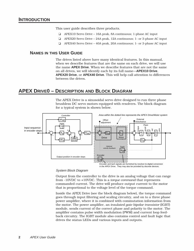
The APEX Drive is a sinusoidal servo drive designed to run three phasebrushless DC servo motors equipped with resolvers. The block diagramfor a typical system is shown below.
Input sequence in encoder steps +
–
+
+ +Kp
sKωƒ
Kis
Controller
sKdα
(s+α)
Kda
Output position in encoder steps
Encoder and tach signals are furnished by resolver-to-digital conversion in the APEX Drive. They may also be provided by discrete devices.
Offset adjustment
Encoder
KΘ
Kω
TachOptional velocity feedback
Drive+
+
-
++Kt
Motor
Gm
External Disturbance
Plant
torq
ue
acce
l
vel
pos
Kv
1J
1s
1s-
++
Area within the dotted line represents the APEX Drive/Motor system
System Block Diagram
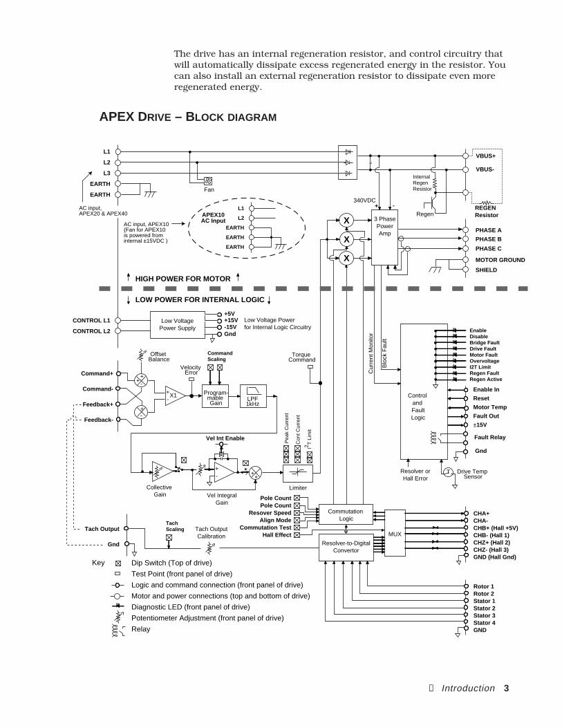
Output from the controller to the drive is an analog voltage that can rangefrom -10VDC to +10VDC. This is a torque command that representscommanded current. The drive will produce output current to the motorthat is proportional to the voltage level of the torque command.
Inside the APEX Drive (see the block diagram below), the torque commandgoes through input filtering and scaling circuitry, and on to a three phasepower amplifier, where it is combined with commutation information fromthe motor. The power amplifier, an insulated gate bipolar transistor (IGBT)module, sends current of the correct phase and polarity to the motor. Theamplifier contains pulse width modulation (PWM) and current loop feed-back circuitry. The IGBT module also contains control and fault logic thatdrives the status LEDs and various inputs and outputs.
➀ Introduction 3
The drive has an internal regeneration resistor, and control circuitry thatwill automatically dissipate excess regenerated energy in the resistor. Youcan also install an external regeneration resistor to dissipate even moreregenerated energy.
APEX DRIVE – BLOCK DIAGRAM
LPF1kHz
Collective Gain
+-
LimiterVel Integral
Gain
VBUS+
VBUS-
REGEN Resistor
Internal Regen ResistorFan
X
X
X 3 PhasePowerAmp PHASE A
PHASE C
PHASE B
MOTOR GROUND
HIGH POWER FOR MOTOR
LOW POWER FOR INTERNAL LOGIC
SHIELD
340VDC
Commutation Logic
Resolver-to-DigitalConvertor
Low VoltagePower Supply
Low Voltage Powerfor Internal Logic Circuitry
MUX
CHA+CHA-CHB+ (Hall +5V)CHB- (Hall 1)CHZ+ (Hall 2)CHZ- (Hall 3)GND (Hall Gnd)
Rotor 1Rotor 2Stator 1Stator 2Stator 3Stator 4GND
Pole CountPole Count
Resover SpeedAlign Mode
Commutation TestHall Effect
Vel Int Enable
Torque Command
-+
+-
Command+
Command-
Feedback+
Feedback-
+
Offset Balance
+-X1
Velocity Error
Program-mable Gain
CommandScaling
TachScaling
Regen+ -
CONTROL L1
CONTROL L2
Control and FaultLogic
Blo
ck F
ault
Cur
rent
Mon
itor
Enable In
Reset
Motor Temp
Fault Out
±15V
TResolver orHall Error
EnableDisableBridge FaultDrive FaultMotor FaultOvervoltageI2T LimitRegen FaultRegen Active
Drive Temp Sensor
Fault Relay
Gnd
Tach OutputCalibration
Tach Output
Gnd
Con
t Cur
rent
Pea
k C
urre
nt
I2 T L
imit
++
Key Dip Switch (Top of drive)
Test Point (front panel of drive)
Logic and command connection (front panel of drive)
Motor and power connections (top and bottom of drive)
Diagnostic LED (front panel of drive)
Potentiometer Adjustment (front panel of drive)
Relay
+5V+15V-15VGnd
L1
L2
L3
EARTH
EARTH
AC input, APEX10(Fan for APEX10 is powered from internal ±15VDC )
AC input, APEX20 & APEX40 APEX10
AC Input
L1
L2
EARTH
EARTH
EARTH
4 APEX User Guide
ADDITIONAL FEATURES
TWO AC POWER INPUTSThe drive has two AC inputs. One provides power for motor current,through the internal high-power three phase amplifier. The other inputprovides power for logic and control, through the internal low-voltage DCpower supply. With these two separate inputs, you can remove powerfrom the motor, but continue to power internal control circuits.
TORQUE MODE OR VELOCITY MODEMost users will operate the drive with a servo controller, such asCompumotor's 6250 Servo Controller. With this type of controller, werecommend operating the drive in torque mode. This provides the bestperformance, and eliminates the need for tuning at the drive.
You can operate the drive in velocity mode if you use a P type controller(as opposed to PID type controller), or if you need to control the velocity ofa spindle with an analog velocity command.
RESOLVER OR HALL EFFECTThe default setup for the Apex drives is to use a resolver forcommuntation. Encoder signals for feedback are also derived from theresolver information; however, a motor with Hall effects and an encodercan be used in place of a motor with a resolver.
DIP SWITCHESThe APEX Drive has a bank of DIP switches located on top of the drive.You can set these switches to configure the drive for your particularapplication.
INPUTS AND OUTPUTSAll input and output signal connections are made on the front panel ofthe drive, through removable screw terminal connectors. The power andmotor connections are separated (top and bottom of the drive) and re-cessed from the front panel for safety.

➀ Introduction 5
COMPUMOTOR SERVO MOTORS
Compumotor sells three models of servo motors with the APEXDr ive .
APEX Series Servo Motors
SM Series Servo Motors
NeoMetric Series Servo Motors
Each model is available in many different sizes. See Chap-ter 4 Hardware Reference for motor specifications and dimen-s ions .
COMPUMOTOR FAMILY OF PRODUCTS
The APEX Drive is completely compatible with Compumotor'sbroad range of single-axis and multi-axis motion controlproducts.

6 APEX User Guide
This page left blank intentionally.

② Installation 7
2Installation
IN THIS CHAPTER
Inspect the shipment
Configure DIP switches
Mount the APEX Drive and motor.
Connect resolver, motor, and controller cables.
Tune the system
C H A P T E R TWO
8 APEX User Guide
INSTALLATION OVERVIEW
This chapter contains information you need to install your APEX Drive.Sections in the chapter are presented in the following order:
• Inspect the Shipment• Set DIP Switches• Mount the Drive• Mount the Motor• Connect the Resolver Cable• Connect the Motor Cable• Connect AC Power• Adjust the Offset Balance potentiometer• Connect the Drive to the Controller• Connect the Encoder to the Controller• Test the System—read the encoder, and turn the motor• Connect the Motor to the Load• Tune the System
To install your drive, complete each section in the order presented.
INSPECT THE SHIPMENT
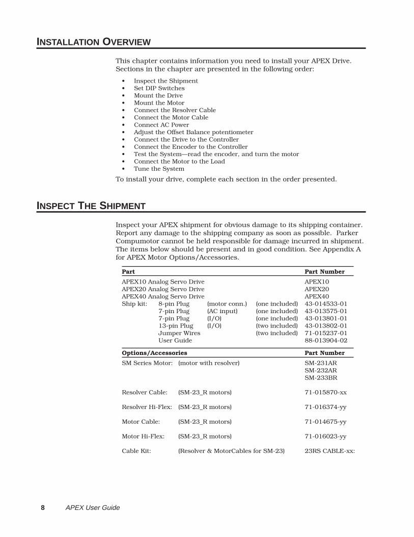
Inspect your APEX shipment for obvious damage to its shipping container.Report any damage to the shipping company as soon as possible. ParkerCompumotor cannot be held responsible for damage incurred in shipment.The items below should be present and in good condition. See Appendix Afor APEX Motor Options/Accessories.
Part Part Number
APEX10 Analog Servo Drive APEX10APEX20 Analog Servo Drive APEX20APEX40 Analog Servo Drive APEX40Ship kit: 8-pin Plug (motor conn.) (one included) 43-014533-01
7-pin Plug (AC input) (one included) 43-013575-017-pin Plug (I/O) (one included) 43-013801-0113-pin Plug (I/O) (two included) 43-013802-01Jumper Wires (two included) 71-015237-01User Guide 88-013904-02
Options/Accessories Part Number
SM Series Motor: (motor with resolver) SM-231ARSM-232ARSM-233BR
Resolver Cable: (SM-23_R motors) 71-015870-xx
Resolver Hi-Flex: (SM-23_R motors) 71-016374-yy
Motor Cable: (SM-23_R motors) 71-014675-yy
Motor Hi-Flex: (SM-23_R motors) 71-016023-yy
Cable Kit: (Resolver & MotorCables for SM-23) 23RS CABLE-xx:
② Installation 9
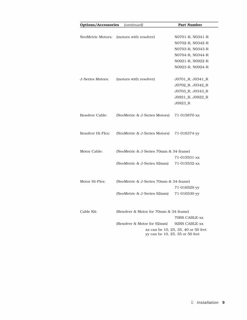
Options/Accessories (continued) Part Number
NeoMetric Motors: (motors with resolver) N0701-R, N0341-R
N0702-R, N0342-R
N0703-R, N0343-R
N0704-R, N0344-R
N0921-R, N0922-R
N0923-R, N0924-R
J-Series Motors: (motors with resolver) J0701_R, J0341_R
J0702_R, J0342_R
J0703_R, J0343_R
J0921_R, J0922_R
J0923_R
Resolver Cable: (NeoMetric & J-Series Motors) 71-015870-xx
Resolver Hi-Flex: (NeoMetric & J-Series Motors) 71-016374-yy
Motor Cable: (NeoMetric & J-Series 70mm & 34-frame)
71-015531-xx
(NeoMetric & J-Series 92mm) 71-015532-xx
Motor Hi-Flex: (NeoMetric & J-Series 70mm & 34-frame)
71-016529-yy
(NeoMetric & J-Series 92mm) 71-016530-yy
Cable Kit: (Resolver & Motor for 70mm & 34-frame)
70RS CABLE-xx
(Resolver & Motor for 92mm) 92RS CABLE-xx
xx can be 10, 25, 35, 40 or 50 feetyy can be 10, 25, 35 or 50 feet
10 APEX User Guide
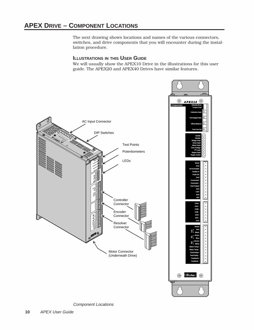
APEX DRIVE – COMPONENT LOCATIONS
The next drawing shows locations and names of the various connectors,switches, and drive components that you will encounter during the instal-lation procedure.
ILLUSTRATIONS IN THIS USER GUIDEWe will usually show the APEX10 Drive in the illustrations for this userguide. The APEX20 and APEX40 Drives have similar features.
A P E X 1 0
Compumotor
Velocity Erro
r
Velocity Erro
r
Torque Cmd
Torque Cmd
Collectiv
e Gain
Collectiv
e Gain
Vel Integral G
ain
Vel Integral G
ain
Offset B
alance
Tach Out Cal
Tach Out Cal
Enable
Disable
Bridge Fault
Bridge Fault
Drive Fault
Motor Fault
Over Volta
ge
I2T Lim
it
Regen Fault
Regen Active
Reset
Gnd
Vel Int E
nable
Enable In
Enable In
Fault Out
Gnd
Command+
Command -
Command -
Tach Output
Gnd
+15V
Gnd
-15V
CHA+
CHA -
CHB+
CHB -
CHZ+
CHZ -
Gnd
Shield
Red
Black
Green
Blue
Brown
White
Motor Temp+
Motor Temp -
Motor Temp -
Fault Relay+
Fault Relay -
Fault Relay -
Feedback+
Feedback -
Feedback -
DA
NG
ER
HIGH VOLTAGE
L1L2
Earth
Earth
Earth
Control L
1
Control L
2
Ref
Sin
Cos
Potentiometers
Test Points
LEDs
Motor Connector(Underneath Drive)
AC Input Connector
DIP Switches
Controller Connector
Encoder Connector
Resolver Connector
A P E X 1 0Compumotor Velocity Error
Torque Cmd
Collective Gain
Vel Integral GainVel Integral Gain
Offset Balance
Tach Out Cal
Enable
Disable
Bridge Fault
Drive Fault
Motor Fault
Over Voltage
I2T Limit
Regen Fault
Regen Active
Reset
Gnd
Vel Int Enable
Enable In
Fault Out
Gnd
Command+
Command -
Tach Output
Gnd
+15V
Gnd
-15V
CHA+
CHA -
CHB+
CHB -
CHZ+
CHZ -
Gnd
Shield
Red
Black
Green
Blue
Brown
White
Motor Temp+
Motor Temp -Motor Temp -
Fault Relay+
Fault Relay -Fault Relay -
Feedback+
Feedback -
Ref
Sin
Cos
Component Locations
② Installation 11
BENCH TEST – GETTING STARTED QUICKLY
To familiarize yourself with the APEX Drive, you may wish to perform abench test before you permanently install the drive. To do so, read thisinstallation chapter, and perform the procedures that are necessary toproduce motion:
• Set DIP Switches• Connect the Resolver Cable• Connect the Motor Cable• Connect AC Power• Adjust the Offset Balance potentiometer• Connect the Drive to the Controller• Connect the Encoder to the Controller• Test the system—read the encoder, and turn the motor
Read, but do not perform, permanent installation procedures:
• Mount the Drive• Mount the Motor• Connect the Motor to the Load• Tune the System
When you are ready to permanently install your drive, you can completethese last four procedures.
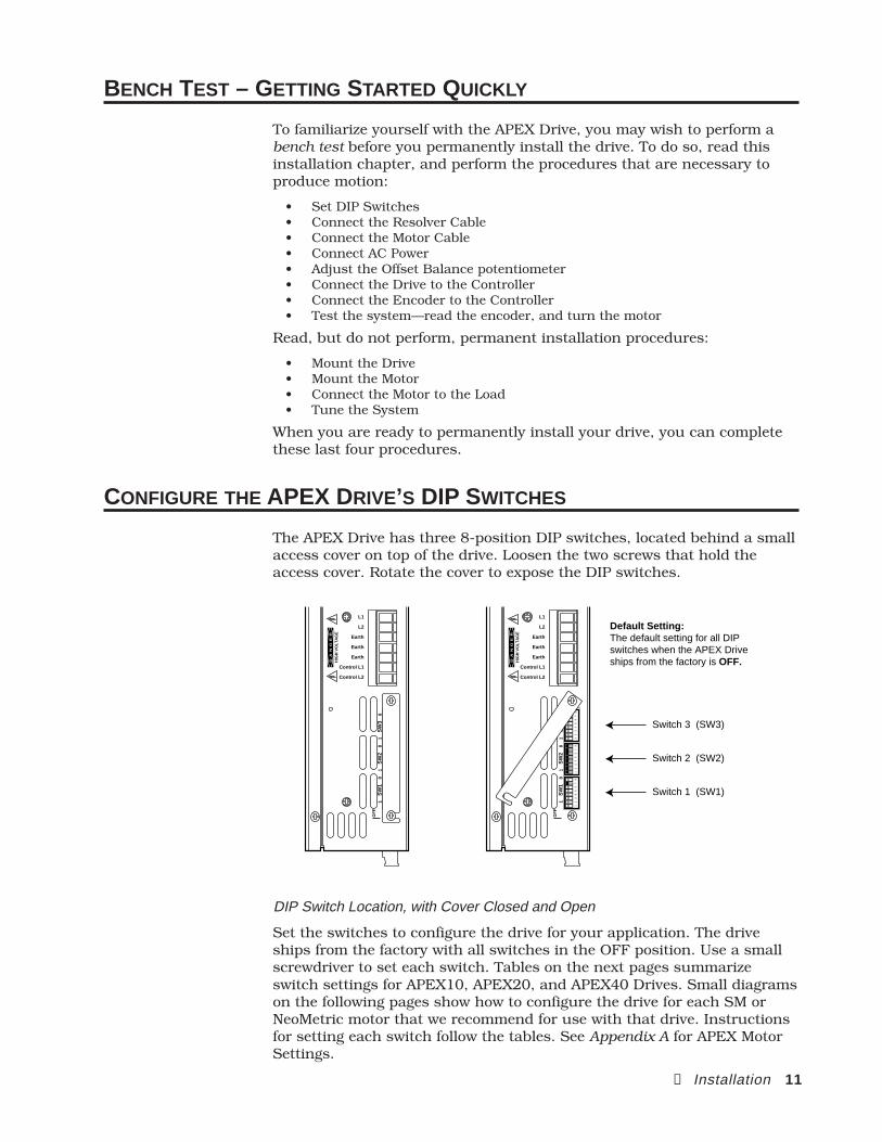
CONFIGURE THE APEX DRIVE’S DIP SWITCHES
The APEX Drive has three 8-position DIP switches, located behind a smallaccess cover on top of the drive. Loosen the two screws that hold theaccess cover. Rotate the cover to expose the DIP switches.
12
34
56
78
12
34
56
78
12
34
56
78
DA
NG
ER
L1
L2
Earth
Earth
Earth
Control L1
Control L2
HIG
H V
OLT
AG
E
OFF
18
SW
11
8S
W2
18
SW
3
12
34
56
78
12
34
56
78
12
34
56
78
DA
NG
ER
L1
L2
Earth
Earth
Earth
Control L1
Control L2
HIG
H V
OLT
AG
E
OFF
18
SW
11
8S
W2
18
SW
3
Default Setting:The default setting for all DIP switches when the APEX Drive ships from the factory is OFF.
Switch 1 (SW1)
Switch 2 (SW2)
Switch 3 (SW3)
DIP Switch Location, with Cover Closed and Open
Set the switches to configure the drive for your application. The driveships from the factory with all switches in the OFF position. Use a smallscrewdriver to set each switch. Tables on the next pages summarizeswitch settings for APEX10, APEX20, and APEX40 Drives. Small diagramson the following pages show how to configure the drive for each SM orNeoMetric motor that we recommend for use with that drive. Instructionsfor setting each switch follow the tables. See Appendix A for APEX MotorSettings.
12 APEX User Guide
OFF
1
1 2 3 4 5 6 7 8
ON
OFF
2
ON
OFF
3
ON
OFF
4
ON
OFF
5
ON
OFF OFF
6 7
OFF ONON OFFON ON
OFF
8
ON
VELOCITY INTEGRATOR
ALIGNMENT MODE
COMMUTATION TEST MODE
HALL SELECT
TACH SCALING
COMMAND INPUT SCALING
COLLECTIVE GAIN
NoYes
NoYes
NoYes
Resolver Mode Hall Mode
One speed resolver (1V = 1,000 RPM with a one speed resolver) Two speed resolver (1V = 1,000 RPM with a two speed resolver)
10V = 16.0 amps10V = 12.0 amps10V = 8.0 amps10V = 7.0 amps
OffOn
OFF
1 2 3 4 5 6 7 8
ONOFFONOFFONOFFON
CONTINUOUS CURRENT (peak of sine wave)
PEAK CURRENT
MOTOR THERMAL TIME CONSTANT
1.8 amps 2.6 3.4 4.0 5.0 6.0 7.0 8.0
6.5 amps 7.5 9.511.012.514.0 15.016.0
2 minutes 4 8 10
OFFOFF
OFF
4 5
ONONON
OFFON
OFFOFF
OFF
7 8
ONONON
OFFON
OFFOFF
OFF
31 2
OFFOFFOFF
ONON
ONON
OFFOFF
ONON
ONON
OFFONOFFONOFFONOFFON
OFFOFF
OFF
64 5
OFFOFFOFF
ONON
OFFONOFFON
OFF
87
OFFONON
ONON
OFFOFF
ONON
ONON
OFF
6
ON
RESERVED
POLE PAIR NUMBER
RESOLVER SPEED
CURRENT LOOP COMPENSATION (motor inductance)
Off
2 3ReservedReserved
1 2
with 120VAC Input: with 240VAC Input:1 – 2 mH Not Applicable2 – 5 mH 5 – 20 mH 5 – 60 mH 20 – 60 mH Reserved
OFF
3
REGEN FAULT
HALL DEGREES
EnableDisable
120∞ Hall motor 60∞ Hall motor
OFFON
OFFON
1
2
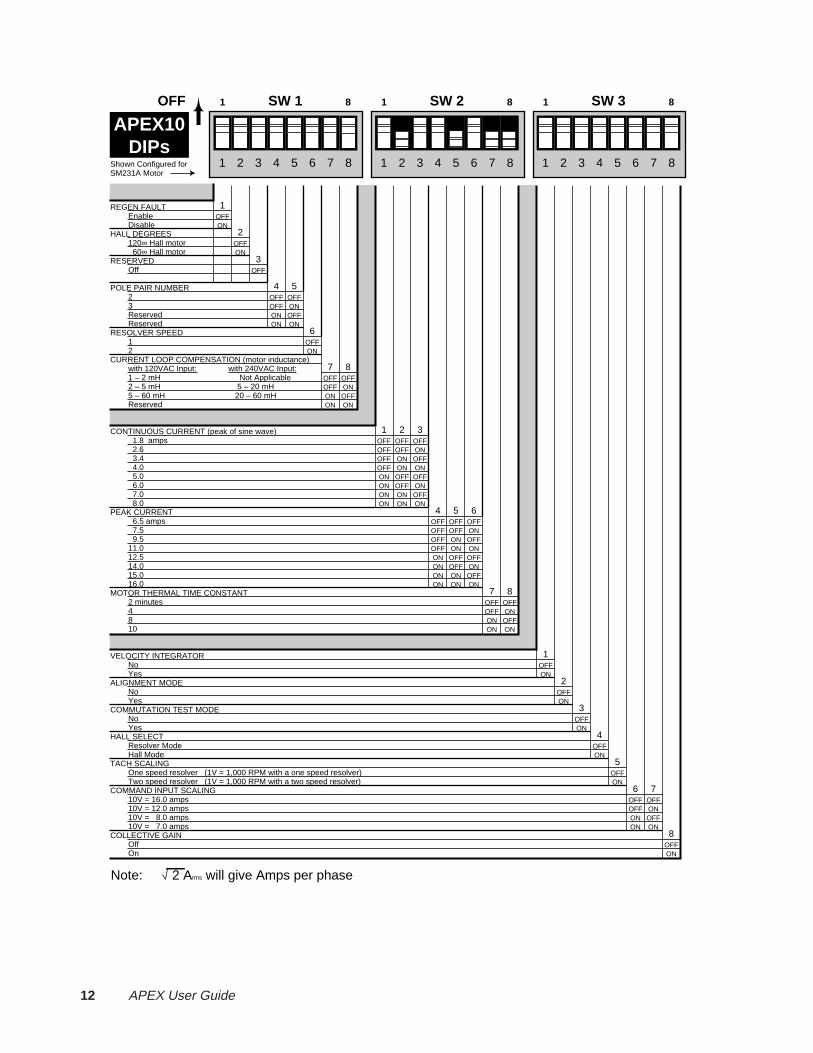
SW 11 8 SW 21 8 SW 31 8OFF
APEX10DIPs
1 2 3 4 5 6 7 8Shown Configured forSM231A Motor
Note: 2 Arms will give Amps per phase
② Installation 13
SM231AR 1 2 3 4 5 6 7 81 2 3 4 5 6 7 81 2 3 4 5 6 7 8
SW 11 8 SW 21 8 SW 31 8OFF
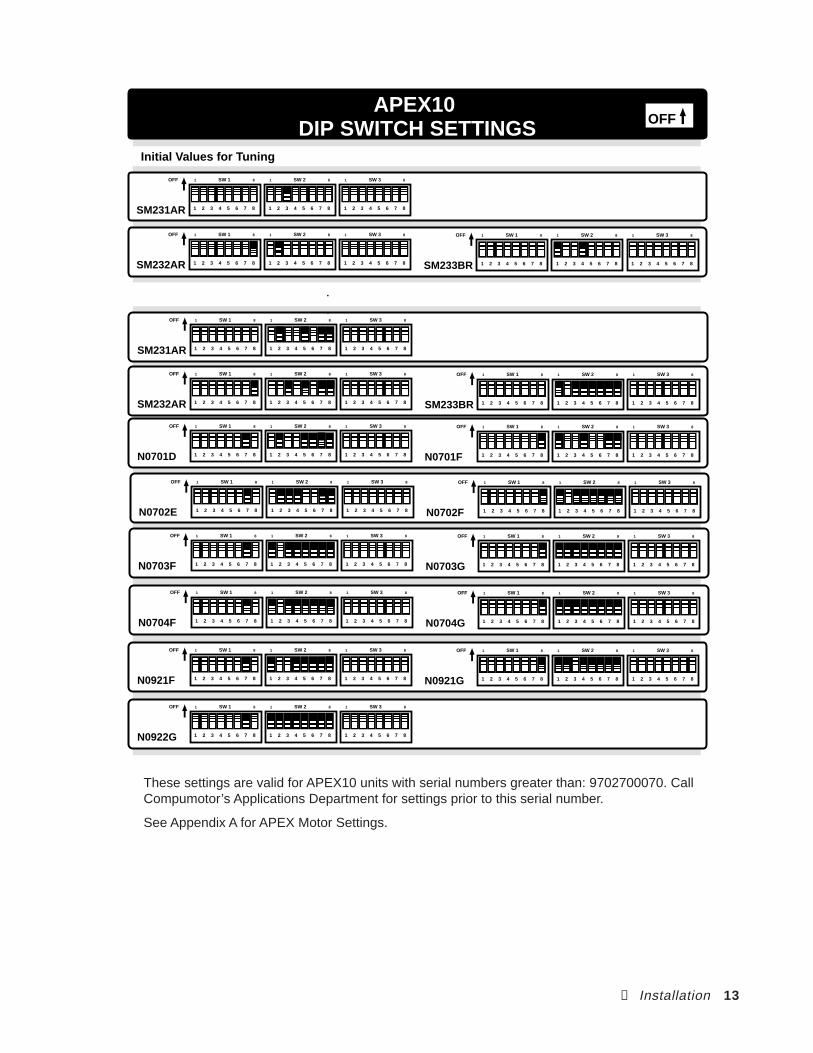
APEX10 DIP SWITCH SETTINGS OFF
SM233BR 1 2 3 4 5 6 7 81 2 3 4 5 6 7 81 2 3 4 5 6 7 8
SW 11 8 SW 21 8 SW 31 8OFF
SM232AR 1 2 3 4 5 6 7 81 2 3 4 5 6 7 81 2 3 4 5 6 7 8
SW 11 8 SW 21 8 SW 31 8OFF
N0701D 1 2 3 4 5 6 7 81 2 3 4 5 6 7 81 2 3 4 5 6 7 8
SW 11 8 SW 21 8 SW 31 8OFF
N0701F 1 2 3 4 5 6 7 81 2 3 4 5 6 7 81 2 3 4 5 6 7 8
SW 11 8 SW 21 8 SW 31 8OFF
N0702E 1 2 3 4 5 6 7 81 2 3 4 5 6 7 81 2 3 4 5 6 7 8
SW 11 8 SW 21 8 SW 31 8OFF
N0702F 1 2 3 4 5 6 7 81 2 3 4 5 6 7 81 2 3 4 5 6 7 8
SW 11 8 SW 21 8 SW 31 8OFF
N0703F 1 2 3 4 5 6 7 81 2 3 4 5 6 7 81 2 3 4 5 6 7 8
SW 11 8 SW 21 8 SW 31 8OFF
N0703G 1 2 3 4 5 6 7 81 2 3 4 5 6 7 81 2 3 4 5 6 7 8
SW 11 8 SW 21 8 SW 31 8OFF
N0704F 1 2 3 4 5 6 7 81 2 3 4 5 6 7 81 2 3 4 5 6 7 8
SW 11 8 SW 21 8 SW 31 8OFF
N0704G 1 2 3 4 5 6 7 81 2 3 4 5 6 7 81 2 3 4 5 6 7 8
SW 11 8 SW 21 8 SW 31 8OFF
SM231AR 1 2 3 4 5 6 7 81 2 3 4 5 6 7 81 2 3 4 5 6 7 8
SW 11 8 SW 21 8 SW 31 8OFF
SM233BR 1 2 3 4 5 6 7 81 2 3 4 5 6 7 81 2 3 4 5 6 7 8
SW 11 8 SW 21 8 SW 31 8OFF
SM232AR 1 2 3 4 5 6 7 81 2 3 4 5 6 7 81 2 3 4 5 6 7 8
SW 11 8 SW 21 8 SW 31 8OFF
Initial Values for Tuning
N0921F 1 2 3 4 5 6 7 81 2 3 4 5 6 7 81 2 3 4 5 6 7 8
SW 11 8 SW 21 8 SW 31 8OFF
N0921G 1 2 3 4 5 6 7 81 2 3 4 5 6 7 81 2 3 4 5 6 7 8
SW 11 8 SW 21 8 SW 31 8OFF
N0922G 1 2 3 4 5 6 7 81 2 3 4 5 6 7 81 2 3 4 5 6 7 8
SW 11 8 SW 21 8 SW 31 8OFF
These settings are valid for APEX10 units with serial numbers greater than: 9702700070. CallCompumotor’s Applications Department for settings prior to this serial number.
See Appendix A for APEX Motor Settings.
14 APEX User Guide
OFF
1
1 2 3 4 5 6 7 8
ON
OFF
2
ON
OFF
3
ON
OFF
4
ON
OFF
5
ON
OFF OFF
6 7
OFF ONON OFFON ON
OFF
8
ON
VELOCITY INTEGRATOR
ALIGNMENT MODE
COMMUTATION TEST MODE
HALL SELECT
TACH SCALING
COMMAND INPUT SCALING
COLLECTIVE GAIN
NoYes
NoYes
NoYes
Resolver Mode Hall Mode
One speed resolver (1V = 1,000 RPM with a one speed resolver) Two speed resolver (1V = 1,000 RPM with a two speed resolver)
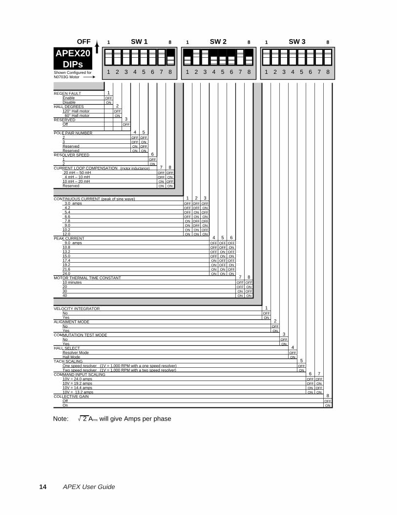
10V = 24.0 amps 10V = 19.2 amps10V = 14.4 amps10V = 13.2 amps
OffOn
OFF
1 2 3 4 5 6 7 8
ONOFFONOFFONOFFON
CONTINUOUS CURRENT (peak of sine wave)
PEAK CURRENT
MOTOR THERMAL TIME CONSTANT
3.0 amps 4.2 5.4 6.6 7.8 9.0 10.212.0
9.0 amps10.813.215.017.419.221.624.0
10 minutes 203040
OFFOFF
OFF
4 5
ONONON
OFFON
OFFOFF
OFF
7 8
ONONON
OFFON
OFFOFF
OFF
31 2
OFFOFFOFF
ONON
ONON
OFFOFF
ONON
ONON
OFFONOFFONOFFONOFFON
OFFOFF
OFF
64 5
OFFOFFOFF
ONON
OFFONOFFON
OFF
87
OFFONON
ONON
OFFOFF
ONON
ONON
OFF
6
ON
RESERVED
POLE PAIR NUMBER
RESOLVER SPEED
CURRENT LOOP COMPENSATION
Off
2 3ReservedReserved
1 2
20 mH – 50 mH 4 mH – 10 mH 10 mH – 20 mHReserved
OFF
3
REGEN FAULT
HALL DEGREES
EnableDisable
120° Hall motor 60° Hall motor
OFFON
OFFON
1
2
SW 11 8 SW 21 8 SW 31 8OFF
Shown Configured forN0703G Motor
APEX20DIPs
1 2 3 4 5 6 7 8
(motor inductance)
Note: 2 Arms will give Amps per phase

② Installation 15
APEX20DIP SWITCH SETTINGS OFF
N0922G 1 2 3 4 5 6 7 81 2 3 4 5 6 7 81 2 3 4 5 6 7 8
SW 11 8 SW 21 8 SW 31 8OFF
N0922J 1 2 3 4 5 6 7 81 2 3 4 5 6 7 81 2 3 4 5 6 7 8
SW 11 8 SW 21 8 SW 31 8OFF
N0923H 1 2 3 4 5 6 7 81 2 3 4 5 6 7 81 2 3 4 5 6 7 8
SW 11 8 SW 21 8 SW 31 8OFF
N0924J 1 2 3 4 5 6 7 81 2 3 4 5 6 7 81 2 3 4 5 6 7 8
SW 11 8 SW 21 8 SW 31 8OFF
N0703G 1 2 3 4 5 6 7 81 2 3 4 5 6 7 81 2 3 4 5 6 7 8
SW 11 8 SW 21 8 SW 31 8OFF
N0921G 1 2 3 4 5 6 7 81 2 3 4 5 6 7 81 2 3 4 5 6 7 8
SW 11 8 SW 21 8 SW 31 8OFF
N0704G 1 2 3 4 5 6 7 81 2 3 4 5 6 7 81 2 3 4 5 6 7 8
SW 11 8 SW 21 8 SW 31 8OFF
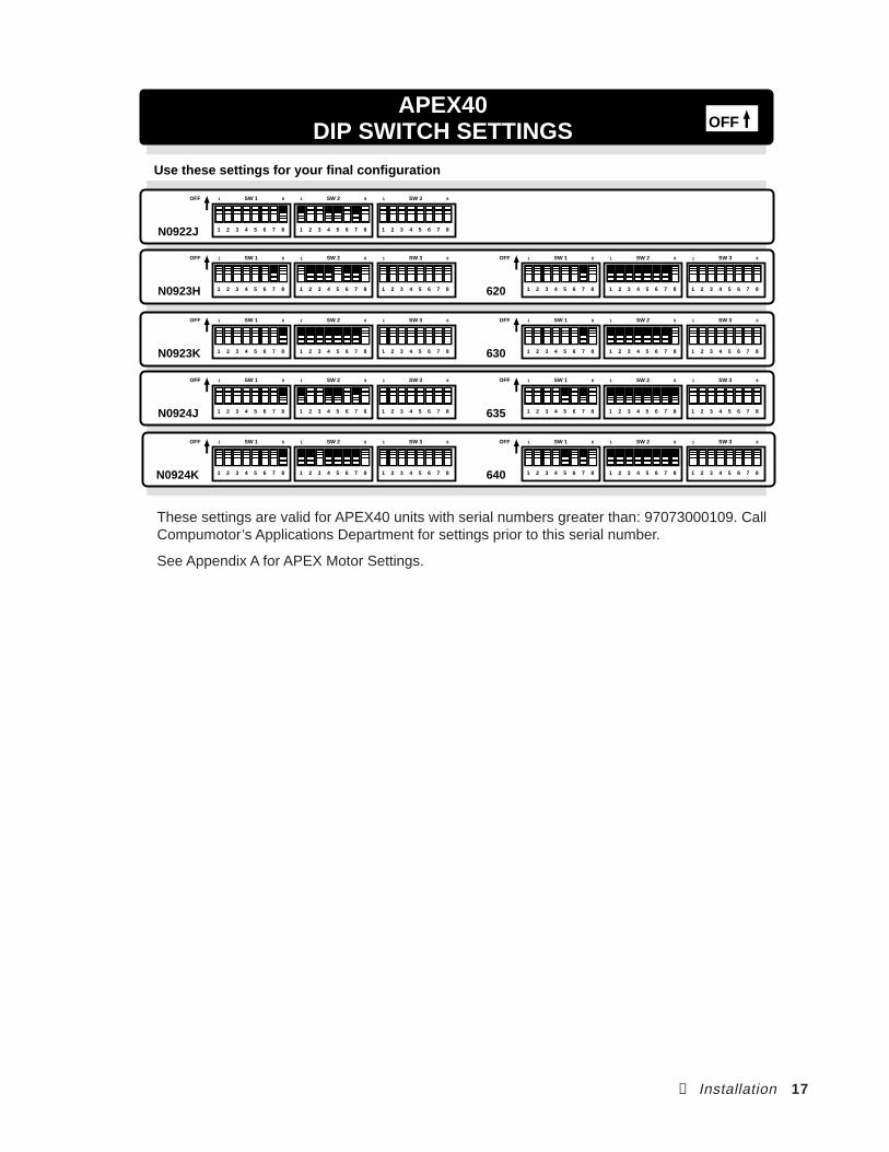
Use these settings for your final configuration
These settings are valid for APEX20 units with serial numbers greater than: 97073000109. CallCompumotor’s Applications Department for settings prior to this serial number.
See Appendix A for APEX Motor Settings.

16 APEX User Guide
OFF
1
1 2 3 4 5 6 7 8
ON
OFF
2
ON
OFF
3
ON
OFF
4
ON
OFF
5
ON
OFF OFF
6 7
OFF ONON OFFON ON
OFF
8
ON
VELOCITY INTEGRATOR
ALIGNMENT MODE
COMMUTATION TEST MODE
HALL SELECT
TACH SCALING
COMMAND INPUT SCALING
COLLECTIVE GAIN
NoYes
NoYes
NoYes
Resolver Mode Hall Mode
One speed resolver (1V = 1,000 RPM with a one speed resolver) Two speed resolver (1V = 1,000 RPM with a two speed resolver)
10V = 40.0 amps 10V = 32.0 amps10V = 25.0 amps10v = 22.0 amps
OffOn
OFF
1 2 3 4 5 6 7 8
ONOFFONOFFONOFFON
CONTINUOUS CURRENT (peak of sine wave)
PEAK CURRENT
MOTOR THERMAL TIME CONSTANT
5.0 amps 7.0 9.011.013.015.017.020.0
15.0 amps18.022.025.029.032.036.040.0
10 minutes20 30 40
OFFOFF
OFF
4 5
ONONON
OFFON
OFFOFF
OFF
7 8
ONONON
OFFON
OFFOFF
OFF
31 2
OFFOFFOFF
ONON
ONON
OFFOFF
ONON
ONON
OFFONOFFONOFFONOFFON
OFFOFF
OFF
64 5
OFFOFFOFF
ONON
OFFONOFFON
OFF
87
OFFONON
ONON
OFFOFF
ONON
ONON
OFF
6
ON(motor inductance)
RESERVED
POLE PAIR NUMBER
RESOLVER SPEED
CURRENT LOOP COMPENSATION
Off
2 3 ReservedReserved
1 2
20 mH – 50 mH 4 mH – 10 mH 10 mH – 20 mH Reserved
OFF
3
REGEN FAULT
HALL DEGREES
EnableDisable
120° Hall motor 60° Hall motor
OFFON
OFFON
1
2
SW 11 8 SW 21 8 SW 31 8OFF
Shown Configured forN0922J Motor
APEX40DIPs
1 2 3 4 5 6 7 8
Note: 2 Arms will give Amps per phase
② Installation 17
APEX40DIP SWITCH SETTINGS OFF
N0924K 1 2 3 4 5 6 7 81 2 3 4 5 6 7 81 2 3 4 5 6 7 8
SW 11 8 SW 21 8 SW 31 8OFF
620 1 2 3 4 5 6 7 81 2 3 4 5 6 7 81 2 3 4 5 6 7 8
SW 11 8 SW 21 8 SW 31 8OFF
640 1 2 3 4 5 6 7 81 2 3 4 5 6 7 81 2 3 4 5 6 7 8
SW 11 8 SW 21 8 SW 31 8OFF
N0922J 1 2 3 4 5 6 7 81 2 3 4 5 6 7 81 2 3 4 5 6 7 8
SW 11 8 SW 21 8 SW 31 8OFF
N0924J 1 2 3 4 5 6 7 81 2 3 4 5 6 7 81 2 3 4 5 6 7 8
SW 11 8 SW 21 8 SW 31 8OFF
N0923K 1 2 3 4 5 6 7 81 2 3 4 5 6 7 81 2 3 4 5 6 7 8
SW 11 8 SW 21 8 SW 31 8OFF
Use these settings for your final configuration
N0923H 1 2 3 4 5 6 7 81 2 3 4 5 6 7 81 2 3 4 5 6 7 8
SW 11 8 SW 21 8 SW 31 8OFF
635 1 2 3 4 5 6 7 81 2 3 4 5 6 7 81 2 3 4 5 6 7 8
SW 11 8 SW 21 8 SW 31 8OFF
630 1 2 3 4 5 6 7 81 2 3 4 5 6 7 81 2 3 4 5 6 7 8
SW 11 8 SW 21 8 SW 31 8OFF
These settings are valid for APEX40 units with serial numbers greater than: 97073000109. CallCompumotor’s Applications Department for settings prior to this serial number.
See Appendix A for APEX Motor Settings.
18 APEX User Guide
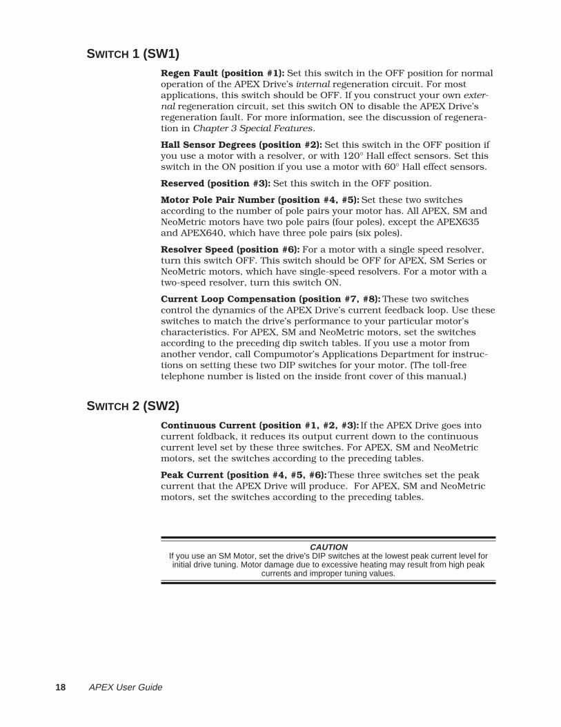
SWITCH 1 (SW1)Regen Fault (position #1): Set this switch in the OFF position for normaloperation of the APEX Drive’s internal regeneration circuit. For mostapplications, this switch should be OFF. If you construct your own exter-nal regeneration circuit, set this switch ON to disable the APEX Drive’sregeneration fault. For more information, see the discussion of regenera-tion in Chapter 3 Special Features.
Hall Sensor Degrees (position #2): Set this switch in the OFF position ifyou use a motor with a resolver, or with 120° Hall effect sensors. Set thisswitch in the ON position if you use a motor with 60° Hall effect sensors.
Reserved (position #3): Set this switch in the OFF position.
Motor Pole Pair Number (position #4, #5): Set these two switchesaccording to the number of pole pairs your motor has. All APEX, SM andNeoMetric motors have two pole pairs (four poles), except the APEX635and APEX640, which have three pole pairs (six poles).
Resolver Speed (position #6): For a motor with a single speed resolver,turn this switch OFF. This switch should be OFF for APEX, SM Series orNeoMetric motors, which have single-speed resolvers. For a motor with atwo-speed resolver, turn this switch ON.
Current Loop Compensation (position #7, #8): These two switchescontrol the dynamics of the APEX Drive’s current feedback loop. Use theseswitches to match the drive’s performance to your particular motor’scharacteristics. For APEX, SM and NeoMetric motors, set the switchesaccording to the preceding dip switch tables. If you use a motor fromanother vendor, call Compumotor’s Applications Department for instruc-tions on setting these two DIP switches for your motor. (The toll-freetelephone number is listed on the inside front cover of this manual.)
SWITCH 2 (SW2)Continuous Current (position #1, #2, #3): If the APEX Drive goes intocurrent foldback, it reduces its output current down to the continuouscurrent level set by these three switches. For APEX, SM and NeoMetricmotors, set the switches according to the preceding tables.
Peak Current (position #4, #5, #6): These three switches set the peakcurrent that the APEX Drive will produce. For APEX, SM and NeoMetricmotors, set the switches according to the preceding tables.
CAUTIONIf you use an SM Motor, set the drive's DIP switches at the lowest peak current level forinitial drive tuning. Motor damage due to excessive heating may result from high peak
currents and improper tuning values.
② Installation 19
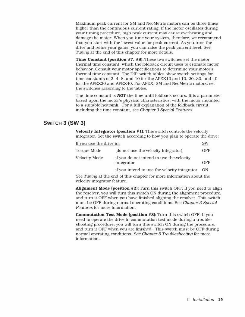
Maximum peak current for SM and NeoMetric motors can be three timeshigher than the continuous current rating. If the motor oscillates duringyour tuning procedure, high peak current may cause overheating anddamage the motor. When you tune your system, therefore, we recommendthat you start with the lowest value for peak current. As you tune thedrive and refine your gains, you can raise the peak current level. SeeTuning at the end of this chapter for more details.
Time Constant (position #7, #8): These two switches set the motorthermal time constant, which the foldback circuit uses to estimate motorbehavior. Consult your motor specifications to determine your motor’sthermal time constant. The DIP switch tables show switch settings fortime constants of 2, 4, 8, and 10 for the APEX10 and 10, 20, 30, and 40for the APEX20 and APEX40. For APEX, SM and NeoMetric motors, setthe switches according to the tables.
The time constant is NOT the time until foldback occurs. It is a parameterbased upon the motor’s physical characteristics, with the motor mountedto a suitable heatsink. For a full explanation of the foldback circuit,including the time constant, see Chapter 3 Special Features.
SWITCH 3 (SW 3)Velocity Integrator (position #1): This switch controls the velocityintegrator. Set the switch according to how you plan to operate the drive:
If you use the drive in: SW
Torque Mode (do not use the velocity integrator) OFF
Velocity Mode if you do not intend to use the velocityintegrator OFF
if you intend to use the velocity integrator ON
See Tuning at the end of this chapter for more information about thevelocity integrator feature.
Alignment Mode (position #2): Turn this switch OFF. If you need to alignthe resolver, you will turn this switch ON during the alignment procedure,and turn it OFF when you have finished aligning the resolver. This switchmust be OFF during normal operating conditions. See Chapter 3 SpecialFeatures for more information.
Commutation Test Mode (position #3): Turn this switch OFF. If youneed to operate the drive in commutation test mode during a trouble-shooting procedure, you will turn this switch ON during the procedure,and turn it OFF when you are finished. This switch must be OFF duringnormal operating conditions. See Chapter 5 Troubleshooting for moreinformation.

20 APEX User Guide
Hall Select (position #4): Turn this switch OFF if your motor has aresolver. This switch should be OFF for APEX, SM and NeoMetric Seriesservo motors, which have resolvers. Turn this switch ON if your motor hasHall effect sensors instead of a resolver.
Tachometer Scaling (position #5): This switch scales the drive's tachom-eter output. If you use a motor that has a single speed resolver, turn thisswitch OFF to scale the tachometer output to equal 1 volt per 1,000 rpm.This switch should be OFF for APEX, SM or NeoMetric Series servo mo-tors, which have single-speed resolvers. If you use a motor that has a two-speed resolver, turn this switch ON. This will adjust gains of the internalcircuitry, so that the tachometer output is scaled to equal 1 volt per 1,000rpm for two speed resolvers.
Command Input Scaling (position #6, #7): Use these two switches toscale the relationship (full-scale) between command input voltage andmotor output current. For full current, with a 10V input corresponding tomaximum peak output current, both switches should be OFF. Set theswitches according to the preceding DIP switch tables for other currents.
Collective Gain (position #8): This switch controls the collective gainfunction. Set the switch according to how you plan to operate the drive:
If you use the drive in: SW
Torque Mode collective gain is not used in torque mode OFF
Velocity Mode collective gain is used in velocity mode ON
See Tuning later in this chapter for more information about collective gain.
MOUNT THE APEX DRIVE
The APEX Drive should be installed in an enclosure that will protect itfrom atmospheric contaminants such as oil, metallic particles, moisture,and dirt. The National Electrical Manufacturers Association (NEMA) hasestablished standards that define the degree of protection that electricalenclosures provide. Because industrial application environments maycontain airborne contaminants, the enclosure you use should, as a mini-mum, conform to a NEMA TYPE 12 standard.
INSTALLATION PRECAUTIONS
To ensure personal safety and long life of system components, pay specialattention to the following installation precautions.
TEMPERATUREMaximum Ambient Temperature: 50°C (122°F)
Minimum Ambient Temperature: 0°C (32°F)
HUMIDITYMaximum Relative Humidity: 95% (non-condensing)

② Installation 21
LIQUIDSDo not allow liquids or fluids to come into contact with the APEX Drive or itscables.
AIRBORNE CONTAMINANTSThe APEX Drive’s fan provides internal forced air cooling whenever the driveis powered. However, the drive does not have any type of intake air filter.You must protect the drive’s intake air supply from contamination if youoperate the drive in an environment where dust or metallic particles arepresent, or where there may be airborne condensing moisture, solvents, orlubricants.
ELECTRICAL NOISEMinimize the possibility of electrical noise problems before installing theAPEX Drive, rather than attempting to solve such problems after installa-tion. Prevent electrical noise problems by observing the following guidelines:
Do not route high-voltage wires and low-level signals in the sameconduit.
Ensure that all components are properly grounded
Ensure that all wiring is properly shielded
MOUNTING AND GROUNDINGThe APEX Drive’s mounting bracket is notched with keyhole type slots toaccept four screws for flat panel surface mounting. One of the slots—upperright—is unpainted. You can use a star washer between the mounting screwand this slot, to help provide additional electrical grounding between theAPEX Drive and the mounting surface. The drive must also be groundedthrough the Earth terminal on the AC power connector.
22 APEX User Guide
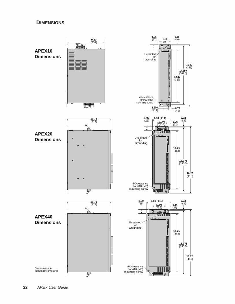
DIMENSIONS
5.88 (149)
3.000(76.2)
1.00(25)
0.33(8.4)
15.375(390.5)
16.25(413)
14.25(362)
1.44(37)
Dimensions in inches (millimeters)
A P E X 4 0
Unpaintedfor
Grounding
4.50 (114)2.000 (50.8)
4X clearancefor #10 (M5)
mounting screw
1.00(25)
0.33(8.4)
15.375(390.5)
16.25(413)
14.25(362)
1.25(32)
A P E X 2 0
Unpainted for
Grounding
4X clearancefor #10 (M5)
mounting screw
3.00(76)
1.06(27)
12.89(327)
14.250(362.0)
15.00(381)
0.18(4.6)
1.500(38.1)
4x clearancefor #10 (M5)
mounting screw
Unpaintedfor
grounding
0.75(19)
A P E X 1 0
10.75(273)
9.20(234)
10.75(273)
APEX10Dimensions
APEX20Dimensions
APEX40Dimensions
② Installation 23
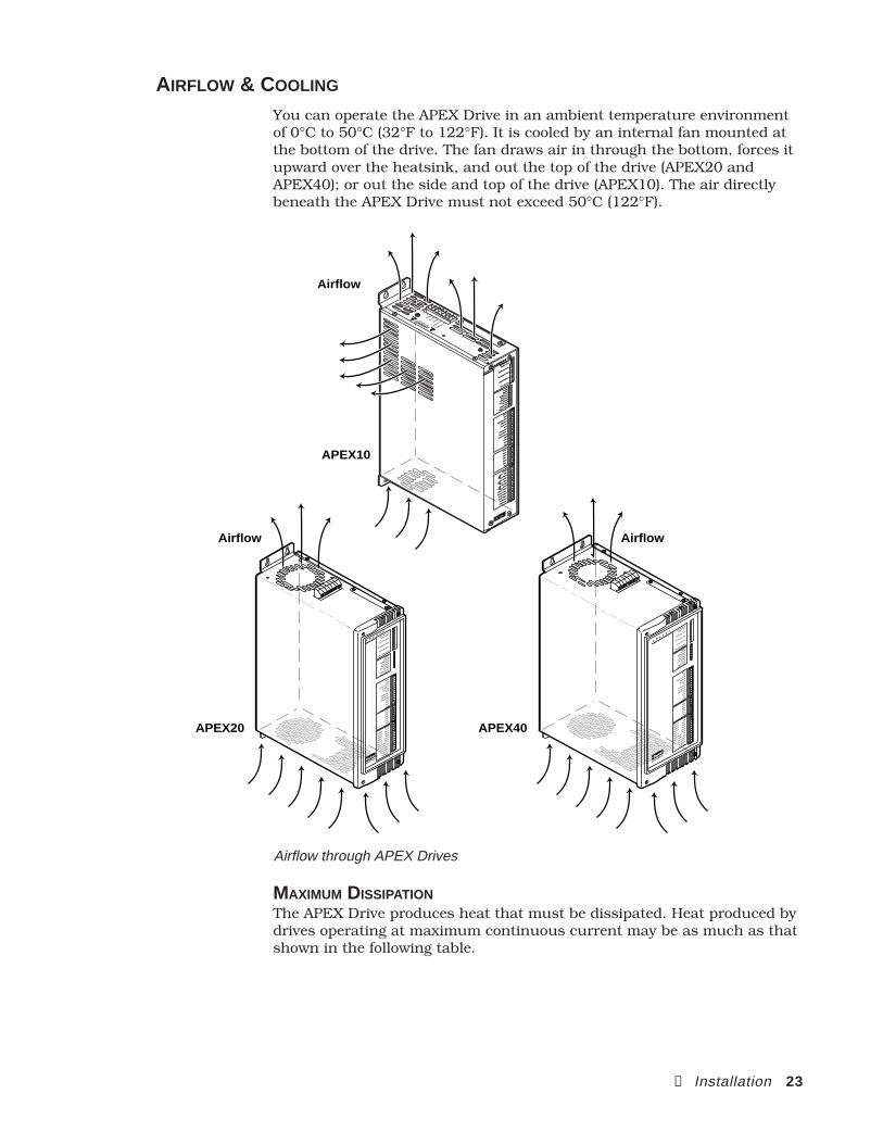
AIRFLOW & COOLING
You can operate the APEX Drive in an ambient temperature environmentof 0°C to 50°C (32°F to 122°F). It is cooled by an internal fan mounted atthe bottom of the drive. The fan draws air in through the bottom, forces itupward over the heatsink, and out the top of the drive (APEX20 andAPEX40); or out the side and top of the drive (APEX10). The air directlybeneath the APEX Drive must not exceed 50°C (122°F).
Compumotor
AP
EX
2 0
Velocity Error
Torque Cmd
Collective Gain
Vel Integral G
ain
Offset B
alance
Tach Output Cal
Enable
Disable
Bridge Fault
Drive Fault
Motor Fault
Over Voltage
I2t Limit
Regen Fault
Regen Active
CHA+
CHA–
CHB+
CHB–
CHZ+
CHZ–
Gnd
Shield
Red
Black
Green
Blue
Brown
White
Yel
Org
Fault Relay+
Fault Relay–
Feedback+
Feedback–
Stator 1
Stator 2
Stator 3
Stator 4
Rotor 1
Rotor 2
Motor Temp+
Motor Temp-
Reset
Gnd
Vel Int E
nable
Enable In
Fault Out
Gnd
Command+
Command-
Tach Output
Gnd
+15V
Gnd
-15V
APEX20 APEX40
AirflowAirflow
A P E X 1 0
Compumotor
Velocity Erro
r
Velocity Erro
r
Torque Cmd
Collectiv
e Gain
Collectiv
e Gain
Vel Integral G
ain
Vel Integral G
ain
Offset B
alance
Tach Out Cal
Tach Out Cal
Enable
Disable
Bridge Fault
Drive Fault
Motor Fault
Over Volta
ge
I2T Lim
it
Regen Fault
Regen Active
Reset
Gnd
Vel Int E
nable
Enable In
Fault Out
Gnd
Command+
Command -
Command -
Tach Output
Gnd
+15V
Gnd
-15V
CHA+
CHA -
CHB+
CHB -
CHZ+
CHZ -
Gnd
Shield
Red
Black
Green
Blue
Brown
White
Motor Temp+
Motor Temp -
Motor Temp -
Fault Relay+
Fault Relay -
Fault Relay -
Feedback+
Feedback -
Feedback -
DA
NG
ER
HIGH VOLTAGE
L1L2
Earth
Earth
Earth
Control L
1
Control L
2
Ref
Sin
Cos
APEX10
Airflow
AP
EX
4 0 Velocity Erro
r
Torque Cmd
Collective Gain
Vel Integral G
ain
Offset B
alance
Tach Output Cal
Enable
Disable
Bridge Fault
Drive Fault
Motor Fault
Over Volta
ge
I2t Lim
it
Regen Fault
Regen Active
CHA+
CHA–
CHB+
CHB–
CHZ+
CHZ–
Gnd
Shield
Red
Black
Green
Blue
Brown
White
Yel
Org
Fault Relay+
Fault Relay–
Feedback+
Feedback–
Stator 1
Stator 2
Stator 3
Stator 4
Rotor 1
Rotor 2
Motor Temp+
Motor Temp–
Compumotor
Reset
Gnd
Vel Int E
nable
Enable In
Fault Out
Gnd
Command+
Command-
Tach Output
Gnd
+15V
Gnd
-15V
Airflow through APEX Drives
MAXIMUM DISSIPATIONThe APEX Drive produces heat that must be dissipated. Heat produced bydrives operating at maximum continuous current may be as much as thatshown in the following table.
24 APEX User Guide
Continuous MaximumDrive Current (amps) Dissipation (watts)APEX10 8 A 100 WAPEX20 12 A 150 WAPEX40 20 A 200 W
The actual dissipation will vary depending on the application duty cycle,motor size, and load inertia.
INTERNAL TEMPERATURE SENSORSThe APEX Drive has two temperature sensors. One is mounted on thecontrol board, near the microprocessor. The other is mounted within thepower bridge. If the internal temperature is too high—perhaps because ofblocked airflow, a fan that has stopped working, or external ambienttemperatures higher than 50°C (122°F)—one of these sensors will shutdown the drive. When the sensor on the control board shuts down thedrive, it also illuminates the Drive Fault LED. When the sensor on thepower bridge shuts down the drive, it illuminates the Bridge Fault LED.
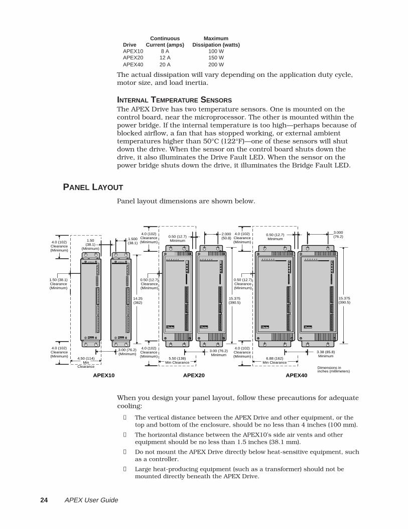
PANEL LAYOUT
Panel layout dimensions are shown below.
Dimensions in inches (millimeters)
0.50 (12.7)Minimum
3.38 (85.8)Minimum
3.000(76.2)
4.0 (102)Clearance(Minimum)
A P E X 4 0
15.375(390.5)
4.0 (102)Clearance(Minimum)
0.50 (12.7)Clearance(Minimum)
6.88 (162)Min Clearance
APEX40
A P E X 4 0
1.50(38.1)
(Minimum)
3.00 (76.2)(Minimum)
1.500(38.1)
4.0 (102)Clearance(Minimum)
14.25(362)
4.0 (102)Clearance(Minimum)
1.50 (38.1)Clearance(Minimum)
4.50 (114)Min
Clearance
APEX10
A P E X 1 0 A P E X 1 0
0.50 (12.7)Minimum
3.00 (76.2)Minimum
2.000(50.8)
4.0 (102)Clearance(Minimum)
15.375(390.5)
4.0 (102)Clearance(Minimum)
0.50 (12.7)Clearance(Minimum)
5.50 (138)Min Clearance
A P E X 2 0 A P E X 2 0
APEX20
When you design your panel layout, follow these precautions for adequatecooling:
➀ The vertical distance between the APEX Drive and other equipment, or thetop and bottom of the enclosure, should be no less than 4 inches (100 mm).
➁ The horizontal distance between the APEX10’s side air vents and otherequipment should be no less than 1.5 inches (38.1 mm).
➂ Do not mount the APEX Drive directly below heat-sensitive equipment, suchas a controller.
➃ Large heat-producing equipment (such as a transformer) should not bemounted directly beneath the APEX Drive.

② Installation 25
MOUNT THE MOTOR
The following guidelines present important points about motor mountingand its effect on performance. For dimensions and specifications forAPEX, SM and NeoMetric Series servo motors, see Chapter 4 HardwareReference.
WarningImproper motor mounting can jeopardize personal safety and reduce system performance.
Servo motors used with the APEX Drive can produce large torques andhigh accelerations. These forces can shear shafts and mounting hardwareif the mounting is not adequate. High accelerations can produce shocksand vibrations that require much heavier hardware than would be ex-pected for static loads of the same magnitude.
The motor, under certain move profiles, can produce low-frequency vibra-tions in the mounting structure. These vibrations can cause metal fatiguein structural members. Have a mechanical engineer check the machinedesign to ensure that the mounting structure is adequate.
CAUTIONModifying or machining the motor shaft will void the motor warranty. Contact a Compumotor
Applications Engineer (800-358-9070) about shaft modifications as a custom product.
Servo motors should be mounted by bolting the motor’s face flange to asuitable support. Foot mount or cradle configurations are not recom-mended because the motor’s torque is not evenly distributed around themotor case.
MOTOR HEATSINKING
Performance of a servo motor is limited by the amount of current that canflow in the motor’s coils without causing the motor to overheat. Most ofthe heat in a brushless servo motor is dissipated in the stator—the outershell of the motor. The primary pathway through which you can removethe heat is through the motor’s mounting flange. Therefore, mount themotor with its flange in contact with a suitable heatsink.
Current foldback (I2T Limit) settings and motor specifications assume thatthe motor is mounted to an aluminum plate of the following dimensions:
SM Series Motors NeoMetric
10" x 10" x 0.25" aluminum 10" x 10" x 0.25" aluminum
(250 x 250 x 6.3 mm) (250 x 250 x 6.3 mm)
To get rated performance in your application, you must mount the motorto a heatsink of at least the same thermal capability as those listed above.Mounting the motor to a smaller heatsink may result in decreased perfor-mance and a shorter service life. Conversely, mounting the motor to alarger heatsink can result in enhanced performance.
WARNINGThe motor case can become very hot, even under normal operating conditions. Do not
touch or contact the motor. Keep heat-sensitive equipment away from the motor.
26 APEX User Guide
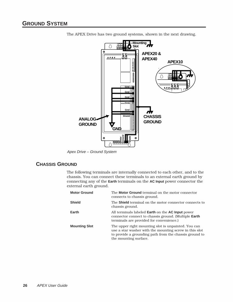
GROUND SYSTEM
The APEX Drive has two ground systems, shown in the next drawing.
A P E X
Gnd
Gnd Gnd Gnd
Shield
L3
L2
L1
Ear
tE
art
MountingSlot
Mot
orG
roun
d
Shi
eld
ANALOGGROUND
CHASSISGROUND
APEX10
APEX20 & APEX40
GND
A P E X 1 0
L2
L1
Ear
tE
art
Ear
t
Gnd
Apex Drive – Ground System
CHASSIS GROUND
The following terminals are internally connected to each other, and to thechassis. You can connect these terminals to an external earth ground byconnecting any of the Earth terminals on the AC Input power connector theexternal earth ground.
Motor Ground The Motor Ground terminal on the motor connectorconnects to chassis ground.
Shield The Shield terminal on the motor connector connects tochassis ground.
Earth All terminals labeled Earth on the AC Input powerconnector connect to chassis ground. (Multiple Earthterminals are provided for convenience.)
Mounting Slot The upper right mounting slot is unpainted. You canuse a star washer with the mounting screw in this slotto provide a grounding path from the chassis ground tothe mounting surface.
② Installation 27
CIRCUIT GROUND (GND)The following terminals are internally connected to each other. They arenot connected to the chassis ground.
Gnd All terminals labeled Gnd are internally connected.
Shield The Shield terminal on the resolver connector is internallyconnected to the Gnd terminals.
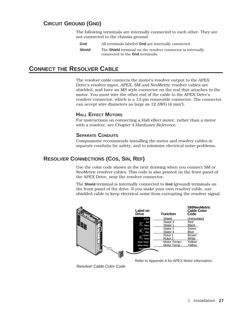
CONNECT THE RESOLVER CABLE
The resolver cable connects the motor’s resolver output to the APEXDrive’s resolver input. APEX, SM and NeoMetric resolver cables areshielded, and have an MS style connector on the end that attaches to themotor. You must wire the other end of the cable to the APEX Drive’sresolver connector, which is a 13-pin removable connector. The connectorcan accept wire diameters as large as 12 AWG (4 mm2).
HALL EFFECT MOTORSFor instructions on connecting a Hall effect motor, rather than a motorwith a resolver, see Chapter 4 Hardware Reference.
SEPARATE CONDUITSCompumotor recommends installing the motor and resolver cables inseparate conduits for safety, and to minimize electrical noise problems.
RESOLVER CONNECTIONS (COS, SIN, REF)Use the color code shown in the next drawing when you connect SM orNeoMetric resolver cables. This code is also printed on the front panel ofthe APEX Drive, near the resolver connector.
The Shield terminal is internally connected to Gnd (ground) terminals onthe front panel of the drive. If you make your own resolver cable, useshielded cable to keep electrical noise from corrupting the resolver signal.
Shield
Red
Black
Green
Blue
Brown
White
Motor Temp+
Motor Temp -
Fault Relay+
ShieldStator 3Stator 1Stator 2Stator 4Rotor 1Rotor 2Motor Temp+Motor Temp -
FunctionLabel onDrive
Ref
Sin
Cos
UninsulatedRedBlackGreenBlueBrownWhiteYellowYellow
SM/NeoMetricCable ColorCode
A P E X 1 0
A P E X 1 0
Compumotor
Compumotor
Velocity Erro
r
Velocity Erro
r
Torque Cmd
Torque Cmd
Collective G
ain
Collective G
ain
Vel Integral G
ain
Vel Integral G
ain
Offset B
alance
Offset B
alance
Tach O
ut Cal
Tach O
ut Cal
EnableEnable
Disable
Disable
Bridge Fault
Bridge Fault
Drive Fault
Drive Fault
Motor Fault
Motor Fault
Over V
oltage
Over V
oltage
I2T Lim
it
T Limit
Regen Fault
Regen Fault
Regen Active
Regen Active
Reset
Reset
GndGnd
Vel Int E
nable
Vel Int E
nable
Enable In
Enable In
Fault Out
Fault Out
GndGnd
Command+
Command+
Command -
Command -
Tach O
utput
Tach O
utput
GndGnd
+15V
GndGnd
-15V
CHA+CHA+
CHA -CHA -
CHB+CHB+
CHB -CHB -
CHZ+CHZ+
CHZ -CHZ -
GndGnd
ShieldShield
RedRed
BlackBlack
GreenGreen
BlueBlue
BrownBrown
WhiteWhite
Motor Temp+
Motor Temp+
Motor Temp -
Motor Temp -
Fault Relay+
Fault Relay+
Fault Relay -
Fault Relay -
Feedback+
Feedback -
Feedback -
DA
NG
ER
HIGH VOLTAGE
L1L2
Earth
Earth
Earth
Control L
1
Control L
2
Ref
Ref
Sin
Sin
Cos
Cos
Resolver Connector
Refer to Appendix A for APEX Motor information.
Resolver Cable Color Code
28 APEX User Guide
MOTOR TEMPERATURE (MOTOR TEMP±)To connect your motor's thermostat, follow these instructions:
APEX Motor – connect the yellow wire in the resolver cable to Motor Temp+ .Connect the orange wire to Motor Temp– .
SM Motor – both wires are yellow. Connect one to Motor Temp+ , the other toMotor Temp– .
Other Motors – for motors with normally-closed temperature sensors,connect the sensor’s two wires to Motor Temp– and Motor Temp– .
Motor with no Thermostat – if your motor does not have a thermostat, shortMotor Temp+ and Motor Temp– together by connecting an insulated jumperwire between them. The drive will experience a motor fault if neither athermostat nor a jumper wire is attached to the Motor Temp terminals.
The APEX Drive's motor temperature fault can, in many cases, protect themotor against overheating. Through its Motor Temp+ and Motor Temp–terminals, the drive checks for electrical continuity provided by a nor-mally-closed thermostat mounted on the motor. If the motor overheatsand the thermostat opens, the loss of continuity triggers protection cir-cuitry in the APEX Drive. It will turn off power output to the motor, andilluminate the LED labeled Motor Fault .
The thermostat may not protect the motor in every possible application. Itworks best in cases where the temperature rise occurs slowly over a longperiod of time. In this situation, the thermostat and motor windings willbe at the same temperature. When the windings and thermostat reach thethermostat’s threshold temperature, the thermostat can trigger the over-temperature circuit.
In cases where the temperature rise is caused by a flow of continuouspeak current—an unstable or oscillating motor during tuning, or a me-chanical jam, for example—the winding temperature may rise much morequickly than the thermostat temperature rises. In this situation, thewindings may be damaged from overheating before the thermostat cantrigger the overtemperature circuit.
MOTOR BRAKING (FAULT RELAY±)If the APEX Drive faults, for any reason, the drive will be disabled and themotor will freewheel. (Refer to Chapter 5 Troubleshooting for a list of allfault conditions.) If a freewheeling load is unacceptable, you can use thefault relay terminals, Fault Relay + and Fault Relay– , to control a motorbrake. For complete instructions, see Chapter 3 Special Features.
FEEDBACK ±If you operate the APEX Drive in torque mode, make no connections to theFeedback+ or Feedback– terminals.
If you operate the APEX Drive in velocity mode, connect the Feedbackinput terminals to a tachometer output signal. If you use the APEX Drive’sinternal tachometer:
➀ Connect Tach Output on the controller connector to Feedback+ on theresolver connector.
➁ Connect any of the Gnd (ground) terminals on the controller connector toFeedback– on the resolver connector.
② Installation 29
If you use an external tachometer:
➀ Connect the tachometer’s output to Feedback+ on the resolver connector.
➁ Connect the tachometer’s ground to Feedback– on the resolver connector.
Use twisted pair wire for these connections, to minimize noise problems.
See Chapter 4 Hardware Reference for a schematic diagram of the Feed-back± input terminals.
CONNECT THE MOTOR CABLE
After wiring the connector to the resolver cable, as described above,connect the motor cable to the motor and to the APEX Drive.
CONNECT THE MOTOR CABLE
The motor cable connects the APEX Drive’s power output terminals,located on the bottom of the drive, to the motor’s power input terminals.APEX, SM and NeoMetric motor cables have an MS style connector on theend that attaches to the motor. You must wire the other end of the cableto the APEX Drive’s motor connector, which is an 8-pin removable con-nector located on the bottom of the drive. The connector can accept wirediameters as large as 10 AWG (6 mm2).
SEPARATE CONDUITCompumotor recommends installing the motor and resolver cables inseparate conduits to minimize electrical noise problems, as well as forsafety.
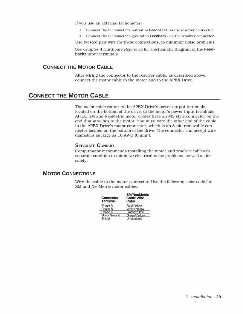
MOTOR CONNECTIONS
Wire the cable to the motor connector. Use the following color code forSM and NeoMetric motor cables.
Phase APhase BPhase CMotor GroundShield
ConnectorTerminal
SM/NeoMetricCable Wire ColorRed/YellowWhite/YellowBlack/YellowGreen/YellowUninsulated
30 APEX User Guide
MOTOR GROUNDINGThe motor cable should have a motor ground wire and also a cable shieldwire. Connect the ground wire to the terminal labeled Motor Ground .Connect the shield wire to the terminal labeled Shield . Inside the drive,the Motor Ground and Shield terminals are connected to each other, andto the Earth terminal on the AC Input power connector. On some APEX orSM cables, the ground wire and shield wire are crimped together when thecables are manufactured. You can insert both cables into the MotorGround terminal.
WARNINGDO NOT OMIT the Motor Ground connection. Internal failure of motor insulation can
place the motor frame at deadly potential if it is not properly grounded. Do not rely solely onmounting bolts for motor grounding.
REGEN RESISTOR
The APEX Drive can dissipate regenerated energy in its internal regenera-tion resistor. If your system must dissipate more energy than the resistoris rated for, use the Regen Resistor terminal to connect an external regen-eration resistor on either an APEX 10 or 40. Refer to Chapter 3 SpecialFeatures for instructions on connecting an external regeneration resistor.
VBUS+, VBUS
–These terminals can connect the high voltage power bus between two ormore APEX Drives. Use these terminals to allow one drive to use thepower another drive produces during regeneration. Refer to Chapter 3Special Features for instructions on using this feature.
CONNECT THE CABLE
After wiring the connector to the cable, attach the motor end of the cableto the motor. Plug the drive end of the cable into the APEX Drive's motorconnector.
WARNINGThe motor connector and cable produce lethal voltages. Never insert or remove the motor
cable with AC power turned on to the APEX.
② Installation 31
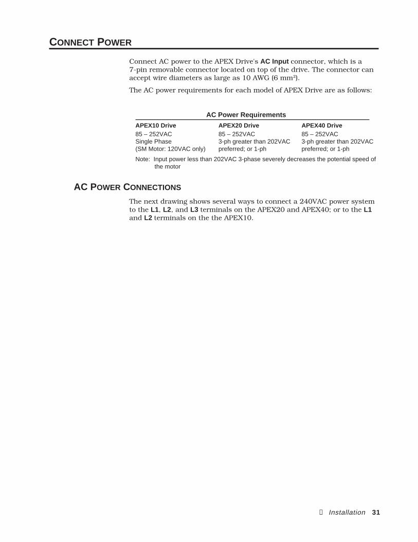
CONNECT POWER
Connect AC power to the APEX Drive's AC Input connector, which is a7-pin removable connector located on top of the drive. The connector canaccept wire diameters as large as 10 AWG (6 mm2).
The AC power requirements for each model of APEX Drive are as follows:
AC Power Requirements
APEX10 Drive APEX20 Drive APEX40 Drive85 – 252VAC 85 – 252VAC 85 – 252VACSingle Phase 3-ph greater than 202VAC 3-ph greater than 202VAC(SM Motor: 120VAC only) preferred; or 1-ph preferred; or 1-ph
Note: Input power less than 202VAC 3-phase severely decreases the potential speed of the motor
AC POWER CONNECTIONS
The next drawing shows several ways to connect a 240VAC power systemto the L1, L2, and L3 terminals on the APEX20 and APEX40; or to the L1and L2 terminals on the the APEX10.

32 APEX User Guide
A
TransformerPrimaries
L1
L2
L3
Earth
L1
L2
L3
Earth
L1
L2
L3
Earth
L1
L2
Earth
TransformerSecondaries
240VAC3 PhaseWye or Delta
240VAC1 Phase
DA
NG
ER
HIG
H V
OL
TA
GE
L1
L2
L3
Earth
Earth
Control L1
Control L2
DA
NG
ER
L1
L2
Earth
Earth
Earth
Control L1
Control L2
HIG
H V
OLT
AG
E
APEX20 and APEX40
APEX10 (use single phase only)
AC Power System – Connections to APEX Drive Input Terminals
Equation for the transformer KVA:
KVA =Pouteff
+ 80W
PF
Pout: power out of the driveeff: drive efficiencyPF: power factor80W: max. power draw of internal power supply
Consult the Compumotor Applications Department for more information.
② Installation 33
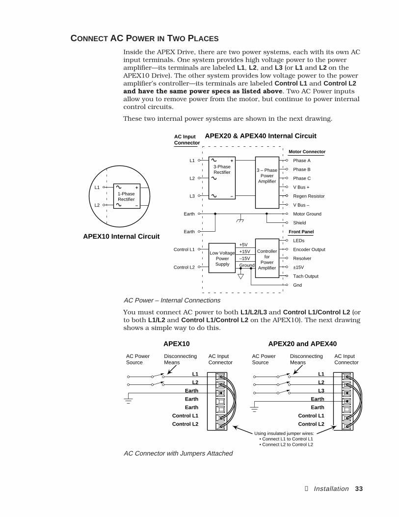
CONNECT AC POWER IN TWO PLACES
Inside the APEX Drive, there are two power systems, each with its own ACinput terminals. One system provides high voltage power to the poweramplifier—its terminals are labeled L1, L2, and L3 (or L1 and L2 on theAPEX10 Drive). The other system provides low voltage power to the poweramplifier’s controller—its terminals are labeled Control L1 and Control L2and have the same power specs as listed above. Two AC Power inputsallow you to remove power from the motor, but continue to power internalcontrol circuits.
These two internal power systems are shown in the next drawing.
1-PhaseRectifier
+
–
L1
L2
APEX20 & APEX40 Internal Circuit
Motor Connector
Front Panel
AC InputConnector
3-PhaseRectifier
+
–
Low VoltagePowerSupply
Controllerfor
PowerAmplifier
+5V
+15V
–15V
Ground
V Bus +
Regen Resistor
V Bus –
Phase A
Phase B
Phase C
±15V
Tach Output
Gnd
LEDs
Encoder Output
Resolver
Motor Ground
Shield
L1
L2
Earth
L3
Earth
3 – PhasePower
Amplifier
Control L1
Control L2
APEX10 Internal Circuit
AC Power – Internal Connections
You must connect AC power to both L1/L2/L3 and Control L1/Control L2 (orto both L1/L2 and Control L1/Control L2 on the APEX10). The next drawingshows a simple way to do this.
L1
L2
L3
Earth
Earth
Control L1
Control L2
AC PowerSource
DisconnectingMeans
DisconnectingMeans
AC InputConnector
Using insulated jumper wires: • Connect L1 to Control L1 • Connect L2 to Control L2
L1
L2
Earth
Earth
Earth
Control L1
Control L2
AC PowerSource
AC InputConnector
APEX20 and APEX40APEX10
AC Connector with Jumpers Attached
34 APEX User Guide
Follow these steps in making connections:
1. Connect your AC input lines to L1, L2 and L3 on the AC input con-nector (L1 and L2 on the APEX10).
2. Using insulated wire jumpers (provided in the ship kit), connect L1 toControl L1 , and connect L2 to Control L2 .
3. Connect your AC ground to Earth on the AC input connector.
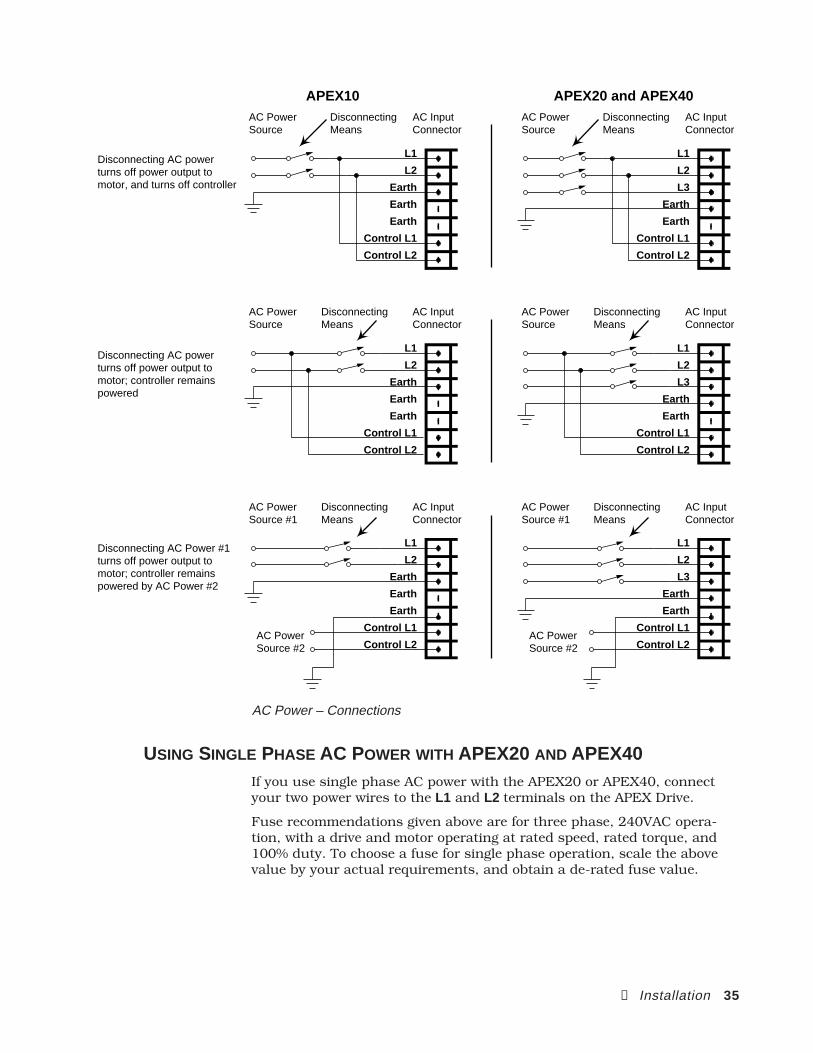
WIRING OPTIONSThe diagram below illustrates options for connecting AC power.
• If you want to completely shut down the drive when you disconnect ACpower, follow the top connection diagram. (This is a schematic versionof the previous drawing.) Use insulated wire jumpers (provided in theship kit) to connect L1 to Control L1 , and to connect L2 to Control L2 .
• If you want to shut down power to the motor when you disconnect ACpower, but keep the amplifier controller energized, follow the middleconnection diagram. This shows that Control L1 and Control L2 areconnected to the AC power source before the disconnecting means.
• If you want to use separate AC power sources for L1/L2 and Control L1/Control L2 , follow the bottom connection diagram. For example, youcan connect 240VAC and a disconnecting means to L1 and L2, andconnect 120VAC to Control L1 and Control L2 .
② Installation 35
L1
L2
L3
Earth
Earth
Control L1
Control L2
AC PowerSource
DisconnectingMeans
AC InputConnector
L1
L2
L3
Earth
Earth
Control L1
Control L2
AC PowerSource
AC InputConnector
L1
L2
L3
Earth
Earth
Control L1
Control L2
AC PowerSource #1
AC PowerSource #2
AC PowerSource #2
AC InputConnector
L1
L2
Earth
Earth
Earth
Control L1
Control L2
AC PowerSource
DisconnectingMeans
AC InputConnector
DisconnectingMeans
L1
L2
Earth
Earth
Earth
Control L1
Control L2
AC PowerSource
AC InputConnector
DisconnectingMeans
DisconnectingMeans
DisconnectingMeans
L1
L2
Earth
Earth
Earth
Control L1
Control L2
AC PowerSource #1
AC InputConnector
APEX20 and APEX40APEX10
Disconnecting AC power turns off power output to motor, and turns off controller
Disconnecting AC power turns off power output to motor; controller remains powered
Disconnecting AC Power #1 turns off power output to motor; controller remains powered by AC Power #2
AC Power – Connections
USING SINGLE PHASE AC POWER WITH APEX20 AND APEX40If you use single phase AC power with the APEX20 or APEX40, connectyour two power wires to the L1 and L2 terminals on the APEX Drive.
Fuse recommendations given above are for three phase, 240VAC opera-tion, with a drive and motor operating at rated speed, rated torque, and100% duty. To choose a fuse for single phase operation, scale the abovevalue by your actual requirements, and obtain a de-rated fuse value.
36 APEX User Guide
CONNECTING AC GROUND
The terminals labeled Earth are internally connected to the APEX Drive'schassis, and to the Motor Ground and motor Shield terminals. For safety,connect the ground from your AC power system to at least one of theEarth terminals (for convenience, multiple terminals are provided).
WARNINGDO NOT OMIT the AC Ground connection. Be sure the APEX Drive’s chassis is properly
and securely grounded to reduce the chance of electrical shock.
FUSING INFORMATION
The APEX Drive has no internal fuses. For safety purposes, you shouldprovide a fuse in each of the AC input lines. Recommended fuses are:
Fuse Recommendations
APEX10 Drive (240VAC) APEX20 Drive (240VAC) APEX40 Drive (240VAC)250V Slow Blow 250V Slow Blow 250V Slow Blow12 – 15 amp 12 – 15 amp 20 – 25 ampLittelfuse 326-012 Littelfuse 326-012 Littelfuse 326-020or equivalent or equivalent or equivalent
APEX10 Drive (120VAC)125V Slow Blow15 – 25 ampLittelfuse 326-025or equivalent
Also provide a fuse for the Control L1/L2 inputs: 250V Slow Blow
3 ampLittlefuse 326-003 or equivalent
WARNINGThe APEX Drive has no internal fuses. For safety purposes, provide a fuse in each of the
AC input lines.
PLUG IN THE CONNECTOR
After wiring the connector to the cable, plug the cable into the APEXDrive’s input power connector. Do not energize the power at this time.The APEX Drive does not have an ON/OFF switch. You must provide asafe means of energizing AC power to the drive (indicated as “disconnect-ing means” in the previous drawings). Use a safety interlock switch orresettable circuit breaker to conveniently de-energize the drive in anemergency and/or service situation.
WARNINGThe motor connector and cable produce lethal voltages. Never insert or remove the motor
cable with AC power turned on to the APEX Drive.
② Installation 37
ADJUST OFFSET BALANCE
Follow the procedure below to adjust the APEX Drive's offset balancepotentiometer. This procedure also serves as a quick test to verify that allsystem connections made thus far have been done correctly. Because themotor will turn during this procedure, make sure that all components areproperly mounted or supported.
WARNINGEven a small offset can cause the motor to quickly accelerate up to high speeds. Please
use extreme care and be ready to disable the drive if necessary.
Proceed to the appropriate option below—Torque Mode or Velocity Mode—based upon how you intend to use the APEX Drive.
OPTION 1: TORQUE MODE
If you intend to operate your system in torque mode, perform the followingprocedure. The controller and encoder output should be disconnectedfrom the drive; the motor should be disconnected from the load.
➀ Power to the APEX Drive should be OFF when you begin this procedure.
➁ Connect a wire between Enable In and Ground (Gnd ) on the controllerconnector. This shorts the enable input to ground, and enables the APEXDrive when you turn on AC power.
NOTE: The next two steps – ➂ & ➃ – were performed at the factory. If yours is anew APEX Drive, you do not need to perform these two steps—use thedefault factory settings. You can proceed to step ➄.
➂ Turn the Collective Gain and Vel Integral Gain potentiometers at least 15turns counterclockwise. This will ensure that the collective gain and velocityintegral gain functions are turned off.
➃ Center the Offset Balance potentiometer—turn it at least 15 turns clockwise,then back it off approximately 7 1/2 turns counterclockwise, to put it in thecenter of its travel.
➄ Turn on AC power to the APEX Drive.
➅ If the motor shaft is turning, adjust the Offset Balance potentiometer to stopthe shaft from turning. (For smaller motors, the null range may be quitenarrow—it may be difficult to find the exact position where the motor shaftstops completely.)
➆ TEST: Turn the Offset Balance potentiometer clockwise. The motor shaftshould turn clockwise (when viewed from the front of the motor).
➇ TEST: Turn the Offset Balance potentiometer counterclockwise. The motorshaft should turn counterclockwise.
➈ After you have performed these tests, adjust the Offset Balance potentiom-eter to stop the motor shaft from turning.
➉ Turn off AC power; remove the wire between enable input and ground.
Successful completion of these tests verifies that the APEX Drive is config-ured correctly, and that the AC power cable, motor cable, and resolvercable are properly wired. Proceed to Connect a Controller below.
If your motor does not turn, or does not turn in the correct direction,check the DIP switch settings and cable connections, and perform the testprocedure again.
38 APEX User Guide
OPTION 2: VELOCITY MODE
If you intend to operate your system in velocity mode, perform the follow-ing procedure before you connect a controller. The controller and encoderoutput should be disconnected from the drive; the motor should be dis-connected from the load.
➀ Power to the APEX Drive should be OFF when you begin this procedure.
➁ Connect a wire between Enable In and Ground (Gnd ) on the controllerconnector. This shorts the enable input to ground, and will enable the APEXDrive when you turn on the AC power.
NOTE: The next two steps – ➂ & ➃ – were performed at the factory. If yours is anew APEX Drive, you do not need to perform these two steps—use thedefault factory settings. You can proceed to step ➄.
➂ Turn the Collective Gain and Vel Integral Gain potentiometers at least 15turns counterclockwise. This will ensure that the collective gain and velocityintegral gain functions are turned off. (These functions may or may not beturned off on DIP switch #3, positions 1 and 8, depending upon how youconfigured the drive for velocity mode.)
➃ Center the Offset Balance potentiometer—turn it at least 15 turns clockwise,then back it off approximately 7 1/2 turns counterclockwise, to put it in thecenter of its travel.
➄ Connect Tach Output (on the controller connector) to Feedback+ (on theresolver connector). Connect Gnd (next to Tach Output ) to Feedback– . Usetwisted pair wire for these connections, to minimize noise problems.
(Optional: if you are using an external tachometer, connect its output toFeedback+ . Connect its ground to Feedback– . Make no connections to theAPEX Drive’s Tach Output ).
See Chapter 4 Hardware Reference for a schematic drawing of theseterminals.
➅ Turn on AC power to the APEX Drive.
➆ If the motor shaft is turning, adjust the Offset Balance potentiometer to stopthe shaft from turning. (For smaller motors, the null range may be quitenarrow—it may be difficult to find the exact position where the motor shaftstops completely.)
➇ TEST: Turn the Offset Balance potentiometer clockwise. The motor shaftshould turn clockwise (when viewed from the front of the motor).
➈ TEST: Turn the Offset Balance potentiometer counterclockwise. The motorshaft should turn counterclockwise.
➉ After you have performed these tests, adjust the Offset Balance potentiom-eter to stop the motor shaft from turning. Turn off AC power, and removethe wire between enable input and ground.
Successful completion of these tests verifies that the APEX Drive is config-ured correctly, and that the AC power cable, motor cable, and resolvercable are properly wired. Proceed to Connect a Controller below.
If your motor does not turn, or does not turn in the correct direction,check the DIP switch settings and cable connections, and perform the testprocedure again.
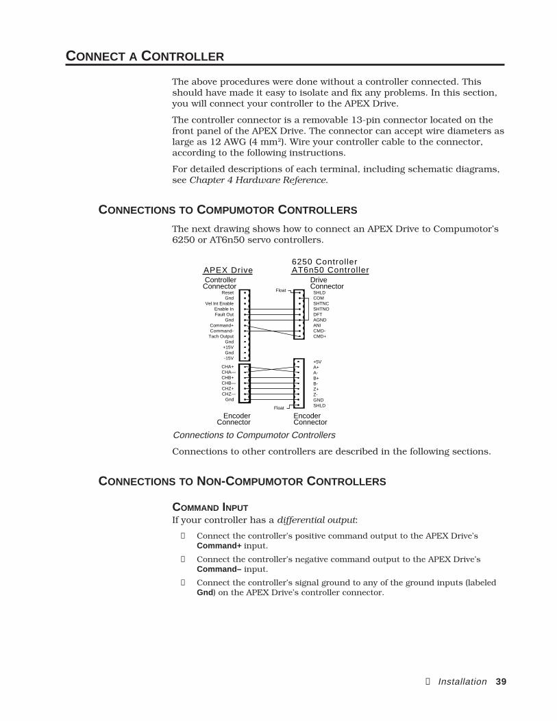
② Installation 39
CONNECT A CONTROLLER
The above procedures were done without a controller connected. Thisshould have made it easy to isolate and fix any problems. In this section,you will connect your controller to the APEX Drive.
The controller connector is a removable 13-pin connector located on thefront panel of the APEX Drive. The connector can accept wire diameters aslarge as 12 AWG (4 mm2). Wire your controller cable to the connector,according to the following instructions.
For detailed descriptions of each terminal, including schematic diagrams,see Chapter 4 Hardware Reference.
CONNECTIONS TO COMPUMOTOR CONTROLLERS
The next drawing shows how to connect an APEX Drive to Compumotor’s6250 or AT6n50 servo controllers.
ResetGnd
Vel Int EnableEnable InFault Out
GndCommand+Command-
Tach OutputGnd
+15VGnd-15V
CHA+CHA—CHB+CHB—CHZ+CHZ—
Gnd
SHLDCOMSHTNCSHTNODFTAGNDANICMD-CMD+
Float
+5VA+A-B+B-Z+Z-GNDSHLDFloat
Controller Connector
DriveConnector
EncoderConnector
EncoderConnector
APEX Drive6250 ControllerAT6n50 Controller
Connections to Compumotor Controllers
Connections to other controllers are described in the following sections.
CONNECTIONS TO NON-COMPUMOTOR CONTROLLERS
COMMAND INPUTIf your controller has a differential output:
➀ Connect the controller’s positive command output to the APEX Drive’sCommand+ input.
➁ Connect the controller’s negative command output to the APEX Drive’sCommand– input.
➂ Connect the controller’s signal ground to any of the ground inputs (labeledGnd ) on the APEX Drive’s controller connector.
40 APEX User Guide
If your controller has a single-ended output:
➀ Connect the controller’s command output to the APEX Drive’s Command+input.
➁ Connect the controller’s signal ground to the APEX Drive’s Command–input.
➂ Connect a wire between the APEX Drive’s Command– input and any of theground inputs (labeled Gnd ) on the APEX Drive’s controller connector. Thiswill reference the Command– input to ground.
If your controller has isolated outputs: some controllers have isolatedcommand outputs, and may require a voltage source to power theiroutputs. The APEX Drive has ±15V available to power isolated outputs ona controller.
➀ Connect the APEX Drive’s ±15V outputs to your controller’s ±15V inputs.
➁ Connect your controller’s single-ended or differential outputs to the APEXDrive, as described above.
See Chapter 4 Hardware Reference for a schematic of the command input.
ENABLE INPUTConnect the controller’s enable output to the APEX Drive’s enable input,labeled Enable In . The enable input is active low—this means that when itis connected to ground, the APEX Drive is enabled. Therefore, your con-troller must pull the APEX Drive’s enable input low (0 – 1.0VDC) to enablethe drive. See Chapter 4 Hardware Reference for a schematic of the enableinput.
FAULT OUTPUTConnect the APEX Drive’s fault output, labeled Fault Out , to thecontroller’s fault input. The fault output is active high—under normalconditions, the drive holds the fault output low (0 – 1.0VDC). To signal afault, the drive will let the fault output float. Your controller may need topull up the fault output signal to an appropriate level. See Chapter 4Hardware Reference for a schematic of the fault output.
GROUNDConnect the controller’s signal ground to one of the ground inputs on theAPEX Drive’s controller connector. All of the ground inputs (labeled Gnd)on the front panel of the APEX Drive are connected together internally.They are isolated from the chassis, from Motor Ground , and from Earth onthe AC input connector.
RESET (OPTIONAL)If the controller has a reset output, and you wish to use it, connect it tothe APEX Drive’s reset input (labeled Reset ). The reset input is active low.To reset the APEX Drive’s processor, the controller must pull the resetinput low (less than 1.0V) for at least 20 milliseconds. Reset begins uponrelease of the low level. See Chapter 4 Hardware Reference for a schematicof the reset input.

② Installation 41
CONNECT ENCODER TO CONTROLLER
Connect the APEX Drive’s encoder output to the controller. The encoderconnector is a removable 7-pin connector located on the front panel of theAPEX Drive. The connector can accept wire diameters as large as 12 AWG(4 mm2).
The APEX Drive uses a resolver–to–digital converter to produce its encoderoutputs. Encoder features are:
ENCODER RESOLUTION: 1024 counts per revolution, pre-quadrature4096 counts per revolution, post-quadrature
CLOCKWISE ROTATION: Channel A leads Channel B
COUNTERCLOCKWISE ROTATION: Channel B leads Channel A
See Chapter 4 Hardware Reference for complete encoder specifications.
The encoder on the APEX Drive has the following outputs:
CHA+CHA–CHB+CHB–CHZ+CHZ–
Gnd
Encoder Output
NameCHA+CHA-CHB+CHB-CHZ+CHZ-Gnd
Function:Channel A+Channel A–Channel B+Channel B–Channel Z+Channel Z–Ground
A P E X 1 0
Compumotor
Compumotor
Velocity Error
Velocity Error
Torque Cmd
Torque Cmd
Collective Gain
Collective Gain
Vel Integral G
ain
Vel Integral G
ain
Offset Balance
Offset Balance
Tach Out Cal
Tach Out Cal
Enable
DisableDisable
Bridge Fault
Bridge Fault
Drive Fault
Drive Fault
Motor Fault
Motor Fault
Over Voltage
Over Voltage
I2T Limit
T Limit
Regen Fault
Regen Fault
Regen Active
Regen Active
ResetReset
GndGnd
Vel Int E
nable
Vel Int E
nable
Enable In
Enable In
Fault Out
Fault Out
GndGnd
Command+
Command+
Command -
Command -
Tach Output
Tach Output
GndGnd
+15V+15V
GndGnd
-15V
CHA+CHA+
CHA -CHA -
CHB+CHB+
CHB -CHB -
CHZ+CHZ+
CHZ -CHZ -
GndGnd
ShieldShield
RedRed
BlackBlack
GreenGreen
BlueBlue
BrownBrown
WhiteWhite
Motor Temp+
Motor Temp+
Motor Temp -
Motor Temp -
Fault Relay+
Fault Relay+
Fault Relay -
Fault Relay -
Feedback+
Feedback+
Feedback -
Feedback -
DANGER
HIGH VOLTAGE
L1
L2
Earth
Earth
Earth
Control L
1
Control L
2R
efS
inC
os
Encoder Connector
Connect these outputs to your controller's encoder inputs. If you use aCompumotor controller, see the connection diagram in the previoussection. (See pg. 37: A+ connected to A-; A- connected to A+)
If the motor has Hall Effects instead of a resolver, the Hall Effects connectto the Encoder Output connector, as shown in Chapter 4, and the encoderon the motor goes to the connector.
TEST: ROTATE MOTOR SHAFT
Perform the following steps to verify that the encoder is connectedproperly.
➀ Disable the APEX Drive. (Use your controller to disable the drive, or removethe wire between the enable input and ground on the controller connector.)
➁ Turn on power to the APEX Drive. The drive should power up, but bedisabled. The Disable LED should illuminate to indicate that the drive isdisabled.
➂ Note the encoder position. (Use your controller, or any other method youprefer, to read the encoder position.)
➃ With the motor disconnected from the load, manually rotate the motor shaftclockwise, approximately one revolution. Read the new encoder position.One revolution exactly will produce 4,096 counts, post-quadrature. Yourreading should be approximately near this number, and should be positivefor clockwise rotation.
42 APEX User Guide
If you intend to operate the APEX Drive in torque mode, successfulcompletion of the above procedures verifies that your APEX Drive isconfigured and operating properly in torque mode. You may now proceedto Preliminary Tuning below.
If you intend to operate the APEX Drive in velocity mode, you shouldcalibrate the tachometer, as described immediately below, before tuningyour system.
CALIBRATE TACHOMETER (VELOCITY MODE ONLY)
In the procedures above, you connected the tachometer output (TachOutput on the APEX Drive’s controller connector) to the velocity feedbacksignal, Feedback+ , on the resolver connector. (See "Adjust Offset Balance")
In this procedure, you will adjust two potentiometers on the front panel ofthe APEX Drive—Offset Balance and Tach Out Cal —to precisely calibratethe APEX Drive’s tachometer output.
➀ Energize AC power to the APEX Drive and enable the drive.
➁ Use your controller to command a velocity of zero (ØV input to the drive).Adjust the Offset Balance potentiometer so that motor shaft velocity is zero(the shaft does not turn).
➂ Use your controller to command a positive velocity. Monitor the actual shaftvelocity, and adjust the Tach Out Cal potentiometer so that actual velocitymatches commanded velocity.
EXAMPLE: For a system that will run at a maximum of 4,000 rpm, com-mand a velocity of 4,000 rpm (4.0V command input). As you monitor shaftvelocity, adjust the Tach Out Cal potentiometer so that actual motor shaftvelocity is 4,000 rpm.
If you intend to operate the APEX Drive in velocity mode, successfulcompletion of the above procedures verifies that your APEX Drive isconfigured and operating properly in velocity mode. You may now proceedto Preliminary Tuning, below.
PRELIMINARY TUNING (WITH NO LOAD ATTACHED)
Before you attach the motor to the load, use your controller to performpreliminary tuning on your system. Consult your controller’s user guidefor instructions on how to tune your system with no load attached. Set-ting tuning gains now will ensure that your system behaves predictablywhen you first turn it on with a load attached to the motor.
TUNING WITH SM MOTORS
Maximum peak current for SM motors can be three times higher than thecontinuous current rating. If the motor oscillates during your tuningprocedure, high peak current may cause overheating and damage themotor. When you tune your system, therefore, we recommend that youstart with the lowest value for peak current. As you tune the drive andrefine your gains, you can raise the peak current level. See Tuning at theend of this chapter for more details.
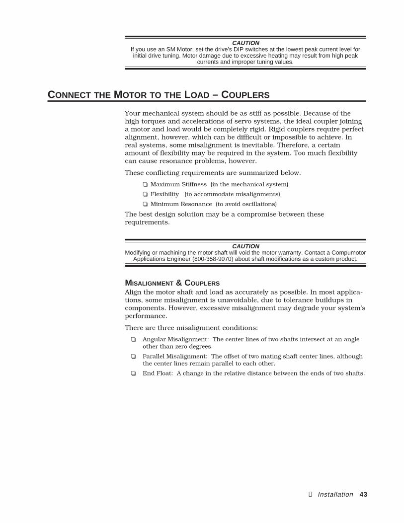
② Installation 43
CAUTIONIf you use an SM Motor, set the drive's DIP switches at the lowest peak current level forinitial drive tuning. Motor damage due to excessive heating may result from high peak
currents and improper tuning values.
CONNECT THE MOTOR TO THE LOAD – COUPLERS
Your mechanical system should be as stiff as possible. Because of thehigh torques and accelerations of servo systems, the ideal coupler joininga motor and load would be completely rigid. Rigid couplers require perfectalignment, however, which can be difficult or impossible to achieve. Inreal systems, some misalignment is inevitable. Therefore, a certainamount of flexibility may be required in the system. Too much flexibilitycan cause resonance problems, however.
These conflicting requirements are summarized below.
Maximum Stiffness (in the mechanical system)
Flexibility (to accommodate misalignments)
Minimum Resonance (to avoid oscillations)
The best design solution may be a compromise between theserequirements.
CAUTIONModifying or machining the motor shaft will void the motor warranty. Contact a Compumotor
Applications Engineer (800-358-9070) about shaft modifications as a custom product.
MISALIGNMENT & COUPLERSAlign the motor shaft and load as accurately as possible. In most applica-tions, some misalignment is unavoidable, due to tolerance buildups incomponents. However, excessive misalignment may degrade your system’sperformance.
There are three misalignment conditions:
Angular Misalignment: The center lines of two shafts intersect at an angleother than zero degrees.
Parallel Misalignment: The offset of two mating shaft center lines, althoughthe center lines remain parallel to each other.
End Float: A change in the relative distance between the ends of two shafts.
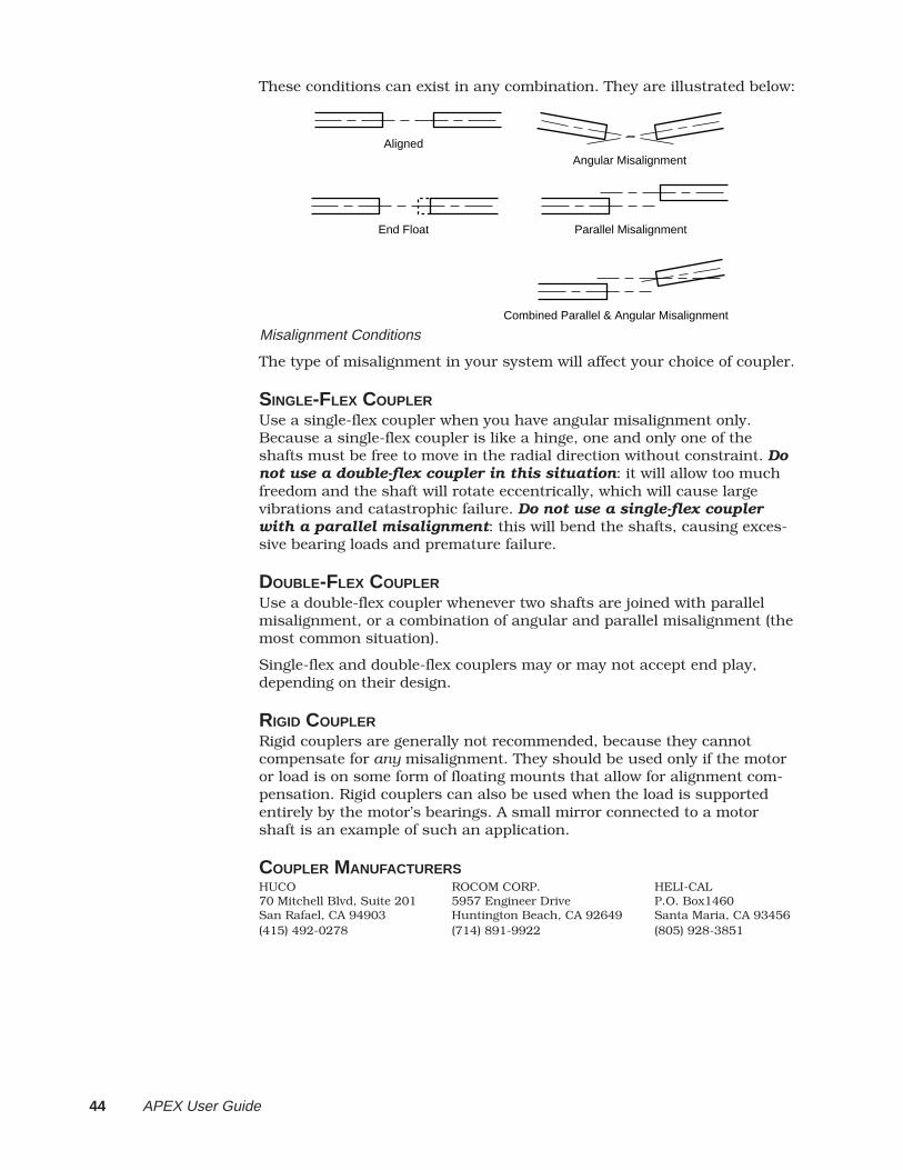
44 APEX User Guide
These conditions can exist in any combination. They are illustrated below:
Aligned
Parallel Misalignment
Combined Parallel & Angular Misalignment
End Float
Angular Misalignment
Misalignment Conditions
The type of misalignment in your system will affect your choice of coupler.
SINGLE-FLEX COUPLERUse a single-flex coupler when you have angular misalignment only.Because a single-flex coupler is like a hinge, one and only one of theshafts must be free to move in the radial direction without constraint. Donot use a double-flex coupler in this situation: it will allow too muchfreedom and the shaft will rotate eccentrically, which will cause largevibrations and catastrophic failure. Do not use a single-flex couplerwith a parallel misalignment: this will bend the shafts, causing exces-sive bearing loads and premature failure.
DOUBLE-FLEX COUPLERUse a double-flex coupler whenever two shafts are joined with parallelmisalignment, or a combination of angular and parallel misalignment (themost common situation).
Single-flex and double-flex couplers may or may not accept end play,depending on their design.
RIGID COUPLERRigid couplers are generally not recommended, because they cannotcompensate for any misalignment. They should be used only if the motoror load is on some form of floating mounts that allow for alignment com-pensation. Rigid couplers can also be used when the load is supportedentirely by the motor’s bearings. A small mirror connected to a motorshaft is an example of such an application.
COUPLER MANUFACTURERSHUCO ROCOM CORP. HELI-CAL70 Mitchell Blvd, Suite 201 5957 Engineer Drive P.O. Box1460San Rafael, CA 94903 Huntington Beach, CA 92649 Santa Maria, CA 93456(415) 492-0278 (714) 891-9922 (805) 928-3851
② Installation 45
RESONANCE ISSUES
A coupler that is too flexible may cause a motor to overshoot its com-manded position. When the encoder sends a position feedback signal, thecontroller will command a correction move in the opposite direction. If theresonant frequency of the system is too low (too flexible), the motor mayovershoot again and again. In extreme cases, the system could become anoscillator.
To solve resonance problems, increase the mechanical stiffness of thesystem to raise the resonant frequency so that it no longer causes aproblem.
If you use a servo as a direct replacement for a step motor, you may needto modify your mechanical coupling system to reduce resonance. Forexample, we recommend using a bellows-style coupler with servo motors,rather than the helical-style coupler that is often used with step motors.Helical couplers are often too flexible, with resonant frequencies that cancause problems. Bellows couplers are stiffer, and perform better in servosystems.
TUNING
Servo systems rely on feedback to control the motor motion. A servo loopconsists of the forward path through the motor, and the feedback path tothe drive. You can tune your system to optimize performance.
The APEX Drive can be configured as either a velocity or torque servo.When operated in torque mode, the APEX Drive amplifies a torque com-mand, but does not actually close a servo loop around the motor. Velocitymeasured by the resolver is used as a feedback signal. The APEX Drivedoes close an inner current loop, which ensures that actual currentmatches commanded current. When operated in velocity mode, the APEXDrive closes a servo loop around the motor and drive.
When using the APEX Drive with a PID servo controller, you shouldoperate the APEX Drive in torque mode. In this mode minimal tuning isrequired at the drive. When using the APEX Drive as a stand alone veloc-ity controller, or with a controller requiring additional damping, youshould operate the APEX Drive in velocity mode. Since brushed servomotors are traditionally operated in velocity mode, controllers in PLC andCNC type systems operate better when the drive is in velocity mode.
The APEX Drive is a reliable and simple component in a complete motioncontrol system. Unless you are operating it as a stand-alone velocitysystem, the real tuning of your system will take place in the controllerservo algorithm. The entire tuning process of the drive itself should takeonly a few minutes, and should be completed before tuning the controller.Your goal in tuning the APEX Drive is to make it perform responsively andpredictably.
46 APEX User Guide
TUNING WITH SM MOTORS
Maximum peak currents for APEX, SM, and NeoMetric Motors are threetimes higher than the motor's continuous current rating. If your system isnot tuned properly, and the motor oscillates or becomes unstable, exces-sive peak currents may cause the motor to overheat. The motor may bequickly damaged, before the thermostat can trigger the drive's Motor Faultcircuit.
To avoid motor damage, we recommend the following iterative tuningprocedure for a system.
➀ Adequately heatsink your motor, especially in temporary "bench top"procedures. Motors dissipate excess heat through their faceplate; thefaceplate must be mounted to a heatsink to ensure proper motor cooling.
➁ Set the drive's DIP switches for the lowest peak current.
➂ Apply tuning gains, and test your system's response. Adjust the gains untilyou achieve a satisfactory response. Before proceeding to the next step,ensure that the system is stable and that there are no mechanical problemsthat cause binding or jamming.
➃ Using the drive's DIP switches, increase peak current to the next higherlevel. Do not set the peak current higher than that specified for your par-ticular motor.
➄ Repeat steps 3 and 4 until you achieve performance satisfactory for yourapplication.
CAUTIONIf you use an SM Motor, set the drive's DIP switches at the lowest peak current level forinitial drive tuning. Motor damage due to excessive heating may result from high peak
currents and improper tuning values.
TORQUE MODE TUNING
In torque mode, the drive is a block of fixed gain (transconductance) set at5 mhos (amp/volt). The bandwidth of the drive is approximately 1 KHz.

② Installation 47
APEX TORQUE LOOP
LPF1kHz
Collective Gain Pot
Limiter
3 PhasePowerAmp
PHASE A
PHASE C
PHASE B
EARTH
Torque Command
-+
+-
Command+
Command-+
Offset Balance
+-X1
Velocity Error
Pro
gram
mab
le G
ain
RDC
CHA+CHA-CHB+ CHB- CHZ+CHZ- GND
+-
Vel IntegralGain Pot
Vel Int Enable
++
The items in grey have been defeated by dip switch and are not active in torque mode.
TORQUE MODE TUNING – PROCEDURE
In torque mode the only adjustment is to the Offset Balance potentiom-eter. This adjustment can remove, or zero, a DC voltage offset in thetorque amplifier. The procedure for adjusting the Offset Balance potenti-ometer was described earlier in this chapter.
SYMPTOMSYou will need to balance the Offset Balance potentiometer if your systemdisplays the following symptoms:
Offset Voltage: If the position controller is required to output a commandvoltage larger than 0.25V, the balance may need adjustment. This conditionis only detrimental if it limits the top end command. If the load is affectedby gravity or large amounts of friction, the controller may need to commanda higher voltage to overcome these forces and should not be balanced.
Motor Runs Away: If the motor runs away when enabled (without a positionloop closed) you should adjust the offset to zero.
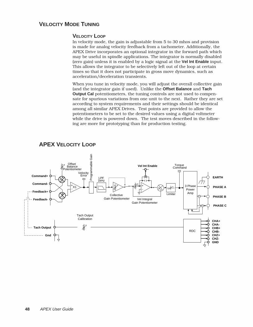
48 APEX User Guide
VELOCITY MODE TUNING
VELOCITY LOOPIn velocity mode, the gain is adjustable from 5 to 30 mhos and provisionis made for analog velocity feedback from a tachometer. Additionally, theAPEX Drive incorporates an optional integrator in the forward path whichmay be useful in spindle applications. The integrator is normally disabled(zero gain) unless it is enabled by a logic signal at the Vel Int Enable input.This allows the integrator to be selectively left out of the loop at certaintimes so that it does not participate in gross move dynamics, such asacceleration/deceleration transients.
When you tune in velocity mode, you will adjust the overall collective gain(and the integrator gain if used). Unlike the Offset Balance and TachOutput Cal potentiometers, the tuning controls are not used to compen-sate for spurious variations from one unit to the next. Rather they are setaccording to system requirements and their settings should be identicalamong all similar APEX Drives. Test points are provided to allow thepotentiometers to be set to the desired values using a digital voltmeterwhile the drive is powered down. The test moves described in the follow-ing are more for prototyping than for production testing.
APEX VELOCITY LOOP
LPF1kHz
Collective Gain Potentiometer
+-
Limiter
Vel IntegralGain Potentiometer
3 PhasePowerAmp
PHASE A
PHASE C
PHASE B
EARTH
Vel Int Enable Torque Command
-+
+-
Command+
Command-
Feedback+
Feedback-
+
Offset Balance
Potentiometer
+-X1
Velocity Error
Pro
gram
mab
le G
ain
Tach OutputCalibration
Tach Output
GndRDC
CHA+CHA-CHB+ CHB- CHZ+CHZ- GND
++
② Installation 49
ADJUSTMENTSIn velocity mode the Offset Balance , Collective Gain , and Vel Integral Gainpotentiometers are the active adjustments.
Adjustment Type Description
Offset Balance 15 (±3) turn pot Positive and negativeadjustment of the DCvalue of the velocitycommand signal.
Collective Gain 15(±3) turn pot Overall amplification ofthe velocity error. Thisadjustment should beused as velocity gainwhen operating with aposition c ontroller.The gain will be highwith large inertia andwill add damping to aposition servo system.This gain is defeatableby dip switch.
Velocit Integral Gain 15(±3) turn pot Corrects for steady stateerrors in velocity.Should only be used instand alone velocityapplications. This gainis defeatable by dipswitch.
SYMPTOMSYou will need to adjust the velocity gains if your system displays any ofthe following symptoms:
Offset Voltage: If the position controller is required to output a commandvoltage larger than 0.25V when the motor is under no load, the balance mayneed adjustment. This condition is only detrimental if it limits the top endcommand. If the load is affected by gravity or large amounts of friction, thecontroller may need to command a higher voltage to overcome these forcesand should not be balanced.
Motor Runs Away: If the motor runs away when enabled (without a positionloop closed) the offset can be adjusted to zero so the motor will not run awaywhen enabled.
Sluggish System: If the motor lacks stiffness, the collective gain is too low.When the load inertia increases, the collective gain must be increasedproportionally.
Ringing: If the system rings excessively when changing position and velocity,your system is either underdamped or aggravating a mechanical resonancein the system. By increasing the Collective gain you will increase theresponsiveness of the velocity loop and increase damping.
Steady State Errors: This will occur when operating the APEX Drive in avelocity mode only (no position controller). If the motor will not reach thecommanded velocity, an external force such as friction is restraining themotor. By increasing the Velocity Integral Gain, the APEX Drive will in-crease the command voltage to overcome steady state velocity errors.
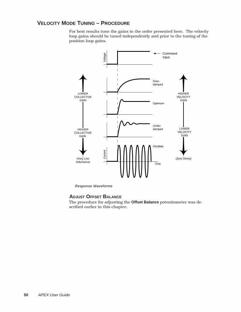
50 APEX User Guide
VELOCITY MODE TUNING – PROCEDURE
For best results tune the gains in the order presented here. The velocityloop gains should be tuned independently and prior to the tuning of theposition loop gains.
Time
Response Waveforms
Vol
tage
Over-damped
Optimum
Under-damped
Command Input
Oscillate
Cur
rent
HIGHERVELOCITY
GAIN
LOWERVELOCITY
GAIN
(Zero Ohms)
LOWER COLLECTIVE
GAIN
HIGHER COLLECTIVE
GAIN
(Very LowInductance)
ADJUST OFFSET BALANCEThe procedure for adjusting the Offset Balance potentiometer was de-scribed earlier in this chapter.
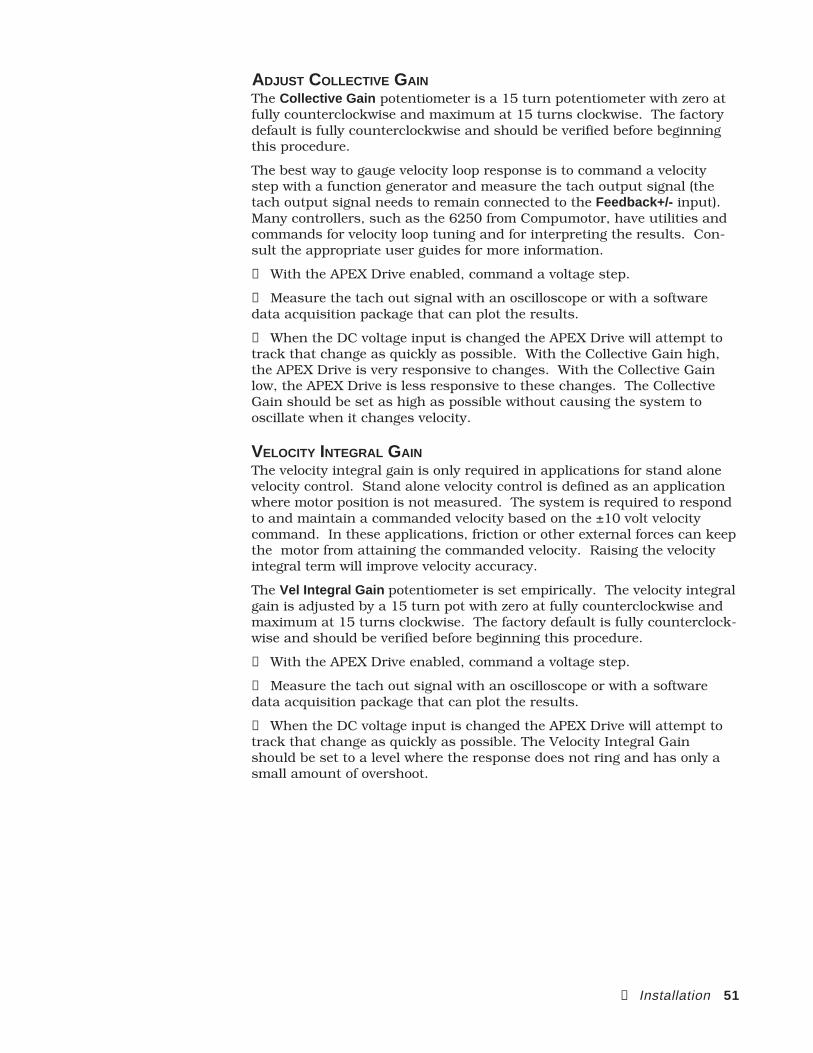
② Installation 51
ADJUST COLLECTIVE GAINThe Collective Gain potentiometer is a 15 turn potentiometer with zero atfully counterclockwise and maximum at 15 turns clockwise. The factorydefault is fully counterclockwise and should be verified before beginningthis procedure.
The best way to gauge velocity loop response is to command a velocitystep with a function generator and measure the tach output signal (thetach output signal needs to remain connected to the Feedback+/- input).Many controllers, such as the 6250 from Compumotor, have utilities andcommands for velocity loop tuning and for interpreting the results. Con-sult the appropriate user guides for more information.
➀ With the APEX Drive enabled, command a voltage step.
➁ Measure the tach out signal with an oscilloscope or with a softwaredata acquisition package that can plot the results.
➂ When the DC voltage input is changed the APEX Drive will attempt totrack that change as quickly as possible. With the Collective Gain high,the APEX Drive is very responsive to changes. With the Collective Gainlow, the APEX Drive is less responsive to these changes. The CollectiveGain should be set as high as possible without causing the system tooscillate when it changes velocity.
VELOCITY INTEGRAL GAINThe velocity integral gain is only required in applications for stand alonevelocity control. Stand alone velocity control is defined as an applicationwhere motor position is not measured. The system is required to respondto and maintain a commanded velocity based on the ±10 volt velocitycommand. In these applications, friction or other external forces can keepthe motor from attaining the commanded velocity. Raising the velocityintegral term will improve velocity accuracy.
The Vel Integral Gain potentiometer is set empirically. The velocity integralgain is adjusted by a 15 turn pot with zero at fully counterclockwise andmaximum at 15 turns clockwise. The factory default is fully counterclock-wise and should be verified before beginning this procedure.
➀ With the APEX Drive enabled, command a voltage step.
➁ Measure the tach out signal with an oscilloscope or with a softwaredata acquisition package that can plot the results.
➂ When the DC voltage input is changed the APEX Drive will attempt totrack that change as quickly as possible. The Velocity Integral Gainshould be set to a level where the response does not ring and has only asmall amount of overshoot.
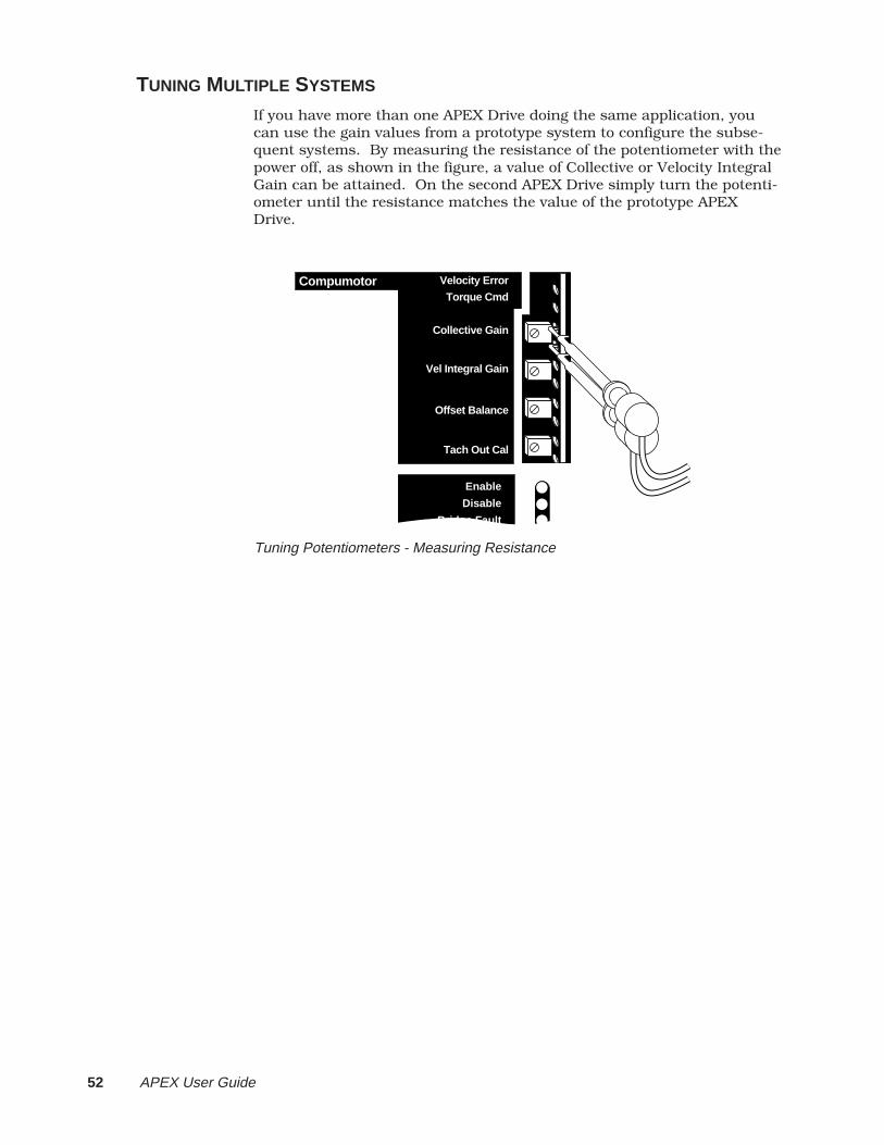
52 APEX User Guide
TUNING MULTIPLE SYSTEMS
If you have more than one APEX Drive doing the same application, youcan use the gain values from a prototype system to configure the subse-quent systems. By measuring the resistance of the potentiometer with thepower off, as shown in the figure, a value of Collective or Velocity IntegralGain can be attained. On the second APEX Drive simply turn the potenti-ometer until the resistance matches the value of the prototype APEXDrive.
Enable
Disable
Bridge Fault
Compumotor Velocity Error
Torque Cmd
Collective Gain
Vel Integral Gain
Offset Balance
Tach Out Cal
Tuning Potentiometers - Measuring Resistance

➂ Special Features 53
3SpecialFeatures
IN THIS CHAPTER
Motor Braking
Regeneration Solutions
Sharing the Power Bus: V Bus+ and V Bus-
Current Foldback (I2T Limit)
Front Panel Test Points
Resolver Alignment
C H A P T E R THREE

54 APEX User Guide
MOTOR BRAKING (FAULT RELAY±)
If the APEX Drive faults, for any reason, the drive will be disabled and themotor will freewheel. If a freewheeling load is unacceptable, use the faultrelay terminals, Fault Relay+ and Fault Relay– , to control a motor brake.
The fault relay inside the APEX Drive is normally open. This means thatwhen the drive is faulted or disabled, or when the power is off, the relaywill be open. When the APEX Drive is enabled, it energizes the relay coil,and holds the relay closed. The relay is rated for 5 amps at 24VDC or120VAC.
Most motor brakes have a coil that, when energized, will release thebrake. To control a brake with the fault relay terminals:
➀ Connect the power source for the brake to one of the fault relay terminals.
➁ Connect the other fault relay terminal to the brake.
➂ If you use a DC power source, you may need to connect a diode across thebrake coil to reduce voltage spikes when the brake is engaged or disen-gaged. A 1N4936 diode, or equivalent, should be sufficient.
EXAMPLE 1: APEX and NeoMetric motors are available from Compumotorwith an optional mechanical brake. Call Compumotor’s Customer ServiceDepartment (800-722-2282) for more information. The next drawingshows how to connect the brake to the fault relay terminals.
APEX Drive
Fault Relay+
Fault Relay–
+5VDC to +24VDC
Pull-upResistor
Fault Out
Fault All
Resolver Cable
Flying Leads from Resolver Connector
+5VDC+24VDC
OptionalDiode(1N4936)
Drive Condition Power OFF Disabled Faulted Enabled
Relay State Open Open Open Closed
Fault Relay Max Current Rating 5A at 24VDC, or 5A at 120VAC
Relay Type: Normally Open
Fault Relay with Mechanical Brake
24VDC is applied, through the fault relay terminals, to one of the flyingleads on the motor’s resolver connector. The other lead is connected toground. An optional diode is shown installed between the two leads. Thediode’s polarity is correct as shown.
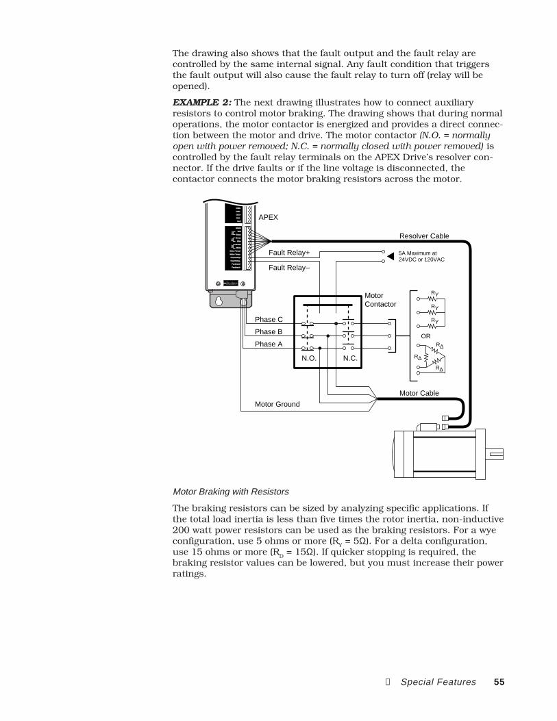
➂ Special Features 55
The drawing also shows that the fault output and the fault relay arecontrolled by the same internal signal. Any fault condition that triggersthe fault output will also cause the fault relay to turn off (relay will beopened).
EXAMPLE 2: The next drawing illustrates how to connect auxiliaryresistors to control motor braking. The drawing shows that during normaloperations, the motor contactor is energized and provides a direct connec-tion between the motor and drive. The motor contactor (N.O. = normallyopen with power removed; N.C. = normally closed with power removed) iscontrolled by the fault relay terminals on the APEX Drive’s resolver con-nector. If the drive faults or if the line voltage is disconnected, thecontactor connects the motor braking resistors across the motor.
Resolver Cable
APEX
Fault Relay+
MotorContactor
Phase C
Phase B
Phase A
Motor Ground
N.O. N.C.
RY
ORR∆
R∆
R∆
RY
RY
Motor Cable
Fault Relay–
5A Maximum at 24VDC or 120VAC
CHA+
CHA -
CHB+
CHB -
CHZ+
CHZ -
Gnd
Shield
Red
Black
Green
Blue
Brown
White
Motor Temp+
Motor Temp -
Fault Relay+
Fault Relay -
Feedback+
Feedback -
Ref
Sin
Cos
Motor Braking with Resistors
The braking resistors can be sized by analyzing specific applications. Ifthe total load inertia is less than five times the rotor inertia, non-inductive200 watt power resistors can be used as the braking resistors. For a wyeconfiguration, use 5 ohms or more (RY = 5Ω). For a delta configuration,use 15 ohms or more (RD = 15Ω). If quicker stopping is required, thebraking resistor values can be lowered, but you must increase their powerratings.
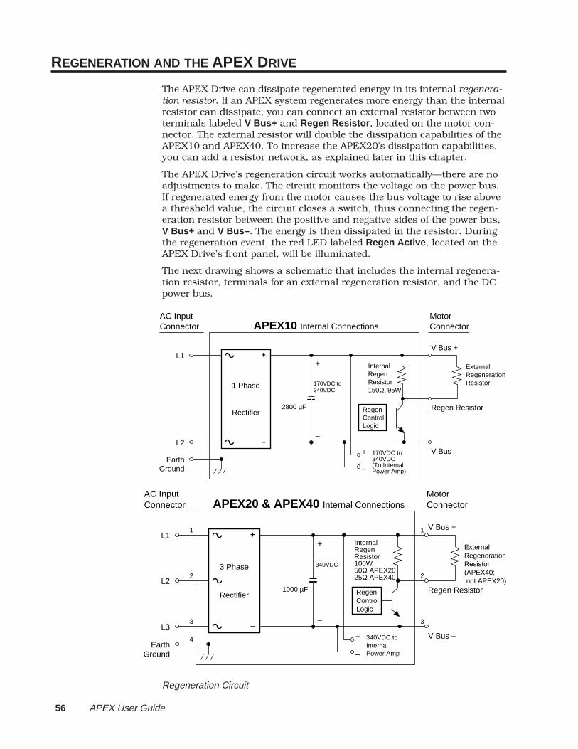
56 APEX User Guide
REGENERATION AND THE APEX DRIVE
The APEX Drive can dissipate regenerated energy in its internal regenera-tion resistor. If an APEX system regenerates more energy than the internalresistor can dissipate, you can connect an external resistor between twoterminals labeled V Bus+ and Regen Resistor , located on the motor con-nector. The external resistor will double the dissipation capabilities of theAPEX10 and APEX40. To increase the APEX20's dissipation capabilities,you can add a resistor network, as explained later in this chapter.
The APEX Drive’s regeneration circuit works automatically—there are noadjustments to make. The circuit monitors the voltage on the power bus.If regenerated energy from the motor causes the bus voltage to rise abovea threshold value, the circuit closes a switch, thus connecting the regen-eration resistor between the positive and negative sides of the power bus,V Bus+ and V Bus– . The energy is then dissipated in the resistor. Duringthe regeneration event, the red LED labeled Regen Active , located on theAPEX Drive’s front panel, will be illuminated.
The next drawing shows a schematic that includes the internal regenera-tion resistor, terminals for an external regeneration resistor, and the DCpower bus.
APEX10 Internal ConnectionsMotorConnector
AC InputConnector
1 Phase
Rectifier
170VDC to340VDC
+
–
+
–
Regen Control Logic
ExternalRegenerationResistor
V Bus –
L1
L2
EarthGround
2800 µF
InternalRegenResistor150Ω, 95W
V Bus +
170VDC to340VDC(To InternalPower Amp)–
+
Regen Resistor
APEX20 & APEX40 Internal ConnectionsMotorConnector
1
AC InputConnector
3 Phase
Rectifier
340VDC
+
–
+
–
Regen Control Logic
2
ExternalRegenerationResistor(APEX40; not APEX20)
3
V Bus –
1L1
2L2
3L3
4Earth
Ground
1000 µF
InternalRegenResistor100W50Ω APEX2025Ω APEX40
V Bus +
340VDC toInternalPower Amp–
+
Regen Resistor
Regeneration Circuit

➂ Special Features 57
FAULTS CAUSED BY EXCESSIVE REGENERATION
The APEX Drive’s protection circuitry monitors regeneration activity, andcan trigger one of two fault conditions if excess regeneration occurs. Thedrive's internal IGBT power switch is the component that determines thelimits. Exceeding the regeneration resistor’s continuous power rating willcause a Regen Fault . Exceeding the resistor’s peak power rating will causean Overvoltage Fault . Either of these faults will shut down the drive, to
safeguard the system.
Details regarding the regeneration fault and overvoltage fault are ex-plained below.
REGENERATION FAULTA regeneration fault indicates that the continuous power dissipationcapabilities of the regeneration resistor have been exceeded.
The resistor's temperature is determined by the average power dissipationover time and is affected by such things as the length of time the resistoris on, how much power it dissipates, and the length of time it is off. Whenregeneration occurs, the temperature will increase during decelerationand during a repetitive move profile. The temperature will decrease afterregeneration stops—when the motor is accelerating, moving at constantvelocity, or at rest.
If the average power dissipated in the resistor is less than the continuousrating in the table above, the temperature will stay below damaging levels.If the average power dissipated is greater than the continuous rating, thetemperature may rise to a level that can permanently damage the resistor;however, the regeneration fault circuit will shut down the drive beforetemperatures reach this level. The purpose of the regeneration fault is toprotect the regeneration resistor from damage due to high temperatures.
Nominal Operating Voltage:(based on AC input)
170VDC-340VDC360VDC340VDC
Regen Resistor Turns ON:
390VDC390VDC390VDC
OvervoltageFaultTurns ON:
420VDC420VDC420VDC
APEX10APEX20APEX40
Dissipation ratings for the internal regeneration resistor are:
APEX10APEX20APEX40
Continuous Power Dissipaton Rating
95 watts100 watts100 watts
Peak Power Dissipation Rating
1KW3KW6KW
Important specifications for the regeneration circuit are:
58 APEX User Guide
You can clear the regeneration fault by cycling power or sending a resetsignal to the APEX Drive’s reset input. To cycle power, turn off AC powerto Control L1/Control L2 , then turn the power back on. However, if theresistor has not had adequate time to cool, and the conditions leading tothe regeneration fault persist, you may damage the regenerationresistor by cycling power repeatedly. Information about continuouspower dissipation in the regeneration resistor is lost when power is cycled.
CAUTIONRepeatedly cycling power or resetting the drive to clear regeneration faults may damage
the regeneration resistor.
OVERVOLTAGE FAULTAn overvoltage fault indicates that the peak power dissipation capabilitiesof the regeneration resistor have been exceeded.
Regeneration causes the voltage on the DC power bus to rise. The regen-eration resistor will turn on when the bus voltage reaches 390VDC. Peakpower dissipation occurs at the moment the resistor turns on. The peakpower value is determined by the size of the resistor, in ohms, and thevoltage across it:
APEX10 Peak Power = V 2
R= 390VDC( )2
150Ω≈ 1000W (1KW )
APEX20 Peak Power = V 2
R= 390VDC( )2
50Ω≈ 3000W (3 KW )
APEX40 Peak Power = V 2
R= 390VDC( )2
25Ω≈ 6000W (6 KW )
As soon as the resistor turns on, regenerated power begins to be dissi-pated in the resistor, and, in most applications, bus voltage drops. Whenthe voltage falls below 375VDC, the resistor turns off. If the motor is stillproducing regenerated power, the bus voltage will rise again, the resistorwill turn on at 390VDC, and the cycle will repeat over and over until themotor no longer produces enough power to turn on the regenerationresistor.
However, some applications can regenerate more than the peak powershown in the above three equations. Too much peak power can overwhelmthe regeneration circuit—the bus voltage will continue to rise, even whilethe resistor is on. To protect the system from excessive voltages, anovervoltage circuit monitors the bus voltage, and triggers the overvoltagefault if the voltage exceeds 420VDC.
An overvoltage fault will shut down the drive. The red LED labeledOver Voltage , located on the APEX Drive’s front panel, will be illuminated.You can clear the fault by sending a reset signal to the APEX Drive’s resetinput, or by cycling power.

➂ Special Features 59
WHEN DO YOU NEED AN EXTERNAL REGENERATION RESISTOR?The APEX Drive’s regeneration control circuit was designed to automati-cally deal with regenerated power from almost all applications. Occasion-ally, however, an application situation arises in which regeneration willcause more power dissipation than the internal resistor can safely toler-ate. If you have an APEX10 or APEX40 Drive, you can connect an externalregeneration resistor to double the power that the system can dissipate.
If you have an APEX20 Drive, you cannot simply add an external resistor.The drive's internal power switch is already at its maximum rated current;adding an external resistor would increase the current, and damage thedrive. You can, however, build your own external resistor network in placeof the internal circuit. Use the procedures in this section to determineyour system's needs. Then, if you need more continuous dissipationcapability, see Building Your Own Regeneration Circuit in the next section.
To determine whether or not you need an external resistor, you can useone of two methods:
Empirical Method
Calculation Method
EMPIRICAL METHODThe empirical method uses a trial procedure to determine whether excessregeneration will cause a regeneration or overvoltage fault. Operate yoursystem (or a prototype of your system) and observe the results of regen-eration. When your system decelerates, the Regen Active LED will beilluminated whenever regeneration turns the internal resistor on.
If the system’s regeneration levels are too high, eventually either a regen-eration fault or an overvoltage fault will shut down the APEX Drive. (Besure to let your system run for a long enough time to see if the regenera-tion fault will be triggered.) At this point, you have two options:
Modify the system’s move profile
Install an external regeneration resistor
By changing the move profile—less torque, slower velocities, or a longertime between moves, for example—you may be able to reduce the regen-eration to a lower level, so that the fault no longer occurs.
By installing an external resistor, you can double the regenerationcircuit’s power dissipation capabilities. With the resistor installed, thecircuit’s specifications become:
After you alter the move profile, or install the external resistor, run thesystem again to verify that regeneration no longer causes a fault.
APEX10
APEX20
APEX40
Continuous Power Dissipation Rating
100 watts
N/A
180 watts
Peak PowerDissipation Rating
2 KW
N/A
12KW
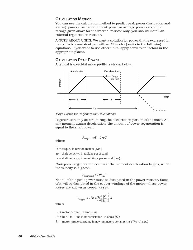
60 APEX User Guide
CALCULATION METHODYou can use the calculation method to predict peak power dissipation andaverage power dissipation. If peak power or average power exceed theratings given above for the internal resistor only, you should install anexternal regeneration resistor.
A NOTE ABOUT UNITS: We want a solution for power that is expressed inwatts. To be consistent, we will use SI (metric) units in the followingequations. If you want to use other units, apply conversion factors in theappropriate places.
CALCULATING PEAK POWERA typical trapezoidal move profile is shown below.
Time
Vel
ocity
t1
Acceleration
t2
t1
Deceleration
Vmax(in rps)
Move Profile for Regeneration Calculations
Regeneration only occurs during the deceleration portion of the move. Atany moment during deceleration, the amount of power regeneration isequal to the shaft power:
Pshaft = ωT = 2πvTwhere
T = torque, in newton meters (Nm)
ω = shaft velocity, in radians per second
v = shaft velocity, in revolutions per second (rps)
Peak power regeneration occurs at the moment deceleration begins, whenthe velocity is highest.
Pshaft ( peak ) = 2πvmaxT
Not all of this peak power must be dissipated in the power resistor. Someof it will be dissipated in the copper windings of the motor—these powerlosses are known as copper losses.
Pcopper = I2 R = 32
T
kT
2
R
where
I = motor current, in amps (A)
R = line – to – line motor resistance, in ohms (Ω)
kt = motor torque constant, in newton meters per amp rms (Nm / A rms)
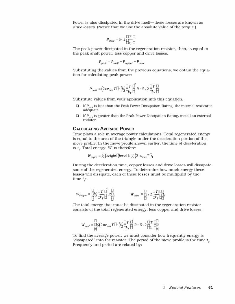
➂ Special Features 61
Power is also dissipated in the drive itself—these losses are known asdrive losses. (Notice that we use the absolute value of the torque.)
Pdrive = 5 2T
kT
The peak power dissipated in the regeneration resistor, then, is equal tothe peak shaft power, less copper and drive losses.
Ppeak = Pshaft − Pcopper − Pdrive
Substituting the values from the previous equations, we obtain the equa-tion for calculating peak power:
Ppeak = 2πvmaxT( ) − 32
T
kT
2
R − 5 2T
kT
Substitute values from your application into this equation.
If Ppeak is less than the Peak Power Dissipation Rating, the internal resistor is
adequate
If Ppeak is greater than the Peak Power Dissipation Rating, install an external
resistor
CALCULATING AVERAGE POWERTime plays a role in average power calculations. Total regenerated energyis equal to the area of the triangle under the deceleration portion of themove profile. In the move profile shown earlier, the time of decelerationis t
1. Total energy, W, is therefore:
Wregen = 12 height( ) base( ) = 1
2 2πvmaxT( )t1During the deceleration time, copper losses and drive losses will dissipatesome of the regenerated energy. To determine how much energy theselosses will dissipate, each of these losses must be multiplied by thetime t
1:
Wcopper = 32
T
kT
2
R
t1 Wdrive = 5 2
T
kT
t1
The total energy that must be dissipated in the regeneration resistorconsists of the total regenerated energy, less copper and drive losses:
Wtotal = 12 2πvmaxT( ) − 3
2T
kT
2
R − 5 2T
kT
t1
To find the average power, we must consider how frequently energy is“dissipated” into the resistor. The period of the move profile is the time t
2.
Frequency and period are related by:

62 APEX User Guide
frequency = f = 1t2
To find the average power dissipation in the resistor, we can multiply theequation for total energy by the frequency, or, as shown below, we candivide by the period of the repetitive move profile.
Finally, we obtain the equation for average power:
Paverage = 12 2πvmaxT( ) − 3
2T
kT
2
R − 5 2T
kT
t1t2
Substitute values from your application into this equation.
If Paverage is less than the Continuous Power Dissipation Rating, the internal
resistor is adequate
If Paverage is greater than the Continuous Power Dissipation Rating, install an
external resistor
INSTALLING AN EXTERNAL REGENERATION RESISTORIf you install an external resistor, ensure that it is properly mounted andadequately cooled. The internal resistor is cooled by the APEX Drive’s fan.The external resistor should be maintained at the same temperature, orcooler, as the internal resistor. Excessive heating of the external resistorcan cause component failure.
CAUTIONAdequately cool the external resistor. Forced air cooling may be required. Maintain resistor
temperature at same or lower temperature as internal resistor.
Specifications for the internal resistor are as follows:
APEX10:
150 ohm, 95 watt, 5% non-inductive resistor
Manufacturer Name: Dale
Manufacturer Part Number: NHL-95-16N 150 OHM5%, 3/16 QUICK CONNECT
You can order this resistor fromCompumotor. The part name is: APEX10 REGEN KIT
APEX20: (for reference only; do not install external resistor)
50 ohm, 100 watt, 5% non-inductive resistor
Manufacturer Name: Memcor-Truohm Inc.
Manufacturer Part Number: FRV01006-2500-QM-NI("NI" - Non Inductive)
Mounting Bracket: Memcor-Truohm Inc.Part Number 1141-006-001
APEX40:
25 ohm, 100 watt, 5% non-inductive resistor
Manufacturer Name: Memcor-Truohm Inc.
Manufacturer Part Number: FRV01006-2250-QM-NI("NI" - Non Inductive)

➂ Special Features 63
Mounting Bracket: Memcor-Truohm Inc.Part Number 1141-006-001
You can order this resistor fromCompumotor. The part name is: APEX40 REGEN KIT
Use these, or equivalently rated resistors, for your external resistor. Besure to specify a non-inductive resistor.
To connect the external resistor, wire its two terminals to V Bus+ andRegen Resistor, located on the motor connector. Do not install more thanone external resistor. The regeneration control circuit will automaticallydissipate half of the excess regenerated power in the external resistor(provided that the external resistor has the same resistance (ohms) as theinternal resistor.)
CAUTIONDo not install more than one external regeneration resistor with the APEX10 or APEX40.
Do not install an external regeneration resistor with the APEX20.
BUILDING YOUR OWN REGENERATION CIRCUITIf you need more continuous power dissipation than the resistors provide(internal and external for the APEX10 and APEX40; internal only for theAPEX 20), you can design and build your own network of external regen-eration resistors.
The next table shows specifications for maximum continuous and peakdissipation that the drive can sustain. It also shows the minimum resis-tance for an external network. Do not use a resistor network with lessresistance than the values in this table.
Continuous Peak Resistance (min)
APEX10 286 watts 2080 watts 75 ohms
APEX20 1560 watts 3112 watts 50 ohms
APEX40 5760 watts 12480 watts 12.5 ohms
The drive's internal IGBT power switch is the component that determinesthe specifications above. With the standard external resistors discussedearlier, the switch is already at its peak power dissipation level. However,the switch can dissipate more continuous power than the standardresistors allow. Your network, therefore, can dissipate additional continu-ous power—but must not dissipate more peak power. This is shown in thetable above.
To use an external network, you must take the following two steps.
1. Set DIP Switch 1, position #1, in the ON position. This disables the drive'sRegen Fault circuit.
2. Disconnect the internal regeneration resistor.
Step 2 above requires opening the drive's cover. Please callCompumotor's Applications Engineering department (see the insidefront cover of this manual for the toll free number) for instructionson opening the cover and disconnecting the resistor, and to obtainadditional information about designing your external resistor net-work.
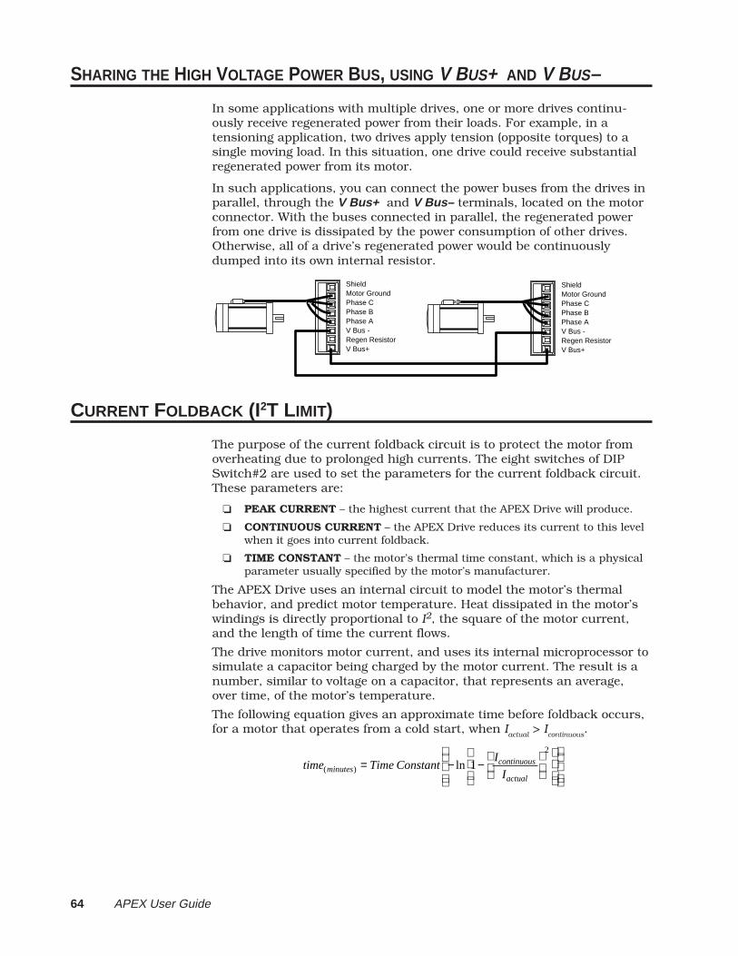
64 APEX User Guide
SHARING THE HIGH VOLTAGE POWER BUS, USING V BUS+ AND V BUS–
In some applications with multiple drives, one or more drives continu-ously receive regenerated power from their loads. For example, in atensioning application, two drives apply tension (opposite torques) to asingle moving load. In this situation, one drive could receive substantialregenerated power from its motor.
In such applications, you can connect the power buses from the drives inparallel, through the V Bus+ and V Bus– terminals, located on the motorconnector. With the buses connected in parallel, the regenerated powerfrom one drive is dissipated by the power consumption of other drives.Otherwise, all of a drive’s regenerated power would be continuouslydumped into its own internal resistor.
ShieldMotor GroundPhase CPhase BPhase AV Bus -Regen ResistorV Bus+
ShieldMotor GroundPhase CPhase BPhase AV Bus -Regen ResistorV Bus+
CURRENT FOLDBACK (I2T LIMIT)
The purpose of the current foldback circuit is to protect the motor fromoverheating due to prolonged high currents. The eight switches of DIPSwitch#2 are used to set the parameters for the current foldback circuit.These parameters are:
PEAK CURRENT – the highest current that the APEX Drive will produce.
CONTINUOUS CURRENT – the APEX Drive reduces its current to this levelwhen it goes into current foldback.
TIME CONSTANT – the motor’s thermal time constant, which is a physicalparameter usually specified by the motor’s manufacturer.
The APEX Drive uses an internal circuit to model the motor’s thermalbehavior, and predict motor temperature. Heat dissipated in the motor’swindings is directly proportional to I2, the square of the motor current,and the length of time the current flows.
The drive monitors motor current, and uses its internal microprocessor tosimulate a capacitor being charged by the motor current. The result is anumber, similar to voltage on a capacitor, that represents an average,over time, of the motor’s temperature.
The following equation gives an approximate time before foldback occurs,for a motor that operates from a cold start, when I
actual > I
continuous.
time(minutes) = Time Constant − ln 1− Icontinuous
Iactual
2
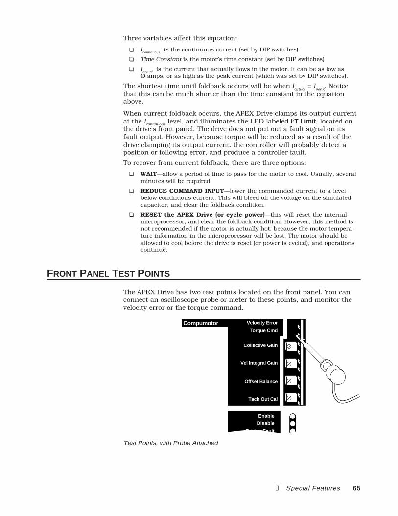
➂ Special Features 65
Three variables affect this equation:
Icontinuous
is the continuous current (set by DIP switches)
Time Constant is the motor’s time constant (set by DIP switches)
Iactual
is the current that actually flows in the motor. It can be as low asØ amps, or as high as the peak current (which was set by DIP switches).
The shortest time until foldback occurs will be when Iactual
= Ipeak
. Noticethat this can be much shorter than the time constant in the equationabove.
When current foldback occurs, the APEX Drive clamps its output currentat the I
continuous level, and illuminates the LED labeled I2T Limit , located on
the drive’s front panel. The drive does not put out a fault signal on itsfault output. However, because torque will be reduced as a result of thedrive clamping its output current, the controller will probably detect aposition or following error, and produce a controller fault.
To recover from current foldback, there are three options:
WAIT—allow a period of time to pass for the motor to cool. Usually, severalminutes will be required.
REDUCE COMMAND INPUT—lower the commanded current to a levelbelow continuous current. This will bleed off the voltage on the simulatedcapacitor, and clear the foldback condition.
RESET the APEX Drive (or cycle power)—this will reset the internalmicroprocessor, and clear the foldback condition. However, this method isnot recommended if the motor is actually hot, because the motor tempera-ture information in the microprocessor will be lost. The motor should beallowed to cool before the drive is reset (or power is cycled), and operationscontinue.
FRONT PANEL TEST POINTS
The APEX Drive has two test points located on the front panel. You canconnect an oscilloscope probe or meter to these points, and monitor thevelocity error or the torque command.
Enable
Disable
Bridge Fault
Velocity ErrorTorque Cmd
Compumotor Velocity Error
Torque Cmd
Collective Gain
Vel Integral Gain
Offset Balance
Tach Out Cal
Test Points, with Probe Attached
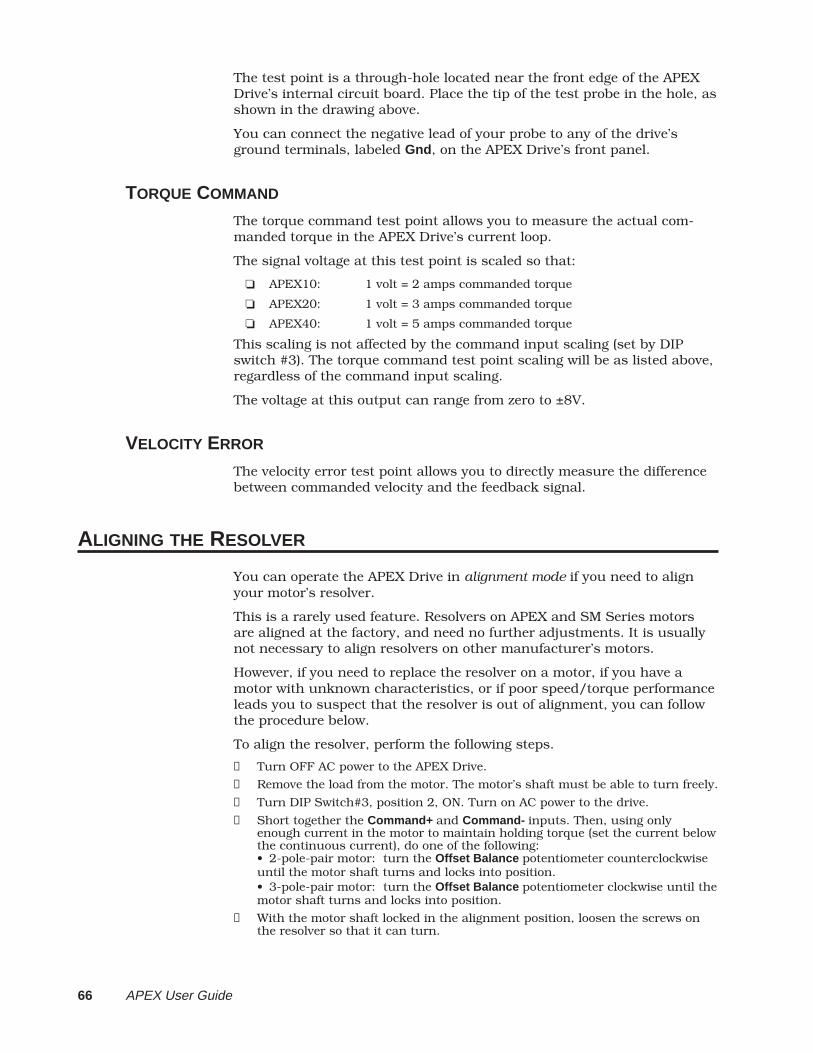
66 APEX User Guide
The test point is a through-hole located near the front edge of the APEXDrive’s internal circuit board. Place the tip of the test probe in the hole, asshown in the drawing above.
You can connect the negative lead of your probe to any of the drive’sground terminals, labeled Gnd , on the APEX Drive’s front panel.
TORQUE COMMAND
The torque command test point allows you to measure the actual com-manded torque in the APEX Drive’s current loop.
The signal voltage at this test point is scaled so that:
APEX10: 1 volt = 2 amps commanded torque
APEX20: 1 volt = 3 amps commanded torque
APEX40: 1 volt = 5 amps commanded torque
This scaling is not affected by the command input scaling (set by DIPswitch #3). The torque command test point scaling will be as listed above,regardless of the command input scaling.
The voltage at this output can range from zero to ±8V.
VELOCITY ERROR
The velocity error test point allows you to directly measure the differencebetween commanded velocity and the feedback signal.
ALIGNING THE RESOLVER
You can operate the APEX Drive in alignment mode if you need to alignyour motor’s resolver.
This is a rarely used feature. Resolvers on APEX and SM Series motorsare aligned at the factory, and need no further adjustments. It is usuallynot necessary to align resolvers on other manufacturer’s motors.
However, if you need to replace the resolver on a motor, if you have amotor with unknown characteristics, or if poor speed/torque performanceleads you to suspect that the resolver is out of alignment, you can followthe procedure below.
To align the resolver, perform the following steps.
➀ Turn OFF AC power to the APEX Drive.
➁ Remove the load from the motor. The motor’s shaft must be able to turn freely.
➂ Turn DIP Switch#3, position 2, ON. Turn on AC power to the drive.
➃ Short together the Command+ and Command- inputs. Then, using onlyenough current in the motor to maintain holding torque (set the current belowthe continuous current), do one of the following:• 2-pole-pair motor: turn the Offset Balance potentiometer counterclockwiseuntil the motor shaft turns and locks into position.• 3-pole-pair motor: turn the Offset Balance potentiometer clockwise until themotor shaft turns and locks into position.
➄ With the motor shaft locked in the alignment position, loosen the screws onthe resolver so that it can turn.

➂ Special Features 67
➅ Slowly rotate the resolver while you observe the APEX Drive’s front panelLEDs. When the resolver is in the correct position, both the Motor Fault andthe I2T Limit LEDs will be illuminated. When the resolver is close to thecorrect position, only one of the LEDs will be illuminated. When the rotor isnot close to the correct position, no LED will be illuminated.
➆ With the resolver in the correct position (both LEDs illuminated), tighten thescrews on the resolver so that its case can no longer rotate.
➇ You may need to adjust the offset balance potentiometer, to stop the motorfrom turning. See instructions in Chapter ➁ Installation for adjusting the offsetbalance potentiometer for more information.
➈ Turn off AC power, and turn DIP Switch#3, position 2, OFF.
➉ Resolver alignment is now complete. You can resume normal operations.
While the drive is in alignment mode, it commutates current as follows:
For 2–pole motors: Current out of Phase B and into Phase C
For 3–pole motors: Two equal currents out of Phase B and C. Bothcurrents into Phase A.
COMMUTATION TEST MODE
You can operate the APEX Drive in commutation test mode to troubleshootproblems. The drive ignores resolver or Hall effect input, and commutatesthe motor at one revolution per second. Motor current is proportional tocommand input voltage.
See Chapter 5 Troubleshooting for a full description of commutation testmode operations.

68 APEX User Guide
This page left blank intentionally.

➃ Hardware Reference 69
4HardwareReference
IN THIS CHAPTER
APEX Drive Specifications
Input/Output Pinouts and Circuit Diagrams
Motor Specifications, Speed/Torque curves, and Dimensions
C H A P T E R FOUR
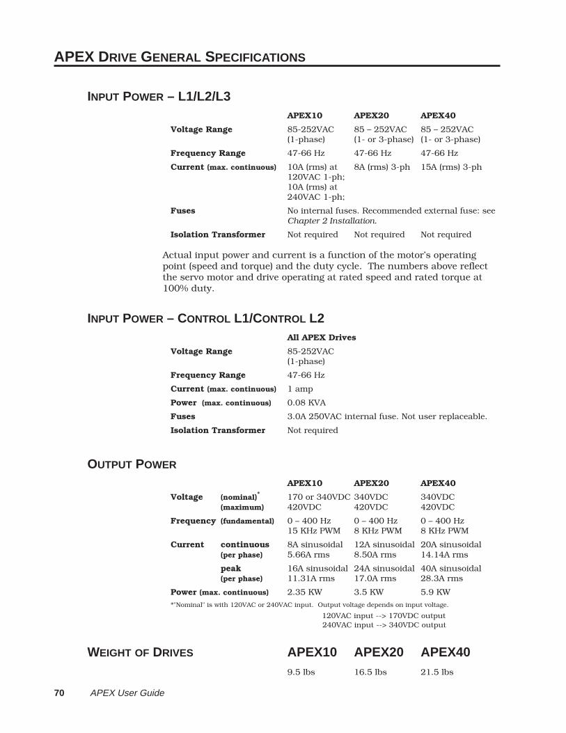
70 APEX User Guide
APEX DRIVE GENERAL SPECIFICATIONS
INPUT POWER – L1/L2/L3APEX10 APEX20 APEX40
Voltage Range 85-252VAC 85 – 252VAC 85 – 252VAC(1-phase) (1- or 3-phase) (1- or 3-phase)
Frequency Range 47-66 Hz 47-66 Hz 47-66 Hz
Current (max. continuous) 10A (rms) at 8A (rms) 3-ph 15A (rms) 3-ph120VAC 1-ph;10A (rms) at240VAC 1-ph;
Fuses No internal fuses. Recommended external fuse: seeChapter 2 Installation.
Isolation Transformer Not required Not required Not required
Actual input power and current is a function of the motor’s operatingpoint (speed and torque) and the duty cycle. The numbers above reflectthe servo motor and drive operating at rated speed and rated torque at100% duty.
INPUT POWER – CONTROL L1/CONTROL L2All APEX Drives
Voltage Range 85-252VAC(1-phase)
Frequency Range 47-66 Hz
Current (max. continuous) 1 amp
Power (max. continuous) 0.08 KVA
Fuses 3.0A 250VAC internal fuse. Not user replaceable.
Isolation Transformer Not required
OUTPUT POWER
APEX10 APEX20 APEX40
Voltage (nominal)* 170 or 340VDC 340VDC 340VDC(maximum) 420VDC 420VDC 420VDC
Frequency (fundamental) 0 – 400 Hz 0 – 400 Hz 0 – 400 Hz15 KHz PWM 8 KHz PWM 8 KHz PWM
Current continuous 8A sinusoidal 12A sinusoidal 20A sinusoidal(per phase) 5.66A rms 8.50A rms 14.14A rms
peak 16A sinusoidal 24A sinusoidal 40A sinusoidal(per phase) 11.31A rms 17.0A rms 28.3A rms
Power (max. continuous) 2.35 KW 3.5 KW 5.9 KW
*"Nominal" is with 120VAC or 240VAC input. Output voltage depends on input voltage.
120VAC input --> 170VDC output 240VAC input --> 340VDC output
WEIGHT OF DRIVES APEX10 APEX20 APEX409.5 lbs 16.5 lbs 21.5 lbs

➃ Hardware Reference 71
I/O PINOUTS & CIRCUIT DRAWINGS
This section is organized by connector. Pin outs and circuit drawings forall APEX Drive input and output connectors are shown in this section.
AC INPUT CONNECTOR AND MOTOR CONNECTOR
For illustration, the APEX10 Drive is shown below. The other APEX Drivesare similar.
AC Input Connector(Located on top of drive)
APEX20 and APEX40APEX10
Line 1Line 2Earth GroundEarth GroundEarth GroundControl Line 1Control Line 2
Motor Connector(Located on bottom of drive)
Color Code – Motor Cable
Phase APhase BPhase C
Motor Ground
ConnectorTerminal
Red/YellowWhite/YellowBlack/YellowGreen/Yellow
SM CableWire Color
DA
NG
ER
L1
L2
Earth
Earth
Earth
Control L1
Control L2
HIG
H V
OLT
AG
E
OFF
18
SW
11
8S
W2
18
SW
3
L1L2
EarthEarthEarth
Control L1Control L2
Line 1Line 2Line 3Earth GroundEarth GroundControl Line 1Control Line 2
L1L2L3
EarthEarth
Control L1Control L2
Shield
Motor Ground
Phase C
Phase B
Phase A
V Bus -
Regen Resistor
V Bus+
D A N G E R
HIGH VOLTAGE
ShieldMotor GroundPhase CPhase BPhase AV Bus -Regen ResistorV Bus+
Red/YellowWhite/YellowBlack/YellowGreen/Yellow
NeoMetricCableWire Color
Mating Connector: Mating Connector:7 pin screw terminal connector 8 pin screw terminal connectorCompumotor P/N 43-013575-01 Compumotor P/N 43-014533-01
GROUNDINGMotor Ground and Shield (on the motor connector) are connected togetherinternally, and are also connected internally to Earth on the AC Inputconnector, and to the chassis.
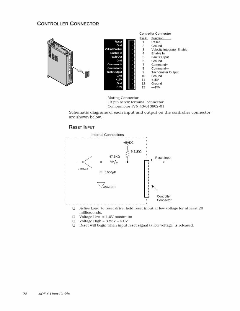
72 APEX User Guide
CONTROLLER CONNECTOR
Controller Connector
Pin #:12345678910111213
Function:ResetGroundVelocity Integrator EnableEnable In Fault OutputGroundCommand+Command—Tachometer OutputGround+15VGround—15V
ResetGnd
Vel Int EnableEnable InFault Out
GndCommand+Command -
Tach OutputGnd
+15VGnd-15V
A P E X 1 0
A P E X 1 0
Compumotor
Compumotor
Velocity Erro
r
Velocity Erro
r
Torque Cmd
Torque Cmd
Collectiv
e Gain
Collectiv
e Gain
Vel Integral G
ain
Vel Integral G
ain
Offset B
alance
Offset B
alance
Tach Out Cal
Tach Out Cal
Enable
Enable
Disable
Disable
Bridge Fault
Bridge Fault
Drive Fault
Drive Fault
Motor Fault
Motor Fault
Over Volta
ge
Over Volta
ge
I2T Lim
it
T Limit
Regen Fault
Regen Fault
Regen Active
Regen Active
ResetReset
GndGnd
Vel Int E
nable
Vel Int E
nable
Enable In
Enable In
Fault Out
Fault Out
GndGnd
Command+
Command+
Command -
Command -
Tach Output
Tach Output
GndGnd
+15V+15V
GndGnd
-15V-15V
CHA+CHA+
CHA -CHA -
CHB+CHB+
CHB -CHB -
CHZ+CHZ+
CHZ -CHZ -
GndGnd
ShieldShield
RedRed
BlackBlack
GreenGreen
BlueBlue
BrownBrown
WhiteWhite
Motor Temp+
Motor Temp+
Motor Temp -
Motor Temp -
Fault Relay+
Fault Relay+
Fault Relay -
Fault Relay -
Feedback+
Feedback+
Feedback -
Feedback -
DA
NG
ER
HIGH VOLTAGE
L1L2
Earth
Earth
Earth
Control L
1
Control L
2
Ref
Sin
Cos
Controller Connector
Mating Connector:13 pin screw terminal connectorCompumotor P/N 43-013802-01
Schematic diagrams of each input and output on the controller connectorare shown below.
RESET INPUT
6.81KΩ
Internal Connections
+5VDC
74HC14
Reset Input47.5KΩ
1000pF
ControllerConnector
1
ANA GND
Active Low: to reset drive, hold reset input at low voltage for at least 20milliseconds.
Voltage Low = 1.0V maximum Voltage High = 3.25V – 5.0V Reset will begin when input reset signal (a low voltage) is released.
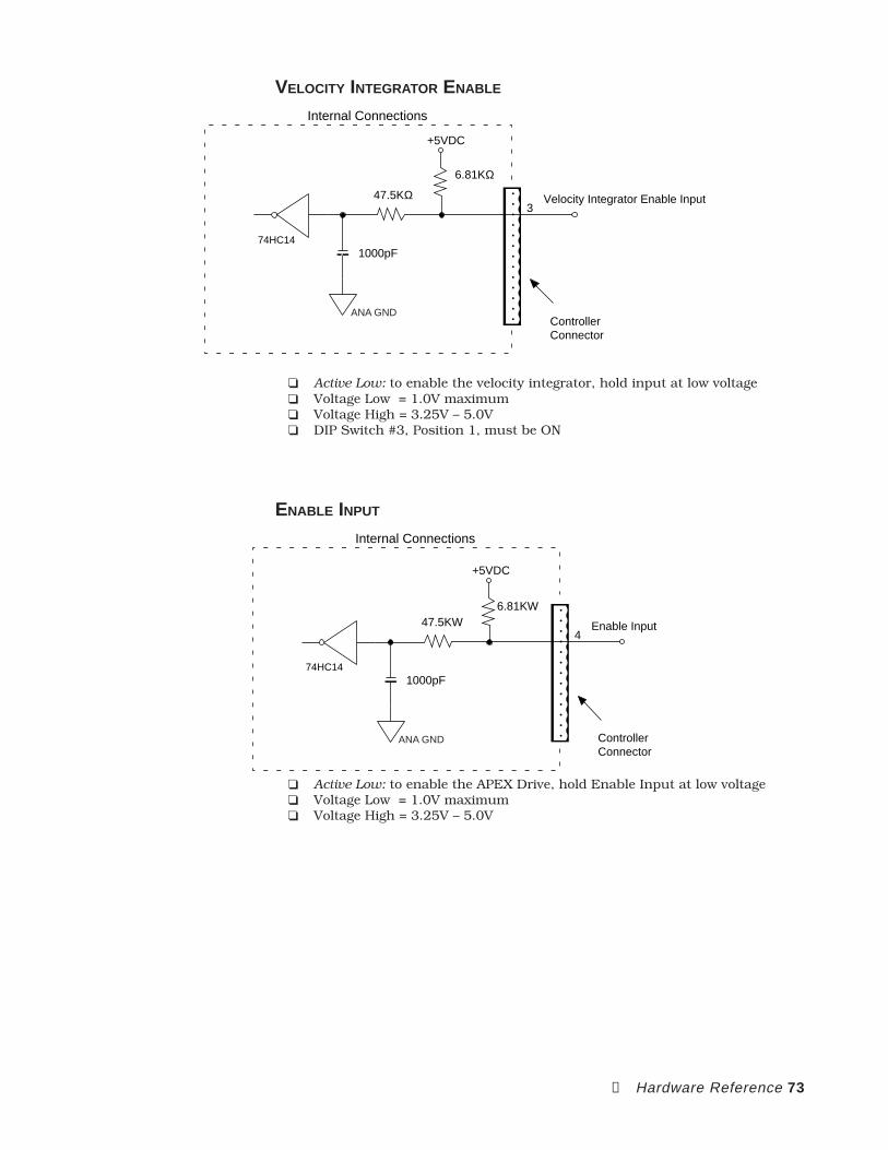
➃ Hardware Reference 73
VELOCITY INTEGRATOR ENABLE
6.81KΩ
Internal Connections
+5VDC
74HC14
Velocity Integrator Enable Input47.5KΩ
1000pF
ControllerConnector
3
ANA GND
Active Low: to enable the velocity integrator, hold input at low voltage Voltage Low = 1.0V maximum Voltage High = 3.25V – 5.0V DIP Switch #3, Position 1, must be ON
ENABLE INPUT
6.81KW
Internal Connections
+5VDC
74HC14
Enable Input47.5KW
1000pF
ControllerConnector
4
ANA GND
Active Low: to enable the APEX Drive, hold Enable Input at low voltage Voltage Low = 1.0V maximum Voltage High = 3.25V – 5.0V
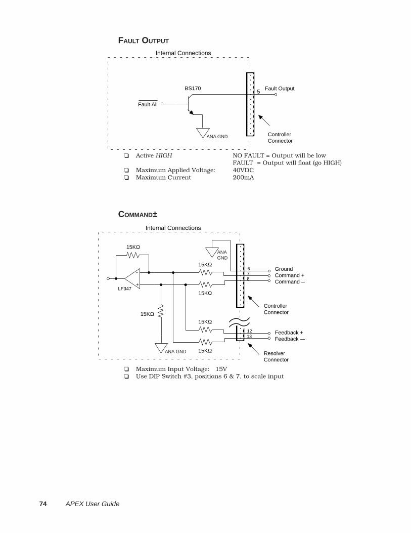
74 APEX User Guide
FAULT OUTPUT
Internal Connections
Fault Output
ControllerConnector
5
Fault All
BS170
ANA GND
Active HIGH NO FAULT = Output will be lowFAULT = Output will float (go HIGH)
Maximum Applied Voltage: 40VDC Maximum Current 200mA
COMMAND±Internal Connections
Command +
15KΩ78
Command —+
-
LF347
Ground6
ResolverConnector
15KΩ
Feedback +
15KΩ
1213 Feedback —
15KΩ
ControllerConnector
15KΩ
15KΩ
ANA GND
ANA GND
Maximum Input Voltage: 15V Use DIP Switch #3, positions 6 & 7, to scale input
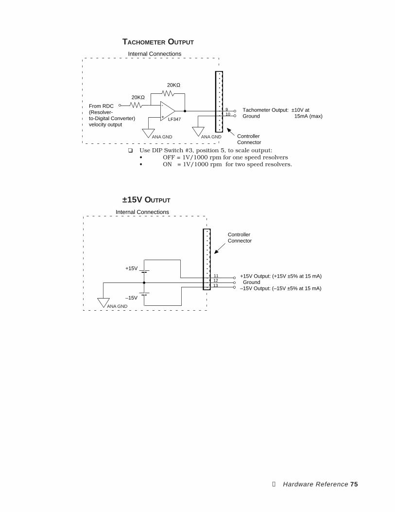
➃ Hardware Reference 75
TACHOMETER OUTPUT
Internal Connections
Tachometer Output: ±10V at
ControllerConnector
910
+
-
LF347
From RDC(Resolver-to-Digital Converter)velocity output
Ground 15mA (max)
20KΩ
20KΩ
ANA GND ANA GND
Use DIP Switch #3, position 5, to scale output:• OFF = 1V/1000 rpm for one speed resolvers• ON = 1V/1000 rpm for two speed resolvers.
±15V OUTPUT
Internal Connections
Ground1213
–15V Output: (–15V ±5% at 15 mA)
+15V Output: (+15V ±5% at 15 mA)11
ControllerConnector
+15V
–15V
ANA GND
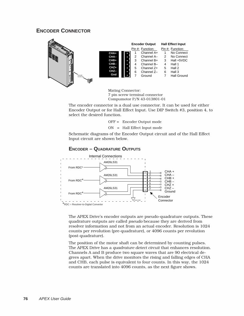
76 APEX User Guide
ENCODER CONNECTOR
CHA+CHA–CHB+CHB–CHZ+CHZ–
Gnd
Encoder Output
Pin #:1234567
Function:Channel A+Channel A–Channel B+Channel B–Channel Z+Channel Z–Ground
Hall Effect Input
Pin #:1234567
Function:No ConnectNo ConnectHall +5VDCHall 1Hall 2Hall 3Hall Ground
A P E X 1 0
Compumotor
Compumotor
Velocity Erro
r
Velocity Erro
r
Torque Cmd
Torque Cmd
Collective G
ain
Collective G
ain
Vel Integral G
ain
Vel Integral G
ain
Offset B
alance
Offset B
alance
Tach O
ut Cal
Tach O
ut Cal
EnableEnable
Disable
Disable
Bridge Fault
Bridge Fault
Drive Fault
Drive Fault
Motor Fault
Motor Fault
Over V
oltage
Over V
oltage
I2T Lim
it
T Limit
Regen Fault
Regen Fault
Regen Active
Regen Active
Reset
Reset
GndGnd
Vel Int E
nable
Vel Int E
nable
Enable In
Enable In
Fault Out
Fault Out
GndGnd
Command+
Command+
Command -
Command -
Tach O
utput
Tach O
utput
GndGnd
+15V
GndGnd
-15V
CHA+CHA+
CHA -CHA -
CHB+CHB+
CHB -CHB -
CHZ+CHZ+
CHZ -CHZ -
GndGnd
ShieldShield
RedRed
BlackBlack
GreenGreen
BlueBlue
BrownBrown
WhiteWhite
Motor Temp+
Motor Temp+
Motor Temp -
Motor Temp -
Fault Relay+
Fault Relay+
Fault Relay -
Fault Relay -
Feedback+
Feedback+
Feedback -
Feedback -
DA
NG
ER
HIGH VOLTAGE
L1L2
Earth
Earth
Earth
Control L
1
Control L
2
Ref
Sin
Cos
Encoder Connector
Mating Connector:7 pin screw terminal connectorCompumotor P/N 43-013801-01
The encoder connector is a dual use connector. It can be used for eitherEncoder Output or for Hall Effect Input. Use DIP Switch #3, position 4, toselect the desired function.
OFF = Encoder Output mode
ON = Hall Effect Input mode
Schematic diagrams of the Encoder Output circuit and of the Hall EffectInput circuit are shown below.
ENCODER – QUADRATURE OUTPUTS
Internal Connections
CHA –23 CHB +
CHA +1
From RDC*
From RDC*
4567
CHB –CHZ +CHZ –Ground
EncoderConnector
AM26LS31
AM26LS31
AM26LS31
From RDC*
ANA GND
*RDC = Resolver-to-Digital Converter
The APEX Drive’s encoder outputs are pseudo-quadrature outputs. Thesequadrature outputs are called pseudo because they are derived fromresolver information and not from an actual encoder. Resolution is 1024counts per revolution (pre-quadrature), or 4096 counts per revolution(post-quadrature).
The position of the motor shaft can be determined by counting pulses.The APEX Drive has a quadrature detect circuit that enhances resolution.Channels A and B produce two square waves that are 90 electrical de-grees apart. When the drive monitors the rising and falling edges of CHAand CHB, each pulse is equivalent to four counts. In this way, the 1024counts are translated into 4096 counts, as the next figure shows.
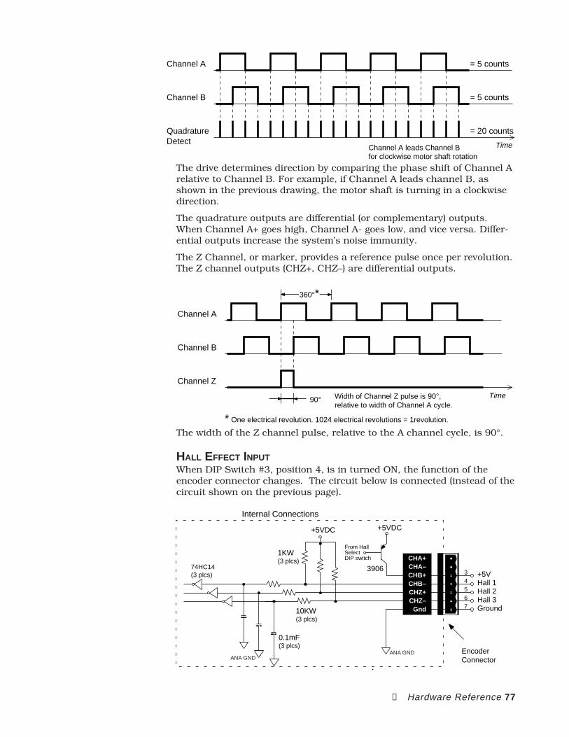
➃ Hardware Reference 77
Channel A
Channel B
QuadratureDetect Time
= 5 counts
= 5 counts
= 20 counts
Channel A leads Channel Bfor clockwise motor shaft rotation
The drive determines direction by comparing the phase shift of Channel Arelative to Channel B. For example, if Channel A leads channel B, asshown in the previous drawing, the motor shaft is turning in a clockwisedirection.
The quadrature outputs are differential (or complementary) outputs.When Channel A+ goes high, Channel A- goes low, and vice versa. Differ-ential outputs increase the system’s noise immunity.
The Z Channel, or marker, provides a reference pulse once per revolution.The Z channel outputs (CHZ+, CHZ–) are differential outputs.
Channel A
Channel B
Channel Z
Width of Channel Z pulse is 90°,relative to width of Channel A cycle.
360°*
90° Time
* One electrical revolution. 1024 electrical revolutions = 1revolution.
The width of the Z channel pulse, relative to the A channel cycle, is 90°.
HALL EFFECT INPUTWhen DIP Switch #3, position 4, is in turned ON, the function of theencoder connector changes. The circuit below is connected (instead of thecircuit shown on the previous page).
1KW(3 plcs)
+5VDC
74HC14(3 plcs)
10KW(3 plcs)
0.1mF(3 plcs)
Internal Connections
EncoderConnector
34
3906
From HallSelectDIP switch
+5VDC
567
+5VHall 1Hall 2Hall 3Ground
CHA+CHA–CHB+CHB–CHZ+CHZ–
Gnd
ANA GNDANA GND
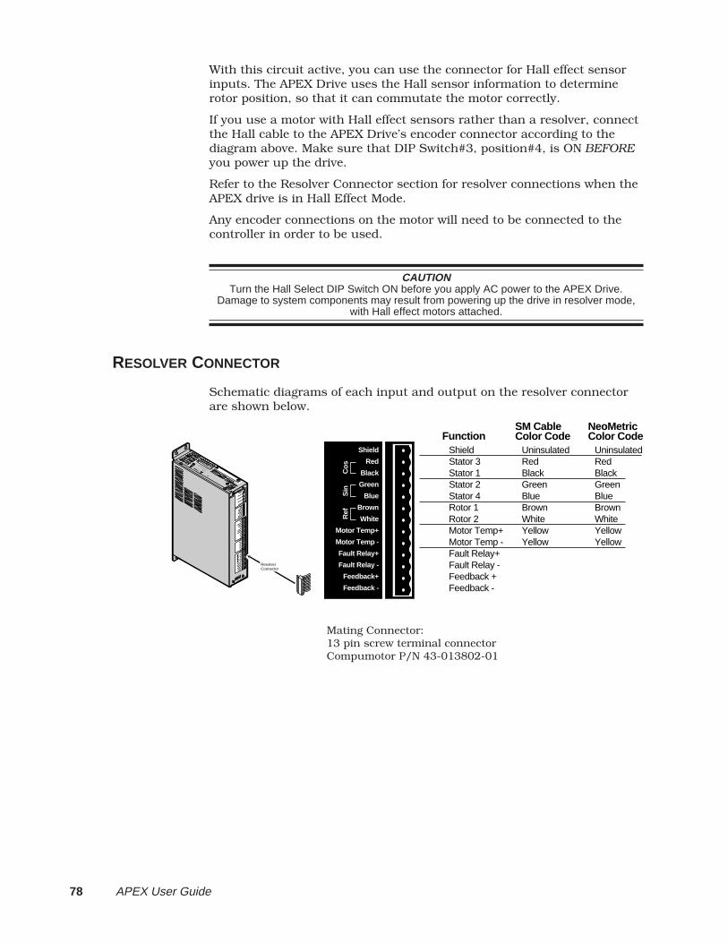
78 APEX User Guide
With this circuit active, you can use the connector for Hall effect sensorinputs. The APEX Drive uses the Hall sensor information to determinerotor position, so that it can commutate the motor correctly.
If you use a motor with Hall effect sensors rather than a resolver, connectthe Hall cable to the APEX Drive’s encoder connector according to thediagram above. Make sure that DIP Switch#3, position#4, is ON BEFOREyou power up the drive.
Refer to the Resolver Connector section for resolver connections when theAPEX drive is in Hall Effect Mode.
Any encoder connections on the motor will need to be connected to thecontroller in order to be used.
CAUTIONTurn the Hall Select DIP Switch ON before you apply AC power to the APEX Drive.
Damage to system components may result from powering up the drive in resolver mode,with Hall effect motors attached.
RESOLVER CONNECTOR
Schematic diagrams of each input and output on the resolver connectorare shown below.
ShieldStator 3Stator 1Stator 2Stator 4Rotor 1Rotor 2Motor Temp+Motor Temp -Fault Relay+Fault Relay -Feedback +Feedback -
FunctionUninsulatedRedBlackGreenBlueBrownWhiteYellowYellow
SM CableColor Code
UninsulatedRedBlackGreenBlueBrownWhiteYellowYellow
NeoMetricColor Code
Shield
Red
Black
Green
Blue
Brown
White
Motor Temp+
Motor Temp -
Fault Relay+
Fault Relay -
Feedback+
Feedback -
Ref
Sin
Cos
A P E X 1 0
Compumotor
Compumotor
Velocity Erro
r
Velocity Erro
r
Torque Cmd
Torque Cmd
Collective G
ain
Collective G
ain
Vel Integral G
ain
Vel Integral G
ain
Offset B
alance
Offset B
alance
Tach O
ut Cal
Tach O
ut Cal
EnableEnable
Disable
Disable
Bridge Fault
Bridge Fault
Drive Fault
Drive Fault
Motor Fault
Motor Fault
Over V
oltage
Over V
oltage
I2T Lim
it
T Limit
Regen Fault
Regen Fault
Regen Active
Regen Active
Reset
Reset
GndGnd
Vel Int E
nable
Vel Int E
nable
Enable In
Enable In
Fault Out
Fault Out
GndGnd
Command+
Command+
Command -
Command -
Tach O
utput
Tach O
utput
GndGnd
+15V+15V
GndGnd
-15V-15V
CHA+CHA+
CHA -CHA -
CHB+CHB+
CHB -CHB -
CHZ+CHZ+
CHZ -CHZ -
GndGnd
ShieldShield
RedRed
BlackBlack
GreenGreen
BlueBlue
BrownBrown
WhiteWhite
Motor Temp+
Motor Temp+
Motor Temp -
Motor Temp -
Fault Relay+
Fault Relay+
Fault Relay -
Fault Relay -
Feedback+
Feedback+
Feedback -
Feedback -
DA
NG
ER
HIGH VOLTAGE
L1L2
Earth
Earth
Earth
Control L
1
Control L
2
Ref
Ref
Sin
Sin
Cos
Cos
Resolver Connector
Mating Connector:13 pin screw terminal connectorCompumotor P/N 43-013802-01

➃ Hardware Reference 79
Internal Connections
Stator 323 Stator 1
Ground (for cable shield)1
ResolverConnector
1:1
1:1
1:14.25V rms ± 5%at 7 kHz ± 5% (sine wave)
To RDC*
To RDC*
4567
Stator 2Stator 4Rotor 1Rotor 2
Stator Input Voltage: 2V r ms ± 5%
ANA GND
*Resolver-to-Digital Converter
DIP Switch #3, position 4, must be OFF so that:• Internal microprocessor uses resolver information for commu-
tation• Encoder output will be enabled• Hall Effect input will be disabled
Shield (on the resolver connector) is internally connected to all groundterminals (labeled Gnd ) on the APEX Drive’s front panel. These terminals areisolated from Earth and Motor Ground , and from the chassis.
MOTOR TEMP±
10KΩ
Internal Connections
+5VDC
74HC14 0.1µF
ResolverConnector
89
Motor Temperature +Motor Temperature –
10KΩ
ANA GND ANA GND
Motor's temperature sensor should be normally closed (closed at low tem-peratures; opens at high temperatures.)
Short together Motor Temp+ and Motor Temp- if motor does not have atemperature sensor.
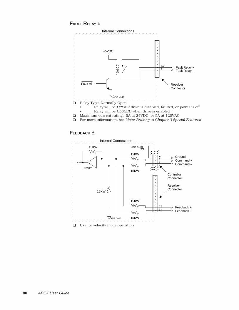
80 APEX User Guide
FAULT RELAY ±
Internal Connections
ResolverConnector
Fault Relay +Fault Relay –
1011
+5VDC
Fault All
ANA GND
Relay Type: Normally Open• Relay will be OPEN if drive is disabled, faulted, or power is off• Relay will be CLOSED when drive is enabled
Maximum current rating: 5A at 24VDC, or 5A at 120VAC For more information, see Motor Braking in Chapter 3 Special Features
FEEDBACK ±
Internal Connections
Command +
15KW
78
Command –+
-
LF347
Ground6
ResolverConnector
15KW
Feedback +
15KW
1213 Feedback –
15KW
ControllerConnector
15KW
15KW
ANA GND
ANA GND
Use for velocity mode operation
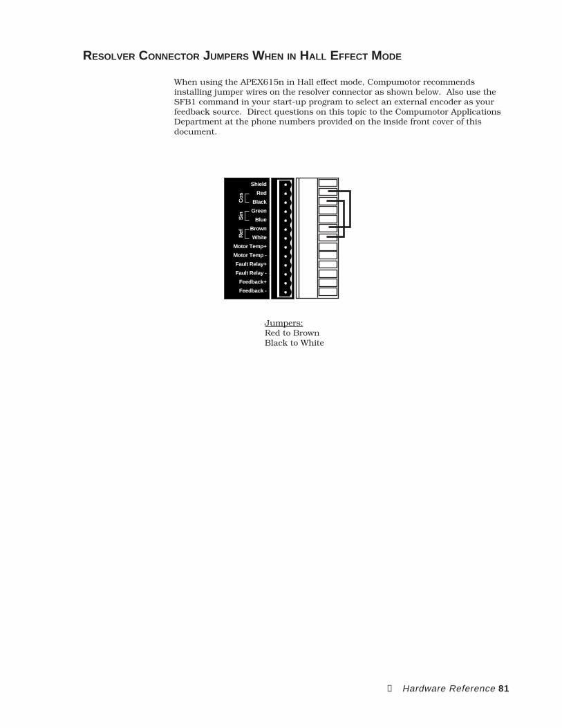
➃ Hardware Reference 81
RESOLVER CONNECTOR JUMPERS WHEN IN HALL EFFECT MODE
When using the APEX615n in Hall effect mode, Compumotor recommendsinstalling jumper wires on the resolver connector as shown below. Also use theSFB1 command in your start-up program to select an external encoder as yourfeedback source. Direct questions on this topic to the Compumotor ApplicationsDepartment at the phone numbers provided on the inside front cover of thisdocument.
Shield
Red
Black
Green
Blue
Brown
White
Motor Temp+
Motor Temp -
Fault Relay+
Fault Relay -
Feedback+
Feedback -
Ref
Sin
Cos
Jumpers:Red to BrownBlack to White
82 APEX User Guide
MOTOR SPECIFICATIONS
Speed/torque curves, motor specifications, and dimensions are shown onthe following pages.
MOTOR BRAKES
Optional motor brakes are available. They are mounted directly behindthe motor and are pre-assembled at the factory. When ordering the brakeoption, specify the motor type.
Brakes 70mm or 34 frame 92mm
Static rated torque 24 in-lb 72 in-lb
Coil voltage 24 VDC 24 VDC
Coil current 0.8 amps 0.52 amps
Weight 1.0 lbbs 2.51 lbs
Inertia 0.000038 lbs-in-sec2 0.00015 lb-in-sec2
MOTOR CABLES
SM and NeoMetric cables are available in 10, 25, and 35 foot lengths;APEX motor cables are available in 25, 50, and 100 foot lengths. You canalso order custom cables of any length. Call Compumotor’s CustomerService Department (800-722-2282). Cable lengths in excess of 100 feetare not recommended.
MOTOR DATA
The data sheets do not assume operation from an APEX drive. The torquespecifications reflect the motor’s capabilities. In most cases, the motorwindings match the drive’s output power with an additional safetymargin.
POSITIONAL REPEATABILITY
Repeatability : ±0.088 degrees, unloaded
POSITIONAL ACCURACY
Resolver Accuracy : ±10 arc minutes
Resolver-to-Digital Converter Accuracy : ±10 arc minutes
RESOLUTION
Resolver : 4096 counts/rev
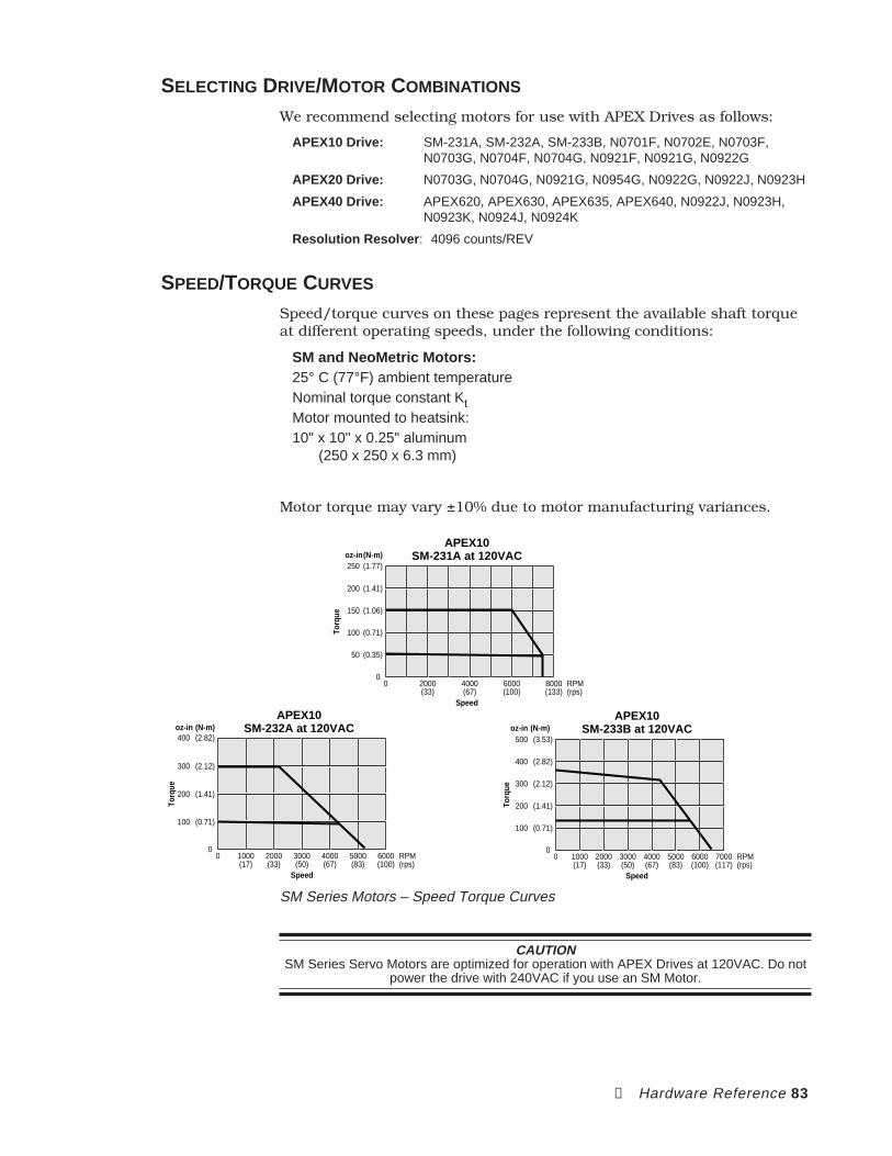
➃ Hardware Reference 83
SELECTING DRIVE/MOTOR COMBINATIONS
We recommend selecting motors for use with APEX Drives as follows:
APEX10 Drive: SM-231A, SM-232A, SM-233B, N0701F, N0702E, N0703F,N0703G, N0704F, N0704G, N0921F, N0921G, N0922G
APEX20 Drive: N0703G, N0704G, N0921G, N0954G, N0922G, N0922J, N0923H
APEX40 Drive: APEX620, APEX630, APEX635, APEX640, N0922J, N0923H,N0923K, N0924J, N0924K
Resolution Resolver : 4096 counts/REV
SPEED/TORQUE CURVES
Speed/torque curves on these pages represent the available shaft torqueat different operating speeds, under the following conditions:
SM and NeoMetric Motors:25° C (77°F) ambient temperatureNominal torque constant KtMotor mounted to heatsink:10" x 10" x 0.25" aluminum
(250 x 250 x 6.3 mm)
Motor torque may vary ±10% due to motor manufacturing variances.
Speed
Torq
ue
APEX10SM-231A at 120VAC
00 8000
(133)
oz-in(N-m)(1.77)250
(0.35)50
6000(100)
4000(67)
2000(33)
RPM(rps)
(0.71)100
(1.06)150
(1.41)200
Speed
Torq
ue
APEX10SM-232A at 120VAC
00 6000
(100)
oz-in (N-m)
RPM(rps)
(2.82)400
(2.12)300
(1.41)200
(0.71)100
5000(83)
4000(67)
3000(50)
2000(33)
1000(17)
Speed
Torq
ue
APEX10SM-233B at 120VAC
00
(3.53)oz-in (N-m)
500
(2.82)400
(2.12)300
(1.41)200
(0.71)100
7000(117)
RPM(rps)
6000(100)
5000(83)
4000(67)
3000(50)
2000(33)
1000(17)
SM Series Motors – Speed Torque Curves
CAUTIONSM Series Servo Motors are optimized for operation with APEX Drives at 120VAC. Do not
power the drive with 240VAC if you use an SM Motor.
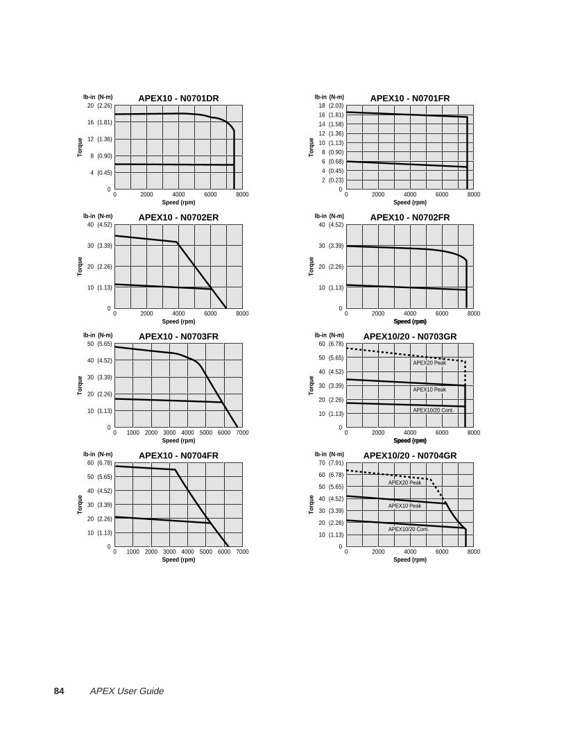
84 APEX User Guide
Speed (rpm)
Torq
ue
APEX10 - N0701DR
00 8000
(2.26)lb-in (N-m)
20
Speed (rpm)
Torq
ue
APEX10 - N0701FR
00 8000
(2.03)lb-in (N-m)
18
Speed (rpm)
Torq
ue
APEX10 - N0702FR
00 8000
lb-in (N-m)
Speed (rpm)
Torq
ue
APEX10 - N0702ER
00 8000
(4.52)lb-in (N-m)
40
Speed (rpm)
Speed (rpm)
Torq
ue
APEX10/20 - N0703GR
00
lb-in (N-m)
Speed (rpm)
Torq
ue
APEX10 - N0703FR
00 7000
(5.65)lb-in (N-m)
50
Speed (rpm)
Speed (rpm)
Torq
ue
APEX10/20 - N0704GR
00 8000
(7.91)lb-in (N-m)
70
Speed (rpm)
Torq
ue
APEX10 - N0704FR
00 7000
(6.78)lb-in (N-m)
60
(1.81)16
(1.36)12
(0.90)8
(0.45)4
600040002000
(1.81)16
(1.58)14
(1.36)12
(1.13)10
(0.90)8
(0.68)6
(0.45)4
(0.23)2
600040002000
(3.39)30
(2.26)20
(1.13)10
600040002000 600040002000
(4.52)40
(3.39)30
(2.26)20
(1.13)10
600050004000300020001000 8000600040002000
(5.65)50
(4.52)40
(3.39)30
(2.26)20
(1.13)10
600050004000300020001000 600040002000
(4.52)40
(3.39)30
(2.26)20
(1.13)10
(6.78)60
(5.65)50
(4.52)40
(3.39)30
(2.26)20
(1.13)10
APEX20 Peak
APEX10 Peak
APEX10/20 Cont.
(6.78)60
(5.65)50
(4.52)40
(3.39)30
(2.26)20
(1.13)10
APEX20 Peak
APEX10 Peak
APEX10/20 Cont.
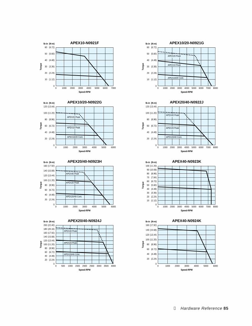
➃ Hardware Reference 85
Torq
ue
0 7000
APEX10-N0921F
Speed-RPM
0
60
lb-in
(6.72)
(N-m)
600050004000300020001000
50 (5.60)
40 (4.48)
30 (3.36)
20 (2.24)
10 (1.12)
Torq
ue
0 8000
APEX10/20-N0921G
7000600050004000300020001000
Speed-RPM
0
60
lb-in
(6.72)
(N-m)
50 (5.60)
40 (4.48)
30 (3.36)
20 (2.24)
10 (1.12)
APEX20 Peak
APEX10 Peak
APEX10/20 Cont.
Torq
ue
0 6000
APEX10/20-N0922G
0
120
lb-in
(13.44)
(N-m)
50004000300020001000
100 (11.20)
80 (8.96)
60 (6.72)
40 (4.48)
20 (2.24)
Speed-RPM
APEX20 Peak
APEX10 Peak
APEX10/20 Cont.
Torq
ue
0 8000
APEX20/40-N0922J
0
120
lb-in
(13.44)
(N-m)
7000600050004000300020001000
100 (11.20)
80 (8.96)
60 (6.72)
40 (4.48)
20 (2.24)
Speed-RPM
APEX40 Peak
APEX20 Peak
APEX20/40 Cont.
0
160
lb-in
(17.92)
(N-m)
Torq
ue
0 6000
APEX20/40-N0923H
50004000300020001000
140 (15.68)
120 (13.44)
100 (11.20)
80 (8.96)
60 (6.72)
40 (4.48)
20 (2.24)
Speed-RPM
APEX40 Peak
APEX20 Peak
APEX20/40 Cont.
Torq
ue
0 8000
APEX40-N0923K
0
100
lb-in
(11.20)
(N-m)
90 (10.08)
80 (8.96)
70 (7.84)
60 (6.72)
50 (5.60)
40 (4.48)
30 (3.36)
20 (2.24)
10 (1.12)
7000600050004000300020001000
Speed-RPM
Torq
ue
0 4000
APEX20/40-N0924J
0
200
lb-in
(22.40)
(N-m)
350030002500200015001000500
180 (20.16)
160 (17.92)
140 (15.68)
120 (13.44)
100 (11.20)
80 (8.96)
60 (6.72)
40 (4.48)
20 (2.24)
Speed-RPM
APEX40 Peak
APEX20 Peak
APEX20/40 Cont.
0
Torq
ue
160
lb-in
(17.92)
(N-m)
0 6000
APEX40-N0924K
140 (15.68)
120 (13.44)
100 (11.20)
80 (8.96)
60 (6.72)
40 (4.48)
20 (2.24)
50004000300020001000
Speed-RPM
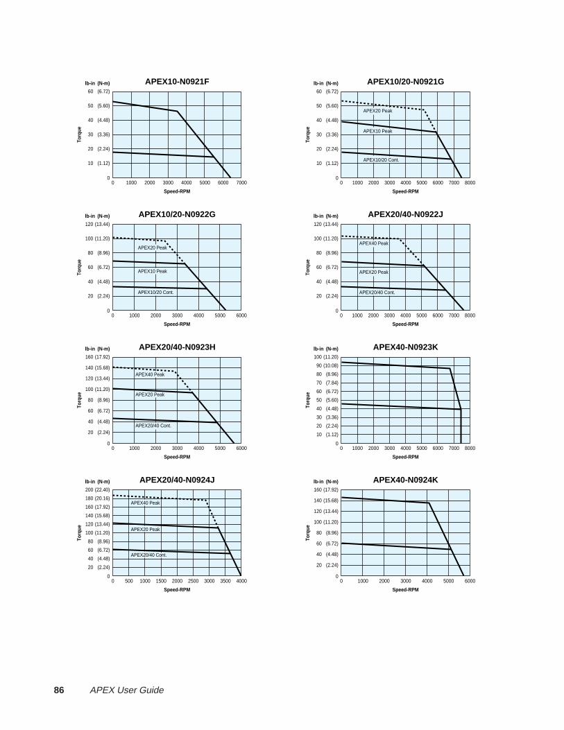
86 APEX User Guide
Torq
ue
0 7000
APEX10-N0921F
Speed-RPM
0
60
lb-in
(6.72)
(N-m)
600050004000300020001000
50 (5.60)
40 (4.48)
30 (3.36)
20 (2.24)
10 (1.12)
Torq
ue
0 8000
APEX10/20-N0921G
7000600050004000300020001000
Speed-RPM
0
60
lb-in
(6.72)
(N-m)
50 (5.60)
40 (4.48)
30 (3.36)
20 (2.24)
10 (1.12)
APEX20 Peak
APEX10 Peak
APEX10/20 Cont.
Torq
ue
0 6000
APEX10/20-N0922G
0
120
lb-in
(13.44)
(N-m)
50004000300020001000
100 (11.20)
80 (8.96)
60 (6.72)
40 (4.48)
20 (2.24)
Speed-RPM
APEX20 Peak
APEX10 Peak
APEX10/20 Cont.
Torq
ue
0 8000
APEX20/40-N0922J
0
120
lb-in
(13.44)
(N-m)
7000600050004000300020001000
100 (11.20)
80 (8.96)
60 (6.72)
40 (4.48)
20 (2.24)
Speed-RPM
APEX40 Peak
APEX20 Peak
APEX20/40 Cont.
0
160
lb-in
(17.92)
(N-m)
Torq
ue
0 6000
APEX20/40-N0923H
50004000300020001000
140 (15.68)
120 (13.44)
100 (11.20)
80 (8.96)
60 (6.72)
40 (4.48)
20 (2.24)
Speed-RPM
APEX40 Peak
APEX20 Peak
APEX20/40 Cont.
Torq
ue
0 8000
APEX40-N0923K
0
100
lb-in
(11.20)
(N-m)
90 (10.08)
80 (8.96)
70 (7.84)
60 (6.72)
50 (5.60)
40 (4.48)
30 (3.36)
20 (2.24)
10 (1.12)
7000600050004000300020001000
Speed-RPM
Torq
ue
0 4000
APEX20/40-N0924J
0
200
lb-in
(22.40)
(N-m)
350030002500200015001000500
180 (20.16)
160 (17.92)
140 (15.68)
120 (13.44)
100 (11.20)
80 (8.96)
60 (6.72)
40 (4.48)
20 (2.24)
Speed-RPM
APEX40 Peak
APEX20 Peak
APEX20/40 Cont.
0
Torq
ue
160
lb-in
(17.92)
(N-m)
0 6000
APEX40-N0924K
140 (15.68)
120 (13.44)
100 (11.20)
80 (8.96)
60 (6.72)
40 (4.48)
20 (2.24)
50004000300020001000
Speed-RPM
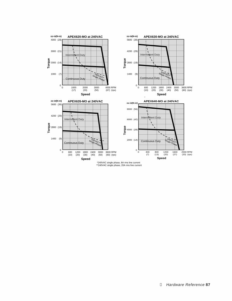
➃ Hardware Reference 87
APEX630-MO at 240VAC
Speed
To
rqu
e
600(10)
1200(20)
1800(30)
2400(40)
3000(50)
RPM(rps)
5600
4200
2800
1400
(39)
(29)
(19)
(9)
0
oz-in(N-m)
0 3600(60)
APEX635-MO at 240VAC
Speed
To
rqu
e
600(10)
1200(20)
1800(30)
2400(40)
3000(50)
RPM(rps)
5600
4200
2800
1400
(39)
(29)
(19)
(9)
0
oz-in(N-m)
0 3600(60)
APEX640-MO at 240VAC
Speed
Torq
ue
400(7)
800(13)
1200(20)
1600(27)
RPM(rps)
8000
6000
4000
2000
(56)
(42)
(28)
(14)
0
oz-in(N-m)
0 2000(33)
*240VAC single phase, 8A rms line current**240VAC single phase, 20A rms line current
APEX620-MO at 240VAC
Speed
To
rqu
e
1000(17)
2000(33)
3000(50)
4000(67)
RPM(rps)
4000
3000
2000
1000
(28)
(21)
(14)
(7)
0
oz-in(N-m)
0
Intermittent Duty
Continuous Duty
Intermittent Duty
Continuous Duty
240VAC**Single Phase
Intermittent Duty
Continuous Duty
Intermittent Duty
Continuous Duty
240VAC**Single Phase
240VAC**Single Phase
240VAC**Single Phase
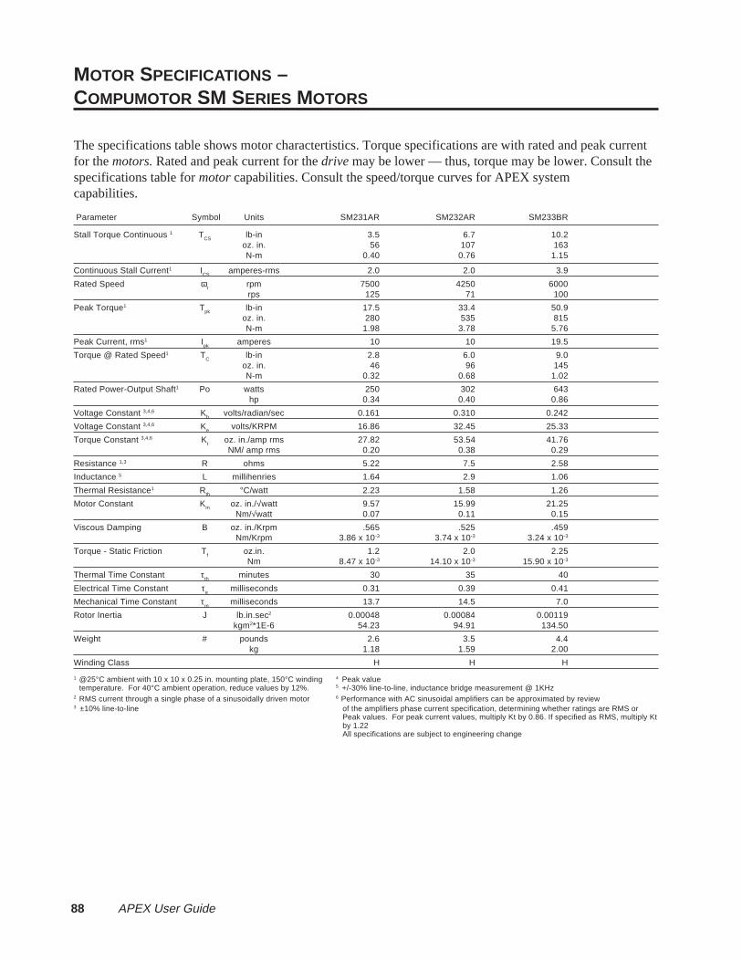
88 APEX User Guide
MOTOR SPECIFICATIONS –COMPUMOTOR SM SERIES MOTORS
The specifications table shows motor charactertistics. Torque specifications are with rated and peak currentfor the motors. Rated and peak current for the drive may be lower — thus, torque may be lower. Consult thespecifications table for motor capabilities. Consult the speed/torque curves for APEX systemcapabilities.
Parameter Symbol Units SM231AR SM232AR SM233BR
Stall Torque Continuous 1 TCS lb-in 3.5 6.7 10.2oz. in. 56 107 163N-m 0.40 0.76 1.15
Continuous Stall Current1 ICS
amperes-rms 2.0 2.0 3.9
Rated Speed ωr rpm 7500 4250 6000rps 125 71 100
Peak Torque1 Tpk lb-in 17.5 33.4 50.9oz. in. 280 535 815N-m 1.98 3.78 5.76
Peak Current, rms1 Ipk
amperes 10 10 19.5
Torque @ Rated Speed1 TC
lb-in 2.8 6.0 9.0oz. in. 46 96 145N-m 0.32 0.68 1.02
Rated Power-Output Shaft1 Po watts 250 302 643hp 0.34 0.40 0.86
Voltage Constant 3,4,6 Kb volts/radian/sec 0.161 0.310 0.242
Voltage Constant 3,4,6 Ke volts/KRPM 16.86 32.45 25.33
Torque Constant 3,4,6 Kt
oz. in./amp rms 27.82 53.54 41.76NM/ amp rms 0.20 0.38 0.29
Resistance 1,3 R ohms 5.22 7.5 2.58
Inductance 5 L millihenries 1.64 2.9 1.06
Thermal Resistance1 Rth °C/watt 2.23 1.58 1.26
Motor Constant Km oz. in./√watt 9.57 15.99 21.25Nm/√watt 0.07 0.11 0.15
Viscous Damping B oz. in./Krpm .565 .525 .459Nm/Krpm 3.86 x 10⁻³ 3.74 x 10⁻³ 3.24 x 10⁻³
Torque - Static Friction Tf
oz.in. 1.2 2.0 2.25Nm 8.47 x 10⁻³ 14.10 x 10⁻³ 15.90 x 10⁻³
Thermal Time Constant τth
minutes 30 35 40
Electrical Time Constant τe milliseconds 0.31 0.39 0.41
Mechanical Time Constant τm
milliseconds 13.7 14.5 7.0
Rotor Inertia J lb.in.sec2 0.00048 0.00084 0.00119kgm2*1E-6 54.23 94.91 134.50
Weight # pounds 2.6 3.5 4.4kg 1.18 1.59 2.00
Winding Class H H H
1 @25°C ambient with 10 x 10 x 0.25 in. mounting plate, 150°C winding 4 Peak valuetemperature. For 40°C ambient operation, reduce values by 12%. 5 +/-30% line-to-line, inductance bridge measurement @ 1KHz
2 RMS current through a single phase of a sinusoidally driven motor 6 Performance with AC sinusoidal amplifiers can be approximated by review3 ±10% line-to-line of the amplifiers phase current specification, determining whether ratings are RMS or
Peak values. For peak current values, multiply Kt by 0.86. If specified as RMS, multiply Kt by 1.22 All specifications are subject to engineering change

➃ Hardware Reference 89
MOTOR SPECIFICATIONS –COMPUMOTOR 70MM (34FRAME) NEOMETRIC SERIES MOTORS
The specifications table shows motor charactertistics. Torque specifications are with rated and peak currentfor the motors. Rated and peak current for the drive may be lower — thus, torque may be lower. Consult thespecifications table for motor capabilities. Consult the speed/torque curves for APEX systemcapabilities.
Parameter Symbol Units N0701DR N0701FR N0702ER N0702FR N0703FR N0703GR N0704FR N0704GR
Stall Torque Continuous 1,2 TCS
lb-in 6.40 6.40 11.90 11.90 18.00 18.00 22.20 22.20N-m 0.72 0.72 1.34 1.34 2.03 2.03 2.50 2.50
Continuous Stall Current1 ICS
amperes-rms 2.65 4.14 3.05 4.24 4.17 5.79 4.30 5.96
Rated Speed ωr
rpm 7,500 7,500 6,480 7,500 5,800 7,500 4,900 7,000rps 125 125 108 125 98 125 82 117
Peak Torque1 Tpk lb-in 19.20 19.20 35.60 35.60 54.00 54.00 66.60 66.60N-m 2.17 2.17 4.02 4.02 6.10 6.10 7.50 7.50
Peak Current, rms1,6 Ipk amperes 7.90 12.40 9.10 12.70 12.50 17.40 12.90 17.90
Torque @ Rated Speed1 TC
lb-in 5.80 5.80 9.40 10.40 14.50 15.40 17.50 17.50N-m 0.66 0.66 1.06 1.18 1.64 1.74 1.98 1.98
Rated Power-Output Shaft1 Po watts 510 515 718 919 1,004 1,367 1,014 1,450
Voltage Constant 3,4 Kb
volts/radian/sec 0.221 0.14 0.353 0.253 0.392 0.282 0.468 0.338
Voltage Constant 3,4 Ke volts/KRPM 23.11 14.67 36.97 26.52 40.99 29.54 49.02 35.36
Torque Constant 3,4 Kt lb-in/amp rms 2.43 1.55 3.89 2.80 4.32 3.11 5.17 3.73
Resistance 3 R ohms 5.52 2.27 5.22 2.70 3.36 1.74 3.47 1.80
Inductance 3 L millihenries 12.98 5.23 15.86 8.16 12.13 6.30 14.50 7.55
Thermal Resistance1 Rth °C/watt 1.44 1.44 1.15 1.15 0.96 0.96 0.87 0.87
Motor Constant Km lb-in/√watt 0.83 1.03 1.70 1.70 2.36 2.36 2.77 2.78
Viscous Damping B lb-in/Krpm 0.0438 0.0438 0.050 0.050 0.0563 0.0563 0.0625 0.0625
Torque - Static Friction Tf
oz.in. 1.40 2.10 2.10 2.80 2.80 2.80 3.50 3.50
Thermal Time Constant 7 τth minutes 45 45 45 45 45 45 45 45
Electrical Time Constant τe milliseconds 2.35 2.35 3.03 3.03 3.61 3.61 4.19 4.19
Mechanical Time Constant τm
milliseconds 1.60 1.60 0.88 0.88 0.62 0.62 0.56 0.56
Rotor Inertia J lb.in.sec2 0.000128 0.000128 0.000196 0.000196 0.000262 0.000262 0.000329 0.000329
Weight # pounds 3.54 3.54 4.53 4.53 6.04 6.04 7.28 7.28
Winding Class H H H H H H H H
1 @25°C ambient with 10 x 10 x 0.25 in. mounting plate, 150°C winding 5 +/-30% line-t0-line, inductance bridge measurement @ 1KHztemperature. For 40°C ambient operation, reduce values by 12% 6 Peak current for 2 seconds maximum with initial winding temperature of 40° C.
2 RMS current through a single phase of a sinusoidally driven motor 7 Per NEMA specifications. For I2t considerations, use 10 minutes.3 ±10%, line-to-line, inductance bridge measurement method @ 1 kHz All specifications are subject to engineering change4 Peak value

90 APEX User Guide
MOTOR SPECIFICATIONS –COMPUMOTOR 92MM NEOMETRIC SERIES MOTORS
The specifications table shows motor charactertistics. Torque specifications are with rated and peak currentfor the motors. Rated and peak current for the drive may be lower — thus, torque may be lower. Consult thespecifications table for motor capabilities. Consult the speed/torque curves for APEX system capabilities.
Parameter Symbol Units N0921F N0921G N0922G N0922J N0923H N0923K N0924J N0924K
Stall Torque Continuous 1,4 TCS
lb-in 17.7 17.7 34.3 34.3 46.6 46.6 62.5 62.5N-m 2.0 2.0 3.88 3.88 5.26 5.26 7.06 7.06
Continuous Stall Current1,2 ICS
amperes-rms 3.77 5.22 5.6 8.67 7.89 13.85 8.64 12.07
Rated Speed ωr
rpm 5,700 7,500 4.375 6,975 4,350 7,500 3,325 4,825rps 95 125 72.9 116.2 72.5 125 55.4 80.4
Peak Torque1 Tpk
lb-in 53 53 103 103 140 140 188 188N-m 5.99 5.99 11.6 11.6 15.8 15.8 21.2 21.2
Peak Current, rms1,6 Ipk amperes 11.3 15.7 16.8 26 23.7 41.6 25.9 36.2
Torque @ Rated Speed1 TC
lb-in 14.0 14.7 27.0 27.0 36.2 36.3 49 47.7N-m 1.58 1.66 3.05 3.05 4.09 4.1 5.5 5.39
Rated Power-Output Shaft1 Po watts 946 1,305 1,397 2,231 1,864 3,222 1,930 2,731
Voltage Constant 3,4 Kb
volts/radian/sec 0.427 0.309 0.556 0.360 0.540 0.305 0.657 0.470
Voltage Constant 3,4 Ke volts/KRPM 44.66 32.27 58.18 37.69 56.54 31.96 68.83 49.17
Torque Constant 3,4 Kt lb-in/amp rms 4.71 3.41 6.13 3.97 5.96 3.37 7.25 5.18
Resistance 3 R ohms 3.72 1.94 2.32 0.96 1.28 0.42 1.22 0.62
Inductance 3 L millihenries 17.11 8.99 14.72 6.18 14.95 4.78 20.60 10.51
Thermal Resistance1 Rth
°C/watt 1.06 1.06 0.77 0.77 0.70 0.70 0.62 0.62
Motor Constant Km lb-in/√watt 1.96 2.45 4.03 4.04 5.26 5.22 6.58 6.57
Viscous Damping B lb-in/Krpm 0.075 0.075 0.087 0.087 0.100 0.100 0.1125 0.1125
Torque - Static Friction Tf
oz.in. 4 4 6 6 8 8 10 10
Thermal Time Constant 7 τth
minutes 60 60 60 60 60 60 60 60
Electrical Time Constant τe milliseconds 4.6 4.6 6.4 6.4 11.5 11.5 16.9 16.9
Mechanical Time Constant τm
milliseconds 1.13 1.13 0.64 0.64 0.5 0.5 0.41 0.41
Rotor Inertia J lb.in.sec2 0.000532 0.000532 0.000792 0.000792 0.00106 0.00106 0.00132 0.00132
Weight # pounds 8.1 8.1 11.7 11.7 15.1 15.1 18.0 18.0
Winding Class H H H H H H H H
1 @25°C ambient with 10 x 10 x 0.25 in. mounting plate, 150°C winding 4 Peak valuetemperature. 5 +/-30% line-to-line, inductance bridge measurement @ 1KHz
2 RMS current through a single phase of a sinusoidally driven motor 6 Peak current for 2 seconds maximum with initial winding temperature of 40° C.3 ±10% line-to-line All specifications are subject to engineering change
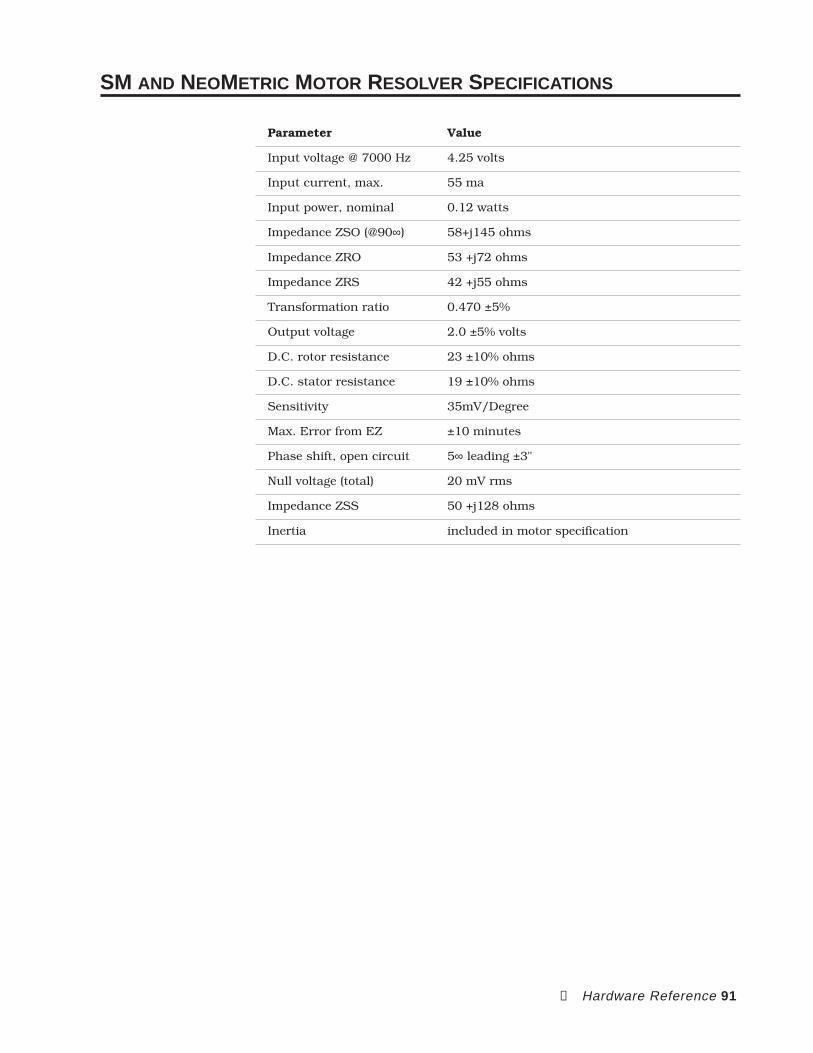
➃ Hardware Reference 91
SM AND NEOMETRIC MOTOR RESOLVER SPECIFICATIONS
Parameter Value
Input voltage @ 7000 Hz 4.25 volts
Input current, max. 55 ma
Input power, nominal 0.12 watts
Impedance ZSO (@90∞) 58+j145 ohms
Impedance ZRO 53 +j72 ohms
Impedance ZRS 42 +j55 ohms
Transformation ratio 0.470 ±5%
Output voltage 2.0 ±5% volts
D.C. rotor resistance 23 ±10% ohms
D.C. stator resistance 19 ±10% ohms
Sensitivity 35mV/Degree
Max. Error from EZ ±10 minutes
Phase shift, open circuit 5∞ leading ±3"
Null voltage (total) 20 mV rms
Impedance ZSS 50 +j128 ohms
Inertia included in motor specification

92 APEX User Guide
SM231, SM232 & SM233 Motor Dimensions
Ø0.4331 +-0.0030.001
(11.001 +-0.007)0.002)
2.75(69.85) Sq.
Shaft Options
0.409 (10.4)Ø0.43 (11)
- N (None) - F (Flat)
- K (Sq. Key)
0.492(12.49)
0.197(5)
0.500(12.7) 0.158
(4.01)
0.530(13.46)
Motor Length
3.26(82.8)
Ø2.3622 +-0.00050.0003
(60 +-0.012)0.007)
Motor Sizes
ModelMotor Length
N0704 w/brake10.00 (254.00)
N0703 w/brake 9.00 (228.60)
N0702 w/brake8.00 (203.20)
N0701 w/brake7.00 (177.80)
2.05(52.1)
Brake Option -B MS Connectors-MS
Cable-10, -25
Flying Leads-FL
Feedback ConnMS 14 - 18
0.910 (23.1)0.093 (2.36)
Motor ConnMS 14 - 12
4 x Ø0.228 (5.8) Thru HolesEq Spaced on a Ø 2.953 (75.00)Bolt Circle for 5mm or #10 Bolt
N07047.94 (201.68)N07036.94 (176.28)N07025.94 (150.88)N07014.94 (125.48)
NeoMetric 70mm Motor Dimensions
2.25 (57.15) Sq.1.856 (47.142) Sq.
2.99(75.95)
Cable OptionFlying Leads
MS Connectors
Motor Length
0.75 (19.05)0.81 (20.57)
(4x) Ø 0.218 (5.537)thru holes equally spacedon Ø2.625 (66.675) bolt circle
Cable Options Motor SizesPart #
- FL
- 10
Description
18" Flying Leads
10 ft. Cable
233 Motor5.98 (151.89)
232 Motor4.98 (126.49)
231 Motor3.98 (101.09)
ModelMotor Length
Longer lengths availableConsult Compumotor for information
Ø0.3750 +-0.00000.0005
(9.525 +-0.0000)0.0127)
Ø1.500(38.1
0.0010.025)
+-+-
- F(Flat)
Shaft Options
Ø0.375(9.525)
- N(None)
- K(Sq Key)
0.094(23.88)
0.416(10.566)
- L(1.25 (31.75) Lg.)
1.25 (31.75)
1.19 (30.23)
0.340(8.636)
0.60(15.24)
DIMENSIONS — SM231, SM232, SM233
DIMENSIONS — NEOMETRIC 70MM
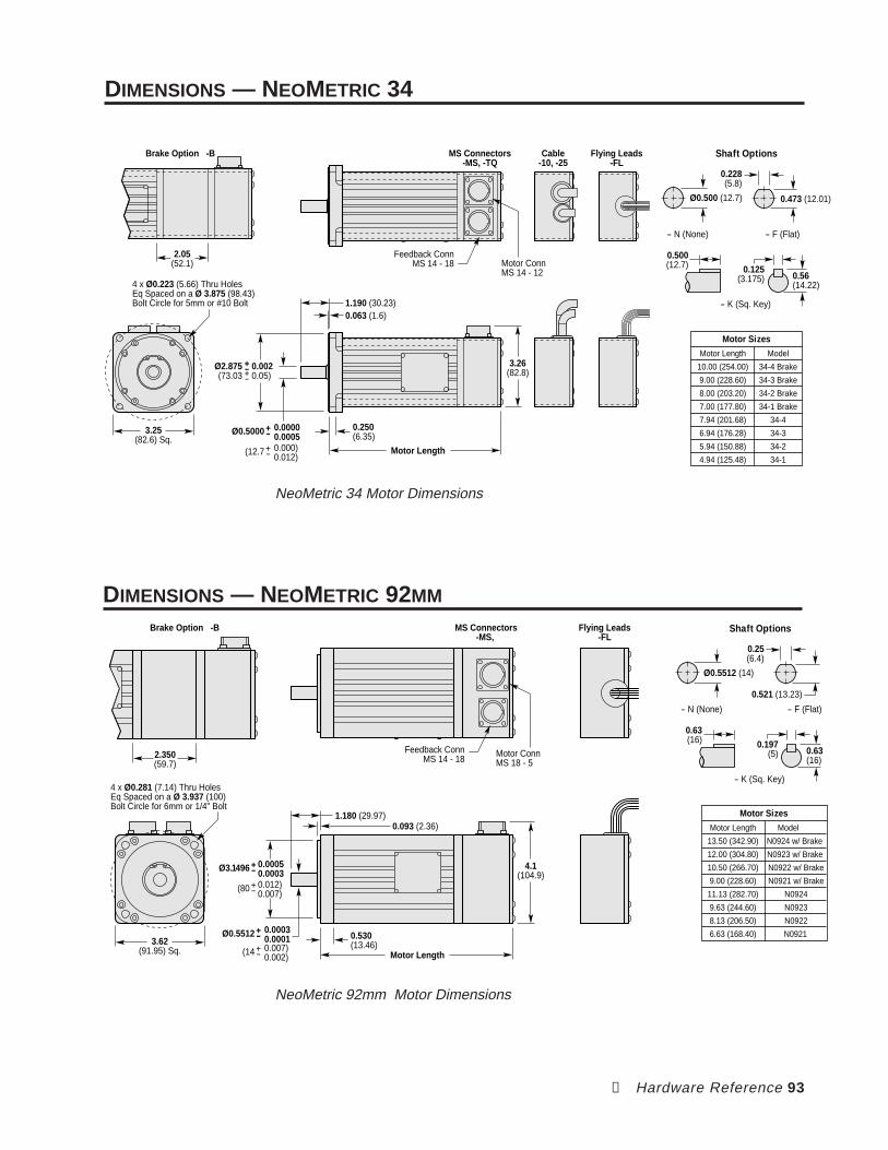
➃ Hardware Reference 93
Shaft Options
0.473 (12.01)Ø0.500 (12.7)
- N (None) - F (Flat)
- K (Sq. Key)
0.56(14.22)
0.228(5.8)
0.500(12.7) 0.125
(3.175)
Ø0.5000 +-0.00000.0005
(12.7 +-0.000)0.012)
0.250(6.35)
Motor Length
3.26(82.8)
Motor Sizes
34-4 Brake10.00 (254.00)
34-3 Brake9.00 (228.60)
ModelMotor Length
34-2 Brake8.00 (203.20)
34-1 Brake7.00 (177.80)
34-47.94 (201.68)
34-36.94 (176.28)
34-25.94 (150.88)
34-14.94 (125.48)
2.05(52.1)
Brake Option -B MS Connectors-MS, -TQ
Cable-10, -25
Flying Leads-FL
Feedback ConnMS 14 - 18 Motor Conn
MS 14 - 124 x Ø0.223 (5.66) Thru HolesEq Spaced on a Ø 3.875 (98.43)Bolt Circle for 5mm or #10 Bolt
3.25(82.6) Sq.
1.190 (30.23)0.063 (1.6)
Ø2.875(73.03
0.0020.05)
+-+-
NeoMetric 34 Motor Dimensions
NeoMetric 92mm Motor Dimensions
Shaft Options
Ø0.5512 (14)
- N (None) - F (Flat)
- K (Sq. Key)
0.63(16)
0.25(6.4)
0.63(16) 0.197
(5)
0.521 (13.23)
Motor Sizes
N0924 w/ Brake13.50 (342.90)
N0923 w/ Brake 12.00 (304.80)
ModelMotor Length
N0922 w/ Brake10.50 (266.70)
N0921 w/ Brake9.00 (228.60)
N092411.13 (282.70)
N09239.63 (244.60)
N09228.13 (206.50)
N0921 6.63 (168.40)
2.350(59.7)
Brake Option -B MS Connectors-MS,
Flying Leads-FL
Motor ConnMS 18 - 5
3.62(91.95) Sq.
4 x Ø0.281 (7.14) Thru HolesEq Spaced on a Ø 3.937 (100)Bolt Circle for 6mm or 1/4" Bolt
Feedback ConnMS 14 - 18
4.1(104.9)
0.530(13.46)
Motor Length
1.180 (29.97)0.093 (2.36)
Ø0.5512 +-0.00030.0001
(14 +-0.007)0.002)
Ø3.1496 +-0.00050.0003
(80 +-0.012)0.007)
DIMENSIONS — NEOMETRIC 34
DIMENSIONS — NEOMETRIC 92MM

94 APEX User Guide
This page left blank intentionally.

➄ Troubleshooting 95
5Troubleshooting
IN THIS CHAPTER
The information in this chapter will enable you to isolate andresolve system hardware problems.
C H A P T E R FIVE

96 APEX User Guide
TROUBLESHOOTING PROCEDURE
When your system does not function properly (or as you expect it tooperate), the first thing that you must do is identify and isolate the prob-lem. When you have accomplished this, you can effectively begin toresolve the problem.
The first step is to isolate each system component and ensure that eachcomponent functions properly when it is run independently. You mayhave to dismantle your system and put it back together piece by piece todetect the problem. If you have additional units available, you may wantto exchange them with existing components in your system to help iden-tify the source of the problem.
Determine if the problem is mechanical, electrical, or software-related.Can you repeat or recreate the problem? Do not attempt to make quickrationalizations about problems. Random events may appear to be re-lated, but they are not necessarily contributing factors to your problem.You must carefully investigate and decipher the events that occur beforethe subsequent system problem.
You may be experiencing more than one problem. You must isolate andsolve one problem at a time. Log (document) all testing and problemisolation procedures. You may need to review and consult these noteslater. This will also prevent you from duplicating your testing efforts.
If you are having difficulty isolating a problem be sure to document alloccurrences of the problem along with as much specific information, suchas time of occurrence, APEX status, and anything else that was happen-ing when the problem occurred.
Once you have isolated a problem, take the necessary steps to resolve it.Refer to the problem solutions contained in this chapter. If your system’sproblem persist, contact Parker Compumotor’s Applications Departmentat the phone number provided on the inside front cover of this document.

➄ Troubleshooting 97
DIAGNOSTIC LEDS
The APEX Drive has a bank of nine light emitting diodes (LEDs) on itsfront panel. Use these LEDs to isolate and identify problems.
The LED portion of the front panel is shown below. The Enable LED, whenilluminated, is green. All other LEDs are red when illuminated.
Tach Out Cal
EnableDisable
Bridge FaultDrive FaultMotor Fault
Over VoltageI2t Limit
Regen FaultRegen Active
ResetGnd
If a problem arises, first check the LEDs for an indication of the problem’sorigin. The next table explains situations that can illuminate each LED.Also see Recovering From Faults in the next section.
LED Description Latched (yes/no) How to reset the fault
Enable Indicates drive is enabled no n/a
Disable Indicates drive is disabled no see Note 1 and Note 2
Bridge Fault Power stage overtemperature yes Note 1Power stage overcurrent yes Note 1Motor short circuit yes Note 1
Drive Fault Control board overtemperature yes Note 1Undervoltage (brownout) yes Note 2
Motor Fault Resolver not connected yes Note 1Motor overtemperature yes Note 1Motor thermostat not connected yes Note 1
Over Voltage Fault Bus voltage exceeded 420VDC yes Note 1
I2T Limit I2T limit. Drive is in foldback. no Note 3Output is limited to continuouscurrent setting.
Regen Fault Excessive regeneration yes Note 1(external regeneration resistormay be required)
Regen Active Regeneration circuit active no Note 3(regeneration resistor is turnedon, and dissipating excess power)
Note 1: Activate Reset input on the controller connector (hold the inputat a low voltage—less than 1.0V—for at least 20 milliseconds; reset beginsupon release of the low voltage); or cycle power on Control L1/L2.
Note 2: When the bus voltage drops below 85VAC the Drive Fault LEDwill latch, indicating an undervoltage condition. When the bus voltage hasrecovered there are three ways to clear the drive fault: (1) issue a reset viathe RESET input, (2) cycle power on Control L1/L2 . (3) toggle the Enable Ininput.
Note 3: These conditions are not latched. Drive will recover on its ownwhen foldback or regen event is over.
98 APEX User Guide
RECOVERING FROM FAULTS
Fault conditions will shut down the APEX Drive’s current output to themotor. Before trying to restart your system, you should first solve theproblem that caused the fault. For example, if a short circuit in a motorcable caused a bridge fault, the same fault will probably occur when yourestart the drive—unless you first fix the problem.
Most of the fault conditions are latched. This means that after the prob-lem is fixed, the drive will not start up again on its own. You must firstreset the drive, or cycle power.
To reset the APEX Drive, send a reset signal to the APEX’s Reset input. Areset signal is a low voltage—less than 1.0V. You can ground the input, orhold it at a low voltage, for at least 20 milliseconds. Reset begins uponrelease of the low voltage.
To cycle power, turn off AC power to the APEX Drive, then turn the powerback on. If L1/L2(/L3) has a separate power input from Control L1/L2 , youcan cycle power by doing either of the following:
Turn off AC power only to Control L1/L2
Turn off AC power to both Control L1/L2 and L1/L2(/L3)
Turning off AC power only to L1/L2(/L3) will not clear all fault conditions.Even if you corrected the original fault, cycling power on L1/L2(/L3) willresult in a latched undervoltage fault. You would then need to cycle poweron Control L1/L2 to clear the undervoltage fault.
Recovery procedures for each fault condition are listed below.
BRIDGE FAULT
DRIVE FAULT
MOTOR FAULT
OVER VOLTAGE
REGEN FAULT
For each of these faults, the APEX Drive’s output current to the motor willbe latched off.
To recover from these fault conditions, do either of the following:
Reset the APEX Drive; or
Cycle Power
To recover from a Drive Fault caused by an undervoltage, you can useeither of the above methods; or, you can toggle the enable input after thevoltage has recovered.
I2T LIMITThis condition is not latched. It indicates that the APEX Drive is incurrent foldback, with its output current limited to the continuous cur-rent level. The drive may recover on its own, if the level of continuouscurrent is low enough to permit the motor to cool.
Under some conditions, the drive may not recover on its own—it may stayin current foldback. To recover, turn off AC power to the drive, then waitfor the motor to cool before you resume operations.

➄ Troubleshooting 99
Do not use the Reset input to clear the fault. If you do so, the protectivecircuit loses all information about motor temperature. It assumes themotor operates from a cold start, and it may not protect the motor fromoverheating if the motor is hot when you reset the drive.
When an I2T Limit occurs, it indicates that something is wrong with yoursystem—a mechanical jam, the motor is undersized, the move is tooaggressive for the motor, etc. You should solve the problem that causedthe I2T Limit .
The motor has less torque during an I2T Limit . If you configure yourcontroller to detect position errors, then an I2T Limit will probably cause aposition error fault in your controller.
REGEN ACTIVEThis is not a fault condition. When the LED turns on, it indicates that theinternal regeneration resistor is dissipating excess regenerated power. TheLED will turn off when the resistor stops dissipating power.
COMMUTATION TEST MODE
You can operate the APEX Drive in commutation test mode to help identifyand isolate problems. When it runs in commutation test mode, the APEXDrive does not use any motor feedback information for commutation. Itignores the resolver or the Hall effect sensor input, and commutates themotor in an open loop fashion at one revolution per second. The current itsends to the motor will be proportional to the command input voltage.
You can use commutation test mode to verify that your APEX Drive iscommutating properly, and that the motor phases are wired correctly.
To operate in commutation test mode:
➀ Turn off AC power to the APEX Drive.
➁ Turn DIP Switch#3, Position#3, ON.
➂ Turn on AC power to the APEX Drive.
➃ Slowly increase the command input voltage until the motor starts to turn.
➄ The APEX Drive should begin commutating the motor clockwise at thefollowing speeds:
• 1 rps (for 2-pole motors)
• 2/3 rps (for 3-pole motors)
➅ Depending upon your application, you may need to remove the load fromthe motor, or adjust command input to get adequate motor current. (Cur-rent will be scaled as set with DIP Switch#3, positions 6 & 7.)
100 APEX User Guide
RETURNING THE APEX DRIVE
If you must return your APEX system for repairs or upgrades, use thefollowing steps:
➀ Get the serial number and the model number of the defective unit, and apurchase order number to cover repair costs in the event the unit is deter-mined to be out of warranty.
➁ Before you return the unit, have someone from your organization with atechnical understanding of the APEX Drive and its application includeanswers to the following questions:
What is the extent of the failure/reason for return?
How long did it operate?
Did any other items fail at the same time?
What was happening when the unit failed (e.g., installing the unit,cycling power, starting other equipment, etc.)?
How was the product configured (in detail)?
What, if any, cables were modified and how?
With what equipment is the unit interfaced?
What was the application?
What was the system environment (temperature, enclosure,spacing, unit orientation, contaminants, etc.)?
What upgrades, if any, are required (hardware, cables, user guide)?
➂ In the USA, call your Automation Technology Center (ATC) for a ReturnMaterial Authorization (RMA) number. Returned products cannot be ac-cepted without an RMA number. If you cannot obtain an RMA number fromyour ATC, call Parker Compumotor’s Customer Service Department at (800)722-2282.
Ship the unit to: Parker Hannifin CorporationCompumotor Division5500 Business Park Drive, Suite DRohnert Park, CA 94928Attn: RMA # xxxxxxx
➃ In the UK, call Parker Digiplan for a GRA (Goods Returned Authorization)number. Returned products cannot be accepted without a GRA number.The phone number for Parker Digiplan Repair Department is 0202-690911.The phone number for Parker Digiplan Service/Applications Department is0202-699000.
Ship the unit to: Parker Digiplan Ltd.,21, Balena Close,Poole,Dorset,England.BH17 7DX
➄ Elsewhere: Contact the distributor who supplied the equipment.

Appendix A: APEX Motors 101
ΑAPEX Motors
IN THIS APPENDIX
Inspect the shipment
Recommended replacements
Configure DIP Switches
Mount the motor
Connect resolver and motor cables
Motor Specifications
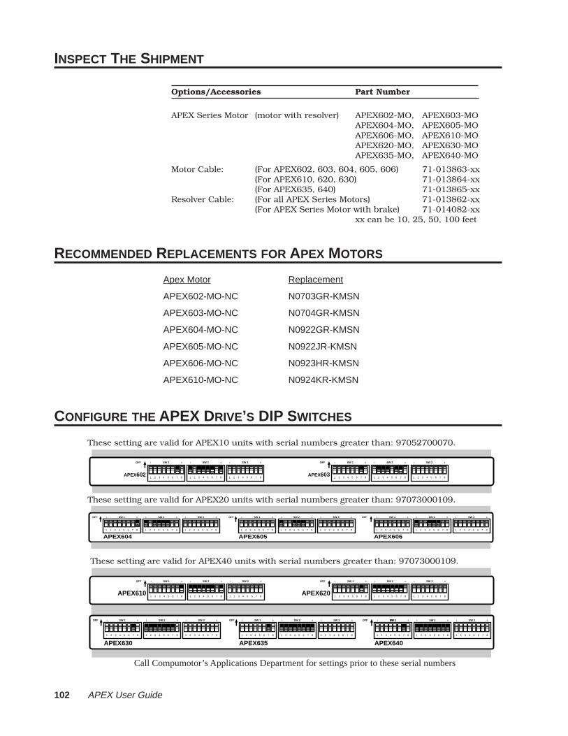
102 APEX User Guide
INSPECT THE SHIPMENT
Options/Accessories Part Number
APEX Series Motor (motor with resolver) APEX602-MO, APEX603-MOAPEX604-MO, APEX605-MOAPEX606-MO, APEX610-MOAPEX620-MO, APEX630-MOAPEX635-MO, APEX640-MO
Motor Cable: (For APEX602, 603, 604, 605, 606) 71-013863-xx(For APEX610, 620, 630) 71-013864-xx(For APEX635, 640) 71-013865-xx
Resolver Cable: (For all APEX Series Motors) 71-013862-xx(For APEX Series Motor with brake) 71-014082-xx
xx can be 10, 25, 50, 100 feet
RECOMMENDED REPLACEMENTS FOR APEX MOTORS
Apex Motor Replacement
APEX602-MO-NC N0703GR-KMSN
APEX603-MO-NC N0704GR-KMSN
APEX604-MO-NC N0922GR-KMSN
APEX605-MO-NC N0922JR-KMSN
APEX606-MO-NC N0923HR-KMSN
APEX610-MO-NC N0924KR-KMSN
CONFIGURE THE APEX DRIVE’S DIP SWITCHES
These setting are valid for APEX10 units with serial numbers greater than: 97052700070.
These setting are valid for APEX20 units with serial numbers greater than: 97073000109.
These setting are valid for APEX40 units with serial numbers greater than: 97073000109.
APEX604 APEX605 APEX6061 2 3 4 5 6 7 81 2 3 4 5 6 7 81 2 3 4 5 6 7 8
SW 11 8 SW 21 8 SW 31 8OFF
1 2 3 4 5 6 7 81 2 3 4 5 6 7 8
SW 11 8 SW 21 8
1 2 3 4 5 6 7 8
SW 31 8OFF
1 2 3 4 5 6 7 81 2 3 4 5 6 7 81 2 3 4 5 6 7 8
SW 11 8 SW 21 8 SW 31 8OFF
APEX602 APEX6031 2 3 4 5 6 7 81 2 3 4 5 6 7 81 2 3 4 5 6 7 8
SW 11 8 SW 21 8 SW 31 8OFF
1 2 3 4 5 6 7 81 2 3 4 5 6 7 81 2 3 4 5 6 7 8
SW 11 8 SW 21 8 SW 31 8OFF
APEX610 APEX620
APEX630 APEX635 APEX640
1 2 3 4 5 6 7 81 2 3 4 5 6 7 81 2 3 4 5 6 7 8
SW 11 8 SW 21 8 SW 31 8OFF
1 2 3 4 5 6 7 81 2 3 4 5 6 7 81 2 3 4 5 6 7 8
SW 11 8 SW 21 8 SW 31 8OFF
1 2 3 4 5 6 7 81 2 3 4 5 6 7 81 2 3 4 5 6 7 8
SW 11 8 SW 21 8 SW 31 8OFF
1 2 3 4 5 6 7 81 2 3 4 5 6 7 8
SW 11 8 SW 21 8
1 2 3 4 5 6 7 8
SW 31 8OFF
1 2 3 4 5 6 7 81 2 3 4 5 6 7 81 2 3 4 5 6 7 8
SW 11 8 SW 21 8 SW 31 8OFF SW 1
Call Compumotor’s Applications Department for settings prior to these serial numbers

Appendix A: APEX Motors 103
MOUNT THE MOTOR
MOTOR HEATSINKING
APEX (602 - 630 Motors) APEX (635 & 640 Motors)
8" x 12" x 0.25" 11.5" x 12" x 0.75"
(203 x 304 x 6.3 mm) (292 x 304 x 19 mm)
To get rated performance in your application, you must mount the motorto a heatsink of at least the same thermal capability as those listedabove. Mounting the motor to a smaller heatsink may result in decreasedperformance and a shorter service life. Conversely, mounting the motorto a larger heatsink can result in enhanced performance.
CONNECT THE RESOLVER CABLE
RESOLVER CONNECTIONS (COS, SIN, REF)Use the color code shown in the next drawing when you connect APEX orSM resolver cables. This code is also printed on the front panel of theAPEX Drive, near the resolver connector.
The Shield terminal is internally connected to Gnd (ground) terminals onthe front panel of the drive. If you make your own resolver cable, useshielded cable to keep electrical noise from corrupting the resolver signal.
Shield
Red
Black
Green
Blue
Brown
White
Motor Temp+
Motor Temp -
Fault Relay+
ShieldStator 3Stator 1Stator 2Stator 4Rotor 1Rotor 2Motor Temp+Motor Temp -
FunctionUninsulatedRedBlackGreenBlueBrownWhiteYellowOrange
APEX CableColor Code
Label onDrive
Ref
Sin
Cos
CONNECT THE MOTOR CABLE
MOTOR CONNECTIONS
Wire the cable to the motor connector. Use the following color code forAPEX motor cables.
Connector Terminal APEX Cable Wire ColorPhase A OrangePhase B BluePhase C GrayMotor Ground GreenShield Uninsulated
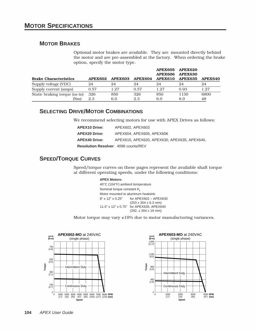
104 APEX User Guide
0
Torq
ue
Speed
APEX603-MO at 240VAC(single phase)
400(2.8)
800(5.6)
1,200(8.5)
1,600(11.3)
0 1000(17)
2000(33)
3000(50)
4000(67)
RPM(rps)
oz-in(N-m)
0
Torq
ue
Speed
APEX602-MO at 240VAC(single phase)
100(0.7)
300(2.1)
500(3.5)
700(4.9)
oz-in(N-m)
0 2000(33)
4000(67)
6000(100)
8000(133)
1000(17)
3000(50)
5000(83)
7000(117)
RPM(rps)
Intermittent Duty
Continuous Duty
Intermittent Duty
Continuous Duty
MOTOR SPECIFICATIONS
MOTOR BRAKES
Optional motor brakes are available. They are mounted directly behindthe motor and are pre-assembled at the factory. When ordering the brakeoption, specify the motor type.
APEX605 APEX620APEX606 APEX630
Brake Characteristics APEX602 APEX603 APEX604 APEX610 APEX635 APEX640Supply voltage (VDC) 24 24 24 24 24 24Supply current (amps) 0.57 1.27 0.57 1.27 0.93 1.27Static braking torque (oz-in) 326 850 326 850 1130 6800 (Nm) 2.3 6.0 2.3 6.0 8.0 48
SELECTING DRIVE/MOTOR COMBINATIONS
We recommend selecting motors for use with APEX Drives as follows:
APEX10 Drive: APEX602, APEX603
APEX20 Drive: APEX604, APEX605, APEX606
APEX40 Drive: APEX610, APEX620, APEX630, APEX635, APEX640,
Resolution Resolver : 4096 counts/REV
SPEED/TORQUE CURVES
Speed/torque curves on these pages represent the available shaft torqueat different operating speeds, under the following conditions:
APEX Motors:40°C (104°F) ambient temperatureNominal torque constant KtMotor mounted to aluminum heatsink:8" x 12" x 0.25" for APEX602 – APEX630
(203 x 304 x 6.3 mm)11.5" x 12" x 0.75" for APEX635, APEX640
(292. x 304 x 19 mm)
Motor torque may vary ±10% due to motor manufacturing variances.

Appendix A: APEX Motors 105
Speed
To
rqu
e
2000(33)
4000(67)
6000(100)
8000(133)
RPM(rps)
800
600
400
200
(5.6)
(4.2)
(2.8)
(1.4)
0
oz-in (N-m)
0
APEX604-MO at 240VAC
Intermittent Duty
Continuous Duty
240VAC*Single Phase
APEX605-MO at 240VAC
Speed
To
rqu
e
1200(20)
2400(40)
3600(60)
4800(80)
6000(100)
RPM(rps)
1200
900
600
300
(8.4)
(6.3)
(4.2)
(2.1)
0
oz-in (N-m)
0
Intermittent Duty
Continuous Duty
7200(120)
240VAC*Single Phase
APEX606-MO at 240VAC
Speed
To
rqu
e
1000(17)
2000(33)
3000(50)
4000(67)
RPM(rps)
2400
1800
1200
600
(16)
(12)
(8)
(4)
0
oz-in (N-m)
0
Intermittent Duty
Continuous Duty240VAC*Single Phase
APEX610-MO at 240VAC
Speed
To
rqu
e
2000(33)
4000(67)
6000(100)
8000(133)
RPM(rps)
2000
1500
1000
500
(14)
(10.6)
(7.0)
(3.5)
0
oz-in (N-m)
0
Intermittent Duty
Continuous Duty
240VAC**Single Phase
APEX620-MO at 240VAC
Speed
To
rqu
e
1000(17)
2000(33)
3000(50)
4000(67)
RPM(rps)
4000
3000
2000
1000
(28)
(21)
(14)
(7)
0
oz-in (N-m)
0
Intermittent Duty
Continuous Duty
240VAC**Single
APEX630-MO at 240VAC
Speed
To
rqu
e
600(10)
1200(20)
1800(30)
2400(40)
3000(50)
RPM(rps)
5600
4200
2800
1400
(39)
(29)
(19)
(9)
0
oz-in (N-m)
0
Intermittent Duty
Continuous Duty
3600(60)
240VAC**Single Phase
APEX635-MO at 240VAC
Speed
To
rqu
e
600(10)
1200(20)
1800(30)
2400(40)
3000(50)
RPM(rps)
5600
4200
2800
1400
(39)
(29)
(19)
(9)
0
oz-in (N-m)
0
Intermittent Duty
Continuous Duty
3600(60)
240VAC**Single
APEX640-MO at 240VAC
Speed
To
rqu
e
400(7)
800(13)
1200(20)
1600(27)
RPM(rps)
8000
6000
4000
2000
(56)
(42)
(28)
(14)
0
oz-in (N-m)
0
Intermittent Duty
Continuous Duty
2000(33)
240VAC**Single Phase
*240VAC single phase, 8A rms line current**240VAC single phase, 20A rms line current
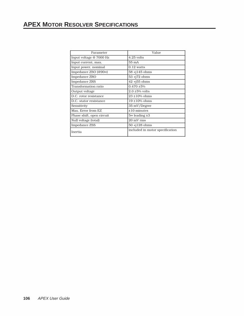
106 APEX User Guide
APEX MOTOR RESOLVER SPECIFICATIONS
retemaraP eulaV
zH0007@egatlovtupnI stlov52.4
.xam,tnerructupnI Am55
lanimon,rewoptupnI sttaw21.0
09@(OSZecnadepmI ∞) smho541j+85
ORZecnadepmI smho27j+35
SRZecnadepmI smho55j+24
oitarnoitamrofsnarT 074.0 ± %5
egatlovtuptuO 0.2 ± stlov%5
ecnatsiserrotor.C.D 32 ± smho%01
ecnatsiserrotats.C.D 91 ± smho%01
ytivitisneS eergeD/Vm53
ZEmorfrorrE.xaM ± setunim01
tiucricnepo,tfihsesahP 5∞ gnidael ±3
)latot(egatlovlluN smrVm02
SSZecnadepmI smho821j+05
aitrenInoitacificepsrotomnidedulcni
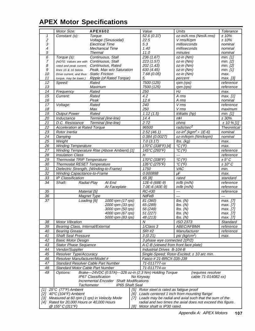
Appendix A: APEX Motors 107
APEX Motor SpecificationsMotor Size: APEX602 Value Units Tolerance
12345
Constant (s): TorqueVoltage (Sinusoidal)Electrical TimeMechanical TimeThermal
52.6 (0.37)22.55.31.4011.0
oz-in/A rms (Nm/A rms)V rms/Krpmmillisecondsmillisecondsminutes
± 10%± 10%nominalnominalnominal
6789
1011
Torque (s): Continuous, Stall(NOTE: Values are with Continuous, Stallrated and peak current, Continuous, Ratedlines 15 & 16 below. Peak, Max w/o SaturationDrive current, and thus Static Frictiontorque, may be lower.) Ripple (of Rated Torque)
236 (1.67)223 (1.57)202 (1.43)630 (4.45)7.68 (0.05)5
oz-in (Nm)oz-in (Nm)oz-in (Nm)oz-in (Nm)oz-in (Nm)percent
min. [1]min. [2]min. [2]min. [1]max.max. [3]
1213
Speed: RatedMaximum
7500 (125)7500 (125)
rpm (rps)rpm (rps)
referencereference
14 Frequency Rated 250 Hz max.1516
Current: RatedPeak
4.212.6
A rmsA rms
max. [1]nominal
1718
Voltage: RatedMax
240250
V rmsV rms
referencemaximum
19 Output Power Rated 1.12 (1.5) kWatts (hp) min. [1]20 Inductance Terminal (line-line) 14.4 mH ± 30%21 D.C. Resistance Terminal (line-line) 2.72 ohms ± 10 % [1]22 Acceleration at Rated Torque 96500 rads/sec2 Theoretical23 Rotor Inertia 2.52 (46.1) oz-in2 (kgm2 * 1E-6) nominal24 Damping 0.384 (0.0027) oz-in/krpm (Nm/krpm) nominal25 Weight 7.0 (3.17) lbs. (kg) max.26 Winding Temperature 170°C (338°F) [4] °C (°F) max.27 Winding Temperature Rise (Above Ambient) [1] 145°C (293°F) °C (°F) reference28 Insulation Class H — reference29 Thermostat TRIP Temperature 170°C (338°F) °C (°F) ± 5° C30 Thermostat RESET Temperature 135°C (275°F) °C (°F) ± 10° C31 Dielectric Strength, (Winding-to-Frame) 1750 VAC min.32 Winding Capacitance-to-Frame 0.000898 µF max.33 IP Classification 65 [8] rated standard34 Shaft: Radial-Play At End
At Faceplate12E-6 (68E-9)7.0E-6 (40E-9)
in/lb (m/N)in/lb (m/N)
referencereference
35 Material [5] RC-#30 — reference36 Magnet Type NdFeB — —37 Loading [6] 1000 rpm (17 rps)
2000 rpm (33 rps)3000 rpm (50 rps)4000 rpm (67 rps)5000 rpm (83 rps)
81 (360)65 (289)56 (249)51 (227)48 (213)
lbs. (N)lbs. (N)lbs. (N)lbs. (N)lbs. (N)
max. [7]max. [7]max. [7]max. [7]max. [7]
38 Motor Vibration N ISO 2373 Standard39 Bearing Class, Internal/External 1/Class 3 ABEC/AFBMA reference40 Bearing Grease SRI #2 Manufacturer reference41 Shaft Seal Pressure 3 (0.21) psi (kg/cm2) max.42 Basic Motor Design 3 phase wye connected 2(P/2)43 Stator Phase Sequence A-C-B (viewed from front face plate)44 Vendor/Supplier Industrial Drives B-104-B45 Resolver Type/Accuracy Single-Speed; Rotor-Excited; ± 10 arc min.46 Resolver Manufacturer/Model # Fasco # 21-BRCX-335-J3947 Standard Resolver Cable Part Number 71-011777-xx48 Standard Motor Cable Part Number 71-011774-xx49 Options: Brake—24VDC (0.57A)—326 oz-in (2.3 Nm) Holding Torque (requires resolver
IP67 Classification No Keyway cable 71-014082-xx)Incremental Encoder Shaft ModificationsTachometer IP65 Shaft Seal
[1] 25°C (77°F) Ambient[2] 40°C (104°F) Ambient[3] Measured at 60 rpm (1 rps) in Velocity Mode[4] Rated for 20,000 Hours or 40,000 Hours
@ 155° C (311°F)
[5] Rotor steel is rated as fatigue proof[6] Loads centered 1 inch from mounting flange[7] Loads may be radial and axial such that the sum of the
radial and two times the axial does not exceed this figure.[8] Motor shaft is IP30 rated.
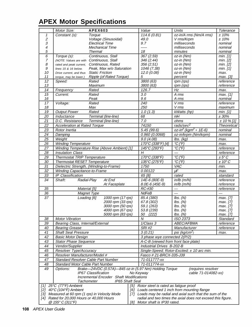
108 APEX User Guide
APEX Motor SpecificationsMotor Size: APEX603 Value Units Tolerance
12345
Constant (s): TorqueVoltage (Sinusoidal)Electrical TimeMechanical TimeThermal
114.6 (0.81)49.09.7-----18
oz-in/A rms (Nm/A rms)V rms/Krpmmillisecondsmillisecondsminutes
± 10%± 10%nominalnominalnominal
6789
1011
Torque (s): Continuous, Stall(NOTE: Values are with Continuous, Stallrated and peak current, Continuous, Ratedlines 15 & 16 below. Peak, Max w/o SaturationDrive current, and thus Static Frictiontorque, may be lower.) Ripple (of Rated Torque)
367 (2.59)346 (2.44)356 (2.51)1046 (7.38)12.0 (0.08)5
oz-in (Nm)oz-in (Nm)oz-in (Nm)oz-in (Nm)oz-in (Nm)percent
min. [1]min. [2]min. [2]min. [1]max.max. [3]
1213
Speed: RatedMaximum
3800 (63)3800 (63)
rpm (rps)rpm (rps)
referencereference
14 Frequency Rated 126.7 Hz max.1516
Current: RatedPeak
3.09.6
A rmsA rms
max. [1]nominal
1718
Voltage: RatedMax
240250
V rmsV rms
referencemaximum
19 Output Power Rated 1.0 (1.3) kWatts (hp) min. [1]20 Inductance Terminal (line-line) 68 mH ± 30%21 D.C. Resistance Terminal (line-line) 7.0 ohms ± 10 % [1]22 Acceleration at Rated Torque 74150 rads/sec2 Theoretical23 Rotor Inertia 5.45 (99.6) oz-in2 (kgm2 * 1E-6) nominal24 Damping 0.960 (0.0068) oz-in/krpm (Nm/krpm) nominal25 Weight 9.0 (4.08) lbs. (kg) max.26 Winding Temperature 170°C (338°F) [4] °C (°F) max.27 Winding Temperature Rise (Above Ambient) [1] 145°C (293°F) °C (°F) reference28 Insulation Class H — reference29 Thermostat TRIP Temperature 170°C (338°F) °C (°F) ± 5° C30 Thermostat RESET Temperature 135°C (275°F) °C (°F) ± 10° C31 Dielectric Strength, (Winding-to-Frame) 1750 VAC min.32 Winding Capacitance-to-Frame 0.00122 µF max.33 IP Classification 65 [8] rated standard34 Shaft: Radial-Play At End
At Faceplate14E-6 (80E-9)8.0E-6 (45E-9)
in/lb (m/N)in/lb (m/N)
referencereference
35 Material [5] RC-#30 — reference36 Magnet Type NdFeB — —37 Loading [6] 1000 rpm (17 rps)
2000 rpm (33 rps)3000 rpm (50 rps)4000 rpm (67 rps)5000 rpm (83 rps)
85.4 (380)67.8 (302)59.1 (263)53.8 (239)50 (222)
lbs. (N)lbs. (N)lbs. (N)lbs. (N)lbs. (N)
max. [7]max. [7]max. [7]max. [7]max. [7]
38 Motor Vibration N ISO 2373 Standard39 Bearing Class, Internal/External 1/Class 3 ABEC/AFBMA reference40 Bearing Grease SRI #2 Manufacturer reference41 Shaft Seal Pressure 3 (0.21) psi (kg/cm2) max.42 Basic Motor Design 3 phase wye connected 2(P/2)43 Stator Phase Sequence A-C-B (viewed from front face plate)44 Vendor/Supplier Industrial Drives B-202-B45 Resolver Type/Accuracy Single-Speed; Rotor-Excited; ± 10 arc min.46 Resolver Manufacturer/Model # Fasco # 21-BRCX-335-J3947 Standard Resolver Cable Part Number 71-011777-xx48 Standard Motor Cable Part Number 71-011774-xx49 Options: Brake—24VDC (0.57A)—845 oz-in (5.97 Nm) Holding Torque (requires resolver
IP67 Classification No Keyway cable 71-014082-xx)Incremental Encoder Shaft ModificationsTachometer IP65 Shaft Seal
[1] 25°C (77°F) Ambient[2] 40°C (104°F) Ambient[3] Measured at 60 rpm (1 rps) in Velocity Mode[4] Rated for 20,000 Hours or 40,000 Hours
@ 155° C (311°F)
[5] Rotor steel is rated as fatigue proof[6] Loads centered 1 inch from mounting flange[7] Loads may be radial and axial such that the sum of the
radial and two times the axial does not exceed this figure.[8] Motor shaft is IP30 rated.

Appendix A: APEX Motors 109
APEX Motor SpecificationsMotor Size: APEX604 Value Units Tolerance
12345
Constant (s): TorqueVoltage (Sinusoidal)Electrical TimeMechanical TimeThermal
52.6 (0.37)22.558.71.3012
oz-in/A rms (Nm/A rms)V rms/Krpmmillisecondsmillisecondsminutes
± 10%± 10%nominalnominalnominal
6789
1011
Torque (s): Continuous, Stall(NOTE: Values are with Continuous, Stallrated and peak current, Continuous, Ratedlines 15 & 16 below. Peak, Max w/o SaturationDrive current, and thus Static Frictiontorque, may be lower.) Ripple (of Rated Torque)
334 (2.36)315 (2.22)269 (1.90)899 (6.35)9.6 (0.07)5
oz-in (Nm)oz-in (Nm)oz-in (Nm)oz-in (Nm)oz-in (Nm)percent
min. [1]min. [2]min. [2]min. [1]max.max. [3]
1213
Speed: RatedMaximum
7500 (125)7500 (125)
rpm (rps)rpm (rps)
referencereference
14 Frequency Rated 250 Hz max.1516
Current: RatedPeak
6.018.8
A rmsA rms
max. [1]nominal
1718
Voltage: RatedMax
240250
V rmsV rms
referencemaximum
19 Output Power Rated 1.5 (2.0) kWatts (hp) min. [1]20 Inductance Terminal (line-line) 9.4 mH ± 30%21 D.C. Resistance Terminal (line-line) 1.6 ohms ± 10 % [1]22 Acceleration at Rated Torque 82980 rads/sec2 Theoretical23 Rotor Inertia 4.18 (76.5) oz-in2 (kgm2 * 1E-6) nominal24 Damping 0.580 (0.0041) oz-in/krpm (Nm/krpm) nominal25 Weight 8.5 (3.86) lbs. (kg) max.26 Winding Temperature 170°C (338°F) [4] °C (°F) max.27 Winding Temperature Rise (Above Ambient) [1] 145°C (293°F) °C (°F) reference28 Insulation Class H — reference29 Thermostat TRIP Temperature 170°C (338°F) °C (°F) ± 5° C30 Thermostat RESET Temperature 135°C (275°F) °C (°F) ± 10° C31 Dielectric Strength, (Winding-to-Frame) 1750 VAC min.32 Winding Capacitance-to-Frame 0.00122 µF max.33 IP Classification 65 [8] rated standard34 Shaft: Radial-Play At End
At Faceplate12E-6 (68E-9)5.6E-6 (32E-9)
in/lb (m/N)in/lb (m/N)
referencereference
35 Material [5] RC-#30 — —36 Magnet Type NdFeB — —37 Loading [6] 1000 rpm (17 rps)
2000 rpm (33 rps)3000 rpm (50 rps)4000 rpm (67 rps)5000 rpm (83 rps)
84 (374)67 (298)58 (258)53 (236)49 (218)
lbs. (N)lbs. (N)lbs. (N)lbs. (N)lbs. (N)
max. [7]max. [7]max. [7]max. [7]max. [7]
38 Bearing Class, Internal/External 1/Class 3 ABEC/AFBMA reference39 Bearing Grease SRI #2 Manufacturer reference40 Shaft Seal Pressure 3 (0.21) psi (kg/cm2) max.41 Basic Motor Design 3 phase wye connected 2(P/2)42 Stator Phase Sequence A-C-B (viewed from front face plate)43 Vendor/Supplier Industrial Drives B-106-B44 Resolver Type/Accuracy Single-Speed; Rotor-Excited; ± 10 arc min.45 Resolver Manufacturer/Model # Fasco # 21-BRCX-335-J3946 Standard Resolver Cable Part Number 71-013862-xx47 Standard Motor Cable Part Number 71-013863-xx48 Options: Brake—24VDC (0.57A)—326 oz-in (2.3 Nm) Holding Torque
IP67 ClassificationIncremental EncoderTachometerNo Keyway
[1] 25°C (77°F) Ambient[2] 40°C (104°F) Ambient[3] Measured at 60 rpm (1 rps) in Velocity Mode[4] Rated for 20,000 Hours or 40,000 Hours
@ 155° C (311°F)
[5] Rotor steel is rated as fatigue proof[6] Loads centered 1 inch from mounting flange[7] Loads may be radial and axial such that the sum of the
radial and two times the axial does not exceed this figure.[8] Motor shaft is IP30 rated.

110 APEX User Guide
APEX Motor SpecificationsMotor Size: APEX605 Value Units Tolerance
12345
Constant (s): TorqueVoltage (Sinusoidal)Electrical TimeMechanical TimeThermal
68.7 (0.49)29.410.681.4618
oz-in/A rms (Nm/A rms)V rms/Krpmmillisecondsmillisecondsminutes
± 10%± 10%nominalnominalnominal
6789
1011
Torque (s): Continuous, Stall(NOTE: Values are with Continuous, Stallrated and peak current, Continuous, Ratedlines 15 & 16 below. Peak, Max w/o SaturationDrive current, and thus Static Frictiontorque, may be lower.) Ripple (of Rated Torque)
367 (2.59)346 (2.44)321 (2.27)1085 (7.66)0.96 (0.007)5
oz-in (Nm)oz-in (Nm)oz-in (Nm)oz-in (Nm)oz-in (Nm)percent
min. [1]min. [2]min. [2]min. [1]max.max. [3]
1213
Speed: RatedMaximum
6200 (103)6200 (103)
rpm (rps)rpm (rps)
referencereference
14 Frequency Rated 207 Hz max.1516
Current: RatedPeak
516.6
A rmsA rms
max. [1]nominal
1718
Voltage: RatedMax
240250
V rmsV rms
referencemaximum
19 Output Power Rated 1.5 (2.0) kWatts (hp) min. [1]20 Inductance Terminal (line-line) 25 mH ± 30%21 D.C. Resistance Terminal (line-line) 2.3 ohms ± 10 % [1]22 Acceleration at Rated Torque 76870 rads/sec2 Theoretical23 Rotor Inertia 5.43 (99.6) oz-in2 (kgm2 * 1E-6) nominal24 Damping 0.96 (0.0068) oz-in/krpm (Nm/krpm) nominal25 Weight 10 (4.5) lbs. (kg) max.26 Winding Temperature 170°C (338°F) [4] °C (°F) max.27 Winding Temperature Rise (Above Ambient) [1] 145°C (293°F) °C (°F) reference28 Insulation Class H — reference29 Thermostat TRIP Temperature 170°C (338°F) °C (°F) ± 5° C30 Thermostat RESET Temperature 135°C (275°F) °C (°F) ± 10° C31 Dielectric Strength, (Winding-to-Frame) 1750 VAC min.32 Winding Capacitance-to-Frame 0.00122 µF max.33 IP Classification 65 [8] rated standard34 Shaft: Radial-Play At End
At Faceplate14E-6 (80E-9)8E-6 (45E-9)
in/lb (m/N)in/lb (m/N)
eferencereference
35 Material [5] RC-#30 — —36 Magnet Type NdFeB — —37 Loading [6] 1000 rpm (17 rps)
2000 rpm (33 rps)3000 rpm (50 rps)4000 rpm (67 rps)5000 rpm (83 rps)
85.4 (380)67.8 (301)59.1 (263)53.8 (239)50 (222)
lbs. (N)lbs. (N)lbs. (N)lbs. (N)lbs. (N)
max. [7]max. [7]max. [7]max. [7]max. [7]
38 Bearing Class, Internal/External 1/Class 3 ABEC/AFBMA reference39 Bearing Grease SRI #2 Manufacturer reference40 Shaft Seal Pressure 3 (0.21) psi (kg/cm2) max.41 Basic Motor Design 3 phase wye connected 2(P/2)42 Stator Phase Sequence A-C-B (viewed from front face plate)43 Vendor/Supplier Industrial Drives B-202-C44 Resolver Type/Accuracy Single-Speed; Rotor-Excited; ± 10 arc min.45 Resolver Manufacturer/Model # Fasco # 21-BRCX-335-J3946 Standard Resolver Cable Part Number 71-013862-xx47 Standard Motor Cable Part Number 71-013863-xx48 Options: Brake—24VDC (0.57A)—850 oz-in (6.0 Nm) Holding Torque
IP67 ClassificationIncremental EncoderTachometerNo Keyway
[1] 25°C (77°F) Ambient[2] 40°C (104°F) Ambient[3] Measured at 60 rpm (1 rps) in Velocity Mode[4] Rated for 20,000 Hours or 40,000 Hours
@ 155° C (311°F)
[5] Rotor steel is rated as fatigue proof[6] Loads centered 1 inch from mounting flange[7] Loads may be radial and axial such that the sum of the
radial and two times the axial does not exceed this figure.[8] Motor shaft is IP30 rated.
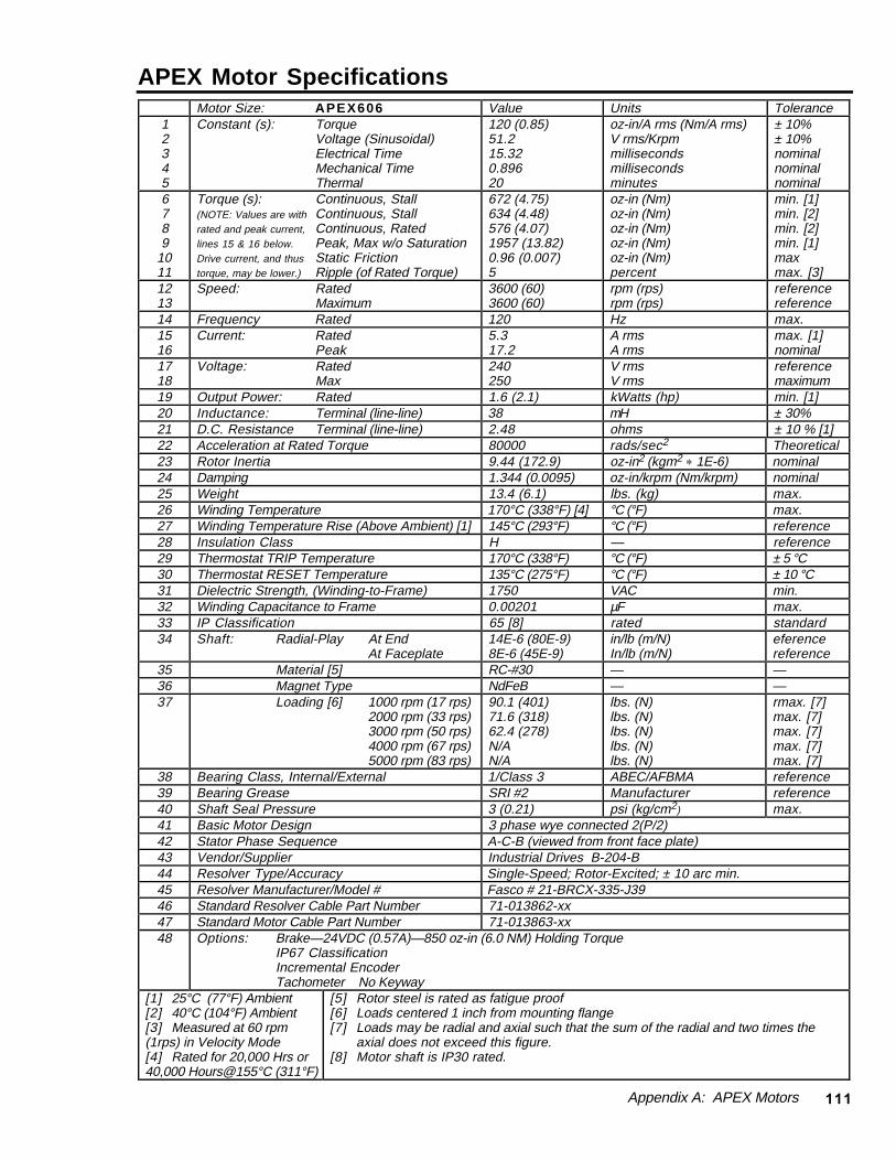
Appendix A: APEX Motors 111
APEX Motor SpecificationsMotor Size: APEX606 Value Units Tolerance
12345
Constant (s): TorqueVoltage (Sinusoidal)Electrical TimeMechanical TimeThermal
120 (0.85)51.215.320.89620
oz-in/A rms (Nm/A rms)V rms/Krpmmillisecondsmillisecondsminutes
± 10%± 10%nominalnominalnominal
6789
1011
Torque (s): Continuous, Stall(NOTE: Values are with Continuous, Stallrated and peak current, Continuous, Ratedlines 15 & 16 below. Peak, Max w/o SaturationDrive current, and thus Static Frictiontorque, may be lower.) Ripple (of Rated Torque)
672 (4.75)634 (4.48)576 (4.07)1957 (13.82)0.96 (0.007)5
oz-in (Nm)oz-in (Nm)oz-in (Nm)oz-in (Nm)oz-in (Nm)percent
min. [1]min. [2]min. [2]min. [1]maxmax. [3]
1213
Speed: RatedMaximum
3600 (60)3600 (60)
rpm (rps)rpm (rps)
referencereference
14 Frequency Rated 120 Hz max.1516
Current: RatedPeak
5.317.2
A rmsA rms
max. [1]nominal
1718
Voltage: RatedMax
240250
V rmsV rms
referencemaximum
19 Output Power: Rated 1.6 (2.1) kWatts (hp) min. [1]20 Inductance: Terminal (line-line) 38 mH ± 30%21 D.C. Resistance Terminal (line-line) 2.48 ohms ± 10 % [1]22 Acceleration at Rated Torque 80000 rads/sec2 Theoretical23 Rotor Inertia 9.44 (172.9) oz-in2 (kgm2 * 1E-6) nominal24 Damping 1.344 (0.0095) oz-in/krpm (Nm/krpm) nominal25 Weight 13.4 (6.1) lbs. (kg) max.26 Winding Temperature 170°C (338°F) [4] °C (°F) max.27 Winding Temperature Rise (Above Ambient) [1] 145°C (293°F) °C (°F) reference28 Insulation Class H — reference29 Thermostat TRIP Temperature 170°C (338°F) °C (°F) ± 5 °C30 Thermostat RESET Temperature 135°C (275°F) °C (°F) ± 10 °C31 Dielectric Strength, (Winding-to-Frame) 1750 VAC min.32 Winding Capacitance to Frame 0.00201 µF max.33 IP Classification 65 [8] rated standard34 Shaft: Radial-Play At End
At Faceplate14E-6 (80E-9)8E-6 (45E-9)
in/lb (m/N)In/lb (m/N)
eferencereference
35 Material [5] RC-#30 — —36 Magnet Type NdFeB — —37 Loading [6] 1000 rpm (17 rps)
2000 rpm (33 rps)3000 rpm (50 rps)4000 rpm (67 rps)5000 rpm (83 rps)
90.1 (401)71.6 (318)62.4 (278)N/AN/A
lbs. (N)lbs. (N)lbs. (N)lbs. (N)lbs. (N)
rmax. [7]max. [7]max. [7]max. [7]max. [7]
38 Bearing Class, Internal/External 1/Class 3 ABEC/AFBMA reference39 Bearing Grease SRI #2 Manufacturer reference40 Shaft Seal Pressure 3 (0.21) psi (kg/cm2) max.41 Basic Motor Design 3 phase wye connected 2(P/2)42 Stator Phase Sequence A-C-B (viewed from front face plate)43 Vendor/Supplier Industrial Drives B-204-B44 Resolver Type/Accuracy Single-Speed; Rotor-Excited; ± 10 arc min.45 Resolver Manufacturer/Model # Fasco # 21-BRCX-335-J3946 Standard Resolver Cable Part Number 71-013862-xx47 Standard Motor Cable Part Number 71-013863-xx48 Options: Brake—24VDC (0.57A)—850 oz-in (6.0 NM) Holding Torque
IP67 ClassificationIncremental EncoderTachometer No Keyway
[1] 25°C (77°F) Ambient[2] 40°C (104°F) Ambient[3] Measured at 60 rpm(1rps) in Velocity Mode[4] Rated for 20,000 Hrs or40,000 Hours@155°C (311°F)
[5] Rotor steel is rated as fatigue proof[6] Loads centered 1 inch from mounting flange[7] Loads may be radial and axial such that the sum of the radial and two times the
axial does not exceed this figure.[8] Motor shaft is IP30 rated.

112 APEX User Guide
APEX Motor SpecificationsMotor Size: APEX610 Value Units Tolerance
12345
Constant (s): TorqueVoltage (Sinusoidal)Electrical TimeMechanical TimeThermal
61.4 (0.43)26.213.160.76221
oz-in/A rms (Nm/A rms)V rms/Krpmmillisecondsmillisecondsminutes
± 10%±10%nominalnominalnominal
6789
1011
Torque (s): Continuous, Stall(NOTE: Values are with Continuous, Stallrated and peak current, Continuous, Ratedlines 15 & 16 below. Peak, Max w/o SaturationDrive current, and thus Static Frictiontorque, may be lower.) Ripple (of Rated Torque)
977 (6.90)921.6 (6.51)653 (4.61)2630 (18.57)0.96 (0.007)5
oz-in (Nm)oz-in (Nm)oz-in (Nm)oz-in (Nm)oz-in (Nm)percent
min. [1]min. [2]min. [2]min. [1]maxmin. [3]
1213
Speed: RatedMaximum
7000 (117)7000 (117)
rpm (rps)rpm (rps)
referencereference
14 Frequency Rated 233 Hz max.1516
Current: RatedPeak
1545
A rmsA rms
max. [1]nominal
1718
Voltage: RatedMax
230250
V rmsV rms
referencemaximum
19 Output Power: Rated 3.3 (4.5) kWatts (hp) min. [1]20 Inductance: Terminal (line-line) 5 mH ± 30%21 D.C. Resistance Terminal (line-line) 0.38 ohms ± 10 % [1]22 Acceleration at Rated Torque 73934 rads/sec2 Theoretical23 Rotor Inertia 13.72 (251.2) oz-in2 (kgm2 * 1E-6) nominal24 Damping 1.728 (0.0122) oz-in/krpm (Nm/krpm) nominal25 Weight 16.35 (7.43) lbs. (kg) max.26 Winding Temperature 170°C (338°F) [4] °C (°F) max.27 Winding Temperature Rise (Above Ambient) [1] 145°C (293°F) °C (°F) reference28 Insulation Class H — reference29 Thermostat TRIP Temperature 170°C (338°F) °C (°F) ± 5 °C30 Thermostat RESET Temperature 135°C (275°F) °C (°F) ± 10 °C31 Dielectric Strength, (Winding-to-Frame) 1750 VAC min.32 Winding Capacitance-to-Frame 0.00205 µF max.33 IP Classification 65 [8] rated standard34 Shaft: Radial-Play At End
At Faceplate14E-6 (80E-9)8E-6 (45E-9)
in/lb (m/N)in/lb (m/N)
referencereference
35 Material [5] RC-#3036 Magnet Type NdFeB37 Loading [6] 1000 rpm (17 rps)
2000 rpm (33 rps)3000 rpm (50 rps)4000 rpm (67 rps)5000 rpm (83 rps)
93.5 (416)74.2 (330)64.8 (288)59 (262)54.7 (243)
lbs. (N)lbs. (N)lbs. (N)lbs. (N)lbs. (N)
max. [7]max. [7]max. [7]max. [7]max. [7]
38 Bearing Class, Internal/External 1/Class 3 ABEC/AFBMA reference39 Bearing Grease SRI #2 Manufacturer reference40 Shaft Seal Pressure 3 (0.21) psi (kg/cm2) max.41 Basic Motor Design 3 phase wye connected 2(P/2)42 Stator Phase Sequence A-C-B (viewed from front face plate)43 Vendor/Supplier Industrial Drives B-206-D44 Resolver Type/Accuracy Single-Speed; Rotor-Excited; ± 10 arc min.45 Resolver Manufacturer/Model # Fasco # 21-BRCX-335-J3946 Standard Resolver Cable Part Number 71-013862-xx47 Standard Motor Cable Part Number 71-013864-xx48 Options: Brake—24VDC (0.57A)—850 oz-in (6.0 Nm) Holding Torque
IP67 ClassificationIncremental EncoderTachometerNo Keyway
[1] 25°C (77°F) Ambient[2] 40°C (104°F) Ambient[3] Measured at 60 rpm (1 rps) in Velocity Mode[4] Rated for 20,000 Hours or 40,000 Hours
@ 155° C (311°F)
[5] Rotor steel is rated as fatigue proof[6] Loads centered 1 inch from mounting flange[7] Loads may be radial and axial such that the sum of the
radial and two times the axial does not exceed this figure.[8] Motor shaft is IP30 rated.
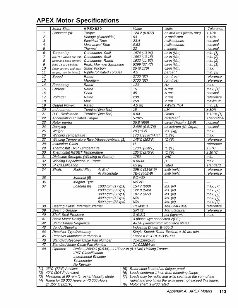
Appendix A: APEX Motors 113
APEX Motor SpecificationsMotor Size: APEX620 Value Units Tolerance
12345
Constant (s): TorqueVoltage (Sinusoidal)Electrical TimeMechanical TimeThermal
124.2 (0.877)5323.40.8222
oz-in/A rms (Nm/A rms)V rms/Krpmmillisecondsmillisecondsminutes
± 10%± 10%nominalnominalnominal
6789
1011
Torque (s): Continuous, Stall(NOTE: Values are with Continuous, Stallrated and peak current, Continuous, Ratedlines 15 & 16 below. Peak, Max w/o SaturationDrive current, and thus Static Frictiontorque, may be lower.) Ripple (of Rated Torque)
1974 (13.94)1862 (13.15)1632 (11.52)5299 (37.42)25 (0.176)4.5
oz-in (Nm)oz-in (Nm)oz-in (Nm)oz-in (Nm)oz-in (Nm)percent
min. [1]min. [2]min. [2]min. [1]max.min. [3]
1213
Speed: RatedMaximum
3700 (62)3700 (62)
rpm (rps)rpm (rps)
referencereference
14 Frequency Rated 123 Hz max.1516
Current: RatedPeak
1545
A rmsA rms
max. [1]nominal
1718
Voltage: RatedMax
230250
V rmsV rms
referencemaximum
19 Output Power: Rated 4.5 (6) kWatts (hp) min. [1]20 Inductance: Terminal (line-line) 15 mH ± 30%21 D.C. Resistance Terminal (line-line) 0.64 Ohms ± 10 % [1]22 Acceleration at Rated Torque 57025 rads/sec2 Theoretical23 Rotor Inertia 35.8 (656) oz-in2 (kgm2 * 1E-6) nominal24 Damping 2.496 (0.0176) oz-in/krpm (Nm/krpm) nominal25 Weight 29 (13.2) lbs. (kg) max.26 Winding Temperature 170°C (338°F) [4] °C (°F) max.27 Winding Temperature Rise (Above Ambient) [1] 145°C (293°F) °C (°F) reference28 Insulation Class H — reference29 Thermostat TRIP Temperature 170°C (338°F) °C (°F) ± 5 °C30 Thermostat RESET Temperature 135°C (275°F) °C (°F) ± 10 °C31 Dielectric Strength, (Winding-to-Frame) 1750 VAC min.32 Winding Capacitance-to-Frame 0.0034 µF max.33 IP Classification 65 [8] rated standard34 Shaft: Radial-Play At End
At Faceplate20E-6 (114E-9)7E-6 (40E-9)
in/lb (m/N)in/lb (m/N)
referencereference
35 Material [5] RC-#30 — —36 Magnet Type NdFeB — —37 Loading [6] 1000 rpm (17 rps)
2000 rpm (33 rps)3000 rpm (50 rps)4000 rpm (67 rps)5000 rpm (83 rps)
154.7 (688)122.8 (546)107.2 (477)N/AN/A
lbs. (N)lbs. (N)lbs. (N)lbs. (N)lbs. (N)
max. [7]max. [7]max. [7]max. [7]max. [7]
38 Bearing Class, Internal/External 1/Class 3 ABEC/AFBMA reference39 Bearing Grease SRI #2 Manufacturer reference40 Shaft Seal Pressure 3 (0.21) psi (kg/cm2) max.41 Basic Motor Design 3 phase wye connected 2(P/2)42 Stator Phase Sequence A-C-B (viewed from front face plate)43 Vendor/Supplier Industrial Drives B-404-D44 Resolver Type/Accuracy Single-Speed; Rotor-Excited; ± 10 arc min.45 Resolver Manufacturer/Model # Fasco # 21-BRCX-335-J3946 Standard Resolver Cable Part Number 71-013862-xx47 Standard Motor Cable Part Number 71-013864-xx48 Options: Brake—24VDC (0.93A)—1130 oz-in (8.0 Nm) Holding Torque
IP67 ClassificationIncremental EncoderTachometerNo Keyway
[1] 25°C (77°F) Ambient[2] 40°C (104°F) Ambient[3] Measured at 60 rpm (1 rps) in Velocity Mode[4] Rated for 20,000 Hours or 40,000 Hours
@ 155° C (311°F)
[5] Rotor steel is rated as fatigue proof[6] Loads centered 1 inch from mounting flange[7] Loads may be radial and axial such that the sum of the
radial and two times the axial does not exceed this figure.[8] Motor shaft is IP30 rated.
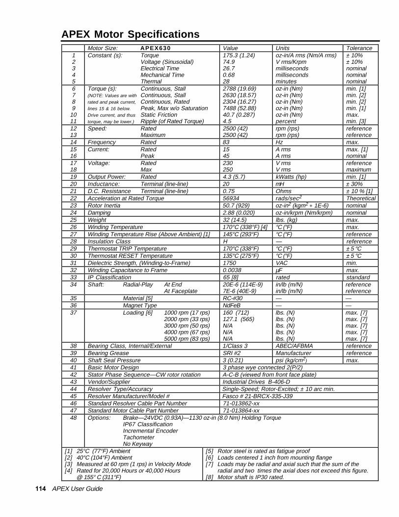
114 APEX User Guide
APEX Motor SpecificationsMotor Size: APEX630 Value Units Tolerance
12345
Constant (s): TorqueVoltage (Sinusoidal)Electrical TimeMechanical TimeThermal
175.3 (1.24)74.926.70.6828
oz-in/A rms (Nm/A rms)V rms/Krpmmillisecondsmillisecondsminutes
± 10%± 10%nominalnominalnominal
6789
1011
Torque (s): Continuous, Stall(NOTE: Values are with Continuous, Stallrated and peak current, Continuous, Ratedlines 15 & 16 below. Peak, Max w/o SaturationDrive current, and thus Static Frictiontorque, may be lower.) Ripple (of Rated Torque)
2788 (19.69)2630 (18.57)2304 (16.27)7488 (52.88)40.7 (0.287)4.5
oz-in (Nm)oz-in (Nm)oz-in (Nm)oz-in (Nm)oz-in (Nm)percent
min. [1]min. [2]min. [2]min. [1]max.min. [3]
1213
Speed: RatedMaximum
2500 (42)2500 (42)
rpm (rps)rpm (rps)
referencereference
14 Frequency Rated 83 Hz max.1516
Current: RatedPeak
1545
A rmsA rms
max. [1]nominal
1718
Voltage: RatedMax
230250
V rmsV rms
referencemaximum
19 Output Power: Rated 4.3 (5.7) kWatts (hp) min. [1]20 Inductance: Terminal (line-line) 20 mH ± 30%21 D.C. Resistance Terminal (line-line) 0.75 Ohms ± 10 % [1]22 Acceleration at Rated Torque 56934 rads/sec2 Theoretical23 Rotor Inertia 50.7 (929) oz-in2 (kgm2 * 1E-6) nominal24 Damping 2.88 (0.020) oz-in/krpm (Nm/krpm) nominal25 Weight 32 (14.5) lbs. (kg) max.26 Winding Temperature 170°C (338°F) [4] °C (°F) max.27 Winding Temperature Rise (Above Ambient) [1] 145°C (293°F) °C (°F) reference28 Insulation Class H — reference29 Thermostat TRIP Temperature 170°C (338°F) °C (°F) ± 5 °C30 Thermostat RESET Temperature 135°C (275°F) °C (°F) ± 5 °C31 Dielectric Strength, (Winding-to-Frame) 1750 VAC min.32 Winding Capacitance to Frame 0.0038 µF max.33 IP Classification 65 [8] rated standard34 Shaft: Radial-Play At End
At Faceplate20E-6 (114E-9)7E-6 (40E-9)
in/lb (m/N)in/lb (m/N)
referencereference
35 Material [5] RC-#30 — —36 Magnet Type NdFeB — —37 Loading [6] 1000 rpm (17 rps)
2000 rpm (33 rps)3000 rpm (50 rps)4000 rpm (67 rps)5000 rpm (83 rps)
160 (712)127.1 (565)N/AN/AN/A
lbs. (N)lbs. (N)lbs. (N)lbs. (N)lbs. (N)
max. [7]max. [7]max. [7]max. [7]max. [7]
38 Bearing Class, Internal/External 1/Class 3 ABEC/AFBMA reference39 Bearing Grease SRI #2 Manufacturer reference40 Shaft Seal Pressure 3 (0.21) psi (kg/cm2) max.41 Basic Motor Design 3 phase wye connected 2(P/2)42 Stator Phase Sequence—CW rotor rotation A-C-B (viewed from front face plate)43 Vendor/Supplier Industrial Drives B-406-D44 Resolver Type/Accuracy Single-Speed; Rotor-Excited; ± 10 arc min.45 Resolver Manufacturer/Model # Fasco # 21-BRCX-335-J3946 Standard Resolver Cable Part Number 71-013862-xx47 Standard Motor Cable Part Number 71-013864-xx48 Options: Brake—24VDC (0.93A)—1130 oz-in (8.0 Nm) Holding Torque
IP67 ClassificationIncremental EncoderTachometerNo Keyway
[1] 25°C (77°F) Ambient[2] 40°C (104°F) Ambient[3] Measured at 60 rpm (1 rps) in Velocity Mode[4] Rated for 20,000 Hours or 40,000 Hours
@ 155° C (311°F)
[5] Rotor steel is rated as fatigue proof[6] Loads centered 1 inch from mounting flange[7] Loads may be radial and axial such that the sum of the
radial and two times the axial does not exceed this figure.[8] Motor shaft is IP30 rated.

Appendix A: APEX Motors 115
APEX Motor SpecificationsMotor Size: APEX635 Value Units Tolerance
12345
Constant (s): TorqueVoltage (Sinusoidal)Electrical TimeMechanical TimeThermal
164.0 (1.154)700.7720.828
oz-in/A rms (Nm/A rms)V rms/Krpmmillisecondsmillisecondsminutes
± 10%± 10%nominalnominalnominal
6789
1011
Torque (s): Continuous, Stall(NOTE: Values are with Continuous, Stallrated and peak current, Continuous, Ratedlines 15 & 16 below. Peak, Max w/o SaturationDrive current, and thus Static Frictiontorque, may be lower.) Ripple (of Rated Torque)
2605 (18.39)2458 (17.36)2054 (14.50)7008 (49.49)69 (0.49)4.5
oz-in (Nm)oz-in (Nm)oz-in (Nm)oz-in (Nm)oz-in (Nm)percent
min. [1]min. [2]min. [2]min. [1]max.min. [3]
1213
Speed: RatedMaximum
3000 (50)3000 (50)
rpm (rps)rpm (rps)
referencereference
14 Frequency Rated 150 Hz max.1516
Current: RatedPeak
1545
A rmsA rms
max. [1]nominal
1718
Voltage: RatedMax
230250
V rmsV rms
referencemaximum
19 Output Power: Rated 4.5 (6.1) kWatts (hp) min. [1]20 Inductance: Terminal (line-line) 14 mH ± 30%21 D.C. Resistance Terminal (line-line) 0.647 Ohms ± 10 % [1]22 Acceleration at Rated Torque 48945 rads/sec2 Theoretical23 Rotor Inertia 56.1 (1028) oz-in2 (kgm2 * 1E-6) nominal24 Damping 2.88 (0.020) oz-in/krpm (Nm/krpm) nominal25 Weight 37 (16.8) lbs. (kg) max.26 Winding Temperature 170°C (338°F) [4] °C (°F) max.27 Winding Temperature Rise (Above Ambient) [1] 145°C (293°F) °C (°F) reference28 Insulation Class H — reference29 Thermostat TRIP Temperature 170°C (338°F) °C (°F) ± 5 °C30 Thermostat RESET Temperature 135°C (275°F) °C (°F) ± 5 °C31 Dielectric Strength, (Winding-to-Frame) 1750 VAC min.32 Winding Capacitance to Frame 0.0038 µF max.33 IP Classification 65 rated standard34 Shaft: Radial-Play At End
At Faceplate20E-6 (114E-9)7E-6 (40E-9)
in/lb (m/N)in/lb (m/N)
referencereference
35 Material [5] RC-#3036 Magnet Type NdFeB 37 Loading [6] 1000 rpm (17 rps)
2000 rpm (33 rps)3000 rpm (50 rps)4000 rpm (67 rps)5000 rpm (83 rps)
243.5 (1,083)193.3 (860)168.8 (751)N/AN/A
lbs. (N)lbs. (N)lbs. (N)lbs. (N)lbs. (N)
max. [7]max. [7]max. [7]max. [7]max. [7]
38 Bearing Class, Internal/External 1/Class 3 ABEC/AFBMA reference39 Bearing Grease SRI #2 Manufacturer reference40 Shaft Seal Pressure 3 (0.21) psi (kg/cm2) max.41 Basic Motor Design 3 phase wye connected 3(P/2)42 Stator Phase Sequence—CW rotor rotation A-C-B (viewed from front face plate)43 Vendor/Supplier Industrial Drives B-602-C44 Resolver Type/Accuracy Single-Speed; Rotor-Excited; ± 10 arc min.45 Resolver Manufacturer/Model # Fasco # 21-BRCX-335-J3946 Standard Resolver Cable Part Number 71-013862-xx47 Standard Motor Cable Part Number 71-013865-xx48 Options: Brake—24VDC (0.93A)— 1130 oz-in(8.0 Nm) Holding Torque
IP67 ClassificationIncremental EncoderTachometerNo Keyway
[1] 25°C (77°F) Ambient[2] 40°C (104°F) Ambient[3] Measured at 60 rpm (1 rps) in Velocity Mode[4] Rated for 20,000 Hours or 40,000 Hours
@ 155° C (311°F)
[5] Rotor steel is rated as fatigue proof[6] Loads centered 1 inch from mounting flange[7] Loads may be radial and axial such that the sum of the
radial and two times the axial does not exceed this figure.[8] Motor shaft is IP30 rated.

116 APEX User Guide
APEX Motor SpecificationsMotor Size: APEX640 Value Units Tolerance
12345
Constant (s): TorqueVoltage (Sinusoidal)Electrical TimeMechanical TimeThermal
291.5 (2.06)124.526.20.5533
oz-in/A rms (Nm/A rms)V rms/Krpmmillisecondsmillisecondsminutes
± 10%± 10%nominalnominalnominal
6789
1011
Torque (s): Continuous, Stall(NOTE: Values are with Continuous, Stallrated and peak current, Continuous, Ratedlines 15 & 16 below. Peak, Max w/o SaturationDrive current, and thus Static Frictiontorque, may be lower.) Ripple (of Rated Torque)
4640 (32.76)4378 (30.92)3955 (27.93)12461 (87.99)73 (0.52)4.5
oz-in (Nm)oz-in (Nm)oz-in (Nm)oz-in (Nm)oz-in (Nm)percent
min. [1]min. [2]min. [2]min. [1]max.max. [3]
1213
Speed: RatedMaximum
1600 (27)1600 (27)
rpm (rps)rpm (rps)
referencereference
14 Frequency Rated 80 Hz max.1516
Current: RatedPeak
1545
A rmsA rms
max. [1]nominal
1718
Voltage: RatedMax
230250
V rmsV rms
reference maximum
19 Output Power: Rated 4.7 (6.3) kWatts (hp) min. [1]20 Inductance: Terminal (line-line) 20 mH ± 30%21 D.C. Resistance Terminal (line-line) 0.763 Ohms ± 10 % [1]22 Acceleration at Rated Torque 43667 rads/sec2 Theoretical23 Rotor Inertia 111.0 (2034) oz-in2 (kgm2 * 1E-6) nominal24 Damping 15.36 (0.1085) oz-in/krpm (Nm/krpm) nominal25 Weight 51 (23.2) lbs. (kg) max.26 Winding Temperature 170°C (338°F) [4] °C (°F) max.27 Winding Temperature Rise (Above Ambient) [1] 145°C (293°F) °C (°F) reference28 Insulation Class H — reference29 Thermostat TRIP Temperature 170°C (338°F) °C (°F) ± 5 °C30 Thermostat RESET Temperature 135°C (275°F) °C (°F) ± 10 °C31 Dielectric Strength, (Winding-to-Frame) 1750 VAC min.32 Winding Capacitance to Frame 0.0082 µF max.33 IP Classification 65 [8] rated standard34 Shaft: Radial-Play At End
At Faceplate10E-6 (57E-9)4E-6 (23E-9)
in/lb (m/N)in/lb (m/N)
referencereference
35 Material [5] RC-#30 — —36 Magnet Type NdFeB — —37 Loading [6] 1000 rpm (17 rps)
2000 rpm (33 rps)3000 rpm (50 rps)4000 rpm (67 rps)5000 rpm (83 rps)
255.6 (1,130)N/AN/AN/AN/A
lbs. (N)lbs. (N)lbs. (N)lbs. (N)lbs. (N)
max. [7]max. [7]max. [7]max. [7]max. [7]
38 Bearing Class, Internal/External 1/Class 3 ABEC/AFBMA reference39 Bearing Grease SRI #2 Manufacturer reference40 Shaft Seal Pressure 3 (0.21) psi (kg/cm2) max.41 Basic Motor Design 3 phase wye connected 3(P/2)42 Stator Phase Sequence—CW rotor rotation A-C-B (viewed from front face plate)43 Vendor/Supplier Industrial Drives B-604-D44 Resolver Type/Accuracy Single-Speed; Rotor-Excited; ± 10 arc min.45 Resolver Manufacturer/Model # Fasco # 21-BRCX-335-J3946 Standard Resolver Cable Part Number 71-013862-xx47 Standard Motor Cable Part Number 71-013865-xx48 Options: Brake—24VDC (1.27A)—6800 oz-in (48 Nm) Holding Torque
IP67 ClassificationIncremental EncoderTachometer No Keyway
[1] 25°C (77°F) Ambient[2] 40°C (104°F) Ambient[3] Measured at 60 rpm (1 rps) in Velocity Mode[4] Rated for 20,000 Hours or 40,000 Hours
@ 155° C (311°F)
[5] Rotor steel is rated as fatigue proof[6] Loads centered 1 inch from mounting flange[7] Loads may be radial and axial such that the sum of the
radial and two times the axial does not exceed this figure.[8] Motor shaft is IP30 rated.
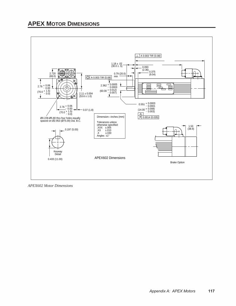
Appendix A: APEX Motors 117
APEX MOTOR DIMENSIONS
2.720(69.0)
2.11 ± 0.004(53.6 ± 1.0)
0.07 (1.8)
1.18 ± .02(30.0 ± .5) 0.093
(2.36)0.375(9.54)
1.53(38.9)
Brake Option
Dimension—inches (mm)
Tolerances unless otherwise specified: .XXX ±.005 .XX ±.010 .X ±.030 Angles ±1°
2.76
(70.0
+-+-
0.060.001.5)0.0)
2.76
(70.0
+-+-
0.060.001.5)0.0)
Ø0.228-Ø5.80 thru four holes equallyspaced on Ø2.953 (Ø75.00) Dia. B.C.
0.197 (5.00)
0.433 (11.00)
KeywayDetail
0.551 +-
0.00030.0001
(14.00 +-
0.008)0.003)
-A-0.0014 (0.035)
0.79 (20.0)minA 0.003 TIR (0.08)
2.362 +-
0.00050.0003
(60.00 +-
0.012)0.007)
A 0.003 TIR (0.08)
APEX602 Dimensions
APEX602 Motor Dimensions
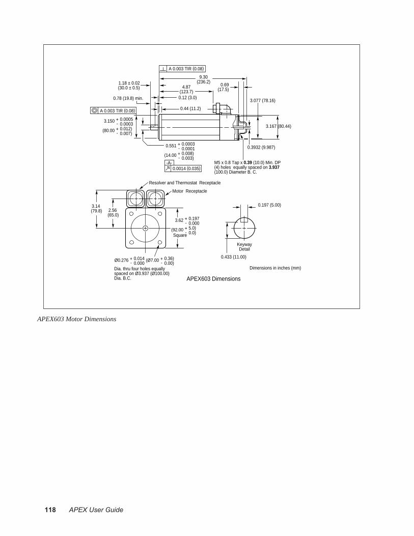
118 APEX User Guide
9.30(236.2)
4.87(123.7)
3.14 (79.8) 2.56
(65.0)
Dimensions in inches (mm)
APEX603 Dimensions
1.18 ± 0.02(30.0 ± 0.5)
0.12 (3.0)
0.44 (11.2)
0.78 (19.8) min.
A 0.003 TIR (0.08)
A 0.003 TIR (0.08)
0.3932 (9.987)
3.077 (78.16)
3.167 (80.44)
M5 x 0.8 Tap x 0.39 (10.0) Min. DP(4) holes equally spaced on 3.937(100.0) Diameter B. C.
0.69(17.5)
Motor Receptacle
3.62
(92.00
+-+-
0.1970.0005.0)0.0)Square
Ø0.276 +-
0.0140.000
(Ø7.00 +-
0.36)0.00)
Dia. thru four holes equallyspaced on Ø3.937 (Ø100.00)Dia. B.C.
Resolver and Thermostat Receptacle
3.150 +-
0.00050.0003
(80.00 +-
0.012)0.007)
0.551 +-
0.00030.0001
(14.00 +-
0.008)0.003)
0.197 (5.00)
0.433 (11.00)
KeywayDetail
-A-0.0014 (0.035)
APEX603 Motor Dimensions
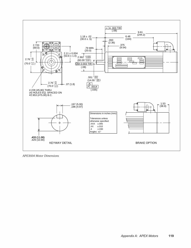
Appendix A: APEX Motors 119
2.720(69.0)
2.11 ± 0.004(53.6 ± 1.0)
2.76 +.06-.00
(70.0 +1.5-0.0 )
2.76 +.06-.00
(70.0 +1.5-0.0 )
.07 (1.8)
ø.228 (ø5.80) THRU(4) HOLES EQ. SPACED ONø2.953 (ø75.00) B.C.
1.18 ± .02(30.0 ± .5)
.551 +.0003-.0001
(14.00 +.008-.003 )
6.48(164).093
(2.36).375(9.54).79 MIN
(20.0)
9.61(244.2)
-A-.0014
A 0.003 TIR
A .003 TIR(.08)
(.035)
(.08)
2.362 +0.0005-0.0003
(60.00 )+0.012-0.007
.433 (11.00)
.429 (10.90)
.197 (5.00)
.196 (4.97)
KEYWAY DETAIL
.433 (11.00)
1.53(38.9)
BRAKE OPTION
Dimensions in inches (mm)
Tolerances unless otherwise specified: .XXX ±.005 .XX ±.010 .X ±.030 Angles ±1°
APEX604 Motor Dimensions
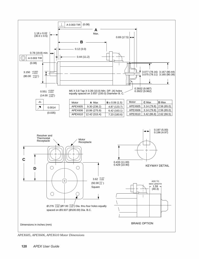
120 APEX User Guide
1.18 ± 0.02(30.0 ± 0.5)
0.12 (3.0)
0.44 (11.2)
0.78 (19.8) min.
A 0.003 TIR
A 0.003 TIR
(0.08)
0.3932 (9.987)0.3922 (9.962)
A
B
Max.
3.077 (78.16)3.075 (78.11)
3.167 (80.44)3.165 (80.39)
3.150
(80.00 )
+0.0005-0.0003
+0.012-0.007
M5 X 0.8 Tap X 0.39 (10.0) Min. DP. (4) holes equally spaced on 3.937 (100.0) Diameter B. C.
0.551
(14.00 )
+0.0003-0.0001
+0.008-0.003
0.0014
-A-
0.69 (17.5)
(0.035)
Ø.276 (Ø7.00 ) Dia. thru four holes equally
spaced on Ø3.937 (Ø100.00) Dia. B.C.
Resolver andThermostat Receptacle Motor
Receptacle
3.62
(92.00 )
Square
+0.197-0.000
+0.014-0.000
+0.36-0.00
0.197 (5.00)0.196 (4.97)
0.433 (11.00)0.429 (10.90) KEYWAY DETAIL
Motor
APEX605
APEX606
APEX610
A Max
9.30 (236.2)
10.86 (275.8)
12.42 (315.4)
B ± 0.06 (1.5)
4.87 (123.7)
6.42 (163.1)
7.23 (183.6)
Dimensions in inches (mm)
(0.08)
+5.0-0.0
C Max
3.14 (79.8)
3.14 (79.8)
3.42 (86.8)
APEX605
APEX606
APEX610
D Max
2.56 (65.0)
2.56 (65.0)
2.62 (66.5)
Motor
C
D
BRAKE OPTION
ADD TOMAX LENGTH
1.59(40.3)
APEX605, APEX606, APEX610 Motor Dimensions
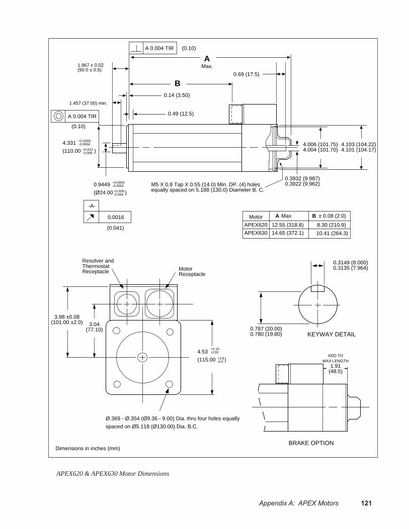
Appendix A: APEX Motors 121
0.9449
(Ø24.00 )
1.967 ± 0.02(50.0 ± 0.5)
0.14 (3.50)
0.49 (12.5)
1.457 (37.00) min.
A 0.004 TIR
A 0.004 TIR
(0.10)
0.3932 (9.987)0.3922 (9.962)
A
B
Max.
4.006 (101.75)4.004 (101.70)
4.103 (104.22)4.101 (104.17)
4.331
(110.00 )
+0.0005-0.0004
+0.013-0.009
M5 X 0.8 Tap X 0.55 (14.0) Min. DP. (4) holes equally spaced on 5.188 (130.0) Diameter B. C.
+0.0003-0.0002
0.0016
-A-
Ø.369 - Ø.354 (Ø9.36 - 9.00) Dia. thru four holes equally
spaced on Ø5.118 (Ø130.00) Dia. B.C.
Resolver andThermostat Receptacle Motor
Receptacle
3.98 ±0.08(101.00 ±2.0) 3.04
(77.10)
4.53
(115.00 )
+0.15-0.00
0.3149 (8.000)0.3135 (7.964)
0.787 (20.00)0.780 (19.80) KEYWAY DETAIL
Motor
APEX620
APEX630
A Max
12.55 (318.8)
14.65 (372.1)
B ± 0.08 (2.0)
8.30 (210.9)
10.41 (264.3)
Dimensions in inches (mm)
+3.8-0.0
0.69 (17.5)
+0.009-0.004
(0.10)
(0.041)
BRAKE OPTION
ADD TOMAX LENGTH
1.91(48.5)
APEX620 & APEX630 Motor Dimensions

122 APEX User Guide
0.9449
(Ø24.00 )
1.967 ± 0.02(50.0 ± 0.5)
0.14 (3.50)
0.71 (18.0)
1.457 (37.00) min.
A 0.004 TIR
A 0.004 TIR
(0.10)
0.3932 (9.987)0.3922 (9.962)
5.006 (127.15)5.004 (127.10)
5.103 (129.62)5.101 (129.57)
M5 X 0.8 Tap X 0.55 (14.0) Min. DP. (4) holes equally spaced on 6.457 (164.0) Diameter B. C.
+0.0003-0.0002
0.0016
-A-
Ø.433 (Ø11.00 ) Dia. thru four holes equally
spaced on Ø6.496 (Ø165.00) Dia. B.C.
Resolver andThermostat Receptacle Motor
Receptacle
5.23 ±0.08(132.9 ±2.0)
3.93(99.8)
5.59
(142.00 )
KEYWAY DETAIL
+3.3-0.0
0.69 (17.5)
+0.009-0.004
+0.13-0.00
(0.10)
(0.040)
+0.0006-0.0004
+0.014-0.011
5.118
(130.00 )
Motor
APEX635
APEX640
A Max11.78 (299.2)
14.48 (367.8)
B ± 0.08 (2.0)5.47 (139.0)
8.17 (207.6)
Dimensions in inches (mm)
B
AMax.
0.3149 (8.000)0.3135 (7.964)
0.787 (20.00)0.780 (19.80)
BRAKE OPTION
ADD TOMAX LENGTH
1.91(48.5)
APEX635 & APEX640 Motor Dimensions
Index 123
IndexSymbols
15V outputs 40, 756250 connections to APEX 39800 toll-free number. See inside cover
A
AC power connections 31air filter 21airborne contaminants 21airflow 23aligning resolver 19, 66ambient temperature 20APEX Drive
panel layout 24regeneration 56specifications 70
APEX Series motors. See motorapplications engineers. See inside cover
B
bandwidth 46bench test 11block diagrams 3brakes 54, 82, 104bridge fault 98
C
cable part numbers 8cable shield 30calculation method 60calibrate tachometer 42chassis ground 26circuit drawings 71circuit ground (Gnd) 26clearing faults 98collective gain adjustment 51collective gain DIP 20color code
motor cable 29, 103resolver cable 27, 103
command± input 74scaling with DIP switch 20
commutation test mode 19, 99component location 10connections 27
AC power cable 31controller 39encoder cable 41
Hall effect cable 78motor cable 29
connections to Compumotor 6250 39continuous current 18, 64Control L1/Control L2 33controller connector 39cos 27, 103couplers 43coupling manufacturers 44current foldback circuit 64current loop compensation 18custom regeneration resistor 63
D
description – APEX Drive 2diagnostic LEDs 97differential output 39dimensions
APEX Motors 117NeoMetric motors 92, 93SM Motors 92, 93
DIP switchlocation 11settings 11
DIP switch setting 18disconnecting AC power 34dissipation 24drive, APEX. See APEX drivedrive fault 98drive mounting 20dump (power dump) 56
E
earth ground 26electrical noise problems 21empirical method 59enable input 40, 73enclosure specifications 22encoder connector 76encoder features 41, 76encoder output 76environmental specifications 20
F
fault output 40, 74fault relay 28, 54, 80faults - recovering from 98feedback terminals 28, 80

124 APEX User Guide
front panel LEDs 97fusing information 31, 36
G
GND 26GRA (Goods Returned Authorization) number
100grounding
APEX ground system 26internal connections 40keyhole slot 21
H
Hall effectdegrees – DIP switch select 18DIP switch select 20input circuit schematic 77resolver connector jumpers 81
heatsinking 25, 103humidity 20
I
I/O pinouts 71I2T limit 64, 98input power 70integral gain 51internal temperature sensors 24isolated outputs 40, 75
L
L1/L2/L3 33LEDs 97light emitting diodes (LEDs) 97liquids 21location of components 10
M
maximum ambient temperature 20mechanical brake 54misalignment & couplers 43motor 28, 54
brakes 82, 104connections 71dimensions
NeoMetric 92, 93SM 92
fault 98ground 30heatsinking 25, 103motor temp± input 28, 79repeatability 82resolver accuracy 82specifications 82, 104speed/torque curves 83, 104
temperature 28, 79motor cable 29motor fault 98motor pole pair
DIP switch setting 18Motor Temp± input 28, 79mounting
drive 20motor 25, 103
O
offset balance adjustment 37output power 70overvoltage fault 58, 98
P
panel layout 24part numbers
APEX and SM motors 8cables 8connectors 8user guide 8
peak current 18, 64pinouts 71pole pairs 18power
input specifications 70output specifications 70
power connections 31power dump 56pseudo-quadrature outputs 76
Q
quadrature outputs 76quick test 11
R
recovering from faults 98ref 27, 103regen resistor
external 59, 62internal 56user supplied 63
regeneration 59regeneration fault 18, 57, 98regeneration specifications 62, 63relative humidity 20repeatability 82reset input 40, 72resistor braking 55resolver
accuracy 82alignment 19, 66cable 27

Index 125
connector 78resonance issues 45return procedure 100
S
schematics 71shield 26ship kit 8signal ground 40sin 27, 103single phase power 35, 36single speed resolver 18single-ended output 40SM Series Motors
specifications 89, 90SM Series motors. See motorSpecifications
SM Series motors 89, 90
T
tachometer calibration 42tachometer output 42, 75tachometer scaling
DIP switch setting 20temperature – maximum ambient 20temperature sensors 24test points 65test procedure
commutation 67torque mode 37velocity mode 38
time constant 64DIP switch setting 19
toll free number. See inside covertorque command 65torque mode test procedure 37torque/speed curves 83, 104transformer 32troubleshooting 96tuning 45
APEX motors 47multiple systems 52preliminary tuning 42SM Motors, tuning 46torque mode 47velocity mode 48
two-speed resolver 18
V
V Bus± 64velocity error 65velocity integral gain 51velocity integrator 19velocity integrator enable 73
velocity mode test procedure 38
W
weight of drives 71

126 APEX User Guide
This page left blank intentionally.
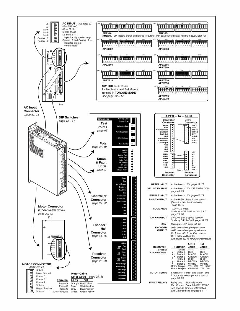
12
34
56
78
12
34
56
78
12
34
56
78
DA
NG
ER
L1
L2
Earth
Earth
Earth
Control L1
Control L2
HIG
H V
OLT
AG
E
OFF
18
SW
11
8S
W2
18
SW
3
Potspage 37, 49
TestPointspage 65
Status& Fault
LEDspage 97
Motor Connector(Underneath drive)page 29, 71
AC InputConnector page 31, 71
DIP Switchespage 12 – 17
ControllerConnectorpage 39, 72
Encoder/Hall
Connectorpage 41, 76
Resolver Connectorpage 27, 78
AC INPUT – see page 3185— 252 VAC47 — 66 HzSingle-phaseL1 and L2 — Input for high-power amp.Control L1 and Control L2 — Input for internal control logic
ENCODEROUTPUT
1024 counts/rev, pre-quadrature
Ch A leads Ch B, for CW rotation Ch Z pulse width is 90¡see pages 41, 76 for more information
4096 counts/rev, post-quadrature
RESET INPUT
ENABLE INPUT
FAULT OUTPUT
COMMAND±
±15V
VEL INT ENABLE
TACH OUTPUT
Active Low, <1.0V page 39, 72
Active Low, <1.0V page 40, 73
Active HIGH (floats if fault occurs)(Output is held low if no fault) page 40, 74
–10V = 16 ampsScale with DIP SW3 — pos. 6 & 7page 39, 74
MOTOR TEMP±
RESOLVER CABLE:
COLOR CODE
Short Motor Temp+ and Motor Temp- if motor has no temperature sensorpage 28, 79
FAULT RELAY± Relay type: Normally OpenMax Current: 5A at 24VDC/120VACsee page 80 for more informationsee Motor Braking on page 54
15 mA at –15V page 40, 75
Active Low, <1.0V (DIP SW3-#1 ON)page 48, 73
1V/1000 rpm; 1-speed resolver Scale by DIP SW3-#5 page 38, 75
ShieldStator 3Stator 1Stator 2Stator 4Rotor 1Rotor 2
Motor Temp+Motor Temp—
------REDBLACKGREENBLUEBROWNWHITEYELLOWORANGE
FunctionAPEXCable
------REDBLACKGREENBLUEBROWNWHITEYELLOWYELLOW
SMCable
Phase APhase BPhase C
Motor Ground
OrangeBlueGrayGreen
Motor CableColor Code
Terminal APEX
ResetGnd
Vel Int EnableEnable InFault Out
GndCommand+Command-
Tach OutputGnd
+15VGnd-15V
CHA+CHA–CHB+CHB–CHZ+CHZ–
Gnd
SHLDCOMSHTNCSHTNODFTAGNDANICMD-CMD+
Float
+5VA+A-B+B-Z+Z-GNDSHLDFloat
APEX – to – 6250ControllerConnector
DriveConnector
EncoderConnector
EncoderConnector
MOTOR CONNECTORpage 29, 71
Red/YellowWhite/YellowBlack/YellowGreen/Yellow
SMpage 29, 56
A P E X 1 0
Compumotor
Compumotor
Velocity Erro
r
Velocity Erro
r
Torque Cmd
Torque Cmd
Collectiv
e Gain
Collectiv
e Gain
Vel Integral G
ain
Vel Integral G
ain
Offset B
alance
Offset B
alance
Tach Out Cal
Tach Out Cal
Enable
Disable
Bridge Fault
Bridge Fault
Drive Fault
Drive Fault
Motor Fault
Motor Fault
Over Volta
ge
I2T Lim
it
Regen Fault
Regen Fault
Regen Active
Regen Active
Reset
Gnd
Vel Int E
nable
Vel Int E
nable
Enable In
Enable In
Fault Out
Fault Out
Gnd
Command+
Command -
Command -
Tach Output
Tach Output
Gnd
+15V
Gnd
-15V
CHA+
CHA -
CHB+
CHB -
CHZ+
CHZ -
Gnd
Shield
Red
Black
Green
Blue
Brown
White
Motor Temp+
Motor Temp+
Motor Temp -
Motor Temp -
Fault Relay+
Fault Relay+
Fault Relay -
Fault Relay -
Feedback+
Feedback -
Feedback -
DA
NG
ER
HIGH VOLTAGE
L1L2
Earth
Earth
Earth
Control L
1
Control L
2
Ref
Sin
Cos
ShieldMotor GroundPhase CPhase BPhase AV Bus -Regen ResistorV Bus+
Shield
Motor Ground
Phase C
Phase B
Phase A
V Bus -
Regen Resistor
V Bus+
D A N G E R
HIGH VOLTAGE
L1L2
EarthEarthEarth
Control L1Control L2
Compumotor Velocity Error
Torque Cmd
Collective Gain
Vel Integral Gain
Offset Balance
Tach Out Cal
Enable
Disable
Bridge Fault
Drive Fault
Motor Fault
Over Voltage
I2T Limit
Regen Fault
Regen Active
Reset
Gnd
Vel Int Enable
Enable In
Fault Out
Gnd
Command+
Command -
Tach Output
Gnd
+15V
Gnd
-15V
CHA+
CHA -
CHB+
CHB -
CHZ+
CHZ -
Gnd
Shield
Red
Black
Green
Blue
Brown
White
Motor Temp+
Motor Temp -
Fault Relay+
Fault Relay -
Feedback+
Feedback -
Ref
Sin
Cos
Ref
Sin
Cos
SWITCH SETTINGSfor NeoMetric and SM Motorsrunning in TORQUE MODEsee page 12 – 17
APEX602 APEX603
SM231ASM232A
SM233B
1 2 3 4 5 6 7 81 2 3 4 5 6 7 81 2 3 4 5 6 7 8
SW 11 8 SW 21 8 SW 31 8OFF
1 2 3 4 5 6 7 81 2 3 4 5 6 7 81 2 3 4 5 6 7 8
SW 11 8 SW 21 8 SW 31 8OFF
1 2 3 4 5 6 7 81 2 3 4 5 6 7 81 2 3 4 5 6 7 8
SW 11 8 SW 21 8 SW 31 8OFF
1 2 3 4 5 6 7 81 2 3 4 5 6 7 81 2 3 4 5 6 7 8
SW 11 8 SW 21 8 SW 31 8OFF
APEX604 APEX605APEX606
1 2 3 4 5 6 7 81 2 3 4 5 6 7 81 2 3 4 5 6 7 8
SW 11 8 SW 21 8 SW 31 8OFF
1 2 3 4 5 6 7 81 2 3 4 5 6 7 8
SW 11 8 SW 21 8
1 2 3 4 5 6 7 8
SW 31 8OFF
APEX610
APEX635APEX640
1 2 3 4 5 6 7 81 2 3 4 5 6 7 81 2 3 4 5 6 7 8
SW 11 8 SW 21 8 SW 31 8OFF
1 2 3 4 5 6 7 81 2 3 4 5 6 7 8
SW 11 8 SW 21 8
1 2 3 4 5 6 7 8
SW 31 8OFF
APEX620APEX630
1 2 3 4 5 6 7 81 2 3 4 5 6 7 81 2 3 4 5 6 7 8
SW 11 8 SW 21 8 SW 31 8OFF
SM Motors shown configured for tuning, with peak current set at minimum (6.5A) (pg 42)