ansys fluid dynamics update...multiphysics – 1-way fsi significantly faster surface mapping for...
TRANSCRIPT
© 2011 ANSYS, Inc. September 14, 2011
1
ANSYS Fluid Dynamics Update
André Bakker, Product Management
Madhusuden Agrawal, Technical Services

© 2011 ANSYS, Inc. September 14, 2011
2
ANSYS Fluid Dynamics
ANSYS Fluid Dynamics Products
• ANSYS Fluent
• ANSYS CFX
• ANSYS CFD-Post
• ANSYS TurboGrid
• ANSYS Polyflow
ANSYS Fluid Dynamics at 14.0
• Significant benefits for users
• Including geometry and meshing
• Look for detailed materials at release time

© 2011 ANSYS, Inc. September 14, 2011
3
Product Creation Teams (~600 Members)
Central
Development Unit
Brian Drew
•Framework, Tools
•Geometry/CAD
•Meshing
•Engineering
Knowledge
Manager
•Design Explorer
•Dev Services
•Funded
development
~30% dev. staff Technologist:
Chris Hawkins
Product Mgmt:
Scott Gilmore
Fluids
Systems
Nelson Carter
•FLUENT, CFX,
common platform
•Specialty CFD
•R&D initiatives
•Funded
development
~25% dev. staff
Mechanical
Systems
Joe Manich
•Mechanical
•Explicit
•Multibody dyn.
•R&D initiatives
•Funded
development
~25% dev. staff
Physics Business Unit
Joe Solecki
Technologists: Dave Conover,
Michael Engelman,
Dipankar Choudhury
Product Management: André Bakker
Electronics
Business Unit
Shane Emswiler
•High Frequency
•Low Frequency
•Electro-mechanical
•Signal Integrity
•RF/Electronics
•Funded development
•R&D initiatives
~ 20% dev. staff
Dev. Mgmt:
Nancy Lambert
Product Mgmt:
Larry Williams
Product Strategy & Planning, Partnerships, Corporate Product Management Josh Fredberg, S. Subbiah, and Todd McDevitt

© 2011 ANSYS, Inc. September 14, 2011
4
We are developing both Fluent and CFX:
• Both offer best-in-class solver technology, relied upon by leading industrial companies
• New feature releases are already being planned (R14.x and R15)
– Increased technology sharing between the two solvers
– Continued improvements in common Workbench based workflow
In addition, we remain committed to developing and releasing an
integrated, unified fluids product:
• That draws upon the best of both Fluent and CFX, as well as add new functionality
• That provides smooth adoption for our fluids customers
The first release of this product is targeted for ANSYS R15
Our Fluids Strategy

© 2011 ANSYS, Inc. September 14, 2011
5
• Rapid & Robust Meshing
• Workflow & Usability
• Multiphysics and Systems Coupling
• Solver and HPC Performance
• Rotating Machinery
• Automotive Power Train Modeling
• Multiphase Flow Modeling
• Comprehensive CFD Capabilities
• Special Material Processing
• Summary
Fluid Dynamics Themes

© 2011 ANSYS, Inc. September 14, 2011
6
Rapid & Robust Meshing
Top on the list of challenges
engineering companies are facing is
shortened product development
schedules while at the same time the
product designs themselves are
becoming increasingly complex.
Meshing of these designs introduce
challenges in terms of speed,
robustness and accuracy.
Courtesy Siemens AG.

© 2011 ANSYS, Inc. September 14, 2011
7
Rapid & Robust Meshing
Enhanced productivity through increased automation, flexibility, efficiency and robustness
• Assembly Meshing (Tet and CutCell)
• Performance (Speed, Robustness)
• Selective Meshing
• Virtual Topologies
• Hex Meshing
• ICEM CFD/Tgrid
• Solver meshing

© 2011 ANSYS, Inc. September 14, 2011
8
Assembly Meshing enables dramatically reduced time to mesh for typical CAD models by eliminating the tedious geometry clean-up
Top-down approach to mesh all parts at once
• Uses Virtual Bodies (material points or groups) to automatically extract internal regions from assemblies
• Supports:
– Meshing solids from sheet bodies
– Conformal mesh between parts without requiring multibody parts
– Overlapping bodies
– Tet (linear) and CutCell (hex-dominant) mesh types
– Inflation
Rapid & Robust Meshing – Assembly Meshing

© 2011 ANSYS, Inc. September 14, 2011
15
Productivity enhancements through increased robustness, flexibility, and efficiency
• Stability and usability
– ~160 defects and feature requests resolved
• User interface
– Speed (display, selection)
– Model tree
• Tetra/Prism
– Prism editing
– Upgraded TGrid implementation
• Hexa
– Options, usability, smoothing
– MultiZone
Rapid & Robust Meshing – ICEM CFD

© 2011 ANSYS, Inc. September 14, 2011
16
Productivity enhancements through increased robustness, flexibility, and efficiency
• Assembly Meshing
• CutCell-to-Tet conversion with remeshing
• Prism speedup (~2x)
Rapid & Robust Meshing – TGrid

© 2011 ANSYS, Inc. September 14, 2011
17
Solver meshing
Fluent MDM (moving-deforming mesh) improvements: Retain and remesh boundary layers during tetrahedral remeshing (FL)
– Boundary layer settings from original mesh
– Example applications: internal combustion engines and FSI
• Improved robustness and usability for dynamic mesh (FL)
– Mesh smoothing
– Cut cell remeshing
– Parallel
– Polyhedral support: can now use MDM for meshes that partially consist of polyhedra
T=0 T=25 T=50
Tetrahedral mesh with boundary layers after remeshing
Remeshing a tetrahedral mesh with boundary layers during a simulation

© 2011 ANSYS, Inc. September 14, 2011
18
Workflow & Usability
Simulation departments are looking
for improved usability and the ability
to glean more information from fluid
dynamics simulations for all users –
from occasional designers to
experienced analysts – from
geometry creation through post-
processing.

© 2011 ANSYS, Inc. September 14, 2011
19
Workflow & Usability – Geometry Advances
Focus on enhancing your productivity through new features, increased flexibility, efficiency and usability
• ANSYS DesignModeler
– Core modeling improvements
– Application-specific modeling
• ANSYS SpaceClaim Direct Modeler
– Improved Workbench integration
– Enhanced Model Preparation
• Interoperability
– Support for new CAD releases
– New CAD file readers
– GAMBIT reader improved

© 2011 ANSYS, Inc. September 14, 2011
28
• Workbench Design Exploration and Optimization for increased understanding, innovation & simulation ROI
• New at 14.0
• Reduced time required
• 2 new adaptive DOEs
• Distributed solve
• Design point sorting
• Increased robustness
• Reserved licensingb
• Support for partial DOE’s
• Increased understanding
• New charts
• Improved GOF
• Project report
Workflow & Usability – ANSYS DX
Single Physics
Multiphysics
“What if” Study
Design Exploration
Optimization
Robust Design
R14

© 2011 ANSYS, Inc. September 14, 2011
29
ANSYS Remote Solver Manager at R14 (FL and CFX)
• Major improvements for fluids as well as general usability and robustness improvements to RSM
• Queue multiple jobs on a local machine
– Overnight or other low-usage times
• Submit jobs to remote machines
– Distributed clusters
– Management of files, including UDFs
• Update design points in parallel via RSM
Workflow & Usability – ANSYS RSM
© 2011 ANSYS, Inc. September 14, 2011
30
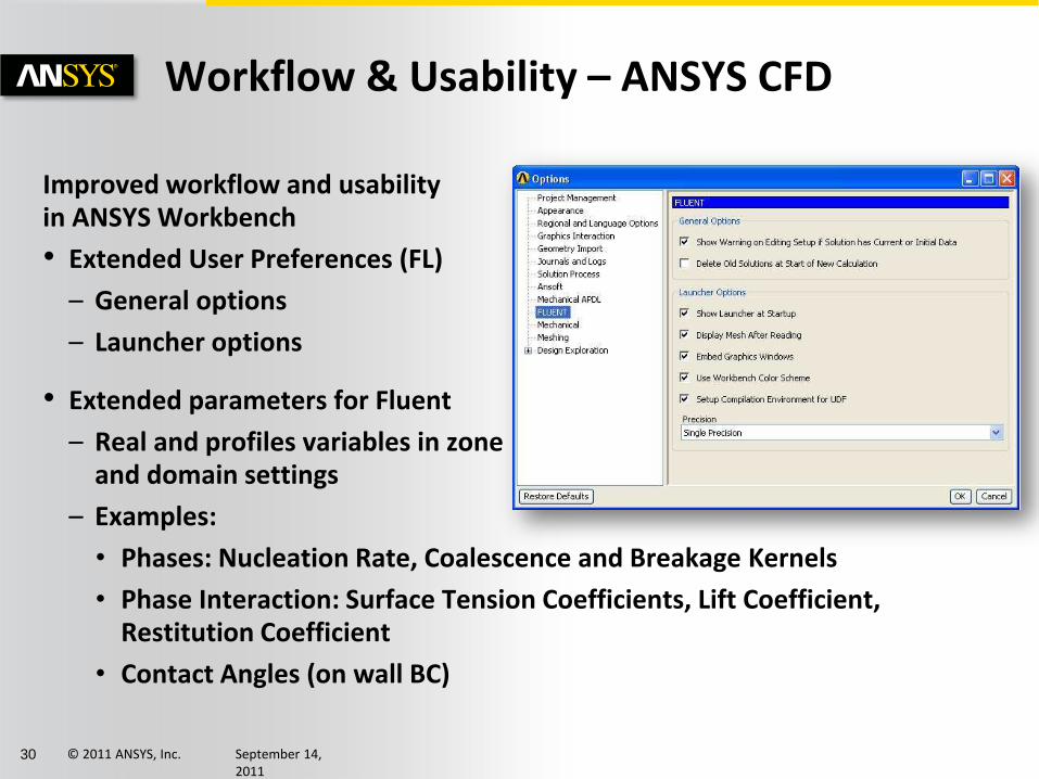
Workflow & Usability – ANSYS CFD
Improved workflow and usability in ANSYS Workbench
• Extended User Preferences (FL)
– General options
– Launcher options
• Extended parameters for Fluent
– Real and profiles variables in zone and domain settings
– Examples:
• Phases: Nucleation Rate, Coalescence and Breakage Kernels
• Phase Interaction: Surface Tension Coefficients, Lift Coefficient, Restitution Coefficient
• Contact Angles (on wall BC)

© 2011 ANSYS, Inc. September 14, 2011
31
Workflow & Usability – ANSYS CFD
Process more information per simulation (FL)
• Monitor more than a single lift, drag, or moment monitor
– Multiple monitors for each type
• Assign any variable to a custom field function for use with unsteady statistics
Export reduced data for faster file write and reduced storage needs
• Fluent – on a per cell basis to CFD Post, EnSight, and FieldView
• CFX - Output selected solution data only at boundaries during transient β
Multiple force monitors Custom field functions for statistics
Output control panel in CFX

© 2011 ANSYS, Inc. September 14, 2011
34
Multiphysics and Systems Coupling
Engineers need to accurately predict how
complex products behave in real-world
environments with real world physics.
ANSYS is continuously improving the
ease of use and efficiency of simulating
real world interactions between fluid
dynamics, structural mechanics, heat
transfer, and electromagnetics within a
single, unified engineering simulation
environment using systems coupling.

© 2011 ANSYS, Inc. September 14, 2011
35
Two-way surface force/displacement coupling between Fluent and Mechanical via Systems Coupling
• Steady/static and transient two-way FSI
• Integrated post-processing with CFD-Post
• Workbench based setup and execution
– Windows and Linux
• Alternative execution from command line
– including cross-platform
• Parallel processing with ANSYS HPC
– RSM currently not supported
• Restarts for fluid-structure interaction
• Parameterization, design exploration and optimization
Multiphysics and Systems Coupling – FSI
Non-Newtonian blood flow through a three leaf mitral valve

© 2011 ANSYS, Inc. September 14, 2011
36
Multiphysics – 1-way FSI
Significantly faster surface mapping for 1-way FSI (CFD-Post) β
• New Octree mapping method significantly faster algorithm
– Need to set Option in CFD-Post
• 1-way FSI in ANSYS Workbench uses CFD-Post ‘under-the-hood’
– Will use mapping option set by user in CFD-Post (which is stored in user preferences)
– Status message with diagnostics report indicates new mapping method is being used

© 2011 ANSYS, Inc. September 14, 2011
37
Multiphysics – Fluent-Maxwell
Complex multiphysics modeling
• New: Electromagnetic-thermal interactions inside Workbench using Fluent with Maxwell
– One-way and two-way β coupling
• Combine with 1-way FSI
β

© 2011 ANSYS, Inc. September 14, 2011
38
Solver and HPC Performance
Companies need to make informed development
decisions about their increasingly complex
products in increasingly shorter time frames.
Court
esy S
iem
ens

© 2011 ANSYS, Inc. September 14, 2011
39
Solver and HPC Performance – Adjoint Solver
Adjoint Solver for Fluent fully tested, documented, and supported at R14.0
• Provides information about a fluid system that is very difficult and expensive to gather otherwise
• Computes the derivative of an engineering quantity with respect
to inputs for the system
• Engineering quantities available
– Down-force, drag, pressure drop
• Robust for large meshes
– Tested up to ~15M cell
Shape sensitivity to down-force on a F1 car
Shape sensitivity to lift on NACA 0012
Lift Force (N)
Geometry Predicted Result
Original --- 555.26
Mod. 1 577.7 578.3
Mod. 2 600.7 599.7
Mod. 3 622 621.8

© 2011 ANSYS, Inc. September 14, 2011
40
Solver and HPC Performance Mesh Morpher and Optimizer
Fluent Mesh Morpher and Optimizer
• Create your own optimization functions using parameters
• Faster mesh deformation
• Constrain some boundaries and allow others to deform
• More easily assess the effectiveness of the optimization routine – Save and plot the value of the
objective function as a function of design iteration number
• Execute TUI commands before and after the optimization loop
Objective function definition panel
Example data showing faster mesh deformation
Objective function as a function of design stage

© 2011 ANSYS, Inc. September 14, 2011
41
Solver and HPC Performance
Focus on robustness, accuracy, and efficiency
• Improved performance (FL)
– Out of the box performance
• New defaults – 2nd order for some equations – hybrid initialization
• Solver optimizations
– Higher order term relaxation (HOTR)
• More aggressive initial settings • Improved convergence
– Migration manual
• Beta: NRBCs with PBNS (FL)
– Compatible with combustion models
RAE-2822 Airfoil M=0.73 AOA=2.8 deg
Standard @ CFL=200
HOTR @ CFL=200
Standard @ CFL=100
HOTR @ CFL=100
Normalized scales residuals comparing HOTR to standard relaxation at different CFL settings
Diverges

© 2011 ANSYS, Inc. September 14, 2011
43
Solver and HPC Performance
Improved scalability (FL)
• Scalability to higher core counts
• Simulations with monitors including plotting and printing
• Cluster-to-cluster view factor file writing optimization
Hex-core mesh, F1 car, 130 million cells monitor-enabled
0
5
10
15
20
25
30
35
0 200 400 600 800 1000
Example data for scaling with R14 monitors
3072 cores
Sample cluster-to-cluster view factor data writing using 32-way parallel and Infiniband.
0.4 million surface clusters
1.1 million surface clusters
R13
R14

© 2011 ANSYS, Inc. September 14, 2011
44
Solver and HPC Performance
Faster auto-partitioning (FL)
• Optimized for multi-core clusters
• All simulations benefit
• New default
• More constant time required with fixed overhead
Improved usability (FL)
• Better error tracking
• Latest Platform and Intel MPI versions on all platforms
Work in Progress: GPU investigation
• R14.0: Viewfactor and ray tracing calculations on GPUs (FL)b
Example viewfactor calculation times for different combinations of GPUs and CPUs

© 2011 ANSYS, Inc. September 14, 2011
45
Solver and HPC Performance
Optimize parallel partitioning in multi-core clusters (CFX)β
• Partitioner determines number of connections between partitions and optimizes part.-host assignments
Re-use previous results to initialize calculations on large problem (CFX) β
• Large case interpolation for cases with >~100M nodes
Clean up of coupled partitioning option for multi-domain cases (CFX)
• Eliminates ‘isolated’ partition spots
Compute Node 1 Compute Node 2
P1
P5
P3
P6
P2 P7
P4 P8
P1
P5 P3
P6
P2 P7
P4
P8
Partitioning step
finds adjacency
amongst partitions;
partitions with max
adjacency are
grouped on same
compute nodes

© 2011 ANSYS, Inc. September 14, 2011
46
Rotating Machinery
Rotating machinery plays a key role in many
industries, including aerospace, power
generation, automotive, marine, HVAC and
healthcare. Manufacturers are currently
challenged to improve the performance of their
machines, more than ever before.
Courtesy Siemens AG

© 2011 ANSYS, Inc. September 14, 2011
47
Rotating Machinery
Highly efficient time accurate simulations with Transient Blade Row capability (CFX)
• Several models available
– Time Transformation (TT)
• Inlet Disturbance
• Single Stage TRS
– Fourier Transformation (FT)
• Inlet Disturbance
• Single Stage TRS β
• Blade Flutter β
Surface pressure distribution (top) and monitor
point pressure (left) from an axial fan stage:
Equivalent solution with Time Transformation at
fraction of computational effort
Reference solution
without a TBR method,
requiring 180 deg model
Time Transformation
solution, requiring only
3 stator and 2 fan blades
© 2011 ANSYS, Inc. September 14, 2011
49
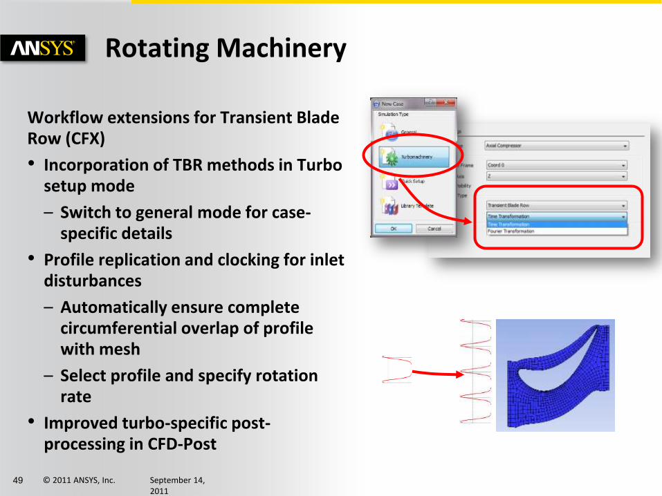
Rotating Machinery
Workflow extensions for Transient Blade Row (CFX)
• Incorporation of TBR methods in Turbo setup mode
– Switch to general mode for case-specific details
• Profile replication and clocking for inlet disturbances
– Automatically ensure complete circumferential overlap of profile with mesh
– Select profile and specify rotation rate
• Improved turbo-specific post-processing in CFD-Post

© 2011 ANSYS, Inc. September 14, 2011
52
Rotating Machinery
Highly automated blade row meshing – without sacrificing quality (TurboGrid)
• ‘ATM’ method expanded to handle (single) splitter blades
• Additional enhanced templates available
© 2011 ANSYS, Inc. September 14, 2011
58
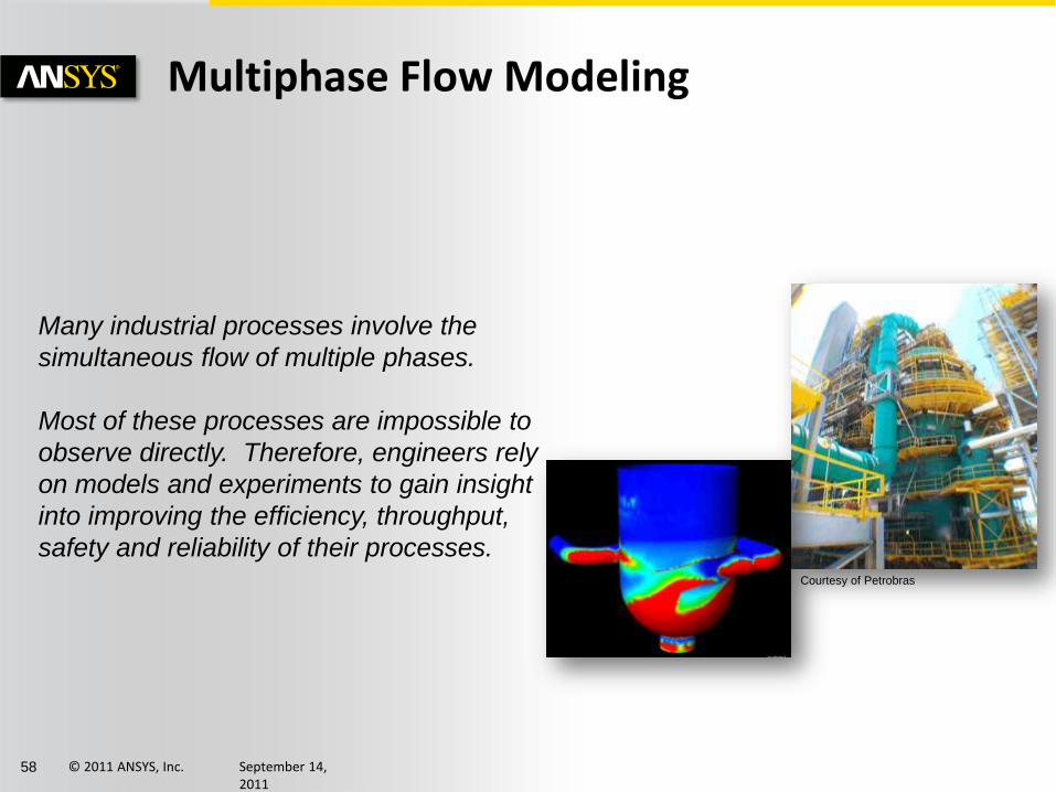
Multiphase Flow Modeling
Many industrial processes involve the
simultaneous flow of multiple phases.
Most of these processes are impossible to
observe directly. Therefore, engineers rely
on models and experiments to gain insight
into improving the efficiency, throughput,
safety and reliability of their processes. Courtesy of Petrobras
© 2011 ANSYS, Inc. September 14, 2011
59
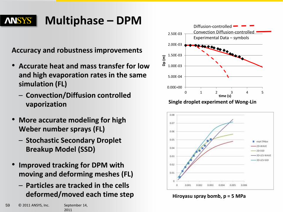
0.00E+00
5.00E-04
1.00E-03
1.50E-03
2.00E-03
2.50E-03
0 1 2 3 4 5
Dp
(m
)
time (s)
Diffusion-controlled Convection Diffusion-controlled Experimental Data – symbols
Multiphase – DPM
Accuracy and robustness improvements
• Accurate heat and mass transfer for low and high evaporation rates in the same simulation (FL)
– Convection/Diffusion controlled vaporization
• More accurate modeling for high Weber number sprays (FL)
– Stochastic Secondary Droplet Breakup Model (SSD)
• Improved tracking for DPM with moving and deforming meshes (FL)
– Particles are tracked in the cells deformed/moved each time step
Single droplet experiment of Wong-Lin
Hiroyasu spray bomb, p = 5 MPa

© 2011 ANSYS, Inc. September 14, 2011
61
Model dense particulate flows with DEM (FL)
• DEM enabled as a collision model in the DPM model panel
• Use in combination with single phase and DDPM simulations
• Works in parallel
• Particle size distributions
• Prediction of the packing limit
• Head-on collisions
• Collisions with walls
• Example applications: Bubbling and circulating fluidized beds, particle
deposition in filtering devices, particle discharge devices (silos)
Multiphase – DEM
3% fines start-up -15 sec
and 15-30 sec
Note that channeling is observed in the 15-30 sec animation
NETL Fluidized Bed Simulations using DEM with DDPM
12% fines 0-25 sec

© 2011 ANSYS, Inc. September 14, 2011
65
Multiphase – Condensation
Ability to include global effect of wall condensation without multi-phase details (CFX)
• Single phase, multiple components
– Mixture of one condensable and one or more non-condensable species
• Condensable component extracted by sink terms at walls and CHT boundaries, as function of concentration through boundary layer
– Liquid film is not modeled
• Key application: nuclear accident scenarios looking at containment pressure variation over time need to include macroscopic effect of condensation
Water condensation
near a wall at a fluid-
solid interface

© 2011 ANSYS, Inc. September 14, 2011
66
Multiphase – Free Surfaces
Better robustness and faster convergence for free surface steady-state cases using coupled VOF (FL)
• Improved in R14.0
Options for better trade-off between stability and accuracy (FL)
• Hybrid treatment of Rhie-Chow face flux interpolation with special treatment near free surfaces
Coupled VOF after 500 iterations
Coupled P-V, Segregated VOF after 1400 iterations

© 2011 ANSYS, Inc. September 14, 2011
68
Multiphase – Eulerian
Boiling model extensions, and testing (FL)
• Critical heat flux (CHF) for modeling boiling dry out conditions
• Transition smoothly between the bubbly and droplet regimes
• Boiling with bubble size distributions using interfacial area concentration (IAC) models
• Accurate interfacial areas for heat and mass transfer calculations in non-equilibrium boiling conditions
• Example applications: Nuclear industry, engine jacket cooling
Axial Position (m)
Wal
l Tem
pe
ratu
re
Test case based on the data in Hoyers et. al. showing dry out at the wall
IAC model allows bubble diameter variation at different stations along the pipe to be modeled. Data from: Bartolemei et. Al
© 2011 ANSYS, Inc. September 14, 2011
70
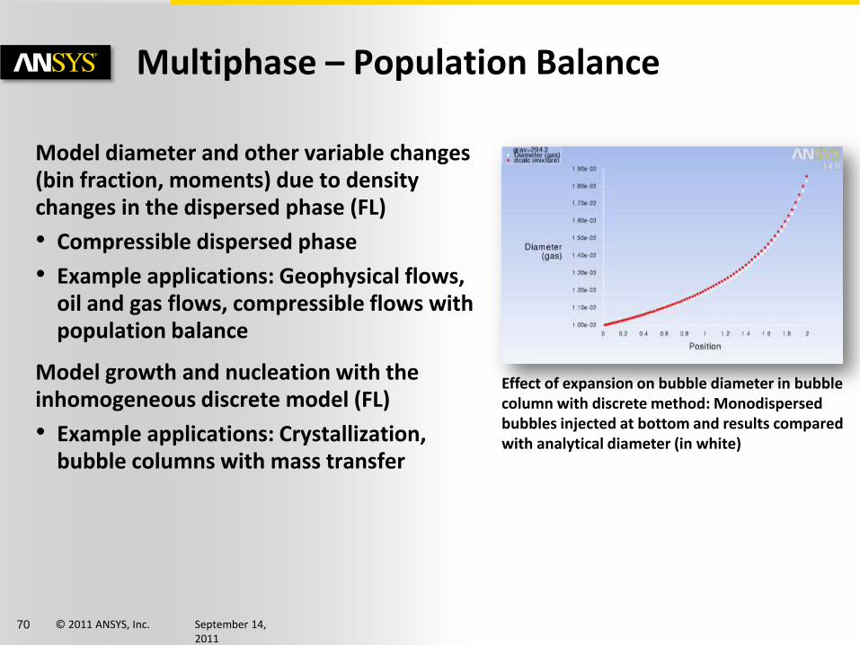
Multiphase – Population Balance
Model diameter and other variable changes (bin fraction, moments) due to density changes in the dispersed phase (FL)
• Compressible dispersed phase
• Example applications: Geophysical flows, oil and gas flows, compressible flows with population balance
Model growth and nucleation with the inhomogeneous discrete model (FL)
• Example applications: Crystallization, bubble columns with mass transfer
Effect of expansion on bubble diameter in bubble column with discrete method: Monodispersed bubbles injected at bottom and results compared with analytical diameter (in white)
© 2011 ANSYS, Inc. September 14, 2011
71
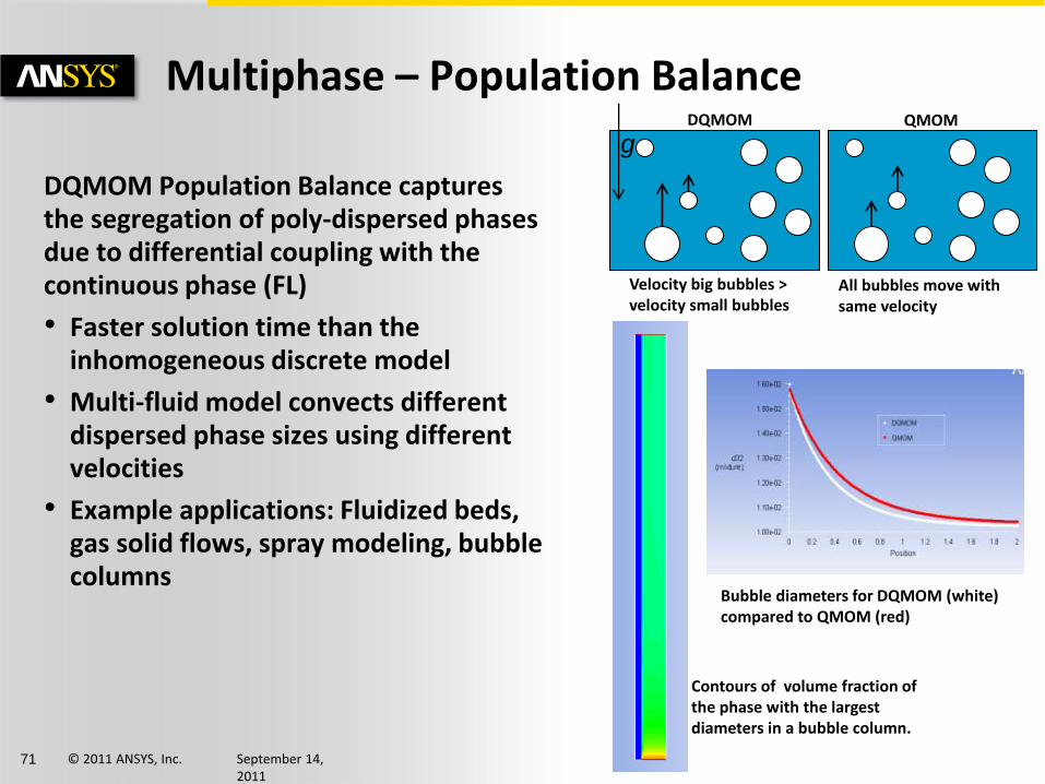
Multiphase – Population Balance
DQMOM Population Balance captures the segregation of poly-dispersed phases due to differential coupling with the continuous phase (FL)
• Faster solution time than the inhomogeneous discrete model
• Multi-fluid model convects different dispersed phase sizes using different velocities
• Example applications: Fluidized beds, gas solid flows, spray modeling, bubble columns
Velocity big bubbles > velocity small bubbles
All bubbles move with same velocity
DQMOM QMOM
g
Bubble diameters for DQMOM (white) compared to QMOM (red)
Contours of volume fraction of the phase with the largest diameters in a bubble column.

© 2011 ANSYS, Inc. September 14, 2011
72
Multiphase – Eulerian Wall Film
Eulerian Wall Film Model for rain water management, deicing and other applications
• Available models:
– Momentum coupling
– DPM coupling
• Particle collection, splashing and shearing
– Heat transfer
Contours of temperature in an Eulerian Wall Film with heat transfer case
film
Q = 3000 W
air solid
liquid water injected
KCm
QT
P
film 75400001.0
3000
The wall film on a car mirror with droplets released due to wind shear

© 2011 ANSYS, Inc. September 14, 2011
73
Comprehensive CFD Capabilities
Manufacturing companies today
face many challenges, ranging from
increased product complexity to
tightened quality requirements to
yield and productivity pressures.
As product complexity increases
and the margin for error decreases,
CFD must rise to meet growing
demands for comprehensive and
advanced product capabilities.
Court
esy B
org
Warn
er
Tu
rbo &
Em
issio
ns S
yste
ms.
Court
esy M
TU
Aero
Engin
es G
mbH
.

© 2011 ANSYS, Inc. September 14, 2011
74
Comprehensive CFD – Motion
Improved accuracy with simplicity of immersed solids (CFX)
• Addition of boundary model for more realistic velocity forcing with immersed solids
– Track nodes nearest to immersed solid
– Assume constant shear (laminar) or use scalable wall function (turbulent) to modify forcing at immersed solid ‘wall’
• Can improve immersed solid predictions significantly
– Continuing development for further improvements and broader applications
Boundary-fitted mesh
Immersed Solid (default)
Immersed Solid with Boundary Model

© 2011 ANSYS, Inc. September 14, 2011
78
Comprehensive CFD – Turbulence
Focus on wall treatment accuracy (FL)
• More accurate rough wall treatment for epsilon-based models
– Avoids reduction in roughness when the near-wall mesh is refined
– New default for all simulations using rough wall treatment
• Reduced sensitivity to the near-wall mesh density for the Spalart-Allmaras model
– New enhanced wall treatment is the default for S-A turbulence
model
Turbulent flow over a flat plate with roughness and heat transfer
R14 wall treatment R13 default treatment
Sensitivity of the skin friction coefficient to mesh density in an incompressible flat boundary layer modeled with Spalart-Allmaras

© 2011 ANSYS, Inc. September 14, 2011
80
Comprehensive CFD – Turbulence
More accurate solution of high Re wall bounded flows using LES (FL)
• Algebraic Wall Modeled LES (WMLES) formulation based on Smagorinsky model
• Benefits gas turbine combustors and other internal flow applications
Apply scale-resolving turbulence models only locally, as required, to balance cost vs. accuracy (CFX) β
• Zonal LES model using turbulence forcing
• Forcing zone defined by logical CEL function
Flow over a wall mounted hump
Contours of Q criterion
A mixing layer with resolved turbulence using SAS initiated by the forcing model

© 2011 ANSYS, Inc. September 14, 2011
81
Comprehensive CFD – Acoustics
Validations and model extensions (FL)
• Convective effect for FW-H acoustics solver
– Option to include the effect of far-field velocity on the generated sound for the Ffowcs-Williams & Hawkins solver
– Improves accuracy when modeling aeroacoustics and external flows
• Model Doppler effects due to the relative motion of acoustic sources and receivers (FL)
– For example: Sound from a source moving with a constant speed (airplane, car)
M=0.2
FWH source surface,
R=1m
Receivers,
R=3m
2D monopole with convection
OASPL – overall sound pressure level
M=0.4 Moving receiver
Source Sound pressure compared with analytic solution at approach and departure (Doppler effect different frequencies)
Acoustics directivity

© 2011 ANSYS, Inc. September 14, 2011
82
2x2 3x3 6x6
Serial/Old 218.63 s 269.95s 536.32s
Serial/New 202.40s 241.56s 429.40s
Parallel 2-proc/Old
86.4s 107.4s 205.3s
Parallel 2-proc/New
80.7s 98.4s 167.2s
Comprehensive CFD – Radiation
More Efficient Discrete Ordinates Radiation (FL)
• DO radiation calculations ignore solid zones not participating in radiation or participating in heat transfer by conduction only
• Avoids unnecessary CPU time and memory allocations
• Performance improvement varies depending on specifics of case
– Up to 20% improvement for test cases
Sample data for a 3D case with 5 solid zones

© 2011 ANSYS, Inc. September 14, 2011
83
Comprehensive CFD – Shell Conduction
Shell conduction: Improved accuracy and ability to include combustion (FL)
• Non-premixed and partially-premixed combustion models
• Example applications: Gas turbines, those with thin walls and combustion
Improved shell conduction usability (FL)
• Updated documentation for wall temperature variables and shell zone and thin wall post-processing
• Post-process the external wall temperature if shell conduction is applied on a one-sided-wall
Oxidizer(air) V=0.1 m/s, T = 300K Mean Mixture Fraction=0
Fuel, V=1 m/s T= 300K Mean Mixture Fraction=1
External Wall with convective BC h=2, Tinf= 300K
Temperature on a mid-geometry surface
Geometry and details for shell conduction with non-premixed combustion test case

© 2011 ANSYS, Inc. September 14, 2011
85
Comprehensive CFD – Reacting Flows
Focus on Validation and Verification (FL)
• Real gas models:
– RCM1, RCM3
• Surface chemistry model:
– Kleijn CVD
• Turbulent non-premixed flame model:
– Sydney bluff body flame
• Turbulent premixed flame model:
– Chen F3
• Internal Combustion Engines
Example simulation results for the Kleijn CVD verification for surface chemistry
© 2011 ANSYS, Inc. September 14, 2011
88
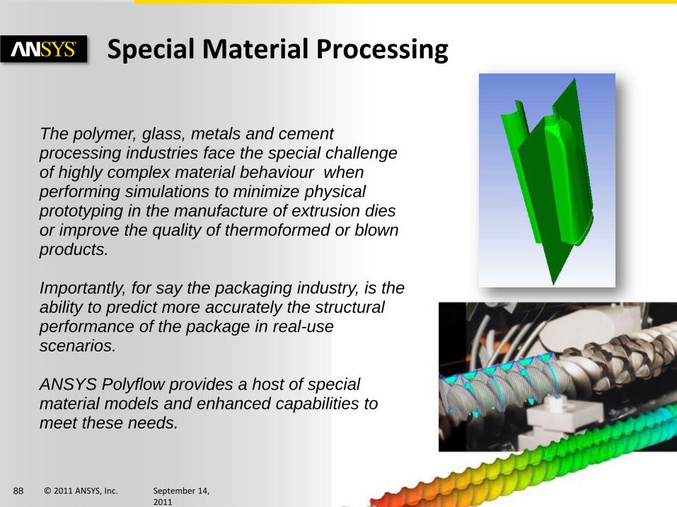
The polymer, glass, metals and cement processing industries face the special challenge of highly complex material behaviour when performing simulations to minimize physical prototyping in the manufacture of extrusion dies or improve the quality of thermoformed or blown products.
Importantly, for say the packaging industry, is the
ability to predict more accurately the structural performance of the package in real-use scenarios.
ANSYS Polyflow provides a host of special
material models and enhanced capabilities to meet these needs.
Special Material Processing

© 2011 ANSYS, Inc. September 14, 2011
94
• Thickness data from ANSYS POLYFLOW can be sent to ANSYS Mechanical and ANSYS Explicit Dynamics via an automatic connection
• Complete Virtual Prototyping and Testing capability in ANSYS Workbench for packaging manufacturing:
– Simulate blow molding or thermoforming process to get final thickness distribution with Polyflow
– Based on Polyflow predicted variable thickness, perform stress and deformation analysis
• Top load stress analysis with ANSYS Mechanical shown here
Virtual Prototyping for Packaging Applications - Mechanical

© 2011 ANSYS, Inc. September 14, 2011
95
• Where the deformation or loading rate are larger, then transfer the Polyflow thickness data to Explicit Dynamics system in Workbench
– Explicit Dynamics is available as part of ANSYS Explicit STR and ANSYS AUTODYN
• Here we will load a blown part (created from Polyflow) with a rigid plate (in green in mesh plot)
– Loading normal to the plate
Virtual Prototyping for Packaging Applications – Explicit Dynamics

© 2011 ANSYS, Inc. September 14, 2011
96
ANSYS Fluid Dynamics 14 contains enhancements in all products…
• ANSYS Fluent, ANSYS CFX, ANSYS CFD-Post
• ANSYS Turbogrid
• ANSYS Polyflow
… for rapid and robust meshing, workflow and usability, HPC and solver speed, rotating machinery, automotive and multiphase applications as well as overall to provide comprehensive CFD.
Summary

© 2011 ANSYS, Inc. September 14, 2011
97
Release Timeline
2011 – R14 2012 – R14.5 2013 - R15 2014 - R16
Large release
Fluent, CFX,
Polyflow
Rapid meshing
Adjoints
System coupling
Industry specific
…
Development
starting soon
Feature release
Fluent, CFX,
Polyflow
Hybrid vehicles
Turbomachinery
Full systems
….
Release the results of
today’s R&D topics!
Fluent, CFX, Polyflow
… and …
next generation CFD
Advanced physics
Best in class numerics
Parallel meshing
Reduced order modeling
Design automation
Co-simulation
Parameterization
…

© 2011 ANSYS, Inc. September 14, 2011
98
ANSYS Fluid Dynamics Update