ansi/bicsi-001-2009,€¢ ansi/tia/eia-606-a, administration standard for commercial...
TRANSCRIPT


ANSI/BICSI-001-2009, Information Transport
Systems Design Standard for K-12 Educational Institutions
Terry W. HochbeinRCDD/NTS/OSP
ATSR Architects/Engineers

PURPOSE
• This Standard specifies minimum requirements and guidelines for the design of Information Transport Systems (ITS) infrastructure for K-12 educational institutions. It is intended to be used by K-12 facility owners, facility operators, architects, engineers, telecommunications and information technology (IT) consultants, project managers, and telecommunications/IT technology installers. It is not intended to be the sole source of information for the design of ITS for K-12 institutions
Forward
K-12 DESIGN STANDARD
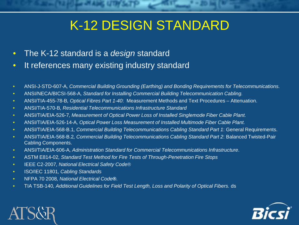
• The K-12 standard is a design standard• It references many existing industry standard
• ANSI-J-STD-607-A, Commercial Building Grounding (Earthing) and Bonding Requirements for Telecommunications.• ANSI/NECA/BICSI-568-A, Standard for Installing Commercial Building Telecommunication Cabling.• ANSI/TIA-455-78-B, Optical Fibres Part 1-40: Measurement Methods and Text Procedures – Attenuation.• ANSI/TIA-570-B, Residential Telecommunications Infrastructure Standard• ANSI/TIA/EIA-526-7, Measurement of Optical Power Loss of Installed Singlemode Fiber Cable Plant.• ANSI/TIA/EIA-526-14-A, Optical Power Loss Measurement of Installed Multimode Fiber Cable Plant.• ANSI/TIA/EIA-568-B.1, Commercial Building Telecommunications Cabling Standard Part 1: General Requirements.• ANSI/TIA/EIA-568-B.2, Commercial Building Telecommunications Cabling Standard Part 2: Balanced Twisted-Pair
Cabling Components.• ANSI/TIA/EIA-606-A, Administration Standard for Commercial Telecommunications Infrastructure.• ASTM E814-02, Standard Test Method for Fire Tests of Through-Penetration Fire Stops• IEEE C2-2007, National Electrical Safety Code• ISO/IEC 11801, Cabling Standards• NFPA 70 2008, National Electrical Code®.• TIA TSB-140, Additional Guidelines for Field Test Length, Loss and Polarity of Optical Fibers. ds

K-12 DESIGN STANDARDGeneric Infrastructure
Horizontal Cabling Multi-User
Telecommunications Outlet Assembly (MUTOA)
Consolidation Point (CP) Backbone Cabling Telecommunications
Enclosures Test Requirements
Labeling Grounding & Bonding Firestop Systems Security Systems Wireless System Master Clock System Distance Learning
The generic infrastructure specified includes the following:
K-12 DESIGN STANDARDEducational Spaces
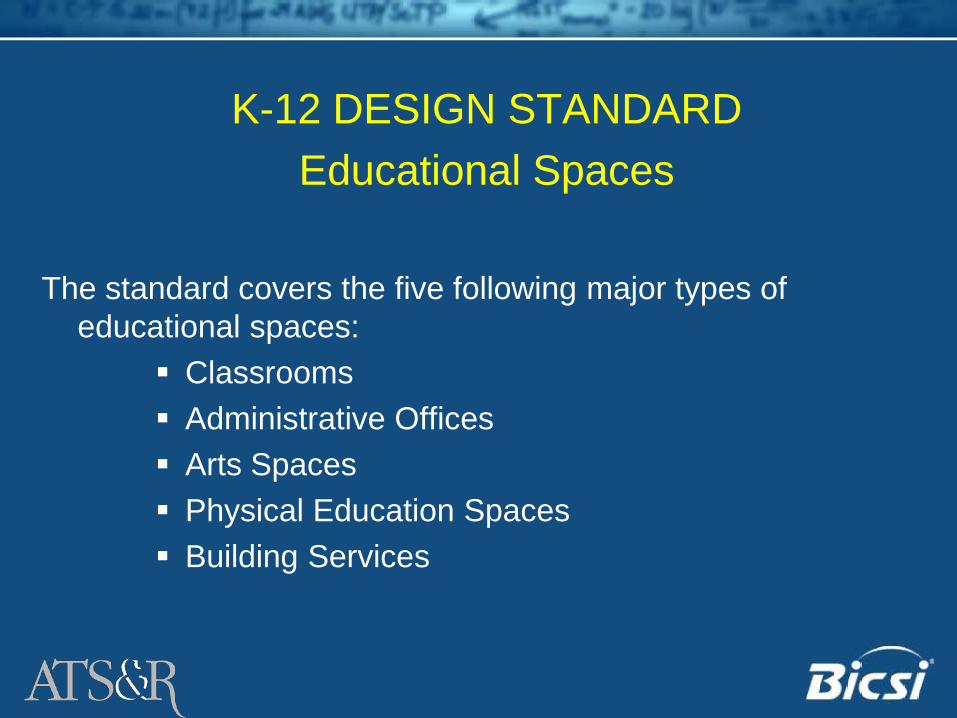
The standard covers the five following major types of educational spaces:
Classrooms Administrative Offices Arts Spaces Physical Education Spaces Building Services
K-12 DESIGN STANDARDEducational Spaces
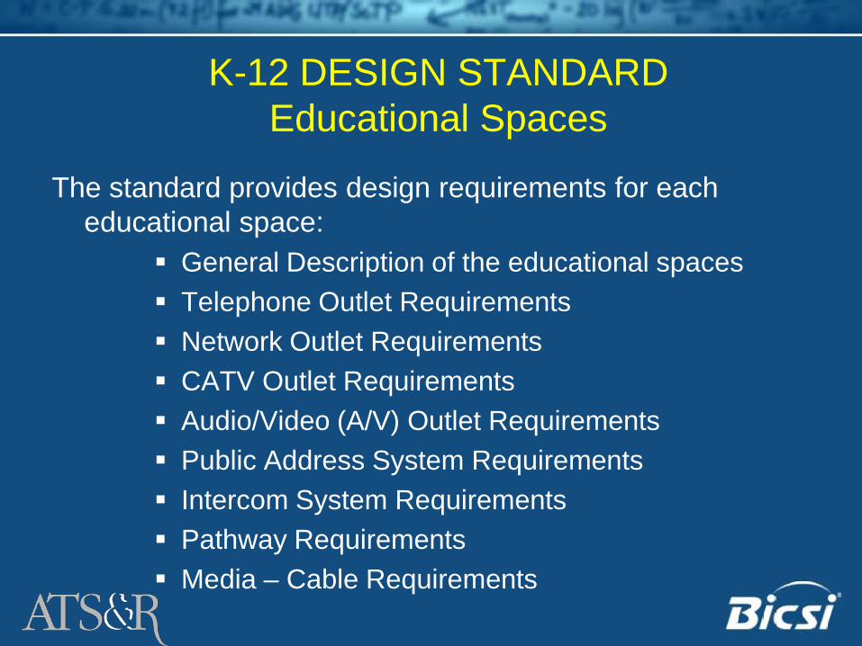
The standard provides design requirements for each educational space:
General Description of the educational spaces Telephone Outlet Requirements Network Outlet Requirements CATV Outlet Requirements Audio/Video (A/V) Outlet Requirements Public Address System Requirements Intercom System Requirements Pathway Requirements Media – Cable Requirements
K-12 DESIGN STANDARDEducational Spaces - Classrooms
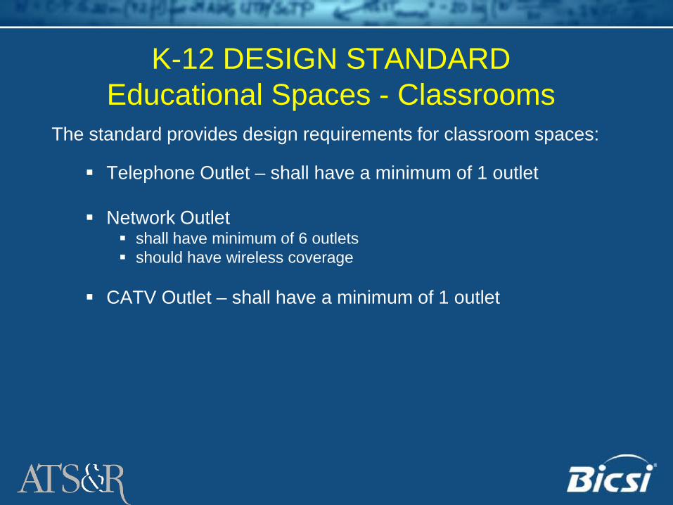
The standard provides design requirements for classroom spaces:
Telephone Outlet – shall have a minimum of 1 outlet
Network Outlet shall have minimum of 6 outlets should have wireless coverage
CATV Outlet – shall have a minimum of 1 outlet
K-12 DESIGN STANDARDEducational Spaces – Classrooms (cont.)
The standard provides design requirements for classroom spaces:
Audio/Video (A/V) should have provisions for electric ceiling mounted or wall mounted
screen should have cabling for a projector (typically ceiling mounted) and
speakers from the teaching position should have USB connections when intelligent whiteboards are
deployed should have provisions for musical instrument digital interfaces (MIDI)
when deployed should have mounting hardware, ITS and control cables when monitors
are used and shared by a computer, television and the A/V system should have a sound reinforcement system for recording and playback
of in-room programming and playback of recorded material. the sound reinforcement system shall have an amplifier and a
minimum of one microphone

K-12 DESIGN STANDARDEducational Spaces - Classrooms (cont.)
The standard provides design requirements for classroom spaces: Public Address System – shall be extended into the classroom Intercom System – a public address, intercom, telephone should
be provided Pathway Requirements – outlets shall have conduits or
equivalent pathways extended to accessible ceiling Media
Balanced Twisted Pair – shall be a minimum of Cat 5E/Class D Multimode Optical Fiber
62.5/125 - shall be a minimum of 200/500MHz per Km bandwidth 50/125 - shall be a minimum of 500/500MHz per Km bandwidth
SVGA cable with 15 pin connectors and an S-video cable for projector Series 6 quad-shield coax Proprietary cables shall conform to manufactures specifications

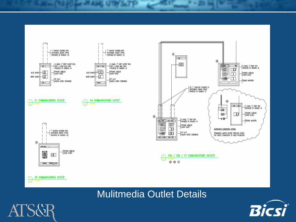
Mulitmedia Outlet Details

Thank You!
• K-12 Standards Subcommittee Members– Especially: Todd Taylor, Editor John Kacperski, Secretary

Post Secondary Standard
• Currently under development• Expected publication Fall 2010• Terry Hochbein, Chairman• Mark King, Secretary

Questions?
Terry W. Hochbein, RCDD NTS/OSP» Senior Technology Designer» ATSR Architects/Engineers
763.525.5644 Office612.817.9123 [email protected]


BICSI Data Center Standard Update
Jonathan Jew – J&M Consultants, Inc.John Kacperski – UCLA Medical Center
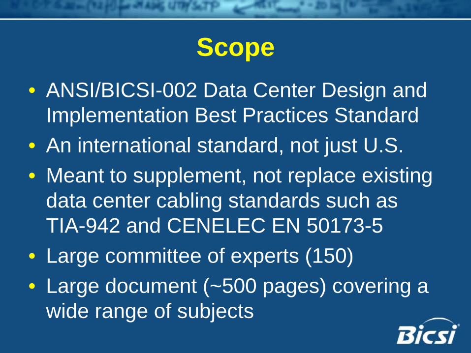
Scope• ANSI/BICSI-002 Data Center Design and
Implementation Best Practices Standard• An international standard, not just U.S.• Meant to supplement, not replace existing
data center cabling standards such as TIA-942 and CENELEC EN 50173-5
• Large committee of experts (150) • Large document (~500 pages) covering a
wide range of subjects

Subjects Covered• Site Selection• Architectural and Structural Design• Electrical Systems• Mechanical Systems (i.e., HVAC)• Fire Protection and Security• Building Automation Systems• Commissioning• Maintenance

Subjects Covered• Telecommunications
– Access Providers & Entrance Facilities– Telecom Spaces– Cabinets & Racks– Cabling Pathways– Telecom Cabling– Field Testing– Telecom Administration
• Information Technology

Status• Completed 3rd Industry Ballot• Balloting continues until consensus is
reached among subcommittee members and canvass list members
• Desire is to publish as soon as possible


NECA/BICSI-607-2009Telecommunications Bonding and Grounding Planning and
Installation Methods for Commercial Buildings

Highlights of NECA/BICSI 607
• Busbar to Equipment• New Terminology• Emphasis on Installation Techniques

Telecommunications RoomGrounding Equalizer
(GE)
Telecommunications Bonding Backbone (TBB)
Bonding Jumper
Telecommunications Grounding Busbar
(TGB)
Unit Bonding Conductor (UBC)
Vertical Rack Grounding
Busbar (RGBV)
Telecommunication Equipment Bonding Conductor (TEBC)
Rack Bonding Conductor (RBC)

Equipment & Rack Bonding Option “1”
• Option “1” • Equipment attached to a
rack bonding conductor (RBC)– From rack/cabinet to TEBC
• Requires multiple cutting and stripping of the RBC
• Requires multiple irreversible connections
* NECA/BICSI-607

Equipment & Rack Bonding Option “2”
• Option “2” • Horizontal rack grounding
busbar• mounted on top or bottom
of the rack/cabinet• equipment bonded directly
to the busbar with a unit bonding conductor (UBC)
• UBCs may be longer• Adds to the complexity of
cable management
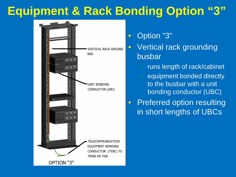
Equipment & Rack Bonding Option “3”
• Option ”3”• Vertical rack grounding
busbar– runs length of rack/cabinet– equipment bonded directly
to the busbar with a unit bonding conductor (UBC)
• Preferred option resulting in short lengths of UBCs
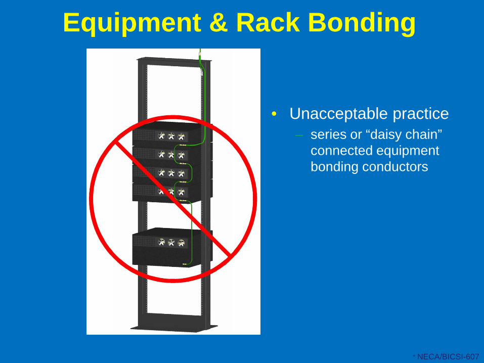
Equipment & Rack Bonding
• Unacceptable practice– series or “daisy chain”
connected equipment bonding conductors
* NECA/BICSI-607
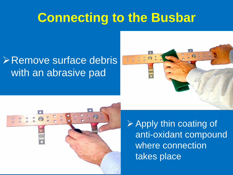
Connecting to the Busbar
Remove surface debris with an abrasive pad
Apply thin coating of anti-oxidant compound where connection takes place

Connecting to the BusbarAttach lugs to the busbarstainless steel or silicon
bronze hardware tighten to the appropriate
torque rating

Summary
• These are just a few examples of the additions made …..
• Hopefully, these allow for a better understanding of proper bonding and grounding techniques


ANSI/NECA/BICSI-568, Installing Commercial BuildingTelecommunications Cabling
Bob Jensen, RCDD

Purpose• This standard not only covers the
installation and safety requirements for telecommunications cabling, it focuses on criteria that aid in delivering performance levels expected by end-users
• To promote telecommunications infrastructure installation training– National Electrical Code (NEC) references– Provide guidance to installation trades

History
1998BOD approved joint standard with NECA
2001Joint standard published
2006Joint standard revised
The first standard to address the importance of proper telecommunications infrastructure installation
ANSI/NECA/BICSI-568 is based upon BICSI’s Telecommunications CablingInstallation Manual

Participating BICSI Members• Ray Keden• Al Feaster• Donna Ballast• Bob Jensen• Ed Phillips• Bob Faber• Phil Janeway• Ray Emplit
• Richard Anderson• Joe O’Brien• Mel Lesperance• Pete Olders• Alvin Emmett• Darron Wright• Don Wright• Charlie Mann

ScopeThis Standard describes minimum requirements and procedures for installing the infrastructure for telecommunications including balanced twisted pair copper cabling and optical fiber cabling that transport telecommunications signals (e.g., voice, data, video). Installers should always follow applicable codes and manufacturers’ instructions. This Standard is intended to be used in describing a “neat and workmanlike manner” as referenced by ANSI/NFPA 70, the National Electrical Code (NEC).

The NEC Relationship800.24 Mechanical Execution of Work.Communications circuits and equipment shall be installed in a neat and workmanlike manner.
FPN: Accepted industry practices are described in ANSI/NECA/BICSI 568-2006, Installing Commercial Building Telecommunications Cabling
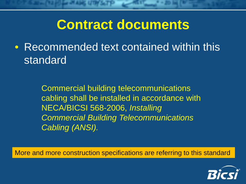
Contract documents• Recommended text contained within this
standard
Commercial building telecommunicationscabling shall be installed in accordance withNECA/BICSI 568-2006, InstallingCommercial Building TelecommunicationsCabling (ANSI).
More and more construction specifications are referring to this standard
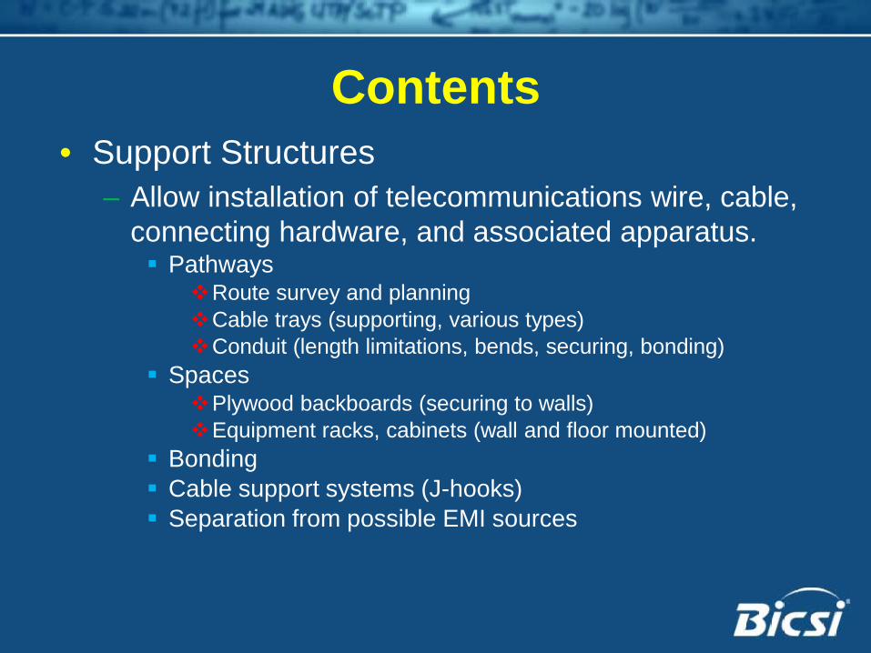
Contents• Support Structures
– Allow installation of telecommunications wire, cable, connecting hardware, and associated apparatus. Pathways
Route survey and planningCable trays (supporting, various types)Conduit (length limitations, bends, securing, bonding)
SpacesPlywood backboards (securing to walls)Equipment racks, cabinets (wall and floor mounted)
Bonding Cable support systems (J-hooks) Separation from possible EMI sources

Contents• Pulling cable
– Setup Horizontal and backbone cables Horizontal and vertical pathways Open ceiling
– Preferred optical fiber premises cable jacket colors• Firestopping
– Re-establishing the integrity of fire rated walls, floors, and ceilings is an essential part of a cabling installation.
– Ten basic types of firestop– Typical installations illustrated

Contents• Cable Terminations and Splicing
– Fiber and Copper– Color codes– Dressing cables for termination
• Installation verification– Visual inspection and performance test
documentation are required for proof of proper installation conformance

Contents• Testing
– Copper Permanent link Channel
– Optical fiber OLTS, OTDR optional OLTS – One jumper reference; mandrel on launch cord Length, polarity, attenuation

Status• Can be obtained from BICSI
– https://www.bicsi.org/standards/order_now.aspx
• Due for revision by 2011• Items to cover
– Category 6A– OM4– Other items of interest
• Contact:– [email protected]

