annex 3 draft guidelines for verification of damage stability … guidelines for... ·...
TRANSCRIPT
SLF 54/5 Annex 3, page 1
I:\SLF\54\5.doc
ANNEX 3
DRAFT GUIDELINES FOR VERIFICATION OF DAMAGE STABILITY REQUIREMENTS FOR TANKERS
GUIDELINES FOR VERIFICATION OF STABILITY ON TANKERS
PART 1
GUIDELINES FOR PREPARATION AND APPROVAL OF TANKER DAMAGE STABILITY CALCULATIONS
Guideline for scope of damage stability verification on new oil tankers, chemical tankers and gas carriers*
1 Application This recommendation applies for new oil tankers, chemical tankers and gas carriers contracted for construction* on or after 1 January 2010 subject to review of impact on ships undergoing approval and delivering after said date.
________________ * The "contracted for construction" date means the date on which the contract to build the ship is signed between the prospective owner and the shipbuilder. For further details regarding the date of "contract for construction", refer to Procedural Requirement (PR) No. 29.
2 Reference 2.1 IMO instruments 2.1.1 General instruments SOLAS chapter II-1, regulations 4.1, 4.2, 5-1 and 19; Resolution MSC.143(77), "Adoption of amendments to the Protocol of 1988 relating to the International Convention on Load Lines, 1966", regulations 27(2), 27(3), 27(11), 27(12) and 27(13)1; Resolution MSC.281(85), "Explanatory Notes to the SOLAS chapter II-1 Subdivision and Damage Stability Regulations" – special attention should be paid to Guidelines for the Preparation of Subdivision and Damage Stability Calculations specified in the appendix; Resolution MSC.245(83), "Recommendation on a Standard Method for Evaluating Cross-Flooding Arrangements"; MSC.1/Circ.1245, "Guidelines for Damage Control Plans and Information to the Master"; and MSC.1/Circ.1229, "Guidelines for the Approval of Stability Instruments", paragraph 4.
* Excluding combination carriers. 1 The application of ICLL Protocol 1988, reg. 27 is explained in annex 1.
SLF 54/5 Annex 3, page 2
I:\SLF\54\5.doc
Note: Rev.1 applies to new oil tankers, chemical tankers and gas carriers contracted for construction on or after 1 January 2011, subject to review of impact on ships undergoing approval and delivering after the said date. 2.1.2 Instrument applicable to oil tankers MARPOL Annex I, regulation 28. 2.1.3 Instruments applicable to gas carriers International Code for the Construction and Equipment of Ships Carrying Liquefied Gases in Bulk (IGC Code), Chapter 2, paragraphs 2.1, 2.4, 2.5, 2.6.2, 2.6.3, 2.7, 2.8 and 2.9; and MSC/Circ.406/Rev.1, "Guidelines on Interpretation of the International Code for the Construction and Equipment of Ships Carrying Dangerous Chemicals in Bulk (IBC Code) and the International Code for the Construction and Equipment of Ships Carrying Liquefied Gases in Bulk (IGC Code) and Guidelines for the Uniform Application of the Survival Requirements of the IBC and IGC Codes". 2.1.4 Instruments applicable to chemical tankers International Code for the Construction and Equipment of Ships Carrying Dangerous Chemicals in Bulk (IBC Code), Chapter 2, paragraphs 2.1, 2.4, 2.5, 2.6.2, 2.7, 2.8 and 2.9; and MSC/Circ.406/Rev.1, "Guidelines on Interpretation of the International Code for the Construction and Equipment of Ships Carrying Dangerous Chemicals in Bulk (IBC Code) and the International Code for the Construction and Equipment of Ships Carrying Liquefied Gases in Bulk (IGC Code) and Guidelines for the Uniform Application of the Survival Requirements of the IBC and IGC Codes". 2.2 IACS resolutions UR L5 "Onboard Computers for Stability Calculations"; PR7 "Procedure for the Training and Qualification of Survey and Plan Approval Staff"; and UI SC 156 "Doors in watertight bulkheads of cargo ships and passenger ships". 3 General 3.1 Education and training 3.1.1 Plan approval staff engaged in damage stability verification of new oil tankers, chemical tankers and gas carriers should have as minimum the following formal educational background: .1 a degree or equivalent from a tertiary institution recognized within the field
of marine engineering or naval architecture; and
.2 competent in the English language commensurate with their work.
SLF 54/5 Annex 3, page 3
I:\SLF\54\5.doc
3.1.2 Plan approval staff engaged in damage stability verification of new oil tankers, chemical tankers and gas carriers should be trained according to theoretical and practical modules defined by the Administration or RO to acquire and develop general knowledge and understanding applicable to the a/m types of ship and stability assessment according to the IMO and IACS Rules and Instruments and Resolutions referred in paragraph 2 above. 3.1.3 Methods of training may include monitoring, testing, etc., on regular basis according to the Administration's or RO's system. Evidence of training provided should be documented. 3.1.4 Updating of qualification may be done through the following methods: .1 self-study;
.2 extraordinary seminars in case of significant changes in the international
Conventions, Codes, etc.; and
.3 special training on specific work, which is determined by a long absence of practical experience.
Maintenance of qualification should be verified at annual performance review. 3.2 Scope of stability verification 3.2.1 The scope of damage stability verification is determined by the required damage stability standards (applicable damage stability criteria) and aims at providing the ship's master with a sufficient number of approved loading conditions to be used for the loading of the ship. In general, for non-approved loading conditions (by the Administration or RO), approved KG/GM limit curve(s) or approved stability instrument software satisfying the stability requirements (intact and damage) for the draught range to be covered should be used to verify compliance on board. 3.2.2 Within the scope of the verification determined as per the above, all potential or necessary damage scenarios should be determined and assessed taking into account the damage stability criteria. 3.2.4 Damage stability verification and approval requires a review of submitted calculations and supporting documentation with independent check calculations to confirm damage stability calculation results comply with relevant stability criteria. 3.2.5 Examination and approval of the stability instrument software installed on board (and to be used for assessing intact and damage stability) should also be carried out. A stability instrument comprises hardware and software. The accuracy of the computation results and actual ship data used by the software is to be verified. 3.3 Assumptions 3.3.1 For all loading conditions, the initial metacentric height and the righting lever curve should be corrected for the effect of free surfaces of liquids in tanks. 3.3.2 Superstructures and deckhouses not regarded as enclosed can be taken into account in stability calculations up to the angle at which their openings are flooded. Flooding points (including windows) incapable of weathertight closure to be included in any list determined in accordance with paragraph 3.4.2.6. Full compliance with residual stability criteria must be achieved before any such point becomes immersed.
SLF 54/5 Annex 3, page 4
I:\SLF\54\5.doc
3.3.3 When determining the righting lever (GZ) of the residual stability curve, the constant displacement (lost buoyancy) method of calculation should be used (see paragraph 6.1). 3.3.4 Conditions of loading and instructions provided by the submitter for use of the applicable KG/GM limit curve(s) and variation of loading patterns and representative cargoes are taken to be representative of how the ship will be operated. 3.4 Documentation to be submitted for review 3.4.1 Presentation of documents The documentation should begin with the following details: principal dimensions, ship type, designation of intact conditions, designation of damage conditions and pertinent damaged compartments, KG/GM limit curve(s). 3.4.2 General documents and supporting information .1 lines plan, plotted or numerically; .2 hydrostatic data and cross curves of stability (including drawing of the
buoyant hull); .3 definition of watertight compartments with moulded volumes, centres of
gravity and permeability; .4 layout plan (watertight integrity plan) for the watertight compartments with
all internal and external opening points including their connected sub-compartments, and particulars used in measuring the spaces, such as general arrangement plan and tank plan;
.5 Stability Booklet/Loading Manual including at least fully loaded
homogeneous condition at summer load line draught (departure and arrival) and other intended operational conditions;
.6 coordinates of opening points with their level of tightness
(e.g. weathertight, unprotected)2, including reference to the compartment that the opening is connected to;
.7 watertight door location; .8 cross and down-flooding devices and the calculations thereof according to
resolution MSC.245(83) with information about diameter, valves, pipe lengths and coordinates of inlet/outlet. Cross/down flooding should not be considered for the purpose of achieving compliance with the stability criteria (see also paragraph 9.2);
.9 pipes in damaged area when the breaching of these pipes results in
progressive flooding (see paragraph 10.1); .10 damage extents and definition of damage cases; and
2 Details of watertight, weathertight and unprotected openings should be included in the Damage Control
Plan and Damage Control Booklet in accordance with MSC.1/Circ.1245.
SLF 54/5 Annex 3, page 5
I:\SLF\54\5.doc
.11 any initial conditions or restrictions which have been assumed in the derivation of critical KG or GM data, and which must therefore be met in service.
The cases and extent of progressive flooding assumed in the damage stability analysis should be indicated in the Damage Control Booklet and the Documents for Submission in accordance with the appendix to MSC.281(85). Arrangements to prevent further flooding are to be indicated on the Damage Control Plan and in the Damage Control Booklet. 3.4.3 Special documents 3.4.3.1 Documentation .1 Design documentation: damage stability calculations (including residual
stability curves), the arrangements, configuration and contents of the damaged compartments, and the distribution, relative densities and the free surface effect of liquids.
.2 Operational documentation: loading and stability information booklet
(stability booklet), Damage Control Plan; and Damage Control Booklet2. 3.4.3.2 Special consideration For intermediate flooding stages before cross-flooding (see paragraphs 6.8 and 9.2) or before progressive flooding (see paragraph 6.9), an appropriate scope of the documentation covering the aforementioned items is needed in addition. The intermediate stages for cargo outflow and seawater inflow should be checked. If any stability criteria during intermediate stages shows more severe values than in the final stage of flooding this intermediate stages should also be submitted. 4 Operating Limits – Descriptions/Assumptions In considering the scope of the verification to be conducted, consideration of the operating limits is needed. The following loading options should be permitted: .1 service loading conditions identical to the approved loading conditions of
the stability booklet (see paragraph 4.2); or .2 service loading conditions complying with the approved intact and damage
stability limiting curves (where provided) (see paragraph 4.3); or .3 service loading conditions which have been checked with an approved
onboard stability software with the capability to perform damage stability calculations (Type 2 or Type 3 of IACS UR L5, Rev.2, Corr.1, Nov 2006) either based on KG/GM limit curve(s) or based on direct damage stability assessment (see paragraph 4.5).
If the above-mentioned proof of compliance is not possible, then the intended loading conditions should be either prohibited or be submitted for specific approval to the Administration or RO. Suitable instructions to this effect should be included in the stability booklet/loading manual.
SLF 54/5 Annex 3, page 6
I:\SLF\54\5.doc
An approved loading condition is one which has been specifically examined and endorsed by Administration/RO. 4.1 Specific loading patterns 4.1.1 Ship specific design loading patterns and loading restrictions should be clearly presented in the stability booklet. The following items should be included: .1 any required and intended loading conditions (including the ones
corresponding to multiple freeboards when so assigned to the ship), i.e. symmetrical/unsymmetrical, homogeneous/alternating or ballast/partial/full;
.2 types (e.g. oil, noxious liquid substances and LNG) of liquid cargo allowed
to be carried; .3 restrictions to different liquid loads to be carried simultaneously; .4 range of permissible densities of liquid loads to be carried; and .5 minimum tank filling levels required to achieve compliance with the
applicable stability criteria. 4.1.2 For the verification of damage stability all loading conditions presented in the stability booklet except for ballast, light ship and docking conditions are to be examined. 4.2 Matrix of permissible loading conditions In the absence of stability software and KG/GM limit curve(s), in lieu of approved specific loading conditions, a matrix clearly listing the allowable range of loading parameters (draft, trim, KG, cargo loading pattern and SG) that the ship is allowed to load in order to be in compliance with the applicable intact and damage stability criteria can be developed for the stability booklet when a greater degree of flexibility than that afforded by approved specific loading conditions is needed. 4.3 KG/GM Limit Curve(s)3 4.3.1 The preparation of KG/GM limit curves for tank ships, especially for gas/chemical tank ships, should include a comprehensive calculation as described in MSC/Circ.406/Rev.1, paragraph 2.1:
"A systematic investigation of damage survival characteristics should be undertaken by making calculations to obtain the minimum required GM or Maximum allowable KG at a sufficient number of draughts within the operating range to permit the construction of a series of curves of "required GM" or "allowable KG" in relation to draught and cargo tank content in way of the damage. The curves must be sufficiently comprehensive to cover operational trim requirements."
4.3.2 The verification of KG/GM limit curves should be conducted without any free surface correction. The actual loading condition uses the free surface correction (see paragraph 6.5) when comparing actual and allowable KG values.
3 To avoid difficulties associated with developing suitable KG/GM limit curves and their restriction on
operational capacity it is recommended that an approved Type 3 stability software is fitted on board.
SLF 54/5 Annex 3, page 7
I:\SLF\54\5.doc
4.3.3 It is to be noted that any change of filling level, draught, trim, cargo density might have a major influence to the results of a damage case; therefore the following items should be considered carefully for the calculation of the KG/GM limit curves: .1 intact and damage stability criteria applicable to the ship; .2 the maximum required damage extent and lesser extents of damage which
provide the most severe damage cases;
.3 draught range of the ship (up to tropical freeboard if required);
.4 trim range of the ship (see paragraph 6.6);
.5 full and empty cargo tanks;
.6 partially filled cargo tanks (consideration of increments as necessary);
.7 minimum tank fillings in tonnes if required;
.8 maximum/minimum densities of cargoes; and
.9 ballast tank filling levels as necessary to achieve compliance. 4.3.4 Damage stability calculations, on which the KG/GM limit curve(s) is(are) based, should be performed at the design stage. The KG/GM limit curve(s) drawn out taking stability criteria (intact and damage) into account should be inserted in the stability booklet. 4.4 Initial heel The stability booklet should contain a note for the master to avoid initial heel greater than 1 degree. A steady heeling angle may have major influence to the stability of the ship especially in case of damage. 4.5 Direct calculation on board (Stability software) 4.5.1 The use of stability software for stability calculations is not a class requirement. 4.5.2 However, stability software installed on board should cover all stability requirements (intact and damage) applicable to the ship. 4.5.3 The following types of stability softwares, if approved by an Administration or RO, (according to IACS UR L5, Rev.2, Corr.1, Nov. 2006) are applicable for calculation of service loading conditions for tank ships: .1 Type 2: Checking intact and damage stability on basis of a KG/GM limit
curve(s) or previously approved loading conditions; and .2 Type 3: Checking intact and damage stability by direct application of
pre-programmed damage cases for each loading condition, including capability for calculation of intermediate damage stages.
4.5.4 The software should be approved by the Administration or RO. The software is not a substitute for the approved stability documentation, but used as a supplement to facilitate stability calculations.

SLF 54/5 Annex 3, page 8
I:\SLF\54\5.doc
4.5.5 Sufficient damages, taking into account lesser damages, and variation of draft, cargo density, tank loading patterns and extents of tank filling should be performed to ensure that for any possible loading condition the most onerous damages have been examined according to relevant stability criteria. 4.5.6 The methodologies for determining compliance with relevant stability criteria should be as set out in these Guidelines. 5 Hull and compartment modelling tolerances 5.1 Acceptable tolerances should be in accordance with table 1. Where two values are provided for the permissible tolerances, the per cent deviation is allowable as long as it does not exceed the following linear value for that particular hull form dependent parameter. 5.2 Deviation from these tolerances should not be accepted unless the Administration or RO considers that there is a satisfactory explanation for the difference and that there will be no adverse effect on the capability of the ship to comply with the stability criteria. 5.3 No deviation is generally allowed for input data, however, small differences associated with calculation rounding or abridged input data are acceptable.
Table 1
Hull Form Dependent Tolerances
Displacement 2%
Longitudinal centre of buoyancy, from AP 1%/50 cm max
Vertical centre of buoyancy 1%/5 cm max
Transverse centre of buoyancy 0.5% of B/5 cm max
Longitudinal centre of flotation, from AP 1%/50 cm max
Moment to trim 1 cm 2%
Transverse metacentric height 1%/5 cm max
Longitudinal metacentric height 1%/50 cm max
Cross curves of stability 5 cm
Compartment Dependent Tolerances
Volume or deadweight 2%
Longitudinal centre of gravity, from AP 1%/50 cm max
Vertical centre of gravity 1%/5 cm max
Transverse centre of gravity 0.5% of B/5 cm max
Free surface moment 2%
Level of contents 2% Deviation in % = [(base value – applicant's value)/base value]*100 where the "base value" may be taken from the approved stability information or the computer model.
SLF 54/5 Annex 3, page 9
I:\SLF\54\5.doc
6 Methodology 6.1 Method of analysis 6.1.1 Independent analysis uses the "constant displacement"/"lost buoyancy" method. 6.1.2 Within the scope of damage stability analysis with the deterministic approach, depending on the subdivision of the ship, the result of applying the standard of damage as specified in the applicable requirements is the creation of a number of damage cases, where one or more compartments are open to the sea. 6.1.3 The compartment(s) once damaged, are not considered as contributing to the buoyancy of the ship. Consequently, a new condition of equilibrium occurs. In order to define the new equilibrium condition and to assess the stability of the ship after damage the lost buoyancy/constant displacement method is used. 6.1.4 The new floating position can be determined by assuming that the damaged displacement is equal to the intact displacement (constant displacement) minus the weight of liquids which were contained in the damaged compartments. 6.1.5 Due to the lost buoyancy of the damaged compartment(s), the remaining intact ship has to compensate by sinkage, heel and trim until the damaged displacement is reached. Once the equilibrium has been reached and the final waterline is determined, the metacentric height (GM), the righting lever curves (GZ) and the centre of gravity positions (KG), can be calculated in order to verify the stability of the ship against the applicable requirements. 6.1.6 For the intermediate stages of flooding and the equalization with compartments cross-connected by small ducts, i.e. not opened to the sea directly, the added weight method is used. 6.2 Arguments used in calculations The Arguments used in the calculation for the verification of damage stability are the following: .1 Trim: The calculation should be done for the ship freely trimming; .2 Heel angle at equilibrium: The heel angle at equilibrium, due to
unsymmetrical flooding should not exceed the maximum values as indicated in the applicable requirements. Concerning the range of positive righting levers (GZ), this should be calculated beyond the position of equilibrium to the extent as so required by the applicable requirements;
.3 Free surface of liquid: For the calculation of the position of the centre of
gravity (KG), the metacentric height (GM) and the righting lever curves (GZ), the effect of the free surfaces of liquids (see paragraph 6.5) should be taken into account;
.4 Immersion of weathertight and unprotected openings (see paragraphs 6.7
and 10.1);
SLF 54/5 Annex 3, page 10
I:\SLF\54\5.doc
Unprotected openings:
- The positive range of righting levers is calculated from the angle of equilibrium until the angle of immersion of the unprotected openings leading to intact spaces;
Weathertight points: see paragraph 10.1(ii); .5 Progressive flooding through internal pipes: In case of damage of an
internal pipe which is connected to an undamaged compartment, the undamaged compartment should also be flooded, unless arrangements are fitted (e.g. check valves or valves with remote means of control), which can prevent further flooding of the undamaged compartments;
.6 Permeabilities: Care should be taken to apply the permeabilities as
specified in the applicable regulations. Special attention should be paid in case compartments which are separated by weathertight boundaries are modelled as one compartment. This simplified method of modelling the compartments should apply only to compartments belonging to the same category (same permeability); and
.7 Heel angles for the calculation of the GZ curve: Evaluation of damage
stability criteria should generally be determined from data calculated over a range of angles from 0 to 60 degrees. It is recommended to use an increment not exceeding 5 degrees.
6.3 Adjustments for cargo run-off 6.3.1 In cases where the damage involves the cargo hold, it is assumed that cargo is flowing out and that water starts to ingress. During the intermediate stages of flooding it is considered that both cargo and seawater are existing in the damaged tank (see paragraph 9.3). 6.3.2 At the final stage it is assumed that the cargo is completely lost and that the tank is filled with seawater up to the level of the waterline. 6.3.3 The impact on the stability of the ship, due to the inflow and outflow of liquid cargo is also dependent on the following parameters: .1 the density of the cargo: liquid cargo with density greater than 0.95 t/m3
should be considered as heavy liquid cargo. In case of lesser vertical extent of damage, i.e. damage above the tank top (see annex 4), the release of heavy liquid cargo might lead to large angle of heel on the intact side of the ship. Depending on intact draught and cargo tank filling level, outflow of cargo of lesser density may also cause heel to the opposite side; and
.2 the permeability of the cargo space, taking into account that permeabilities
smaller than the those specified in the applicable rules can be applied if justified.
SLF 54/5 Annex 3, page 11
I:\SLF\54\5.doc
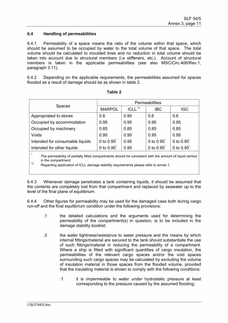
6.4 Handling of permeabilities 6.4.1 Permeability of a space means the ratio of the volume within that space, which should be assumed to be occupied by water to the total volume of that space. The total volume should be calculated to moulded lines and no reduction in total volume should be taken into account due to structural members (i.e stiffeners, etc.). Account of structural members is taken in the applicable permeabilities (see also MSC/Circ.406/Rev.1, paragraph 3.11). 6.4.2 Depending on the applicable requirements, the permeabilities assumed for spaces flooded as a result of damage should be as shown in table 2.
Table 2
Spaces Permeabilities
MARPOL ICLL 1) IBC IGC
Appropriated to stores 0.6 0.95 0.6 0.6
Occupied by accommodation 0.95 0.95 0.95 0.95
Occupied by machinery 0.85 0.85 0.85 0.85
Voids 0.95 0.95 0.95 0.95
Intended for consumable liquids 0 to 0.95* 0.95 0 to 0.95* 0 to 0.95*
Intended for other liquids 0 to 0.95* 0.95 0 to 0.95* 0 to 0.95*
* The permeability of partially filled compartments should be consistent with the amount of liquid carried in the compartment.
1) Regarding application of ICLL damage stability requirements please refer to annex 1.
6.4.3 Whenever damage penetrates a tank containing liquids, it should be assumed that the contents are completely lost from that compartment and replaced by seawater up to the level of the final plane of equilibrium. 6.4.4 Other figures for permeability may be used for the damaged case both during cargo run-off and the final equilibrium condition under the following provisions: .1 the detailed calculations and the arguments used for determining the
permeability of the compartment(s) in question, is to be included in the damage stability booklet;
.2 the water tightness/resistance to water pressure and the means by which
internal fittings/material are secured to the tank should substantiate the use of such fittings/material in reducing the permeability of a compartment. Where a ship is fitted with significant quantities of cargo insulation, the permeabilities of the relevant cargo spaces and/or the void spaces surrounding such cargo spaces may be calculated by excluding the volume of insulation material in those spaces from the flooded volume, provided that the insulating material is shown to comply with the following conditions:
.1 it is impermeable to water under hydrostatic pressure at least
corresponding to the pressure caused by the assumed flooding;
SLF 54/5 Annex 3, page 12
I:\SLF\54\5.doc
.2 it will not crush or break up due to hydrostatic pressure at least corresponding to the pressure caused by the assumed flooding;
.3 it will not deteriorate or change its properties over the long term in
the environment anticipated in the space it is installed;
.4 it is highly resistant to the action of hydrocarbons, where relevant; and
.5 it will be adequately secured so that it will remain in position if
subjected to collision damage and consequent displacement, distortion of its supporting and retaining structure, repeated rapid ingress and outflow of seawater and the buoyant forces caused by immersion following flooding;
.3 the applied permeability should reflect the general conditions of the ship
throughout its service life, rather than specific loading conditions; and .4 permeabilities, other than those indicated in table 2, should be considered
only in cases where it is evident that there is a significant discrepancy between the values shown in the regulations and the actual values (i.e. due to specific tank structure or insulating material).
6.5 Free-surface calculation (upright, as ship heels and after cargo run-off) With respect to the approval of actual loading conditions the following should be applied: 6.5.1 The free surfaces of liquids lead to the increase of the centre of gravity (KG) and the reduction of the metacentric height (GM) and the righting arm (GZ curve) of the ship. Therefore corrections should be made, taking into account the change of the centre of gravity of the ship due to the moving of the centre of gravity of the liquids. Depending on the filling level, free surfaces can exist in tanks with consumable liquids, seawater ballast and liquid cargo. 6.5.1.1 For consumable liquids account of the free surfaces should be taken whenever the filling level is equal to or less than 98 per cent. .1 In calculating the free surface effects in tanks containing consumable
liquids, it should be assumed that for each type of liquid at least one transverse pair or a single centreline tank has a free surface and the tank or combination of tanks taken into account should be those where the effect of free surfaces is the greatest.
.2 Taking into account .1, the free surfaces should correspond to the
maximum value attainable between the filling levels envisaged. 6.5.1.2 During ballasting between departure and arrival condition, the correction for the free surfaces should correspond to the maximum value attainable between the filling levels envisaged. This applies also for the situation where in the departure condition the filling level of a ballast tank is 0 per cent and in the arrival 100 per cent (or the opposite). 6.5.1.3 For the category of liquids referred under paragraphs 6.5.1.1 and 6.5.1.2, as an alternative intermediate loading conditions may be considered, as deemed necessary, covering the stage where the free surfaces are the greatest. It may be calculated with
SLF 54/5 Annex 3, page 13
I:\SLF\54\5.doc
varying free surface moments (i.e. actual liquid transfer moments), taking into account actual heel and trim, depending on the interval angles of the GZ curve. This is a more accurate method. 6.5.1.4 Except as indicated in 1988 LL/27(11)(v), for liquid cargo the effect of free surface should be taken into account for filling level equal or smaller to 98 per cent. If the filling level is fixed actual free surfaces can be applied. The following two methods can be used for the calculation of the GZ curve taking into account the effect of the free surface moments for the intact compartments: .1 Calculation with constant effect of free surfaces, without taking into account
the change in heel and trim, for the interval angles of the GZ curve.
.2 Calculation with varying free surface moments, actual liquid transfer moments, taking into account actual heel and trim, depending on the interval angles of the GZ curve (see annex 2).
6.5.2 For the damaged compartments, whenever the damage is involving cargo tanks, account should be taken of the following: .1 the impact on the stability of the ship due to the outflow of cargo and
ingress of seawater can be verified with the calculation of the intermediate stages of flooding (see section 9); and
.2 at the final equilibrium the free surface correction should exclude the free
surface moment of the lost cargo.
6.5.3 The free surface effect should be calculated at an angle of heel of 5 degrees for each individual compartment or as per paragraph 6.5.1.3. 6.6 Treatment of operational trim 6.6.1 For the assumed damage and the resultant damage cases, the damage stability should be assessed for all anticipated conditions of loading and variations in draught and trim. 6.6.2 Significant trim values (greater than 1% Lpp) can appear in the aft/fore part of the ship in the departure and arrival condition. In that case, damage cases involving the aft/fore part of the ship might be critical for achieving compliance with the applicable criteria. In order to limit the trim ballast water is used during the voyage, as deemed necessary. Under the provision of paragraphs 6.5.1.2 and 6.5.1.3, for taking account of the free surface effect during ballasting, if intermediate stages of the voyage are considered then the loading conditions representing these stages, should be also calculated for damage stability. 6.7 Downflooding points 6.7.1 Downflooding point is the lower edge of any opening through which progressive flooding may take place. Such openings should include air-pipes, ventilators and those which are closed by means of weathertight doors or hatch covers and may exclude those openings closed by means of watertight manhole covers and flush scuttles, small watertight cargo tank hatch covers which maintain the high integrity of the deck, remotely operated watertight sliding doors, and sidescuttles of non-opening type.
SLF 54/5 Annex 3, page 14
I:\SLF\54\5.doc
6.7.2 All openings through which progressive flooding may take place should be defined: both weathertight and unprotected. As an alternative it might be accepted to consider only the most critical openings, which are considered to be the openings with the lowest vertical position and close to the side shell. Concerning the longitudinal position it depends on the aft or fore trim of the initial condition and the trim after damage at equilibrium. Unprotected openings should not be immersed within the minimum range of righting-lever curve required for the ship. Within this range, the immersion of any of openings capable of being closed weathertight may be permitted. 6.8 Cross-flooding time 6.8.1 Cross-flooding time should be calculated in accordance with the Recommendation on a standard method for evaluating cross-flooding arrangements (resolution MSC.245(83)). 6.8.2 If complete fluid equalization occurs in 60 s or less, the equalized tank should be assumed flooded with the tanks initially to be flooded and no further calculations need to be carried out. Otherwise, the flooding of tanks assumed to be initially damaged and equalized tank should be carried out in accordance with paragraph 9.2. Only passive open cross-flooding arrangements without valves should be considered for instantaneous cases. 6.8.3 Where cross-flooding devices are fitted, the safety of the ship should be demonstrated in all stages of flooding (see paragraph 9.2 and section 10). Cross-flooding equipment, if installed, should have the capacity to ensure that the equalization takes place within 10 min. 6.8.4 Tanks and compartments taking part in such equalization should be fitted with air pipes or equivalent means of sufficient cross-section to ensure that the flow of water into the equalization compartments is not delayed. 6.8.5 Spaces which are linked by ducts of a large cross-sectional area may be considered to be common, i.e. the flooding of these spaces should be interpreted as instantaneous flooding with the equalization of duration of less than 60 s. 6.9 Progressive flooding (internal/external) (see also paragraphs 10.1 and 10.2) 6.9.1 Progressive flooding is the flooding of compartments situated outside of the assumed extent of damage. Progressive flooding may extend to compartments, other than those assumed flooded, through downflooding points (i.e. unprotected and weathertight openings), pipes, ducts, tunnels, etc. 6.9.2 The flooding of compartment(s) due to progressive flooding occurring in a predictable and sequential manner through a downflooding point which is submerged below the damage waterline may be permitted provided all intermediate stages and the final stage of flooding meet the required stability criteria. 6.9.3 Minor progressive flooding through the pipes situated within the assumed extent of damage may be permitted by the Administration, provided the pipes penetrating a watertight subdivision have a total cross-sectional area of not more than 710 mm2 between any two watertight compartments. 6.9.4 If the opening (unprotected or fitted with a weathertight means of closure) connects two spaces, this opening should not be taken into account if the two connected spaces are flooded or none of these spaces are flooded. If the opening is connected to the outside, it should not be taken into account only if the connected compartment is flooded.
SLF 54/5 Annex 3, page 15
I:\SLF\54\5.doc
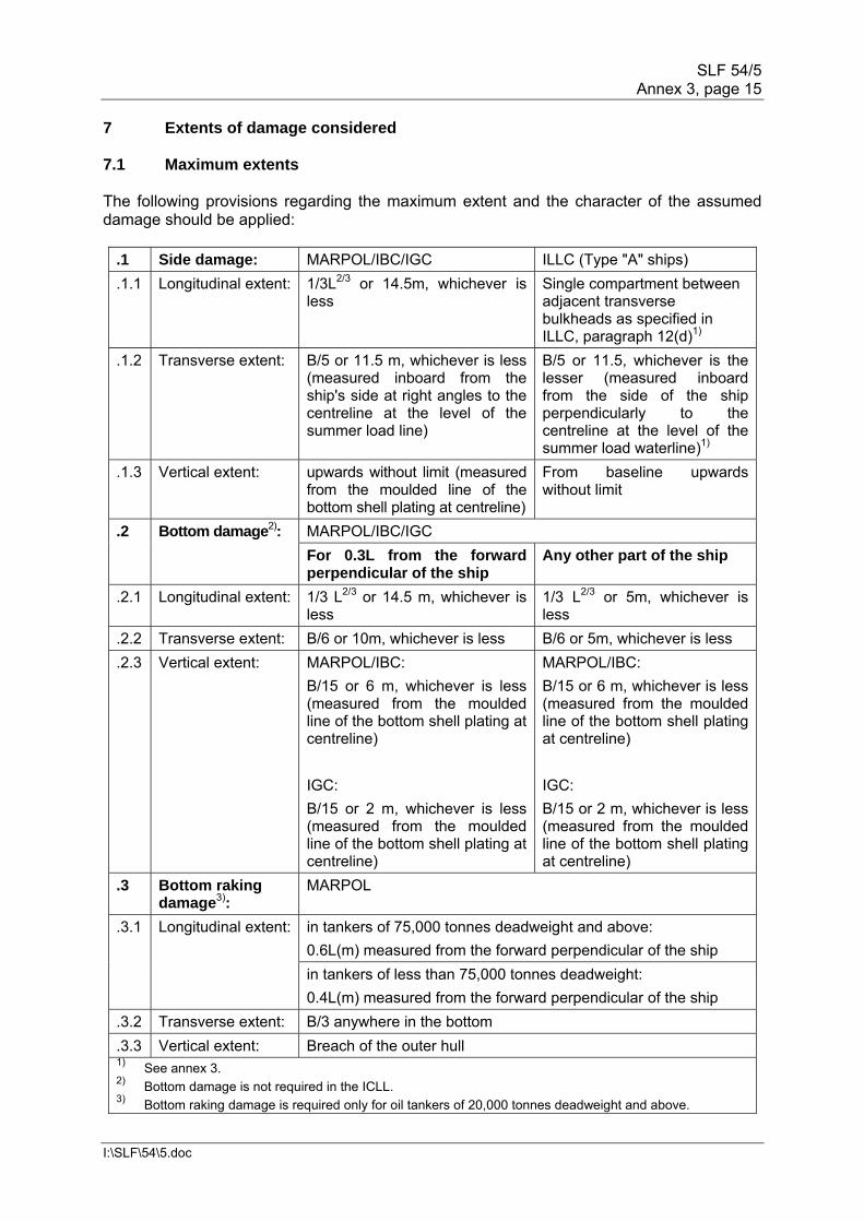
7 Extents of damage considered 7.1 Maximum extents The following provisions regarding the maximum extent and the character of the assumed damage should be applied:
.1 Side damage: MARPOL/IBC/IGC ILLC (Type "A" ships)
.1.1 Longitudinal extent: 1/3L2/3 or 14.5m, whichever is less
Single compartment between adjacent transverse bulkheads as specified in ILLC, paragraph 12(d)1)
.1.2 Transverse extent: B/5 or 11.5 m, whichever is less (measured inboard from the ship's side at right angles to the centreline at the level of the summer load line)
B/5 or 11.5, whichever is the lesser (measured inboard from the side of the ship perpendicularly to the centreline at the level of the summer load waterline)1)
.1.3 Vertical extent: upwards without limit (measured from the moulded line of the bottom shell plating at centreline)
From baseline upwards without limit
.2 Bottom damage2): MARPOL/IBC/IGC
For 0.3L from the forward perpendicular of the ship
Any other part of the ship
.2.1 Longitudinal extent: 1/3 L2/3 or 14.5 m, whichever is less
1/3 L2/3 or 5m, whichever is less
.2.2 Transverse extent: B/6 or 10m, whichever is less B/6 or 5m, whichever is less
.2.3 Vertical extent: MARPOL/IBC:
B/15 or 6 m, whichever is less (measured from the moulded line of the bottom shell plating at centreline)
IGC:
B/15 or 2 m, whichever is less (measured from the moulded line of the bottom shell plating at centreline)
MARPOL/IBC:
B/15 or 6 m, whichever is less (measured from the moulded line of the bottom shell plating at centreline)
IGC:
B/15 or 2 m, whichever is less (measured from the moulded line of the bottom shell plating at centreline)
.3 Bottom raking damage3):
MARPOL
.3.1 Longitudinal extent: in tankers of 75,000 tonnes deadweight and above:
0.6L(m) measured from the forward perpendicular of the ship
in tankers of less than 75,000 tonnes deadweight:
0.4L(m) measured from the forward perpendicular of the ship
.3.2 Transverse extent: B/3 anywhere in the bottom
.3.3 Vertical extent: Breach of the outer hull 1) See annex 3. 2) Bottom damage is not required in the ICLL. 3) Bottom raking damage is required only for oil tankers of 20,000 tonnes deadweight and above.

SLF 54/5 Annex 3, page 16
I:\SLF\54\5.doc
7.2 Lesser extents 7.2.1 If any damage of a lesser extent than the maximum damage specified in 7.1 would result in a more severe condition, such damage should be considered (see paragraph 4.5). 7.2.2 In the case of a gas carrier, local side damage anywhere in the cargo area extending inboard 760 mm measured normal to the hull shell should be considered and transverse bulkheads should be assumed damaged when also required by the applicable subparagraphs of 2.8.1 of the IGC Code. 7.3 Rationale for reviewing lesser extents including symmetrical vs. unsymmetrical
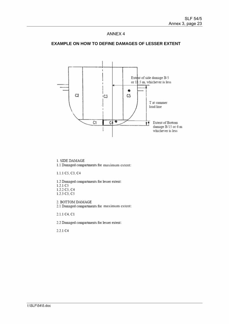
tank arrangement/geometry – Calculation on weakest side 7.3.1 For a given loading condition, following examples of damages of lesser extent may result in a more severe situation than that caused by a maximum damage specified in 7.1: .1 Example of damage on double bottom tanks with watertight centre girder:
.1 Damage of lesser extent which could occur at the bottom plate of the ship, without damaging the centre girder, will lead to flooding of the double bottom tank on one side of the ship only. This is the case of unsymmetrical flooding. For the same location, damage of maximum extent would cause damage on the centre girder and therefore flooding of the double bottom tanks on both sides. This is the case of symmetrical flooding (see annex 4).
.2 Compared to the symmetrical flooding in the case of maximum
damage extent, unsymmetrical flooding of spaces, caused by damage of lesser extent might lead to a more severe situation. Of course, in case of non-watertight centre girder, the effect of damage of lesser and maximum extent would be the same.
.2 Example of damage with lesser vertical extents:
Damage starting from above a tank top would flood the spaces only above the double bottom (see annex 4). This may result in a more onerous residual stability or heeling angle.
7.3.2 Taking into account the above examples, it is necessary to review damages of lesser extents considering the symmetrical or unsymmetrical nature of tank arrangements of the ship and geometry of the ship. The ship's damage stability is to be ensured, in the most severe or weakest case of damage of lesser extents. 8 Rationale applied for loading pattern evaluation For damage stability calculations of tank ships the following effects due to different loading methods should be taken into account in determining the scope of verification and specific cases of damage to be investigated. 8.1 Homogeneous vs. alternate/partial loading 8.1.1 For homogeneous loading conditions the damage of cargo tanks may have a major effect on residual stability. Outflow of the loaded cargo liquids (and less inflow of seawater) may reduce the ships displacement and cause heel to opposite side of the damage.
SLF 54/5 Annex 3, page 17
I:\SLF\54\5.doc
For alternate loading conditions, the residual stability depends on the damaged cargo tank. Damage to a fully-loaded cargo tank might cause reduction of the initial displacement and heel to the opposite side, but damage to an empty cargo tank might cause the opposite effect. For the damage to two adjacent cargo tanks, one filled and one empty, the total effect might be less severe due to two (partly) neutralizing effects. 8.1.2 Partial loading of liquid cargo tanks will cause a high free surface moment when the surface does not intersect with the tank overhead and will increase the heel in case of damage. However, reductions of the initial displacement and heel to the opposite side may not be as significant. Trim to the ship as a consequence of damage can be significant due to many partially filled cargo tanks. 8.2 Symmetrical and unsymmetrical loading pattern In general, damage stability calculations should be performed for both ship sides. However, the damage stability calculation for one side of the ship may be accepted for symmetrical load (alternate, homogeneous, full, partial or empty), if the ship and all openings are also symmetrical and initial heel to portside or starboard is zero. 8.3 MSC/Circ.406/Rev.1 Additional information regarding intact and damage stability matters for tank ships can be found in MSC/Circ.406/Rev.1 which also recommends application of the "Guidelines for the Uniform Application of the Survival Requirements of the Bulk Chemical Code (BCH Code) and the Gas Carrier Code (GC Code)" to the IBC and IGC Codes. 9 Intermediate stages of flooding including equalization, if any, and cargo
run-off Intermediate stages of flooding cover the flooding process from the commencement of flooding up to but excluding the final equilibrium damage condition (see also paragraph 3.4.3.2). Intermediate stages should be comprehensively checked for all ships at the design appraisal stage. 9.1 Basis for checking intermediate stages of flooding and minimum stability
criteria applied The stability criteria applicable to the final equilibrium stage should also be satisfied for all intermediate stages. If any stability criteria during intermediate stages showa more severe values than in the final stage of flooding, this intermediate stage should also be submitted. 9.2 Number of intermediate stages considered 9.2.1 A sufficient number of intermediate stages should be examined for all damage cases. It is generally recommended to apply five intermediate stages of flooding (see also paragraphs 6.8, 6.9 and 10.1). 9.2.2 If the ship is equipped with non-instantaneous (greater than 60 s) passive equalization arrangements or non-passive equalization arrangements of any size the following procedure is to be used: .1 compliance with the relevant criteria should be demonstrated without using
equalization arrangements for intermediate and final stages; and
SLF 54/5 Annex 3, page 18
I:\SLF\54\5.doc
.2 for subsequent equalization additional two intermediate stages and final stages the compliance should also be demonstrated.
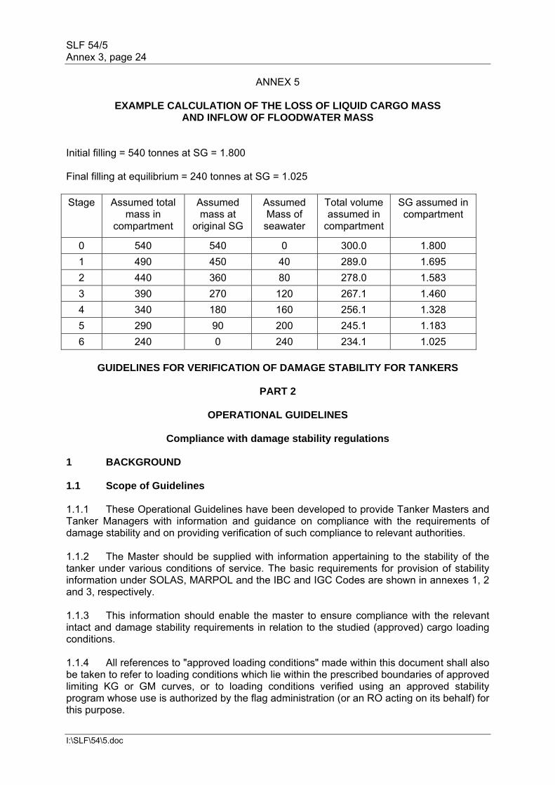
9.3 Cargo outflow and flood water inflow 9.3.1 During intermediate flooding stages, a practical method of calculating the floating position and residual righting moments is the added weight method where the intact condition is corrected for the weights of inflowing floodwater and outflowing cargo. 9.3.2 During each stage an assumed amount of added floodwater and/or cargo outflow should be used. The following method is recommended: .1 for a loaded tank an equal loss of liquid cargo mass and equal inflow of
floodwater mass at each stage resulting in a total loss of liquid cargo at and total inflow of floodwater to the final damage equilibrium waterline; and
.2 for an empty tank an equal inflow of floodwater mass at each stage
resulting in total inflow of floodwater to the final damage equilibrium waterline.
See annex 5 for example calculation. [9.3.3 Alternative methods may be accepted, for example: .1 For a loaded tank the loss of liquid cargo mass and inflow of floodwater mass
is based on a linear change of total tank content density over each intermediate stage from pure cargo at the intact condition to pure floodwater at the final damage equilibrium waterline.
.2 For an empty tank an increasing depth of water at each stage based on the
difference between the depth of water in the tank and the depth to the waterline in way of the tank, divided by the number of remaining stages, resulting in total inflow of floodwater to the final damage equilibrium waterline.]
9.3.4 Noting that calculation of stability in the final damage condition assumes both the liquid cargo and the buoyancy of the damaged spaces to be lost, it is therefore considered both reasonable and consistent to base the residual GZ curve at each intermediate stage on the intact displacement minus total liquid cargo loss at each stage. 9.4 Treatment of free surface and KG adjustment 9.4.1 Taking due account of the requirements of paragraph 6.5.1.1, it is generally recommended to apply actual liquid transfer moments for all tank filling levels in determining compliance with the relevant damage stability criteria through direct calculations of actual loading conditions. 9.4.2 With regard to the treatment of free surfaces of flooded spaces and noting that there will be combinations of empty and loaded tanks within the damaged extent all damaged compartments should be considered individually flooded during the intermediate stages – i.e. individual free surfaces. (The compartments are considered open to the sea in the final damage condition.)
SLF 54/5 Annex 3, page 19
I:\SLF\54\5.doc
10 Final stage of flooding (Resolution MSC.281(85) to be referred to) 10.1 Watertight and weathertight integrity 10.1.1 The mandatory instruments referenced in paragraph 2.1 require the final waterline, taking into account sinkage, heel and trim, shall be below the lower edge of any opening through which progressive flooding may take place. Such openings shall include air-pipes (irrespective of closing devices) and those which are closed by means of weathertight doors or hatch covers and may exclude those openings closed by means of watertight manhole covers and flush scuttles, small watertight cargo tank hatch covers which maintain the high integrity of the deck, remotely operated watertight sliding doors, and sidescuttles of the non-opening type. 10.1.2 Within the required range of residual stability, the immersion of any of the openings listed above and other openings capable of being closed weathertight may be permitted. 10.1.3 In the final equilibrium condition watertight escape hatches should not be submerged below the equilibrium damage waterline and should be treated as weathertight openings4. 10.1.4 For the emergency generator room the lowest point of the room should remain above the final equilibrium damage waterline. Any opening leading to this room should be treated as unprotected or weathertight, as applicable. 10.1.5 The following principles apply: .1 Watertight doors under the final waterline after flooding All watertight doors under the final waterline after flooding should be
remotely operated sliding watertight doors. Installation of a hinged watertight door (e.g. between the steering gear compartment and engine-room) is subject to acceptance by the Administration.
.2 Progressive flooding due to damage or submersion of air pipes Progressive flooding may be accepted subject to the air pipes leading to
relatively small compartments which are progressively flooded in a predictable and sequential manner in which all intermediate stages of flooding (with the exception of no progressive flooding) and the final stage of flooding meet the required stability criteria.
.3 Watertight doors on the aft wall of forecastle under the final waterline after
flooding.
4 This specification applies only to the escapes from spaces other than tanks.
SLF 54/5 Annex 3, page 20
I:\SLF\54\5.doc
10.1.6 Hinged watertight doors at the aft bulkhead of a forecastle space are permitted to be submerged after damage only when possible progressive flooding is limited to one relatively small compartment which is progressively flooded in a predictable and sequential manner in which all intermediate stages of flooding (with the exception of no progressive flooding) and the final stage of flooding meet the required stability criteria. No further progressive flooding is permitted beyond the initial flooding of the forecastle. This approach is only permitted after all other options, such as increasing the sill height, relocating the door, only providing access from above, have been shown to be unworkable in practice. 10.2 Unprotected openings Residual GZ curves should be terminated at the lowest angle of submersion of an unprotected opening.
ANNEX 1
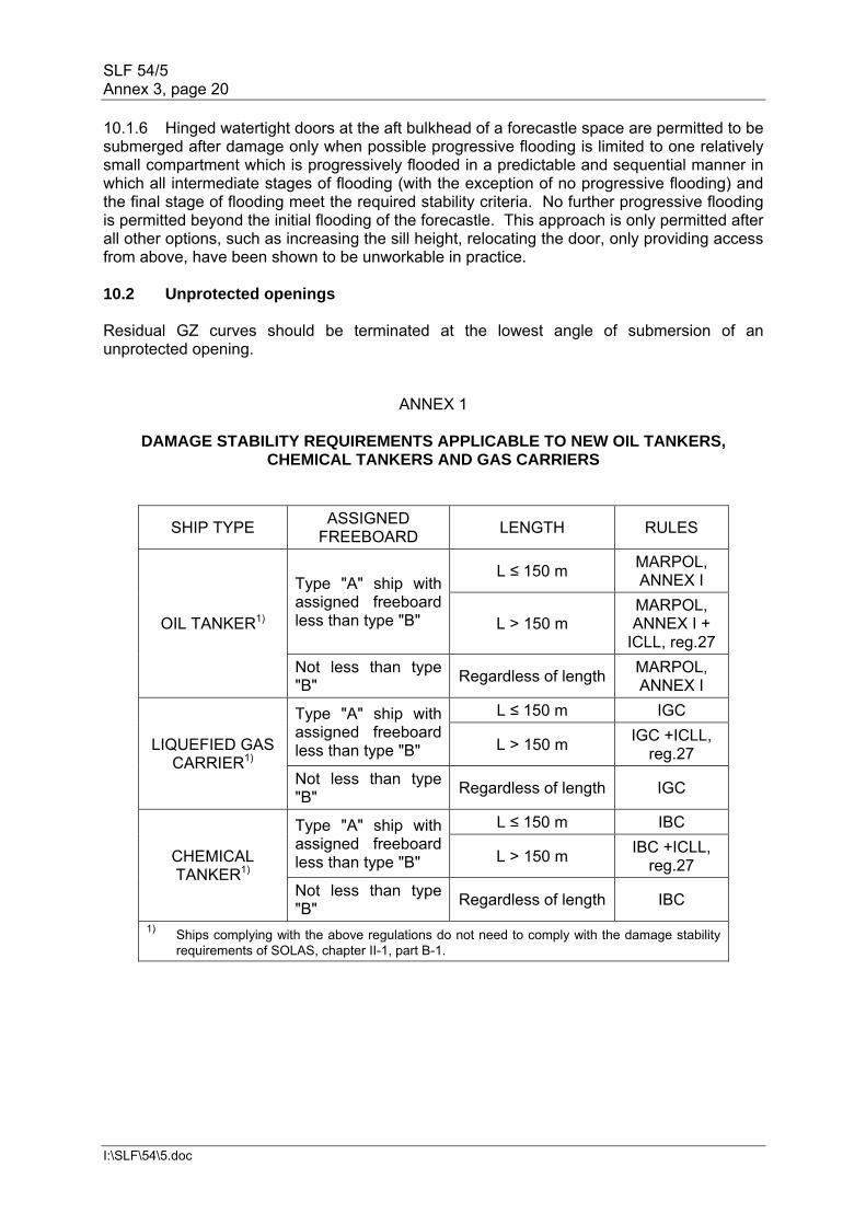
DAMAGE STABILITY REQUIREMENTS APPLICABLE TO NEW OIL TANKERS, CHEMICAL TANKERS AND GAS CARRIERS
SHIP TYPE ASSIGNED
FREEBOARD LENGTH RULES
OIL TANKER1)
Type "A" ship with assigned freeboard less than type "B"
L ≤ 150 m MARPOL, ANNEX I
L > 150 m MARPOL, ANNEX I +
ICLL, reg.27
Not less than type "B"
Regardless of lengthMARPOL, ANNEX I
LIQUEFIED GAS CARRIER1)
Type "A" ship with assigned freeboard less than type "B"
L ≤ 150 m IGC
L > 150 m IGC +ICLL,
reg.27
Not less than type "B"
Regardless of length IGC
CHEMICAL TANKER1)
Type "A" ship with assigned freeboard less than type "B"
L ≤ 150 m IBC
L > 150 m IBC +ICLL,
reg.27
Not less than type "B"
Regardless of length IBC
1) Ships complying with the above regulations do not need to comply with the damage stability requirements of SOLAS, chapter II-1, part B-1.
SLF 54/5 Annex 3, page 21
I:\SLF\54\5.doc
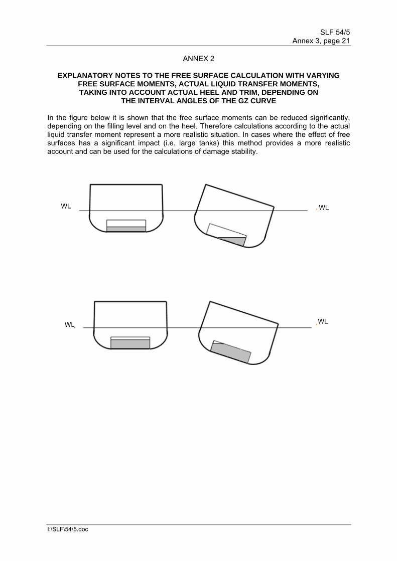
ANNEX 2
EXPLANATORY NOTES TO THE FREE SURFACE CALCULATION WITH VARYING FREE SURFACE MOMENTS, ACTUAL LIQUID TRANSFER MOMENTS, TAKING INTO ACCOUNT ACTUAL HEEL AND TRIM, DEPENDING ON
THE INTERVAL ANGLES OF THE GZ CURVE In the figure below it is shown that the free surface moments can be reduced significantly, depending on the filling level and on the heel. Therefore calculations according to the actual liquid transfer moment represent a more realistic situation. In cases where the effect of free surfaces has a significant impact (i.e. large tanks) this method provides a more realistic account and can be used for the calculations of damage stability.
WL WL
WL WL
SLF 54/5 Annex 3, page 22
I:\SLF\54\5.doc
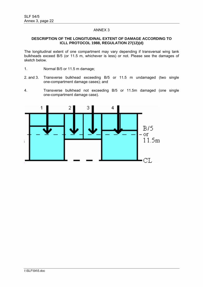
ANNEX 3
DESCRIPTION OF THE LONGITUDINAL EXTENT OF DAMAGE ACCORDING TO ICLL PROTOCOL 1988, REGULATION 27(12)(d)
The longitudinal extent of one compartment may vary depending if transversal wing tank bulkheads exceed B/5 (or 11.5 m, whichever is less) or not. Please see the damages of sketch below. 1. Normal B/5 or 11.5 m damage; 2. and 3. Transverse bulkhead exceeding B/5 or 11.5 m undamaged (two single
one-compartment damage cases); and 4. Transverse bulkhead not exceeding B/5 or 11.5m damaged (one single
one-compartment damage case).
SLF 54/5 Annex 3, page 23
I:\SLF\54\5.doc
ANNEX 4
EXAMPLE ON HOW TO DEFINE DAMAGES OF LESSER EXTENT
SLF 54/5 Annex 3, page 24
I:\SLF\54\5.doc
ANNEX 5
EXAMPLE CALCULATION OF THE LOSS OF LIQUID CARGO MASS AND INFLOW OF FLOODWATER MASS
Initial filling = 540 tonnes at SG = 1.800 Final filling at equilibrium = 240 tonnes at SG = 1.025 Stage Assumed total
mass in compartment
Assumed mass at
original SG
Assumed Mass of
seawater
Total volume assumed in
compartment
SG assumed in compartment
0 540 540 0 300.0 1.800
1 490 450 40 289.0 1.695
2 440 360 80 278.0 1.583
3 390 270 120 267.1 1.460
4 340 180 160 256.1 1.328
5 290 90 200 245.1 1.183
6 240 0 240 234.1 1.025
GUIDELINES FOR VERIFICATION OF DAMAGE STABILITY FOR TANKERS
PART 2
OPERATIONAL GUIDELINES
Compliance with damage stability regulations 1 BACKGROUND 1.1 Scope of Guidelines 1.1.1 These Operational Guidelines have been developed to provide Tanker Masters and Tanker Managers with information and guidance on compliance with the requirements of damage stability and on providing verification of such compliance to relevant authorities. 1.1.2 The Master should be supplied with information appertaining to the stability of the tanker under various conditions of service. The basic requirements for provision of stability information under SOLAS, MARPOL and the IBC and IGC Codes are shown in annexes 1, 2 and 3, respectively. 1.1.3 This information should enable the master to ensure compliance with the relevant intact and damage stability requirements in relation to the studied (approved) cargo loading conditions. 1.1.4 All references to "approved loading conditions" made within this document shall also be taken to refer to loading conditions which lie within the prescribed boundaries of approved limiting KG or GM curves, or to loading conditions verified using an approved stability program whose use is authorized by the flag administration (or an RO acting on its behalf) for this purpose.
SLF 54/5 Annex 3, page 25
I:\SLF\54\5.doc
1.1.5 In the case where curves of minimum operational GM or maximum operational KG are included in stability information, the ability to verify intact and damage stability compliance for other conditions of loading should also be ensured. 1.1.6 However, the provision of limiting operational GM or KG data is not always practicable for tankers and such data may not be provided. In this case the advice at SOLAS chapter II-1, regulation 5-1(5) applies. 1.1.7 Considerations on the scope and type of stability information are given in part 3 of annex 4. 1.2 Introduction 1.2.1 Responsibility 1.2.1.1 It is required under MARPOL and SOLAS to ensure that the ship is loaded in accordance with all relevant stability criteria, prior to proceeding to sea. This responsibility is identified in the relevant provisions of SOLAS and MARPOL. There are additional provisions and requirements for certificates issued under the IBC and IGC Codes. 1.2.1.2 In order to understand this issue the terms Intact Stability, Damage stability and Stability in the damaged condition should be understood and are explained below. 1.2.2 Compliance with intact stability 1.2.2.1 The International Code on Intact Stability* provides information and criteria which must be complied with by cargo and passenger ships. This Intact Stability information is provided to the master as per SOLAS chapter II-1, regulation 5-1. 1.2.2.2 During normal operations the intact stability of a ship is assessed by either using an intact stability function attached to a loading or stability instrument or by manual calculations. 1.2.2.3 Compliance with intact stability shall be demonstrated before proceeding to sea and evidence of this documented. 1.2.3 Compliance with damage stability 1.2.3.1 Damage stability requirements in SOLAS, chapter II-1, parts B-1 to B-4, must be complied with by all cargo ships above 80 m length other than those which are required to comply with subdivision and damage stability regulations in other IMO instruments. 1.2.3.2 In the case of oil tankers, chemical tankers and gas carriers the damage stability provisions of MARPOL Annex I, the International Code for the Construction and Equipment of Ships Carrying Dangerous Chemicals in Bulk (IBC Code) and the International Code for the Construction and Equipment of Ships Carrying Liquefied Gases in Bulk (IGC Code), apply respectively in place of the damage stability requirements of SOLAS chapter II-1, parts B-1 to B-4.
SLF 54/5 Annex 3, page 26
I:\SLF\54\5.doc
1.2.3.3 Information provided to the Minister in the form of a stability booklet contains loading conditions (including ballast conditions) which have been verified to ensure compliance with both intact and damage stability requirements relative to its ship type. When the tanker is in an operational condition which is not covered by one of the loading conditions contained in the stability booklet then compliance with damage stability must be verified prior to proceeding to sea and evidence of this documented. ______________
* Refer to the International Code on Intact Stability, 2008 (2008 IS Code), adopted by resolution MSC.267(85).
1.2.4 The Stability of the ship in the damaged condition 1.2.4.1 This is the residual stability of the ship after an actual damage to its structure, and consequent flooding, has occurred. Damages of varying size and layout are evaluated during approval of stability information, up to the damage of maximum extent as defined within the regulations which apply to a particular ship. 1.2.4.2 Compliance with basic intact stability criteria does not necessarily ensure compliance with damage stability requirements and intact stability characteristics well in excess of the statutory minimum may be necessary for a particular loading condition to ensure compliance with damage stability. 1.2.4.3 Compliance with damage stability requirements should always be verified prior to sailing, and is required to ensure a ship shall survive a damage of any extent up to the maximum extent required by the Regulations which apply to it, should such a damage occur. Use of a shore-side contractor, retained to provide emergency evaluation and assistance in the event that a damage does occur in service, is not an accepted means to make such pre-departure verification. 1.2.4.4 It is important to note that in the event of ANY damage occurring to the ship which requires reporting to the flag Administration, Port State and Classification Society, specialist advice should always be sought to verify the continued structural integrity. 2 COMPLIANCE It is the responsibility of the master to ensure the ship is loaded in accordance with the applicable intact and damaged stability criteria during all operational cargo conditions. The master may also be required to demonstrate compliance with these stability criteria to different surveying and inspecting authorities. Regulations governing damage stability requirements are contained in various instruments developed by the IMO (refer to part 4 of annex 4 for further detail). 2.1 Compliance with regulations The master will need to be provided with sufficient information to demonstrate their ship is loaded in a manner which will ensure compliance with the relevant Regulations which apply to its type, size and age. Information to be provided should include: .1 Load Lines information; .2 shear force and bending moments information; .3 draft information;
SLF 54/5 Annex 3, page 27
I:\SLF\54\5.doc
.4 intact stability information; and .5 damage stability information. 3 METHODS TO DEMONSTRATE VERIFICATION OF COMPLIANCE There are various methods available to the master which can be used to demonstrate compliance with the Regulations, as follows: .1 to load the ship only in accordance with the approved loading conditions as
given in the approved Stability Information Booklet (refer to parts 1 and 2 of annex 4); or
.2 where the ship is not loaded in accordance with an approved loading
condition from the approved Stability Information Booklet, obtain approval from the Administration or recognized organization (RO) acting on its behalf for the proposed loading condition. It is recommended in this case that the accuracy of the verified loading condition is validated by cross-checking the predicted floating position with the observed condition viewed from the quay; or
.3 where the ship is not loaded in accordance with an approved loading
condition from the approved Stability Information Booklet, when authorized by the Administration (or RO acting on its behalf) obtain confirmation from the shore-based operating company that the proposed loading condition complies. It is recommended in this case that the accuracy of the verified loading condition is validated by cross-checking the predicted floating position with the observed condition viewed from the quay; or
.4 to use an approved stability program (stability instrument) or other
acceptable method to verify that intact stability and damage stability criteria are satisfied for this operating condition. When an approved stability program is used for such verification then use of this program must be specified in the ship's approved Stability Information Booklet or on the ship's certificate of fitness. Approved stability programs may be approved as IACS URL5 damage stability software of Type 2 or Type 3; or
.5 the use of simplified stability data, for example curves of maximum KG or
minimum allowable GM, to demonstrate compliance, noting that where such simplified data are used it is necessary to ensure that any restrictions applied in their development are also fulfilled in the actual loading condition being assessed. Use of simplified intact stability data for this purpose is not sufficient and verification must also be made against approved damage stability data. In the case of parcel tankers it is recommended that such checks are made using an approved Type 2 stability program as provided for in the 2008 IS Code, part B, Chapter 4.
4 WHEN COMPLIANCE IS NOT INITIALLY DEMONSTRATED The master should not sail until the ship is in full compliance with all stability requirements. In a situation where it has not been possible to demonstrate compliance by any of the previously mentioned methods, there are a number of choices available, as follows:
SLF 54/5 Annex 3, page 28
I:\SLF\54\5.doc
.1 to adjust the loading of the ship so that it complies with an approved condition from the ship's approved Stability Information Booklet (refer to parts 1 and 2 of annex 4); or
.2 to adjust the loading of the ship until the loading computer intact and
damage stability modules show that compliance has been achieved, whilst ensuring that all other requirements of the voyage such as load line and strength requirements are met; or
.3 to contact shore-based operating company when authorized by the
Administration (or RO acting on its behalf) and request assistance in the calculation of the intact and damage stability for an adjusted loading condition to ensure compliance with the Regulations. It is recommended in this case that the accuracy of the verified loading condition is validated by cross-checking the predicted floating position with the observed condition viewed from the quay; or
.4 to contact the RO acting on behalf of the Administration and request
assistance in the calculation of the intact and damage stability for an adjusted loading condition to ensure compliance with the Regulations. It is recommended in this case that the accuracy of the verified loading condition is validated by cross-checking the predicted floating position with the observed condition viewed from the quay.
5 DOCUMENTATION 5.1 All checks and diligence carried out in ensuring that the ship is in compliance with the regulations should be documented in accordance with the company's operating procedures and the company's safety management system. 5.2 It is important that any manual calculations done to ensure compliance or printouts from an approved Loading Computer used for this purpose should be kept on file to maintain an audit trail and to be able to demonstrate compliance to company auditors, surveyors, port State control inspectors, etc. _______________
* There are three types of Approved Stability Programs/Software, details of which are provided in IACS Unified Requirement No.5 for Load Lines (UR L5) and the 2008 IS Code, Chapter 4. A brief description of the three types is as follows. Three types of calculations performed by stability software are acceptable depending upon a ship's stability requirements:
Type 1: software calculating intact stability only (for ships not required to meet a
damage stability criterion); Type 2: software calculating intact stability and checking damage stability on basis
of a limit curve (e.g. for ships applicable to SOLAS, part B-1, damage stability calculations, etc.) or previously approved loading conditions; and
Type 3: software calculating intact stability and damage stability by direct
application of pre-programmed damage cases for each loading condition (for some tankers, etc.).

SLF 54/5 Annex 3, page 29
I:\SLF\54\5.doc
ANNEX 1
SOLAS REQUIREMENTS FOR PROVISION OF STABILITY INFORMATION INCLUDING DAMAGE STABILITY INFORMATION
(Based on SOLAS 2009 Consolidated Edition)
"Part B-1 Stability"
Regulation 5-1 – Stability information to be supplied to the master 1 The master shall be supplied with such information satisfactory to the Administration as is necessary to enable him by rapid and simple processes to obtain accurate guidance as to the stability of the ship under varying conditions of service. A copy of the stability information shall be furnished to the Administration. 2 The information should include:
.1 curves or tables of minimum operational metacentric height (GM) versus draught which assures compliance with the relevant intact and damage stability requirements, alternatively corresponding curves or tables of the maximum allowable vertical centre of gravity (KG) versus draught, or with the equivalents of either of these curves;
.2 instructions concerning the operation of cross-flooding arrangements; and
.3 all other data and aids which might be necessary to maintain the required
intact stability and stability after damage. 3 The stability information shall show the influence of various trims in cases where the operational trim range exceeds ± 0.5% of Ls. 4 For ships which have to fulfil the stability requirements of part B-1, information referred to in paragraph 2 are determined from considerations related to the subdivision index, in the following manner: Minimum required GM (or maximum permissible vertical position of centre of gravity KG) for the three draughts ds, dp and dl are equal to the GM (or KG values) of corresponding loading cases used for the calculation of survival factor si. For intermediate draughts, values to be used shall be obtained by linear interpolation applied to the GM value only between the deepest subdivision draught and the partial subdivision draught and between the partial load line and the light service draught respectively. Intact stability criteria will also be taken into account by retaining for each draught the maximum among minimum required GM values or the minimum of maximum permissible KG values for both criteria. If the subdivision index is calculated for different trims, several required GM curves will be established in the same way. 5 When curves or tables of minimum operational metacentric height (GM) versus draught are not appropriate, the master should ensure that the operating condition does not deviate from a studied loading condition, or verify by calculation that the stability criteria are satisfied for this loading condition.
SLF 54/5 Annex 3, page 30
I:\SLF\54\5.doc
ANNEX 2
REQUIREMENTS FOR DAMAGE STABILITY INFORMATION
MARPOL Annex I, regulation 28 "5 The master of every oil tanker to which this regulation applies and the person in charge of a non-self-propelled oil tanker to which this regulation applies shall be supplied in an approved form with:
.1 information relative to loading and distribution of cargo necessary to ensure compliance with the provisions of this regulation; and
.2 data on the ability of the ship to comply with damage stability criteria as
determined by this regulation, including the effect of relaxations that may have been allowed under subparagraph 1.3 of this regulation."
ANNEX 3
INFORMATION ON STABILITY TO BE PROVIDED UNDER RELEVANT CLAUSES OF THE IBC AND IGC CODES
The extracts below are provided for guidance only. Reference should be made to chapter 2 in each of the particular Codes. Particular attention is to be given to the certificate requirements listed at the end of this annex. IGC Code, clause 2.2.5: The master of the ship should be supplied with a loading and stability Information booklet. This booklet should contain details of typical service and ballast conditions, loading, unloading and ballasting operations, provisions for evaluating other conditions of loading and a summary of the ship's survival capabilities. In addition, the booklet should contain sufficient information to enable the master to load and operate the ship in a safe and seaworthy manner. IGC Code, clause 2.4: Damage survival capability should be investigated on the basis of loading information submitted to the Administration for all anticipated conditions of loading and variations in draught and trim. The survival requirements need not be applied to the ship when in the ballast condition, provided that any cargo retained on board is solely used for cooling, circulation or fuelling purposes. (NB: this clause should be read in conjunction with the certificate requirements below.) IBC Code, clause 2.2.5: The master of the ship shall be supplied with a loading and stability Information booklet. This booklet shall contain details of typical service and ballast conditions, provisions for evaluating other conditions of loading and a summary of the ship's survival capabilities. In
SLF 54/5 Annex 3, page 31
I:\SLF\54\5.doc
addition, the booklet shall contain sufficient information to enable the master to load and operate the ship in a safe and seaworthy manner. IBC Code, clause 2.4: Damage survival capability shall be investigated on the basis of loading information submitted to the Administration for all anticipated conditions of loading and variations in draught and trim. Ballast conditions where the chemical tanker is not carrying products covered by the Code, or is carrying only residues of such products, need not be considered. (NB: this clause should be read in conjunction with the certificate requirements below.) Requirements on the Certificates of Fitness for the IBC and IGC Codes The Certificates of Fitness issued under both of these Codes contain the following clauses: That the ship must be loaded: .1 in accordance with the loading conditions provided in the approved loading
manual, stamped and dated ............................ and signed by a responsible officer of the Administration, or of an organization recognized by the Administration;
.2 in accordance with the loading limitations appended to this Certificate. Where it is required to load the ship other than in accordance with the above instruction, then the necessary calculations to justify the proposed loading conditions shall be communicated to the certifying Administration who may authorize in writing the adoption of the proposed loading condition.
ANNEX 4
DEFINITIONS AND INTERPRETATIONS
Part 1 – Approved Loading Condition .1 In relation to a tanker certified under MARPOL Annex I or the IBC and
IGC Codes, an approved loading condition is a unique individual condition of loading, taking account of the combination of lightship and all individual deadweight items, which has been verified by the flag State (or recognized organization acting on its behalf) as complying with both intact and damaged stability criteria and is approved for use in service of the ship.
.2 The approval of an individual loading condition is granted for the purpose of
loading to that unique condition and cannot be taken to confer any acceptance or approval of other loading conditions which vary from it, given that the margin of compliance against the applicable intact or damage stability criteria may be zero.
.3 Loading conditions which are verified in service and shown to lie within the
boundary of approved limiting KG/GM curves shall also be regarded as approved loading conditions.

SLF 54/5 Annex 3, page 32
I:\SLF\54\5.doc
Part 2 – Loading "in accordance with", "closely to" or "not significantly different from" – an Approved Loading Condition .1 For tankers which do not have an approved stability instrument, or critical
GM or KG data, which enable damage stability verification of the live loading condition to be made on board prior to departure, loading should always be made strictly in accordance with an approved loading condition unless the loading condition is first verified as compliant by the flag State or a recognized organization prior to departure.
.2 However, to permit practical operation of such tankers, having regard to
small variations in cargo SG, stores and minor tank fillings, it is necessary to permit some variation in loading from an approved condition.
.3 Although variation of a loading condition could result in the condition
becoming non-compliant with damage stability criteria, it is accepted that the probability of this occurrence is low where such variations in loading are small.
.4 For the purpose of determining whether a tanker is loaded "in accordance
with" an approved loading condition, the following limits should be applied: <<The recommended method proposed in section 9 of Annex E of the report of the Correspondence Group is recommended for insertion here, directly or by reference.>> Part 3 – Approved range of loading conditions .1 In limited circumstances it is acceptable to load to a condition of loading
which lies within an approved range of loading conditions, even though the individual loading condition may vary from all of these individual conditions.
.2 For an approved range of loading conditions to be valid it must offer a clear
indication how intermediate cargoes are to be loaded. In this respect it should be clear when loading to a condition which lies between two approved conditions within the range of conditions, how the cargo is to be distributed and whether any ballast should be carried. The range of loading conditions may carry additional guidance in this respect for advice of the master.
.3 In this respect, inclusion of conditions with all cargo tanks 98 per cent filled
for a range of single SG cargoes, and with progressive filling of ballast tanks to maintain trim and/or draught may provide adequate guidance for loading single cargoes of an intermediate SG.
.4 Conversely, the inclusion of loading conditions for a range of different
single SG cargoes each of which exhibit different distributions of cargo and ballast, and from which it is not possible to infer the transitional distribution of cargo or ballast at intermediate cargo SGs, is not acceptable.
SLF 54/5 Annex 3, page 33
I:\SLF\54\5.doc
Part 4 – Minimum number of loading conditions required in Approved Stability Information
.1 For the purpose of making a submission of stability information for
approval, the minimum number of loading conditions which should be submitted for approval is a function of the mode of operation intended for the ship.
.2 MSC/Circ.406/Rev.1 offers guidance in this respect, and identifies the
concepts of the "dedicated service tanker" and "parcel tanker" for the purpose of undertaking stability approval of ships certified under the IBC and IGC Codes.
.3 This guidance has equal relevance to tankers certified under MARPOL
Annex I and makes a distinction between ships which are procured to undertake long-term service on fixed routes, where the likely range of variation in cargoes and cargo distribution is small and may be predicted, and those procured to undertake a parcel service on the spot market where the range of cargoes and cargo distribution is unlimited and impossible to predict with any certainty.
.4 Difficulties in making satisfactory damage stability verification prior to
departure may result if a ship changes its mode of operation, particularly from dedicated service tanker to parcel tanker.
.5 For tankers which do not have an approved stability instrument, or
approved critical GM or KG data covering intact and damage stability, enabling damage stability verification of the live loading condition to be made on board prior to departure, loading should always be made strictly in accordance with an approved loading condition.
.6 Where the dedicated service of a tanker is known in advance the operator
should seek to ensure enough loading conditions are submitted for approval to cover all anticipated cargoes, their potential range of SG, anticipated operational variations in trim and any requirement to carry part loads (e.g. in the case of tankers intended to discharge part cargoes).
.7 If it is desired to change the service of a dedicated service tanker to include
additional cargoes or routes, additional loading conditions may be submitted for approval and appended to the approved stability information.
.8 Where a tanker is intended for service as a parcel tanker and the variation
in cargoes and cargo distribution is not possible to predict, MSC/Circ.406/Rev.1 proposes that the range of potential tank fillings and cargo SGs should be systematically examined and limiting curves of critical GM or KG developed and approved covering intact and damage stability compliance over the full operational draught and trim envelope of the ship.
.9 This provides a means for verification of damage stability prior to departure
for a parcel tanker where an approved stability instrument capable of damage stability verification of the live loading condition is not fitted. However, the use of critical GM or KG data is itself conditional upon any restrictions applied in their development being met in the live condition under consideration (e.g. minimum ballast filling in voids outboard of an
SLF 54/5 Annex 3, page 34
I:\SLF\54\5.doc
empty cargo tank) and such restrictions should be stated in the stability information.
.10 Where the stability information submitted for approval includes critical GM
or KG data for the purpose of verifying intact and damage stability, there is no necessity to include a substantial range of typical loading conditions for approval as these have limited practical value. However, it is necessary to submit the matrix of calculations which have been employed to derive the critical GM or KG data for examination.
.11 Where the stability information submitted for approval relates to a tanker
where it is the intention to provide an approved stability instrument capable of verifying intact and damage stability directly, there is similarly no necessity to include a substantial range of typical loading conditions for approval as these shall also have limited practical value.
.12 For parcel tankers it is recommended to submit loading conditions for
approval which encompass light and deep draughts, high and low cargo SG, ballast conditions, and any conditions which highlight loading restrictions which have been used to determine the critical GM or KG data for the general guidance of the master, particularly where strength considerations may be relevant.
.13 The minimum number and range of loading conditions required to be
submitted for approval is determined by a tankers service, not its size or type, and the scope of approved stability information deemed suitable for use on a dedicated service tanker may not enable damage stability verification to be made should the ship subsequently be engaged in service as a parcel tanker.
Part 5 – Dedicated service tanker and parcel tanker .1 A dedicated service tanker is a ship which is arranged to carry a limited
range of cargoes in terms of the cargo distribution or SG, and typically carries these cargoes repeatedly over the duration of a significant charter period.
.2 Loading conditions normally comprise a single SG cargo, or a limited
combination of cargoes of different SG. Stability verification on such ships may be ensured by always loading to an approved loading condition.
.3 A parcel tanker is a ship arranged to carry a wide range of different cargoes
of differing SGs, often in combination. Such ships commonly trade on the spot market and wide variation in loading makes carriage of repeat cargoes unlikely.
.4 Ensuring stability verification by always loading to an approved loading
condition may not be a practical option for a parcel tanker due to the number of potential cargo distributions and consequent difficulty in predicting such loading conditions in advance. Other means of verification, such as application of critical KG/GM data or direct calculation using a stability instrument, may be more appropriate for such ships.
SLF 54/5 Annex 3, page 35
I:\SLF\54\5.doc
Part 6 – Requirements for damage stability verification contained within mandatory instruments
.1 SOLAS requirements for stability information to be supplied to the master
provided by chapter II-1, part B-1, regulation 5-1(2) specify these should include critical intact GM or KG data which ensure compliance with both intact and damage stability criteria.
.2 In the case of tankers the damage stability requirement is determined from
the application of the relevant provisions of MARPOL Annex I or the IGC and IGC Codes and not the application of part B-1 to B-4 of chapter II-1, as provided for by regulation 4.1.
.3 SOLAS requirements for stability information to be supplied to the master
provided by chapter II-1, part B-1, regulation 5-1(5) make specific provision that where critical GM data (and by implication critical KG data) are not appropriate, the master shall ensure the operating condition of the ship does not deviate from the conditions contained in the stability information unless such an alternative loading condition has been verified by calculation.
.4 Noting the difficulty in developing critical GM or KG data for tankers, where
the filling level and SG of the content for all tanks needs to be taken into consideration over the range of operational draught and trim, and the number of loading permutations which may result on parcel tankers, provision of this data may prove to be inappropriate when compared to an alternative method of demonstrating compliance, such as direct calculation using an approved stability instrument.
.5 MARPOL Annex I, regulation 28(5.1) requires that the master or person in
charge of an oil tanker shall be provided with approved stability information which provides "information relative to the loading and distribution of cargo necessary to ensure compliance with the provisions of this regulation", i.e. regulation 28 (Subdivision and damage stability).
.6 In the case of a dedicated service tanker this requirement provides for the
provision of approved intact loading conditions which ensure compliance with damage stability criteria should any damage case of the prescribed extent occur.
.7 In the case of a parcel tanker this requirement also provides for the
provision of approved critical GM or KG data applicable to the anticipated operation range of draught, trim, tank filling and cargo SG, supplemented by approved intact loading conditions which comply with these critical GM or KG limits and therefore with damage stability criteria should any damage case of the prescribed extent occur.
.8 MARPOL Annex I, regulation 28(5.2) further requires that the master or
person in charge shall also be provided with approved "data on the ability of the ship to comply with damage stability criteria".
.9 In the case of a dedicated service tanker this may be taken to mean the
margin of compliance with damage stability criteria should any damage of the prescribed extent occurs. In the case of a parcel tanker for which critical GM or KG data have been developed, this may also be taken to
SLF 54/5 Annex 3, page 36
I:\SLF\54\5.doc
mean an indication of the damage stability criterion which defines the critical limit for a given loading condition.
.10 The above requirements of MARPOL Annex I specifically provide for the
provision of approved loading conditions and/or approved critical GM or KG data which may be used by the master or person in charge to safely load the ship. In this context, only loading conditions which closely reflect the approved loading conditions or which comply with the GM or KG limits may safely be loaded.
.11 The requirements of the IBC and IGC Codes with regard to the provision of
approved stability information are similar, and detailed in Chapter 2 of each instrument.
.12 Paragraph 2.2.5 of each Code requires that the master is provided with
stability information which includes typical service and ballast conditions, makes provision for evaluating other conditions of loading, gives a summary of the survival capabilities and contains sufficient information to enable the master to safely load the ship.
.13 These provisions can be satisfied by paragraphs .6, .7 and .9 as these
relate to a tanker to which MARPOL Annex I applies. The provision of guidance to the master to safely load the ship would extend to clear instruction on how to apply critical GM or KG data, where these are appropriate and have been developed, or to restrict operation to the typical service conditions unless an alternative condition has first been verified by calculation.
.14 Paragraph 2.4 of each Code requires that damage survival capability is
investigated on the basis of the loading information submitted for all anticipated conditions of loading and variations in draught and trim. Where a submission is restricted in scope, and does not contain critical intact GM or KG data which ensure compliance with intact and damage stability criteria over a range of draught and trim, investigation of damage survival capability would be limited to the submitted loading conditions and operation of the ship would necessarily be restricted to these conditions only.
.15 The standard text of the certificates of fitness for the IBC and IGC Codes
provide for two forms of stability approval. Use of subparagraph 1 may be appropriate where operation shall be restricted only to the approved loading conditions, and subparagraph 2 may be appropriate if it is desired to specify conditions for verifying intact and damage stability using an approved stability instrument.
.16 Both clauses are supplemented by the footnote which requires any other
loading conditions not verified by the approved method to be submitted for authorization by the certifying Administration, as required by SOLAS chapter II-1, part B-1, regulation 5-1(5).
SLF 54/5 Annex 3, page 37
I:\SLF\54\5.doc
DRAFT GUIDELINES FOR VERIFICATION OF DAMAGE STABILITY FOR TANKERS
PART 3
GUIDELINES FOR CREW'S DEMONSTRATION OF DAMAGE STABILITY COMPLIANCE 1 MANDATORY REQUIREMENT 1.1 It is a requirement of paragraph 1.2.3 of the ISM Code that all ships to which the SOLAS Convention applies shall be operated in a manner which ensures compliance with all international instruments, national and other legislation which applies to them. 1.2 This provision includes the need for tankers to be operated in a manner which ensures compliance with the damage stability requirements of MARPOL Annex I, or the IBC and IGC Codes as applicable. 1.3 Section 7 of the ISM Code further obliges the operating company to ensure there are adequate procedures in place to ensure compliance with these requirements, including the use of checklists as appropriate, and that any task is only undertaken by duly qualified personnel. 1.4 Such operating procedures should include the maintenance of adequate records to demonstrate to internal and external ISM auditors and to PSC inspectors, that all relevant mandatory requirements are being met during service of the ship. 1.5 For non-SOLAS ships, it is the expectation that operational guidance on board shall be to no lesser standard than that required for Convention sized ships, having regard to the application of "no less favourable treatment" and the extension of MARPOL – Annex 1 and the IBC and IGC Codes to ships of less than SOLAS convention size. 2 METHODS TO DEMONSTRATE DAMAGE STABILITY COMPLIANCE The following methods may be used demonstrate that damage stability requirements of MARPOL – Annex I or the IBC and IGC Codes are met: 2.1 The ship may load only to an approved loading condition from the approved stability information. 2.2 Where approved critical damaged GM/KG data are provided within the approved stability information or damage stability calculations, then these may be employed to demonstrate compliance with damage stability using either a manual calculation, or through the use of stability software of the 2008 IS Code, Chapter 4 or IACS URL5 Type 2 (or an equivalent standard specified by the flag State or RO). Where 2008 IS Code, Chapter 4 or IACS URL5 Type 2 (or equivalent) stability software is employed to verify damage stability compliance, this may be undertaken on board the ship or at an authorized shore location. In the case of parcel tankers for which curves of minimum operational GM or maximum operational KG are approved, it is recommended that stability verification using this data is undertaken using an approved stability instrument of Type 2. 2.3 The ship may load to a condition other than an approved condition from the approved stability information provided that this condition is submitted to the flag State or RO for approval, and that such approval is obtained prior to the ship proceeding on its voyage.
SLF 54/5 Annex 3, page 38
I:\SLF\54\5.doc
2.4 The ship may load to a condition other than an approved condition from the approved stability information provided that the damage stability of the condition is verified compliant before the ship proceeds on its voyage through the use of stability of the 2008 IS Code, Chapter 4 or IACS URL5 Type 3 (or an equivalent standard), and that this means of verification is authorized by the flag State or RO. Where the 2008 IS Code, Chapter 4 or IACS URL5 Type 3 (or equivalent) stability software is employed to verify damage stability compliance, this may be undertaken on board the ship or at an authorized shore location.
3 DOCUMENTATION WHICH MAY BE USED TO DEMONSTRATE VERIFICATION
OF COMPLIANCE WITH DAMAGE STABILITY REQUIREMENTS The following documentation may be used to demonstrate compliance with damage stability requirements when available on board the ship: 3.1 In the case where the ship is loaded in accordance with an approved loading condition from the approved stability information. .1 Approved stability information (If approval is subject to conditions given by
letter or in a design appraisal document, a copy of this letter or document in addition).
.2 Approved damage stability calculations (If approval is subject to conditions
given by letter or in a design appraisal document, a copy of this letter or document in addition).
.3 The recorded loading condition. .4 Confirmation of the approved loading condition upon which compliance is
based. Comparison of the two conditions should confirm that the live loading condition lies within the
following limits when compared to the approved loading condition.
<<The recommended method proposed in section 9 of Annex E of the report of the Correspondence Group is recommended for insertion here, directly or by reference.>>
3.2.1 In the case where a ship is loaded to a condition which is not an approved loading condition, and the verification is made on board using a manual check of critical GM/KG data: .1 Approved stability information (If approval is subject to conditions given by
letter or in a design appraisal document, a copy of this letter or document in addition).
.2 Approved damage stability calculations which incorporate critical damage
GM/KG data, where these critical data clearly indicate if their derivation is dependent upon any initial assumptions or restrictions in the loading condition (If approval is subject to conditions given by letter or in a design appraisal document, a copy of this letter or document in addition).
.3 The recorded loading condition.
SLF 54/5 Annex 3, page 39
I:\SLF\54\5.doc
.4 Confirmation that the recorded loading condition complies with any initial assumptions or restrictions used to simplify derivation of the critical damaged GM/KG data.
.5 Check calculation or record sheets confirming the GM/KG of the recorded
loading condition meets the approved critical damage GM/KG data for all relevant damage cases, including lesser cases (such as one- compartment damage cases for two compartment ships) where relevant.
3.2.2 In the case where a ship is loaded to a condition which is not an approved loading condition, and the verification is made ashore using a manual check of critical GM/KG data. .1 Approved stability information (If approval is subject to conditions given by
letter or in a design appraisal document, a copy of this letter or document in addition).
.2 Approved damage stability calculations which incorporate critical damage
GM/KG data, where these critical data clearly indicate if their derivation is dependent upon any initial assumptions or restrictions in the loading condition (If approval is subject to conditions given by letter or in a design appraisal document, a copy of this letter or document in addition).
.3 Authorization from the flag State or RO accepting the use of critical GM/KG
data at the shore office to verify damage stability. .4 The recorded loading condition and evidence of transmission of this loading
condition to the shore office for approval. .5 Confirmation that the recorded loading condition complies with any initial
assumptions or restrictions used to simplify derivation of the critical damaged GM/KG data. This check may not be made by the stability software and a manual check must be made in this case.
.6 Check calculation or record sheets confirming the GM/KG of the recorded
loading condition meets the approved critical damage GM/KG data for all relevant damage cases, including lesser cases (such as one compartment damage cases for two compartment ships) where relevant.
3.3.1 In the case where a ship is loaded to a condition which is not an approved loading condition, and the verification is made on board against critical GM/KG data using stability of the 2008 IS Code, Chapter 4 or IACS URL5 Type 2 (or an equivalent standard specified by the flag State or RO). .1 Approved stability information (If approval is subject to conditions given by
letter or in a design appraisal document, a copy of this letter or document in addition).
.2 Approved damage stability calculations which incorporate critical damage
GM/KG data, where these critical data clearly indicate if their derivation is dependent upon any initial assumptions or restrictions in the loading condition (If approval is subject to conditions given by letter or in a design appraisal document, a copy of this letter or document in addition).
.3 The recorded loading condition.

SLF 54/5 Annex 3, page 40
I:\SLF\54\5.doc
.4 Confirmation that the recorded loading condition complies with any initial assumptions or restrictions used to simplify derivation of the critical damaged GM/KG data. This check may not be made by the stability software and a manual check must be made in this case.
.5 Authorization from the flag State or RO accepting the use of the stability
software to verify conditions of loading on board the ship. .6 Copy of any approval for the stability software specified in the authorization
issued by the flag State or RO. .7 Evidence of any check calculations specified in the authorization issued by
the flag State or RO to demonstrate that the stability software remains accurate.
.8 Output data from the stability software confirming the GM/KG of the
recorded loading condition meets the approved critical damage GM/KG data for all relevant damage cases, including lesser cases (such as one compartment damage cases for two compartment ships) where relevant.
3.3.2 In the case where a ship is loaded to a condition which is not an approved loading condition, and the verification is made ashore against critical GM/KG data using stability software of the 2008 IS Code, Chapter 4 or IACS URL5 Type 2 (or an equivalent standard specified by the flag State or RO). .1 Approved stability information (If approval is subject to conditions given by
letter or in a design appraisal document, a copy of this letter or document in addition).
.2 Approved damage stability calculations which incorporate critical damage
GM/KG data, where these critical data clearly indicate if their derivation is dependent upon any initial assumptions or restrictions in the loading condition (If approval is subject to conditions given by letter or in a design appraisal document, a copy of this letter or document in addition).
.3 The recorded loading condition and evidence of transmission of this loading
condition to the shore office for approval. .4 Confirmation that the recorded loading condition complies with any initial
assumptions or restrictions used to simplify derivation of the critical damaged GM/KG data. This check may not be made by the stability software and a manual check must be made in this case.
.5 Authorization from the flag State or RO accepting the use of the stability
software to verify conditions of loading on board the ship. .6 Copy of any approval for the stability software specified in the authorization
issued by the flag State or RO. .7 Output data from the stability software confirming the GM/KG of the
recorded loading condition meets the approved critical damage GM/KG data for all relevant damage cases, including lesser cases (such as one compartment damage cases for two compartment ships) where relevant.
SLF 54/5 Annex 3, page 41
I:\SLF\54\5.doc
3.4 In the case where a ship is loaded to a condition which is not an approved loading condition, and the verification is made by submission of this loading condition directly to the flag State or RO for approval. .1 Approved stability information (If approval is subject to conditions given by
letter or in a design appraisal document, a copy of this letter or document in addition).
.2 Approved damage stability calculations (If approval is subject to conditions
given by letter or in a design appraisal document, a copy of this letter or document in addition).
.3 The recorded loading condition and evidence of transmission of this loading
condition to the flag State or RO for approval. .4 Response from the flag State or RO confirming that the loading condition
has been verified for compliance with damage stability and is approved for departure.
3.5.1 In the case where a ship is loaded to a condition which is not an approved loading condition, and the verification is made on board using stability software of the 2008 IS Code, Chapter 4 or IACS URL5 Type 3 (or an equivalent standard specified by the flag State or RO). .1 Approved stability information (If approval is subject to conditions given by
letter or in a design appraisal document, a copy of this letter or document in addition).
.2 Approved damage stability calculations (If approval is subject to conditions
given by letter or in a design appraisal document, a copy of this letter or document in addition).
.3 The recorded loading condition. .4 Authorization from the flag State or RO accepting the use of the stability
software to verify conditions of loading on board the ship. .5 Copy of any approval for the stability software specified in the authorization
issued by the flag State or RO. .6 Evidence of any check calculations specified in the authorization issued by
the flag State or RO to demonstrate that the stability software remains accurate.
.7 Output data from the stability software confirming the loading condition
meets intact and damaged stability. All relevant damage cases should be considered on both sides of the ship unless the ship is upright, symmetrical and has symmetrical loading. For example, the software should consider one-compartment damage cases for two compartment ships and damages up to and beyond a longitudinal bulkhead for some twin hulled ships.
SLF 54/5 Annex 3, page 42
I:\SLF\54\5.doc
3.5.2 In the case where a ship is loaded to a condition which is not an approved loading condition, and the verification is made ashore using stability software of the 2008 IS Code, Chapter 4 or IACS URL5 Type 3 (or an equivalent standard specified by the flag State or RO). .1 Approved stability information (If approval is subject to conditions given by
letter or in a design appraisal document, a copy of this letter or document in addition).
.2 Approved damage stability calculations (If approval is subject to conditions
given by letter or in a design appraisal document, a copy of this letter or document in addition).
.3 The recorded loading condition and evidence of transmission of this loading
condition to the shore office for approval. .4 Authorization from the flag State or RO accepting the use of the stability
software at the shore office to verify conditions of loading on board the ship. .5 Copy of any approval for the stability software specified in the authorization
issued by the flag State or RO. .6 Output data from the stability software confirming the loading condition
meets intact and damaged stability. All relevant damage cases should be considered on both sides of the ship unless the ship is upright, symmetrical and has symmetrical loading. For example, the software should consider one compartment damage cases for two compartment ships and damages up to and beyond a longitudinal bulkhead for some twin-hulled ships.
***