ang, k.h. and chong, g.c.y. and li, y. (2005) pid control ...core.ac.uk/download/pdf/1394222.pdf ·...
TRANSCRIPT

Ang, K.H. and Chong, G.C.Y. and Li, Y. (2005) PID control system analysis, design, and technology. IEEE Transactions on Control Systems Technology 13(4):pp. 559-576.
http://eprints.gla.ac.uk/3817/ Deposited on: 13 November 2007
Glasgow ePrints Service http://eprints.gla.ac.uk

IEEE TRANSACTIONS ON CONTROL SYSTEMS TECHNOLOGY, VOL. 13, NO. 4, JULY 2005 559
PID Control System Analysis, Design,and Technology
Kiam Heong Ang, Gregory Chong, Student Member, IEEE, and Yun Li, Member, IEEE
Abstract—Designing and tuning a proportional-integral-deriva-tive (PID) controller appears to be conceptually intuitive, but canbe hard in practice, if multiple (and often conflicting) objectivessuch as short transient and high stability are to be achieved.Usually, initial designs obtained by all means need to be adjustedrepeatedly through computer simulations until the closed-loopsystem performs or compromises as desired. This stimulatesthe development of “intelligent” tools that can assist engineersto achieve the best overall PID control for the entire operatingenvelope. This development has further led to the incorporationof some advanced tuning algorithms into PID hardware modules.Corresponding to these developments, this paper presents amodern overview of functionalities and tuning methods in patents,software packages and commercial hardware modules. It is seenthat many PID variants have been developed in order to improvetransient performance, but standardising and modularising PIDcontrol are desired, although challenging. The inclusion of systemidentification and “intelligent” techniques in software based PIDsystems helps automate the entire design and tuning process toa useful degree. This should also assist future development of“plug-and-play” PID controllers that are widely applicable andcan be set up easily and operate optimally for enhanced produc-tivity, improved quality and reduced maintenance requirements.
Index Terms—Patents, proportional-integral-derivative (PID)control, PID hardware, PID software, PID tuning.
I. INTRODUCTION
WITH its three-term functionality covering treatmentto both transient and steady-state responses, propor-
tional-integral-derivative (PID) control offers the simplest andyet most efficient solution to many real-world control problems.Since the invention of PID control in 1910 (largely owning toElmer Sperry’s ship autopilot), and the Ziegler–Nichols’ (Z-N)straightforward tuning methods in 1942 [34], the popularityof PID control has grown tremendously. With advances indigital technology, the science of automatic control now offersa wide spectrum of choices for control schemes. However,more than 90% of industrial controllers are still implementedbased around PID algorithms, particularly at lowest levels [5],as no other controllers match the simplicity, clear functionality,applicability, and ease of use offered by the PID controller[32]. Its wide application has stimulated and sustained the
Manuscript received September 8, 2003; revised August 15, 2004. Manu-script received in final form January 4, 2005. Recommended by Associate Ed-itor D. W. Repperger. This work was supported in part by Universities U.K. andin part by University of Glasgow Scholarships.
K. H. Ang is with Yokogawa Engineering Asia Pte Ltd., Singapore 469270,Singapore (e-mail: [email protected]).
G. Chong and Y. Li are with the Intelligent Systems Group, Department ofElectronics and Electrical Engineering, University of Glasgow, Glasgow G128LT, U.K. (e-mail: [email protected]; [email protected]).
Digital Object Identifier 10.1109/TCST.2005.847331
development of various PID tuning techniques, sophisticatedsoftware packages, and hardware modules.
The success and longevity of PID controllers were character-ized in a recent IFAC workshop, where over 90 papers dedicatedto PID research were presented [28]. With much of academic re-search in this area maturing and entering the region of “dimin-ishing returns,” the trend in present research and development(R&D) of PID technology appears to be focused on the integra-tion of available methods in the form of software so as to get thebest out of PID control [21]. A number of software-based tech-niques have also been realized in hardware modules to perform“on-demand tuning,” while the search still goes on to find thenext key technology for PID tuning [24].
This paper endeavours to provide an overview on modernPID technology including PID software packages, commercialPID hardware modules and patented PID tuning rules. To begin,Section II highlights PID fundamentals and crucial issues. Sec-tion III moves to focus on patented PID tuning rules. A surveyon available PID software packages is provided in Section IV.In Section V, PID hardware and tuning methods used by processcontrol vendors are discussed. Finally, conclusions are drawn inSection VI, where some differences between academic researchand industrial practice are highlighted.
II. THREE-TERM FUNCTIONALITY, DESIGN AND TUNING
A. Three-Term Functionality and the Parallel Structure
A PID controller may be considered as an extreme form ofa phase lead-lag compensator with one pole at the origin andthe other at infinity. Similarly, its cousins, the PI and the PDcontrollers, can also be regarded as extreme forms of phase-lagand phase-lead compensators, respectively. A standard PIDcontroller is also known as the “three-term” controller, whosetransfer function is generally written in the “parallel form”given by (1) or the “ideal form” given by (2)
(1)
(2)
where is the proportional gain, the integral gain,the derivative gain, the integral time constant and, thederivative time constant. The “three-term” functionalities arehighlighted by the following.
• The proportional term—providing an overall control ac-tion proportional to the error signal through the all-passgain factor.
1063-6536/$20.00 © 2005 IEEE

560 IEEE TRANSACTIONS ON CONTROL SYSTEMS TECHNOLOGY, VOL. 13, NO. 4, JULY 2005
• The integral term—reducing steady-state errors throughlow-frequency compensation by an integrator.
• The derivative term—improving transient responsethrough high-frequency compensation by a differentiator.
The individual effects of these three terms on the closed-loopperformance are summarized in Table I. Note that this tableserves as a first guide for stable open-loop plants only. For op-timum performance, , (or ) and (or ) are mu-tually dependent in tuning.
The message that increasing the derivative gain, ,will lead to improved stability is commonly conveyed fromacademia to industry. However, practitioners have often foundthat the derivative term can behave against such anticipationparticularly when there exists a transport delay [23], [28].Frustration in tuning has hence made many practitionersswitch off or even exclude the derivative term. This matter hasnow reached the point that requires clarification, which will bediscussed in Section II-E.
B. Series Structure
A PID controller may also be realized in the “series form”if both zeros are real, i.e., if . In this case, (2) canbe implemented as a cascade of a PD and a PI controller in theform [23]
(3)
where
(4)
C. Effect of the Integral Term on Stability
Refer to (2) or (3) for and 0. It can be seen that,adding an integral term to a pure proportional term will increasethe gain by a factor of
(5)
and will increase the phase-lag at the same time since
(6)
Hence, both stability gain margin (GM) and phase margin (PM)will be reduced, i.e., the closed-loop system will become moreoscillatory or potentially unstable.
D. Integrator Windup and Remedies
If an actuator that realizes the control action has an effectiverange limit, then the integrator may saturate and future correc-tion will be ignored until the saturation is offset. This causeslow-frequency oscillations and may lead to instability. A usualmeasure taken to counteract this effect is “anti-windup” [4], [8],[29]. This is realized by inner negative feedback of some ex-cess amount of the integral action to the integrator such that
TABLE IEFFECTS OF INDEPENDENT P, I, AND D TUNING
saturation will be taken out. Nearly all software packages andhardware modules have implemented some form of integratoranti-windup protection.
As most modern PID controllers are implemented in digitalprocessors, they can accommodate more mathematical func-tions and modifications to the standard three terms shown in (1)to (3). A simple and most widely adopted anti-windup schemecan be realized in software or firmware by modifying the inte-gral action to
(7)
where represents the saturated control action and is acorrecting factor. It is found that the range of [0.1,1.0] forresults in extremely good performance if PID coefficients aretuned reasonably [23].
It is also reported that, in the “series form,” the PI part may beimplemented to counter actuator saturation without the need fora separate anti-windup action, as shown in Fig. 1 [4], [29]. Whenthere is no saturation, the feedforward-path transfer is unity andthe overall transfer from to is the same as the lastfactor in (3).
E. Effect of the Derivative Term on Stability
Generally, derivative action is valuable as it provides usefulphase lead to offset phase lag caused by integration. It is alsoparticularly helpful in shortening the period of the loop andthereby hastening its recovery from disturbances. It can havea more dramatic effect on the behavior of second-order plantsthat have no significant dead-time than first-order plants [29].
However, the derivative term is often misunderstood and mis-used. For example, it has been widely perceived in the controlcommunity that adding a derivative term will improve stability.It will be shown here that this perception is not always valid.In general, adding a derivative term to a pure proportional termwill reduce phase lags by
(8)
which alone tends to increase the PM. In the meantime, however,the gain will be increased by a factor of
(9)
and, hence, the overall stability may be improved or degraded.

ANG et al.: PID CONTROL SYSTEM TECHNOLOGY 561
Fig. 1. Anti-windup PI part of a “series form.”
To prove that adding a differentiator could actually destabilisethe closed-loop system, consider without loss of generality acommon first-order lag plus delay plant as described by
(10)
where is the process gain; is the process time-constant;and is the process dead-time or transport delay. Suppose thatit is controlled by a proportional controller with gain andnow a derivative term is added. This results in a combined PDcontroller as given by
(11)
The overall open-loop feedforward-path transfer function be-comes
(12)
with gain becoming
(13)
where the inequality has been obtained becauseis monotonic with . This
implies that the gain is not less than 0 dB if andor and
(14)
In these cases, the 0 dB gain crossover frequency is at infinite,where the phase
(15)
Hence, by Bode or Nyquist criterion, there exist no stability mar-gins and the closed-loop system will be unstable.
This phenomenon could have contributed to the difficultiesin the design of a full PID controller and also to the reason that80% of PID controllers in use have the derivative part omittedor switched off [21]. This means that the functionality and po-tential of a PID controller is not fully exploited. Nonetheless,it is shown that the use of a derivative term can increase sta-bility robustness and can help maximize integral gain so as to
Fig. 2. Increasing derivative gain could decrease stability margins anddestabilise the closed-loop system.
Fig. 3. Time-domain effect of an increasing gain on the closed-loopperformance.
achieve the best performance [7]. However, care must be taken,as it is difficult to tune the differentiator properly. An example isgiven in Figs. 2 and 3 for plant (10) with 10, 1 s and
0.1 s, which is initially controlled by a PI controller with0.644 and 1.03 s It can be seen that if a differen-
tiator is added with 0.0303 s, both the GM and the PMwill be maximized while the transient response improves to thebest. However, if is increased further to 0.1 s, the GM andtransient response will deteriorate. The closed-loop system caneven be destabilised if the derivative gain is increased to 20%of the proportional gain. Hence, the derivative term should betuned and used properly.
F. Remedies on Singular Derivative Action
A pure differentiator is not “casual.” It does not restricthigh-frequency gains, as shown in (9) and demonstrated inFig. 2. Hence, it will results in a theoretically infinite highcontrol signal when a step change of the reference or distur-bance occurs. To combat this, most PID software packagesand hardware modules perform some forms of filtering on thedifferentiator.

562 IEEE TRANSACTIONS ON CONTROL SYSTEMS TECHNOLOGY, VOL. 13, NO. 4, JULY 2005
1) Averaging Through a Linear Low-Pass Filter: Acommon remedy is to cascade the differentiator with a low-passfilter, i.e., to modify it to
(16)
Most industrial PID hardware provides a setting from 1 to33 and the majority falls between 8 and 16 [72]. A second-orderButterworth filter is recommended in [17] for further attenuationof the high-frequency gains.
2) Modified Structure: The issue of improving transient per-formance has recently become such a crucial one that atten-tion of the fundamental unity negative feedback structure hasbeen proposed in the R&D of PID control [4]. In cascade con-trol applications, the inner-loop often needs to be less sensitiveto set-point changes than the outer-loop. For the inner-loop, avariant to the standard PID structure may be adopted, whichuses the process variable (PV) instead of the error signal, forthe derivative term [40], i.e.
(17)
where is the PV, and is the referencesignal or set-point. It is also proposed that, in order to furtherreduce sensitivity to set-point changes, the proportional termmay also be changed to act upon the PV, instead of the errorsignal, i.e., [40]
(18)
Structure (17) is sometimes referred to as “Type B” (or PI-D)control and structure (18) as “Type C” (or I-PD) control, whilestructures (1) to (3) as “Type A” PID control. Note that, Types Band C alter the foundations of conventional feedback control andcan make the PID schemes more difficult to analyze with stan-dard techniques on stability and robustness, etc. For set-pointtracking applications, however, one alternative to using Type Bor C is perhaps a set-point filter that has a critically-dampeddynamics so as to achieve soft-start and smooth control [13].Nevertheless, the ideal, parallel, series and modified forms ofPID structures can all be found in present software packagesand hardware modules. Readers may refer to Techmation’s Ap-plications Manual [72] for a list documenting the structures em-ployed in some of the industrial PID controllers.
3) Removal of Singular Action Through a Nonlinear MedianFilter: Another method is to use a median filter, which isnonlinear and widely applied in image processing. It comparesseveral neighboring data points around the current one andselects their median for a “nonsingular” action. This way,unusual or unwanted spikes resulting from a step commandor disturbance, for example, will be filtered out completely.Pseudocode of a three-point median filter is illustrated in Fig. 4[23]. The main benefit of this method is that no extra parameteris needed, though it is not very suitable for use in under-dampedprocesses.
Fig. 4. Three-point median filter to eliminate singular derivative action.
G. Tuning Objectives and Existing Methods
Preselection of a controller structure can pose a challenge inapplying PID control. As vendors often recommend their owndesigns of controller structures, their tuning rules for a specificcontroller structure does not necessarily perform well with otherstructures. One solution seen is to provide support for individualstructures in software. Readers may refer to [16] and [22] for de-tailed discussions on the use of various PID structures. Nonethe-less, controller parameters are tuned such that the closed-loopcontrol system would be stable and would meet given objec-tives associated with the following:
• stability robustness;• set-point following and tracking performance at transient,
including rise-time, overshoot, and settling time;• regulation performance at steady-state, including load dis-
turbance rejection;• robustness against plant modeling uncertainty;• noise attenuation and robustness against environmental
uncertainty.
With given objectives, tuning methods for PID controllers canbe grouped according to their nature and usage, as follow [4],[13], [23].
• Analytical methods—PID parameters are calculated fromanalytical or algebraic relations between a plant modeland an objective (such as internal model control (IMC) orlambda tuning). These can lead to an easy-to-use formulaand can be suitable for use with online tuning, but theobjective needs to be in an analytical form and the modelmust be accurate.
• Heuristic methods—These are evolved from practical ex-perience in manual tuning (such as the Z-N tuning rule)and from artificial intelligence (including expert systems,fuzzy logic and neural networks). Again, these can servein the form of a formula or a rule base for online use, oftenwith tradeoff design objectives.
• Frequency response methods—Frequency characteristicsof the controlled process are used to tune the PID con-troller (such as loop-shaping). These are often offline andacademic methods, where the main concern of design isstability robustness.

ANG et al.: PID CONTROL SYSTEM TECHNOLOGY 563
• Optimization methods—These can be regarded as a spe-cial type of optimal control, where PID parameters areobtained ad hoc using an offline numerical optimizationmethod for a single composite objective or using comput-erised heuristics or an evolutionary algorithm for multipledesign objectives. These are often time-domain methodsand mostly applied offline.
• Adaptive tuning methods—These are for automated on-line tuning, using one or a combination of the previousmethods based on real-time identification.
The previous classification does not set an artificial boundaryand some methods applied in practice may belong to more thanone category. An excellent summary on PID tuning methodscan be found in [4], [18], [26], and [28]. However, no tuningmethod so far can replace the simple Z-N method in terms offamiliarity and ease of use to start with. Further, there exists alack of methods that are generic and can be quickly applied tothe design of onboard or onchip controllers for a wide rangeof consumer electronics, domestic appliances, mechatronic sys-tems and microelectromechanical systems (MEMS). Over thepast half century, search goes on to find the next key technologyfor PID tuning and modular realization [24].
H. PIDeasy—A Software-Based Approach
During the past decade, the Intelligent Systems researchgroup at University of Glasgow has attempted to solve the PIDdesign problem systematically, using modern computationalintelligence technology. As a result, a design solution has beenobtained in the form of software, PIDeasy [23]. For simplicityand reliability in PID applications, effort is made to maintainthe controller structure in the “standard form,” while allowingoptimal augmentation with simple and effective differentiatorfiltering and integrator anti-windup. High-performance partic-ularly that of transient response is offered through setting thecontroller parameters optimally in a fraction of a millisecond,as soon as changes in process dynamics are detected. The opti-mality is multiobjective and is achieved by addressing existingproblems at the roots using modern computational intelligencetechniques.
The PIDeasy technology is targeted toward wider applica-tions than the Z-N based and other techniques currently avail-able, so as to offer the following:
• optimal PID designs directly from offline or online plantresponse;
• generic and widest application to any first-order (andhigher order) delayed plants;
• “off-the-computer” digital controller code in C++ andJava languages;
• no need for any follow-up refinements; and• “plug-and-play” integration of an entire process of data
acquisition, system identification, design, digital code im-plementation and online testing.
Time-domain performance of PIDeasy is seem much betterthan existing methods, in all five criteria listed in Section II-G,with or without actuator saturation [23]. A simple example hasbeen shown in Figs. 2 and 3. To verify the robustness, PIDeasy istested against an ratio ranging from 0.001 to 1000.0. The
Fig. 5. Gain and phase margins resulting from PIDeasy designs.
TABLE IIGAIN AND PHASE MARGINS OF PIDEASY ON TEST EXAMPLES
resulting GMs and PMs are shown in Fig. 5, which confirmsthat this tuning method is stable and robust with margins almostuniformly around those that practitioners prefer. While in thetime-domain, fast response, no overshoot and no steady-stateerror are achieved.
To further validate this software-based tuning method and toprovide a lookup table of parameter sets for many typical plants,a batch of higher order plants proposed in [6] are tested
(19)
(20)
(21)
(22)

564 IEEE TRANSACTIONS ON CONTROL SYSTEMS TECHNOLOGY, VOL. 13, NO. 4, JULY 2005
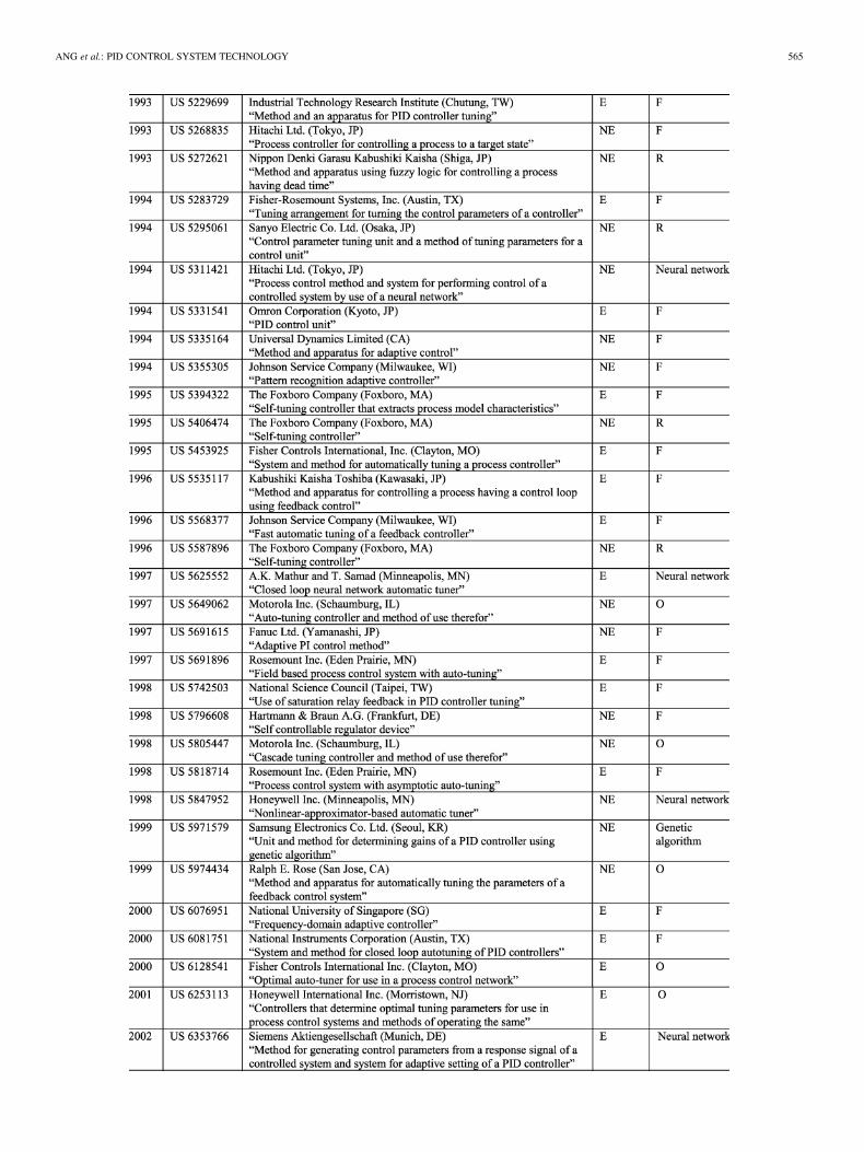
TABLE IIIPATENTS ON PID TUNING
ANG et al.: PID CONTROL SYSTEM TECHNOLOGY 565

566 IEEE TRANSACTIONS ON CONTROL SYSTEMS TECHNOLOGY, VOL. 13, NO. 4, JULY 2005
ANG et al.: PID CONTROL SYSTEM TECHNOLOGY 567
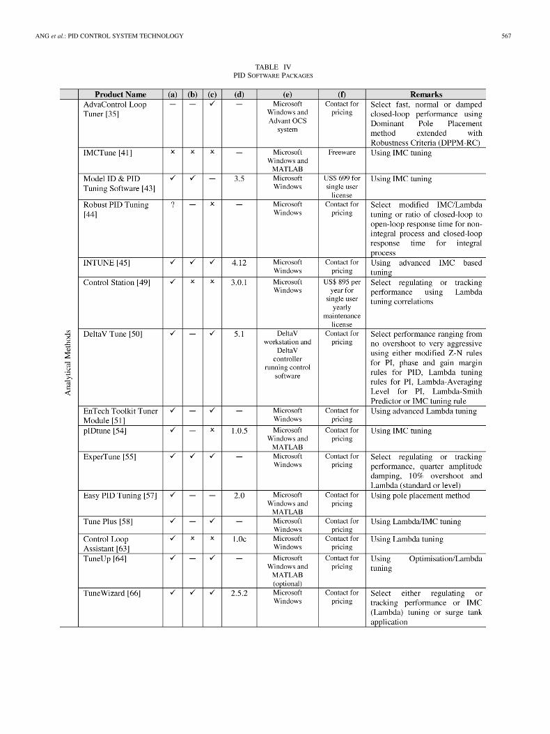
TABLE IVPID SOFTWARE PACKAGES

568 IEEE TRANSACTIONS ON CONTROL SYSTEMS TECHNOLOGY, VOL. 13, NO. 4, JULY 2005

ANG et al.: PID CONTROL SYSTEM TECHNOLOGY 569

570 IEEE TRANSACTIONS ON CONTROL SYSTEMS TECHNOLOGY, VOL. 13, NO. 4, JULY 2005
TABLE VCOMMERCIAL PID CONTROLLER HARDWARE MODULES
Again, PIDeasy provides optimal parameters within a mil-lisecond. The results on the GM and PM are shown in Table II,confirming the software-based PIDeasy approach is stable androbust against model variations. Therefore, this software-basedapproach has a wide applicability and should provide a usefulengine for onboard or onchip controller design. It also providesan excellent starting point for higher order and nonlinear plantsto swiftly tune a network of PID controllers ad hoc [10].
III. PID PATENTS
A. Patents Filed
This section focused on the currently patented tuningmethods that are often adopted in industry for PID design toolsand hardware modules. A range of patents on PID tuning arebeing studied and analyzed, which are chronologically listed inTable III. There are 64 such patents filed in the United States

ANG et al.: PID CONTROL SYSTEM TECHNOLOGY 571
(US), 11 in Japan (JP), 2 in Korea (KR) and 2 by the WorldIntellectual Property Organization (WO). Note that a Koreanpatent (KR 9 407 530) is not included in the following analysisas it is not available in English. Readers may refer to [12] and[30] for detailed information on each patent.
B. Identification Methods for Tuning
Most of the tuning methods patented rely on an identificationof plant dynamics, using an excitation (E) or nonexcitation (NE)type of method. The excitation type can be broken down furtherinto time- or frequency-domain method.
Excitation is often used during plant set-up and commis-sioning in order to set initial PID parameters. Time-domainexcitations are usually a step or pseudorandom binary sequence(PRBS) applied in an open-loop fashion. This is a classicaland the most widely practised method. It is often adopted formodel-based tuning methods. Frequency-domain excitationsusually use a relay-like method, where the plant will undergoa controlled self-oscillation. This type of identification doesnot normally require a parametric model in tuning a PID con-troller, which is the main advantage over time-domain basedidentification.
Generally, nonexcitation type of identification is preferred byindustry due to safety reasons, particularly during normal oper-ations, as this does not upset the plant. An increasing number ofpatents are now filed on nonexcitation identification, as seen inFig. 6.
C. Tuning Methods Patented
Most of the identification and tuning methods patented areprocess engineering oriented and appear rather ad hoc. Shownin Table III, patented tuning methods are mostly formula-based(F), rule-based (R), and optimization-based (O). Formula-basedmethods first identified the characteristics of the plant and thenperform a mapping (similar to the Z-N formula). These areoften used in on-demand tuning for responsiveness. Rule-basedmethods are often used in adaptive control, but can be quitecomplex and ad hoc. These can be expert systems, includingsimple heuristics and fuzzy logic rules. Optimization-basedmethods are often applied offline or on very slow processes,using a conventional (such as least mean squares) or an uncon-ventional (such as genetic algorithms [13]) search method.
Fig. 7 shows that formula-based tuning methods are still themost actively developed, while other methods receive an in-creasing attention. However, most do not yield global or multi-objective optimal performance and their applicability is, hence,often limited.
IV. PID SOFTWARE PACKAGES
A. Software Packages
Due to the lack of a simple and widely applicable tuningmethod, a need for the development of easy to use PID tuningsoftware has therefore arisen. This allows a practitioner withsome control knowledge or plant information to be able to tune aPID controller efficiently and optimally for various applications.It is hoped that such software tools will increase the practising
Fig. 6. Type of identifications used in patents from 1971 to 2000.
Fig. 7. Type of tuning methods used in patents from 1971 to 2000.
Fig. 8. ABB–CEM measurements [2].
company’s system performance and, hence, production qualityand efficiency without needing to invest a vast amount of timeand manpower in testing and adjusting control loops.
Table IV analyzes and summarizes currently availablecommercial PID software packages, grouped by the methodsof their tuning engines whenever known. Note that Adva-Control Loop Tuner (Advant OCS system), DeltaV Tune(DeltaV workstation), Intelligent Tuner (Fisher-RosemountPROVOX controller), OvationTune (Westinghouse DCS),Profit PID (Honeywell TPS/TDC system), PID Self-Tuner(Siemens SIMATIC S7/C7) and Tune-a-Fish (Fisher-Rose-mount PROVOX controller) are for ad hoc systems. Notealso that Tune-a-Fish has been discontinued since 2 April2002 and ExperTune Inc. now handles support and upgrade.IMCTune and CtrlLAB are suitable for learning and testing ofgeneric controller designs, they are also listed in Table IV forinformation.
572 IEEE TRANSACTIONS ON CONTROL SYSTEMS TECHNOLOGY, VOL. 13, NO. 4, JULY 2005
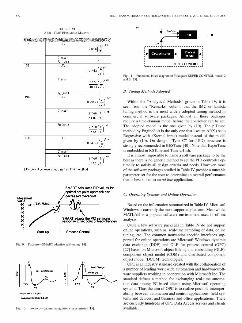
TABLE VIABB—ITAE EFORMULA MAPPING
Fig. 9. Foxboro—SMART adaptive self-tuning [14].
Fig. 10. Foxboro—pattern recognition characteristics [15].
Fig. 11. Functional block diagram of Yokogawa SUPER CONTROL modes 2and 3 [33].
B. Tuning Methods Adopted
Within the “Analytical Methods” group in Table IV, it isseen from the “Remarks” column that the IMC or lambdatuning method is the most widely adopted tuning method incommercial software packages. Almost all these packagesrequire a time-domain model before the controller can be set.The adopted model is the one given by (10). The pIDtunemethod by EngineSoft is the only one that uses an ARX (AutoRegressive with eXternal input) model instead of the modelgiven by (10). On design, “Type C” (or I-PD) structure isstrongly recommended in BESTune [40]. Note that ExperTuneis embedded in RSTune and Tune-a-Fish.
It is almost impossible to name a software package to be thebest as there is no generic method to set the PID controller op-timally to satisfy all design criteria and needs. However, mostof the software packages studied in Table IV provide a tuneableparameter set for the user to determine an overall performancethat is best suited to an ad hoc application.
C. Operating Systems and Online Operation
Based on the information summarized in Table IV, MicrosoftWindows is currently the most supported platform. Meanwhile,MATLAB is a popular software environment used in offlineanalysis.
Quite a few software packages in Table IV do not supportonline operations, such as, real-time sampling of data, onlinetuning, etc. The common nonvendor specific interfaces sup-ported for online operations are Microsoft Windows dynamicdata exchange (DDE) and OLE for process control (OPC)[27] based on Microsoft object linking and embedding (OLE),component object model (COM) and distributed componentobject model (DCOM) technologies.
OPC is an industry standard created with the collaboration ofa number of leading worldwide automation and hardware/soft-ware suppliers working in cooperation with Microsoft Inc. Thestandard defines a method for exchanging real-time automa-tion data among PC-based clients using Microsoft operatingsystems. Thus the aim of OPC is to realize possible interoper-ability between automation and control applications, field sys-tems and devices, and business and office applications. Thereare currently hundreds of OPC Data Access servers and clientsavailable.
ANG et al.: PID CONTROL SYSTEM TECHNOLOGY 573
D. Modern Features
Remedial features such as differentiator filtering and inte-grator anti-windup are now mostly accommodated in a PIDsoftware package. Now the trend is to provide some addi-tional features, such as diagnostic analysis, which prove tobe very helpful in practice. An example is highlighted byExperTune, which includes a wide range of fault diagnosisfeatures, such as valve wear analysis, robustness analysis, au-tomatic loop report generation, multivariable loop analysis,power spectral density plot, auto and cross correlations plot,and shrink-swell (inverse response) process optimization, etc.Other additional features seen in commercial PID packagesinclude user-friendly interfaces, support of a variety of con-troller structures and allowing more user-defined settings indetermining PID parameters when necessary.
V. PID HARDWARE MODULES
A. Hardware and Auto-Tuning
Many PID software features are now incorporated in hard-ware modules, particularly those used in process control. Arange of these are available from the four dominant vendors,namely, ABB, Foxboro, Honeywell and Yokogawa, as listedin Table V. Hardware brands from Elsag Bailey, Kent-TaylorInstruments, Hartmann & Braun and Alfa Laval have beenacquired by ABB. The following brands have been acquiredunder Emerson Process Management Group, namely, BrooksInstrument, Daniel, DeltaV, Fisher, Intellution, Micro Motion,PROVOX, Rosemount, RS3 and Westinghouse Process Con-trol. Invensys Production Management Division consists ofAPV, Avantis, Esscor, Eurotherm, Foxboro, Pacific Simulation,Triconex, and Wonderware. Readers may refer to [3], [4], [9],[19], [20], [25], and [31] for more information on commercialPID controllers.
Based on a survey carried out by Control Engineering in 1998[11], single-loop models account for 64% of the controllers,while multiloop, 36%. It also reveals that 85% of the loop con-trollers are used for feedback control, 6% for feedforward con-trol, and 9% for cascade control. The most important featuresthat are expected from a loop controller are, in order of im-portance, PID function, start-up self-tuning, online self-tuning,adaptive control and fuzzy logic.
Many PID controller manufacturers provide various facilitiesin their products that allow easy tuning of the controller. As seenin PID patents and software packages, most of the hardwaresystems also adopt a time-domain tuning method, while a mi-nority rely on open-loop relay experiments. Some modules offergain-scheduling capabilities and, hence, can cover a large op-eration envelope. Some are more adaptive, using online modelidentification or rules inferred from online responses.
Automated tuning is mainly implemented through ei-ther “tuning on demand” with upset or “adaptive tuning.”Some manufacturers refer ‘tuning on demand’ with upset as“self-tune,” “auto-tune” or “pretune,” while “adaptive tuning”is sometimes known as “self-tune,” “auto-tune” or “adaptivetune.” There exists no standardization in the terminology.
“Tuning on demand” with upset typically determines the PIDparameters by inducing a controlled upset in the process. This
allows measurements of the process response so as to calculatethe appropriate controller parameters. “Adaptive tuning” aimsto set the PID parameters without inducing upsets. When a con-troller is utilising this function, it constantly monitors the PVfor any oscillation around the set-point and, hence, closed-loopidentification can be as effective as in “tuning on demand.” Thistype of tuning is ideal for processes where load characteristicschange drastically while the process is running. If there is anyoscillation, the controller adjusts the PID parameters in an at-tempt to eliminate them. It cannot be used effectively, however,if the process has externally induced upsets for which the con-trol could not possibly be tuned out.
B. ABB Controllers
ABB controllers offer two auto-tuning options, namely,quarter-wave and minimal overshoot. They also come with amanual fine-tuning option called control efficiency monitor(CEM). As shown in Fig. 8, six “key-performance” parameterslabeled are measured and displayed, allowing the user to varythe PID settings to match the process needs and to fine-tunemanually.
ABB also offers another tuning algorithm for its Micro-DCIseries, the Easy-Tune. The Easy-Tune algorithm approximatesa process by a first-order plus delay model, as shown in (10). Ituses a typical graphical method, where the step changes are ap-plied so as to measure the gain, delay and rise-time and, hence,the time-constant. These are then used to map the controller pa-rameters through formulae shown in Table VI [1], which are op-timized for the integral of time-weighted absolute error (ITAE)performance index.
It is unclear, unfortunately, whether the three plant parame-ters are continuously identified so as to vary the PID parametersonline. If they are, however, Micro-DCI series should be verypowerful in dealing with changing plant dynamics through con-tinuously scheduled optimal PID settings.
C. Foxboro Series
Foxboro 716C, 718, and 731C series use a proprietary self-tuning algorithm SMART. During start-up and control, SMARTcontinuously monitors the PV and automatically adjusts the PIDparameters according to the response of the PV, as shown inFig. 9. The advantage of SMART is its ability to operate withoutinjecting any artificial change into the system.
Foxboro 743C, 760C, 761C, 762C, and T630C controllersuse another patented self-tuning algorithm, expert adaptivecontroller tuning (EXACT). EXACT does not use a parametricmodel, but adjusts the controller based on pattern recognitionresults of the actual current process. When it senses a processupset, it immediately takes corrective action for the patternrecognition. The user can choose the threshold levels of desireddamping and overshoot-to-load changes, as shown in Fig. 10.EXACT needs to have a good initial PID parameter set tostart with in order to achieve satisfactory performance. Thus,the initial PID parameters are determine by introducing asmall perturbation to the process and use the resulting processreaction curve to calculate. To start up the control system, engi-neers must determine an anticipated noise-band and maximum

574 IEEE TRANSACTIONS ON CONTROL SYSTEMS TECHNOLOGY, VOL. 13, NO. 4, JULY 2005
wait-time of the process. The noise-band is a value repre-senting expected amplitude of noise on the feedback signal.The maximum wait-time is the maximum time that EXACTalgorithm will wait for a second peak in the feedback signalafter detecting a first peak. These two settings are crucial inorder for the EXACT algorithm to have optimal performancebut can be quite tricky to determine.
All Foxboro’s controllers studied here are rule-based, insteadof model-based but do not support feedforward control. If theysupport gain scheduling, however, they will be very effective forthe entire operating envelope, as gain-scheduling can be moreuseful than continuous adaptation in most situations [3].
D. Honeywell Tuners
Honeywell offers a “tuning on demand” controller, Autotune,which is not adaptive or continuous. They also offer an adaptivetuner, Accutune, which uses a combination of frequency andtime response analysis plus rule-based expert system techniquesto identify the process continually. An enhanced version of thisis, Accutune II, which incorporates a fuzzy logic overshootsuppression mechanism. It provides a “plug-and-play” tuningalgorithm, which will starts at the touch of a button or throughan input response data set identify and tune for any processesincluding integrating processes and those with a dead-time.This speeds up and simplifies the startup process and allowsretuning at any set-point in an “automatic mode.” The fuzzylogic overshoot suppression function operates independentlyfrom Accutune tuning as an add-on. It does not change thePID parameters, but temporarily modifies the control action tosuppress overshoot. Although this makes the control systemmore complex and difficult to analyze, it allows more aggressiveaction to co-exist with smooth process output. It can be disabled,depending on the application or user requirements, and shouldbe unnecessary if the PID controller is set adaptively optimally.
E. Yokogawa Modules
Yokogawa first introduced its SUPER CONTROL moduleover a decade ago. Similar to Honeywell’s Accutune II, it alsouses a fuzzy logic based algorithm to eliminate overshoots,mimicking control expertise of an experienced operator. Itconsists of two main parts, namely, the set-point modifier andthe set-point selector.
The set-point modifier models the process and functions asan “expert operator” by first considering that a PID controlleris difficult to tune to deliver both a short rise-time and a lowovershoot. It thus seeks a knowledge base about the process, itsdynamics, and any nonlinearity of the process (including loadchanges). Then it leads the system into performing perfectly byfeeding artificial target set-points into the PID block through theset-point selector.
In particular, SUPER CONTROL operates on three modes.Mode 1 is designed for overshoot suppression by observing therate of change when the process output approaches a new targetset-point. It installs “subset points” as the process output ap-proaches set-point to insure overshoot does not occur. Mode 2is for ensuring high stability at the set-point while sacrificingsome response time to a set-point change. Mode 3 is for a fasterresponse than Mode 2 to a set-point or load change with some
compromise in stability when a new set-point is entered and asthe process output approaches that change. The process blockis simply the first-order lag time with gain model and it simu-lates the PV without any inherent dead time. A functional blockdiagram for Modes 2 and 3 is shown in Fig. 11. If Mode 2 or3 observes any phase shift that has changed from normal oper-ating conditions, it uses the process model to compute a calcu-lated process variable (CPV) and attempts to suppress PV fromhunting. The compensation model switches between the mea-sured PV and CPV while the control function block performsthe normal PID computation. It is unclear how the three modesare switched between, but it would be advantageous if this isscheduled automatically.
F. Remarks
Many PID hardware vendors have made tremendous effortsto provide a built-in tuning facility. Owing to their vast expe-rience on PID control, most manufacturers have incorporatedtheir knowledge base into their algorithms. Current PID con-trol modules provide “tuning on demand” with upset or “adap-tive tuning” or both, depending on the model and user settings.Either technique has its advantages and disadvantages. For ex-ample, if using “tuning on demand” only, the controller needsto be retuned periodically and whenever changes occur in theprocess dynamics. This can be quite tedious and sometimesunder-performance can be too late to notice. Therefore, “tuningon demand” coupled with “gain-scheduling” could provide anadvantage.
If relying on an “adaptive tuner” only, the range of changesthat can be covered is rather limited and a classical step-responsemodel is still needed for determining initial PID settings. Be-fore normal operations may begin, these systems generally re-quire a carefully supervised start-up and testing period. Further,the more controller parameters the operator needs to select, themore difficult it is to adjust for optimal performance and thelonger it takes to prepare for the operation. Nevertheless, oncethe controller is correctly configured, it can constantly monitorthe process and automatically adjust the controller parametersto adapt to changes in the process.
The second effort made by many PID hardware vendors ap-pears to be incorporating an overshoot suppression function intheir onboard algorithms. In order to meet multiple objectiveshighlighted in Section II-G, they have also added other func-tions to a standard PID algorithm or allowed the user to switchbetween modes. However, these features are not commonly seenin commercial software packages (see Table IV).
VI. CONCLUSION
PID, a structurally simple and generally applicable controltechnique, stems it success largely from the fact that it just worksvery well with a simple and easy to understand structure. Whilea vast amount of research results are published in the literature,there exists a lack of information exchange and analysis. Thiscan lead to some misunderstanding between academia and in-dustry. For example, there exists no standardization of a genericPID structure for control engineering practice. This is partic-ularly evident with analogue PID controllers being replaced by

ANG et al.: PID CONTROL SYSTEM TECHNOLOGY 575
digital ones, where flexibility in software permits ad hoc patchesfor some local optimality. It has led to unnecessary complicationand extra learning curve in tuning PID controllers. This problembecomes severe when there are multiple control loops and dif-ferent brands or models of PID controllers involved in one appli-cation. These may explain why the argument exists that academ-ically proposed tuning rules do not work well on industrial PIDcontrollers, while it is desired that years of research results helpindustrial practice more for improved quality and profitability.
Many PID patents filed so far focus on automatic tuning forprocess control. This starts from conventional or “intelligent”system identification and is more resembled to hardware mod-ules. Software packages are mainly focused on offline simula-tion and have thus a different objective. While automatic tuningis offered in many commercial PID products for multiple op-timality, timeliness continues to pose a challenge. The majordifficulty appears in delivering an optimal transient response,due to difficulties in setting an optimal derivative term. Hence,modifications to the easy-to-understand PID structure have beenmade through the use of artificial intelligence so as to suppressovershoots. In order to meet multiple objectives, switching be-tween different functional modes has also been offered in PIDhardware modules.
The present trend in tackling PID tuning problem is to be ableto use the standard PID structure to meet multiple design objec-tives over a reasonably range of operations and systems. Stan-dardization or modularization around this structure should alsohelp improve cost-effectiveness of PID control and its mainte-nance. This way, robustly optimal tuning method can be devel-oped, as evident in PIDeasy. With the inclusion of system identi-fication techniques, the entire PID design and tuning process canbe automated and modular building blocks can be made avail-able for timely online application and adaptation. This wouldbe particularly suited to “system-onboard” or “system-on-chip”integration for future consumer electronics and MEMS.
REFERENCES
[1] ABB, Instruction Manual of MICRO-DC 53SL6000, 2001.[2] , Specification DataFile of Commander 355, 2001.[3] K. J. Åström, T. Hägglund, C. C. Hang, and W. K. Ho, “Automatic tuning
and adaptation for PID controllers—a survey,” Control Eng. Pract., vol.1, no. 4, pp. 699–714, 1993.
[4] K. J. Åström and T. Hägglund, PID Controllers: Theory, Design, andTuning. Research Triangle Park, NC: Instrument Soc. Amer., 1995.
[5] , “PID Control,” in The Control Handbook, W. S. Levine,Ed. Piscataway, NJ: IEEE Press, 1996, pp. 198–209.
[6] , Benchmark Systems for PID Control, pp. 165–166, 2000.[7] , “The future of PID control,” Control Eng. Pract., vol. 9, no. 11,
pp. 1163–1175, 2001.[8] C. Bohn and D. P. Atherton, “An analysis package comparing PID anti-
windup strategies,” IEEE Control Syst. Mag., vol. 15, no. 2, pp. 34–40,Apr. 1995.
[9] R. Cao and T. McAvoy, “Evaluation of a pattern recognition adaptivePID controller,” Automatica, vol. 26, no. 4, pp. 797–801, Jul. 1990.
[10] G. Chong and Y. Li, “Trajectory controller network and its designautomation through evolutionary computing,” in Proc. EvoWorkshops2000: Real-World Applications of Evolutionary Computing, Edinburgh,U.K., Apr., pp. 139–146.
[11] (1998, May) Control Engineering—Single-Loop Controllers Domi-nate Marketplace. [Online] http://www.manufacturing.net/ctl/article/CA189 397
[12] (2004, Jun.) B1—esp@cenet—Your Gateway to Patents. [Online]http://gb.espacenet.com
[13] W. Feng and Y. Li, “Performance indexes in evolutionary CACSD au-tomation with application to batch PID generation,” in Proc. 10th IEEEInt. Symp. Computer Aided Control System, Hawaii, Aug. 1999, pp.486–491.
[14] Foxboro, Product Specifications of I/A Series 716C 1/16 DIN Temper-ature Controller, 1996.
[15] , Technical Information of EXACT Tuning With 762, 760, and 740Series Controllers, Aug. 1995.
[16] J. P. Gerry, “A comparison of PID control algorithms,” Control Eng.,vol. 34, no. 3, pp. 102–105, Mar. 1987.
[17] J. P. Gerry and F. G. Shinskey. (2004, May) PID Controller Specification(White Paper). [Online] http://www.expertune.com/PIDspec.htm
[18] R. Gorez, “A survey of PID auto-tuning methods,” J. A, vol. 38, no. 1,pp. 3–10, 1997.
[19] T. Hägglund and K. J. Åström, “Industrial adaptive controllers based onfrequency response techniques,” Automatica, vol. 27, no. 4, pp. 599–609,Jul. 1991.
[20] C. C. Hang and K. K. Sin, “A comparative performance study of PIDauto-tuners,” IEEE Control Syst. Mag., vol. 11, no. 5, pp. 41–47, Aug.1991.
[21] “Getting the best out of PID in machine control,” in Proc. Dig. Inst.Elect. Eng. PG16 Colloquium (96/287), London, U.K., Oct. 24, 1996.
[22] A. Kaya and T. J. Scheib, “Tuning of PID controls of different struc-tures,” Control Eng., vol. 35, no. 7, pp. 62–65, Jul. 1988.
[23] Y. Li, W. Feng, K. C. Tan, X. K. Zhu, X. Guan, and K. H. Ang, “PIDeasyand automated generation of optimal PID controllers,” in Proc. 3rd Asia-Pacific Conf. Control and Measurement, Dunhuang, P.R. China, 1998,pp. 29–33.
[24] P. Marsh, “Turn on, tune in,” New Electron., vol. 31, no. 4, pp. 31–32,1998.
[25] B. J. Minter and D. G. Fisher, “A comparison of adaptive controllers:academic vs industrial,” in Proc. Amer. Control Conf., Atlanta, GA,1988, pp. 1653–1658.
[26] A. O’Dwyer, Handbook of PI and PID Controller TuningRules. London, U.K.: Imperial College Press, 2003.
[27] OPC Foundation. (2002, June) The OPC Foundation—Dedicated to In-teroperability in Automation. [Online] http://www.opcfoundation.org
[28] “Digital control: past, present and future of PID control,” in Proc. IFACWorkshop, J. Quevedo and T. Escobet, Eds., Terrassa, Spain, Apr. 5–7,2000.
[29] F. G. Shinskey, Feedback Controllers for the Process Industries. NewYork: McGraw-Hill, 1994.
[30] (2004, Jun.) Patents—Patent Full-Text and Full-Page Image Databases.[Online] http://ww.uspto.gov/patft
[31] H. J. Versteeg, H. J. Jansma, and K. Turner, “Evaluation of commerciallyavailable adaptive controllers,” J. A, vol. 27, no. 3, pp. 120–126, 1986.
[32] L. Wang, T. J. D. Barnes, and W. R. Cluett, “New frequency-domaindesign method for PID controllers,” Proc. Inst. Elect. Eng. D—ControlTheory Appl., vol. 142, no. 4, pp. 265–271, 1995.
[33] C. Wilson and C. Callen. (2004, Jan.) Close Process Control Trans-lates To Quality Heat Treated Parts. [Online] http://www.industrial-heating.com/CDA/ArticleInformation/coverstory/BNPCoverStoryItem/0,2830,116383,00.html
[34] J. G. Ziegler and N. B. Nichols, “Optimum settings for automatic con-trollers,” Trans. ASME, vol. 64, pp. 759–768, 1942.
[35] ABB. (2004, May) The ABB Group. [Online] http://www.abb.com[36] ACT. (2004, May) ACT GmbH Homepage. [Online] http://www.act-
control.com[37] ADAPTECH. (2004, May) Adaptech—Identification and Advanced
Control. [Online] http://www.adaptech.com/Ang/menu_a.html[38] Algosys Inc. (2004, May) Algosys—Solutions & Technology. [Online]
http://www.algosys.com/solutions/stdtech.asp[39] Artcon Inc. (2004, May) Artcon Inc. [Online] http://artcon.com/
artcon.html[40] BESTune. (2004, May) PID Controller Tuning. [Online]
http://bestune.50megs.com[41] C. B. Brosilow. (2002, Jun.) Coleman Brosilow. [Online]
http://www.cwru.edu/cse/eche/people/faculty/brosilow/brosilow.htm[42] Communications & Systems. (2004, May) COTEMS. [Online]
http://www.cotems.com/anglais/default.htm[43] Control Arts Inc. (2004, May) Control Arts Inc: Process Control, Alarm
Analysis, Abnormal Situation Management, Engineering Analysisand Operations Management Software. [Online] http://www.contro-lartsinc.com/index.html
[44] Control & Optimization Specialists. (2004, May) COSpecialists—Con-trol & Optimization Specialists. [Online] http://www.cospecialists.com/index.html

576 IEEE TRANSACTIONS ON CONTROL SYSTEMS TECHNOLOGY, VOL. 13, NO. 4, JULY 2005
[45] Control Soft Inc. (2004, May) Control Soft Inc.—The CompanyWith Leading Control Technologies. [Online] http://www.control-softinc.com/index.shtml
[46] CP Engineering Systems Ltd. (2004, May) NF CADET V12 Page 1.[Online] http://www.cpengineering.com/exthtmnf/Nfcadetv12.html
[47] Cutler Johnston Corporation. (2004, May) Products. [Online]http://www.cutlerjohnston.com/Products.htm
[48] Delta Tau Data Systems Inc. (2004, May) PMAC Executive Pro Suite.[Online] http://www.deltatau.com/PMACExecutiveSuite.htm
[49] D. Cooper. (2004, May) Control Station is Software forProcess Control Training, Tuning and Analysis. [Online]http://www.engr.uconn.edu/control/index.html
[50] DeltaV Tune. (2004, May) DeltaV/Product Data Sheet. [Online]http://www.easydeltav.com/productdata/pds/index.asp
[51] EnTech Toolkit Tuner Module. (2004, May) Emerson Process Man-agement—EnTech—Tuner Module. [Online] http://www.emersonpro-cess.com/entechcontrol/products/tune/index.asp
[52] Intelligent Tuner. (2004, May) PROVOX/Product Data/Control. [On-line] http://www.provox-secure.com/product/control.asp
[53] OvationTune. (2004, May) Westinghouse Process Control: Products:Ovation: Descriptions: Tuning Tools. [Online] http://www.westing-housepc.com/ovation/details-tuningtools.cfm
[54] EngineSoft. (2002, Jun.) pIDtune—Integrated System Identification andPID Controller Design. [Online] http://www.pidtune.com/index.html
[55] ExperTune Inc. (2004, May) Process Performance Monitoring &Optimization, Analysis, Simulation, and PID Tuning. [Online]http://www.expertune.com
[56] Honeywell International Inc. (2004, May) http://www.acs.Honey-well.com/ichome/rooms/DisplayPages/LayoutInitial. [Online] http://www.acs.honeywell.com
[57] Ingénierie Pour Slgnaux et Systèmes (IPSIS). (2004, May) EasyPID Tuning. [Online] http://www.ipsis.com/produits/Pidtuning/pid-tuning.htm
[58] Tune Plus—PID Tuning Product, Innovention Industries Inc. (2004,May). http://www.innovin.com/tuneplus.htm [Online]
[59] IPCOS Netherlands/Belgium. (2004, May) IPCOS Creators in Control.[Online] http://www.ipcos.be/welcome.htm
[60] ISE Inc. (2004, May) Commander Software Data Sheet. [Online]http://instserv.com/commande.htm
[61] Israel Electric Corporation. (2004, May) Optimal PID TuningThrough Best Process Identification. [Online] http://www.geoci-ties.com/ugf4aggnn/CSTPmain.htm
[62] JC Systems. (2004, May) Untitled Document. [Online] http://www.jc-systemsinc.com/html/tool_oview.html
[63] Lambda Controls. (2004, May) Lambda Controls: A Process ControlOptimization Company. [Online] http://www.lambdacontrols.com
[64] Metso Automation Inc. (2004, May) Metso Automation—High LevelAutomation Solutions, Systems and Services. [Online] http://www.met-soautomation.com/automation/home.nsf/FR?ReadForm&ATL=/Au-tomation/Epprod.nsf/WebWID/WTB-010 912-2256A-8C73F
[65] National Instruments. (2004, May) LabVIEW PID Control Toolset forWindows—Products and Services—National Instruments. [Online]http://sine.ni.com/apps/we/nioc.vp?cid=1394&lang=US
[66] Plant Automation Services Inc. (2004, May) PAS Home Page. [Online]http://www.tunewizard.com
[67] S. Raczynski. (2004, May) PID Controller Settings. [Online]http://www.raczynski.com/pn/pids.htm
[68] Rockwell Automation. (2004, May) RSTune—Overview. [Online]http://www.software.rockwell.com/rstune/
[69] Siemens. (2004, May) Siemens—SIMATIC Technology—PID Control.[Online] http://www.ad.siemens.de/simatic/regelsysteme/html_76/pro-dukte/sbpidcontr2.htm
[70] SpecializedControl. (2002, Jun.) PID Control Tuning—Analyt-ical PID Tuning Methods for Feedback Control Systems. [Online]http://www.specializedcontrol.com
[71] Straight-Line Control Co. Inc. (2004, May) Controller Tuning 101. [On-line] http://members.aol.com/pidcontrol/software.html
[72] Techmation Inc. (2004, May) Techmation. [Online] http://protuner.com[73] TiPS Inc. (2002, Oct.) TiPSWEB Tune-a-Fish Page. [Online]
http://www.tipsweb.com/tuneafish.htm[74] Matrikon Inc. (2004, May) Advanced Process Control—ProcessACT
at Matrikon.com. [Online] http://www.matrikon.com/products/proces-sact/index.asp
[75] Visual Solutions Inc. (2004, May) Visual Solutions, Inc.—VisSim,VisSim/Comm & VisSim/DSP Home Page. [Online] http://www.vissim.com/products/addons/optimize.html
[76] Xiera Technologies Inc. (2004, May) GeneX. [Online]http://www.xiera.com/genex.htm
[77] D. Xue. (2004, May) MATLAB Central File Exchange—CtrlLAB.[Online] http://www.mathworks.com/matlabcentral/fileexchange/Files.jsp?fileId=18
Kiam Heong Ang received the B.Eng. and Ph.D. de-grees in electronics and electrical engineering fromUniversity of Glasgow, Glasgow, U.K., in 1996 and2005, respectively.
From 1997 to 2000, he was a Software Engineerwith Advanced Process Control Group, YokogawaEngineering Asia Pte. Ltd., Singapore. Since 2005,within the same company, he has been working onprocess industry standardization and researchinginto new technologies for future Yokogawa products.His current research interests include evolutionary
multi-objective learning, computational intelligence, control systems andengineering design optimization.
Gregory Chong (S’99) received the B.Eng. degreein electronics and electrical engineering from Univer-sity of Glasgow, Glasgow, U.K., in 1999. He is cur-rently working toward the Ph.D. degree at the sameuniversity.
His current research interests include evolutionarymultiobjective and intelligent control for nonlinearsystems.
Yun Li (S’87–M’90) received the B.Sc. degree inradio electronics science from Sichuan University,Chengdu, China, in 1984, the M.Sc. degree inelectronic engineering from University of Elec-tronic Science and Technology of China (UESTC),Chengdu, in 1987, and the Ph.D. degree in com-puting and control engineering from University ofStrathclyde, Glasgow, U.K., in 1990.
From 1989 to 1990, he worked at the U.K. Na-tional Engineering Laboratory and for Industrial Sys-tems and Control Limited, Glasgow, U.K. He became
a Lecturer at the University of Glasgow in 1991. In 2002, he served as a VisitingProfessor at Kumamoto University, Japan. He is currently a Senior Lecturer atUniversity of Glasgow and a Visiting Professor at UESTC. In 1996, he inde-pendently invented the “indefinite scattering matrix” theory, which opened upa ground-breaking way for microwave feedback circuit design. From 1987 to1991, he carried out leading work in parallel processing for recursive filteringand feedback control. In 1992, he achieved first symbolic computing for circuitdesign power electronic, without needing to invert any matrix, complex-num-bered or not. Since 1992, he has pioneered into design automation of controlsystems and discovery of novel engineering systems using evolutionary learningand search techniques. He has produced 11 Ph.D. degrees in this area and hasover 130 publications.
Dr. Li is a Chartered Engineer and a Member of the Institution of ElectricalEngineers. He established the IEEE CACSD Evolutionary ComputationWorking Group and the European Network of Excellence in EvolutionaryComputing (EvoNet) Workgroup on Systems, Control, and Drives in 1998.